Up to l 1500 lpm, 400 US gpm l 480 bar, 7000 psi Features l FLOW: 1 - 1500 lpm 0.25 - 400 US gpm l PRESSURE: Up to 480 bar, 7000 psi l ACCURACY: Up to 1% of indicated reading l FREQUENCY OUTPUT l BI-DIRECTIONAL operation l TEMPERATURE: sensor built-in l FLUIDS: Wide range of hydraulic oil, lubrication oil, and fuels l CALIBRATION: 21 cSt as standard. Special calibration possible LT-BU-ENG-1401.pdf 07/11 (Issue 4) The LT turbine flow meter with frequency output provides a precision solution to the flow measurement of hydraulic systems on test stands, machine tools and other fixed or mobile applications. The flow meter can be installed anywhere in the hydraulic circuit for production testing, commissioning, development testing and analysis of control systems. The compact design allows the LT series flow meters to be installed where space is limited. The LT turbine flowmeter has a frequency output and is the ideal tool for monitoring the performance of pumps, motors, valves and hydrostatic transmissions.
Transcript
Up tol 1500 lpm, 400 US gpm l 480 bar, 7000 psi
Featuresl FLOW: 1 - 1500 lpm
0.25 - 400 US gpm
l PRESSURE: Up to 480 bar, 7000 psi
l ACCURACY: Up to 1% of indicated reading
l FREQUENCY OUTPUT
l BI-DIRECTIONAL operation
l TEMPERATURE: sensor built-in
l FLUIDS: Wide range of hydraulic oil, lubrication oil, and fuels
l CALIBRATION: 21 cSt as standard. Special calibration possible
LT-BU-ENG-1401.pdf 07/11(Issue 4)
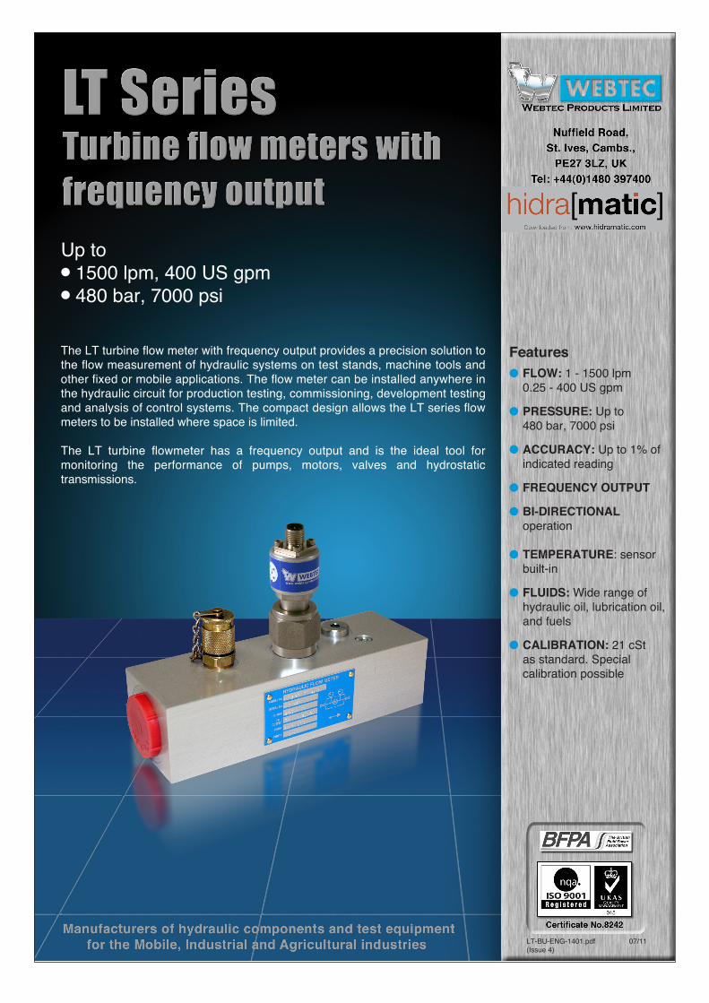
The LT turbine flow meter with frequency output provides a precision solution to the flow measurement of hydraulic systems on test stands, machine tools and other fixed or mobile applications. The flow meter can be installed anywhere in the hydraulic circuit for production testing, commissioning, development testing and analysis of control systems. The compact design allows the LT series flow meters to be installed where space is limited.
The LT turbine flowmeter has a frequency output and is the ideal tool for monitoring the performance of pumps, motors, valves and hydrostatic transmissions.
FunctionalspecificationAmbienttemperature: 5 to 40 °C (41 - 104 °F)Fluidtype: Oils, fuels, water glycol, water oil emulsionsFluidtemperature: 5 to 90 °C (41 - 194 °F) continuous use.Accuracy: 15 to 100% of range - 1% of indicated reading Below 15% fixed accuracy of 1% of 15% of full scale To obtain 1% of indicated readings a Webtec DHCR must be used. Accuracy with other readouts
1% of full scale. LT15 is 1% of full scale over full range.Output: Frequency - 20 -2000 Hz Impedance - 3700 Ohm, Inductance - 1kHz: 1.55H
ConstructionmaterialFlowbody: 600 / 800 / 1500 High tensile Aluminium 2014A T6 15 / 60 / 150 / 300 / 400 High tensile Aluminium 2011 T6 Internalparts: Aluminium, Steel, Stainless Steel. Transducerbody: Aluminium, Steel - electroless nickel plated, Stainless Steel. Seals: Viton seals as standard EPDM are available - please consult sales office.
OperationAs fluid is passed through the flow block it rotates a precision turbine. The flow straighteners and turbine design minimise the effects of turbulence and swirl. The turbine blades are detected by the magnetic reluctance transducer which produces a pulse output. The flow block has ports for pressure or temperature sensors which can be supplied as an option.ReverseFlowThe flow block is capable of measuring flow in either direction.CalibrationAll units are calibrated with 21 cSt oil as standard. Calibration certificates are available on request - this is a chargeable option. Production calibration of LT1500 lpm turbine is confirmed by testing over the range of 50 to 750 lpm and by design only above 750lpm. Other calibration on request - please consult the sales office. InstallationThe flow block has built-in flow straighteners so the normal recommended length of 10 Ø of straight tube can be reduced to 8 Ø where space is limited. Inlet and outlet connections should always be of a similar bore size to that of the flowmeter to prevent venturi or constriction effects.
The range of flow meters can be used for intermittent or continuous testing of flow in either direction. The flow block can be mounted in any orientation. For heavy duty applications where the flow meter will be used constantly with continuous pressure spikes please contact sales to discuss your application. FiltrationIt is recommended that a 25-micron (10 micron for LT15) filter is installed in the circuit prior to the flow block. TopportsMost flow meters have two additional ports (see table for configuration) in the top face of the flow meter to enable the user to connect both a temperature and pressure senor. The LT15 has one top port. All flow meters come with one M16 x 2 test point fitted as standard.OrderingTo order an LT flow meter please quote the model number from the table above. eg: LT15-FM-B-B-6. All LT flow meters (excluding LT15) can have both a temperature sensor and pressure transducer connected simultaneously.
* LT1500 includes 4 feet on base, add 20 mm (3/4”) to D for full height. LT1500 is fitted with carry handles - not shown on diagram.
Dimensions in mm (inches)
WebtecProductsLimited reserve the right to make improvements and changes to the specification without notice
AccuracyThe accuracy is better described as the uncertainty of the flow reading compared to a known reference. Every flow measurement has an error associated with it, caused by the combination of a large number of factors that affect the operation of the flow meter, these include bearing friction, temperature, viscosity, magnetic drag and the signal strength to name but a few.
All our flow meters are calibrated at 10 points over the flow range and its performance measured against a flow reference that is traceable to International standards. Accuracy is typically quoted in one of two ways: as a percentage of full scale (the maximum calibrated flow) or as a percentage of the indicated reading (the actual flow).
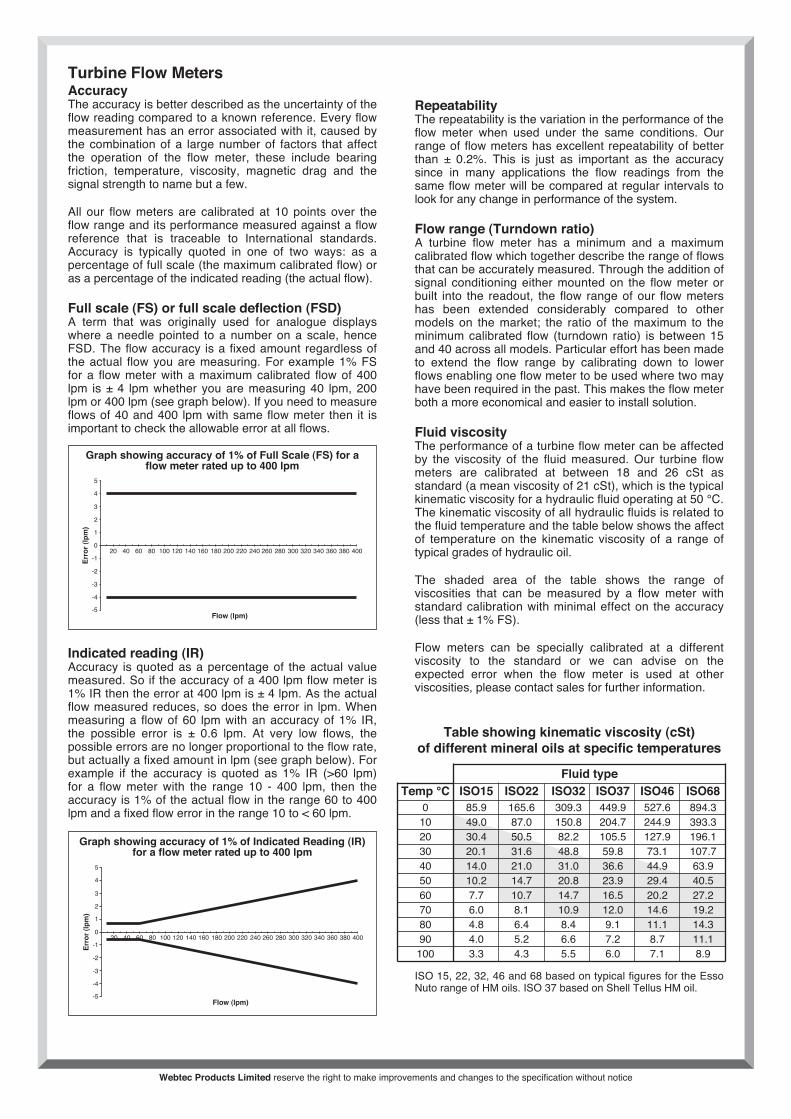
Fullscale(FS)orfullscaledeflection(FSD)A term that was originally used for analogue displays where a needle pointed to a number on a scale, hence FSD. The flow accuracy is a fixed amount regardless of the actual flow you are measuring. For example 1% FS for a flow meter with a maximum calibrated flow of 400 lpm is ± 4 lpm whether you are measuring 40 lpm, 200 lpm or 400 lpm (see graph below). If you need to measure flows of 40 and 400 lpm with same flow meter then it is important to check the allowable error at all flows.
Indicatedreading(IR)Accuracy is quoted as a percentage of the actual value measured. So if the accuracy of a 400 lpm flow meter is 1% IR then the error at 400 lpm is ± 4 lpm. As the actual flow measured reduces, so does the error in lpm. When measuring a flow of 60 lpm with an accuracy of 1% IR, the possible error is ± 0.6 lpm. At very low flows, the possible errors are no longer proportional to the flow rate, but actually a fixed amount in lpm (see graph below). For example if the accuracy is quoted as 1% IR (>60 lpm) for a flow meter with the range 10 - 400 lpm, then the accuracy is 1% of the actual flow in the range 60 to 400 lpm and a fixed flow error in the range 10 to < 60 lpm.
RepeatabilityThe repeatability is the variation in the performance of the flow meter when used under the same conditions. Our range of flow meters has excellent repeatability of better than ± 0.2%. This is just as important as the accuracy since in many applications the flow readings from the same flow meter will be compared at regular intervals to look for any change in performance of the system.
Flowrange(Turndownratio)A turbine flow meter has a minimum and a maximum calibrated flow which together describe the range of flows that can be accurately measured. Through the addition of signal conditioning either mounted on the flow meter or built into the readout, the flow range of our flow meters has been extended considerably compared to other models on the market; the ratio of the maximum to the minimum calibrated flow (turndown ratio) is between 15 and 40 across all models. Particular effort has been made to extend the flow range by calibrating down to lower flows enabling one flow meter to be used where two may have been required in the past. This makes the flow meter both a more economical and easier to install solution.
FluidviscosityThe performance of a turbine flow meter can be affected by the viscosity of the fluid measured. Our turbine flow meters are calibrated at between 18 and 26 cSt as standard (a mean viscosity of 21 cSt), which is the typical kinematic viscosity for a hydraulic fluid operating at 50 °C. The kinematic viscosity of all hydraulic fluids is related to the fluid temperature and the table below shows the affect of temperature on the kinematic viscosity of a range of typical grades of hydraulic oil.
The shaded area of the table shows the range of viscosities that can be measured by a flow meter with standard calibration with minimal effect on the accuracy (less that ± 1% FS).
Flow meters can be specially calibrated at a different viscosity to the standard or we can advise on the expected error when the flow meter is used at other viscosities, please contact sales for further information.