12

2Data subject to change without notice.
HPS Express™ L series, low voltage distribution transformers, offer an ideal combination of features, quality, reliability and performance to provide the most cost effective solution for your commercial applications.
For applications requiring NMX-J-351-ANCE-2016 compliance, please refer to the HPS TrafoLeon brochure.
Typical ApplicationsHPS Express L satisfies the needs of typical electrical power distribution applications including:
Lighting Small Power Distribution HVAC Shopping
Plazas
Office Towers
Residential High-Rise
Commercial Buildings
Big Box Stores
Energy Efficiency
Note: These typical efficiency values are at 35% of nominal load.
Benefits
HPS ExpressTM LCommercial Distribution Transformer
• The flexibility of these low voltage transformers supports connecting in 440, 460 and 480 volts (on the primary side) with the same equipment
• Standard Type 2 enclosure • Standard integral floor and wall mounting brackets up to
45 kVA allow for faster installation• Industry leading design and technology solutions• Unmatched HPS quality and reliability• UL Listed
OUR EXPERIENCEHPS is the largest manufacturer of dry-type transformers in North America with over 100 years of experience. We engineer and manufacture a wide range of standard and custom transformers that are exported globally in electrical equipment and systems. We support industries such as oil and gas, mining, steel, waste and water treatment, and solar power generation.
HPS leads the industry in these markets through our technical design strength, breadth of product and manufacturing capabilities in Mexico, USA, Canada and Asia.
HPS Express L is a general purpose transformer line meeting the following levels:
Three Phase
kVA Efficiency (%)
15 95.7
30 96.1
45 96.6
75 96.5
112.5 97.1
150 97.4
225 97.8
300 97.7
500 98.1
3Data subject to change without notice.
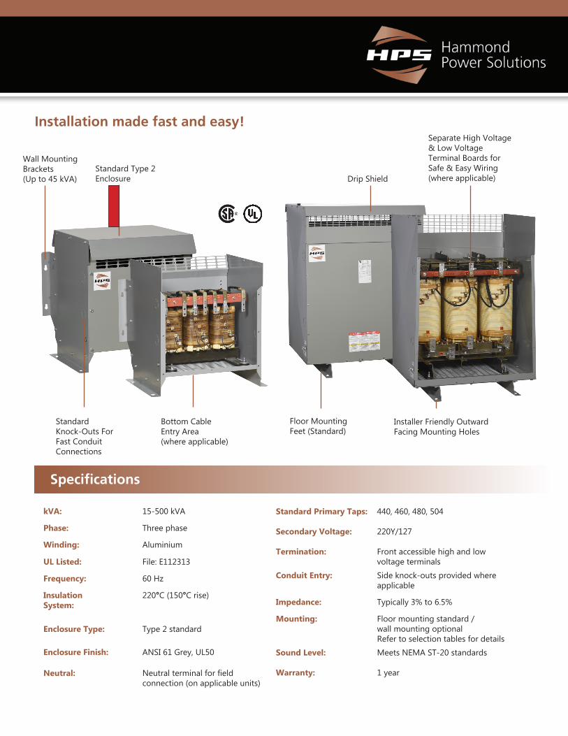
Installation made fast and easy!
Standard Knock-Outs For Fast Conduit Connections
Installer Friendly Outward Facing Mounting Holes
Separate High Voltage & Low Voltage Terminal Boards for Safe & Easy Wiring (where applicable)
Standard Type 2 Enclosure
Bottom Cable Entry Area (where applicable)
Drip Shield
Floor Mounting Feet (Standard)
kVA: 15-500 kVA
Phase: Three phase
Winding: Aluminium
UL Listed: File: E112313
Frequency: 60 Hz
Insulation System:
220°C (150°C rise)
Enclosure Type: Type 2 standard
Enclosure Finish: ANSI 61 Grey, UL50
Neutral: Neutral terminal for field connection (on applicable units)
Standard Primary Taps: 440, 460, 480, 504
Secondary Voltage: 220Y/127
Termination: Front accessible high and low voltage terminals
Conduit Entry: Side knock-outs provided where applicable
Impedance: Typically 3% to 6.5%
Mounting: Floor mounting standard / wall mounting optionalRefer to selection tables for details
Sound Level: Meets NEMA ST-20 standards
Warranty: 1 year
Specifications
Wall Mounting Brackets (Up to 45 kVA)
4Data subject to change without notice.
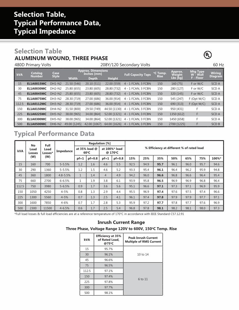
ALUMINUM WOUND, THREE PHASE
kVA Catalog Number
CaseStyle
Approx. DimensionsInches [mm] Full Capacity Taps
oC Temp. Rise
Approx. Weight Lbs [kg]
Mtg TypeW - WallF - Floor
Wiring Diagram
Width Depth Height
15 EL1A0015MC DH1-N2 21.50 [546] 20.10 [511] 22.00 [559] 4 - 1 FCAN, 3 FCBN 150 160 [75] F or W/C SCD A30 EL1A0030MC DH2-N2 25.80 [655] 23.80 [605] 28.80 [732] 4 - 1 FCAN, 3 FCBN 150 280 [127] F or W/C SCD A45 EL1A0045MC DH2-N2 25.80 [655] 23.80 [605] 28.80 [732] 4 - 1 FCAN, 3 FCBN 150 320 [145] F or W/C SCD A75 EL1A0075MC DH3-N2 28.30 [719] 27.00 [686] 36.00 [914] 4 - 1 FCAN, 3 FCBN 150 545 [247] F (Opt W/C) SCD A
112.5 EL1A0112MC DH3-N2 28.30 [719] 27.00 [686] 36.00 [914] 4 - 1 FCAN, 3 FCBN 150 690 [313] F (Opt W/C) SCD A150 EL1A0150MC DH4-N2 31.50 [800] 29.50 [749] 44.50 [1130] 4 - 1 FCAN, 3 FCBN 150 950 [431] F SCD A225 EL1A0225MC DH5-N2 38.00 [965] 34.00 [864] 52.00 [1321] 4 - 1 FCAN, 3 FCBN 150 1350 [612] F SCD A300 EL1A0300MC DH5-N2 38.00 [965] 34.00 [864] 52.00 [1321] 4 - 1 FCAN, 3 FCBN 150 1450 [658] F SCD A500 EL1A0500MC DH6-N2 49.00 [1245] 42.00 [1067] 64.00 [1626] 4 - 1 FCAN, 3 FCBN 150 2700 [1225] F SCD B
480D Primary Volts 208Y/120 Secondary Volts 60 Hz
kVA
No Load
Losses (W)
Full Load
Losses* (W)
Impedance
Regulation [%]% Efficiency at different % of rated loadat 35% load @
60oCat 100%* load
@ 170oC
pf=1 pf=0.8 pf=1 pf=0.8 15% 25% 35% 50% 65% 75% 100%*
15 160 700 5-5.5% 1.2 1.6 4.6 5.5 92.5 94.9 95.7 96.1 96.0 95.7 94.6
30 290 1360 5-5.5% 1.2 1.5 4.6 5.2 93.3 95.4 96.1 96.4 96.2 95.9 94.8
45 360 1800 4.8-5.5% 1 1.4 4 4.9 94.2 96.0 96.6 96.8 96.6 96.4 95.4
75 660 2700 6-6.5% 1 1.9 3.8 6.1 93.9 95.8 96.5 96.9 96.9 96.8 96.4
112.5 750 3980 5-6.5% 0.9 1.7 3.6 5.6 95.1 96.6 97.1 97.3 97.1 96.9 95.9
150 1050 4250 4-5% 0.8 1.3 2.9 4.4 95.5 96.9 97.4 97.6 97.5 97.4 96.6
225 1300 5560 4-5% 0.7 1.3 2.5 4.1 96.1 97.4 97.8 97.9 97.9 97.7 97.1
300 1600 7850 4-6% 0.7 1.7 2.8 5.3 95.9 97.2 97.7 97.8 97.7 97.6 96.9
500 2300 11500 4-6.5% 0.6 1.7 2.5 5.4 96.8 97.8 98.1 98.2 98.1 98.0 97.3
Typical Performance Data
Selection Table
*Full load losses & full load efficiencies are at a reference temperature of 170°C in accordance with IEEE Standard C57.12.91
kVAEfficiency at 35%
of Rated Load, @75oC
Peak Inrush Current Multiple of RMS Current
15 95.7%
10 to 1430 96.1%
45 96.6%
75 96.5%
6 to 11
112.5 97.1%
150 97.4%
225 97.8%
300 97.7%
500 98.1%
Inrush Current Range Three Phase, Voltage Range 120V to 600V, 150oC Temp. Rise
Selection Table, Typical Performance Data, Typical Impedance

5Data subject to change without notice.
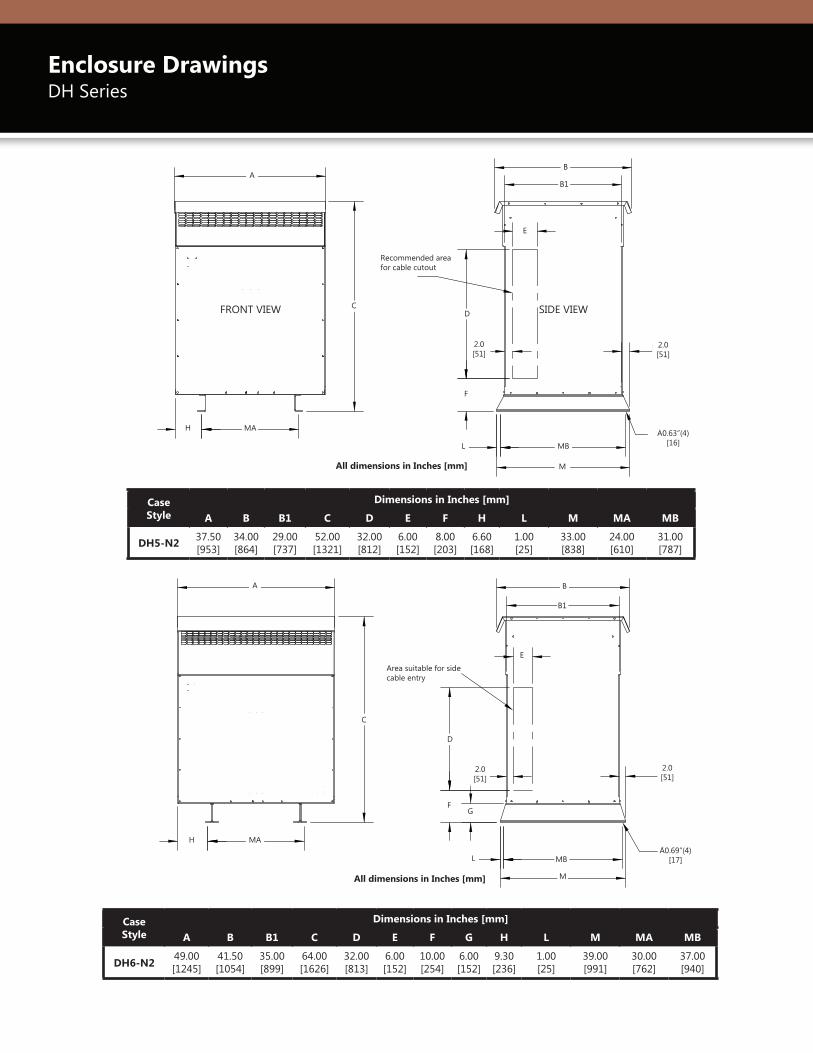
Enclosure DrawingsDH Series
1Knockouts (k) sizes are actual diameters of knockout, not conduct size.
1Knockouts (k) sizes are actual diameters of knockout, not conduct size.
Case Style
Dimensions in Inches [mm]
A A1 B B1 C D E F G H K1 L MA MB
DH1-N2 21.50 [546]
18.80[478]
20.10 [511]
15.00 [381]
22.00 [559]
12.60 [320]
2.00 [51]
7.00 [178]
8.30 [211]
6.60 [168] 1.4X1.8 [35x44] K.O 2.60
[66]20.00 [508]
9.00 [229]
DH2-N2 25.80 [655]
23.30 [592]
23.80 [605]
18.00 [457]
28.80 [732]
17.10 [434]
2.00 [51]
8.00 [203]
10.30 [262]
8.60 [218] 1.8X2.5 [44x64] K.O 3.80
[97]24.60 [625]
9.00 [229]
Case Style
Dimensions in Inches [mm]
A B B1 C D E H K1 L M MA MB
DH3-N2 28.30 [719]
27.00 [686]
22.00 [559]
36.00 [914]
22.00 [559]
3.00 [76]
12.00 [305] 2.0 X 3.0 [51X76] K.O. 1.00
[25]26.00 [660]
21.50 [546]
24.00 [610]
DH4-N2 31.50 [800]
29.50 [749]
24.50 [622}
44.50 [1130]
27.50 [699]
3.00 [76]
14.50 [368] 2.0 X 3.0 [51X76] K.O. 1.00
[25]28.50 [724]
23.50 [597]
26.50 [673]
FRONT VIEW All Dimensions in inches[mm]
MA
A
C
L MB
B
B1
H
D
E
M
[51]2.0
[16]Ă0.63" (4)
K
SIDE VIEW
FRONT VIEWAll Dimensions in inches[mm]
MA
A1
A
MA
F
G
C
[13]0.50KEY HOLESLOT(4)
L MB
B
B1
H
D
E
K
SIDE VIEW
[16]Ă0.63" (4)
FRONT VIEW SIDE VIEW
All dimensions in Inches [mm]
A
MA
A1
F
G
MA
C
0.5 [13] KEY HOLE SLOT(4)
B
B1
H
D
K
E
L MB A0.63”(4) [16]
FRONT VIEW SIDE VIEW
All dimensions in Inches [mm]
A
C
MA
B
B1
H
D
KE
L MB
M
A0.63”(4) [16]
2.0 [51]
6Data subject to change without notice.
Enclosure DrawingsDH Series
Case Style
Dimensions in Inches [mm]
A B B1 C D E F H L M MA MB
DH5-N2 37.50 [953]
34.00 [864]
29.00 [737]
52.00 [1321]
32.00 [812]
6.00 [152]
8.00 [203]
6.60 [168]
1.00 [25]
33.00 [838]
24.00 [610]
31.00 [787]
Case Style
Dimensions in Inches [mm]
A B B1 C D E F G H L M MA MB
DH6-N2 49.00 [1245]
41.50 [1054]
35.00 [899]
64.00 [1626]
32.00 [813]
6.00 [152]
10.00 [254]
6.00 [152]
9.30 [236]
1.00 [25]
39.00 [991]
30.00 [762]
37.00 [940]
All Dimensions in inches[mm]
H MA
A
CD
F
[51]2.0
E
L MB
B
B1
M
[51]2.0
FRONT VIEW
RECOMMENDEDAREA FOR CABLE
CUTOUT
SIDE VIEW
[16]Ă0.63" (4)
All Dimensions in inches[mm]
H MA
C
A
FRONT VIEW
[51]2.0
E
D
F
L MB
M
[51]2.0
B
B1
G
[17]Ă0.69" (4)
AREA SUITABLE FORSIDE CABLE ENTRY
SIDE VIEW
FRONT VIEW SIDE VIEW
A
C
H MA
Recommended area for cable cutout
B
B1
E
D
F
L MB
M
2.0 [51]
2.0 [51]
A0.63”(4) [16]
A
H MA
C
Area suitable for side cable entry
B
B1
E
D
FG
L MB
M
A0.69”(4) [17]
2.0 [51]
2.0 [51]
All dimensions in Inches [mm]
All dimensions in Inches [mm]
7Data subject to change without notice.
Case Style
Dimensions in Inches [mm]
A B B1 C D E F H L M MA MB
DH5-N2 37.50 [953]
34.00 [864]
29.00 [737]
52.00 [1321]
32.00 [812]
6.00 [152]
8.00 [203]
6.60 [168]
1.00 [25]
33.00 [838]
24.00 [610]
31.00 [787]
Case Style
Dimensions in Inches [mm]
A B B1 C D E F G H L M MA MB
DH6-N2 49.00 [1245]
41.50 [1054]
35.00 [899]
64.00 [1626]
32.00 [813]
6.00 [152]
10.00 [254]
6.00 [152]
9.30 [236]
1.00 [25]
39.00 [991]
30.00 [762]
37.00 [940]
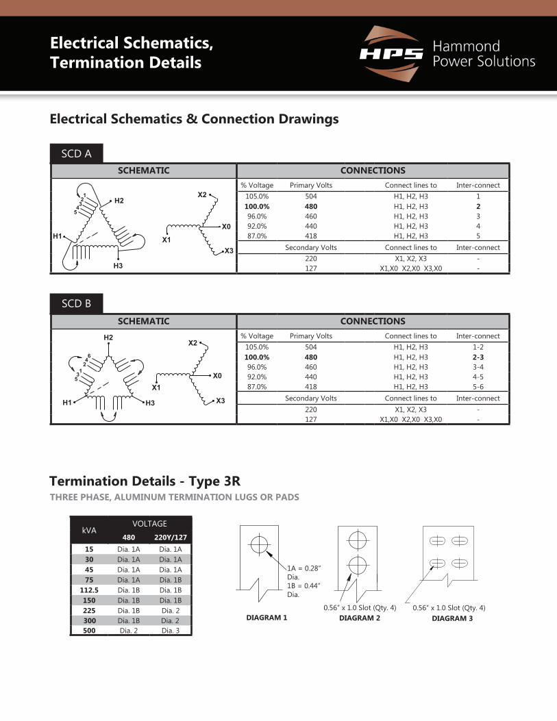
Electrical Schematics, Termination Details
SCHEMATIC CONNECTIONS% Voltage Primary Volts Connect lines to Inter-connect
105.0% 504 H1, H2, H3 1-2100.0% 480 H1, H2, H3 2-396.0% 460 H1, H2, H3 3-492.0% 440 H1, H2, H3 4-587.0% 418 H1, H2, H3 5-6
Secondary Volts Connect lines to Inter-connect220 X1, X2, X3 -127 X1,X0 X2,X0 X3,X0 -
SCD B
SCHEMATIC CONNECTIONS% Voltage Primary Volts Connect lines to Inter-connect
105.0% 504 H1, H2, H3 1100.0% 480 H1, H2, H3 296.0% 460 H1, H2, H3 392.0% 440 H1, H2, H3 487.0% 418 H1, H2, H3 5
Secondary Volts Connect lines to Inter-connect220 X1, X2, X3 -127 X1,X0 X2,X0 X3,X0 -
SCD A
H2
H1
H3
X1
X2
X0
X3
12
345
H2
H1 H3
X0X1
X2
X3
64
213
5
Electrical Schematics & Connection Drawings
THREE PHASE, ALUMINUM TERMINATION LUGS OR PADS
kVAVOLTAGE
480 220Y/12715 Dia. 1A Dia. 1A30 Dia. 1A Dia. 1A45 Dia. 1A Dia. 1A75 Dia. 1A Dia. 1B
112.5 Dia. 1B Dia. 1B150 Dia. 1B Dia. 1B225 Dia. 1B Dia. 2300 Dia. 1B Dia. 2500 Dia. 2 Dia. 3
DIAGRAM 1 DIAGRAM 30.56” x 1.0 Slot (Qty. 4)0.56” x 1.0 Slot (Qty. 4)
1A = 0.28” Dia. 1B = 0.44” Dia.
DIAGRAM 2
Termination Details - Type 3R

8Data subject to change without notice.
If wall and/or ceiling mounting is desired for a transformer, optional mounting kits can be ordered separately. These mounting kits are NOT available for all enclosure case styles.Therefore, it is important that you confirm your enclosure case style, then use the selection table to the right to determine if A) a mounting kit is available and B) determine the correct HPS “Mounting Kit” part number that you must order. One kit is required for each transformer.
Note: Some of the mounting kits can be used for both wall and ceiling mount, while others are for wall mounting only. The table indicates which mounting methods are available for each kit. The DW3 wall/ceiling mounting kit also includes a drip plate. The DW3 wall/ceiling mounting kit is only designed for units up to 1000 pounds (453 kg) maximum.
If it is intended to wall and/or ceiling mount an enclosure that does not have a wall/ceiling mount kit available, considerations must be made to mechanically support the transformer safely and to install per the local building code. A drip plate must be provided beneath the enclosure per UL 1561 and CSA C22.2 No. 47.
EnclosureWall Mount
AvailableCeiling Mount
Available
HPS Mounting Kit
P/N
DH1-N1 YES YES DH1DP
DH2-N2 YES YES DH2DP
DH3-N2 YES YES DW3
DH4-N2 NO NO N/A
DH5-N2 NO NO N/A
DH6-N2 NO NO N/A
WALL MOUNTING KITS
Wall Mounting Kits
The DH1-N2 and DH2-N2 enclosures are designed with integral wall mounting capabilities. However, when you wall mount them, you must also install the bottom drip plate as shown below. The “MB” dimensions listed in the table below indicate the location for the wall mounting hardware.
For ceiling mounting of the DH1-N2 and DH2-N2, refer to the “MA” dimensions listed in the table below and hang the enclosure using appropriate sized ceiling hanger rods. However, you must be sure to install the bottom drip plate to the bottom of the enclosure, then bring the hanger rod down through both the enclosure bottom mounting holes, through the drip plate mounting holes, and install mounting hardware.
Note: Do not ceiling mount either the DH1-N2 and DH2-N2 enclosures without installing the bottom drip plate. All mounting hardware should be rated Grade 8 or higher.
Mounting Kit P/N
Enclosure Style
MA Dimension Inch [mm]
MB Dimension Inch [mm]
DH1DP DH1-N2 9.00 [229]
7.00 [178]
DH2DP DH2-N2 9.00 [229]
8.00 [203]
DH1DP and DH2DP WALL/CEILING MOUNTING KITS
Bottom Drip Plate(DH1DP or DH2DP)
9Data subject to change without notice.
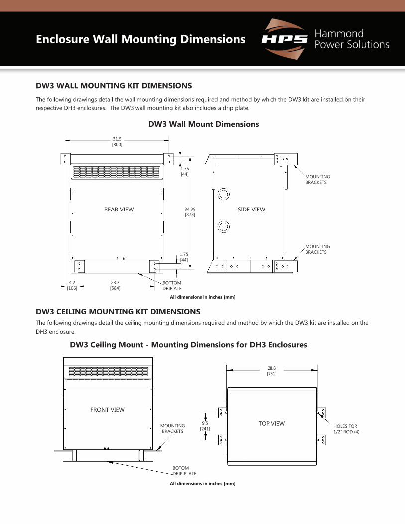
Enclosure Wall Mounting Dimensions
DW3 WALL MOUNTING KIT DIMENSIONS
The following drawings detail the wall mounting dimensions required and method by which the DW3 kit are installed on their respective DH3 enclosures. The DW3 wall mounting kit also includes a drip plate.
DW3 CEILING MOUNTING KIT DIMENSIONSThe following drawings detail the ceiling mounting dimensions required and method by which the DW3 kit are installed on the DH3 enclosure.
DW3 Wall Mount Dimensions
DW3 Ceiling Mount - Mounting Dimensions for DH3 Enclosures
REAR VIEW
1.75 [44]
All dimensions in inches [mm]
All dimensions in inches [mm]
SIDE VIEW
MOUNTING BRACKETS
MOUNTING BRACKETS
4.2 [106]
23.3 [584]
31.5 [800]
34.38 [873]
BOTTOM DRIP ATF
MOUNTING BRACKETS
BOTOM DRIP PLATE
FRONT VIEW
TOP VIEW HOLES FOR 1/2” ROD (4)
28.8 [731]
9.5 [241]
1.75 [44]
10Data subject to change without notice.
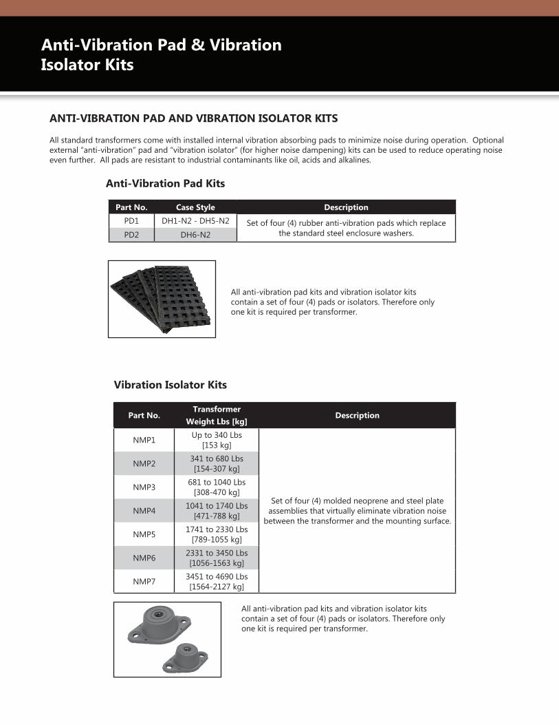
All standard transformers come with installed internal vibration absorbing pads to minimize noise during operation. Optional external “anti-vibration” pad and “vibration isolator” (for higher noise dampening) kits can be used to reduce operating noise even further. All pads are resistant to industrial contaminants like oil, acids and alkalines.
ANTI-VIBRATION PAD AND VIBRATION ISOLATOR KITS
Part No. Case Style Description
PD1 DH1-N2 - DH5-N2 Set of four (4) rubber anti-vibration pads which replace the standard steel enclosure washers.PD2 DH6-N2
Part No.Transformer
Weight Lbs [kg]Description
NMP1 Up to 340 Lbs [153 kg]
Set of four (4) molded neoprene and steel plate assemblies that virtually eliminate vibration noise
between the transformer and the mounting surface.
NMP2 341 to 680 Lbs [154-307 kg]
NMP3 681 to 1040 Lbs [308-470 kg]
NMP4 1041 to 1740 Lbs [471-788 kg]
NMP5 1741 to 2330 Lbs [789-1055 kg]
NMP6 2331 to 3450 Lbs [1056-1563 kg]
NMP7 3451 to 4690 Lbs [1564-2127 kg]
All anti-vibration pad kits and vibration isolator kits contain a set of four (4) pads or isolators. Therefore only one kit is required per transformer.
All anti-vibration pad kits and vibration isolator kits contain a set of four (4) pads or isolators. Therefore only one kit is required per transformer.
Anti-Vibration Pad Kits
Vibration Isolator Kits
Anti-Vibration Pad & Vibration Isolator Kits

11Data subject to change without notice.
Other Low Voltage Distribution Transformers
HPS TRAFOLEONTM
Energy Efficient Distribution Transformer HPS TrafoLeon Series has been designed for the Mexico market based on industry leading technologies and materials to meet your most demanding aplications. These energy efficient distribution transformers are compliant to NMX-J-351-ANCE-2016 efficiency standard. Standard features include:
• Complies with NMX-J-351-1-ANCE-2016 standard• 60 Hz frequency• Ratings from 15 to 333 kVA single phase and 15 to 1000 kVA three phase • An extensive standard offering complimented by a wide variety of custom
products available• Copper and aluminum available• Standard 150 deg C temperature rise and 220 deg C insulation class (optional low
temp. rise units available)• Custom sizes, ratings and styles available upon request• Standard type 3R enclosure • Optional K-factor units available
HPS SENTINELTM
Energy Efficient Distribution TransformerHPS offers three standard lines of energy efficient low voltage distribution transformers that meet or exceed U.S. Department of Energy (DOE) 10 CFR Part 431 efficiency standards and Canadian Energy Efficiency Regulations SOR/94-651 efficiencies - NRCan 2019. Standard features include:
• Meets DOE 2016 and NRCan 2019 efficiency standards • Single phase ratings from 15 kVA to 333 kVA and three phase from 15 kVA to
1000 kVA (custom ratings available upon request)• Copper and aluminum available• UL Listed and CSA Certified• Type 3R enclosure• Pre-installed lugs (up to 270 Amps)• General purpose, k-factor and harmonic mitigating available
In addition to HPS Express L we also offer other low voltage distribution transformers to meet your applications and efficiency needs.

EXPLBROJuly 2021
EUROPE
MEXICO
CANADA UNITED STATES
EMEA (Sales Office)Hammond Power Solutions SpATel: +49 (152) [email protected]
UNITED STATESHammond Power Solutions1100 Lake StreetBaraboo, Wisconsin 53913-2866Tel: (608) 356-3921Fax: (608) 355-7623Toll Free: [email protected]
CANADAHammond Power Solutions595 Southgate DriveGuelph, Ontario N1G 3W6Tel: (519) 822-2441Fax: (519) 822-9701Toll Free: [email protected]
ASIAHammond Power Solutions Pvt. Ltd. D. No. 5-2/222/IP/B, II-Floor, Icon PlazaAllwyn X-Roads, Miyapur, Hyderabad 500 049Tel: [email protected]
MEXICOHammond Power SolutionsAv. No. 800, Parque Industrial Guadalupe Guadalupe, NL, Mexico, C.P. 67190. Tel: (819) [email protected]
ASIA
www.hammondpowersolutions.com


