13
Update of EXT Stripline BPM Electronics with LCLS-style Digital BPM Processors Glen White, with slides by Steve Smith 15 December 2009 ATF2
| Date post: | 01-Jan-2016 |
| Category: |
Documents |
| Upload: | jack-sweeney |
| View: | 19 times |
| Download: | 1 times |

Update of EXT Stripline BPM Electronics with LCLS-style
Digital BPM Processors
Glen White, with slides by Steve Smith
15 December 2009
ATF2
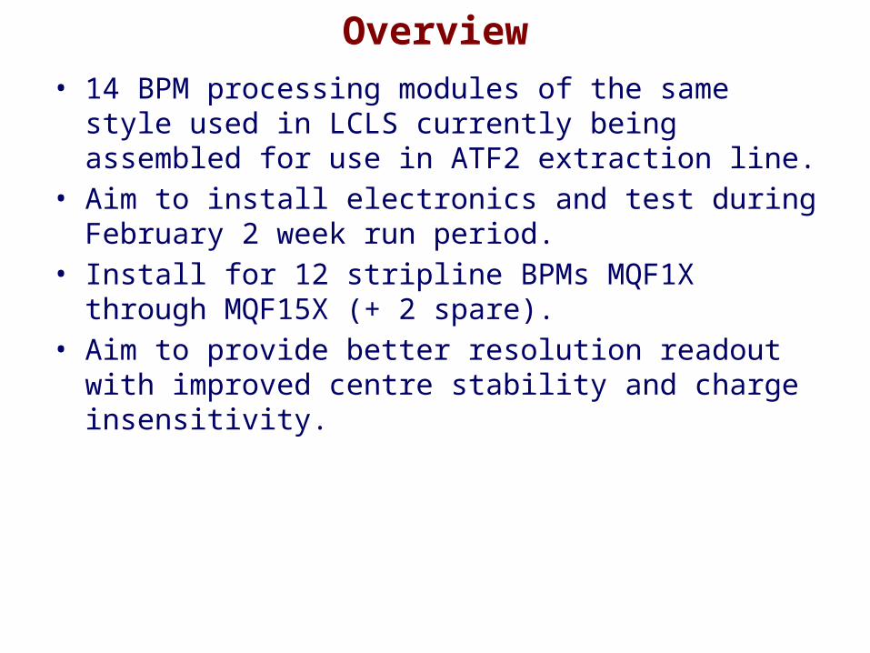
Overview• 14 BPM processing modules of the same style used in
LCLS currently being assembled for use in ATF2 extraction line.
• Aim to install electronics and test during February 2 week run period.
• Install for 12 stripline BPMs MQF1X through MQF15X (+ 2 spare).
• Aim to provide better resolution readout with improved centre stability and charge insensitivity.

ATF2 Extraction Line BPMs• 12 Stripline BPMs in ATF2 extraction line
– 3 types:a) 3 each with L= 40 mm, d=27mm
b) 5 each with L= 40 mm, d=37mm
c) 4 each with L= 120 mm, d=27mm
• Angular coverage 70 degree/ strip• Charge range 1-10 x 109 e- / bunch• Single bunch or 3 – 20 bunches at 357 MHz separation• Requirements:
– Several-micron resolution– Good stability over
bunch charge

LCLS Stripline BPMs
• ~ 200 BPMs• Most common type has L= 100 mm, d=24mm• Angular coverage 26 degree/ strip• Charge range 1.2 - 16 x 109 e- / bunch• Single bunch• Requirements:
– < 5 micron resolution at 200 pC– Good stability over bunch charge
• Similar signal, similar requirements

Estimate Resolution by Comparison
ATF2
• Length ≥ 40 mm• Angular coverage 70 deg• Diameter 27 - 37 mm• Greater coverage, less
length comparable resolution
Larger diameter BPMs will have slightly worse resolution
LCLS• Length = 100 mm • Angular coverage 26 deg• Diameter 24 mm
Resolution:Proportional to diameterInversely to length, coverage:
6
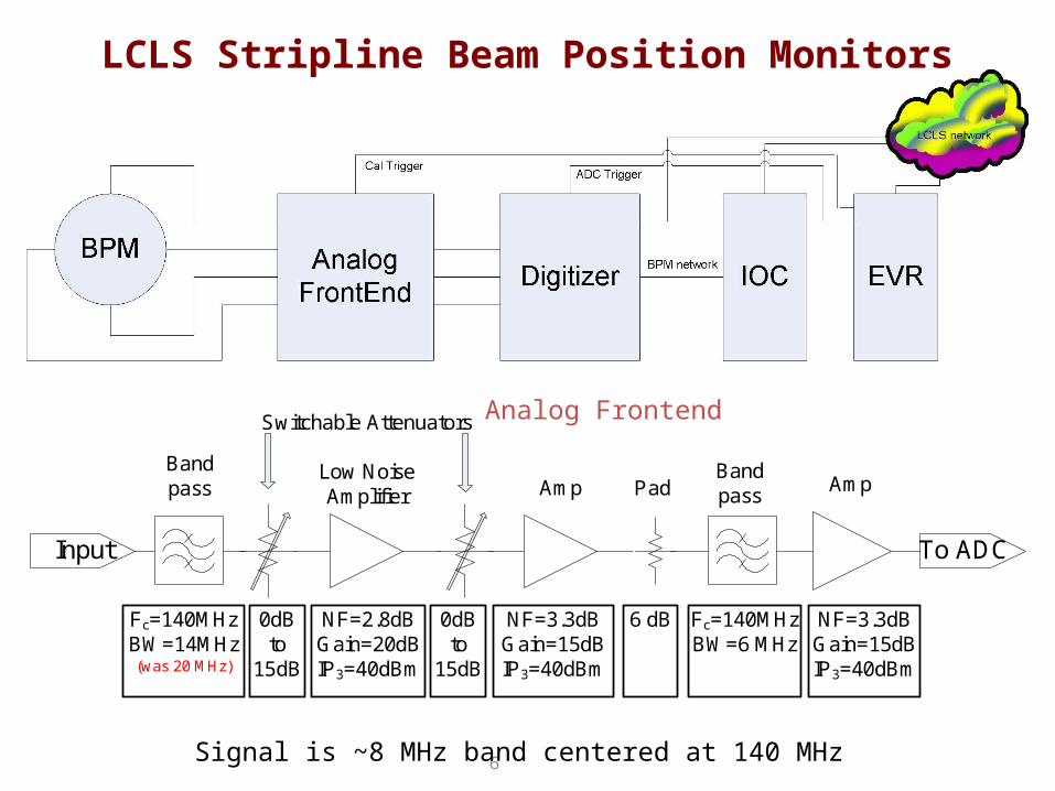
LCLS Stripline Beam Position Monitors
Input
Low Noise Amplifier
AmpBandpass Amp
To ADC
Bandpass
NF=2.8dBGain=20dBIP3=40dBm
Fc=140MHzBW=14MHz(was 20 MHz)
Fc=140MHzBW=6 MHz
NF=3.3dBGain=15dBIP3=40dBm
NF=3.3dBGain=15dBIP3=40dBm
Switchable Attenuators
0dBto
15dB
0dBto
15dB
6 dB
Pad
Analog Frontend
Signal is ~8 MHz band centered at 140 MHz

BPM raw digitized waveforms. Sampling frequency 120 MHz.
Algorithm• IOC (VME processor)
calculates position and beam charge from ADC waveforms
• Position:– Estimate amplitude from
each strip• Vi = rms(ADCi)
• Correct for calibrated gain ratio
• X = R/2 /

Online Calibration• Launch tone burst into one strip• Receive on adjacent strips• Estimate amplitudes as above• Calculate gain ratio• Correct raw beam amplitudes• Repeat between pulses
Calibrator tone burst detected on adjacent strips
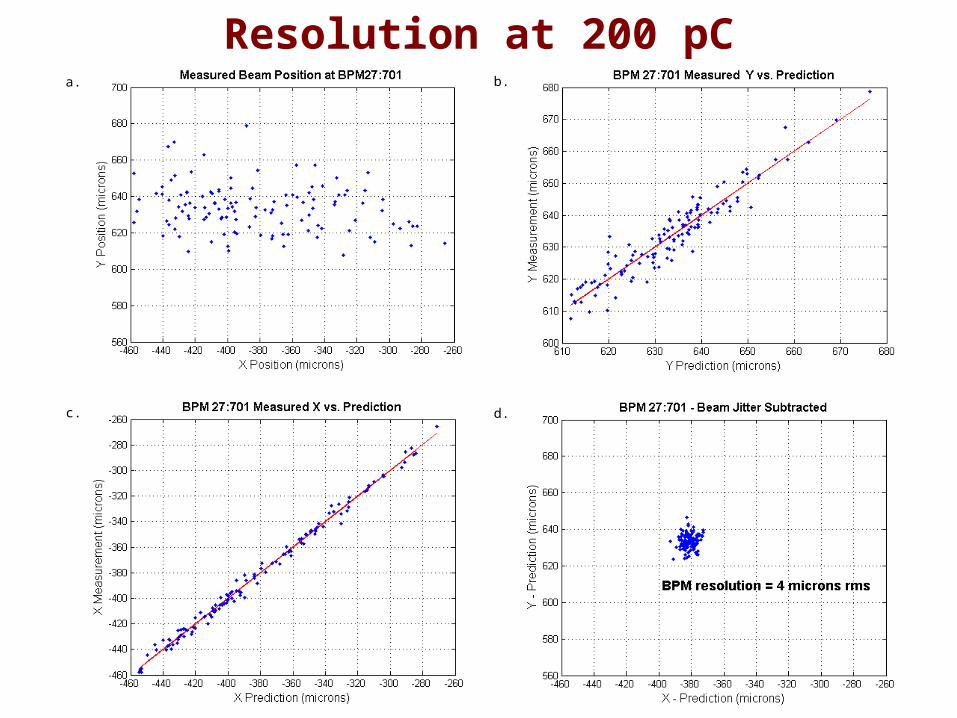
Resolution at 200 pCb.a.
c. d.
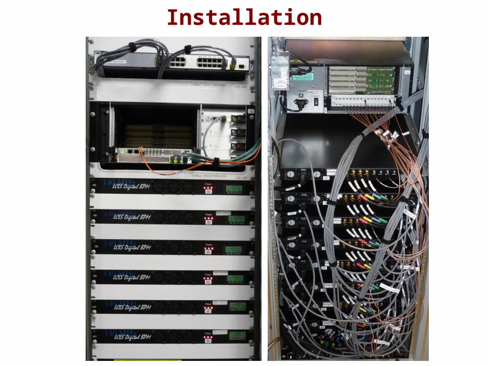
Installation

Online Diagnostic Displays

Configuration for ATF2• Processor chassis containing Analog Frontend.• Included:
– Analog Frontend– Clock
• Functions:– All analog processing – Including calibration
• ADC (6 * 8-channel 14-bit 105MHz SIS3301 VME cards)• Digital processing (EPICS db)• Control interface (RS232 via tcp/ip serial hub)
– Control via EPICS IOC– Set attenuators– Set up calibration
• Trigger signal distribution and control.
EP I CS
IOC
Triggers
Analog Front End (*12) 16 Port
Tcp/ipSerial hub
BPMs(*12)
Digitisers (*6)
Network
VME

ATF2 Multibunch Operation• BPM averages over train in multibunch mode• Resolution is approximately the same as single bunch
for the same charge per bunch• Unless bunch spacing is near a subharmonic of BPM
processing frequency


