44
UPDM Technical Workshop Tom Coolidge and Tom DeWitte

UPDM Technical WorkshopTom Coolidge and Tom DeWitte

Desktop Devices
UPDM Online Content and Services
ArcGIS Platform
Web
PODS APR*
* Collaborative effort of the PODS Association & Esri
Enterprise DataPortal
Location Referencing Connectivity Modeling

UPDM Background, Drivers, and Concepts

About UPDM
Esri’s UPDM is a geodatabase data model template for operators of pipe networks in the gas and hazardous liquids industries. UPDM is a
moderately normalized data model
that explicitly represents each physical component of a pipe network from the wellhead to the customer meter, terminal or delivery point, in a single database table object.

Why UPDM?
Esri solutions are based on UPDM.
APR is home‐based on UPDM. An alternative data model is in development by the PODS Association,
Partners are developing on UPDM.
DNV GL
G2/Eagle Information Mapping
Geonamic Systems
New Century Software
Novara GeoSolutions

UPDM Evolution
Traces its heritage to the first release of the Gas Data Model in 2001, being renamed now to reflect broadened scope
Partners and customers always have played a role in the development of the Gas Data Model, and they are playing an active role in the evolution of UPDM
The latest release of UPDM occurred October, 2015.

Business Drivers for UPDM
Enable vertically integrated gas companies that have distribution, transmission and gathering pipe networks to use one data model
The trend is to a smaller number of bigger gas companies
More gas companies will have integrated systems including a combination of distribution, transmission and gathering assets
How those high pressure distribution pipes are operated and how they are regulated will differ
Enable location referencing and connectivity modeling to operate on the same geodatabase

Business Drivers for UPDM
Simplify staff training
Single workflow for maintaining distribution, transmission and gathering asset data
Better manage HP Distribution pipe (> 20% SMYS)
Improve staff efficiency and productivity

Technical Drivers to Evolve UPDM
Represent “Best practice” for managing data in a Geodatabase
Align with ArcGIS Pro and advances being developed in the ArcGIS Pro environment
Align with ArcGIS Location Referencing for Pipelines extension
Improve scalability and performance for larger transmission pipe networks using fully normalized data models (Performance and scalability issues not currently existing in the gas distribution user community)

UPDM Support
Esri has actively maintained and enhanced the Gas Data Model through the years, and that will continue with UPDM.

Geodatabase Concepts and UPDM
All events stored as features
Connectivity model used to maintain physical assets
Linear referencing model used to maintain transmission integrity data
Metadata managed as part of feature (Editor Tracking & Archiving)
Documents managed with Attachments
Time Aware (be able to view system at different states in time)

Improving Performance Through Better Data ManagementTransmission – Viewing Pipe Segments
Database Activity with Legacy Data Model• 1 – Geodatabase• 3 – Tables/Featureclasses queried
66% Reduction in SQL queries in the database
Database Activity with UPDM• 1 Geodatabase• 1 – Featureclass queried

Improving Performance Through Better Data ManagementTransmission and Distribution – Viewing Pipe Segments
Database Activity with Legacy Data Model• 2 – Geodatabases• 4 – Tables/Featureclasses queried
75% Reduction in SQL queries in the database
Database Activity with UPDM• 1 Geodatabase• 1 – Featureclass queried

Improving Scalability Through Data Storage EfficiencyTransmission
PipeSegment
PipeSegmentAudit
Pipes
Valve
ValveAudit
Valves
Legacy Data Models UPDM
50% Reduction in Records stored in the database

Improving Scalability Through Data Storage EfficiencyTransmission and Distribution
PipeSegment
PipeSegmentAudit Pipes
Legacy Data Models UPDM
33% Reduction in Records stored in the database
Mains
66% Reduction in tables stored in the database

UPDM Overview

UPDM – A Geodatabase Template Data Model
Esri strives to build template data models
Template data models jump start your geodatabase
design
Most users
start with these design templates
then refine and extend them to meet their specific
needs and requirements

UPDM System Tables – Hierarchy
An operating pipe system can be viewed as a hierarchical network of interconnected pressure system and emergency isolation zones. The Utility and Pipeline Data Model provides the ability to organize and manage this hierarchy as well as manage multiple systems within one data model. UPDM provides a basic hierarchy of the pipe system. This hierarchy provides four basic tiers.
A single company can be composed of multiple systems. A single pipe system can be composed of multiple pressure systems. Within a single pressure system, there can be multiple emergency isolation systems. A single emergency isolation system is composed of multiple pipe segments, service lines, gas valves, etc.

UPDM System Tables – Editing Configuration
The ArcGIS for Gas Utilities solution includes a set of gas editing tools for ArcGIS for Desktop to streamline the maintenance of the physical assets of the pipe network These tables are required to support some of the advanced capabilities of the ArcGIS for Gas Utilities editing tools.
TableDynamicValue
TableGenerateId

UPDM System Tables – ArcGIS Pipeline Referencing
The ArcGIS Pipeline Referencing extension (APR) is a set of tools provided by Esri to create and maintain the spatial relationship between event features such as those listed in the “integrity” section of UPDM and the centerline upon which they act. These feature classes and tables are to help with the management of information required to maintain APR.
Point feature class P_CalibrationPoints
Line feature class P_Centerline
TableP_Centerline_Sequence
Line feature class P_ContinuousNetwork
Line feature class P_StationSeriesNetwork
Line feature class P_Redline

UPDM Physical Components – Pipes
Pipes are the linear assets through which a liquid or gas is transported. These pipes are modeled as complex edges within the geometric network so other assets (valves, fittings, etc.) can be connected to them without having to split the linear asset.
Simple edge feature class P_Service
Subtypes are Bare Steel, Coated Steel, Ductile Iron, Copper, Cast Iron, Wrought Iron, Plastic PVC, Plastic PE, Plastic ABS, Plastic Other
Simple edge feature class P_GatheringFieldPipe
Subtypes are Water, Steam, Waste Water
Simple edge feature class P_Pipes
Subtypes are Bare Steel, Ductile Iron, Wrought Iron, Coated Steel, Copper, Plastic PE, Cast Iron, Plastic PVC, Plastic Other, Composite, Plastic ABS, Reconditioned Cast Iron

UPDM Physical Components – Flow Control Devices
Flow control devices are physical assets in a gas system that have the ability to impact the flow of liquids and gas through the pipe system. These devices are typically modeled as simple junction point features within the geodatabase.
Simple junction feature class P_ControllableFitting
Subtypes are Short Stop, Three‐Way Tee
Simple junction feature class P_CompressorStation
Simple junction feature class P_PumpStation
TableP_Regulator
Simple junction feature class P_ExcessFlowValve
Simple junction feature class P_Valve
Simple junction feature class P_RegulatorStation
Simple junction feature class P_TownBorderStat ion
Simple junction feature class P_ReliefValve
Point feature class P_Wellhead
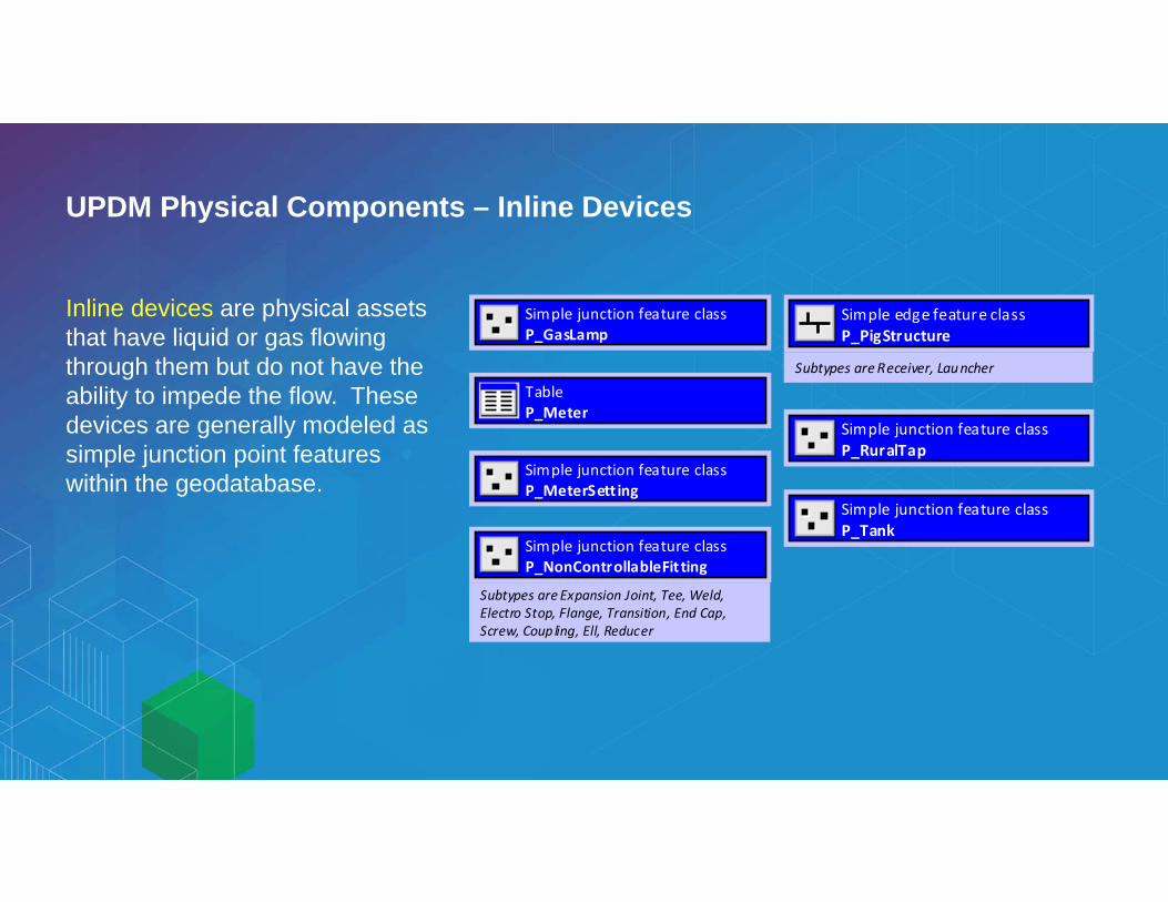
UPDM Physical Components – Inline Devices
Inline devices are physical assets that have liquid or gas flowing through them but do not have the ability to impede the flow. These devices are generally modeled as simple junction point features within the geodatabase.
Simple junction feature class P_NonControllableFitting
Subtypes are Expansion Joint, Tee, Weld, Electro Stop, Flange, Transition, End Cap, Screw, Coupling, Ell, Reducer
Simple junction feature class P_MeterSett ing
TableP_Meter
Simple junction feature class P_GasLamp
Simple junction feature class P_Tank
Simple junction feature class P_RuralTap
Simple edge feature class P_PigStructure
Subtypes are Receiver, Launcher

UPDM Physical Components – Connected Devices
Connected devices are those assets that are physically connected to the pipe system but do not have liquids or gas flowing through the device.
Point feature class P_Coupon
Simple junction feature class P_Drip
Simple junction feature class P_PressureMonitoringDevice

UPDM Physical Components – Structures
Structures are assets that are not physically connected to the pipe system. These assets support the pipe system by improving the structural integrity or improving the safety of the neighboring community. These assets are not part of the geometric network for the pipe system.
Line feature class P_PipeCasing
Point feature class P_PipelineMarker
Polygon feature class P_Vault
Polygon feature class P_StationStructure

UPDM Physical Components – Conditioning Equipment
Conditioning equipment includes devices whose purpose is to physically change the liquid or gas flowing through the pipe system. These changes can include the removal of foreign content, addition of odorant, changing the commodity temperature, or injection of chemicals to prevent hydrate formation. These devices are physically connected to the pipe system; therefore, they are modeled as part of the geometric network. Within the geometric network, they are modeled as simple junction point features.
Simple junction feature class P_Scrubber
Simple junction feature class P_LineHeater
Simple junction feature class P_Odorizer
Subtypes are Bypass, Pulse, Wick, Injection Pump, Rural Tap Odorizer
Simple junction feature class P_Strainer
Simple junction feature class P_DehydrationEquip

UPDM Physical Components – Cathodic Protection System
Cathodic protection is a mechanism by which an electrical current is used to prevent or control corrosion in underground metallic pipe mains. There are several devices involved in a cathodic protection system including sacrificial anodes (metallic device that is allowed to corrode or is “sacrificed” to protect the metal in the pipe from corroding), rectifiers (the source of the electrical current), and test points (locations along the pipe used to test the current status of the system). These cathodic devices prevent corrosion of the metallic components within a pipe system. Common metallic pipe system components protected by a cathodic protection system are mains, valves, and fittings. The feature classes listed in this section are to help with the management of a cathodic protection system.
Simple junction feature class P_CPRectifier
Simple junction feature class P_CPTestPoint
Simple edge feature class P_CPRectifierCable
Simple junction feature class P_CPBondJunction
Simple junction feature class P_CPAnode
Simple edge feature class P_CPBondWire
TableP_CPSystem

UPDM Physical Components – Legacy Abandoned Assets
The methods available to model abandoned and removed gas components have evolved considerably with the addition of the ability to manage history within the ArcGIS products. The implementation of a workflow to manage the abandonment or removal of gas components can now be managed with the core ArcGIS capabilities; therefore, this section can be considered optional.
Some organizations may still want to use the legacy method of writing the abandoned or removed gas component to a separate feature class or table. The feature classes and tables defined in this section represent how to model abandoned and removed gas components if this legacy method is utilized.
Point feature class P_AbandonedDevice
Line feature class P_AbandonedPipe
TableP_AbandonedRemovedDevice
TableP_AbandonedRemovedPipe

UPDM Activity and Integrity – Inspections
Inspections are repetitive activities that an organization performs as part of the operation of a pipe system. Many of these inspections are required by US DOT regulations. The feature classes and table objects listed in this section help with the management of the information collected by field staff as part of the inspection process.
TableP_CasingInspection
TableP_CPBondInspection
TableP_CPRectifierInspect ion
TableP_CPTestPointReading
TableP_CrossingInspect ion
TableP_ElectricSurvey
Line feature class P_ExcavationDamage
TableP_IsolatedPipeInspection
Point feature class P_GasLeakIn spection
Point feature class P_InspectionNote
Line feature class P_ExposedPipeInspection
Line feature class P_InspectionRange
Polygon feature class P_LeakSurveyArea
TableP_LineValveInspect ion
Point feature class P_WorkOrder
TableP_RegulatorInspection
TableP_ReliefValveInspection
TableP_StationVisualInspection
TableP_StrainerInspection
TableP_ValveInspect ion

UPDM Activity and Integrity – Maintenance
Maintenance is the activity an organization undertakes to keep the pipe system in production. In the process of maintaining the system, additional information is often discovered or captured. The feature classes listed in this section represent those layers that are not considered part of the organization’s inspection program but are part of the organization’s maintenance program.
Simple junction feature class P_SqueezeOff
Point feature class P_IdentifiedIssue
Point feature class P_GasLeak
Line feature class P_LeakRepairs
Subtypes are Corrosion, Other, Natural Forces, Excavation Damage, Material Fa ilure, Other Outside Force, Incorrect Operations, Equipment Failure
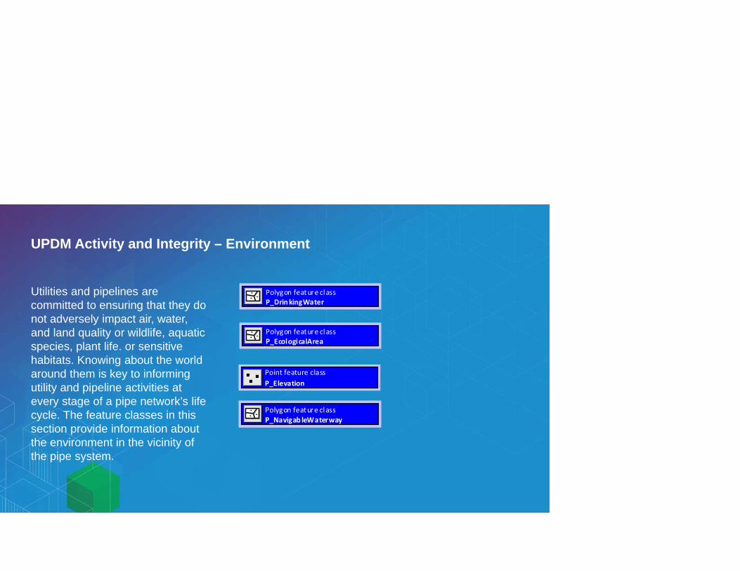
UPDM Activity and Integrity – Environment
Utilities and pipelines are committed to ensuring that they do not adversely impact air, water, and land quality or wildlife, aquatic species, plant life. or sensitive habitats. Knowing about the world around them is key to informing utility and pipeline activities at every stage of a pipe network’s life cycle. The feature classes in this section provide information about the environment in the vicinity of the pipe system.
Polygon feature class P_DrinkingWater
Polygon feature class P_EcologicalArea
Point feature class P_Elevation
Polygon feature class P_Navigab leWaterway

UPDM Activity and Integrity – Determining Consequence
Determining Consequence featureclassesdescribe United States locations and structures, as defined at 49 CFR 192.903 and 49 CFR 192.5. These supporting datasets help to determine gas transmission pipeline high consequence area (HCA), and DOT pipeline class.
Polygon feature class P_HighPopulatedArea
Polygon feature class P_OtherPopulatedArea
Polygon feature class P_OutsideArea
Point feature class P_StructurePoint
Polygon feature class P_StructureFootPoint

UPDM Activity and Integrity – Inline Inspection
Inline inspection (ILI) employing smart pigs is used to assess the integrity of pipelines from the inside of the pipe. The data recorded by the smart pig is retrieved for analysis and reporting and is a critical component of ongoing pipeline integrity programs. Some of this information is required by federal and state regulations. Other data is needed to understand the state of the gas system. The information defined in this section will help manage the inline inspection data to ensure the relativity and integrity of the pipeline.
Line feature class P_InlineInspection
Point feature class P_ILIGroundRefMarkers
Point feature class P_ILISurveyGroup
Point feature class P_ILISurveyReadings
Line feature class P_ILIInspectionRange

UPDM Activity and Integrity – Integrity
Once a gas system has been constructed and put into production, it is the gas utility’s responsibility to maintain the gas system as a safe and reliable transportation system for natural gas. Ensuring that a gas system is safe and reliable requires a significant amount of data. Some of this information is required by federal and state regulations. Other data is needed to understand the state of the gas system. The information defined in this section is to manage the data collected to ensure that the production gas system is safe and reliable.
Point feature class P_AnomalyGroup
Point feature class P_Anomaly
Line feature class P_ConsequenceSegment
Subtypes are Installed, Calcu la ted, Approved
Line feature class P_CouldAffectSegment
Point feature class P_DASurveyReadings
Point feature class P_DocumentPoint
Line feature class P_CenterlineAccuracy
Line feature class P_DOTClass
Polygon feature class P_HighConsequenceArea
Line feature class P_MAOPCalcRange
Line feature class P_OperatingPressureRange
Line feature class P_PipeCrossing
Subtypes are P ipe Utility, Wire Utility, Transportation, Topographic
Line feature class P_PipeExposure
Line feature class P_TestPressureRange

UPDM Activity and Integrity – Mapping
The purpose of the feature classes in this section is to aid in the visual/cartographic presentation of the gas system. This includes feature classes to aid in the creation of paper representations of the gas system, as well as feature classes to aid in the visual representation of information. Point feature class
P_PipeJobSeparator
Polygon feature class P_CapitalProject
Polygon feature class P_AlignmentSheet
Polygon feature class P_CPArea

What you get

Demo
UPDM Adoption

UPDM Adoption
Esri solutions are based on UPDM.
APR is home‐based on UPDM. An alternative data model is in development by the PODS Association,
Partners are developing on UPDM.
DNV GL
G2/Eagle Information Mapping
Geonamic Systems
New Century Software
Novara GeoSolutions

UPDM adoption
As of June 15, 2016, UPDM has been downloaded by non‐Esri employees 1,043 times since November 2014.
Heat map as of June 15, 2016

UPDM Early Adopters
Entity Type
Vertically Integrated Gas Companies
Gas Transmission
Hazardous Liquids Transmission
Gathering System

UPDM: The Road Ahead

Utility Network
ArcGIS Gas Network data model
polygon feature class
Utility Network Alpha 8 release, build 57xx May 23, 2016
Structural
Dom
ain
StructureJunction Unknown Muffler
point feature classpolygon feature class
StructureBoundary Unknown StationStructure Vault
StructureEdge Unknown Casing
line feature class
CathodicProtectionLine Unknown BondWire RectifierCable
line feature class
Cathodic Protection Domain
CathodicProtection Junction Unknown Connection Point
CathodicProtection Assembly Unknown
CathodicProtection SubnetLine Unknown
CathodicProtectionDevice Unknown Anode Rectifier TestPoint
point feature class
GasAssembly Unknown Compressor Station Meter Setting Pump Station Regulator Station
GasDevice Unknown Excess Flow Valve Customer Meter Utility Meter Custody Transfer Meter Critical Valve Non‐Critical Valve Pressure Reducing Valve Regulator Relief Valve Scrubber Strainer Pressure Monitoring
Device Lamp Compressor Wellhead Source Flange Temp Source Location
GasLine Unknown Bare Steel Cast Iron Coated Steel Copper Plastic PE Wrought Iron Ductile Iron Plastic PVC Composite Plastic ABS Reconditioned Cast Iron
GasSubnetLine Unknown Isolation Pressure
line feature class point feature class
GasJunction Unknown Connection Point Coupling Elbow End Cap Expansion Joint Flange Reducer Tee Transition Weld Screw Electro Stop Plastic Fusion Tank Line Heater Cooling System Odorizer Coupon Dehydration Equipment Drip
Gas Domain
point feature class
Rural Tap Town Border Station Wellhead Pigging Structure

Road Map Evolving UPDM for the Gas and Hazardous Liquids Industries
. . . Focused on Quality, User Needs, and Innovation
Crowdsourcing
Real-time
Utility networks
Location awareness
Massive 3DVector tiles
Web raster analysisAdvanced navigation
Modeling
Big data GeoAnalytics
Insights
Q4
Annual Update CycleMobile
UAV/Drone
Improvements Made Throughout Year
Distributed GISAnalytic Engines
Raster AnalyticsUser Roles
2016
2017
2018
Q4
Q2


![Bleakley_Overview UPDM for Systems Engineers DoDAF V3 DOD EA [Compatibility Mode]](https://static.documents.pub/doc/80x56/55cf973d550346d033907b26/bleakleyoverview-updm-for-systems-engineers-dodaf-v3-dod-ea-compatibility.jpg)


