UPennalizers Robocup 2013 Standard Platform League Team Description Paper Christopher Akatsuka, Alan Aquino, Sarah Dean, Yizheng He, Tatenda Mushonga, Yida Zhang, and Dr. Daniel Lee General Robotics Automation, Sensing and Perception (GRASP) Laboratory University of Pennsylvania Abstract This paper presents the organization and architecture of a team of soccer-playing Nao robots developed by University of Pennsylvania’s Robocup SPL team. It also documents the efforts gone into improving the code base for the 2013 competitive season. All sensory and motor functions are pro- totyped and run in Lua on the embedded on board processors. High-level behaviors and team coordination modules are implemented by Lua using state machines. The locomotion engine allows for omni-directional mo- tions and uses sensory feedback to compensate for external disturbances. The cognition module helps robot to detect landmarks and localize in a symmetric environment. Through the year, improvements were made across all of the various modules. 1
Transcript
UPennalizers
Robocup 2013 Standard Platform League
Team Description Paper
Christopher Akatsuka, Alan Aquino, Sarah Dean,Yizheng He, Tatenda Mushonga, Yida Zhang, and
Dr. Daniel Lee
General Robotics Automation, Sensing and Perception (GRASP)Laboratory
University of Pennsylvania
Abstract
This paper presents the organization and architecture of a team ofsoccer-playing Nao robots developed by University of Pennsylvania’s RobocupSPL team. It also documents the efforts gone into improving the code basefor the 2013 competitive season. All sensory and motor functions are pro-totyped and run in Lua on the embedded on board processors. High-levelbehaviors and team coordination modules are implemented by Lua usingstate machines. The locomotion engine allows for omni-directional mo-tions and uses sensory feedback to compensate for external disturbances.The cognition module helps robot to detect landmarks and localize ina symmetric environment. Through the year, improvements were madeacross all of the various modules.
1
1 Introduction
In 1999, two years after the first international Robocup meet, the Universityof Pennsylvania formed the UPennalizers autonomous robot soccer group andbegan stepping up to the challenges put forth by the competition. While theleague was still utilizing four-legged Sony Aibos, the UPennalizers made thequarterfinal rounds every year through 2006 before taking a brief two-year hia-tus in 2007. The team reformed and returned in 2009 to begin competing inthe Standard Platform League with Aldebaran Naos, taking on bipedal motionalongside improved vision techniques and advanced team behaviors.
Continuing its streak of making the international quarterfinals through 2012,the UPennalizers were challenged in 2013 with training a team of entirely newundergraduates without its seasoned veterans from previous years. The decisionwas also made to merge code bases with the University’s graduate Robocupgroup, Team DARwIn, in order to share robot behaviors, knowledge betweenteam members, and operating skills between both leagues. The new team wenton to take first place at the 2013 US Open, and took the Consolation Cup atRobocup 2013 Eindhoven, finishing Rank 11 of 22.
2 Software Architecture
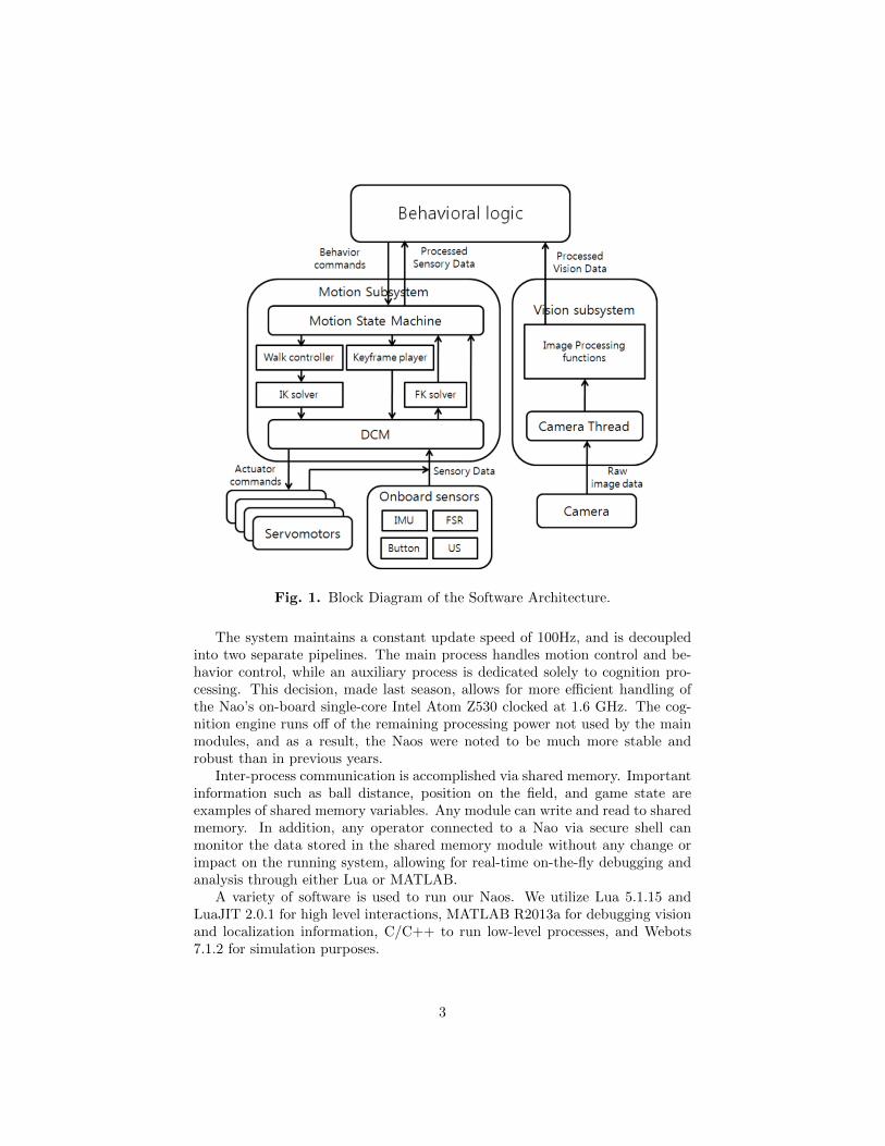
A high-level description of the software architecture for the Naos is shown inFigure 1. The current architecture is an expansion upon the previous yearswork. It uses Lua as a common development platform to interface between allmodules.
Low-level interactions with hardware are implemented using compiled C li-braries in conjunction with the Nao’s on-board hardware controller (NaoQi) orcustom controllers. These in turn, are called via Lua scripts, and allow for con-trol over motor positions, motor stiffnesses, and LED’s. Sensory feedback is alsohandled similarly, allowing users to get data from a variety of sources such asthe Nao’s two on-board cameras, foot weight sensors, the inertial measurementunit (IMU), and the ultrasound microphones.
2
Fig. 1. Block Diagram of the Software Architecture.
The system maintains a constant update speed of 100Hz, and is decoupledinto two separate pipelines. The main process handles motion control and be-havior control, while an auxiliary process is dedicated solely to cognition pro-cessing. This decision, made last season, allows for more efficient handling ofthe Nao’s on-board single-core Intel Atom Z530 clocked at 1.6 GHz. The cog-nition engine runs off of the remaining processing power not used by the mainmodules, and as a result, the Naos were noted to be much more stable androbust than in previous years.
Inter-process communication is accomplished via shared memory. Importantinformation such as ball distance, position on the field, and game state areexamples of shared memory variables. Any module can write and read to sharedmemory. In addition, any operator connected to a Nao via secure shell canmonitor the data stored in the shared memory module without any change orimpact on the running system, allowing for real-time on-the-fly debugging andanalysis through either Lua or MATLAB.
A variety of software is used to run our Naos. We utilize Lua 5.1.15 andLuaJIT 2.0.1 for high level interactions, MATLAB R2013a for debugging visionand localization information, C/C++ to run low-level processes, and Webots7.1.2 for simulation purposes.
3
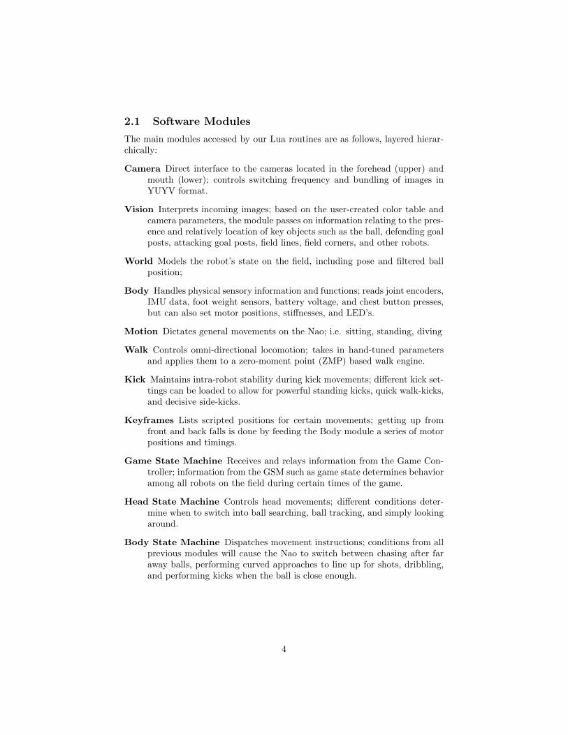
2.1 Software Modules
The main modules accessed by our Lua routines are as follows, layered hierar-chically:
Camera Direct interface to the cameras located in the forehead (upper) andmouth (lower); controls switching frequency and bundling of images inYUYV format.
Vision Interprets incoming images; based on the user-created color table andcamera parameters, the module passes on information relating to the pres-ence and relatively location of key objects such as the ball, defending goalposts, attacking goal posts, field lines, field corners, and other robots.
World Models the robot’s state on the field, including pose and filtered ballposition;
Body Handles physical sensory information and functions; reads joint encoders,IMU data, foot weight sensors, battery voltage, and chest button presses,but can also set motor positions, stiffnesses, and LED’s.
Motion Dictates general movements on the Nao; i.e. sitting, standing, diving
Walk Controls omni-directional locomotion; takes in hand-tuned parametersand applies them to a zero-moment point (ZMP) based walk engine.
Kick Maintains intra-robot stability during kick movements; different kick set-tings can be loaded to allow for powerful standing kicks, quick walk-kicks,and decisive side-kicks.
Keyframes Lists scripted positions for certain movements; getting up fromfront and back falls is done by feeding the Body module a series of motorpositions and timings.
Game State Machine Receives and relays information from the Game Con-troller; information from the GSM such as game state determines behavioramong all robots on the field during certain times of the game.
Head State Machine Controls head movements; different conditions deter-mine when to switch into ball searching, ball tracking, and simply lookingaround.
Body State Machine Dispatches movement instructions; conditions from allprevious modules will cause the Nao to switch between chasing after faraway balls, performing curved approaches to line up for shots, dribbling,and performing kicks when the ball is close enough.
4
3 Vision
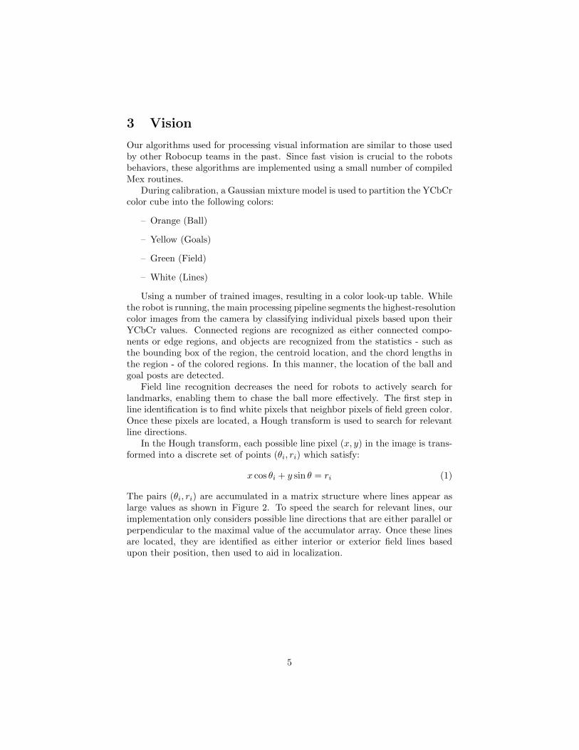
Our algorithms used for processing visual information are similar to those usedby other Robocup teams in the past. Since fast vision is crucial to the robotsbehaviors, these algorithms are implemented using a small number of compiledMex routines.
During calibration, a Gaussian mixture model is used to partition the YCbCrcolor cube into the following colors:
– Orange (Ball)
– Yellow (Goals)
– Green (Field)
– White (Lines)
Using a number of trained images, resulting in a color look-up table. Whilethe robot is running, the main processing pipeline segments the highest-resolutioncolor images from the camera by classifying individual pixels based upon theirYCbCr values. Connected regions are recognized as either connected compo-nents or edge regions, and objects are recognized from the statistics - such asthe bounding box of the region, the centroid location, and the chord lengths inthe region - of the colored regions. In this manner, the location of the ball andgoal posts are detected.
Field line recognition decreases the need for robots to actively search forlandmarks, enabling them to chase the ball more effectively. The first step inline identification is to find white pixels that neighbor pixels of field green color.Once these pixels are located, a Hough transform is used to search for relevantline directions.
In the Hough transform, each possible line pixel (x, y) in the image is trans-formed into a discrete set of points (θi, ri) which satisfy:
x cos θi + y sin θ = ri (1)
The pairs (θi, ri) are accumulated in a matrix structure where lines appear aslarge values as shown in Figure 2. To speed the search for relevant lines, ourimplementation only considers possible line directions that are either parallel orperpendicular to the maximal value of the accumulator array. Once these linesare located, they are identified as either interior or exterior field lines basedupon their position, then used to aid in localization.
5
Fig. 2. Hough transformation for field line detection in images.
3.1 Calibrating and Debugging
3.1.1 Monitoring
To debug the vision code, we developed a tool to receive image packets from anactive robot and display them. To this end, we broadcast YUYV images,as wellas two labeled images. The YUYV images represent what a robot is literallyseeing at any given time, and the labeled images depict what the robot thinksit is seeing at that same time. We programmed a GUI in MATLAB whichreceives these packets, reconstruct them, and then displays them for the userto see. Through the use of this debugging tool, it is possible for us to test andimprove our color look up tables with ease.
Fig. 3. Monitor for Debugging.
3.1.2 Setting Camera Parameters
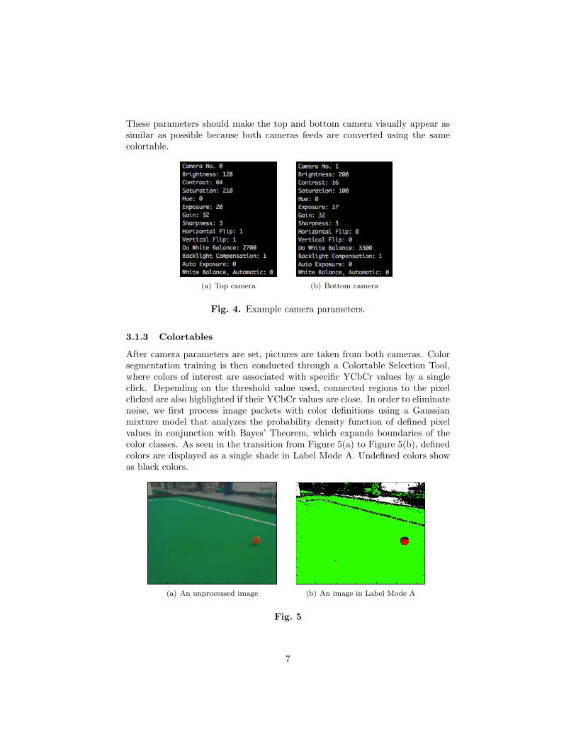
Since vision depends highly on the quality of pictures from the camera, settingcamera parameters (i.e. Exposure, Contrast, and Saturation) properly is crucialto the developing and debugging of vision code. To get better images andchange parameters easily, the camera driver was modified and a Lua script wasdeveloped. Figures 4(a) and 4(b) display a set of camera parameter values.
6
These parameters should make the top and bottom camera visually appear assimilar as possible because both cameras feeds are converted using the samecolortable.
(a) Top camera (b) Bottom camera
Fig. 4. Example camera parameters.
3.1.3 Colortables
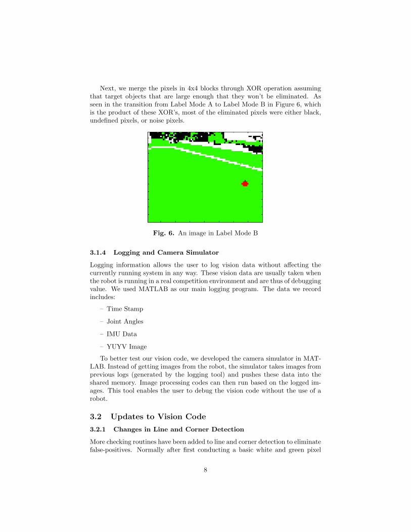
After camera parameters are set, pictures are taken from both cameras. Colorsegmentation training is then conducted through a Colortable Selection Tool,where colors of interest are associated with specific YCbCr values by a singleclick. Depending on the threshold value used, connected regions to the pixelclicked are also highlighted if their YCbCr values are close. In order to eliminatenoise, we first process image packets with color definitions using a Gaussianmixture model that analyzes the probability density function of defined pixelvalues in conjunction with Bayes’ Theorem, which expands boundaries of thecolor classes. As seen in the transition from Figure 5(a) to Figure 5(b), definedcolors are displayed as a single shade in Label Mode A. Undefined colors showas black colors.
(a) An unprocessed image (b) An image in Label Mode A
Fig. 5
7
Next, we merge the pixels in 4x4 blocks through XOR operation assumingthat target objects that are large enough that they won’t be eliminated. Asseen in the transition from Label Mode A to Label Mode B in Figure 6, whichis the product of these XOR’s, most of the eliminated pixels were either black,undefined pixels, or noise pixels.
Fig. 6. An image in Label Mode B
3.1.4 Logging and Camera Simulator
Logging information allows the user to log vision data without affecting thecurrently running system in any way. These vision data are usually taken whenthe robot is running in a real competition environment and are thus of debuggingvalue. We used MATLAB as our main logging program. The data we recordincludes:
– Time Stamp
– Joint Angles
– IMU Data
– YUYV Image
To better test our vision code, we developed the camera simulator in MAT-LAB. Instead of getting images from the robot, the simulator takes images fromprevious logs (generated by the logging tool) and pushes these data into theshared memory. Image processing codes can then run based on the logged im-ages. This tool enables the user to debug the vision code without the use of arobot.
3.2 Updates to Vision Code
3.2.1 Changes in Line and Corner Detection
More checking routines have been added to line and corner detection to eliminatefalse-positives. Normally after first conducting a basic white and green pixel
8
check, white blobs are put through various tests to determine whether theyare lines or corners. As seen in Figure 7, these tests are crucial as there isoften a lot of white noise in the background that would result in false-positives.Line and corner tests include ground checks, cross checks, line overlap checks,length-width ratio thresholds, horizon checks, and an in-field check.
One important addition to our line tests was a distance check. Line detectionfrom far away is useless anyways due to size fluctuation caused by noise and/ornot enough white pixels surviving the transition from Label Mode A to LabelMode B. Lines that appear too close or too far away pose the risk of throwingoff the robot’s localization.
Fig. 7. Only a true white line detected in Label Mode B
In regards to corner detection, a new addition to our tests was the elimina-tion of the center circle by means of location on field. False corners are oftendetected on the surface of the center circle, causing localization to be inaccu-rate. Ultimately, line and corner detection are low-weighted contributions tolocalization that are designed to pick up most lines and corners rather than alllines and corners in order to avoid detecting even a few false lines and corners.
3.2.2 Changes in Spot and Ball Detection
Spot and ball detection code were updated to include successful tests from lineand corner detection. Such changes include the addition of a distance checkand a check for field opposite the part of a ball or spot partially cut off by thecamera at the periphery of its vision. Both changes made the detection of falseballs much more unlikely and did not seem to hinder the detection of true ballswhile in competition.
9
3.2.3 Changes in Goal Detection
The variance in goal distance calculation has always been a crucial source oferror in vision and localization. As a quick fix to the problem with the Naorobot miscalculating its distance away from goal posts by a uniform numberfrom any point on a field, we implemented a goal distance factor. This factormultiplies the distance from the goal that the localization code uses. Beforeevery match, we simply needed to update the factor after placing the robot atdifferent distances from the goal posts.
4 Localization
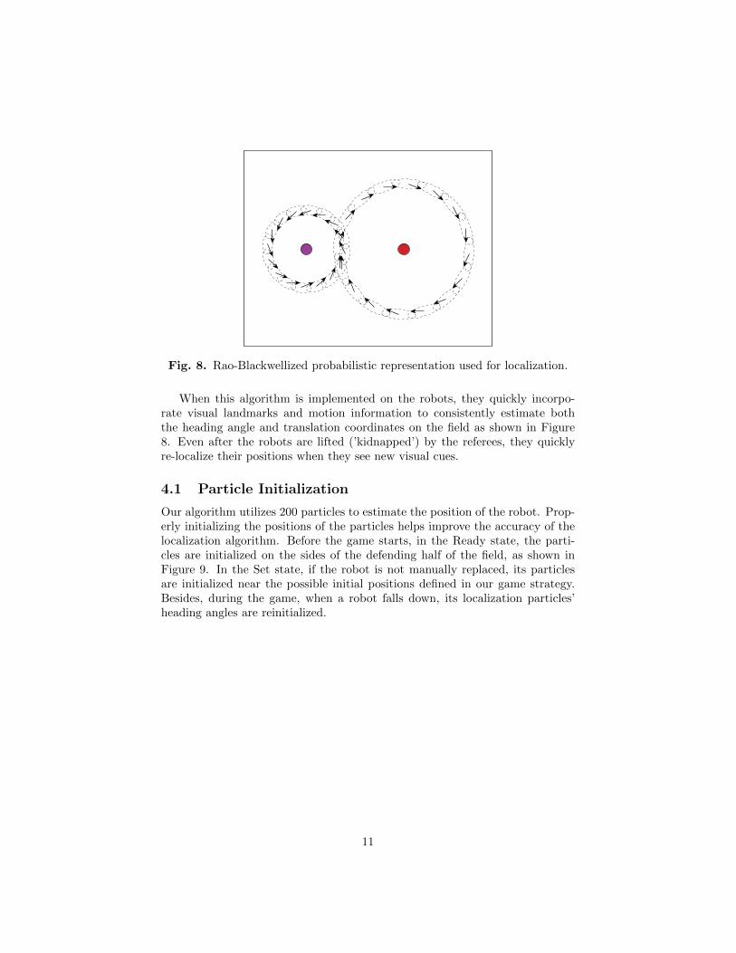
The problem of knowing the location of robots on the field is handled by aprobabilistic model incorporating information from visual landmarks such asgoals and lines, as well as odometry information from the effectors. Recently,probabilistic models for pose estimation such as extended Kalman filters, grid-based Markov models, and Monte Carlo particle filters have been successfullyimplemented. Unfortunately, complex probabilistic models can be difficult toimplement in real-time due to a lack of processing power on board the robots.We address this issue with a pose estimation algorithm that incorporates a hy-brid Rao-Blackwellized representation that reduces computational time, whilestill providing a high level of accuracy. Our algorithm models the pose uncer-tainty as a distribution over a discrete set of heading angles and continuoustranslational coordinates. The distribution over poses (x, y, θ), where (x, y) arethe two-dimensional translational coordinates of the robot on the field, and θ isthe heading angle, is first generically decomposed into the product:
P (x, y, θ) = P (θ)P (x, y|θ) =∑i
P (θi)P (x, y, |θi) (2)
We model the distribution P (θ) as a discrete set of weighted samples {θi},and the conditional likelihood P (x, y|θ) as simple two-dimensional Gaussian.This approach has the advantage of combining discrete Markov updates for theheading angle with Kalman filter updates for translational degrees of freedom.
10
Fig. 8. Rao-Blackwellized probabilistic representation used for localization.
When this algorithm is implemented on the robots, they quickly incorpo-rate visual landmarks and motion information to consistently estimate boththe heading angle and translation coordinates on the field as shown in Figure8. Even after the robots are lifted (’kidnapped’) by the referees, they quicklyre-localize their positions when they see new visual cues.
4.1 Particle Initialization
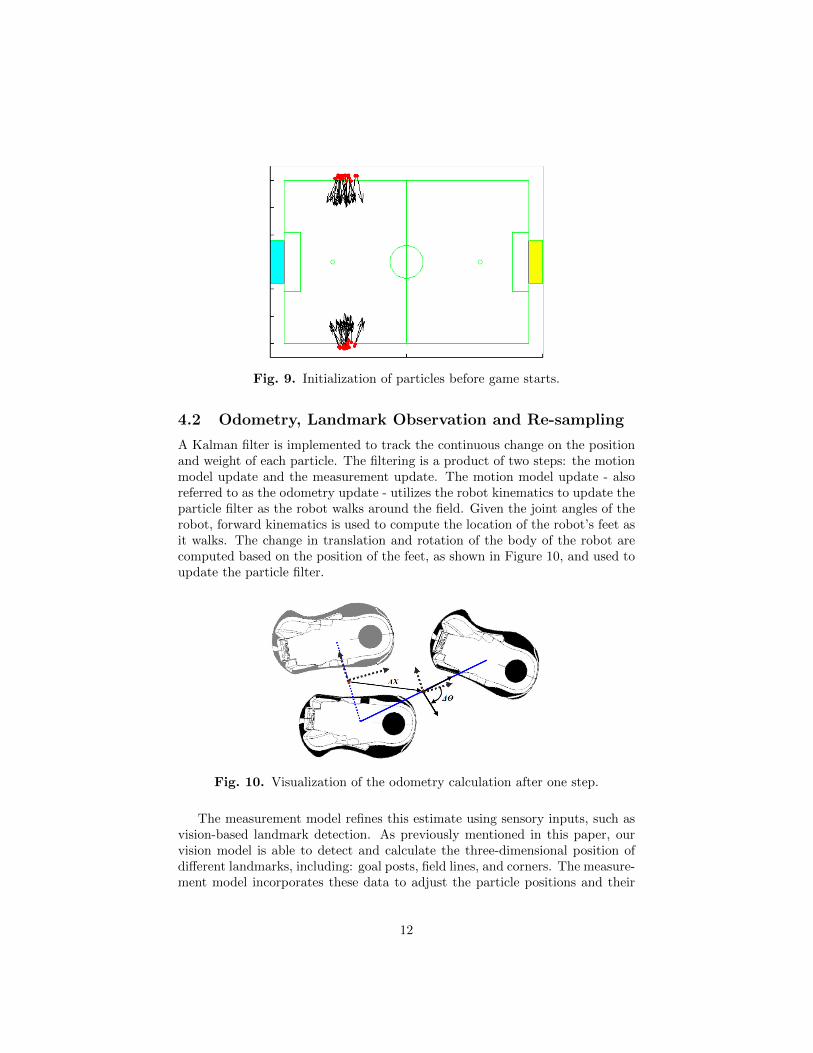
Our algorithm utilizes 200 particles to estimate the position of the robot. Prop-erly initializing the positions of the particles helps improve the accuracy of thelocalization algorithm. Before the game starts, in the Ready state, the parti-cles are initialized on the sides of the defending half of the field, as shown inFigure 9. In the Set state, if the robot is not manually replaced, its particlesare initialized near the possible initial positions defined in our game strategy.Besides, during the game, when a robot falls down, its localization particles’heading angles are reinitialized.
11
Fig. 9. Initialization of particles before game starts.
4.2 Odometry, Landmark Observation and Re-sampling
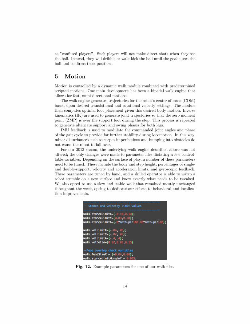
A Kalman filter is implemented to track the continuous change on the positionand weight of each particle. The filtering is a product of two steps: the motionmodel update and the measurement update. The motion model update - alsoreferred to as the odometry update - utilizes the robot kinematics to update theparticle filter as the robot walks around the field. Given the joint angles of therobot, forward kinematics is used to compute the location of the robot’s feet asit walks. The change in translation and rotation of the body of the robot arecomputed based on the position of the feet, as shown in Figure 10, and used toupdate the particle filter.
Fig. 10. Visualization of the odometry calculation after one step.
The measurement model refines this estimate using sensory inputs, such asvision-based landmark detection. As previously mentioned in this paper, ourvision model is able to detect and calculate the three-dimensional position ofdifferent landmarks, including: goal posts, field lines, and corners. The measure-ment model incorporates these data to adjust the particle positions and their
12
weights in the filter. Due to the difference in reliability of different landmarkdetections, we incorporate different types of observed landmark positions differ-ently. For instance, while goal post detection is used to correct both the positionand heading angles, corner and line detections are mainly used to correct theheading angles since the variance in their position calculation is relatively large.
Our algorithm re-samples all of the particles every 0.1 seconds. We use thestratification method to redraw all of the particles so that the ones with higherweight will stay. Figure 11 illustrate the result of our algorithm. While therobot is moving on field, the particles are drawn in our debugging tool.
Fig. 11. The robot takes in and weighs landmarks to establish an accurateestimation of its position on the field.
4.3 Error Correction
One great challenge in the Standard Platform League is the symmetric field.Under ideal circumstances where the robot’s starting position is known, thebasic particle filter approach alone is enough to keep track of the correct robotpose. However, noise in the motion model, inevitable false positive detections oflandmarks, and falling down, will all eventually cause the robot to converge ona pose that is symmetrically opposite the true location. This year, the problemis further complicated by the increase in the size of competition fields, whichresults in higher variance in vision detection. To address this problem, we usethe team correcting mechanism based on goalie ball information.
For most of the cases, the goalie stays in the penalty box, and it stays closeto the defending goal posts. Therefore, among the five players on the field, thegoalie is most confident about its location, as well as the detected ball position.During the game, if a player robot and the goalie see the ball simultaneouslybut they believe the ball is on different sides of the field, it is very likely thatthe player robot’s localization is flipped. Under such circumstances, its particleswill be flipped according to the center of the field.
Moreover, since the robots are very likely to generate localization error whenthey fall over near the center of the field, we label robots that fall near the center
13
as ”confused players”. Such players will not make direct shots when they seethe ball. Instead, they will dribble or walk-kick the ball until the goalie sees theball and confirms their positions.
5 Motion
Motion is controlled by a dynamic walk module combined with predeterminedscripted motions. One main development has been a bipedal walk engine thatallows for fast, omni-directional motions.
The walk engine generates trajectories for the robot’s center of mass (COM)based upon desired translational and rotational velocity settings. The modulethen computes optimal foot placement given this desired body motion. Inversekinematics (IK) are used to generate joint trajectories so that the zero momentpoint (ZMP) is over the support foot during the step. This process is repeatedto generate alternate support and swing phases for both legs.
IMU feedback is used to modulate the commanded joint angles and phaseof the gait cycle to provide for further stability during locomotion. In this way,minor disturbances such as carpet imperfections and bumping into obstacles donot cause the robot to fall over.
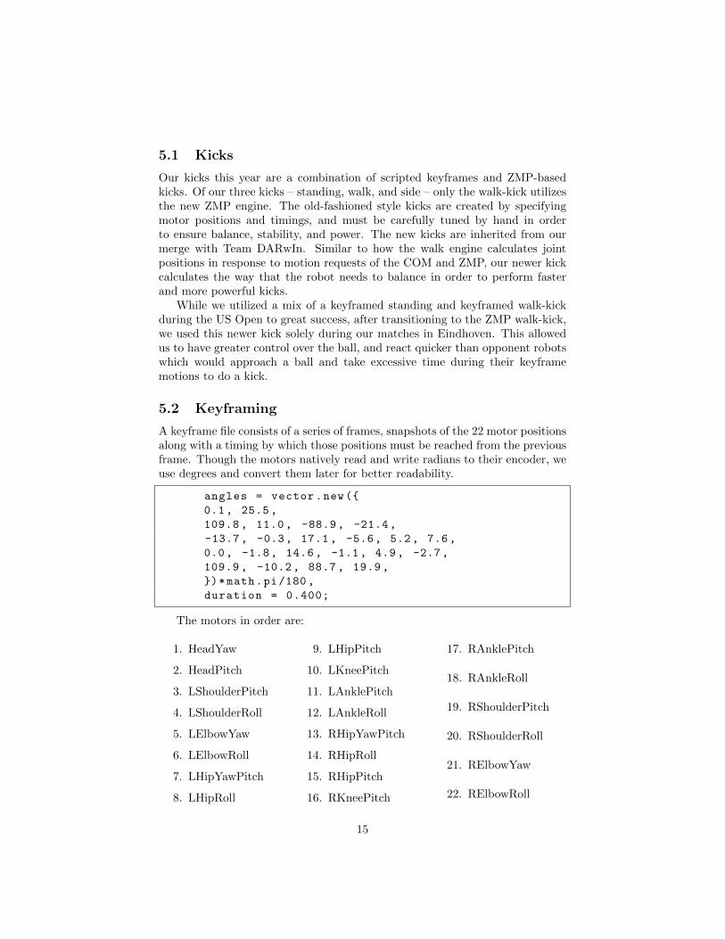
For our 2013 season, the underlying walk engine described above was notaltered; the only changes were made to parameter files dictating a few control-lable variables. Depending on the surface of play, a number of these parametersneed to be tuned. These include the body and step height, percentages of single-and double-support, velocity and acceleration limits, and gyroscopic feedback.These parameters are tuned by hand, and a skilled operator is able to watch arobot stumble on a new surface and know exactly what needs to be tweaked.We also opted to use a slow and stable walk that remained mostly unchangedthroughout the week, opting to dedicate our efforts to behavioral and localiza-tion improvements.
Fig. 12. Example parameters for one of our walk files.
14
5.1 Kicks
Our kicks this year are a combination of scripted keyframes and ZMP-basedkicks. Of our three kicks – standing, walk, and side – only the walk-kick utilizesthe new ZMP engine. The old-fashioned style kicks are created by specifyingmotor positions and timings, and must be carefully tuned by hand in orderto ensure balance, stability, and power. The new kicks are inherited from ourmerge with Team DARwIn. Similar to how the walk engine calculates jointpositions in response to motion requests of the COM and ZMP, our newer kickcalculates the way that the robot needs to balance in order to perform fasterand more powerful kicks.
While we utilized a mix of a keyframed standing and keyframed walk-kickduring the US Open to great success, after transitioning to the ZMP walk-kick,we used this newer kick solely during our matches in Eindhoven. This allowedus to have greater control over the ball, and react quicker than opponent robotswhich would approach a ball and take excessive time during their keyframemotions to do a kick.
5.2 Keyframing
A keyframe file consists of a series of frames, snapshots of the 22 motor positionsalong with a timing by which those positions must be reached from the previousframe. Though the motors natively read and write radians to their encoder, weuse degrees and convert them later for better readability.
angles = vector.new({
0.1, 25.5,
109.8, 11.0, -88.9, -21.4,
-13.7, -0.3, 17.1, -5.6, 5.2, 7.6,
0.0, -1.8, 14.6, -1.1, 4.9, -2.7,
109.9, -10.2, 88.7, 19.9,
})*math.pi/180,
duration = 0.400;
The motors in order are:
1. HeadYaw
2. HeadPitch
3. LShoulderPitch
4. LShoulderRoll
5. LElbowYaw
6. LElbowRoll
7. LHipYawPitch
8. LHipRoll
9. LHipPitch
10. LKneePitch
11. LAnklePitch
12. LAnkleRoll
13. RHipYawPitch
14. RHipRoll
15. RHipPitch
16. RKneePitch
17. RAnklePitch
18. RAnkleRoll
19. RShoulderPitch
20. RShoulderRoll
21. RElbowYaw
22. RElbowRoll
15
We utilize keyframed motions for two types of kicks, and also for our get-upmotions. Like our walk, keyframes are hand-tuned based upon experimentation.To prolong the life of our robots, we do most of the heavy keyframe testing inWebots and then port it to the robots and perform final checks to verify fullfunctionality.
6 Behavior
Finite state machines (FSMs) dictate the behaviors on our Naos and allow themto adapt to constantly changing conditions on the field. Updated at a speedof 100Hz, FSM’s are analogous to flow charts. Our implementation of an FSMconsists of a file that defines the transitions (BodyFSM.lua and HeadFSM.lua forthe body and head, respectively) and a series of larger files that define specificstates (i.e. bodyPosition.lua or headSweep.lua). A specific state consists ofthree main functions entry, update, and exit.
As their names suggest, the entry and exit functions specify actions thatneed to be taken when a robot first enters a state or when it finally completesa state. An example of a typical entry action is print( NAME..entry), whichsends a simple print statement to the main feed and tells an operator what statea robot is currently in. Exit statements tend to be empty and are simply thereto facilitate state machine functionality, but occasionally contain an action suchas telling the Motion module to command a stance when leaving bodyIdle.
After entering and before exiting, the Nao will constantly cycle through thebody of a state (the update function), querying the environment until certainconditions are met. During bodySearch, for example, the robot will rotate inplace until either a) the ball is spotted and causes a transition to bodyPositionto determine how far away the ball is; b) it times out after a certain amount oftime has been spent updating, and will transition to bodyGoToCenter to movethe robot towards the center of the field in hopes of finding a ball.
Non-goalie behaviors are described here because they apply to a majority ofthe robots on the field (4 out of 5). The goalie will utilize the same transitionfile as a regular player, but instead uses a series of states unique only to thegoalie.
16
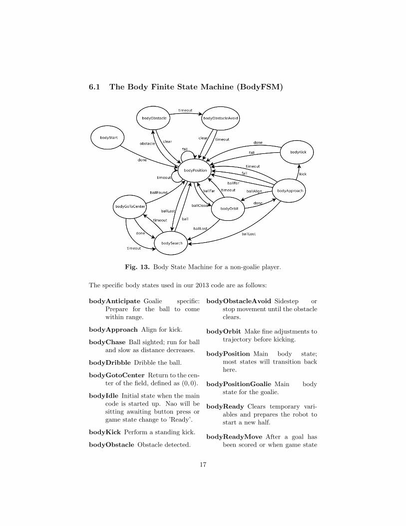
6.1 The Body Finite State Machine (BodyFSM)
Fig. 13. Body State Machine for a non-goalie player.
The specific body states used in our 2013 code are as follows:
bodyAnticipate Goalie specific:Prepare for the ball to comewithin range.
bodyApproach Align for kick.
bodyChase Ball sighted; run for balland slow as distance decreases.
bodyDribble Dribble the ball.
bodyGotoCenter Return to the cen-ter of the field, defined as (0, 0).
bodyIdle Initial state when the maincode is started up. Nao will besitting awaiting button press orgame state change to ’Ready’.
bodyKick Perform a standing kick.
bodyObstacle Obstacle detected.
bodyObstacleAvoid Sidestep orstop movement until the obstacleclears.
bodyOrbit Make fine adjustments totrajectory before kicking.
bodyPosition Main body state;most states will transition backhere.
bodyPositionGoalie Main bodystate for the goalie.
bodyReady Clears temporary vari-ables and prepares the robot tostart a new half.
bodyReadyMove After a goal hasbeen scored or when game state
17
is ’Ready’, returns the robot toits initial position on the field.
bodySearch Revolve and search forthe ball.
bodyStart Initial state when gamegoes to ’Playing’; handles kickoff.
bodyStop Stops the robot com-
pletely.
bodyWalkKick Perform a kick whilein motion.
bodyUnpenalized Commands theNao to stand back up and walkinto the field after being unpe-nalized.
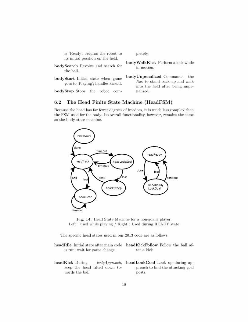
6.2 The Head Finite State Machine (HeadFSM)
Because the head has far fewer degrees of freedom, it is much less complex thanthe FSM used for the body. Its overall functionality, however, remains the sameas the body state machine.
Fig. 14. Head State Machine for a non-goalie player.Left : used while playing / Right : Used during READY state
The specific head states used in our 2013 code are as follows:
headIdle Initial state after main codeis run; wait for game change.
headKick During bodyApproach,keep the head tilted down to-wards the ball.
headKickFollow Follow the ball af-ter a kick.
headLookGoal Look up during ap-proach to find the attacking goalposts.
18
headReady Localize duringBodyReadyMove by finding lines.
headReadyLookGoal When in theinitial position, look towards theattacking goal posts to localize.
headScan Look around for the ball.
headStart Initial state after thegame state changes to ’Playing’.
headSweep Perform a generalsearch, with a priority on findinggoal posts.
headTrack Track the ball, moving orstationary.
headTrackGoalie Goalie-specific:Track the approaching ball.
6.3 Changing Behaviors
Adding new states is fairly simple to do. First, a declaration of a new state,followed by its relevant transitions, must be set in the head file (BodyFSM.luaor HeadFSM.lua).
Then the new state file must be placed in the same folder as the head file, andmust contain an entry, update, and exit function.
function entry ()
#actions
..
function update ()
#actions
..
function exit()
#actions
In this way, new behaviors can quickly be added or existing ones modified asrequired.
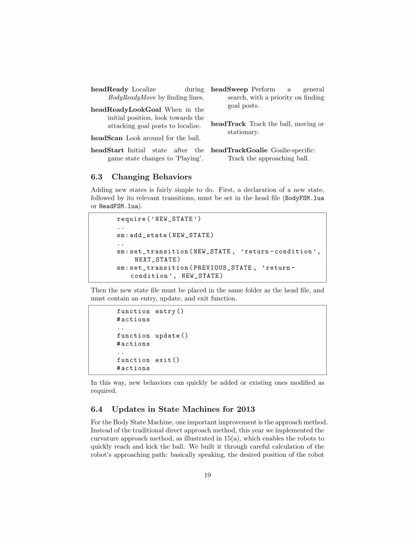
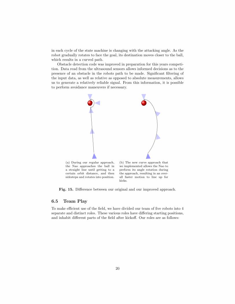
6.4 Updates in State Machines for 2013
For the Body State Machine, one important improvement is the approach method.Instead of the traditional direct approach method, this year we implemented thecurvature approach method, as illustrated in 15(a), which enables the robots toquickly reach and kick the ball. We built it through careful calculation of therobot’s approaching path: basically speaking, the desired position of the robot
19
in each cycle of the state machine is changing with the attacking angle. As therobot gradually rotates to face the goal, its destination moves closer to the ball,which results in a curved path.
Obstacle detection code was improved in preparation for this years competi-tion. Data read from the ultrasound sensors allows informed decisions as to thepresence of an obstacle in the robots path to be made. Significant filtering ofthe input data, as well as relative as opposed to absolute measurements, allowsus to generate a relatively reliable signal. From this information, it is possibleto perform avoidance maneuvers if necessary.
(a) During our regular approach,the Nao approaches the ball ina straight line until getting to acertain orbit distance, and thensidesteps and rotates into position.
(b) The new curve approach thatwe implemented allows the Nao toperform its angle rotation duringthe approach, resulting in an over-all faster motion to line up forkicks.
Fig. 15. Difference between our original and our improved approach.
6.5 Team Play
To make efficient use of the field, we have divided our team of five robots into 4separate and distinct roles. These various roles have differing starting positions,and inhabit different parts of the field after kickoff. Our roles are as follows:
20
Goalie 1 Stays in and around the defensive goal to clearthe ball when it comes close.
Attacker 2 Goes directly towards the ball and kicks.Supporter 3 Follows the attacking robot up-field, but stays
at a respectable distance away—usually aboutmidfield.
Defender 4 The defending robot positions itself betweenthe ball and defensive goal area.
Defender Two 5 Performs double duty with the first defender,but has a different initial position.
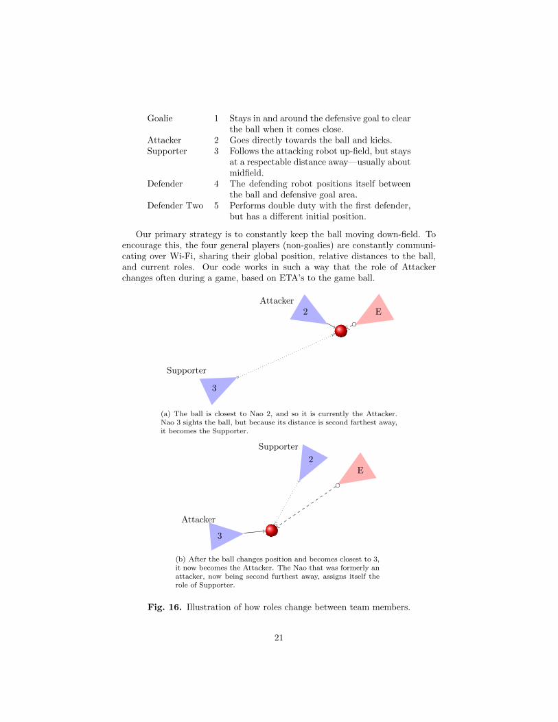
Our primary strategy is to constantly keep the ball moving down-field. Toencourage this, the four general players (non-goalies) are constantly communi-cating over Wi-Fi, sharing their global position, relative distances to the ball,and current roles. Our code works in such a way that the role of Attackerchanges often during a game, based on ETA’s to the game ball.
3
Supporter
2Attacker
E
(a) The ball is closest to Nao 2, and so it is currently the Attacker.Nao 3 sights the ball, but because its distance is second farthest away,it becomes the Supporter.
3
Attacker
2
Supporter
E
(b) After the ball changes position and becomes closest to 3,it now becomes the Attacker. The Nao that was formerly anattacker, now being second furthest away, assigns itself therole of Supporter.
Fig. 16. Illustration of how roles change between team members.
21
Take for example, this situation. Following kickoff, Nao #2, initially assignedas the Attacker, gets the ball into the opponent half. An opponent defendersteals the ball away, and with a powerful kick, sends it back into our half. IfDefender Two (Nao #5) finds the ball stopped closest to him, he will inform theteam that he is switching into the Attacker role. The other three general playerswill then check how far they are to the ball, and assign themselves roles in orderof ascending distance to the ball. The next closest robot, regardless of numberand initial role, would become the new Supporter, while the two furthest awaywould become Defenders One and Two.
In this way, the team can reach and move the ball much quicker and withmore efficiency by behaving as a dynamic unit.
7 Summary
While the UPennalizers broke their annual tradition of making it to the quarter-final matches every year, the team has continued to keep pace with the rest ofthe league. With a new batch of undergraduates ready to pass on their knowl-edge to new team members in the fall, the UPennalizers’ future looks as brightas ever.
Our 2013 demo code has been released on our website under the GNU publiclicense, and we hope that it will be of use to future teams.