capacity in the symmetrical anchor plate’s length or diameter when placed in sand in loose packing.
For symmetrical anchor plates in dense packing, Fig. 5 illustrates symmetrical rectangular anchor
plates’ uplift response based on length. The increase in uplift capacity with the symmetrical anchor
plate’s size, regardless of packing conditions, is due to the increased lateral stresses acting on the
symmetrical anchor plates with the depth and increasing contact area between the symmetrical anchor
plates and the embedment media. This can be understood from the formula of the uplift response,
AH , where symmetrical anchor size is one of the parameters. Therefore, an increase of the
symmetrical anchor plate’s size would increase the uplift capacity, as given by Balla’s formula (1961),
AH . From Figs. 4 and 5, a geometric increase of uplift capacity in square and rectangular plates in
both loose and dense packing is evident.
Fig. 3. Variation of uplift capacity Q with symmetrical anchor Fig. 4. Variation of uplift capacity Q with symmetrical anchor plate size D for circular anchor plate at L/D=4 in loose plate size D for square anchor plate at L/D=4 in loose and dense sand. and dense sand.
Hamed Niroumand and Khairul Anuar Kassim / China Ocean Eng., 28(1), 2014, 115 − 126 120
As seen from Fig. 6, symmetrical anchor plates in the maximum embedment ratio, L/D=4, have
larger uplift capacities than symmetrical anchor plates in the minimum embedment ratio such as
L/D=1. The increases of breakout factor for symmetrical anchor plates embedded in loose sand
compared with dense sand are illustrated in Fig. 6. These increases are, however, non-linear for loose
and dense packing in sand.
Fig. 5. Variation of uplift capacity Q with symmetrical anchor Fig. 6. Variation of breakout factor Nq with embedment ratio plate size D for rectangular anchor plate at L/D=3 in L/D for symmetrical anchor plates in both loose and loose and dense sand. dense sand packing.
The discussion of uplift capacity of symmetrical anchor plates in reinforced sand involves a
separate analysis of the parameters of number of GFR layers, GFR layer length, GFR layer proximity
to the anchor and vertical spacing of the GFR layers. GFR as one type of geosynthetics was used in
this study. Typical physical and technical properties were obtained from the manufacturer’s data sheet
and are given in Table 1. This is to enable an impartial and focused review of the effect of each
parameter on the symmetrical anchor plate during the uplift test. One of the areas that need to be
considered is the effect of reinforced sand on symmetrical anchor plates. The uplift responses of the
symmetrical anchor plates with or without soil reinforcement (Pu and Po, respectively) were obtained
from the uplift load. Improvement of the symmetrical anchor plate’s capacity due to soil reinforcement
is represented using a non-dimensional factor, called the symmetrical anchor plate capacity ratio (El
Sawwaf, 2007), to assist the comparison of the test results. This factor (ACR) is defined as the ratio of
the symmetrical anchor plate’s ultimate capacity with soil reinforcement, Pu-reinforced, to the ultimate
capacity of symmetrical anchor plate in tests without soil reinforcement, Po. These results are
discussed in the following sections. In this study, GFR length (B) was not kept constant and the
number of GFR layers varied for researches. Figs. 7 and 8 illustrate the performance of the GFR at
various x/D.
With reference to Figs. 9 and 10, tests were performed to study the effect of reinforced sand with
various numbers of GFR inclusions on the behavior of the symmetrical anchor plate located in the
loose and dense sand and at embedment depths of 14. In reinforced tests, GFR layers were placed at
equal vertical spacings of 0.5B, 0.75B, and 1B with the first layer placed on the plate at 0 and 0.5B.
The variations of the symmetrical anchor plate’s capacities with u/D for a number of various GFR
layers are plotted in Figs. 9 and 10. The figures clearly show that the anchor plate’s behavior is largely
improved with soil reinforcement.
Hamed Niroumand and Khairul Anuar Kassim / China Ocean Eng., 28(1), 2014, 115 − 126 121
Fig. 7. Variation of ACR with B'/B of GFR layer at x/D=0. Fig. 8. Variation of ACR with B'/B of GFR layer at x/D=0.5.
Fig. 9. Variation of ACR with a number of GFR layers at Fig. 10. Variation of ACR with amount of GFR layers at
x/D=0 and u/D=0.5. x/D=0.5 and u/D=0.5.
Also, it can be seen that the inclusion of GFR layers has a much better result than that of non-
reinforced layers. In fact, the inclusion of multi layers of GFR resting directly on the top of the plate
enhances reinforcement to approximately the same extent as the inclusion of a single layer. Therefore,
it can be concluded that, in terms of symmetrical anchor plate’s capacity, using one GFR layer is
equivalent to, but more economical than, reinforcing the soil itself with several layers.
8. Discussion
This part presents a comparison of theoretical and experimental values for the experimental and
numerical programs conducted. Figs. 1114 illustrate a comparison of theoretical and experimental
values as forwarded by various researchers such as Balla (1961), Meyerhof and Adams (1968), Vesic
(1971), Rowe and Davis (1982), and Murray and Geddes (1987). The difference among these
theoretical predictions lies in the value of the breakout factor in uplift. Balla (1961), Meyerhof and
Adams (1968), Vesic (1971), Rowe and Davis (1982), and Murray and Geddes (1987) proposed
theoretical values based on the curved failure model determined by the method of analytical and
experimental evaluation in non-reinforced sand.
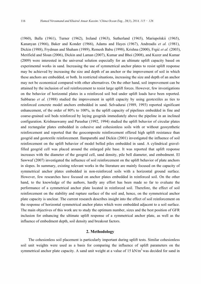
Figs. 11 and 12 illustrate comparisons of theoretical breakout factor values and current results
based on experimental and numerical analysis. The overall trend indicates that, for the series of tests
and models conducted, experimental and numerical values are in close agreement and similar to values
of Balla (1961) for circular plates, Vesic (1971) for square plates and Meyerhof and Adams (1968) for
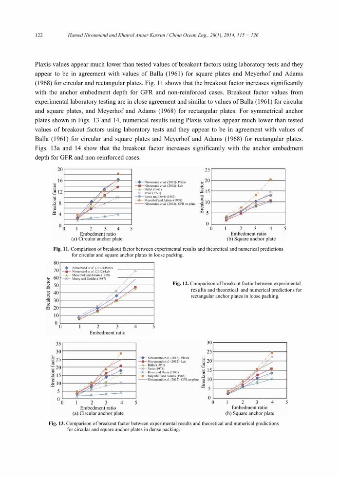
rectangular plates. For symmetrical anchor plates shown in Figs. 13 and 14, numerical results using
Hamed Niroumand and Khairul Anuar Kassim / China Ocean Eng., 28(1), 2014, 115 − 126 122
Plaxis values appear much lower than tested values of breakout factors using laboratory tests and they
appear to be in agreement with values of Balla (1961) for square plates and Meyerhof and Adams
(1968) for circular and rectangular plates. Fig. 11 shows that the breakout factor increases significantly
with the anchor embedment depth for GFR and non-reinforced cases. Breakout factor values from
experimental laboratory testing are in close agreement and similar to values of Balla (1961) for circular
and square plates, and Meyerhof and Adams (1968) for rectangular plates. For symmetrical anchor
plates shown in Figs. 13 and 14, numerical results using Plaxis values appear much lower than tested
values of breakout factors using laboratory tests and they appear to be in agreement with values of
Balla (1961) for circular and square plates and Meyerhof and Adams (1968) for rectangular plates.
Figs. 13a and 14 show that the breakout factor increases significantly with the anchor embedment
depth for GFR and non-reinforced cases.
Fig. 11. Comparison of breakout factor between experimental results and theoretical and numerical predictions
for circular and square anchor plates in loose packing.
Fig. 12. Comparison of breakout factor between experimental results and theoretical and numerical predictions for rectangular anchor plates in loose packing.
Fig. 13. Comparison of breakout factor between experimental results and theoretical and numerical predictions
for circular and square anchor plates in dense packing.
Hamed Niroumand and Khairul Anuar Kassim / China Ocean Eng., 28(1), 2014, 115 − 126 123
Fig. 14. Comparison of breakout factor between experimental results and theoretical and numerical predictions for rectangular anchor plates in dense packing.
9. Empirical Relationship for Reinforced Sand by GFR
Based on the results, the variations of non-dimensional uplift responses with embedment ratio are
plotted. The tests are based on loose and dense conditions to derive the behavior of symmetrical anchor
plates (such as square, circular and rectangular plates) in sand using GFR. Tests in loose sand
conditions consist of three parts. The first part employs square plates with side lengths of 50 mm, 75
mm and 100 mm with a number of various GFR layers and various x/D, B' and u/D. While the second
part employs circular plates with various diameters of 50 mm, 75 mm and 100 mm with a number of
various GFR layers and various x/D, B' and u/D. The third part employs rectangular plates with various
diameters of 200 mm and 300 mm with a various number of GFR layers and various x/D, B' and u/D.
Similar tests were made for symmetrical anchor plates in dense conditions.
The empirical relationship for symmetrical square and circular anchor plates of length and
diameter, respectively, of 50 mm, 75 mm and 100 mm and rectangular plates of 200 mm and 300 mm
in loose sand conditions using GFR were developed by combining both non-dimensional uplift
responses to obtain average values. These methods were also adopted for dense conditions. The
relationship between various parameters was plotted for symmetrical anchor plates. The empirical
relationship was developed from test results. A linear regression was employed to obtain a linear
relationship of all data included. In square plates, this enables the following empirical relationship to
be derived:
q 1.98 3 / 0.56 /N L D B D . (2)
For dense sand conditions, similar methods used with loose sand were adopted. Thus the
empirical relationship for square anchor plates in dense sand condition can be expressed as:
6.57 3.45 / 0.49 /q
N L D B D , (3)
where L/D and number of GFR layers (N) give a linear equation by means of linear regression with a
coefficient of regression. As the confidence level has been set at 95% in the analysis, the p-value of
significant variables should be smaller than 0.05. According to the analysis, “embedment ratio” and
“ratio of geogrid width to plate width” have significant impacts on the overall service quality. The
impact of “embedment ratio” is positive and the impact of “ratio of geogrid width to plate width” is
negative. In circular plates, this enables the following empirical relationship to be derived as:
q 2.29 2.85 / 0.52 /N L D B D . (4)
Hamed Niroumand and Khairul Anuar Kassim / China Ocean Eng., 28(1), 2014, 115 − 126 124
For the dense sand conditions, similar methods used with loose sand were adopted. Thus
empirical relationships for square anchor plates in dense sand conditions give:
q 6.91 3.30 / 0.45 /N L D B D . (5)
The embedment ratio L/D and number of GFR layers N give a linear equation by means of a
linear regression with a coefficient of regression. As the confidence level has been set at 95% in the
analysis, the p-value of significant variables should be smaller than 0.05. The “embedment ratio” and
“ratio of geogrid width to plate width” have significant impacts on the overall service quality. The
impact of “embedment ratio” is positive and the impact of “ratio of geogrid width to plate width” is
negative. Eqs. (2)–(5) are valid for symmetrical anchor plates in loose and dense sand conditions with
a restriction of / 4L D .
10. Conclusions
Parametric research was conducted to obtain the knowledge on symmetrical anchor plates in loose
and dense soil conditions, such as GFR reinforcement and non-reinforced reinforcement and to
determine the behavior of the symmetrical anchor plates during uplift. Although it is not dedicated to
any specific practical conditions in engineering practice, it is useful to study the various effecting
factors that influence the symmetrical anchor plate’s capacity when subjected to uplift forces. An
analysis of the effect of various parameters has gained a deeper understanding of the behavior of
symmetrical anchor plates in reinforced sand when subjected to uplift loads. The failure shape for
symmetrical anchor plates with embedment ratio / 4L D is cylindrical despite variations in size,
density and reinforcement materials in reinforced sand when subjected to uplift loads. The size and
depth of the anchor plate are important parameters to be taken into consideration when selecting an
appropriate depth to achieve the most economical uplift design. It would therefore be more economical
and rational to increase the uplift capacity of symmetrical anchor plates by simply increasing the
symmetrical anchor plate’s depth, which helps to boost uplift capacity significantly, than by increasing
the symmetrical anchor plate’s size in order to increase the contact area with sand. Selection of the
symmetrical anchor plate’s shape must also be carefully considered to achieve an economical anchor
plate uplift design. Rectangular anchor plates provided a higher uplift response compared with square
or circular anchor plates. A deeply embedded symmetrical rectangular anchor plate proved
substantially more resistant to uplift forces than a symmetrical square or circular anchor plate, due to
the geometric progression in capacity with increase in symmetrical anchor plate’s depth. It is also
important to note that soil packing was found to be the most influential parameter in increasing uplift
capacity. Adequate compaction of soils around the symmetrical anchor plates is an important factor, as
indicated by the tests conducted on soils with relative density. The number and vertical spacing of
GFR layers is an important design factor of symmetrical anchor plates. In fact, the inclusion of multi
layers of GFR resting directly on the top of the plate provides approximately the same effect as the
inclusion of a single layer. However, if multiple layers of GFR reinforcement are required for a
particular design, then the optimum vertical spacing between layers is 0.5B. The outfitted tension trend
in the reinforcement allows the GFR to resist the formed horizontal shear stresses built up in the sand
Hamed Niroumand and Khairul Anuar Kassim / China Ocean Eng., 28(1), 2014, 115 − 126 125
mass inside the loaded zone and move them to stable layers of loose and dense sand leading to a
broader and deeper failure zone. Based on this result, sand GFR interaction not only results in an
increase in the uplift force due to the developed longer failure surface, but also results in an expansion
of the contact zone between the soil and laboratory box. From the detailed analysis given beforehand,
findings of the parametric study can be summarized. Based on the experimental and numerical studies
carried out on symmetrical anchor plates (such as square, circular and rectangular anchor plates) that
were embedded adjacent to an experimental box with two sand densities with or without GFR
reinforcement, the following conclusions can be drawn:
(1) Inclusion of GFR reinforcement in a laboratory test chamber significantly increases the
ultimate uplift resistance of a symmetrical anchor plate embedded in sand.
(2) In cases where design requirements necessitate large uplift resistance, soil reinforcement can
be considered as an economical solution and can be used to obtain the designed symmetrical anchor
plate capacity instead of increasing the embedment depth or anchor size.
(3) In terms of anchor capacity, inclusion of multi layers of GFR over the anchor plate is more
cost effective than sand reinforcement using a single layer.
(4) In terms of symmetrical anchor capacity, the inclusion of multi layers of GFR over the anchor
plate is more effective than soil reinforcement using one layer. In terms of reinforced conditions on
symmetrical anchor plates using multi layers of GFR, the optimal space between GFR layers is 0.5B.
(5) Increased soil density and embedment depth result in greater uplift capacity.
(6) Inclusion of GFR reinforcement in a laboratory chamber significantly increases the uplift force
by developing a longer failure surface, but also results in extending the contact zone between the soil
and laboratory box.
References
Adams, J. I. and Hayes, D. C., 1967. The uplift capacity of shallow foundations, Ontario Hydro-Research
Quarterly.
Andreadis, A., Harvey, R. C. and Burley, E., 1981. Embedded anchor response to uplift loading, J. Geotech. Eng.
Div., ASCE, 107(1): 59–78.
Baker, W. H. and Konder, R. L., 1966. Pullout load capacity of a circular earth anchor buried in sand, Highway
Res. Rec. 108, 1–10.
Balla, A., 1961. The resistance of breaking-out of mushroom foundations for pylons, Proceedings of the 5th
International Conference on Soil Mechanics and Foundation Engineering, Paris, Vol. 1, 569–576.
Bringkgreve, R. and Vermeer, P. 1998. PLAXISFinite Element Code for Soil and Rock Analysis, Version 7,
Plaxis BV, The Netherlands.
Dickin, E. A. and Laman, M., 2007. Uplift response of strip anchors in cohesionless soil, Adv. Eng. Softw., 38(8–
9): 618–625.
Dickin, E. A., 1988. Uplift behavior of horizontal anchor plates in sand, J. Geotech. Eng. Div., ASCE, 114(11):
1300–1317.
El Sawwaf, M. A., 2007. Uplift behavior of horizontal anchor plates buried in geosynthetic reinforced slopes,
Geotech. Test. J., 30(5): 418426.
Hamed Niroumand and Khairul Anuar Kassim / China Ocean Eng., 28(1), 2014, 115 − 126 126
Frgić, L., Marović, P. and Tor, K., 2003. Pullout capacity of spatial anchors, Eng. Comput., 21(6): 598–700.
Frydman, S. and Shaham, I., 1989. Pullout capacity of slab anchors in sand, Can. Geotech. J., 26(3): 385–400.
Giffels, W. C., Graham, R. E. and Mook, J. F., 1960. Concrete cylinder anchors provided for 345-kV tower line,
Electrical World, 154, 46–49.
Ilamparuthi, K. and Dickin, E. A., 2001. The influence of soil reinforcement on the uplift behavior of belled piles
embedded in sand, Geotext. Geomembranes, 19(1): 1–22.
Ireland, H. O., 1963. Uplift resistance of transmission tower foundations: Discussion, J. Power Div., ASCE,
89(PO1): 115–118.
Kananyan, A. S., 1966. Experimental investigation of the stability of bases of anchor foundations, Soil Mechanics
and Foundation Engineering, 3(6): 387–392.
Krishna, Y. S. R., 2000. Numerical Analysis of Large Size Horizontal Strip Anchors, Ph.D. Thesis, Indian Institute
of Science.
Krishnaswamy, N. R. and Parashar, S. P., 1992. Effect of Submergence on the uplift resistance of footings with
geosynthetic inclusion, Proceedings of Indian Geotechnical Conference, Surat, India, 333–336.
Krishnaswamy, N. R. and Parashar, S. P., 1994. Uplift behavior of plate anchors with geosynthetics, Geotext.
Geomembranes, 13(2): 67–89.
Kumar, J. and Bhoi, M. K., 2008. Interference of multiple strip footings on sand using small scale model tests,
Geotech. Geol. Eng., 26(4): 469–477.
Kuzer, K. M. and Kumar, J., 2009. Vertical uplift capacity of two interfering horizontal anchors in sand using an