Abstract This paper presents an innovative soil anchor inloose and dense sand. Many studies on the anchor plates, boththeoretical and experimental, have been conducted, althoughthe existing works were mainly performed on regular andsymmetrical anchor plates. A new anchor system is an irreg-ular and non-symmetry shape anchor. This is an innovativesystem due to the special shape and the penetration into soils.Two sizes of irregular-shaped anchors, 159 and 297 mm, wereused. The non-symmetry anchor employed in the system con-tributes to its good performance and high pullout load capac-ity. The maximum resistance increased based on the embed-ment ratio and the density of the sand. An important innova-tion of this system is the installation method, where it does notrequire excavation and grouting. The main objective of thisresearch is to validate the break-out factors and the ultimateuplift capacity load of the irregular-shaped anchor with theexisting researches related to anchor plates. The experimen-tal research was performed on the models in a chamber box.For the 159 mm-width irregular-shaped anchor, an embed-ment ratio L/D between 1 and 7 and for the 297 mm-widthembedment ratio L/D between 1 and 4 were employed.The irregular-shaped anchors were used in dry, loose anddense sand. The new irregular-shaped anchors are compat-ible with the symmetrical anchor plates as determined byexisting researchers.
H. Niroumand (B) · K. A. KassimDepartment of Geotechnical Engineering, Faculty of Civil Engineering,University Technology Malaysia (UTM), Johor Bahru, Malaysiae-mail: [email protected]
1 Introduction
1.1 Background and Objectives
The anchors are primarily designed and constructed to resistoutwardly directed loads imposed on the foundation of astructure. These outwardly directed loads are transmitted tothe soil at a greater depth by the anchors. The anchors are athin foundation system designed and constructed specificallyto resist any uplift force or overturning moment placed on astructure. Typically, anchors are used to transmit differentforces from a structure to the soil. Their strength is obtainedthrough the shear strength and dead weight of the surround-ing soil. In general, anchors placed in soil can be classified
123
3512 Arab J Sci Eng (2014) 39:3511–3524
Table 1 Comparison of different types of anchors
Type No grout No excavation Speed in construction Applications Climate conditions
Grout × × × √(Limit) Bad
Helical√ √ √
(Limit)√
(limit) Good
Plate√ × × × Bad
Irregular-shaped anchor√ √ √ √
Good
No grout, no need to grout in construction; No excavation, no need to excavate in construction; Speed in construction, The construction time is veryfast; Applications, available for various types of soil structures; Climate conditions, available for various conditions of climate
into five basic categories: plate anchors, direct embedmentanchors, helical anchors, grouted anchors, anchor piles anddrilled shafts. Anchors are usually used to support variousstructures such as buried pipelines, transmission towers andearth structures, which are subjected to considerable verti-cal or horizontal forces. A typical anchor would consist ofgrout, helical and plate systems that need to be grout orexcavated in their application. Many researches have beenconducted in the last 60 years on the symmetrical anchor’suplift capacity. Previous research has been conducted on theusual symmetrical anchor plate system, which need to beexcavated and grouted when installing them in situ. The newforms of anchors used for resisting vertically, horizontally orinclined loads is irregular-shaped anchor that can be installedwithout excavating and grout to the required depth at anypractical project and any climate conditions in the ground.The irregular-shaped anchor can be installed in constructionvery fast. The irregular-shaped anchor can be used to supportvarious structures such as: seawalls, retaining walls, buriedpipelines, transmission towers and earth structures, whichare subjected to considerable inclined, vertical or horizontalforces. Thus, there is no literature available on the new anchorand only a few comparative analyses have been done on thesymmetrical anchors by previous researchers that studied theexperimental and theoretical validation of the pullout loadcapacity in various symmetrical anchor plates, due to thisreason. The paper’s main aim is to provide a better under-standing of the irregular-shaped anchor and its performancein geotechnical applications. This can be useful and veryhelpful for design engineers. Table 1 shows the advantagesand disadvantages of anchor types.
1.2 Previous Experimental Works
Researchers such as Mors [1], Balla [2], Sutherland [3],Baker and Konder [4], Adams and Hayes [5], testing (Mors[1], Balla [2]), (Andreadis et al. [6]), Dickin [7], Frydmanand Shaham [8], Fargic and Marovic [9], Merfield and Sloan[10], Dickin and Laman [11], Kumar and Kouzer [12], Kuzerand Kumar [13], Niroumand and Kassim [14] were mostlyconcerned about the general solution, especially for the ulti-mate uplift capacity of the anchor in the sand (Table 2).
Balla [2] proposed a method to predict the ultimate pull-out capacity of anchor plate based on a series of laboratoryworks. Balla developed a shearing resistance during failureof a surface. Hanna and Carr [15] and Hanna et al. [15,16]showed that the stress history of sand can significantly affectthe load-carrying capacity of an anchor. The experimentaltests were conducted on sands with an overconsolidation ratio(OCR) as high as 14, but no attempt was made to mathe-matically quantify the effect of OCR on the uplift capacity.Das and Seeley [17,18] reported uplift tests for the horizon-tal strip anchors (L/B ≤ 5) in dry cohesionless soils witha friction angle of ∅ = 31◦ at a density of 14.8 kN/m3.For each aspect ratio (L/B), it was found that the anchorcapacity increases with the embedment ratio before reachinga constant value at the critical embedment depth. A similarinvestigation was conducted by Rowe and Davis [19] in drycohesionless soils with friction angles ∅ = 31◦−33◦ and dryunit weight of γ = 14.9 kN/m3. Most tests were performedon the anchors with an aspect ratio L/B of 8.75. Rowe andDavis [19] reported decrease in the aspect ratio (L/D), lead-ing to the increase of the anchor force (relative to L/B 8.75)of 10, 25, 35 and 120 % for L/B ratios of 1–5, respectively.Thus, the effect of the shape is significant for L/B ≤ 2 andis of little importance for L/B > 5. This suggests that theanchors with aspect ratios of L/B > 5 effectively behaveas a continuous strip and can be compared with the methodswhich obtain the plane strain conditions. In contrast to theobservations of Das and Seeley [17,18,20], Rowe and Davis[19] did not observe a critical embedment depth, and thestrip anchor capacity was found to continually increase withthe embedment ratio over the range of L/D = 1−8. Dickinand Leung [21] conducted a very thorough investigation intothe behavior of vertical square and rectangular anchors indense sand. Both centrifuge and conventional chamber test-ings were performed and their results compared. It was foundthat a significant difference existed between the conventionaland centrifuge test results, with the former being lower thanthe latter. In particular, the strength of small model anchorstested conventionally at low stress levels is lower than thatfor anchors tested in a centrifuge at stress levels similar tothat expected in the field. The authors concluded that thesedifferences stem from the inherent difficulty in obtaining
123
Arab J Sci Eng (2014) 39:3511–3524 3513
Table 2 Last experimental model tests on horizontal anchors in sand
References Type of testing Anchor shape Anchor size Friction angle Anchorroughness
L/D
Vesic [37] Chamber Circular – Dense – 1–5
Hanna and Carr[15]
Chamber Circular 38 mm 37◦ – 4–11.2
Hanna et al. [16] Chamber andfield
Circular 38, 150 mm 37◦ – 4–11.2
Das and Seeley[17,18]
Chamber Squarerectangular
51 mm 31◦ – 1–5
Rowe and Davis[19]
Chamber Squarerectangular
51 mm 32◦ 16.7◦ 1–8
Andreadis et al.[6]
Chamber Circular 80–150 mm 37◦, 42.5◦ – 1–14
Ovesen [38] Centrifuge andfield
Circular square 20 mm 29.5◦, 37.7◦ – 1–3.39
Murray andGeddes [23]
Chamber Circularrectangular
50.8 mm 44◦, 36◦ 11 smooth and42 rough
1–10
Frydman andShamam [8]
Chamber andfield
Strip rectangular 19, 200 mm 30◦ loose 45◦dense
– 2.5–9.35
Dickin [7] Centrifuge &Chamber
Squarerectangular
25, 50 mm 38◦–41◦ loose48◦–51◦ dense
– 1–8
Tagaya et al. [22] Centrifuge Circular andrectangular
15 mm 42◦ – 3–7.02
Murray andGeddes [24]
Chamber Squarerectangular
50.8 mm 36◦ loose 43.6◦dense
10.6◦ 1–8
Sarac [27] – Circular andsquare
– 37.5◦, 48◦ – 0.35–4
Bouazza andFinlay [39]
Chamber Circular 37.5 mm 33.8◦, 39◦, 43.7◦ – 2–5
Sakai and Tanaka[31]
Chamber Circular 30–200 mm – – 1–3
Fargic andMarovic [9]
Chamber andfield
Spatial 25, 50 and 100 mm Loose and dense – 1–5
Dickin andLaman [11]
Centrifuge Strip 100–250 mm 35◦ loose 51◦dense
– 1–8
Niroumand andKassim [42]
Chamber Irregular shape 159, 297 mm 35◦ loose 42◦dense
Rough 1–7.85, 1–4
reliable data from conventional model tests and the relevantshear strength tests at low stress levels. Consequently, it wassuggested that the results obtained from the centrifuge testswould provide a more reliable basis for full-scale anchordesign.
Tagaya et al. [22] also studied centrifuge testing on cir-cular anchors, although the research was limited in com-parison to that of Dickin [7] as discussed above. Extensivechamber testing programs have been studied by Murray andGeddes [23,24], who performed uplift tests on horizontal cir-cular anchors in dense and medium-dense sand with 43.6◦and 36◦, respectively. Anchors were typically 50.8 mm inwidth/diameter and used at aspect ratios (L/D) of 1, 2, 5 and10. It is important that for all the tests performed by Mur-ray and Geddes, no critical embedment depth was observed.Murray and Geddes [23,24] performed extensive chambertesting programs and uplift load tests on horizontal striphorizontal anchor plates in dense and medium-dense cohe-
sionless soils with ∅ = 43.6◦ and ∅ = 36◦, respectively.Anchors were typically 50.8 mm in width or diameter andwere tested at aspect ratios (L/B) of 1, 2, 5 and 10. Lab-oratory experiments have been conducted on strip anchorsembedded in medium-dense and dense cohesionless soils. Inaddition, the effect of submergence of the soil above horizon-tal strip anchor plates has been investigated as well. Morerecently, few researchers performed a series of laboratorypullout tests on horizontal circular plate anchors pulled ver-tically in dense sand. These tests were conducted in a largecalibration chamber, with dimensions of 1 m height and 1 mdiameter. Various parameters such as anchor diameter, pull-out rate and elasticity of loading system have been investi-gated. The model anchors used for the pullout tests variedin diameter from 50 to 125 mm and were constructed from8 mm mild steel. Large-diameter anchors were chosen dueto the recognized influence of scale effects on the break-outfactor for anchors of diameters less than 50 mm (Andreadis
123
3514 Arab J Sci Eng (2014) 39:3511–3524
et al. [6]). Kumar and Kouzer [12] investigated the ultimateuplift resistance of a group of multiple strip anchors placedin cohesionless soil and subjected to equal magnitudes ofvertical uplift loads determined by means of model exper-iments. Instead of using a number of anchor plates in theexperiments, a single strip anchor plate was used by simulat-ing the boundary conditions along the planes of symmetry onboth the sides of the anchor plate. The results were presentedin terms of a one-dimensional efficiency factor which wasdefined as the ratio of the failure load for an intervening stripanchor of a given width to that of a single strip anchor platehaving the same width. It was clearly noted that the mag-nitude of efficiency factor reduced quite extensively with adecrease in the spacing between the anchors.
1.3 Previous Theories and Numerical Analysis
Although many experimental works have been performedin the previous years, they would be meaningless withouttheoretical and numerical analyses to support them. Boththeoretical and numerical analyses give rise to various dis-cussions and sometimes even different results. An overviewof these previous researches on anchor plate is presentedbelow.
The analysis route starts from Meyrhof and Adams [25]and reaches the most recent ones such as Kuzer and Kumar[13]. Even though it was pioneered by Vesic [26], Sarac[27] and Smith [28], Fargic and Marovic [9], Merfield andSloan [10], Dickin and Laman [11], Kumar and Kouzer [12],Kuzer and Kumar [12], Niroumand et al. [29] were also partof it (Table 3).
Mors [1] proposed that the failure surface in soil at ulti-mate load may be approximated as a truncated cone. Meyer-hof and Adams [25] proposed an approximate semi-empiricaltheory for the uplift capacity of different anchor plates suchas horizontal strip, and circular and rectangular plates. Fora strip anchor, an expression for the ultimate capacity wasobtained by considering the equilibrium of the block of soildirectly above the anchor. The cohesive force was assumed toact along the vertical planes extending from the anchor plateedges, while the total passive earth pressure was assumed toact at some angle to these vertical planes. This angle wasselected based on experimental work results during whichthe passive earth pressures were evaluated from the exper-imental results. For shallow anchors in which the failurezone extends to the soil surface, the ultimate capacity wasdetermined by considering the equilibrium of the materialbetween the anchor and soil surface. For a deep anchor, theequilibrium of a block of soil extending a vertical distanceH above the anchor was considered, where H was less thanthe actual embedment depth of the anchor plate. The mag-nitude of H was determined from the observed extent of thefailure surface from experimental tests. The contribution of
shearing resistance along the length of the failure surfacewas approximately taken into consideration by selecting asuitable value of ground pressure coefficient from labora-tory model works. The finite element method had also beenused by Vemeer and Sutjiadi [30], Tagaya et al. [22], andSakai and Tanaka [31]. Unfortunately, only limited resultswere presented in these researches. Tagaya et al. [22] con-ducted two-dimensional plane strain and axi-symmetric finiteelement analyses using the constitutive law. Scale effectsfor circular anchor plates were investigated by Sakai andTanaka [31] using a constitutive model for a non-associatedstrain hardening–softening elastoplastic material in densesand. The effect of shear band thickness was also introduced.The researchers concluded that an associated flow rule haslittle effect on the collapse load for strip anchor plates, buta significant effect (30 %) for circular anchors. Large dis-placements were observed for circular anchor plates prior tocollapse. Equilibrium conditions are considered for the fail-ing soil mass and an estimate of the collapse load is assumed.In the study of horizontal anchor force, the failure mechanismis generally assumed to be log spiral in edge (Saeedy [32],Sarac [27], Murray and Geddes [23], Ghaly and Hanna [33])and the distribution of stress is obtained by using either Kot-ter’s equation [2] or an assumption regarding the orientationof the resultant force acting on the failure plane. Upper andlower bound limit analysis techniques have been studied byMurray and Geddes [23,24], Basudhar and Singh [34] andSmith [28] to estimate the capacity of horizontal and verticalstrip anchor plates. Basudhar and Singh [34] selected esti-mates using a generalized lower bound procedure based onfinite elements and non-linear programming. The solutionsof Murray and Geddes [23,24] were selected by manuallyconstructing cinematically admissible failure mechanisms(upper bound), while Smith [28] showed a novel rigorouslimiting stress field (lower bound) solution for the trapdoorproblem. Merfield and Sloan [10] used many numerical solu-tions for anchor plate’s analysis. Until this time, very few rig-orous numerical analyses had been performed to determinethe pullout capacity of anchor plates in sand. However, thecomparison between theoretical methods with experimentalresult is needed. It was particularly the case in geotechni-cal methods, where they were dealing with a highly non-linear material that some time displays pronounced scaleeffects. Dickin and Laman [11] investigated the numericalmodeling of anchor plates by PLAXIS, a finite element pro-gram. Numerical analysis research investigated the upliftresponse of 1 m-wide strip anchors in sand. Niroumand et al.[35] investigated the numerical modeling of square anchorplates by PLAXIS ver.8 under finite element method. Numer-ical analysis research investigated the uplift response of 0.1m-wide square anchor plates in loose and dense sand andthe results indicated that the maximum ultimate capacityincreased with anchor embedment ratio and sand packing.
123
Arab J Sci Eng (2014) 39:3511–3524 3515
Table 3 Previous theoretical analysis on horizontal anchors in sand
Finite element method Square Rough 35◦ loose 42◦ dense 1–4
Fig. 1 Variations of grain sizedistribution of sand
123
3516 Arab J Sci Eng (2014) 39:3511–3524
Table 4 Sand properties
Parameter Index Value
Specific gravity Gs 2.71
Maximum void ratio emax 0.832
Minimum void ratio emin 0.594
Effective size D10 0.17 mm
Different size D50 0.65 mm
Maximum porosity nmax 0.462
Minimum porosity nmin 0.382
Dry unit weight of loose sand ydmin 14.90 kN/m3
Dry unit weight of dense sand γdmax 16.95 kN/m3
2 Laboratory Tests
Extensive experimental works were conducted during theresearch, using two irregular-shaped anchor models with var-ious sizes. The laboratory tests were performed for valuesof the embedment ratio varying from 1 to 7 for the smallirregular-shaped anchor model and from 1 to 4 for the bigirregular-shaped anchor model in loose and dense sand. Thedry sand originated from Malaysia, generally consisting ofa grain size varying from 0.205 to 2.36 mm. The grain sizedistribution of the selected sand is shown in Fig. 1. Table 4shows the sand properties.
It was assumed that no prominent influence on the stressvalue will be encountered between these two arrangements.The shear strength parameters of the sand were obtained fromdirect shear test. The average results are 42◦ and 35◦ for denseand loose packing sand, respectively.
The irregular-shaped anchors are a new system. Theirregular-shaped anchor is installed by driving with a rod toa desired depth. After the desired depth is reached, the rod iswithdrawn and the cable is tensioned to rotate the irregular-shaped anchor through an angle of 90◦ into its final position.The irregular-shaped anchor was analyzed using the finiteelement method software. FEM is a method for dividing upa very complicated problem into small elements that can besolved in relation to each other [36]. The irregular-shapedanchor’s FEM model is illustrated in Fig. 2. Table 5 showsthe size of irregular-shaped anchors.
The anchors used in the laboratory experimental workwere full size irregular-shaped anchors. The bigger size with
Table 5 Irregular-shaped anchor’s sizes
Anchors Length (mm) Width (mm)
Small irregular-shaped anchor 159 44
Big irregular-shaped anchor 297 110
259 mm length and 110 mm width can be used in anchor-ing retaining walls or seawalls. The smaller size can be usedin anchoring small structures such as light boards or radartowers. Figure 3 shows the irregular-shaped anchor’s details.
2.1 Laboratory Test Program
Since the research was conducted with a new anchor sys-tem, special parameters and methods were employed in thetest program. The sand was packed in dense and loose con-ditions. In dense condition, the sand layer with a thicknessof 300 mm was placed in a chamber box. The loose sandpacking was obtained by the raining sand coming from thetop of the chamber box. This process obtained a unit weightof 14.90 kN/m3 sand packing. A rectangular container witha hole arranged in a rectangular grid form was placed at aheight of 1,200 mm on the top of the chamber box to pro-duce the loose sand packing, whereas the dense sand pack-ing was compacted by using an electrical vibrator at every80 mm of the thickness for about 8 min. The dense condi-tion process obtained a unit weight of 16.95 kN/m3 sandpacking. For both conditions, the irregular-shaped anchorswere put in place during the packing of sand. As loading wasapplied through loading cable with a constant velocity rate,1.66 mm/min, the irregular-shaped anchor rotated horizon-tally as shown in Fig. 4. The process covered all the surfacesof the irregular-shaped anchor. The uplift process is shown inFig. 5.
3 Laboratory Test Results
3.1 Influence of Embedment Ratio on the Uplift Testof Irregular-Shaped Anchor
The performance of irregular-shaped anchor depends on vari-ous factors such as embedment ratio and density. The embed-ment ratio, L/D, sand density, γ, model size, D and the
Fig. 2 irregular-shaped anchors
123
Arab J Sci Eng (2014) 39:3511–3524 3517
Fig. 3 Irregular-shaped anchor details
break-out factor were all correlated with either uplift loads.Figure 6 provides a graphical presentation of the test resultsand the maximum uplift load of the irregular-shaped anchormodel against the displacement, which varies from 1 to 7for 159 mm width in loose and dense sand, respectively.The uplift load increases significantly with an increase in theembedment ratio. Maximum uplift load of the model showsalmost similar trend when the embedment ratio is at a levelof L/D = 7. Figure 7 illustrates the influence of the embed-ment ratio, L/D for the irregular-shaped anchor model with297 mm width in loose and dense sand, respectively.
3.2 The Effect of Sand Density in Irregular-Shaped Anchor
Since sand density directly affects the performance of theirregular-shaped anchor, special attention was dedicated tostudying its effect on the uplift load capacity. Figures 6, 7showed a comparison between the maximum uplift load forthe irregular-shaped anchor in loose sand and dense sand.It was expected that the value of the uplift load capacityfor the irregular-shaped anchor in the loose sand would bemuch lower compared to that of the anchor embedded inthe dense sand. The result of the tests confirmed totally theexpectations. The uplift load for the irregular-shaped anchorembedded in loose sand was lower than that of its equivalentin dense sand.
3.3 Break-out Factor in Irregular-Shaped Anchor
The break-out factor is the main factor which shows prac-tically the anchor’s capacity. Tables 6 and 7 show that thephysical model results in loose sand and dense sand. Thedimensions of the models, their width, the embedment ratioand the embedment depth are shown in column 1, respec-tively, in Tables 6 and 7. The ultimate uplift load capacity ofthe irregular-shaped anchor with cable is shown in column5. There was friction of cables on pulling the cables out ofthe packed sand without the irregular-shaped anchors. Col-umn 6 shows the ultimate shearing resistance of the cable,due to the obtained uplift load displacement curves accordingto the embedment depth. Column 7 shows the uplift modelload that was obtained from the subtraction of Columns 5 and6. The break-out factors shown in column 8 were obtainedfrom the function Pu/γ L B D, although Pu was the ultimatecapacity uplift load, γ the unit weight of loose/dense sand, Lthe embedment depth, D the irregular-shaped anchor modelwidth and B the length of irregular-shaped anchor.
3.4 Failure Mechanism
The failure mechanism tests performed are shown in Figs.8, 9. The figures showed a small irregular-shaped anchorat relatively shallow depth, indicating that the failure zonesextend to the soil surface. In these tests, patterns were madebased on the extreme uplift loads and the embedment ratio.The tests showed the response of failure mechanism aroundthe irregular-shaped anchor due to the uplift load in looseand dense sand. The test properties applied to the obtainedunit weight 16.95 kN/m3 for the dense sand and unit weight14.90 kN/m3 for the loose sand. Dyed sand was placed every40 mm along the vertical intervals and 4 mm on the frontface of the failure box to visualize the lines. An uplift loadwas applied to the irregular-shaped anchor through the loadcables with a constant rate of low. The failure shape wasshown during the testing process.
123
3518 Arab J Sci Eng (2014) 39:3511–3524
Fig. 4 Rotation steps in irregular-shaped anchor
Fig. 5 The uplift test setup
Fig. 6 Variations of modeluplift load with embedment ratioL/D for small irregular-shapedanchors in loose and dense sand
123
Arab J Sci Eng (2014) 39:3511–3524 3519
Fig. 7 Variations of modeluplift load with embedment ratioL/D for big irregular-shapedanchors in loose and dense sand
Generally, the shape pattern form is complex. The sanddensity was a main factor and effective for the failure mech-anism. The shape form of the failure pattern in loose sandis smaller than in dense sand. The results showed that thelength of the rupture plane in loose sand was shorter thanthat in dense sand. Also, for the same reasons the ultimatecapacity of the model embedment in loose sand was lowerthan that of dense sand. The lines deformation of the modelin the dense sand was clearly higher than in the loose condi-tion.
The author’s results showed similarity of the failure pat-tern in both conditions with Balla’s finding [2] and Dickin’sfinding [7,11,21] as shown in Figs. 10 and 11, respectively.
The results showed that the failure shape depends on the fric-tion angle and the embedment ratio based on sand packing.
4 Comparison Between Results and PreviousTheoretical Analysis
As mentioned before, comparative analysis is very importantfor the final conclusions. The break-out factor based on theauthor’s empirical formula used friction angle of 30◦ anddry unit weight of 14.90 kN/m3. According to Table 3, theauthor’s empirical formula is a simple equation in loose sand:
Nq = − 0.281( L
D
)2 + 2.49( L
D
) − 1.403.
123
3520 Arab J Sci Eng (2014) 39:3511–3524
Table 7 Break-out factorprocedure in dense sand
[5] [40] [6] [4] [2] [34] [39] [17]
Size model D (mm) L/D Depthembedment(mm)
Total upliftload (N )
Uplift cableload (N )
Uplift modelload (N )
Break-out factor(Nq )
Small irregular-shaped anchormodel
59 1 159 98.02 40 58.02 2.14
2 318 592.31 110 472.36 8.74
3 477 1,321.76 234 1,087.70 13.43
4 636 2,019.48 470 1,594.48 14.76
5 795 2,952.17 611 2,341.17 17.34
6 954 3,508.76 706 2,802.76 17.30
7 1,104 4,123.48 891 3,232.48 17.24
Big irregular-shaped anchormodel
297 1 297 941.02 180 921.09 6.29
2 594 2,949.36 746 2,203.36 8.28
3 891 5,974.07 1,096 4,878.07 15.75
4 1,188 8,890 1,204 7,686 19.75
Fig. 8 Schematic view of failure zones of small irregular-shapedanchor in dense sand
Fig. 9 Schematic view of failure zones of small irregular-shapedanchor in loose sand
Fig. 10 Failure surface assumed by Balla [2]
Fig. 11 Failure surface assumed by Dickin et al. [7,11,21]
123
Arab J Sci Eng (2014) 39:3511–3524 3521
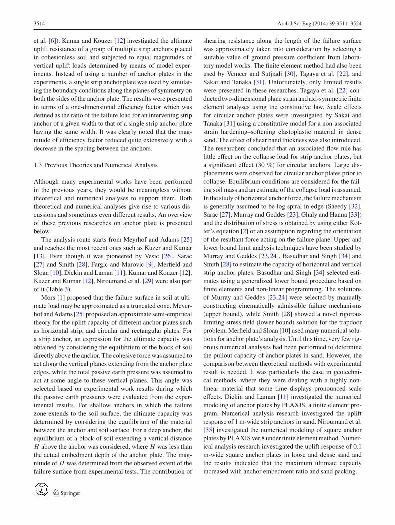
Fig. 12 Author’s empiricalformula of break-out withembedment ratio L/D forirregular-shaped anchors inloose sand
Fig. 13 The author’s empiricalformula of break-out withembedment ratio L/D forirregular-shaped anchor in densesand
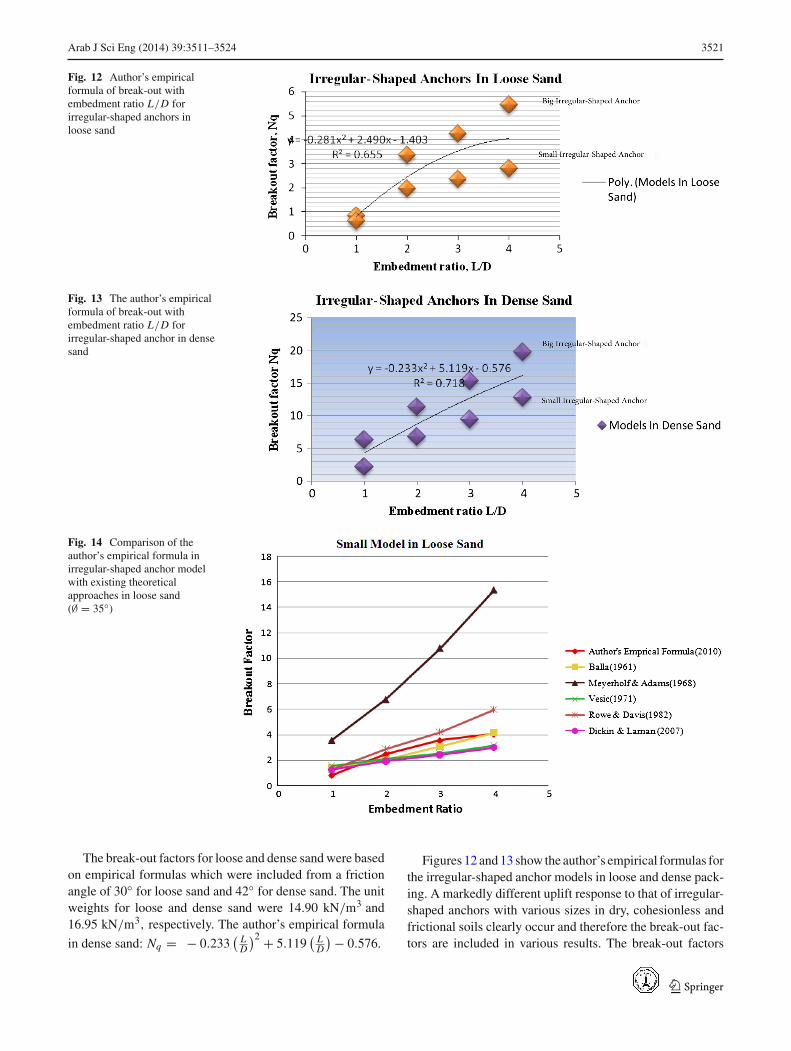
Fig. 14 Comparison of theauthor’s empirical formula inirregular-shaped anchor modelwith existing theoreticalapproaches in loose sand(∅ = 35◦)
The break-out factors for loose and dense sand were basedon empirical formulas which were included from a frictionangle of 30◦ for loose sand and 42◦ for dense sand. The unitweights for loose and dense sand were 14.90 kN/m3 and16.95 kN/m3, respectively. The author’s empirical formula
in dense sand: Nq = − 0.233( L
D
)2 + 5.119( L
D
) − 0.576.
Figures 12 and 13 show the author’s empirical formulas forthe irregular-shaped anchor models in loose and dense pack-ing. A markedly different uplift response to that of irregular-shaped anchors with various sizes in dry, cohesionless andfrictional soils clearly occur and therefore the break-out fac-tors are included in various results. The break-out factors
123
3522 Arab J Sci Eng (2014) 39:3511–3524
Fig. 15 Comparison of theauthor’s empirical formula inirregular-shaped anchor modelwith existing theoreticalapproaches in loose sand(∅ = 35◦)
Fig. 16 Comparison of theauthor’s empirical formula inirregular-shaped anchor modelwith existing theoreticalapproaches in dense sand(∅ = 42◦)
Fig. 17 Comparison of theauthor’s empirical formula inirregular-shaped anchor modelwith existing theoreticalapproaches in dense sand(∅ = 42◦)
were exported by a special equation to the ultimate pulloutload capacity. The relationship between the author’s empiri-cal formula and the embedment ratios was derived from the
current research, as well as many theoretical approaches forloose and dense sand. The relationships between break-outfactors and embedment ratios were derived from a number
123
Arab J Sci Eng (2014) 39:3511–3524 3523
of theoretical approaches are shown semi-logarithmically inFigs. 14, 15, 16 and 17 for loose sand and dense sand, respec-tively, which also includes the author’s empirical formulas forcomparison purposes. The author’s empirical formula basedon irregular-shaped anchors is compared with many exist-ing theories on symmetrical anchor plates, such as Balla [2],Meyerhof and Adams [25], Vesic [26], Rowe and Davis [19]and Dickin and Laman [11]. The existing theories resultedfrom the findings of many researches conducted on anchorplates with finite element method analysis, limit equilibriumanalysis and limit analysis.
According to results, the finite element method of Balla[2] appears to be the best theoretical method and closer to thephysical results. A higher value of safety factor needs to beconsidered in the design by Meyerhof and Adams [25]’s the-ory in the deep anchor plates, whereas a lower value of safetyfactor needs to be considered in the design in the analysis ofDickin and Laman [11]’s theory.
Meyerhof and Adams [25] showed the best theoreticalmethod and closer to the current physical results.
Dickin and Laman [11]’s numerical results and values areclosest in agreement with the current physical results. In thecurrent step, Meyerhof and Adams [25]’s theory was not asafety method for design in deep anchor plates.
In the big irregular-shaped anchors, Meyerhof and Adams[25]’s findings appears to be the best theoretical methodcloser to values in dense sand.
5 Conclusion
The experimental results showed the limited ultimate pulloutload capacity of the irregular-shaped anchor models under theinfluence of embedment ratio and sand density. The resultsshowed the failure surfaces around the irregular-shaped anchorat the shallow and deep level that are similar to the rupturesurface of Balla [2], Dickin and Laman [11] and Meyerhofan Adams [25]. The results showed that the failure surfacein loose sand was lower than in dense packing. In addition,no overall agreement was found between the author’s find-ings and the existing theories regarding the break-out loadfactor and the embedment ratio. This was expected sinceresearchers used various systems and parameters in theirwork, although the irregular-shaped anchor system was usedwithout any grout and excavation during the rotation. How-ever, close agreement with the existing theories for partic-ular embedment ratios and the break-out factor was found.The author’s prediction based on the break-out factor forall of the embedment ratios shows almost the best agree-ment with Balla [2] and Dicken and Laman [11] ’s theoriesin loose sand and Meyerhof and Adams [25]’s findings indense sand. According to the comparison between results andexisting theoretical analysis, the results show a close agree-
ment between the irregular-shaped anchors with symmetri-cal anchor plates in the break-out factors and the embedmentratios in loose and dense sand.
References
1. Mors, H.: The behavior of most foundations subjected to tensileforces. Bautechnik. 36(10), 367–378 (1959)
2. Balla, A.: The resistance of breaking-out of mushroom foundationsfor pylons, In: Proceedings of 5th international conference on soilmechanics and foundation engineering, Paris 1, 569–576 (1961)
3. Sutherland, H.B.: Model studies for shaft raising through cohesion-less soils. In: Proceedings of 6th international conference on soilmechanics and foundationengineering, 2, 410–413 (1965)
4. Baker, W.H.; Konder, R.L.: Pullout load capacity of a circular earthanchorburied in sand. Highw. Res. Rec. 108, 1–10 (1966)
5. Adams, J.I.; Hayes, D.C.: The uplift capacity of shallow founda-tions. Ont. Hydro-Res. Q., 1–13 (1967)
7. Dickin, E.A.: Uplift behavior of horizontal anchor plates in sand.J. Geotech. Eng. 114(11), 1300–1317 (1988)
8. Frydman, S.; Shamam, I.: Pullout capacity of slab anchors in sand.CanGeotech. J. 26, 385–400 (1989)
9. Fargic, L.; Marovic, P.: Pullout capacity of spatial anchors. J. Eng.Comput. 21(6), 598–700 (2003)
10. Merifield, R.S.; Sloan, SW.: The ultimate pullout capacity ofanchors in frictional soils. Can. Geotech. J. 43(8), 852–68 (2006)
11. Dickin, E.A.; Laman, M.: Uplift response of strip anchors in cohe-sionless soil. J. Adv. Eng. Softw. 1(38), 618–625 (2007)
12. Kumar, J.; Kouzer, K.M.: Vertical uplift capacity of horizontalanchors using upper bound limit analysis and finite elements. Can.Geotech. J. 45, 698–704 (1994)
13. Kuzer, K.M.; Kumar, J.: Vertical uplift capacity of two interferinghorizontal anchors in sand using an upper bound limit analysis. J.Comput. Geotech. 1(36), 1084–1089 (2009)
14. Niroumand, H.; Nazir, R.; Kassim, K.A.: The performance of elec-trochemical remediation technologies in soil mechanics. Int. J.Electrochem. Sci. 7(6), 5708–5715 (2012)
15. Hanna, T.H.; Carr, R.W.: The loading behavior of plate anchors innormallyand over consolidated sands. In: Proceedings of 4th inter-national conference on soilmechanics and foundation engineering,Budapest, 589–600 (1971)
25. Meyerhof, G.G.; Adams, J.I.: The ultimate uplift capacity of foun-dations. Can. Geotech. J. 5(4), 225–244 (1968)
123
3524 Arab J Sci Eng (2014) 39:3511–3524
26. Vesic, A.S.: Breakout resistance of objects embedded in ocean bot-tom. J. Soil Mech. Found. Div. ASCE 97(9), 1183–1205 (1971)
27. Sarac, D.Z.: Uplift capacity of shallow buried anchor slabs. In:Proceedings, 12th international conference on soil mechanics andfoundation engineering, 12(2), 1213–1218 (1989)
28. Smith, C.C.: Limit loads for an anchor/trapdoor embedded in anassociative Coulomb soil. Int. J. Numer. Anal. Method Geomech.22(11), 855–865 (1998)
29. Niroumand, H.: Performance of shred tires and wood particles inearth bricks. In: 2nd International conference on sustainable con-struction materials and technologies, pp. 1083–1091 (2010)
30. Vermeer, P.A.; Sutjiadi, W.: The uplift resistance of shallow embed-ded anchors. In: Proceedings of 11th international conferenceon soil mechanics and foundation engineering, San Francisco, 3,1635–1638 (1985)
31. Sakai, T.; Tanaka, T.: Scale effect of a shallow circular anchor indense sand. Soils Found. Jpn. 38(2), 93–99 (1998)
33. Ghaly, A.; Hanna, T.H.: Eggects of K0 and Overconsolidation onUplift Capacity. J. Geotech Eng. ASCE. 118(9), 1449–1469 (1994)
34. Basudhar, P.K.; Singh, D.N.: A generalized procedure for pre-dicting optimallower bound break-out factors of strip anchors.Geotechnique, 44(2), 307–318 (1994)
35. Niroumand, H.; Kassim, K.A.; Nazir, R.: Uplift response of hori-zontal strip anchor plates in cohesionless soil. Electron. J. Geotech.Eng. 15 R, 1967–1975 (2010)
36. Khulief, Y.A.; Al-Sulaiman, F.A.; Arif, A.; Ben-Mansour, R.; Al-Qutub, A.; Anis, M.: Computational tradeoff in modal characteris-tics of complex rotor systems using FEM, Arab. J. Sci. Eng. 37(6),1653–1664 (2012)
37. Vesic, A.S.: Expansion of cavities in infinite soil mass. J. SoilMech.Found. Div. ASCE. 98(3), 265–290 (1972)
38. Ovesen, N.K.: Centrifuge tests of the uplift capacity of anchors. In:Proceedings of the 10th international conference on soil mechanicsand foundation engineering location, Stockholm, Sweden, 1, 717–722 (1981)
39. Bouazza, A.; Finlay, T.W.: Uplift capacity of plate anchors in atwo-layeredsand. Geotechnique, 40(2), 293–297 (1990)