Upper bound on the diffraction efficiency of phase-only fanout elements Ulrich Krackhardt, Joseph N. Mait, and Norbert Streibl For one-dimensional binary-phase [(0, r) and (0, non-7r)] fanout elements and for one-dimensional continuous or multilevel quantized phase fanout elements, an upper bound on diffraction efficiencyis presented for fanouts ranging from 2 to 25. The upper bound is determined by optimizing with respect to the array phase the upper bound on diffraction efficiencyfor a coherent array. To determine the upper bound for binary-phase gratings, restrictions on the array phase are imposed. For fanouts that are > 5, the upper bound on the diffraction efficiency for continuous phase fanouts ranges between 97 and 98%;for (0,7r)-binary-phasefanouts the upper bound ranges between 83 and 84%;and for (0, non-7r)-binary-phase, between 87 and 88%. Key words: Phase-only gratings, array generators, maximum diffraction efficiency. I. Introduction The application of Fourier phase-array generators to optical computing' has spurred the development of a number of algorithms 7 for designing phase-only gratings. Most of these are optimization algorithms wherein a Fourier phase function is determined so that the resulting spot sources are generated uni- formly and with high diffraction efficiency."4Design results cited in the literature confirm the efficacy of the algorithms; binary phase gratings reported to have a better than 80% diffraction efficiency and continuous phase gratings having as much as 90% efficiency are not now uncommon. 8 As significant as these results are, their performance relative to the maximum diffraction efficiency possible has hereto- fore not been investigated as far as we know. Re- cently, however, Wyrowski 9 has derived an expression that allows at least an upper bound on diffraction efficiency to be determined when images are gener- ated using phase-only Fourier filters. If the magnitude and phase of an image are speci- fied and a phase-only Fourier filter is used to generate it, a relationship exists between the Fourier spectrum When the research was performed the authors were with the Physikalisches Institut der Universitat Erlangen-Nfirnberg, Lehrstuhl fur Angewandte Optik, Staudtstrasse 7/B2, D-8520 Erlangen, Germany. J. N. Mait's permanent address is Harry Diamond Laboratories, 2800 Powder Mill Road, Adelphi, Maryland 20783. Received 28 January 1991. 0003-6935/92/010027-11$05.00/0. t 1992 Optical Society of America. of the desired image and the upper bound on diffrac- tion efficiency with which the image can be generated. This relationship provides a means for determining an upper bound on the diffraction efficiency when spot arrays are generated using phase-only filters. The expression for the upper bound on efficiencyis discussed in Section II and is followed in Section III by a discussion of its application to array generation. It is shown that a critical parameter for achieving high diffraction efficiencyis the phase associated with the spot array. Section III also discusses the con- straints on the spot-array phase that arise because of the nature of the phase grating, e.g., a binary phase or a continuous phase. The results of optimizingWyrows- ki's equation subject to these constraints and those of high diffraction efficiency are presented in Section IV for one-dimensional (1-D) binary-phase-array genera- tors, both (0, r)-and (0, non-rr)-binary phase, and for 1-D continuous phase-array generators for array sizes ranging from 2 to 25. Section V considers the implications of this work for two-dimensional (2-D) spot arrays, and Section VI contains some concluding remarks. II. Phase-Only Filters Because of its nonabsorptive nature, a phase-only filter is efficient with regard to the transmission of light energy. Assuming that the filter is a thin diffractive element, we can describe this transmission by P(u) = exp[ji(u)]. (1) 1 January 1992 / Vol. 31, No. 1 / APPLIED OPTICS 27
Transcript
Upper bound on the diffraction efficiency ofphase-only fanout elements
Ulrich Krackhardt, Joseph N. Mait, and Norbert Streibl
For one-dimensional binary-phase [(0, r) and (0, non-7r)] fanout elements and for one-dimensionalcontinuous or multilevel quantized phase fanout elements, an upper bound on diffraction efficiency ispresented for fanouts ranging from 2 to 25. The upper bound is determined by optimizing with respect tothe array phase the upper bound on diffraction efficiency for a coherent array. To determine the upperbound for binary-phase gratings, restrictions on the array phase are imposed. For fanouts that are > 5,the upper bound on the diffraction efficiency for continuous phase fanouts ranges between 97 and 98%; for(0, 7r)-binary-phase fanouts the upper bound ranges between 83 and 84%; and for (0, non-7r)-binary-phase,between 87 and 88%.
Key words: Phase-only gratings, array generators, maximum diffraction efficiency.
I. Introduction
The application of Fourier phase-array generators tooptical computing' has spurred the development of anumber of algorithms 7 for designing phase-onlygratings. Most of these are optimization algorithmswherein a Fourier phase function is determined sothat the resulting spot sources are generated uni-formly and with high diffraction efficiency."4 Designresults cited in the literature confirm the efficacy ofthe algorithms; binary phase gratings reported tohave a better than 80% diffraction efficiency andcontinuous phase gratings having as much as 90%efficiency are not now uncommon.8 As significant asthese results are, their performance relative to themaximum diffraction efficiency possible has hereto-fore not been investigated as far as we know. Re-cently, however, Wyrowski9 has derived an expressionthat allows at least an upper bound on diffractionefficiency to be determined when images are gener-ated using phase-only Fourier filters.
If the magnitude and phase of an image are speci-fied and a phase-only Fourier filter is used to generateit, a relationship exists between the Fourier spectrum
When the research was performed the authors were with thePhysikalisches Institut der Universitat Erlangen-Nfirnberg,Lehrstuhl fur Angewandte Optik, Staudtstrasse 7/B2, D-8520Erlangen, Germany. J. N. Mait's permanent address is HarryDiamond Laboratories, 2800 Powder Mill Road, Adelphi, Maryland20783.
Received 28 January 1991.0003-6935/92/010027-11$05.00/0.t 1992 Optical Society of America.
of the desired image and the upper bound on diffrac-tion efficiency with which the image can be generated.This relationship provides a means for determiningan upper bound on the diffraction efficiency whenspot arrays are generated using phase-only filters.
The expression for the upper bound on efficiency isdiscussed in Section II and is followed in Section IIIby a discussion of its application to array generation.It is shown that a critical parameter for achievinghigh diffraction efficiency is the phase associated withthe spot array. Section III also discusses the con-straints on the spot-array phase that arise because ofthe nature of the phase grating, e.g., a binary phase ora continuous phase. The results of optimizing Wyrows-ki's equation subject to these constraints and those ofhigh diffraction efficiency are presented in Section IVfor one-dimensional (1-D) binary-phase-array genera-tors, both (0, r)- and (0, non-rr)-binary phase, and for1-D continuous phase-array generators for arraysizes ranging from 2 to 25. Section V considers theimplications of this work for two-dimensional (2-D)spot arrays, and Section VI contains some concludingremarks.
II. Phase-Only Filters
Because of its nonabsorptive nature, a phase-onlyfilter is efficient with regard to the transmission oflight energy. Assuming that the filter is a thindiffractive element, we can describe this transmissionby
If P(u) is used as a Fourier plane filter in a coherentoptical processor, the desired design condition of theresponse of P(u) is
p(x) = aq(x), x E X, (2)
where q(x) is the desired response, p(x) is the re-sponse of the filter P(u) (i.e., the inverse Fouriertransform), a is a proportionality constant, and X isthe region over which the condition is to be satisfied.
Since few images of interest have Fourier trans-forms that are phase only, it is not possible to satisfythe conditions of Eq. (2) throughout the image plane,i.e., X (-oo, o). However, through design, Eq. (2)can be satisfied either approximately over the entireimage plane or exactly over a finite region X. Thelatter is more commonly used for array generatordesign.
Since the signal window X is not the entire imageplane, the efficiency, which is defined as the fractionof the input energy used to generate q(x),
= f ,p(x) Idx, (3)
is <100%. Because the efficiency can also be con-trolled through design, various optimization algo-rithms such as simulated annealing,2 3 gradient de-scent,4 and an iterative Fourier algorithm,5 have beensuccessfully applied to the design of high-diffraction-efficiency phase-only elements.
Although reported diffraction efficiencies of > 80%for binary-phase elements and > 90% for multilevelor continuous-phase elements are accepted as good,how these numbers compare with the maximumpossible diffraction efficiency has been addressed onlyrecently. The following equation from Wyrowski9specifies the upper bound on diffraction efficiencyassuming that P(u) is used to produce the image q(x)that has both magnitude and phase specified:
~. 2WIdlfI IQ(u)d(aL~ <. 4
The function Q(u) is the Fourier transform of q(x). Itshould be noted that the efficiency bound assumes azero error within the signal window. Since efficiencyis simply a measure of the total energy within thesignal window, it is possible to achieve efficienciesthat are greater than this bound but the results willcontain errors.
However, the application of Wyrowski's equation islimited in that both the magnitude and the phase ofq(x) must be specified. For many applications, such asoptical interconnects, only the specification of theimage magnitude is essential; the specification of thephase of q(x) is not critical. Thus the image phase is afree parameter available for design. It is used here to
determine the upper bound on diffraction efficiencyfor array generators.
One final note concerning inequality (4) is requiredbefore continuing. Although it is possible for theright-hand side of inequality (4) to be larger thanunity, which might suggest that 100% diffractionefficiency can be achieved, none of the upper boundscalculated herein exceeds this physical limit. Theimplications of an upper bound that is greater thanunity are not yet fully understood.
III. Array Generators
In the following discussion we limit the determina-tion of the diffraction efficiency upper bound to a classof phase-only filters that is capable of generating anarray of point sources: Fourier phase gratings. Todetermine the upper bound for a specific array pat-tern q(x), it is necessary to express the transformQ(u) of the desired array as a function of a discrete setof array-phase values and maximize the right-handside of inequality (4) with respect to these phases.
However, restrictions on the array phase will existdependent on the nature of the phase grating. Threetypes of phase grating are considered: a continuousphase and a multilevel quantized phase; a (0, non-Tr)-binary phase; and a (0, Tr)-binary phase. The genera-tion of both odd numbered spot arrays and evennumbered spot arrays is also considered.
A. Continuous Phase and Multilevel Quantized PhaseGratingsMultilevel (more than two) quantized phase gratings7and continuous-phase gratings are both capable ofgenerating an arbitrary complex image over a finiteregion. Thus, as will be shown, no restrictions existon the phase of q(x). The form of such gratings is nowconsidered so that arrays of odd and even numberedspots are produced.
1. Odd Numbered Spot ArraysIf P(u) represents the basic period of a grating, P(u) isreplicated as follows to generate an array of oddnumbered spots:
P(u) = P(u) * comb(u), (5a)
which generates the response
N
p0 (X) = p(x)comb(x) = 2 (n)8(x - ),n--N
(5b)
where
i(x) = 1 P(u)exp(j2irxu)du (6)
(see Fig. 1). The examination of Eq. (5) reveals thatthere are no restrictions on the resulting phases ofthe generated sources; thus, for an odd numberedspot array generator, the function q(x) and its corre-
Fig. 1. Representation of (a) grating phase +(u) and (b) responsep(x) for an odd numbered spot array.
sponding transform are given by
N
qj(x) = a.,, exp(jO0 ,.)8(x n),N
Q,(u) = E a0 ,, exp( jO,n)exp(-j2irun).n--N
(7a)
(7b)
Note that when the amplitudes an are specified andEq. (7b) is substituted into inequality (4), the onlyparameters that affect diffraction efficiency are the2N + 1 phases 0On. (A constant phase and a linearphase shift can be arbitrarily set to zero withoutaffecting the diffraction efficiency. Therefore the num-ber of free parameters is 2N - 1, which is two lessthan the total number of phases.)
2. Even Numbered Spot ArraysTo generate an array of spots having an even numberof sources, the replication is altered'0 :
Note, as represented in Fig. 2, that all the spots are offaxis.
Again, because no restrictions exist on the result-ing phases, for an even numbered spot array theresponse is
N-lqe(X) = I aen exp(jO,n)8(X -n -1/2);n=-N
(9a)
X
(b)
Fig. 2. Representation of (a) grating phase +(u) and (b) responsep(x) for an even numbered spot array.
N-1
Qe(U) = as,n exp(jO,,n)exp[-j2rru(n + 1/2)]n=-N
N-1
= exp(-jIru) E a,,n exp(jO,,)exp(-j2-rrun),
(9b)
and the 2N phases n provide a degree of designfreedom for maximizing diffraction efficiency. (Thenumber of free phases is 2N - 1, which results fromarbitrarily setting to zero either a linear phase shiftor a constant phase without affecting diffractionefficiency.)
B. Binary-Phase Gratings
If it is possible to realize either a continuous phasefunction, as is necessary for a kinoform, or multiplequantized phase levels (more than two) during fabri-cation, no restrictions exist on the phase function4(u) and thus no restrictions on the phase on. How-ever, if the phase function 4(u) is quantized to onlytwo levels, restrictions are placed on the phase of thegrating response. A binary-phase grating can beexpressed in general by
P(u) = rect(u) + [exp(j4) - 1(u), (10)
where the function $(u) is a (0, 1)-binary amplitudefunction.
1. Odd Numbered Spot ArraysIf P(u) is replicated to generate an odd numbered spotarray, the response is
Since (u) is a real function, its transform (n) istherefore Hermitian; i.e., u(n) = a*(-n).
If 4) = rr, the off-axis components, n • 0, are givenby
(12a)pO,,(n) = -2ur(n)
and the on-axis component, n = 0, by
p,,(0) = 1 - 2r(O). (12b)
The term (0) is simply the average value of thebinary-amplitude function E(u), which is always realand positive:
U(0) = f 1/2 (13)
Thus, if an odd array is to be generated by a (0,r)-binary-phase function, because of the Hermitian
symmetry of u(n), the phases on are restricted so thaton = - n, which also implies that 00 = 0. The responseq(x) and corresponding transform Q (u) are now givenby
and the free parameters are now reduced to tiphases 0,1 -O N (Because ,0 = 0, only a linear pshift can be arbitrarily set to zero. The number olphases is therefore N - 1.)
If 4) •- Trr, evaluation of the response yields fioff-axis spots
130,(n) = [exp(j - 1]a(n)= 2 sin /2 exp(jJ/2)u(n),
Q+(u) =j exp(jJ/2) [aO,o exp( j 00O)N 1
+ 2 E ao,,, cos(27run - k.)-n 1
(16b)
where
0o = * - (/2 - 'n12.
Note that when a non-7r grating phase is used, theresponse phases remain conjugate symmetric, on =
- n, with the exception that O, is nonzero. The freeparameters now are the N + 1 phases 0, - o,N' (Inthis case the nonzero phase of the on-axis spot issignificant, and again only a linear phase shift can beset to zero without affecting the diffraction efficiency.The number of free phases is therefore N.)
2. Even Numbered Spot ArraysIf an even numbered spot array is generated by usinga general binary-phase grating, the description of thegrating must be altered:
Note that the Hermitian symmetry of the off-axisspots is maintained but that the spots are nowmultiplied by a complex constant. The on-axis spotalso no longer has a zero phase. Therefore the spotarray and its transform are constrained to be
For an even numbered spot array the use of anarbitrary binary-phase grating simply scales the re-sponse by a complex constant but does not in anyother way restrict it. Therefore, because of the evensymmetry of the sinc function and the Hermitiansymmetry of a(x), the desired grating response and itstransform are given by
N-iq,,4 (x) = 2 a,,n[exp(JO,,TnW(x - n - 1/2)
n=0
+ exp(-jO,,,)8(x + n + 1/2)]; (18a)
N-i
Qe,,(u) = 2 N a,, cos[2iru(n + 1/2) Oen], (18b)
and the free parameters available for maximizingdiffraction efficiency are the N phases 01 - N (N - 1after arbitrarily setting a linear phase shift to zero).Because the maximum diffraction efficiency occurswhen 4 = r, the complex constant identified in Eq.
30 APPLIED OPTICS Vol. 31, No. 1 1 January 1992
(17b) has been neglected in Eqs. (18). When 4) X r,the diffraction efficiency is simply reduced by sin2 4)/2.
IV. Maximization
The specification of the form of the desired responsetransform makes it possible to determine the upperbound on diffraction efficiency for a phase-only arraygenerator; the right-hand side of Eq. (4) is maximizedwith respect to the set, or restricted set, of phases 0,.The magnitude of the spot array must also be speci-fied, and design of a fanout element is assumed, i.e.,a,, = 1 for all n. Fanouts ranging from 2 to 25 areconsidered. Two algorithms, the downhill simplexmethod and simulated annealing,"1 were used toperform the maximization and insure the validity ofthe results.
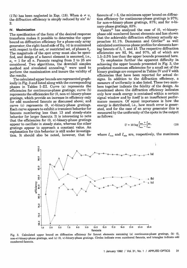
The calculated upper bounds are represented graph-ically in Fig. 3 and listed along with the correspondingphases in Tables I-III. Curve (a) represents theefficiencies for continuous-phase gratings; curve (b)represents the efficiencies for (0, non-7r)-binary-phasegratings, which provide an increase in efficiency onlyfor odd numbered fanouts as discussed above; andcurve (c) represents (0, r)-binary-phase gratings.Each curve appears to exhibit a transient behavior forfanouts numbering less than 13 and steady-statebehavior for larger fanouts. It is interesting to notethat the efficiencies for (0, mr)-binary-phase gratingsappear to oscillate in steady state, whereas the othergratings appear to approach a constant value. Anexplanation for this behavior is still under investiga-tion. It should also be noted, however, that for
fanouts of > 5, the minimum upper bound on diffrac-tion efficiency for continuous-phase gratings is 97%;for non-rr-binary-phase gratings, 87%; and for rr-bi-nary-phase gratings, 83%.
Vasara'2 has analyzed the case of (0, vr)-binary-phase odd numbered fanout elements and has shownthat the achievable diffraction efficiency actually ap-proaches 81.1%. Dammann and Gdrtler 5 as wellcalculated continuous-phase profiles for elements hav-ing fanouts of 3, 7, and 13. The respective diffractionefficiencies are 92, 94, and 97%, all of which are1.5-3.5% less than the upper bounds presented here.
To emphasize further the apparent difficulty inachieving the upper bounds presented in Fig. 3, thepredicted maximum efficiencies for a small set of thebinary gratings are compared in Tables IV and V withefficiencies that have been reported for actual de-signs. In addition to the diffraction efficiency, ameasure of uniformity is also listed. These two num-bers together indicate the fidelity of the design. Asmentioned above the diffraction efficiency indicatesonly how much energy is contained within a certainsignal window and by itself is an insufficient perfor-mance measure. Of equal importance is how theenergy is distributed, i.e., how much error is gener-ated, and for the case of an array generator this ismeasured by the uniformity of the spots in the outputas follows:
U = 10 log I Imm
Ima - min(19)
where Im., and Imin are, respectively, the maximum
A,
Al
A
. .
.0.
.....Q
6~~~~~~~~~~~~~~~~~~~~~~~~~~
- ..
. ... ... . a-II
II
.0 3.0 5.0 7.0 9.0 11.0 13.0 15.0fanouts
17.0 19.0 21.0 23.0 25.0
Fig. 3. Calculated upper bound on diffraction efficiency for fanout elements assuming (a) continuous-phase gratings, (b) (0,
non-ir)-binary-phase gratings, and (c) (0, r)-binary-phase gratings. Circles indicate even numbered fanouts, and triangles indicate odd
on c- on 00-ononoo 00 � 0 m ro romon onon.-o on 00 0- on 0on 00 on on 00 ro on on 00 - 0 ro 0 - 00 00 00 0 00 00 00 ,0 00on o- 00 Om o,,,� 0 on on 0 roonono-.om,, 00
00 6 02 9 9 0- 9 9 0- 00 00 on on- 6 o on on on - e - 6 on -4 6 oo 0-4 6I I I I I I I I I Ion � oo monoonono oo mom 0000000 monon mon 000 0 Oo-noon onon 0 0 0-00 on0000.-.mononon000-� 0 O000-00onononm.no
0 0o,o 000000 000-000�onmo 000-0000. romeo, on on00 0- 00 0 0 00 0- 00 0 00 00 00 00000 00 00 00 00 - 0 on 00 00 0 0 00 00 00 00 0 00 on 00 00 0000 oi on 6 6 onoo on.-, 0 6 6 6 -4 oS 6 - 00 00 0 0 00 00I I I I I I I I I I I
00 00 00 00 00 0 00 00 0 0 m 00 00 0 00 on 00 00 0000 0 00 000-0000000 0 0 oononono0- 00 00 on on 0m - 00 00 0- 00 0 00 on 00 00 0 0 0 00 00 on on 0 000-0000o000 00 on 00 on 00 00 00 on 00 0 0 on on r- on 00 00 m 00 00 On onon 00 000-0000000000 0 on 000000000000- 00 00 0 0000 00 0 0- 0 0 00 00 00 0 0 0 00 00 00 0 0 0- 0 on On00 00 0 0 00 0 00 0 - 0 0 0 00 0 00 0 00 0 0 00 00 00I I I I I I I I
00 0 000000000- 0 0 0- 0 0 0- 0 00-000000 00 0 00000000000000 00 on 0 on 0 0 0 0 0 0000000000000000 00000000000-00 00 00 00 0 on 00 00 00000-00000000 000000 0000000000000000 00 on 000 00 00 00 0- 0 00 00 00 0 0 00 00 00 0 0- 00 00 00 0000 0 00 m 9 0 0 0 0 0 0 0 0- 0 0- 00 - 00 06 6 6 00 �0 00 on 0 0 00 0 0 00 0 0 00 00 00 00 0 0 0I I I I I t r I I000 0000onoo ononon on 0 oonon on 00000 0000000000-000000000 00 0 0 0 000000000000-00 0.000 00 OOnonon0-...oon 0 0 0000000-00000 0000000 00-.000.- 0 0 0 - 00 00 - 00 00 0 on9 0 9 00 0 00 0- 00 0 00 00 0000 .-4 6 oS roononononon 0 0 o00ononmro.-,on
0 ,.,I I I I I I I I I00 oOonmononoon m ononmononmon 00 on00 00 00 00 on 00 00 0 0 00 00 00 00 00 00 00 0000 0- 00 0 00 00 00 0 0 00 00 00 0 00 0- 00 00 00000 ���o�-ooomon mOon 0000 mono on 0000� 00 9 9 00 9 00 00 0- 0 0 0- 00 00 00 00 9 9 00 0000 0 0 0 00 00 0 00 00 6 6 oS 6 00 0 0 0 00I I I I I I
32 APPLIED OPTICS I Vol. 31, No. 1 I 1 January 1992
o - t- to- 10010 LO o CD' 0 CD 0 Co Go cq m -4 CO LO
c. 0 Go Go CO M o > Com O4 0 o l N,-4m o4 C=oo to LO N Lo 1- c--I Go CO aCq cq C Co C Ci 't ,- C -r s
I c I I I N - - 6 Q i NI I I I I I
co cN ' C> 10 C Go > > Co 0 0 - 1t I"Z Id n-I 1 C > 100 O 01 0
l - Co n-S - n-4 Cl C> C> 0 0 C O>0C C> Co C CD 4 10 Cl 0 0 cO 010 C 00 Co Co 0 10 Cl 0 C CDO ClCO ' 00 Co 0 n1- t o C m ) 0 000cl - -4 Cl O 6 O 0 0 O 0; O -OI I I 1 I I 1
LoCl CD 0 CO -s CO m o 1 N CD CD O >- o 0 0 0 G o -I
10 n- 1- Cl C 02 : NG L- CO 0 C C C lCD o Co 0 C> CO 0 0cN n - O-C- i -iI I I I 1
ns CO 0O
10 ,- CD10 CD GoGo o Q-
00 00 C
I
o ,4 0 co -4 10010 C> Crot- E- 0 o o 00 CO ,- Go C<C Go CO 0 C'A 0 qO t CO > C> 0- CD 00 00 01 0 CDo Cl O 0 -I CO Ild4 Cl O -s cmO 00 0 . CO 00 N -4 LO1 CL 10 CO 0o q 0O n-s C Cl CO C Cl s ClOn -O 0Ci -1 I 0 0 l _ _iNO O Cl
I 1 I 1
C> t- Go LO 1 > l Cl, CC> "r n-4 C d > d "t -C>C> C - 02 C N n- dC 10 I CD Co Co C> > 002 Cl 10 o Co Co Go C 10Co O I --I 0 Co Go CO6 OO -- 4 _ Cl
Co 0 CD cl 10C Cl C 02CO1 00 0 0 >CO N 1- n-4 10CO 2 C t- 00L- Co 10 CD0 ,- 0 ClI I I
Co C N ' CN 10 Go 0 00 Co 00 0 mo 10 C N ,I N C o> - CD CD 4 D - O C - - .. I C -S C>
cs C o o o CO 00 C o n- G-o 1 Go 0 cM CO1010 CI 1 Cl G Go G Cm l CO Cl Go G Go Cl 1N l1 U
co t 0) > U o m O C 0 CO Co o o Ct m CD -IO O 0 00 "I O C1 00 C0 D 00 No I 00 00 0C o C O6 C O s- s O 6 O 6 6OO C5 6 6 Ci cQ
I I I I I I I I I
000 n-O CD n-0 ,-4 0D 0O CO0 O 0 00 m0 0 0 C q s 00- 0 _ CS CIl0 00 0D CDo0 _ O cl
CD O0 C:> O 10 C O 1 O C> o 0 ' COco D 10101 1- 0 o 0 C> 10001 o coC 2 Cm tG 0 Cl 1- 0 Co 0 C 0 O > 02 N0 , 1 d 1- 0 o 00 0 CD 0) - l ,- 0 Go t Co 00 CO - 0 COO - CD 0 CoD - 0 0n- Cl1 > n. 1- 10 CO 01 C_ > ,- 1- Cl
ci II6 I q I CD 01IIc 4N
Co -S C O CIO C O LO 10 C Co m0 CO 0 CO N CDO CD O C C 0 CD 0C - t 10 o 10 o 010 Co 10 - CNGo O Go > 10 Co 0 mO 0C 1 > Go Co Goz Go Co CO 02 0 o CDO 02 CO C Go t
0 1- Go CD , -sO---O -s CO Go C> 0-so ~oi6so 6o io --s o HI I I I I I
L>L cl
00
cl t-
oo
coGQoo
0
oO
00-
C>H_o
00
00
00
CSo
CD
aoCO
Go00
C'so
oO
0C,>
CSl
0 I 0 Co 0 ( m D n-S
14 lz CD t CD t 4 m -4 C0 C O 0 Co 0 00 00M ,d 0 C) 0 t M -S Clo
Cli Cli 0 CDi 6 c-i cli c-i Ci _I I I I
1 o -s-- - CIHoooO~ or 10D Co N CD O t O CD C 2
t- 0 CO 02 0 O 02 C0O 1GoC Co C CO 0 CO Co CO G oGo C> n- - o-o-o - > oo0 CO n- CDO CO CO n- CD 0
0 C1 C 0 CO Co 01 CO 6 0 Go 0 e Co 1CCl 02 10 C 0 0 CD C
0 0 0 0 0 0 0 0 00 0000000 00* 0 0 0 0 0 0 0 00 0 - 0 0 0 0 0 00 6 6 6 6 6 6 0I I I I I
0 0 0 0 0 0 0 0
0 0 0 6 6 6 6
0* 0 0 0 0 0 00 0 0 0 0 0 0
0 0 0 0 0 0
0 0 0 0 00 0 0 0 00 6 6 6
06 0 0 00 0 0 0
0 6 6
0 0 00 0 0
Co 9 9
34 APPLIED OPTICS I Vol. 31, No. 1 I 1 January 1992
Table IV. Diffraction Efficiency and Uniformity (in Decibels) for(0, r)-Binary Gratingsa
Real, Even HermitianN Upper Bound Array Array
3 68.74 66.4b 66.4b(mc) (xc)
5 83.80 77.4b 77.4b(xc) (cc)
7 83.07 66.5b 78.6c(Xc) (Xc)
9 80.57 66.3b 70.2c(m) (32.2)
11 82.11 60.6' 78.4c(X) (10.2)
13 84.41 7 0 .0b 74.6c(cc) (28.7)
aA real, even array assumes that the spot array phase is either 0or 7r; the corresponding binary-phase grating is therefore symmet-ric. A Hermitian array assumes no such restrictions on the spot-array phase; thus the grating need not be symmetric.
'Data taken from Ref. 14.cData calculated for this work.
and minimum intensities of the resulting spot arrayp(n). Values of U that are >40 dB are listed asinfinite, which indicates that within the accuracy ofthe calculations the uniformity is perfect. The tablesclearly indicate the trade-off that exists betweenefficiency and uniformity. The acceptability of thistrade-off for a particular design is dependent on theapplication.
The designs presented in Tables IV and V weretaken from Krackhardt and Streibl'4 and from Killatet al." Because of the Hermitian symmetry inherentin the response of the binary-phase grating, it waspossible to extend Dammann's design method7 to anincoherent, or intensity signal, design, which was alsoused to generate some of the results. The extensionrequires the solution of a set of N + 1 nonlinearequations that represent the intensities of the 0ththrough Nth orders in terms of N zeros and a
Table V. Diffraction Efficiency and Uniformity (in Decibels) for(0, non-ir)-Binary Gratings
N Upper Bound Designed
3 93.81 86.5a(x)
5 87.20 77.4(x)
7 89.62 84.4c(23.8)
9 87.74 80.8c(31.4)
11 89.03 84.4e(20.0)
13 86.52 77.2c(25.8)
aData calculated for this work.bData taken from Ref. 14.cData taken from Ref. 15.
constant of proportionality. The phases were left free,and the intensities of the negative orders are given bytheir symmetric twins.
It should be emphasized that the transforms of thesource arrays that use the phases listed in TablesI-III do not yield phase-only signals; they are nearlyphase-only. If these approximate phase-only struc-tures are quantized to a constant magnitude, thedesired array is generated with high efficiency but lowuniformity. However, a continuous-phase grating hasbeen fabricated that generates a fanout of nine with areported 99.33% diffraction efficiency.6 The unifor-mity, as defined by Eq. (19), is 15.8 dB, which is adeviation of 5% in intensity.
The implication from the calculation of the upperbound is that the maximum diffraction efficiency isachieved when the fewest constraints are placed onthe desired spot array, i.e., when only the magnitudesare specified and when multiple phase levels can befabricated. The use of a binary grating imposes aHermitian symmetry on the array, which halves thenumber of degrees of freedom in the image plane andreduces the maximum possible diffraction efficiency.The trade-off between binary and multilevel phasegratings is, however, in the fabrication. Continuousand multilevel phase gratings require additional pro-cessing steps. The use of (0, non-7r)-binary-phasegratings offers the best compromise in terms ofdiffraction efficiency and ease of fabrication but canbe used only when the magnitude of the spot array issymmetric.
V. Two-Dimensional Array Generator Design
That the maximum diffraction efficiency is obtainedwhen the phase of the spot array has no restrictionshas implications in the design of 2-D array genera-tors. In particular array generators that are con-structed from two 1-D arrays in a separable fashionhave more phase restrictions than nonseparable ar-ray generators and thus are not capable of achievingas high a diffraction efficiency.
To see this consider the response of a continuousgrating that produces a 2-D odd numbered array:
P0(u, v) = P(u, v) ** comb(u, v); (20a)
p.(x, y) =(x, y)comb(x, y)
= j (n, m)(x - n,y -m). (20b)m-- n=-oc
Since no phase restrictions exist, the desired arrayand its corresponding transform are given by
M N
q.(xY) = an, exp(jOnm,)8(x - ny - m),m-M n=-N
M N
Qj(u, v) = E E anm exp(jOn,)exp[j2Tr(nu + mv)].m-M n=-N
(21a)
(21b)
If we ignore a constant phase and a linear phase shift,
ble design will generate only 70% diffraction effi-ciency. Thus nonseparable designs are recommendedfor binary gratings. Fortunately, the programming ofsimulated annealing and iterative Fourier algorithmsis unaffected by the dimensionality of the designproblem; the increased dimensionality increases onlycomputation time. This is in contrast to algorithmsthat are based on Dammann's method,7 which do notextend easily to two dimensions.
(C)
** * *--00 * 0
e... e °g-... ° 1*C *O g g e gg. .
(d) (e)
* 0 0 . 0
ge.
(O)
binary phase
Fig. 4. Spot-array locations of free phases that are available toincrease the diffraction efficiency for separable arrays assuming (a)continuous-phase gratings, (b) (0, non-7r)-binary-phase gratings,(c) (0, r)-binary-phase gratings and nonseparable arrays, (d)-(f)similar phase structures. Open circles indicate phases that can bearbitrarily set to zero by removing constant phases and linearphase shifts.
the total number of free phases is (2N + 1) (2M + 1)[see Fig. 4(a)].
If the array generator is separable, the array re-sponse is given by
and the number of free phases is reduced to (2N +1) + (2M + 1). If the array is square and the same 1-Dgrating is used for both axes, the number of freephases is only 2N + 1. This is represented in Figs.4(b) and 4(c).
If a grating is binary phase, Hermitian symmetry isimposed on the array and its response, which effec-tively halves the number of free phases available forimproving diffraction efficiency [Figs. 4(d)-4(f)]. Ifthe grating is nonseparable, the number of phases isgiven by 2NM + N + M + 1. For a separablebinary-phase grating the number of phases is N +M + 1, and, if the grating is square, the number ofphases is only N + 1 when the same solution is usedfor both axes.
The trade-off between designing separable gratingsas opposed to nonseparable gratings is the complexityof the design algorithm versus diffraction efficiency.If a 1-D grating that is capable of producing 97%diffraction efficiency is used in a separable design, theefficiency of the 2-D grating is still larger than 94%.However, as noted in the discussion above, such highdiffraction efficiencies cannot be obtained by binary-phase gratings. A binary-phase grating that producesa diffraction efficiency of 84% when used in a separa-
VI. Conclusions
An upper bound on the diffraction efficiency forphase-only fanout elements has been calculated forfanouts ranging from 2 to 25. The bound is deter-mined by optimizing, with respect to the array phase,Wyrowski's expression for the upper bound on effi-ciency for a phase-only coherent design. For continu-ous-phase fanout elements, the upper bound is be-tween 97 and 98%; for (0, non-r)-binary-phase fanoutelements, it is between 87 and 88%; and for (0,'r)-binary-phase elements, it is between 83 and 84%.Trade-offs between diffraction efficiency and unifor-mity have also been indicated as well as the trade-offbetween the design complexity and diffraction effi-ciency for 2-D designs.
Only the upper bounds on diffraction efficiencyhave been presented in this work. An analysis of themaximum diffraction achievable is equally, if notmore, important. However, except for the small classof grating considered by Vasara, 2 such an analysishas not to our knowledge been presented in theliterature. The difficulty in such an analysis is per-haps the interrelationship between grating represen-tation, diffraction efficiency, and design algorithm.An attempt t understand this relationship is pre-sented in Ref. 16. However, the algorithms presentedin Refs. 2-6 appear to be the most promising forproduction of high-diffraction-efficiency fanout ele-ments.
Joseph N. Mait thanks the Sounderforschungsbere-ich, whose support made possible personal discus-sions with Hans Peter Herzig of Universit6 de Neucha-tel, Antti Vasara and Jan Westerholm of the HelsinkiUniversity of Technology, and Frank Wyrowski ofUniversitat Essen. These discussions, as well as thosewith coauthors Uli Krackhardt and Norbert Streibl,were helpful in the preparation and presentation ofthis work.
References1. N. Streibl, K.-H. Brenner, A. Huang, J. Jahns, J. Jewell, A. W.
Lohmann, D. A. B. Miller, M. Murdocca, M. Prise, and T. Sizer,"Digital optics," Proc. IEEE 77, 1954-1969 (1989).
2. M. R. Feldman and C. C. Guest, "High efficiency hologramencoding for generation of spot arrays," Opt. Lett. 14, 479-481 (1989).
3. J. Turunen, A. Vasara, and J. Westerholm, "Kinoform phaserelief synthesis: a stochastic method," Opt. Eng. 28, 1162-1167 (1989).
4. J. Jahns, M. M. Downs, M. E. Prise, N. Streibl, and S. J.
5. F. Wyrowski, "Coding and quantization techniques in digitalphase holography," in Holographic Optics II: Principles andApplications, G. M. Morris, ed., Proc. Soc. Photo-Opt. In-strum. Eng. 1136, 215-219 (1989).
6. H. P. Herzig, D. Prongu6, and R. Ddndliker, "Design andfabrication of highly efficient fan-out elements," Jpn. J. Appl.Phys. 29, L1307-L1309 (1990).
7. J. N. Mait, "Extensions to Dammann's method of binary-phase grating design," in Holographic Optics: Optically andComputer Generated, I. N. Cindrich and S. H. Lee, eds., Proc.Soc. Photo-Opt. Instrum. Eng. 1052,41-46 (1989).
8. A. Vasara, J. Turunen, J. Westerholm, and M. R. Taghizadeh,"Stepped-phase kinoforms," in Optics in Complex Systems, F.Lanzl, H.-J. Preuss, and J. Weigelt, eds., Proc. Soc. Photo-Opt.Instrum. Eng. 1319,298-299 (1990).
9. F. Wyrowski, "Characteristics of diffractive optical elements/digital holograms," in Computer and Optically Formed Holo-graphic Optics, I. N. Cindrich and S. H. Lee, eds., Proc. Soc.Photo-Opt. Instrum. Eng. 1211, 2-10 (1990).
10. R. L. Morrison, "Symmetries that simplify design of spot-array phase gratings," in Annual Meeting Technical Digest,Vol. 15 of OSA 1990 Technical Digest Series (Optical Society ofAmerica, Washington, D.C., 1990), p. 86.
11. W. H. Press, B. P. Flannery, S. A. Teukolsky, and W. T.Vetterling, Numerical Recipes: The Art of Scientific Comput-ing (Cambridge U. Press, Cambridge, 1986).
12. A. Vasara, "Array generation with periodic Fourier-transformholograms," licentiate thesis (Helsinki University of Technol-ogy, Espoo, Finland, 1989).
13. H. Dammann and K. Gfrtler, "High-efficiency in-line multipleimaging by means of multiple phase holograms," Opt. Com-mun. 3, 312-315 (1971).
14. U. Krackhardt and N. Streibl, "Design of Dammann-gratingsfor array generation," Opt. Commun. 74, 31-34 (1989).
15. U. Killat, G. Rabe, and W. Rave, "Binary phase gratings forstar couplers with high splitting ratio," Fiber Integr. Opt. 4,159-167 (1982).
16. J. N. Mait, "Design of binary-phase and multiphase Fouriergratings for array generation," J. Opt. Soc. Am. A 7, 1514-1528 (1990).