24
GE Sensing Druck UPS-III-IS Intrinsically Safe Loop Calibrator User manual - K0341 II 2 G Ex ib IIC T4 Druck UPS-III-IS Loop Calibrator mA mA ( 24V ) COM V

GESensing
Druck UPS-III-ISIntrinsically Safe Loop Calibrator
User manual - K0341
II 2 G Ex ib IIC T4
Dru
ckU
PS
-III
-IS
Lo
op
Ca
lib
rato
r
mA
mA ( 24V )
COM
V

Approved Service AgentsFor the list of service centres visit our web site:
www.gesensing.comSymbols
This equipment meets the requirements of all relevant European safety directives. The equipment carries the CE mark.
This symbol, on the instrument, indicates that the user should refer to the user manual.
Do not dispose of this product as household waste. Use an approved organisation that collects and/or recycles waste electrical and electronic equipment. For more information:
Contact us at www.gesensing.com
i K0341 Issue No. 2
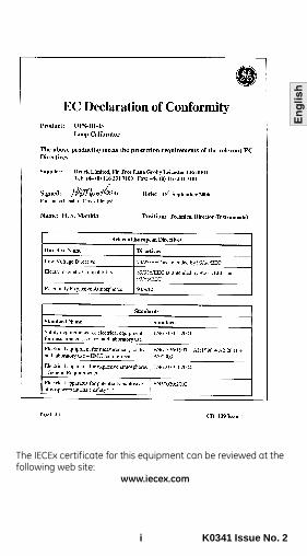
The IECEx certificate for this equipment can be reviewed at the following web site:
www.iecex.com

K0341 Issue No. 2 ii
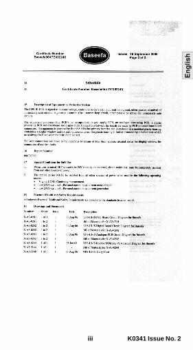
A full copy of the ATEX certificate for this equipment can be supplied, contact us at the following web site:
www.gesensing.com
iii K0341 Issue No. 2

K0341 Issue No. 2 iv

1 K0341 Issue No. 2
UPS-III Intrinsically Safe Loop CalibratorIntroductionThe Druck UPS-III Intrinsically Safe Loop Calibrator can supply power (source mode) and produce readings (measure mode) to perform field calibrations on 2-wire devices. The set-up menu enables the user to “source” or “measure” in either voltage or current and to perform continuity tests. These instructions detail the requirements and operation of the UPS III Intrinsically Safe Loop Calibrator in a hazardous area. Read the whole publication before starting.Installation Requirements in Hazardous AreasMarking detailsSerial number/year of manufacture
1180Baseefa06ATEX0224X IECEx BAS 06.0053XEx ib IIC T4 (-10°C <Ta <+40°C)Druck, LE6 0FH, UK (manufacturer)Requirements and ConditionsRefer to the supply and input/output parameter table.BatteriesWARNING: Only replace batteries in a safe areaOnly use the battery type listed below.RequirementsInstalling should be carried out by qualified plant installation technicians in compliance with the latest issue of EN 60079-14.Special Conditions for UseThis loop calibrator may be used in zones 1 and 2 for industries with any gas group.• Maximum component temperature class T4 (135°C).• Only use 4 x LR6 (size AA), Duracell PROCELL, Duracell
PLUS, ENERGIZER ULTIMATE or GP SUPERALKALINE LR6.Loop Calibrator Casing• Avoid impact sparking when installing in a hazardous area.• Provide additional protection for calibrators that may be
damaged in service.
2
K0341 Issue No. 2 2
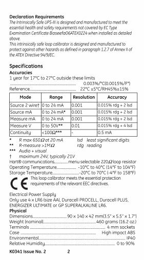
Declaration RequirementsThe Intrinsically Safe UPS-III is designed and manufactured to meet the essential health and safety requirements not covered by EC Type Examination Certificate Baseefa06ATEX0224 when installed as detailed above.This intrinsically safe loop calibrator is designed and manufactured to protect against other hazards as defined in paragraph 1.2.7 of Annex II of the ATEX Directive 94/9/EC.
SpecificationsAccuracies1 year for 17°C to 27°C outside these limits...................................................................... 0.003%/°C(0.0015%/F°)Reference.................................................. 22°C ±5°C/RH45%±15%
* R max 650Ω at 20 mA lsd least significant digits** R-measure >1MΩ rdg reading*** Audio + visual† maximum 24V, typically 21VHart® communications................ menu selectable 220Ω loop resistorOperating Temperature..................... -10°C to 40°C (14°F to 104°F)Storage Temperature.............................-20°C to 70°C (-4°F to 158°F)
This loop calibrator meets the essential protection requirements of the relevant EEC directives.
Electrical Power SupplyOnly use 4 x LR6 (size AA), Duracell PROCELL, Duracell PLUS, ENERGIZER ULTIMATE or GP SUPERALKALINE LR6.PhysicalDimensions.................................... 90 x 140 x 42 mm(3.5” x 5.5” x 1.7”)Weight (nominal)........................................................460 grams (16.2 oz.)Terminals ................................................................................ 4 mm socketsCase ................................................................................ High impact ABSEnvironmental............................................................................................ IP40Relative Humidity........................................................................... 0 to 90%
Mode Range Resolution Accuracy
Source 2 wire† 0 to 24 mA 0.001 0.015% rdg + 2 lsd
Source mA 0 to 24 mA* 0.001 0.015% rdg + 2 lsd
Measure mA 0 to 24 mA 0.001 0.015% rdg + 2 lsd
Measure V 0 to 50V** 0.01 0.015% rdg + 4 lsd
Continuity <100Ω*** - 0.5 mA

3 K0341 Issue No. 2
Table 1Guide to supply and input/output
No. Parameter and conditions
&
Current measurement between mA and COM with external 24V. This mode of operation inserts the apparatus in the current loop by breaking into the circuit and connecting mA (positive) and COM (negative) into the circuit.
Current measurement between mA (24V) and mA with internal 24V. Terminal mA(24V) provides the source of power to supply remote sensor.Special condition for safe use - remote sensor MUST be isolated from all other sources of power.
Voltage measurement between V and COM
Continuity measurement between V and COMSpecial condition for safe use - remote sensor MUST be isolated from all other sources of power.
Current generation between mA and COM with external 24V. This mode of operation inserts the apparatus in the current loop by breaking into the circuit and connecting mA (positive) and COM (negative) into the circuit.
Current generation between mA (24V) and mA with internal 24V. Terminal mA (24V) provides the source of power to supply the remote sensor.Special condition for safe use - remote sensor MUST be isolated from all other sources of power.
1
2
3
44
5
6
7

K0341 Issue No. 2 4
Table 2Supply and input/output parameter
* Special condition for safe use
#220pF consists of 110pF @ 6.51 V max and 110pF @ 1.6V max.
Param. &
Ui 30V 0* 50V 0* 30V 0*
Ii 100mA 0* 100mA 0* 100mA 0*
Pi 1W 0* 1W 0* 1W 0*
U0 6.51V 25.2V 6.51V 6.51V 6.51V 25.2V
I0 14mA 158mA 12mA 8mA 14mA 158mA
P0 22mW 0.995W 20mW 20mW 22mW 0.995W
Ci 220pF# 220pF# 110pF 110pF 220pF# 220pF#
Li 0 0 0 0 0 0
C0 33nF 53nF 10nF 11µF 33nF 53nF
L0 1.5mH 500µH 1.5mH 100mH 1.5mH 500µH
1 2 3 44 5 6 7
5 K0341 Issue No. 2
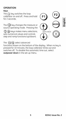
OPERATIONKeys The key switches the loop calibrator on and off. Press and hold for 2 seconds.
The key changes the measure or source operating mode. Pressing the
keys makes menu selections, sets numerical values and controls step and ramp functions (up/down).
The select advanced functions shown on the bottom of the display. When no key is pressed for 10 minutes, the loop calibrator times out and switches off. To disable this automatic time out, select autpower down in the set-up menu.
MODE
F2F1
SPAN CHECK
MODE
F2F1
K0341 Issue No. 2 6
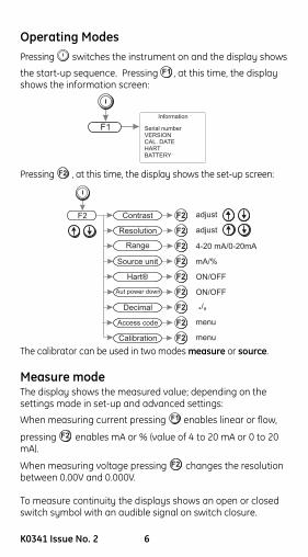
Operating ModesPressing switches the instrument on and the display shows
the start-up sequence. Pressing , at this time, the display shows the information screen:
Pressing , at this time, the display shows the set-up screen:
The calibrator can be used in two modes measure or source.
Measure modeThe display shows the measured value; depending on the settings made in set-up and advanced settings:
When measuring current pressing enables linear or flow,
pressing enables mA or % (value of 4 to 20 mA or 0 to 20 mA).
When measuring voltage pressing changes the resolution between 0.00V and 0.000V.
To measure continuity the displays shows an open or closed switch symbol with an audible signal on switch closure.
F1
F1 Serial numberVERSIONCAL. DATEHARTBATTERY
Information
F2
F2
Resolution adjustF2
Contrast adjustF2
Range 4-20 mA/0-20mAF2
Source unit mA/%F2
Hart® ON/OFFF2
Aut power down ON/OFFF2
Decimal . ,/F2
Access code menuF2
Calibration menuF2
F1
F2
F2

7 K0341 Issue No. 2
Connect the calibrator to the device to be tested:
and Measure mAPress the mode key and select [Measure mA]. An external power supply supplies a maximum of 30 V for the loop. The calibrator measures the current of the loop.
Closed loop current measurement from transmitter test terminal
Measure mA with 24 V* Press mode key and select [Measure mA and 24V]. The calibrator supplies 24 V (maximum) for the loop, maximum 24 mA.*Special condition for safe use, see page 3.
Measure VoltsPress mode key and select [Measure Volts], measure range 50 V, maximum impedance 1 Mohm.
1
+
-
Hazardousarea
Safetybarrier
Safearea
Advanced%
+100.0%+20.000 mA
mA
mA ( 24V )
COM
V
*
2
Hazardousarea
+
-
Safetybarrier
Safearea
Advanced%
+100.0%
+20.000 mA
mA
mA ( 24V )
COM
V
3Advanced
%
+100.0%
+24.000 mA
mA
mA ( 24V )
COM
V
21V
4Advanced
%
+100.0%
mA
mA ( 24V )
COM
V
+50.000 V

K0341 Issue No. 2 8
Continuity Test* Press mode key and select [Continuity Test].
Pressing switches the audible signal on/off.
Source ModeThe display shows the source value in mA or % value of 4 to 20 mA or 0 to 20 mA, linear or flow depending on the settings made in set-up and advanced settings.*Special condition for safe use, see page 3.
Source mAPress mode key and select [Source mA].
Source mA with 24V* Press mode key and select [Source mA and 24V]. The calibrator supplies loop power of: 24 V [maximum], (typically 21V) and 24 mA.*Special condition for safe use, see page 3.
5
+20.000 mA
Step off
+100.0%
mA
mA ( 24V )
COM
V
Rmax = 650 Ohms
6
+
-
Hazardousarea
Safetybarrier
Safearea
Advanced%
+100.0%
mA
mA ( 24V )
COM
V
+12.000 V
I/P
_+
7Advanced%
+100.0%
mA
mA ( 24V )
COM
V
+24.000 mA

9 K0341 Issue No. 2
Advanced Options in a Source mode
Press the key and select mA Source or mA Source & 24V.
Use and (Enter) to select the function.
Press the key (Advanced) and the display shows:Linear simulates linear transmitters.Flow simulates flow transmitters.Valve simulates valve control signals.
Use and (Enter) to select the Advanced option:
Advanced
Note: Ramp function not available for valve selection.
Use to quit. The display returns to the selected source mode with the advanced setting available.
Step 25% steps for linear and flow - fixed values for valve.
Auto-step The same as step with a timed step interval.Span Check Step between 4 (or 0) mA and 20 mA.Ramp Automatic ramp between 4 (or 0) mA and 20 mA.
MODE
F1 Lin
Flow
Valve
Step
Auto-step
Span Check
Ramp
Time (M:SS)
Time (M:SS)
Adjust +1/ -1 second
Adjust +1/ -1 second
F2ModemA source
mA source & 24V select Enter
Advanced
select
F2
select
F2F2
F2
K0341 Issue No. 2 10
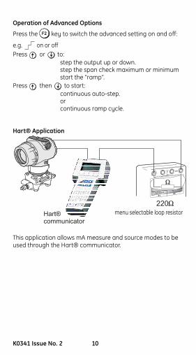
Operation of Advanced Options
Press the key to switch the advanced setting on and off:
e.g. on or offPress or to:
step the output up or down.step the span check maximum or minimumstart the “ramp”.
Press then to start:continuous auto-step.orcontinuous ramp cycle.
Hart® Application
This application allows mA measure and source modes to be used through the Hart® communicator.
Advanced%
+100.0%
mA
mA ( 24V )
COM
V
+24.000 mA
Hart®communicator
�
220�
menu selectable loop resistor
11 K0341 Issue No. 2
Maintenance• Return the loop calibrator to an authorised ATEX repair
centre for any repairs, it cannot be repaired on-site.
• To keep the loop calibrator accurate a calibration check should be carried out once per year.
Cleaning• Clean the loop calibrator leather case with a moist, lint-
free cloth and weak detergent.

K0341 Issue No. 2 12
Battery ReplacementWARNING: ONLY REPLACE BATTERIES IN A SAFE AREAOnly use the battery type listed on page two.Unscrew and remove the securing screw from the battery panel. Replace the batteries, check the polarity of the batteries. Refit and secure the battery panel.
13 K0341 Issue No. 2
Calibration InstructionsWARNING:
CALIBRATE UPS-III-IS LOOP CALIBRATORS IN A SAFE AREA.General
The instrument is supplied by the manufacturer, complete with calibration certificate(s). A calibration period of 12 months is recommended. The actual calibration interval depends on instrument usage and the total measurement uncertainty acceptable for the specified application.
The UPS-III-IS is a very precise measuring instrument and the test equipment and conditions of test must be suitable for the type of work. The calibration check and calibration adjustment should be carried out in a controlled environment by a calibration technician*.
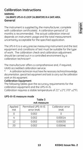
The manufacturer offers a comprehensive and, if required, UKAS accredited calibration service.* A calibration technician must have the necessary technical knowledge, documentation, special test equipment and tools to carry out the calibration work on this equipment.Calibration Equipment The following tables give the accuracy requirements for the calibration equipment and the UPS-III-IS.Calibration requires a stable temperature of 21° ±1°C (70° ±2°F).
UPS-III-IS measure modeTable 3
mA measureApplied
mAPermitted UPS-III-IS
error (mA)Calibrator error
(mA)0 0.002 0 4 0.002 0.00014
12 0.002 0.0003020 0.002 0.00046
K0341 Issue No. 2 14
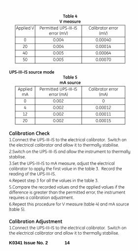
Table 4V measure
UPS-III-IS source modeTable 5
mA source
Calibration Check1.Connect the UPS-III-IS to the electrical calibrator. Switch on the electrical calibrator and allow it to thermally stabilise.2.Switch on the UPS-III-IS and allow the instrument to thermally stabilise.3.Set the UPS-III-IS to mA measure, adjust the electrical calibrator to apply the first value in the table 3. Record the reading of the UPS-III-IS.4.Repeat step 3 for all the values in the table 3.5.Compare the recorded values and the applied values if the difference is greater than the permitted error, the instrument requires a calibration adjustment.6.Repeat this procedure for V measure (table 4) and mA source (table 5).
Calibration Adjustment1.Connect the UPS-III-IS to the electrical calibrator. Switch on the electrical calibrator and allow it to thermally stabilise.
Applied V Permitted UPS-III-IS error (mV)
Calibrator error(mV)
0 0.004 0.00040 20 0.004 0.0001440 0.005 0.0006450 0.005 0.00070
Applied mA
Permitted UPS-III-IS error (mA)
Calibrator error(mA)
0 0.002 04 0.002 0.00012
12 0.002 0.0001120 0.002 0.00015
15 K0341 Issue No. 2
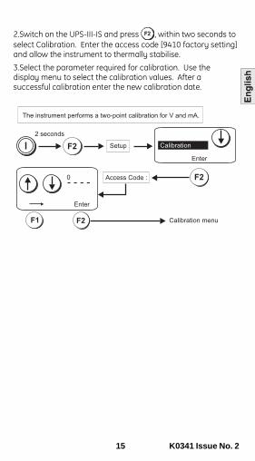
2.Switch on the UPS-III-IS and press , within two seconds to select Calibration. Enter the access code [9410 factory setting] and allow the instrument to thermally stabilise.
3.Select the parameter required for calibration. Use the display menu to select the calibration values. After a successful calibration enter the new calibration date.

K0341 Issue No. 2 16
F1
F1
Enter
F2
Enter
F2
20 mA ±0.004mA
mA out cal-low
Reading:
mA out cal-high
Reading:
+20.020
00.000
Enter
F2
mA out control
Check output
1.000
Enter
F2
Again
Check output
mA out control
20.000Again
Enter
F2
Calibration
Cal. dateV InputV Input
mA InputmA Output
A
Enter
F2
Calibration
Cal. dateV Input
mA InputmA Output
Correct PIN entered
mA
Advanced%
+100.0%00.000 mA
mA
mA ( 24V )
COM
V
1 mA ±0.002mA
mA
Advanced%
+100.0%
+01.000 mA
mA
mA ( 24V )
COM
V
20 mA ±1 mA
mA
Advanced%
+100.0%+20.020 mA
mA
mA ( 24V )
COM
V
mA
Advanced%
+100.0%+20.000 mA
mA
mA ( 24V )
COM
V

17 K0341 Issue No. 2
F1
Enter
F2
Enter
F2
Enter
F2
20 mA ±1 mA
Calibration
Cal. date
V Input
mA InputmA Output
mA input cal-low
Leave mA input open
-0.001
mA input cal-high
mA input ~ 20mA
00.000
+20.020
Enter
F2
mA input control
Check reading :
1.000Again
Enter
F2 B
A
Calibration
Cal. dateV InputV Input
mA InputmA Output
mAopen
Advanced%
+100.0%
Leave mA input open
mA
mA ( 24V )
COM
V
mAsource
Advanced%
+100.0%
+20.020 mA
mA
mA ( 24V )
COM
V
mAsource
1 mA ±0.002mA
Advanced%
+100.0%
+01.000 mA
mA
mA ( 24V )
COM
V

K0341 Issue No. 2 18
49 V ±1 V
V input cal-high
V input ~ 50V
00.000
+47.438
49 V ±1 V
V input control
Check reading:
49.000Again
B
CALIBRATION COMPLETEMORECALIBRATIONSELECTIONS
Enter
F2
Enter
F2
Enter
F2
Calibration
Cal. date
V InputV Input
mA InputmA Output
V input cal-low
Short V input.
-0.001
F1
Enter
F2
F1 F2
F2
Enter
Calibration
Cal. dateCal. dateV Input
mA InputmA Output
Quit
Cal. date: 01-MAR-2006
Enter
Day : 01
Enter
Calibration
Cal. dateCal. dateV Input
mA InputmA Output
Enter
Month : 03
Cal. date: 01-MAR-2006
F2
F2
F2
F2
Enter
Year : 2006
Cal. date: 01-MAR-2006
F1 F2
Calibration date
EnterAgain
Check date:
01 MAR 2006
V
source
Advanced%
+100.0%+49.000 V
Advanced%
+100.0%
Short V input
mA
mA ( 24V )
COM
V
mA
mA ( 24V )
COM
V
V
source
Advanced%
+100.0%
Vinput ~ 50V
+47.438
mA
mA ( 24V )
COM
V


