Issue: Oct 2011 / Ver 1.0 / Rev 0 Page | 1 Of 56 Proposal For “uPVC Windows” Indian Standard Windows & Doors Manufactured from Multi-chambered un-plasticized Poly Vinyl Chloride Profiles Released : 14 th October 2011 Version : 1.0 Revision : 1.0 Feb 1, 2012
Transcript
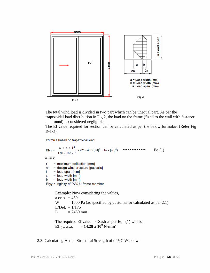
Issue: Oct 2011 / Ver 1.0 / Rev 0 P a g e | 1 Of 56
Issue: Oct 2011 / Ver 1.0 / Rev 0 P a g e | 2 Of 56
CONTENTS
Page no.
1. Foreword 3
2. Scope 3
3. Normative reference 3
4. Terminology 5
4.1 Profiles 5
4.2 Windows 6
5. Abbreviation of types of window and doors 7
5.1 Abbreviations for design and style 7
5.2 Opening representation on drawing 9
6. Function requirement of uPVC Window 9
7. Raw Materials 9
7.1 Profiles 9
7.2 Reinforcement 15
7.3 Gasket 16
7.4 Hardware 16
7.5 Glass 16
8. Welds & Mechanical Joints 16
9. Window Construction 17
9.1 Drainage & Pressure equalization 17
9.2 Glass Glazing 18
9.3 Glazing Bead 19
9.4 Installation packers 19
9.5 Location of Fixing points 20
9.6 Fixing / Filling material 20
10. Testing of Windows 20
10.1 Air permeability test 20
10.2 Water tightness under static pressure 21
10.3 Wind resistance test 21
11. Marking of windows 22
12. Annexure: A- N 23-55
Issue: Oct 2011 / Ver 1.0 / Rev 0 P a g e | 3 Of 56
1. FOREWORD
This is the first standard prepared to provide key parameters required for manufacturing and
testing of uPVC windows & doors.
This standard covers aspects relating to input material to uPVC windows, testing of
windows and its components, relevant process and standards.
The methods of tests are primarily based on ISO, BIS and ASTM standards.
2. Scope
The standard mentioned in this proposal specifies the requirements for the windows and
doors made out of multi chamber uPVC profile and its accessories.
The proposal includes the window requirements and test methods for windows.
3. NORMATIVE REFERENCE
This Indian Standard incorporates, by dated or undated reference, provisions from other
publications. These normative references are cited at the appropriate places in the text, and
the publications are listed hereafter. For dated references, subsequent amendments to or
revisions of any of these publications apply to this Indian standard only when incorporated
in it by amendment or revision. For undated references the latest edition of the publication
referred to applies (including amendments).
ISO 305:1990 Plastics Determination of thermal stability of poly (vinyl chloride), related chlorine-containing homopolymers and copolymers and their compounds -- Discoloration method
ISO 527 Method of testing plastics-Mechanical Properties Tensile strength, Elongation & elastic modulus
ISO 178 Plastics -Determination of flexural properties (ISO 178:1993)
ISO 179-2 Plastics- Determination of Charpy impact properties- Part 2: Instrumented impact test (ISO 179-2:1997)
ISO 306 Plastics-Thermoplastic materials- Determination of Vicat softening temperature (VST) (ISO 306:1994)
ISO 8256 Plastics-Determination of tensile impact strength (ISO 8256:1990, including technical
corrigendum 1:1991)
Issue: Oct 2011 / Ver 1.0 / Rev 0 P a g e | 4 Of 56
ISO 1163-2:1999 Plastics-Unplasticized polyvinyl chloride (uPVC) molding and extrusion materials Part 12: Preparation of test specimens and determination of properties (ISO 1163-2:1995)
ISO 4892-1:1999 Plastics- Methods of exposure to laboratory light sources -- Part 1: General guidance ISO 4892-2:2006 Plastics-Method of exposure to laboratory light source- Part 2: Xenon arc source
ISO 291:2005 Plastics -- Standard atmospheres for conditioning and testing
IS 4020 (PART-2) – 1994 Determination of squareness at welded joints of the profile.
IS 4020 (PART-7) – 1994
Determination deflection due to load applied on the edges. IS 4020 (PART-8) – 1994 Determination of shock resistance of fixings, fastenings and hangings in the window. IS 4020 (PART 11) – 1994 Determination of any deformation of parts, hindering the normal working of the shutter. IS 277:2003 Determination of the standard of galvanized steel sections used as reinforcement in UPVC profiles. ISO 9227:2006
Determination of salt spray test on reinforcement steel ISO 7619 -1: 2000 Determination of Shore hardness of EPDM gasket.
ISO 527-2:1993 Determination of tensile strength of EPDM gasket.
ISO 815-2:2008 Determination of compression of EPDM gasket
ISO 9227:2006 Determination of window fittings when subjected to salt spray test.
ISO 6613:1980 Testing of air permeability of windows.
ISO 15821: 2007 Testing of water tightness under dynamic pressure for doors and windows.
ISO 6612 - 1980 Determination of wind resistance in windows.
Issue: Oct 2011 / Ver 1.0 / Rev 0 P a g e | 5 Of 56
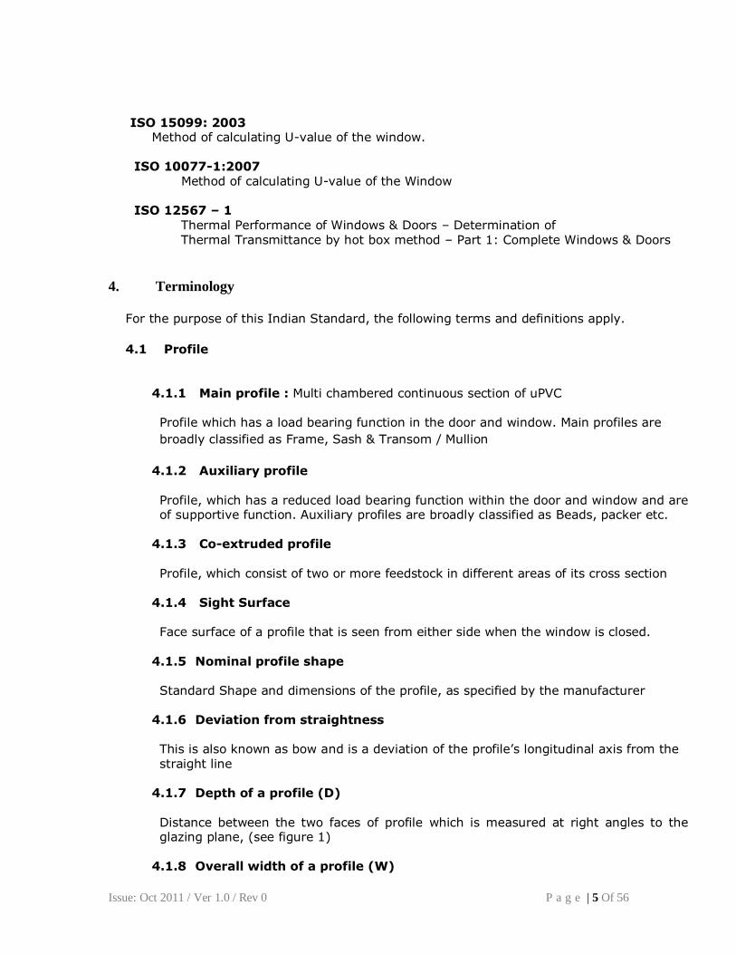
ISO 15099: 2003 Method of calculating U-value of the window.
ISO 10077-1:2007 Method of calculating U-value of the Window ISO 12567 – 1 Thermal Performance of Windows & Doors – Determination of Thermal Transmittance by hot box method – Part 1: Complete Windows & Doors
4. Terminology
For the purpose of this Indian Standard, the following terms and definitions apply.
4.1 Profile
4.1.1 Main profile : Multi chambered continuous section of uPVC
Profile which has a load bearing function in the door and window. Main profiles are
broadly classified as Frame, Sash & Transom / Mullion
4.1.2 Auxiliary profile Profile, which has a reduced load bearing function within the door and window and are of supportive function. Auxiliary profiles are broadly classified as Beads, packer etc.
4.1.3 Co-extruded profile
Profile, which consist of two or more feedstock in different areas of its cross section
4.1.4 Sight Surface
Face surface of a profile that is seen from either side when the window is closed.
4.1.5 Nominal profile shape
Standard Shape and dimensions of the profile, as specified by the manufacturer 4.1.6 Deviation from straightness
This is also known as bow and is a deviation of the profile’s longitudinal axis from the
straight line
4.1.7 Depth of a profile (D)
Distance between the two faces of profile which is measured at right angles to the glazing plane, (see figure 1)
4.1.8 Overall width of a profile (W)
Issue: Oct 2011 / Ver 1.0 / Rev 0 P a g e | 6 Of 56
Greatest distance, measured in the direction of the glazing plane and perpendicular to the longitudinal axis of the profile (see figure 1)
4.2 Windows
4.2.1 Casement Framed opening window that is hinged or pivoted.
4.2.2 Window Fastening Component that is used to secure a completed window assembly into the structure of a building.
4.2.3 Glazing gasket EPDM (or TPE) used between the glass and the frame and/or the glass and glazing bead.
4.2.4 Window Hardware Any fitting attached to the window, which is used to operate and/ or secure it.
4.2.5 Multi – Window (bay / coupled) Window incorporating more than one opening and/or fixed within one perimeter frame coupled with members to form single entity in straight or angled.
4.2.6 Frame It is the non-movable or fixed portion of the window attached to the wall and the sash is assembled to it.
4.2.7 Sash Opening part in the window / door.
4.2.8 Glazing Bead
Profile which holds the glass or other partition material (e.g. board) in door and window profile section
4.2.9 Transom / Mullion Is a profile used within the frame, vertically or horizontally in and / or frame / sash.
4.2.10 Switch barrier
Device that prevents a tilt and turn window from engaging in the tilt mode and the turn mode at the same time
D
W FIGURE 1 Sight Surface
Issue: Oct 2011 / Ver 1.0 / Rev 0 P a g e | 7 Of 56
4.2.11 Friction stays or Hinges Device which assembled in the windows / doors frame and sash, enables the
movement of sash in the window / door frame.
4.2.12 Weather pile strip Strip designed to reduce air infiltration and water penetration.
4.2.13 Reinforcement The GI steel section or other material placed inside or coextruded to provide strength
to the uPVC profile section. In case of steel section, the same should be placed in a separate chamber in the profile.
4.2.14 Wind load Peak wind pressure that can be expected on a surface of a building window or component. Relevant Standards applicable for the same should be referred.
4.2.15 Ventilation Device Ventilator other than opening light incorporated in a window or door
4.2.16 Water Penetration Continuous or repeated wetting of the internal surface of the test specimen or parts which are not designed to be wetted when water drains back to external surface.
4.2.17 Weather tightness Performance in respect of air permeability, water tightness and wind resistance
4.2.18 Design Height Max height of wall in which the window or door occurs
5. Abbreviations for types of windows and doors
Code Description
F Fixed
CW Casement window
SW Sliding Window
CD Casement Door
SD Sliding Door
5.1 Abbreviations for design/ style options
Code Description
TH Top hung HS Horizontal sliding
BH Bottom hung TT Tilt and turn
VP Vertical pivot TS Tilt and Slide
HP Horizontal pivot LS Lift and Slide
VS Vertical sliding SF Slide and Fold
Issue: Oct 2011 / Ver 1.0 / Rev 0 P a g e | 8 Of 56
F
Casement Window/ Door
(Outward open)
Fixed Window Sliding Window/ Door
Horizontal Pivot Top Hung
Tilt & Turn Bottom Hung
Lift Slide Door
Tilt Slide DoorSlide Fold Window/ Door
Note: All windows are viewed from inside
Figure 2 (Symbolic representation of windows)
Issue: Oct 2011 / Ver 1.0 / Rev 0 P a g e | 9 Of 56
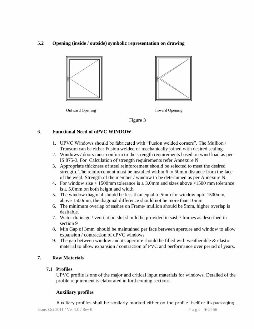
5.2 Opening (inside / outside) symbolic representation on drawing
Figure 3
6. Functional Need of uPVC WINDOW
1. UPVC Windows should be fabricated with “Fusion welded corners”. The Mullion /
Transom can be either Fusion welded or mechanically joined with desired sealing.
2. Windows / doors must conform to the strength requirements based on wind load as per
IS 875-3. For Calculation of strength requirements refer Annexure N
3. Appropriate thickness of steel reinforcement should be selected to meet the desired
strength. The reinforcement must be installed within 6 to 50mm distance from the face
of the weld. Strength of the member / window to be determined as per Annexure N.
4. For window size ≤ 1500mm tolerance is ± 3.0mm and sizes above ≥1500 mm tolerance
is ± 5.0mm on both height and width.
5. The window diagonal should be less than equal to 5mm for window upto 1500mm,
above 1500mm, the diagonal difference should not be more than 10mm
6. The minimum overlap of sashes on Frame/ mullion should be 5mm, higher overlap is
desirable.
7. Water drainage / ventilation slot should be provided in sash / frames as described in
section 9
8. Min Gap of 3mm should be maintained per face between aperture and window to allow
expansion / contraction of uPVC windows
9. The gap between window and its aperture should be filled with weatherable & elastic
material to allow expansion / contraction of PVC and performance over period of years.
7. Raw Materials
7.1 Profiles
UPVC profile is one of the major and critical input materials for windows. Detailed of the
profile requirement is elaborated in forthcoming sections.
Auxiliary profiles
Auxiliary profiles shall be similarly marked either on the profile itself or its packaging.
Outward Opening Inward Opening
Issue: Oct 2011 / Ver 1.0 / Rev 0 P a g e | 10 Of 56
The marking of auxiliary profile shall contain the following minimum information
the name or trade mark of the manufacturer
reference to this Indian standard production code sufficient to enable traceability
7.1.1 Material
Compound of uPVC in the form of granules or powder for the production of profiles for
the fabrication of windows and doors
a. Defined formulation
Stated formulation which is a controlled composition of polymer and its additives
b. Virgin Material
Material of defined formulation in granular or powder form, which has not been
processed, earlier other than required for its manufacture is virgin material. No re-
processable or recyclable material has been added.
c. Recyclable material
Own recyclable / re-processable material
Material of defined formulation free of contamination and degradation, made from UPVC
profiles including off cuts from own fabricator, which is re-processable in the same
factory in which it was extruded. This can be used in the extrusion process with or without
additional compounding to adjust the specified properties of material, as stated in
annexure A.
External recyclable /re-processable material
Material free of contamination and degradation, made from unused uPVC window
profiles, including off cuts from other fabricators, which has been originally processed by
a manufacturer other than that carrying out reprocessing. This material shall be used in
core of a profile. Any surface or parts of surfaces which may be visible after installation of
window, fabricated from the profiles, shall be completely covered by co extrusion by
virgin material. The thickness of co extruded outer surface layer shall not be less than 0.5
mm.
This standard does not allow using external re-processable uPVC material, not made for
uPVC window & door application.
d. Composition
Profile shall be made from material/additives constituting of un-plasticized polyvinyl
chloride (uPVC).
e. Physical Properties
Issue: Oct 2011 / Ver 1.0 / Rev 0 P a g e | 11 Of 56
Un-weathered uPVC material from which profiles are made shall conform to the
requirements in Table 1 when tested in accordance with the test method specified.
Tests shall be carried out on sample cut from the visible surfaces of extruded profiles
except for the apparent modulus of elasticity test for which samples shall be tested on
pressed plaques prepared from milled sheet under the conditions specified in ISO 1163-2
Table 1 – Physical Properties of uPVC Compound
S. No.
Properties
Test Method Permissible Value
i) Vicat Softening point
ISO 306 ≥75 ° C
ii) Apparent modulus of elasticity ISO 178
≥ 2200MPa
iii) Color Fastness
ISO 4892-2 DE ≤ 5
iv) Heat Stability
ISO 182
≥30 min
v) Charpy Impact strength (milled sheet)
ISO 179
≥10 kJ/m²
vi) Retention of Charpy impact strength after artificial aging
ISO 179
≥60 % of original value
7.1.2 Requirements of profile
A. Color
This standard applies to profiles in the color range of white to cream. Annexure C defines
the applicable color range and permissible tolerance.
B. Appearance The appearance of the profile shall be the same and uniform on any surfaces and/or parts of surfaces which may be visible after installation of the window fabricated from the profile, when viewed in accordance with Annexure A
The surface of the profiles shall be flat, smooth and free from pitting, impurities, cavities and other surface defects when viewed in accordance with Annexure A. The edges of the profile shall be clean and free of burr. Note1: Further arrangements with respect to appearance such as color range and tolerance on the standard color should be made between the customer and the manufacturer and are not part of this standard (see Annexure C).
Note 2: Extrusion lines, pitting, impurities, cavities & other surface defects caused by the process are admissible so long as they are not visually intrusive from 1m.
C. Dimensions and tolerances
C.1 Shape
Issue: Oct 2011 / Ver 1.0 / Rev 0 P a g e | 12 Of 56
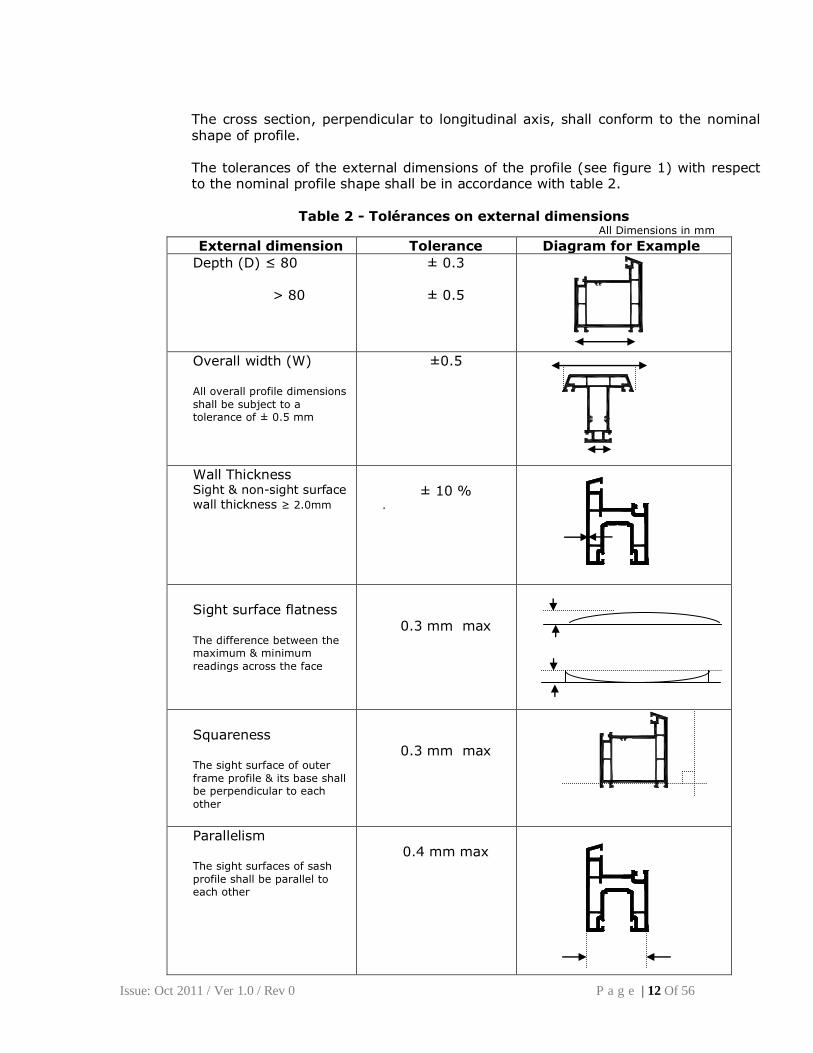
The cross section, perpendicular to longitudinal axis, shall conform to the nominal shape of profile.
The tolerances of the external dimensions of the profile (see figure 1) with respect to the nominal profile shape shall be in accordance with table 2.
Sight surface flatness The difference between the maximum & minimum
readings across the face
0.3 mm max
Squareness The sight surface of outer
frame profile & its base shall be perpendicular to each
other
0.3 mm max
Parallelism The sight surfaces of sash
profile shall be parallel to each other
0.4 mm max
Issue: Oct 2011 / Ver 1.0 / Rev 0 P a g e | 13 Of 56
The determinations of external dimensions is in accordance with Annexure A
C.2 Thickness of profile
Wall thickness of sight surfaces shall be uniform and determined in accordance with Annexure A. The min wall thickness of sight surface should be 2.0 ± 10%
C.3 Other dimensions
The dimensions of profile other than the thickness of external walls as well as their tolerances shall be specified by the manufacturer.
C.4 Straightness of profiles
For main profiles like outer frame, transom and sash, the deviation from straightness measured in accordance with Annexure A shall not be > 1 mm for a
length of 1m (table 2) For auxiliary profiles like, glazing beads, decorative profiles, parkers etc., the deviation from straightness measured in accordance with Annexure A shall be specified by the manufacturer.
D. Mass of profiles
When measured in accordance with Annexure A the mass per m length of profile shall not be < 95 % of the nominal mass per m length specified by supplier.
E. Heat reversion
E.1 Main profile
When tested in accordance with Annexure I for each test specimen, the heat reversion of the two largest opposing sight surfaces shall not be > 2.0 % The difference in heat reversion for each test specimen between these sight surfaces shall not be >0.4 %
E.2 Auxiliary profiles
When tested in accordance with Annexure I, the heat reversion for each test specimen shall not be > 3.0 %
F. Resistance to impact of main profiles by falling mass
When tested in accordance with Annex E, there shall be no crack of the surface of test specimen when subjected to free wall of mass from height of 1m. No more than one test specimen shall show rupture in the wall. For co extruded profiles the de-lamination of the co extruded layer is also considered as failure.
Issue: Oct 2011 / Ver 1.0 / Rev 0 P a g e | 14 Of 56
G. Heat Aging Behavior at 150°C
When tested in accordance with Annex F, the profiles shall show no defects as blisters,
cracks, surface peel off. For co extruded profiles the de-lamination of the co extruded layer is also considered as failure.
H. Resistance to weathering
H.1 Exposure procedure
Test specimen (refer ISO 4892-1) taken from sight surfaces of main profiles shall be exposed accordance with ISO 4892-2, Method A, for a time period of 6000 hr. Calculation of exposure hours representing five years outdoor weathering is given in Annexure D. Note: For quality control purpose the time period can be decreased to representing two years out door exposure.
H.2 Impact strength after artificial weathering
After exposure in accordance with H.1 the reduction in impact strength expressed as a percentage of the impact strength of the unexposed test specimen and the exposed test specimen shall not be > 40%
The determination of the impact strength is in accordance with ISO 179. Note: The value of 40 % is tentative and subjected to the results of current research.
H.3 Color fastness
After exposure in accordance with H.1, the change in color between the unexposed and exposed test specimens expressed in Δ E* shall not be > 5 and Δ b* not > 3. Note: The visual change in color can be determined using the methods specified in ISO 7724-1, ISO 7724-2, and ISO 7724-3
I. Weld ability
For the determination of the Weldability of profiles, welded corners are tested in accordance with Annex G. The calculated mean stress at maximum load of each corner, σ t or σ c, shall not be < 25 N/mm² for the tensile bending test and not be < 30 N/mm² for the compression bending strength. σ t = the failure stress by tensile bending (N/mm²)
σ c = the failure stress by compression bending (N/mm²) The sample subjected to weld test shall not be finished by grooving, knifing etc, except for the outside edge of 90° angle, which shall be cleaned to permit the sample to sit fully onto the support.
Issue: Oct 2011 / Ver 1.0 / Rev 0 P a g e | 15 Of 56
J. Marking
Main profiles
Main profiles shall be legibly and visibly marked in an unobtrusive position not visible when the window is closed at least once in every 1 m along the length of the profile.
The marking of the main profiles shall contain the following minimum information
the name or trade mark of the manufacturer reference to this Indian standard Production code sufficient to enable traceability (e.g. Date, machine, and/or shift
no.) Example ABC LTD –IS xxxx- Date-M/C-Shift
Optional additional information contained within the mark may include:
Profile type/code
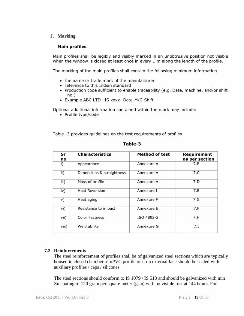
Table -3 provides guidelines on the test requirements of profiles
Table-3
Sr no
Characteristics Method of test Requirement as per section
i) Appearance
Annexure A 7.B
ii) Dimensions & straightness
Annexure A 7.C
iii) Mass of profile
Annexure A 7.D
iv) Heat Reversion
Annexure I 7.E
v) Heat aging
Annexure F 7.G
vi) Resistance to impact
Annexure E 7.F
vii) Color Fastness
ISO 4892-2 7.H
viii) Weld ability
Annexure G 7.I
7.2 Reinforcements
The steel reinforcement of profiles shall be of galvanized steel sections which are typically
housed in closed chamber of uPVC profile or if on external face should be sealed with
auxiliary profiles / caps / silicones
The steel sections should conform to IS 1079 / IS 513 and should be galvanized with min
Zn coating of 120 gram per square meter (gsm) with no visible rust at 144 hours. For
Issue: Oct 2011 / Ver 1.0 / Rev 0 P a g e | 16 Of 56
external usage of reinforcement (ex – couplers), it is recommended to have 275gsm Zn
coating.
The steel section should be used in the frame and / or sash to meet the desired
specifications of window performance.
The steel section thickness should be based on the strength required as per the wind load
specification of the window. For steel thickness & strength calculation of section refer to
Annexure-N
7.3 Glazing Gaskets & Weather strip
The gaskets / weather strip shall be of EPDM/ TPE or any equivalent material which
meets the following properties
a) Shore A Hardness of the material should be 60±10° A; (ref ISO 7619)
b) Ozone resistance: No visible cracks; (ref ISO 1431)
c) Compression set: should not exceed 50% ; (ref ISO 815)
d) Aging test: The properties after aging should be (ISO 188)
i. Hardness +10 / -5
ii. Tensile Strength not to exceed drop beyond 25%
iii. Elongation not to exceed drop beyond 25%
7.4 Window Hardware’s
The window hardware including the fastenings shall be tested in accordance with ISO
9227: 2006 for corrosion resistance when subjected to neutral salt spray test.
The performance parameters like load bearing, MOC, endurance should be specified by
the supplier or mutually agreed between the two parties.
Note1: It should be noted that there is no direct correlation between a given no. of hours salt spray testing and real time natural environment exposure.
Note2: In coastal or industrial environment, the hardware performance should be specified.
7.5 Glass
Glass thickness should meet the wind load requirements as per IS 875-3. The glass should
be of at least the 4mm thickness.
Hermetically sealed flat double glazing units can be provided by the manufacturers of
windows with requisite glass beading.
8. Welds & Mechanical Joints
The uPVC window welds should meet the norms as specified in section 7.1.2 (I).
Issue: Oct 2011 / Ver 1.0 / Rev 0 P a g e | 17 Of 56
Mechanical joints can be made with adequate sealing to prevent any water / air ingress in
the reinforcement chambers.
Water should not penetrate through the joints into the reinforcement chambers other than
those designed to allow water ingress
9. Window Construction & Installation
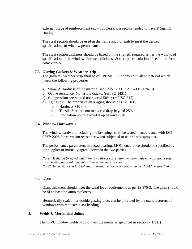
9.1 Drainage & pressure equalization holes:
Ventilation / Drainage holes / slots is to created on Frames / Sash / Transom / Mullions to drain
entrapped water / moisture / hot air from the system.
The no. of holes / slots should be in line with profile manufacturer’s recommendation. Typical drainage
is recommended to be slots of min 5 x 20mm
The holes / slots should not puncture the reinforcement chamber
The holes / slots are offset between the inner & outer wall to prevent back flow
Holes / slots to be created for ventilation / pressure equalization in sash(s) / frame(s) for prevention of
deformation of profiles due to heat
entrapment.
Typical drainage schematic
Issue: Oct 2011 / Ver 1.0 / Rev 0 P a g e | 18 Of 56
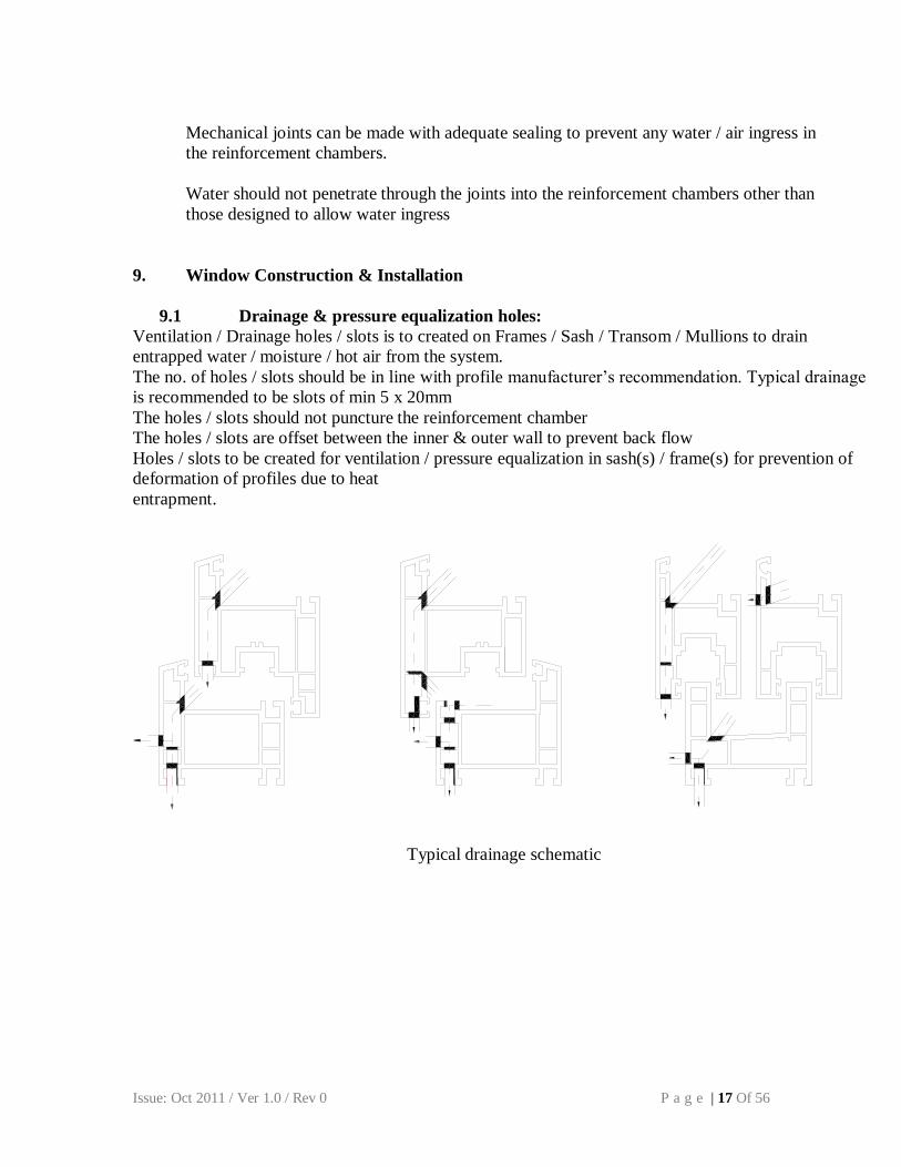
9.2 Glass Glazing:
Glazing Support – are supports which installed on the frame / sash to take / distribute the load of the
glass. These are installed first to place the glass in the frame / sash.
Glazing Spacers – are packers which support the glass in the frame / sash and installed after the glazing
support are installed.
The Glazing spacers / support must not block the drainage slots.
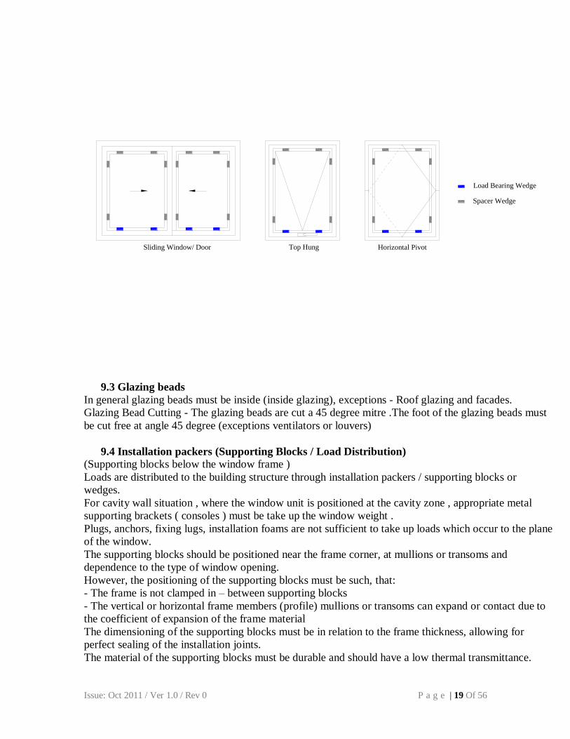
The glass packer position should be adopted basis type of window illustrated below.
Typical Glazing Spacer:
The glazing support position for different styles of windows:
F
Fixed WindowTilt & Turn Bottom Hung Side Hung
Issue: Oct 2011 / Ver 1.0 / Rev 0 P a g e | 19 Of 56
Sliding Window/ Door Top Hung Horizontal Pivot
Load Bearing Wedge
Spacer Wedge
9.3 Glazing beads
In general glazing beads must be inside (inside glazing), exceptions - Roof glazing and facades.
Glazing Bead Cutting - The glazing beads are cut a 45 degree mitre .The foot of the glazing beads must
be cut free at angle 45 degree (exceptions ventilators or louvers)
Loads are distributed to the building structure through installation packers / supporting blocks or
wedges.
For cavity wall situation , where the window unit is positioned at the cavity zone , appropriate metal
supporting brackets ( consoles ) must be take up the window weight .
Plugs, anchors, fixing lugs, installation foams are not sufficient to take up loads which occur to the plane
of the window.
The supporting blocks should be positioned near the frame corner, at mullions or transoms and
dependence to the type of window opening.
However, the positioning of the supporting blocks must be such, that:
- The frame is not clamped in – between supporting blocks
- The vertical or horizontal frame members (profile) mullions or transoms can expand or contact due to
the coefficient of expansion of the frame material
The dimensioning of the supporting blocks must be in relation to the frame thickness, allowing for
perfect sealing of the installation joints.
The material of the supporting blocks must be durable and should have a low thermal transmittance.
Issue: Oct 2011 / Ver 1.0 / Rev 0 P a g e | 20 Of 56
9.5 Location of fixing points
9.6 Fixing Material
The fixing material should be selected in a way which does not hinder expansion or contraction
of the window at the building joint at the same time secures the window with the aperture to
sustain the max wind load. Fixing material can be anchor bolts, installation screws, fixing clips,
sub- frames etc.
10. TESTING OF WINDOWS
The window subjected to the testing should adopt the following Sequence of Test.
a) Air Permeability
b) Water tightness
c) Resistance to wind – deflection measurement at Pressure P1 (=P3/1.5)
d) Resistance to wind – pulsating test to P2 pressure (=0.5P1)
e) Resistance to wind – Safety test to pressure P3 (the max wind load as per IS 875)
10.1 Air Permeability Test
It is to let air pass when it is subjected to differential pressures under closed
condition of the window.
The method to be used for the air permeability testing of windows to be fitted in
exterior walls and supplied in the form of completely assembled and finished units
as per the test procedure given in the Annexure M
Classification for air permeability
Class 0 1 2 3 4
Max. test
pressure Pa
No
test
150 300 600 600
Reference air
permeability at
100 Pa (m3/
h.m2)
NA 50 27 9 3
“A” is the distance between two neighboring fixing
points and shall not exceed 700mm “E” is the distance between the fixing points to the end of the profile joint and
recommended between 100 -
150mm
Issue: Oct 2011 / Ver 1.0 / Rev 0 P a g e | 21 Of 56
10.2 Water tightness under static pressure (water flow rate 3L/sq.m/min ± 10%)
Water tightness is the ability of the window to resist water leakage into the building.
ISO 15821: 2007 defines the test method for determining the water tightness under
dynamic pressure of doors and windows assembled for normal use and installed as in
practice. The test procedure is given in the Annexure – K. The classifications of the
windows tested as per ISO 15821 can be classified as per table below. The window
is said to of the class when water is seen at during the testing at the test value
Classification for Water Tightness
Class 0 1 2 3 4 5
A B A B A B A B A X
Test
Pressure
Pa
- 0 50 100 150 200 250 300 450 600 >600
10.3 Wind Resistance Test
This test is to determine the resistance to wind load for completely assembled
windows and doors when subjected to positive and negative test pressures.
The test pressures used for the testing are defined as,
i. P1 applied to measure deflections of parts of the test specimen
ii. P2 pulsating pressure applied for 50 cycles to assess performance under
repeated wind load
iii. P3 applied to assess the safety of the test specimen under extreme conditions.
The values of P1, P2 P3 are related as follows:
P3 = max wind load as per IS 875
P3 = 1.5P1
P2 = 0.5P1
Following 3 sets of test pressures are to carried out in the sequence defined
a) Deflection measurement under wind load Pressure P1 is conducted till deflection
achieved is 15mm or (i) L/125 for single glass (ii) L/175 for double glass,
whichever lower is achieved.
b) Pulsating test to P2 pressure. After completion of test, test piece is opened and
closed and any deformation / damage / malfunctions observed are recorded
c) Safety test to pressure P3. All deformation, damage and malfunctions that have
occurred are to be recorded in the report.
Classification for Window Load
Class 0 1 2 3 4 5 WR
Test Pressure P1
(Pa)
No
test
500 1000 1500 2000 2500 >2500
For simulating above tests, test procedure as per ISO 6612-1980 to be adopted.
Issue: Oct 2011 / Ver 1.0 / Rev 0 P a g e | 22 Of 56
11. Window Testing Report
The window tested as per this standard shall have following
11.1 Reference to this Indian standard
11.2 Name of the test laboratory 11.3 The name or trade mark of the manufacturer to identify the manufacturer 11.4 Date of manufacture
11.5 Date of the test 11.6 the apparatus and its calibration 11.7 All relevant details concerning the dimensions of the specimen, its material, design,
construction and manufacturer & manufacturing location and its surface finish and fittings;
11.8 Drawings of details of the specimen including cross section to a scale of 1:2 or
larger 11.9 number of samples 11.10 purpose of the test
11.11 characteristics to be determined and clear identification of which samples to be used
for the required characteristic(s), wherever necessary
11.12 signature of the sampler and the manufacturer if necessary
11.13 Test procedures, including storage and conditioning prior to test, and mounting the
test specimen ready for test
11.14 results of the test including analysis if relevant
11.15 place, date and authorized signature
Issue: Oct 2011 / Ver 1.0 / Rev 0 P a g e | 23 Of 56
Annexure - A Test Methods for uPVC Profiles
A.1 Determination of the appearance
The appearance is determined by viewing by normal or corrected vision at a range of 1m, at 45° north sky light.
A.2 Determination of dimensions
Measuring devices The measuring devices for the determination of the external dimensions and the wall thickness shall have an accuracy of 0.05 mm and for the deviation from the straightness shall have an accuracy of 0.1 mm
Test specimen For the determination of the deviation from straightness the length of the profile to be tested shall be 1000 ±5mm & for dimension measurement sample size shall be 300 ± 5 mm. In case of dimension measurement on optical instruments, suitable sample size shall be taken for measurement of dimension.
Conditioning Condition the test specimen at 27± 2°C for at least 1 hour prior to testing
Procedure Dimensions and wall thicknesses Dimensions and wall thicknesses shall be measured with precision equipments (e.g. Vernier Caliper, Projector, Scanner) having minimum accuracy of 0.05 mm as per standard operating procedure of the equipment.
Deviation from straightness Put the test specimen on flat surface (e.g. Surface table). Measure the gap(s) between the profile and the flat base with an appropriate measuring device (e.g. Distance gauges, filler gauge).Rotate the sample in 90 ° and again check the gap(s). Report the maximum gap observed between profile and flat surface.
A.3 Determination of the profile mass
Apparatus Balance with accuracy of 1 gm Use Measuring device with an accuracy of 0.5 mm for the determination of the profile length. Test specimen
The length of the profile to be tested shall be 200 mm to 300 mm Conditioning Condition the profiles before measuring at 27 ± 2 °C for at least 1 hour. Procedure
Measure the length of the test specimen to 1mm, weigh the test specimen to 1 gm. Determine the mass per length expressed in Kilogram per meter (Kg/m).
Issue: Oct 2011 / Ver 1.0 / Rev 0 P a g e | 24 Of 56
Annexure B Material characteristics- Sample preparation and requirements
1) Scope It covers sample preparation from uPVC profiles or from granules or powder for the determination of the characteristics and the requirements for those characteristics.
2) Terminology
Material: Compound mix with PVC and suitable additive to facilitate processing and to give the desired properties to end product.
3) Material properties
B.3.1 Vicat softening temperature
When tested in accordance with ISO 306 using method B with temperature rate of 50 ± 5 °C /h the Vicat Softening Temperature (VST) shall not be< 75 °C
For non co extruded profiles the test specimens shall be taken directly from the profiles or from pressed plaques
For Co extruded profiles the test specimens shall be taken directly from pressed plaques made from materials separately
In case of dispute the test on pressed plaques is the reference method.
B.3.2 Charpy Impact strength
When tested in accordance with ISO 179-2 at 27± 2°C with method designation 1eA the Charpy impact strength shall not be <10 KJ/m²
For non co extruded profiles the test specimens shall be taken from pressed plaques.
For co extruded profiles the test specimens shall be taken from pressed plaques made from both materials separately. In case of dispute the test on pressed plaques is the reference method.
B.3.3 Flexural modulus of elasticity
When tested at 27 ± 2 °C in accordance with ISO 178 the flexural modulus of elasticity (Eb) shall not be <2200 N/mm²
For non co extruded profiles the test specimens shall be taken directly from the profiles or from the pressed plaques.
For co extruded profiles the test specimens shall be taken from pressed plaques made from both materials separately. In case of dispute the test on pressed plaques is the reference
method.
Issue: Oct 2011 / Ver 1.0 / Rev 0 P a g e | 25 Of 56
B.3.4 Test specimen The test specimens for the determination of the material characteristics according A.3 shall
be taken either from profiles or from pressed plaques.
B.3.5 Preparation of pressed plaques The preparation of the pressed plaques shall be in accordance with the procedure given in clause 3 of ISO 1163-2:1999 and with the following
the material used shall be shredded extruded uPVC profiles, granules or powder materials
the differential speed between the two rolls of mixing mill shall be within the range 1:1.4 to 1:1.1
the pressed plaque shall have a thickness of 4± 0.2 mm the cooling of the plaque given in accordance 3.3.3 of ISO 1163-2:1999 shall be at
nominal rate 15 K/min
B.3.6 Test report
The test report shall include the following information;
reference to this annex details of the test specimen Standard for the Charpy impact strength values obtained
Issue: Oct 2011 / Ver 1.0 / Rev 0 P a g e | 26 Of 56
Annexure C Color range & Permissible tolerance
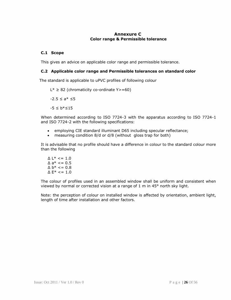
C.1 Scope This gives an advice on applicable color range and permissible tolerance. C.2 Applicable color range and Permissible tolerances on standard color
The standard is applicable to uPVC profiles of following colour
L* ≥ 82 (chromaticity co-ordinate Y>=60)
-2.5 ≤ a* ≤5
-5 ≤ b*≤15
When determined according to ISO 7724-3 with the apparatus according to ISO 7724-1 and ISO 7724-2 with the following specifications:
employing CIE standard illuminant D65 including specular reflectance; measuring condition 8/d or d/8 (without gloss trap for both)
It is advisable that no profile should have a difference in colour to the standard colour more than the following
Δ L* <= 1.0 Δ a* <= 0.5 Δ b* <= 0.8 Δ E* <= 1.0
The colour of profiles used in an assembled window shall be uniform and consistent when viewed by normal or corrected vision at a range of 1 m in 45° north sky light. Note: the perception of colour on installed window is affected by orientation, ambient light, length of time after installation and other factors.
Issue: Oct 2011 / Ver 1.0 / Rev 0 P a g e | 27 Of 56
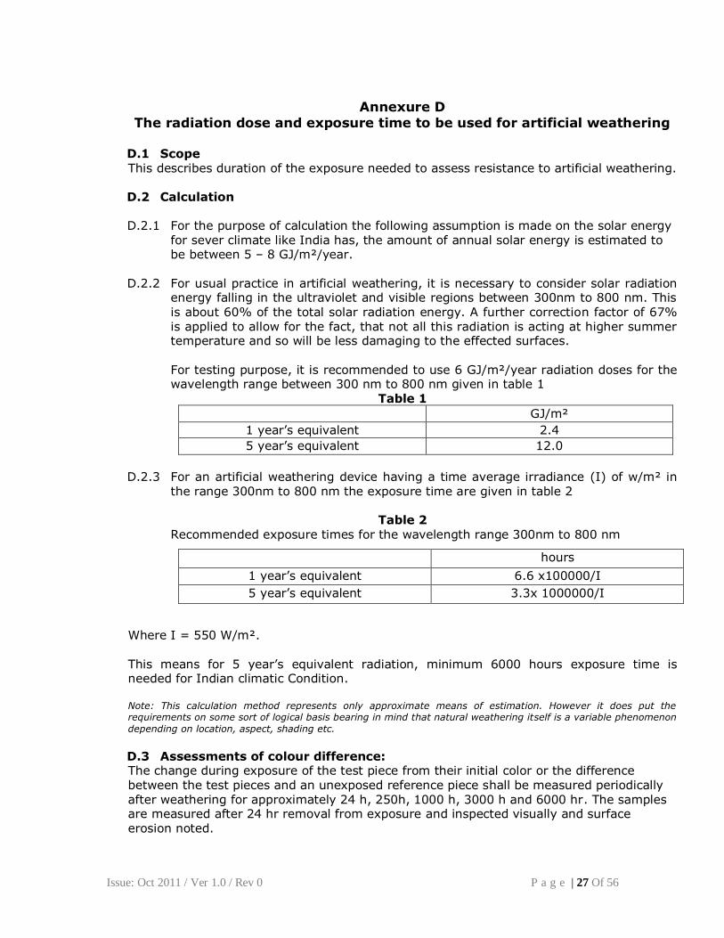
Annexure D
The radiation dose and exposure time to be used for artificial weathering D.1 Scope This describes duration of the exposure needed to assess resistance to artificial weathering. D.2 Calculation D.2.1 For the purpose of calculation the following assumption is made on the solar energy
for sever climate like India has, the amount of annual solar energy is estimated to be between 5 – 8 GJ/m²/year.
D.2.2 For usual practice in artificial weathering, it is necessary to consider solar radiation
energy falling in the ultraviolet and visible regions between 300nm to 800 nm. This is about 60% of the total solar radiation energy. A further correction factor of 67% is applied to allow for the fact, that not all this radiation is acting at higher summer temperature and so will be less damaging to the effected surfaces.
For testing purpose, it is recommended to use 6 GJ/m²/year radiation doses for the wavelength range between 300 nm to 800 nm given in table 1
Table 1
GJ/m²
1 year’s equivalent 2.4
5 year’s equivalent 12.0
D.2.3 For an artificial weathering device having a time average irradiance (I) of w/m² in
the range 300nm to 800 nm the exposure time are given in table 2
Table 2 Recommended exposure times for the wavelength range 300nm to 800 nm
Where I = 550 W/m².
This means for 5 year’s equivalent radiation, minimum 6000 hours exposure time is needed for Indian climatic Condition.
Note: This calculation method represents only approximate means of estimation. However it does put the requirements on some sort of logical basis bearing in mind that natural weathering itself is a variable phenomenon
depending on location, aspect, shading etc.
D.3 Assessments of colour difference: The change during exposure of the test piece from their initial color or the difference between the test pieces and an unexposed reference piece shall be measured periodically after weathering for approximately 24 h, 250h, 1000 h, 3000 h and 6000 hr. The samples are measured after 24 hr removal from exposure and inspected visually and surface erosion noted.
hours
1 year’s equivalent 6.6 x100000/I
5 year’s equivalent 3.3x 1000000/I
Issue: Oct 2011 / Ver 1.0 / Rev 0 P a g e | 28 Of 56
Annexure E Resistance to impact of main profiles by falling mass
E.1 Scope
This standard specifies a method for the determination of the resistance to impact by a falling mass at -10 °C (minus ten degree Celsius) of Unplasticized poly vinyl chloride (uPVC) main profiles for the fabrication of windows and doors for the assessment of the
extrusion.
E.2 Principle Test pieces cut from length of main profiles are subject to blow from a mass falling from a known height on the sight surface at a mid way between two supporting webs at a fixed temperature.
After testing the profiles are examined visually for failures.
E.3 Definitions For the purpose of this Indian Standards following definitions apply:
E.4.1 main profiles
Profile having load bearing function in the door and window. Main profiles are broadly classified as follows;
Outer Frame: Profile used to make door and window and which is fixed to the wall / structure. Sash: profile used to make openable panel Transom: profile used within the frame vertically or horizontally
E.4.2 sight surface
A face surface of a profile that is exposed to view from either side , when the window or door is closed.
E.4.3 Web
A membrane connecting two walls of a profile.
E.4 Apparatus
An impact testing machine incorporating the following basic components (see figure 1) shall be used: E.4.1 main frames, rigidly fixed in the vertical position E.4.2 guide rails, fixed to main frame to accommodate the falling mass and allowing
it to fall freely in the vertical plane E.4.3 Test piece support, consisting of a rounded off support With a distance
between (200 ± 1) mm. The support shall be made from Steel rigidly fixed in a solid foundation or on a table with a mass of more than 50 kg
E.4.4 release mechanism, such that the falling mass can fall through a height which can he adjusted up to (1500 +100 / -0) mm, measured from the top surface of the test piece to be tested;
Issue: Oct 2011 / Ver 1.0 / Rev 0 P a g e | 29 Of 56
E.4.5 Falling mass, of (1000±5) gm, this has a hemispherical striking surface of (25 ±0.5) mm radius. The striking surface shall be free from all imperfections.
E.5 Test pieces Ten test pieces, each of length of 300 mm shall be taken from a main profile.
E.6 Conditioning
The test pieces shall be conditioned at a temperature of -10 + 0/-2 °C for at least 1 hr before testing. Each test piece shall be tested within 10 Seconds of removal from the conditioning chamber.
E.7 Procedure The test shall be executed on sight surface of the main profile (preferably on the sight surface which is designed to be exposed to the weather). Drop the falling mass from a given height as required in the product standard at a point
mid way between two supporting webs. Note 1: wherever it is impracticable for the mass to hit the profile in accordance with 7.2 due to its geometry other impact position for the falling mass should be agreed upon between the profile manufacturer and testing laboratory.
Figure 1 – Impact Test Apparatus
Issue: Oct 2011 / Ver 1.0 / Rev 0 P a g e | 30 Of 56
Annexure F Heat Aging Behavior at 150°C
F.1 Scope
This standard specifies two methods for the determination of the effect of heat on unplasticized poly vinyl chloride (uPVC) profiles for the fabrication of windows and doors. The oven method is considered as the reference method.
F.2 Principle A test piece of a specified length of profile is maintained in an oven or liquid bath at 150 °C for 30 min. and is inspected visually on the inside, outside and the cross section of the wall for defects after heating.
F.3 F.3 Definition For the purpose of this Indian standard the following definition applies Defect: The visual appearance of blisters, cavities, or crack on any of the surfaces (inner or
outer) of the profile and of any delamination in the cross section.
F.4 Apparatus
F.4.1 Ventilated oven, thermostatically controlled, with air circulation, in which the test pieces can e exposed to a temp. of 150 °C. The oven shall be equipped with a thermo stat capable of maintaining the temperature at 150 ± 2 °C. The capacity of the oven shall be such that, after insertion of the test piece, the test temp. is regained with in 15 min.
F.4.2 Liquid bath, thermostatically controlled, in which the test pieces can be exposed to a
temp. of 150 °C. The capacity of the bath shall be such that after insertion of the test piece, the test temp. is regained with in 5 min. The liquid to be used shall be glycerin or an aromatic free hydro-carbon. This liquid shall be free of substances which may affect the properties of uPVC
F.4.3 Thermometer, graduated in 0.5 °C
F.5 Test Piece
The test piece shall be as follows: F.5.1 for testing in oven, a minimum length of 200 mm profile F.5.2 for testing in liquid bath, a minimum length of 300 mm of profile
F.6 Test Procedure F.6.1 Oven method
a. Set the oven temp. to 150 °C
b. When the oven has reached 150 °C, place the test piece horizontally in oven.
Issue: Oct 2011 / Ver 1.0 / Rev 0 P a g e | 31 Of 56
c. Maintain the test piece in the oven for 30 + 3 / -0 min, measuring
from the time when the oven temp has returned to 150 °C
d. Remove the test piece from the oven, taking care not to distort or
otherwise damage it
e. Allow the test piece to cool in air. When the test piece is cool enough for handling, examine it for defects.
F.6.2 Liquid bath method
a. Set the liquid bath temperature to 150 °C
b. When the liquid bath has reached 150 °C, hang the test piece vertically in the test liquid, so that the upper part does not protrude more than 100 mm out of the fluid. The means of suspending a test piece shall be such that it does not
touch either the floor or wall of the bath.
c. Keep the test pieces in the liquid bath for 30 +3/-0 min. measuring from the time when the liquid bath temp. has returned to 150 °C
d. Remove the test piece from the bath, taking care not to distort or otherwise
damage it.
e. Allow the test piece to cool in air. When the test piece is cool enough for handling examine it for defects.
F.7 Expression of results
The nature and the location of any defects shall be noted
F.8 Test report
The test report shall include the following information:
a. reference to this Indian Standard; b. the test laboratory; c. full identification of profile; d. the date of testing e. the apparatus used and for the liquid bath method, the type of liquid f. the result of the examination of the test piece; g. all operating details not specified in this Indian standard, as well as any
incidents likely to have influence the results
When tested with surface covered profiles shall show no bubbles between the acrylic layer and the foil of more than 1 mm, cracks, surface irregularities or delamitation. Note: There is no requirement for the flexible element of rigid and flexible co-extrusion. An increase
in gloss does not constitute failure
Issue: Oct 2011 / Ver 1.0 / Rev 0 P a g e | 32 Of 56
Annexure G Determination of the strength of welded corners and T joints
G.1 Scope This annexure specifies two test methods for the measurement of the failure load of welded
corners and T joints made from unplasticized poly vinyl chloride (uPVC) profile for the fabrication of windows and doors.
G.2 Definitions Failure load: That load at which yield occurs or if yield does not occur, the load at which the test piece breaks.
G.3 Principle Welded corners and T joints made from unplasticized poly vinyl chloride (uPVC) profiles are subjected to a tensile bending or compression bending test at specified temperature and test speed. The failure load is recorded and the failure stress is calculated.
G.4 Apparatus
G.5.1 Tensile or compression testing machine with the following specifications;
a. measuring range of load :2kN to 20 kN; b. load indication with zero point setting and peak recording c. measurement accuracy:±3% d. test speed: 50 ± 5 mm/min
G.5.2 Test arrangement
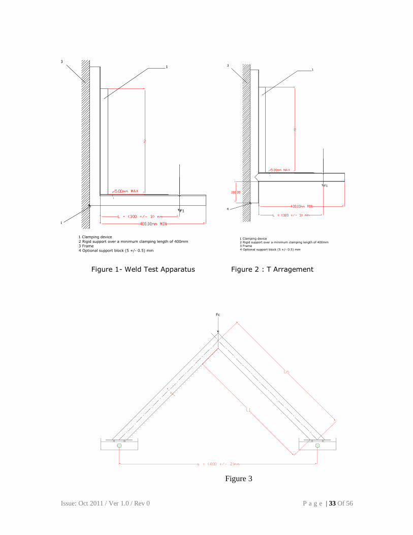
a. Corner weld sample for tensile bending test (see figure 1) b. T joint weld samples for tensile bending test (see figure 2)
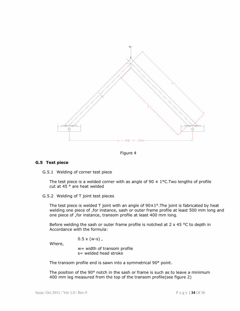
c. Corner weld sample for compression bending test (see figure 3) d. T joint weld samples for compression bending test (see figure 4)
Issue: Oct 2011 / Ver 1.0 / Rev 0 P a g e | 33 Of 56
1
3
4
1 Clamping device
2 Rigid support over a minimum clamping length of 400mm
3 Frame
4 Optional support block (5 +/- 0.5) mm
F1
1
3
4
1 Clamping device
2 Rigid support over a minimum clamping length of 400mm
3 Frame
4 Optional support block (5 +/- 0.5) mm
F1
Figure 1- Weld Test Apparatus Figure 2 : T Arragement
Fc
Figure 3
Issue: Oct 2011 / Ver 1.0 / Rev 0 P a g e | 34 Of 56
Fc
Figure 4
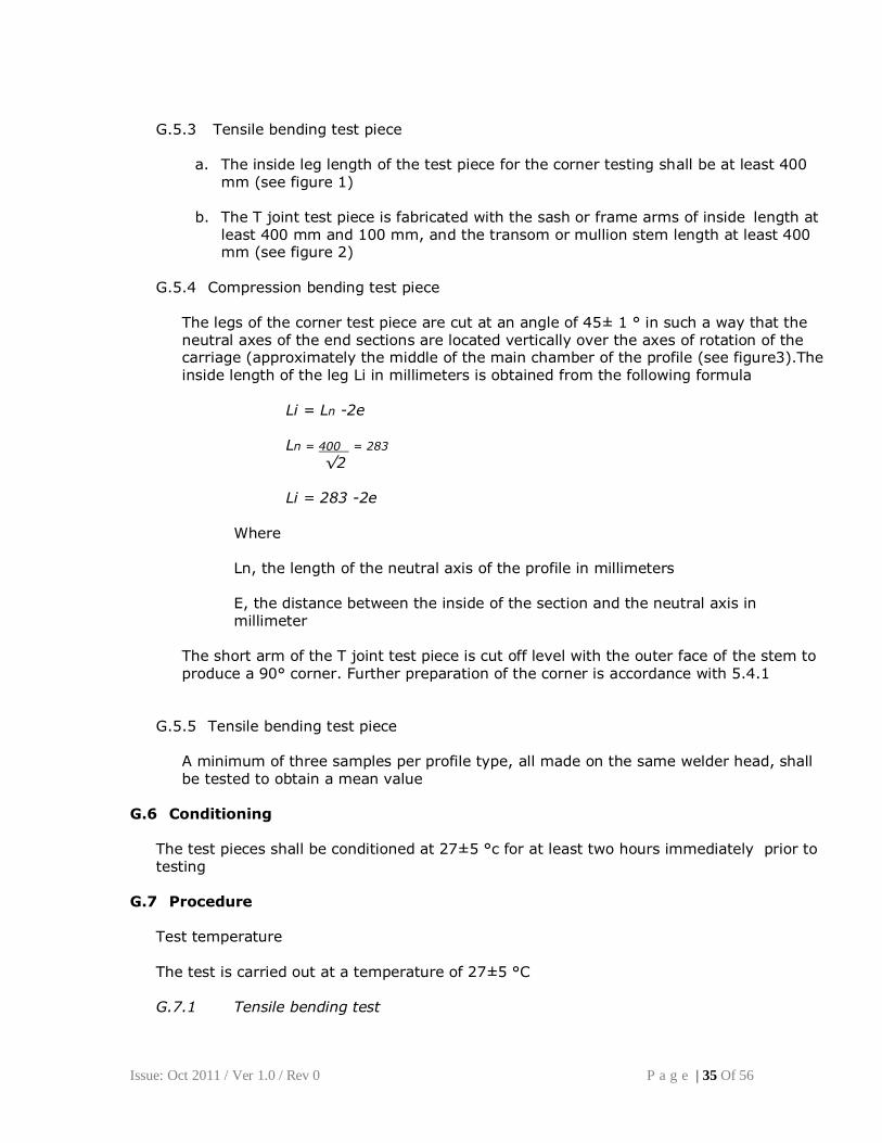
G.5 Test piece G.5.1 Welding of corner test piece
The test piece is a welded corner with as angle of 90 ± 1°C.Two lengths of profile cut at 45 ° are heat welded G.5.2 Welding of T joint test pieces The test piece is welded T joint with an angle of 90±1°.The joint is fabricated by heat welding one piece of ,for instance, sash or outer frame profile at least 500 mm long and
one piece of ,for instance, transom profile at least 400 mm long. Before welding the sash or outer frame profile is notched at 2 x 45 °C to depth in Accordance with the formula: 0.5 x (w-s) ,
Where,
w= width of transom profile s= welded head stroke The transom profile end is sawn into a symmetrical 90° point. The position of the 90° notch in the sash or frame is such as to leave a minimum 400 mm leg measured from the top of the transom profile(see figure 2)
Issue: Oct 2011 / Ver 1.0 / Rev 0 P a g e | 35 Of 56
G.5.3 Tensile bending test piece
a. The inside leg length of the test piece for the corner testing shall be at least 400
mm (see figure 1)
b. The T joint test piece is fabricated with the sash or frame arms of inside length at least 400 mm and 100 mm, and the transom or mullion stem length at least 400 mm (see figure 2)
G.5.4 Compression bending test piece The legs of the corner test piece are cut at an angle of 45± 1 ° in such a way that the neutral axes of the end sections are located vertically over the axes of rotation of the carriage (approximately the middle of the main chamber of the profile (see figure3).The inside length of the leg Li in millimeters is obtained from the following formula Li = Ln -2e
Ln = 400 = 283
√2 Li = 283 -2e Where Ln, the length of the neutral axis of the profile in millimeters E, the distance between the inside of the section and the neutral axis in millimeter The short arm of the T joint test piece is cut off level with the outer face of the stem to
produce a 90° corner. Further preparation of the corner is accordance with 5.4.1 G.5.5 Tensile bending test piece A minimum of three samples per profile type, all made on the same welder head, shall be tested to obtain a mean value
G.6 Conditioning The test pieces shall be conditioned at 27±5 °c for at least two hours immediately prior to testing
G.7 Procedure Test temperature The test is carried out at a temperature of 27±5 °C G.7.1 Tensile bending test
Issue: Oct 2011 / Ver 1.0 / Rev 0 P a g e | 36 Of 56
Clamp the test piece in the apparatus as shown in figures 1 or 2.Contoured support block may be used, if necessary, to limit twisting.
Apply the load to the test piece in such a way that the speed of application is 50 mm / min. Continue until the test piece fails. G.7.2 Compression bending test Place the test piece on the trolley as shown in figures 3 or 4.In order to avoid excessive deflection, the open frame end of the T joint can be supported in the corner area by inserting a cavity filling block(e.g. a piece of metal reinforcement or wooden block). Apply the load to the test piece in such a way that the speed of application is 50 mm/min. Continue until the test piece fails
G.8 Test Report
The test report shall include the following information: a. reference to this standard; b. the name of the test laboratory; c. full identification of the joint 1. the type of joint (corner or T joint) 2. the presence or absence of welding sprue (bead) 3. if more than one welding head is in use, the nominated head; e. the date of testing; f. the welding conditions; g. the test method(tensile bending or compression bending)
h. for compression bending testing the inside length of the leg of the test piece; i. the test temperature; j. the failure load of every test piece; k. the calculated failure stress for every test piece and the average failure stress l. all operating details not specified in this standard, as well as any incidents likely to have influence the result
Issue: Oct 2011 / Ver 1.0 / Rev 0 P a g e | 37 Of 56
Annexure H Method for calculation of failure stress
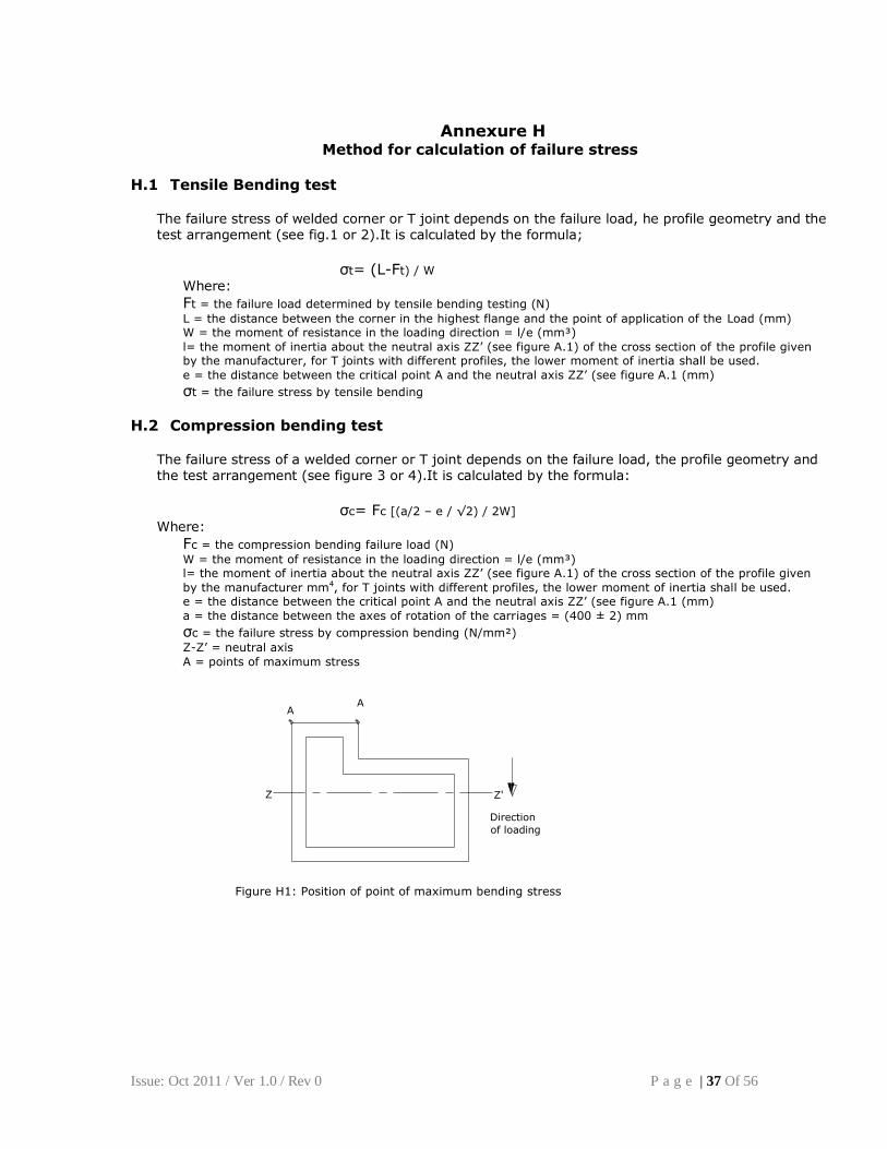
H.1 Tensile Bending test The failure stress of welded corner or T joint depends on the failure load, he profile geometry and the test arrangement (see fig.1 or 2).It is calculated by the formula;
σt= (L-Ft) / W
Where:
Ft = the failure load determined by tensile bending testing (N)
L = the distance between the corner in the highest flange and the point of application of the Load (mm) W = the moment of resistance in the loading direction = l/e (mm³)
l= the moment of inertia about the neutral axis ZZ’ (see figure A.1) of the cross section of the profile given by the manufacturer, for T joints with different profiles, the lower moment of inertia shall be used.
e = the distance between the critical point A and the neutral axis ZZ’ (see figure A.1 (mm)
σt = the failure stress by tensile bending
H.2 Compression bending test The failure stress of a welded corner or T joint depends on the failure load, the profile geometry and the test arrangement (see figure 3 or 4).It is calculated by the formula:
σc= Fc [(a/2 – e / √2) / 2W]
Where:
Fc = the compression bending failure load (N)
W = the moment of resistance in the loading direction = l/e (mm³) l= the moment of inertia about the neutral axis ZZ’ (see figure A.1) of the cross section of the profile given
by the manufacturer mm4, for T joints with different profiles, the lower moment of inertia shall be used. e = the distance between the critical point A and the neutral axis ZZ’ (see figure A.1 (mm)
a = the distance between the axes of rotation of the carriages = (400 ± 2) mm
σc = the failure stress by compression bending (N/mm²)
Z-Z’ = neutral axis
A = points of maximum stress
AA
Z Z'
Direction
of loading
Figure H1: Position of point of maximum bending stress
Issue: Oct 2011 / Ver 1.0 / Rev 0 P a g e | 38 Of 56
Annexure I
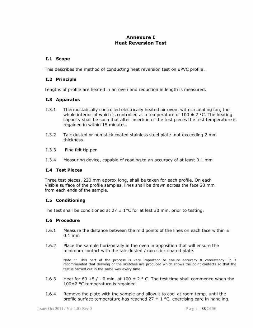
Heat Reversion Test
I.1 Scope
This describes the method of conducting heat reversion test on uPVC profile. I.2 Principle
Lengths of profile are heated in an oven and reduction in length is measured. I.3 Apparatus I.3.1 Thermostatically controlled electrically heated air oven, with circulating fan, the
whole interior of which is controlled at a temperature of 100 ± 2 °C. The heating capacity shall be such that after insertion of the test pieces the test temperature is
regained in within 15 minutes.
I.3.2 Talc dusted or non stick coated stainless steel plate ,not exceeding 2 mm thickness
I.3.3 Fine felt tip pen
I.3.4 Measuring device, capable of reading to an accuracy of at least 0.1 mm
I.4 Test Pieces Three test pieces, 220 mm approx long, shall be taken for each profile. On each Visible surface of the profile samples, lines shall be drawn across the face 20 mm from each ends of the sample.
I.5 Conditioning The test shall be conditioned at 27 ± 1°C for at lest 30 min. prior to testing. I.6 Procedure
I.6.1 Measure the distance between the mid points of the lines on each face within ±
0.1 mm I.6.2 Place the sample horizontally in the oven in apposition that will ensure the
minimum contact with the talc dusted / non stick coated plate.
Note 1: This part of the process is very important to ensure accuracy & consistency. It is
recommended that drawing or the sketches are produced which shows the point contacts so that the
test is carried out in the same way every time. I.6.3 Heat for 60 +5 / - 0 min. at 100 ± 2 ° C. The test time shall commence when the
100±2 °C temperature is regained. I.6.4 Remove the plate with the sample and allow it to cool at room temp. until the
profile surface temperature has reached 27 ± 1 °C, exercising care in handling.
Issue: Oct 2011 / Ver 1.0 / Rev 0 P a g e | 39 Of 56
I.6.5 Measure the distance between the mid points of the lines on each face and calculate the reversion as follows:
% reversion = measured distance x 100 Original measurement length
I.6.6 Record the individual values of each face of each of the three samples and
calculate the mean reversion for each of the three samples in accordance with the requirement in 5.4
Note 2: The measurement should be made along the chord of the curved sample and not along the
centerline of the sample.
The main profiles tested shall have a mean reversion up to 2% and there shall not be more than a 0.4% difference between two faces. Note: for ancillary profiles there is no requirement for difference of individual surfaces. The use of
dark external glazing bead or ancillary profiles necessitates lower reversion.
Issue: Oct 2011 / Ver 1.0 / Rev 0 P a g e | 40 Of 56
Annexure – K
METHOD OF TESTING WATER TIGHTNESS
1. Scope
This annexure defines the conventional method to be used to determine the water tightness of
completely assembled windows and doors of any materials.
2. Field of Application
This test method is designed to take account of conditions in use, when the window or door is
installed in accordance with the manufacturer’s specification and the requirements Indian
Standards and codes of practice. This annexure does not apply to the joints between the window
or door frame and the building construction.
3. Definition
3.1. test pressure
difference between the static air pressures on the external face and the internal face of the test
specimen.
Test pressure is positive if the static air pressure on the external face is higher than that on the
internal face.
3.2. watertightness
the ability of the closed and fastened test specimen to resist water penetration under the test
conditions up to a pressure. (Pmax =limit of the watertightness).
3.3. water penetration
continuous or repeated wetting of the internal surface of the test specimen or parts which are not
designed to be wetted when water drains back to external face.
3.4. limit of watertightness
maximum test pressure Pmax up to which the test specimen remains watertight under the test
conditions for the specified time.
4. Principle
Constant spraying of a specified quantity of water onto the external surface of the test specimen
while increments of positive test pressure are applied at regular intervals during which details
are recorded of test pressure and location of water penetration.
5. Apparatus
5.1.
A chamber with an open side to which the test specimen can be fitted. It shall be constructed so
as to be able to withstand the test pressures without deflecting to an extent likely to influence
the test results.
5.2.
Means for applying controlled test pressure to test specimen.
Issue: Oct 2011 / Ver 1.0 / Rev 0 P a g e | 41 Of 56
5.3.
Means of producing rapid changes in test pressure, controlled within defined limits.
5.4.
Instrument suitable for measuring the quantity of water supplied within an accuracy of ± 10 %.
If several rows of nozzles with different flows are included, at least two such instruments are
needed.
5.5.
Means of measuring the test pressure applied across the specimen, within an accuracy of± 5%. 5.6.
A spraying system capable of applying a continuous regularly dispersed film of water, all over
the surface likely to be wetted in real exposure conditions, by means of full circular cone
nozzles with the following features:
a) angle of spay: ( )°
b) pressure working range : 2 bar to 3 bar according to manufacturer's specifications
c) nozzle rate : top row 2 1/min ± 0.2 l/min per nozzle
additional rows 1 1/min ± 0,1 1/min per nozzle
and 2 1/min ± 0,2 1/min per nozzle (see 6.2.4).
6. Preparation of test specimen
6.1. Set-up of the test specimen
The test specimen shall be fixed as intended for use in the works without any twists or bends
which may influence the test results. The test specimen shall be fully operable.
The surround shall be prepared and installed so that any water penetration, including that
through the frame joints, shall be readily detectable.
The test specimen shall be cleaned and surfaces dry.
Ventilation devices, if any, shall be taped over.
6.2. Set-up spraying system (see figure 1 to figure 3)
The location and the size of the specimen in the intended works shall be taken into account
when selecting the method of spraying.
A test shall be carried out using only one set up. A template is recommended to set up the
spraying system.
6.2.1. Positioning of the line connecting the nozzle tips (the nozzle line)
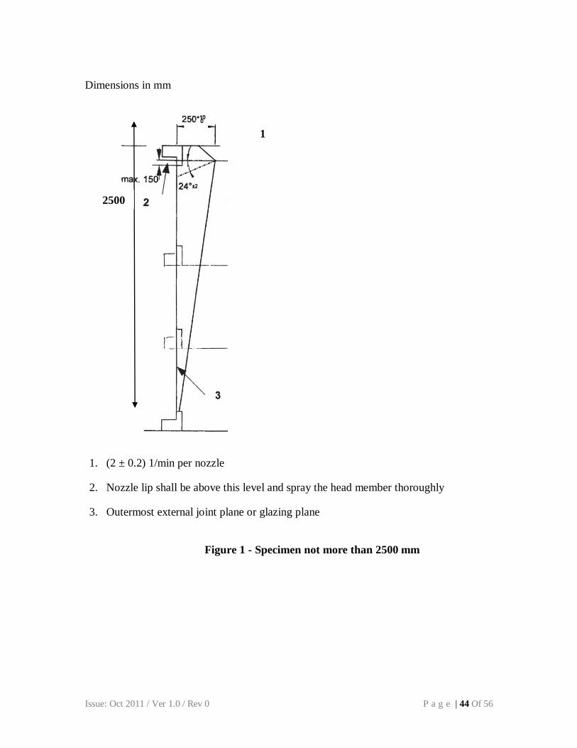
The nozzle line shall be located not more than 150 mm above the topmost horizontal joint line
of any moving frame or the glazing line of any fixed glazing, in order to provide complete
wetting of the adjacent horizontal frame member(s).The nozzle line shall be located at a
distance of ( ) mm from the external face of the specimen as defined by the outermost
external joint plane of moving parts or the glazing plane of fixed parts.
Issue: Oct 2011 / Ver 1.0 / Rev 0 P a g e | 42 Of 56
6.2.2. Positioning relative to specimen width
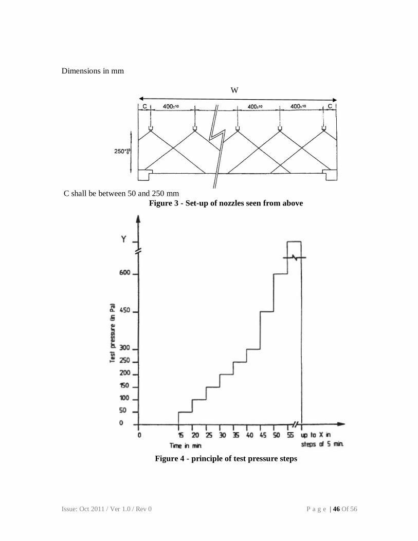
Nozzles shall be spaced at 400 mm ± 10 mm along the axis of the spray bar and the nozzles
shall be arranged in order that the lateral distance "c" between the outer edge of the surround
and the outermost nozzles shall be greater than 50 mm but not exceeding 250 mm, see figure 3.
6.2.3. Direction of nozzle spray
The nozzle axis shall lie on a line ( )° below the horizontal line see figure 1.
6.2.4. Number of nozzle rows
6.2.4.1. For specimens with a height up to 2.5 m measured from the topmost horizontal joint line of
any moving frame or glazing line of any fixed glazing to the next joint, see figure 1, a single
row of nozzles shall be used, with each nozzle spraying on average 2l/min/m2.
6.2.4.2. For specimens exceeding 2.5 m height, see figure 2, an upper row of nozzles shall be fixed
as described in 6.2.4.1. Additional rows of nozzles shall be fixed at vertical intervals at 1.5 m
(within a tolerance of± 150 mm) below the top nozzle line. Where any horizontal projection
occurs, these additional rows shall be installed at a level such that no water is sprayed upwards
under the projection.
6.2.4.3. For specimens containing one or more horizontal waterbars which project more than 50 mm.
See figure 5, an additional row of nozzles, as described in 6.2.4.2 shall be arranged for each
waterbar as shown in figure 2.
6.3. Water characteristics
Water temperature shall be between 4°C and 30°C and the water shall be clean enough to ensure
that all nozzles spray correctly.
7. Test procedure
7.1. Preliminaries
The test specimen shall be conditioned for at least 4 h within the range 10°C to 30°C and 25 %
to 75 % RH immediately before testing.
Temperature shall be measured to within ± 3°C and humidity to within ±5 %. Atmospheric
pressure shall be measured to within ± 1 kPa.
All the opening parts of the test specimen shall be opened and closed at least once before finally
being secured in the closed position.
If an air permeability test has not been performed during the previous 24 h, three test pressure
pulses shall be applied, the duration of increase in test pressure shall not be less than 1 s. Each
pulse shall be maintained for at least 3 s. These pulses shall produce a test pressure 10 % greater
than the maximum test pressure required for the test, without, however being less than 500 Pa.
7.2. Spraying phase
Spraying is applied first with the test pressure of 0 Pa for 15 min then with the test pressure
increasing every 5 min, see figure 4. Overall duration is dependent on the watertightness of the
test specimen. The duration of each pressure steps shall be within a tolerance of ( min.
Issue: Oct 2011 / Ver 1.0 / Rev 0 P a g e | 43 Of 56
The test pressure shall be applied in steps of 50 Pa up to 300 Pa and from 300 Pa in steps of 150
Pa. Immediately prior to testing the flow of each row of nozzles shall be adjusted according to
5.6.
7.3. Test results
Report the location and pressure at which any water penetrated the specimen and the time for
which the maximum pressure was maintained before water penetrated. Mark this data on a
drawing of the face view of the test specimen.
8. Test report
This shall state the devices used for the test and record on a drawing or a photograph of the test
specimen the location of any significant water penetration observed.
The report shall contain as a minimum the following information:
- reference to this test ;
- the name of the test institution ;
- date of the test ;
- all necessary references to identify the- specimen and the method of selection-of .the test
;
- all relevant details concerning the dimensions of the specimen, its materials, design,
construction and manufacture and its surface finish and fittings ;
- drawings of details of the specimen including cross section to a scale of 1:2 or larger ;
- presence of ventilation, type and condition {i.e. closed, taped over etc.);
- test procedures, including storage and conditioning prior to test, and mounting the test
specimen ready for test;
- test climates used.
Issue: Oct 2011 / Ver 1.0 / Rev 0 P a g e | 44 Of 56
Dimensions in mm
1. (2 ± 0.2) 1/min per nozzle
2. Nozzle lip shall be above this level and spray the head member thoroughly
3. Outermost external joint plane or glazing plane
Figure 1 - Specimen not more than 2500 mm
1
2500
Issue: Oct 2011 / Ver 1.0 / Rev 0 P a g e | 45 Of 56
Dimensions in mm
1. limit of spray
2. 1500 or less
Figure 2 - Specimen more than 2 500 mm or with horizontal waterbar
projecting more than 50 mm (see figure 5)
Issue: Oct 2011 / Ver 1.0 / Rev 0 P a g e | 46 Of 56
Dimensions in mm
C shall be between 50 and 250 mm
Figure 3 - Set-up of nozzles seen from above
Figure 4 - principle of test pressure steps
W
Issue: Oct 2011 / Ver 1.0 / Rev 0 P a g e | 47 Of 56
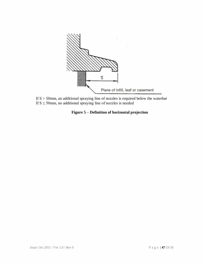
If S > 50mm, an additional spraying line of nozzles is required below the waterbar
If S ≤ 50mm, no additional spraying line of nozzles is needed
Figure 5 – Definition of horizontal projection
Issue: Oct 2011 / Ver 1.0 / Rev 0 P a g e | 48 Of 56
Annexure – L
METHOD OF TESTING WIND RESISTANCE
1 Scope
The ISO 6612 – 1980 defines the method of testing to be used for assessing the structural
performance, under positive or negative static air pressure of windows to be fitted in exterior walls
and supplied in the form of completely assembled and finished units.
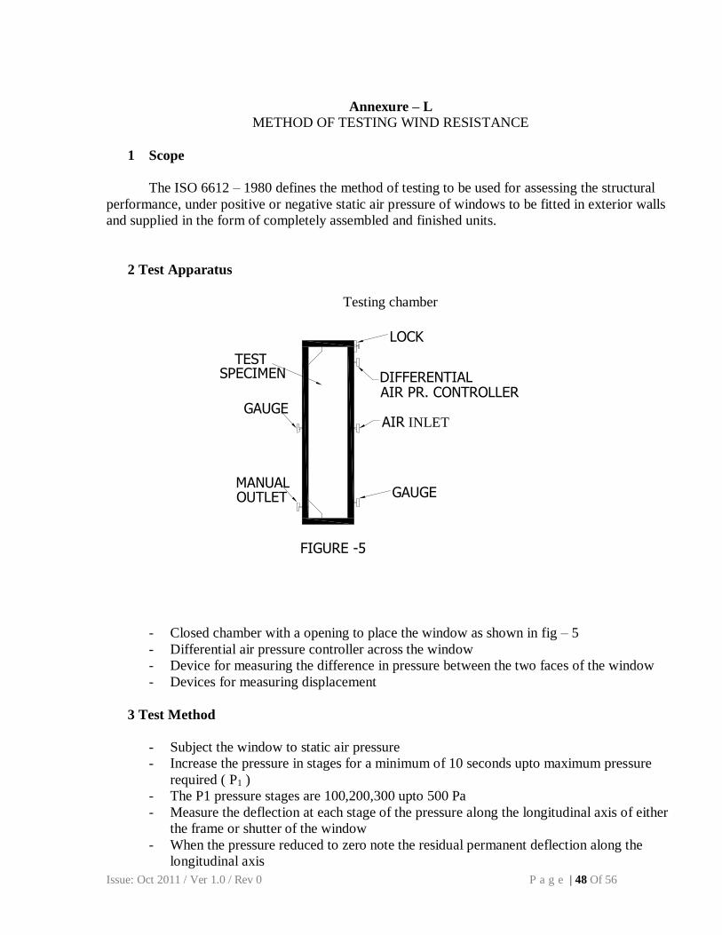
2 Test Apparatus
Testing chamber
- Closed chamber with a opening to place the window as shown in fig – 5
- Differential air pressure controller across the window
- Device for measuring the difference in pressure between the two faces of the window
- Devices for measuring displacement
3 Test Method
- Subject the window to static air pressure
- Increase the pressure in stages for a minimum of 10 seconds upto maximum pressure
required ( P1 )
- The P1 pressure stages are 100,200,300 upto 500 Pa
- Measure the deflection at each stage of the pressure along the longitudinal axis of either
the frame or shutter of the window
- When the pressure reduced to zero note the residual permanent deflection along the
longitudinal axis
LOCK
GAUGE
GAUGE AIR INLET
MANUAL OUTLET
DIFFERENTIAL AIR PR. CONTROLLER
TEST SPECIMEN
FIGURE -5
Issue: Oct 2011 / Ver 1.0 / Rev 0 P a g e | 49 Of 56
4 Repeated Pressure test
- The window shall be subjected to n – pressure impulses between 0 and P2
- The period of transition from one pressure value to another shall not be less then 1
seconds
- The pressure shall be held at their maximum or minimum values for at least
3 seconds at each impulse
- After completion of the test open and close the moving parts of the window 5
times and note the damages or functioning defect detected after this test
5 Safety Test
- The maximum required pressure P3 shall be reached as quick as possible but
not less then 1second and held for 3 second
- Note any deformations, damages or functioning defects detected after the test
6 Report the test value
Issue: Oct 2011 / Ver 1.0 / Rev 0 P a g e | 50 Of 56
Annexure – M
METHOD OF TESTING AIR PERMEABILITY OF WINDOWS
1. Scope
This annexure defines the conventional method to be used to determine the air permeability of
completely assembled uPVC windows and doors to be fitted in exterior walls, when submitted
to positive or negative test pressures.
2. Field of application
This test method applies to all windows including door height windows in their normal
operating condition for which they are designed and installed according to the manufacturer’s
recommendations as in a finished building, bearing in mind the conditions of test as defined
below. This test method does not apply to the joints between the windows and surrounding
components and material
3. Definition
3.1.pressure differential:
Difference between the static air pressure on the external surface of a window and the static air
pressure on the internal surface of the same window
The difference is positive when the external pressure is higher than the internal pressure. In the
opposite case, it is negative. This pressure is expressed in Pascals
3.2.air permeability:
The property of a closed window to let air pass when it is subjected to a differential pressure
The air permeability is characterized by a flow of air, in standard conditions, expressed in cubic
meters per hour as a function of the pressure.
3.3.opening joint:
line of discontinuity between:
either a frame and its matched component which can be opened by means of its hardware,
see figure 1;
or two components which can be opened by means of their hardware, see figure 2.
Conventionally, this discontinuity is as seen from the inside face of the test specimen.
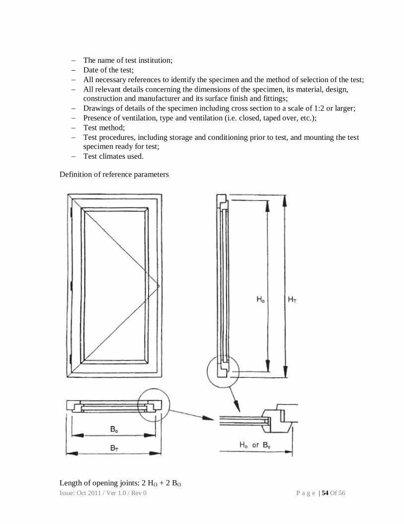
3.4.length of opening joint:
length of the line of frame, sash, casement, leaf or infilling, as seen from the inside face,
separating the two contiguous components, determined as shown in figure 1 and figure 2.
Actual length of gaskets or seals fitted into the underlying profiles of the components or joints
of components built into opening parts are not relevant. The length of joint shall be expressed in
meters (m).
Issue: Oct 2011 / Ver 1.0 / Rev 0 P a g e | 51 Of 56
3.5.overall area:
area of the test specimen measured parallel to the glazing or the leaf, see figure 1 and figure 2
The overall area shall be expressed in square meters (m2).
3.6.standard conditions:
For the purpose of the test, the following are considered the standard conditions for determining
air flow
temperature: 20ºC
pressure: 101.3 kPa
air density: 1.202 kg/m3
4. Principle of test
Application of a defined series of test pressures (positive and negative) and at each test pressure
measurement of the air permeability with a suitable test device.
5. Test apparatus
5.1. A chamber with an open side to which the test specimen can be fitted. It shall be
constructed so as to be able to withstand the test pressures without deflecting to an extent
likely to influence the test results.
5.2. Means for applying controlled test pressure to test specimen.
5.3. Means of producing rapid changes in test pressure, controlled within defined limits.
5.4. Instrument suitable for measuring the quantity of air flow into or out of the chamber within
an accuracy of ± 5% (calibrated at + 20ºC, 101 kPa).
5.5. Means of measuring the test pressure applied across the specimen, within an accuracy of ±
5%.
5.6. Means of sealing all joints of the specimen when required.
6. Preparation of test specimen
A surround for the specimen to be tested shall be prepared. This shall be stiff enough to
withstand the test pressures without deflecting to an extent likely to impair jointing or to impose
bending stresses on the test specimen. When the installation conditions are known, the specimen
shall be installed to simulate these, wherever practical.
The test specimen shall be fixed as intended for use in the works without any twists or bends
which may influence the test results. The specimen shall be fully operable. The test specimen
shall be cleaned and surfaces dry. Ventilation devices, if any, shall be taped over, except when it
is required to determine the amount of air flow through such devices.
Issue: Oct 2011 / Ver 1.0 / Rev 0 P a g e | 52 Of 56
The thickness, type of glass and method of glazing shall comply with the requirements of the
manufacturer. When there is no specification or when there is a possibility that the window will
be used with different glasses, test shall be carried out with a glass of minimum thickness with
respect to the surface area.
7. Test procedure
7.1. Preliminaries
The ambient temperature and humidity close to the specimen shall be within the range 10ºC to
30ºC and 25% to 75% RH and the specimen shall be conditioned thus for at least 4 h
immediately before testing.
Temperature shall be measured to within ± 3 ºC and relative humidity to within ± 5%.
Atmospheric pressure shall be measured to within ± 1 kPa.
The test pressure shall be applied in steps of 50 Pa upto 300 Pa and from 300 Pa in steps of 150
Pa. the air permeability result shall be given to an accuracy of 10%.
7.2. Air permeability of test chamber
Determine the procedure to follow in accordance with what is known about the air permeability
of the test chamber.
7.2.1.Test chamber with known air permeability
Assume the air permeability of the test chamber is zero if it is less than 5% of the maximum air
permeability permitted throughout the range of the classification that is attributed to the test
specimen.
When this is not so, measure the air permeability of the test chamber as described in 7.2.2
unlessit is known and shown to be approximately constant within the limit of accuracy of the
measurement recorded by the test laboratory.
In no case shall the air permeability of the test chamber exceed 30% of the overall air
permeability of the test specimen and the test chamber.
7.2.2.Test chamber with unknown air permeability
Seal all joints in the test specimen with adhesive tape or an airtight sheet covering the whole test
specimen. Measure the air permeability of the test chamber with positive test-pressures as
described in 7.3.1. When it is intended to carry out an air permeability test with negative test
pressures, measure the air permeability of the test chamber with negative test pressures as
described in 7.3.1.
Remove the adhesive tape or airtight sheet covering the test specimen.
Issue: Oct 2011 / Ver 1.0 / Rev 0 P a g e | 53 Of 56
7.3. Overall air permeability of test specimen and the test chamber-Positive pressures
Open and close all opening parts of the test specimen at least once before securing them in the
closed position.
Measure the air permeability of the test specimen with positive test pressures as described in
7.3.1 see figure A
7.3.1.Measurement of air permeability
Apply three pressure pulses each 10% greater than the maximum test pressure to be used in the
test or 500 Pa, whichever is greater. The time to reach the maximum test pressure shall be not
less than 1 s and the pressure shall be sustained for at least 3s. Apply positive test pressure steps
as specified in 7.1. Measure and record the air permeability at each step. The duration of each
step shall be sufficient to allow the test pressure to stabilize before the air permeability is
measured.
7.4. Overall air permeability of test specimen and the test chamber – Negative pressures
Perform this test only when specifically required. Open and close all opening parts of the test
specimen at least once before securing them in the closed position. Measure the air permeability
of the test specimen and test chamber with negative pressures as described in 7.3.1, see Figure
A.
8. Test result
8.1.Adjust the result of the air flow measurements (Vx) at each step, to calculate the air flow (Vo) at
normal conditions (To = 293 k, Po = 101.3 kPa), considering the actual Tx expressing in ºC and
atmospheric pressure Px, expressed in kPa, during the test.
Vo = Vx. 293 . Px .
273 + Tx 101.3
8.2.For a specimen the air permeability at each step is equal to the overall air permeability adjusted
in accordance with 8.1 less the air permeability of the chamber, when at zero, adjusted in
accordance with 8.1
8.3. Using the length of the opening joint as defined in 3.4 and the overall area as defined in 3.5
calculate the air permeability in terms of m3 and m
3 , expressing the results to two significant
figures h.m h.m2
9. Test report
This shall state the airflow measurement devices used for the test and record on a drawing or a
photograph of the test specimen, the location of any significant points or air leakage observed.
Where appropriate the report shall contain as a minimum the following information:
Reference to this test;
Issue: Oct 2011 / Ver 1.0 / Rev 0 P a g e | 54 Of 56
The name of test institution;
Date of the test;
All necessary references to identify the specimen and the method of selection of the test;
All relevant details concerning the dimensions of the specimen, its material, design,
construction and manufacturer and its surface finish and fittings;
Drawings of details of the specimen including cross section to a scale of 1:2 or larger;
Presence of ventilation, type and ventilation (i.e. closed, taped over, etc.);
Test method;
Test procedures, including storage and conditioning prior to test, and mounting the test
specimen ready for test;
Test climates used.
Definition of reference parameters
Length of opening joints: 2 HO + 2 BO
Issue: Oct 2011 / Ver 1.0 / Rev 0 P a g e | 55 Of 56
Overall area: HT x BT
Figure 1: Single leaf operation
Length of opening joints: 3 HO + 2 BO
Overall area: HT x BT
Figure 1: Double leaf operation
Issue: Oct 2011 / Ver 1.0 / Rev 0 P a g e | 56 Of 56
Air Permeability
Test pressure sequence for air tight chambers
Test pressure sequence for non air tightness chambers
Figure A
Issue: Oct 2011 / Ver 1.0 / Rev 0 P a g e | 57 Of 56
Annexure – N
METHOD OF CALCULATING STRENGTH OF WINDOWS & DOORS
1. Scope
This annexure describes the method to be used to determine the window strength required to
meet specific wind load of the region / building laid down as per IS 875.
2. Method of Calculation
The strength of window can be calculated as per procedure laid down in the subsequent section
2.1. Wind Load as per IS 875-III
The customer may specify the wind load or may be calculated as per the IS875-III. Below
is guideline for wind load calculation (Note: The parameters should be validated with customer) a. Basic wind speed = Vb in m/sec
b. Risk factor = K1
c. Terrain category = K2 d. Topography factor = K3
e. Building Height = H in m
f. Pressure Coefficient = Cp
g. H/L Ratio = HL h. L/W Ratio = LW
i. Max wind load, P = Cp.(0.6).(Vb.K1.K2.K3)2 Pascal
The wind load, P, calculated above is the max load which the window is subjected to.
2.2. Desired Structural Strength of uPVC Window
A typical slider window is illustrated in Fig 1 and the trapezoidal load distribution on the
window is shown in the adjoining illustration Fig 2.
Issue: Oct 2011 / Ver 1.0 / Rev 0 P a g e | 58 Of 56
The total wind load is divided in two part which can be unequal part. As per the
trapezoidal load distribution in Fig 2, the load on the frame (fixed to the wall with fastener
all around) is considered negligible.
The EI value required for section can be calculated as per the below formulae. (Refer Fig
B-1-3)
where,
Example: Now considering the values,
a or b = 450
W = 1000 Pa (as specified by customer or calculated as per 2.1)
L/Def. = 1/175
L = 2450 mm
The required EI value for Sash as per Eqn (1) will be,
EI (required) = 14.28 x 10⁹ N-mm
2
2.3. Calculating Actual Structural Strength of uPVC Window
Fig 1 Fig 2
Eq (1)
Issue: Oct 2011 / Ver 1.0 / Rev 0 P a g e | 59 Of 56
For the sake of simplicity, it is proposed to use only the data of steel for strength
calculation. Strength of PVC and other accessories are quite low and are factored as safety
factor.
The second moment of inertia for steel reinforcement section is obtained from the CAD
data, Iyy = 90196.19 mm4 (Refer Fig. 3)
Young’s modulus for steel is, E = 210GPa,
Therefore,
EIyy(reinf) = 18.94 x 10⁹ N-mm
2
2.4. Comparing and result interpretation
The said window can considered to be passing the strength requirement, if following co-
relation holds true.
Actual EIyy(reinf) ≥ EI (required)
2.5. Reporting the result
Following parameters should be reported in the report
2.5.1. Wind load as stated by the customer or wind load calculations as described in section
2.1 with all parameters used for the calculations
2.5.2. Desired Strength as stated in section 2.2
2.5.3. Actual strength as stated in section 2.3. The steel cross section should be added with
moment of inertia value. E value of the steel used
2.5.4. Result of acceptance or failure.
Fig 3
Issue: Oct 2011 / Ver 1.0 / Rev 0 P a g e | 60 Of 56
Bibliography
EN 12608 Unplasticized Poly Vinyl Chloride (uPVC) profiles for the fabrication
of windows and doors – Classification, requirements and test
methods
BS 7413 Unplasticized Poly Vinyl Chloride (uPVC) profiles for windows and
doors - Specifications
ASTM D Standard specification for Rigid Poly Vinyl Chloride (PVC) exterior 4726
profile extrusions used for assembled windows and doors
ASTM D Standard practice for Xenon Arc exposure of plastics intended for 2565-