US 2009015O163A1 (19) United States (12) Patent Application Publication (10) Pub. No.: US 2009/0150163 A1 Martin (43) Pub. Date: Jun. 11, 2009 (54) METHOD AND APPARATUS FOR Publication Classification MULTCHANNEL UPMXING AND (51) Int. Cl DOWNMIXING GIOL 2L/00 (2006.01) (76) Inventor: Geoffrey Glen Martin, Vinderup (DK) (52) U.S. Cl. ........................................................ 704/SOO Correspondence Address: STITES & HARBSON PLLC (57) ABSTRACT 1199 NORTH FAIRFAX STREET, SUITE 900 Loudspeakers in domestic or automotive environments are ALEXANDRIA, VA 22314 (US) rarely placed ideally with respect to the sources Supplying them, and the stereo and Surround images are seldom satis (21) Appl. No.: 11/719,820 fying. According to the invention there is provided a method 1-1. and apparatus for combining a precise knowledge about the (22) PCT Filed: Nov. 21, 2005 relative positions of the loudspeakers that were intended (the (86). PCT No.: PCT/B05/53830 virtual loudspeakers) and a precise knowledge about the actual placement of listening loudspeakers into a vector space S371 (c)(1) that enables calculation of running corrections to the signals (2), (4) Date: May 21, 2007 used in order to simulate the presence of the virtual loud speakers. Specifically the corrections may comprise gain/ (30) Foreign Application Priority Data attenuations determined based on the distances in vector space between the virtual and actual loudspeakers and delays Nov. 22, 2004 (DK) .......................... PA 2004-01816 determined from these distances. s c 34 E E rew - a was ?so us dw W. wrov was 3. 35 input Channels 32 N-- Left Front 32-N- CentreFront 3 2-N- Right Front 32-N- left Surround A & A. As a saw no w w w F w J2-i-N- Right Surround - - - - - - - - - - ------------ a vet up to 8 & Pw us it up up up vow we up was as we as we
Transcript
US 2009015O163A1
(19) United States (12) Patent Application Publication (10) Pub. No.: US 2009/0150163 A1
Martin (43) Pub. Date: Jun. 11, 2009
(54) METHOD AND APPARATUS FOR Publication Classification MULTCHANNEL UPMXING AND (51) Int. Cl DOWNMIXING GIOL 2L/00 (2006.01)
Correspondence Address: STITES & HARBSON PLLC (57) ABSTRACT 1199 NORTH FAIRFAX STREET, SUITE 900 Loudspeakers in domestic or automotive environments are ALEXANDRIA, VA 22314 (US) rarely placed ideally with respect to the sources Supplying
them, and the stereo and Surround images are seldom satis (21) Appl. No.: 11/719,820 fying. According to the invention there is provided a method
1-1. and apparatus for combining a precise knowledge about the (22) PCT Filed: Nov. 21, 2005 relative positions of the loudspeakers that were intended (the (86). PCT No.: PCT/B05/53830 virtual loudspeakers) and a precise knowledge about the
actual placement of listening loudspeakers into a vector space S371 (c)(1) that enables calculation of running corrections to the signals (2), (4) Date: May 21, 2007 used in order to simulate the presence of the virtual loud
speakers. Specifically the corrections may comprise gain/ (30) Foreign Application Priority Data attenuations determined based on the distances in vector
space between the virtual and actual loudspeakers and delays Nov. 22, 2004 (DK) .......................... PA 2004-01816 determined from these distances.
a vet up to 8 & Pw us it up up up vow we up was as we as we
Patent Application Publication Jun. 11, 2009 Sheet 1 of 11 US 2009/015O163 A1
Patent Application Publication Jun. 11, 2009 Sheet 2 of 11 US 2009/015O163 A1
f ---, J f Ya s S.
Y Y. v V W f -a 6 2 y
W f
w w
V W w F W
W Y.
p f
W Y f
w
w Wy ear we
s
r r ?
- Y. e." s
1 . r
- s. A A. s Ap v f a 1 n- f
Van ra pe 1a/
Patent Application Publication Jun. 11, 2009 Sheet 3 of 11 US 2009/015O163 A1
w A. 12 N- Sg.N- 43 1, YY A. V
y V
' Y y
W.
w
V V
w
W t w W w
w
W a Wr
Patent Application Publication Jun. 11, 2009 Sheet 4 of 11 US 2009/015O163 A1
Patent Application Publication Jun. 11, 2009 Sheet 5 of 11 US 2009/015O163 A1
fly input 1 delay 1
45
Output
Patent Application Publication Jun. 11, 2009 Sheet 6 of 11 US 2009/015O163 A1
3 6 34 6 3 6
s 7 th 5 7
6
Fi 9. 6
Patent Application Publication Jun. 11, 2009 Sheet 7 of 11 US 2009/015O163 A1
Patent Application Publication Jun. 11, 2009 Sheet 8 of 11 US 2009/015O163 A1
3
input Channels
32 N-- Left Front
32-N- CentreFront
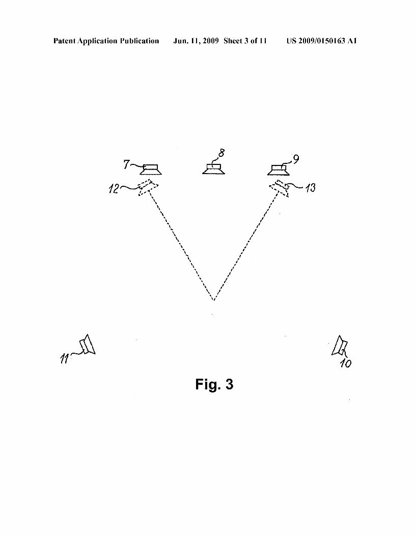
Right Front 32-N-
32-N- left Surround
J2-N- Right Surround Output Channels Left :
69 70 Right
Patent Application Publication Jun. 11, 2009 Sheet 9 of 11 US 2009/015O163 A1
4/6
Patent Application Publication Jun. 11, 2009 Sheet 10 of 11 US 2009/015O163 A1
Patent Application Publication Jun. 11, 2009 Sheet 11 of 11 US 2009/015O163 A1
US 2009/015O163 A1
METHOD AND APPARATUS FOR MULTICHANNEL UPMIXING AND
DOWNMIXING
TECHNICAL FIELD
0001. The present invention relates to methods and prod ucts for use in optimising the qualitative attributes of a mul tichannel Sound system.
BACKGROUND OF THE INVENTION
0002 There is a disparity between the recommended loca tion of loudspeakers for an audio reproduction system and the locations of loudspeakers that are practically possible in a given environment. Restrictions on loudspeaker placement in a domestic environment typically occur due to room shape and furniture arrangement. In an automotive environment, loudspeaker placement is usually determined by availability of space rather than optimised listening. Consequently, it may be desirable to modify signals from a pre-recorded media in order to improve on the staging and imaging characteristics of a system that has been configured incorrectly. 0003. There is an increasing number of audio formats employing a number of different channel configurations. Until recently, only one-channel and two-channel media were available to consumers. However, the introduction of distri bution media such as DVD-Video, DVD-Audio, and Super Audio CD has made multichannel audio commonplace in domestic and automotive systems. This has meant, in many cases that there is a mismatch between the number of loud speakers in a listening environment and the number of chan nels in the media. For example, it frequently occurs that a listener has only two loudspeakers but 5 channels of audio on a medium. The converse case also exists where it is desirable to play two-channel program material distributed over more than two loudspeakers. Consequently algorithms are con stantly being developed in order to adapt media from one format to another. Downmix algorithms reduce the number of audio channels and upmix algorithms increase the number. 0004 Standard recommendations for domestic and auto motive sound reproduction systems state that all loudspeakers should not only be placed correctly but have matched char acteristics (i.e. ITU-R BS-775). However, in typical situa tions, this ideal requirement is rarely met. For example, in a domestic environment, it is often the case that the built-in audio system of a television is used for the centre channel of a Surround sound system. This speaker rarely matches the larger, exterior loudspeakers used for the front left and right channels. In addition, it is typical for the Surround speakers to be smaller as well. Consequently, the audio signals produced by these different loudspeakers differ too much for a cohesive sound field to be created in the listening environment. There fore, it is desirable that these differences be minimised in order to give the impression of matched loudspeaker charac teristics.
0005. The tuning of high-end automotive audio systems is increasingly concentrating on the imaging characteristics and “sound staging. It is a challenge to achieve staging similar to that intended by the recording engineer (as is possible in a domestic situation) due to the locations of the various loud speakers in the car. It is therefore desirable that an automatic method of choosing delay and gain parameters for the various
Jun. 11, 2009
loudspeaker drivers in an automotive environment be devel oped to provide a 'starting point for tuning of the car's playback system.
SUMMARY OF THE INVENTION
0006. On the above background it is an object of the present invention to provide a method and corresponding system for reduction of the number of audio channels, whereby multiple audio channels recorded on a suitable medium (for instance 5 channels in a Surround Sound record ing) can be played back over a lesser number of loudspeakers (for instance 2 loudspeakers in a traditional stereophonic set-up). 0007. It is a further object of the present invention to provide a method and corresponding system for increasing the number of audio channels, whereby for instance 2 stereo phonic audio channels can be played back over a larger num ber of loudspeakers (for instance over 5 loudspeakers as in a standard Surround Sound set-up). 0008. The two procedures outlined above are referred to as a Downmix algorithm/method/system and an Upmix algo rithm/method/system, respectively, as mentioned initially. 0009. It is a specific object of the present invention to provide a method and corresponding systems by means of which the acoustic imaging characteristics and 'sound stag ing similar to or at least approximating that intended by the recording engineer can be achieved by the loudspeakers in a car or other confined environment. (0010. It is a further object of the present invention to provide a method and corresponding system, which enables an end user to control the apparent “width' or “surround content of an audio presentation. 0011. In addition, by manipulating the locations of the virtual sound sources created by the method and system of the invention, the entire sound field can be rotated around the listener, or the virtual “sweet spot”, i.e. the optimal listening position can be moved to any desired location. 0012. It is a still further object of the present invention to provide a method and corresponding system which can be used to simulate the differences in the frequency-dependent directivity patterns of the virtual loudspeakers (i.e. the imagi nary loudspeakers simulated by the use of the method and system according to the invention) and the real loudspeakers, for instance the loudspeakers actually installed in the cabin of a vehicle. 0013 These and other objects are according to the inven tion attained by a method for individually controlling the outputs from a number of pre-located loudspeakers as to magnitude and time delay of signal components emitted from these loudspeakers by conversion of a set of input signals intended for a different number and configuration of virtual loudspeakers, according to which method the pre-located and virtual loudspeakers are placed in a vector space, and where each particular pre-located loudspeaker is Supplied with a signal that is obtained as the linear Sum of the input signals to the virtual loudspeakers, these signals being provided with individually determined magnitude and time delays, where the magnitudes and delays are calculated by using the vecto rial distances between each of the virtual loudspeakers and the particular pre-located loudspeaker. 0014. The method and system according to the invention can be used as an algorithm for correction of loudspeaker placement, an n-to-m channel upmix algorithm oran n-to-m channel downmix algorithm.
US 2009/015O163 A1
0015 Thus, according to the invention there is provided a method for converting a first number of signals to a second number of signals such as upmixing or downmixing n input signals to m output signals, where each of said output signals (o, o, o, . . . o.) is obtained as the sum of processed signals (o, O2 . . . o.). Where each of said processed signals is obtained by processing corresponding input signals (i,i .. ... i.) in processing means having a transfer function H, or an impulse response he where the transfer function may be a function of frequency. 0016. According to a specific embodiment of the inven
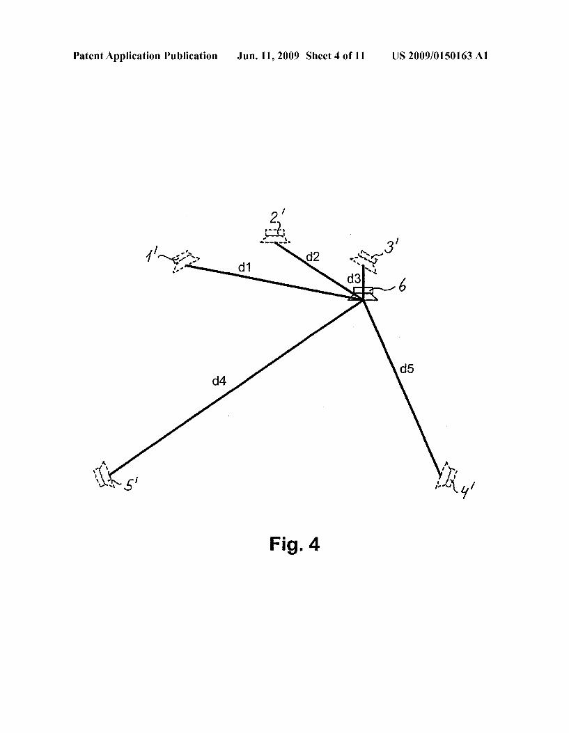
tion, there is provided a method of the above kind for indi Vidually controlling output signals (ol, o, o, . . . o.), which are to be provided to a number of pre-located real sound Sources by conversion of a set of input signals (i,i ... i.) intended for a different number and configuration of virtual Sound sources, where the pre-located real Sound sources and the virtual sound sources are located or represented in a vector space, and where each particular pre-located real Sound Source is provided with a signal (ol, o, o, . . . o.) that has a magnitude and time delay obtained as a linear Sum of at least Some of said input signals intended for the virtual Sound sources, and the magnitudes and delays of the signal (o, o, o, ... o.) to be provided to a particular one of said real Sound Sources are calculated by using the vectorial distances between each of the virtual sound sources and the particular pre-located Sound source. 0017. According to the above embodiment of the inven tion, the signal sent to a given loudspeaker is created by Summing all input channels from the playback medium with each input channel assigned an individual delay and gain. These two parameters are calculated using the relationship between the desired locations of the loudspeaker(s) and the actual location of the loudspeaker(s). For example, FIG. 4 shows the desired locations of five loudspeakers (hereafter labelled “virtual loudspeakers) for a multi channel audio reproduction system. In addition, one of the actual loudspeak ers is shown. The distance between each of the virtual loud speakers and the real loudspeaker is calculated. This can be done using an X,Y,Z coordinate system where the virtual and the real worlds are considered on the same scale using the equation:
where d is the distance between the real and virtual loud speakers, (X,Y,Z) is the location of the virtual loudspeaker in a Cartesian coordinate system, and (X, Y, Z, ) is the location of the real loudspeaker. All variables are assumed to be on the same scale.
0018. The distance between a given virtual loudspeaker and a given real loudspeaker is used to calculate again and delay corresponding to the gain and delay naturally incurred by propagation through that distance in a real environment. The delay can be calculated using the equation
g
where D is the propagation delay to be simulated, d is the calculated distance between the virtual and real loudspeakers and c is the speed of Sound in air.
Jun. 11, 2009
0019. The gain to be applied to the signal is typically attenuation, and is also determined by the distance between the real and virtual loudspeakers. As an example, this can be calculated using the equation
where g is gain applied to the signal simulating attenuation due to distance.
0020. Alternatively, the gain calculation could be based on Sound power rather than Sound pressure attenuation over dis tance.
0021. The above gain/attenuation g is independent on fre quency, but it is also possible according to the invention to apply a frequency-dependent g-function, i.e. g(f). By apply ing g(f) for instance, frequency-dependent directional char acteristics of the virtual sound sources may be accounted for, and it is furthermore possible to introduce perceptual effects of the open ear transfer function of the human ear, this func tion being generally a function of both frequency and angle of Sound incidence from the virtual sound Source to the position of the listener. An illustrative example will be given in the detailed description of the invention. In this generalised case (both relating to directional characteristics of the virtual sound sources and to the incorporation of HRTFs), the func tion g will depend on both direction of sound incidence from a given sound source to the listening position, this direction being denoted by the vector R, and on the frequency, i.e. g. as mentioned above will be replaced by (R, f). 0022. According to the invention, there is furthermore provided an apparatus for performing a conversion or upmix/ downmix operation comprising: 0023 (a) n input terminals for receiving input signals (i. i. . . . i.) from a suitable input source:
0024 (b) processing means (H. H. . . . H) for pro cessing corresponding input signals (i. i2. . . . i.), whereby each of the processing means provides a processed output signal (ol, O2 . . . On):
0025 (c) m Summing means for providing m output sig nals (ol, O2, Os. . . . On): 0026 where each of said summing means can be pro Vided with processed output signals (o, O2 . . . o.) corresponding to each of said input signals (i. i2. . . . i.).
0027. According to a specific embodiment of the appara tus according to the invention each of said processing means (H1, H2 . . . H) comprise delay means or gain means, or both delay means and gain means, whereby each of said processed output signals (o, O2, o, . . . o.) will be a delayed version of the corresponding input signal oran ampli fied or attenuated version of the corresponding input signal or a delayed and amplified or attenuated version of the corre sponding input signal. 0028. According to a specific embodiment of the Inven tion, said apparatus comprises: 0029 (a) a data register for storing location coordinate information for each of a set of pre-located loudspeakers and for each of a set of virtual loudspeakers:
0030 (b) a series of A/D converter means for receiving input signals corresponding to the virtual loudspeakers and converting them to a digital representation;
US 2009/015O163 A1
0031 (c) means for determining the numerical vectorial distance between each of the virtual loudspeakers and a particular pre-located loudspeaker,
0032 (d) means for storing said numerical vector dis tances in an intermediate result matrix;
0033 (e) division means for determining the correspond ing delays (D) by dividing the numerical vectorial distance by the speed of Sound in air (c);
0034 (f) means for determining the corresponding gains (g) by taking the reciprocal of said numerical vector dis tances,
0035 (g) multiplier means for multiplying each of said input signals by the corresponding gain (g) and adder means for adding the corresponding delay (D); and
0.036 (h) Summing means for adding the processed signals corresponding to each virtual loudspeaker to obtain a sig nal to a D/A converter, whereby an output signal (o, o, . ..o.) for each of said pre-located loudspeakers is provided.
0037. If the input source provides digital output signals, the series of A/D converter means mentioned under item (b) above can of course be omitted. Furthermore, if “digital' loudspeakers with digital amplifiers (for instance class-D amplifiers) are used, the D/A converter mentioned under item (h) above can also be omitted. 0038. The present invention furthermore relates to the use of the inventive method and apparatus for Supplying a set of automotive loudspeakers with signals corresponding to a home entertainment environment. 0039. The method and apparatus according to the inven tion can for instance be used in domestic Sound reproduction systems and automotive Sound reproduction systems. 0040. The methods can give listeners the impression that loudspeakers are correctly placed in configurations where this is not the case.
0041. The methods can be used as a matrix that translates any desired number of channels in the distribution or play back media (i.e. 2-, 5.1-, 7.1-, 10.2-channels etc. . . . ) to any number of loudspeakers. 0042. The methods can be used to minimise the apparent differences between loudspeakers in domestic, automotive Sound systems or for Sound reproduction systems in yachts. 0043. The methods can be used to produce a suggested tuning of delay and gain parameters for instance for domestic Sound systems, automotive audio systems or for Sound repro duction systems in yachts.
BRIEF DESCRIPTION OF THE DRAWINGS
0044) The present invention will be more fully understood with reference to the following detailed description of embodiments of the invention and with reference to the fig U.S.
0045 FIG.1. Example of a standard loudspeaker configu ration. This particular example is for a 5-channel system following the ITU-BS.775 recommendation. 0046 FIG. 2. Example showing the relationship between the desired loudspeaker locations (shown in dotted lines) and the actual location of one loudspeaker (Solid lines) in a lis tening environment. 0047 FIG. 3. Example showing the relationship between the two desired loudspeaker locations (shown in dotted lines) and the actual location of five loudspeakers (Solid lines) in a listening environment.
Jun. 11, 2009
0048 FIG. 4. Example of the calculation of the distances between the desired locations of the loudspeakers and the location of the real loudspeaker. 0049 FIG. 5. Example implementation of the algorithm required to generate an output for the real loudspeaker shown in FIG. 4 using the calculated distances d1 through d5. The Vertical line indicates a mixing bus where all signals arriving from the left are added and sent to the output on the right. 0050 FIG. 6. A generalised diagrammatic representation of the apparatus according to the invention for converting in input channels to m output channels. 0051 FIG.7. An embodiment of a system according to the invention used to create a two-channel downmix from a five channel source. 0.052 FIG. 8. A schematic block diagram showing the signal processing required to implement the system illus trated in FIG. 7. 0053 FIG. 9. An embodiment of the system according to the invention used as an upmix algorithm in an automotive audio system. 0054 FIG. 10. A schematic representation of an imple mentation of a system in a car using the method and apparatus according to the present invention. 0055 FIG. 11. A schematic representation of a system according to the invention comprising functions representing the differences between two head-related transfer functions.
DETAILED DESCRIPTION OF THE INVENTION
0056. The proposed system can be used as an n-to-m chan nel upmix algorithm or an n-to-m channel downmix algo rithms i.e. as an algorithm for correction of loudspeaker placement. 0057 The methods can furthermore be used as a matrix that translates any desired number of channels in the distri bution or playback media (i.e. 2-, 5.1-, 7.1-, 10.2-channels etc. . . . ) to any number of loudspeakers. 0058. The method and apparatus according to the inven tion can be regarded as a method/apparatus for reproducing a given number (n) of virtual Sound Sources (loudspeakers) by means of a different number (m) of actual physical Sound Sources (loudspeakers). Thus, for instance the standard loud speaker configuration shown in FIG. 1, i.e. a 5-channel sys tem following the ITU-BS.775 recommendation can be simu lated using the method and apparatus according to the invention. In this case, the five actual loudspeakers indicated by reference numerals 1 through 5 in FIG. 1 are regarded as corresponding virtual loudspeakers 1' through 5' as shown in FIGS. 2, 4, 7, 9 and 10 (shown in dotted lines in FIG. 2), and these virtual loudspeakers are replaced by a different number of actual physical loudspeakers, of which only one is shown in FIG. 2 indicated by reference numeral 6. If the number of actual loudspeakers is less than the number of virtual loud speakers, a downmix procedure is performed. An upmix pro cedure could consist of a replacement of two virtual loud speakers 12 and 13 being replaced by five actual loudspeakers 7, 8, 9, 10 and 11 as shown in FIG. 3. 0059. According to an embodiment of the invention the signal sent to a given loudspeaker is created by Summing all input channels from a playback medium with each input channel assigned an individual delay and gain. These two parameters are calculated using the relationship between the desired locations of the virtual loudspeaker(s) and the loca tions of the actual loudspeaker(s). For example, FIG. 4 shows the desired locations of five virtual loudspeakers 1', 2',3', 4'
US 2009/015O163 A1
and 5' for a multi channel audio reproduction system. In addition, one of the actual loudspeakers 6 is shown. The distanced through dis between each of the virtual loudspeak ers 1', 2',3', 4' and 5' and the real loudspeaker 6 is calculated. This can be done using an X,Y,Z coordinate system where the virtual and the real worlds are considered on the same scale using the equation:
where d is the distance between the real and virtual loud speakers, (X,Y,Z) is the location of the virtual loudspeaker in a Cartesian coordinate system, and (X, Y, Z, ) is the location of the real loudspeaker. All variables are assumed to be on the same scale. 0060. The distance between a given virtual loudspeaker and a given real loudspeaker is used to calculate again and delay corresponding to the gain and delay naturally incurred by propagation through that distance in a real environment. The delay can be calculated using the equation
g
where D is the propagation delay to be simulated, d is the calculated distance between the virtual and real loudspeakers and c is the speed of Sound in air. 0061 The gain to be applied to the signal is typically attenuation, and is also determined by the distance between the real and virtual loudspeakers. As an example, this can be calculated using the equation
i where g is the gain applied to the signal simulating attenua tion due to distance. 0062 An apparatus corresponding to the situation shown in FIG. 4 is shown in FIG. 5, where the signals on each of the 5 separate input channels 14, 15, 16, 17 and 18 are subjected to individually determined delays 19, 20, 21, 22 and 23 and corresponding gains 24, 25, 26, 27 and 28 determined by the above equations. The thus processed input signals are summed as indicated by 29, whereby the output signal 30 for the real loudspeaker 6 (FIG. 4) is obtained. 0063. With reference to FIG. 6 there is shown a genera lised diagrammatic representation of the apparatus according to the invention for converting n input channels to m output channels. A multi channel source, for instance a CD or DVD player 31 is providing in output signals corresponding to n channels of audio as input signals (i,i ..., ii) to a block of processing means, in the implementation shown in FIG. 6 comprising a total of nxm processing means 33, which may be defined by transfer functions (H. H. . . . H) or corre sponding impulse responses h(i). According to a specific embodiment of the invention, the processing means 33 com prises delay means 34 and gain means 35. From each of the processing means, processed output signals (o, O2, o, . . ... o.) are provided and these output signals are provided to a total of m Summing means 36, one for each output channel, i.e. real loudspeaker, for providing moutput signals 37, where the first of said summing means 36 is provided with processed
Jun. 11, 2009
output signals (o, o . . . o.) corresponding to each of said input signals (i. i2. . . . . i.), etc. 0064. With reference to FIGS. 7 and 8 there is shown an embodiment of a system according to the invention used to create a two-channel downmix from a five-channel source. The real loudspeakers 38 and 39 are placed in “incorrect” locations in a listening room. The virtual loudspeakers 1', 2', 3', 4' and 5' are each positioned in the appropriate locations in a virtual space near the real loudspeakers. Individual dis tances between the virtual loudspeakers and the real loud speakers are calculated in two or three dimensions. For example, 40 is the distance between the virtual left loud speaker 1" and the real left loudspeaker 39.41 is the distance between the virtual left loudspeaker 1" and the real right loudspeaker38. These two distances are used to determine the delay and gain of the signal from the left input channel to the left and right output channels sent to the real loudspeakers. Each input channel is assigned an appropriately calculated delay and gain for each output channel and these modified inputs are Summed and sent to each loudspeaker. 0065 Referring to FIG.8 there is shown a schematic block diagram showing the signal processing required to implement the system illustrated in FIG. 7. Each delay and gain is indi vidually calculated according to the distance relationship between the virtual loudspeakers associated with each input channel and the real loudspeakers associated with the output channels. A five-channel signal source 31 comprising five channels 32 (Left Front, Centre Front, Right Front, Left Sur round and Right Surround) delivers input signals to the cor responding delay and gain means 34, 35 and the output sig nals from these are Summed as described above in Summing busses 36, whereby the required two output signals 37 for the real loudspeakers 38 and 39 are provided. 0.066 Referring to FIG. 9 there is shown an embodiment of the system according to the invention used as an upmix algorithm in an automotive audio system. The real loudspeak ers are indicated in solid lines (42 front left tweeter, 48 front left woofer, 47 back left full-range, 43 front right tweeter, 44 front right woofer, 45—back right full range, 46—Subwoofer). The virtual loudspeakers are shown in dotted lines indicated by reference numerals 1', 2',3', 4' and 5". Each individual distance from a given virtual loudspeaker to a real loudspeaker is calculated and shown as an example for one real loudspeaker 42 as indicated by 53, 49.50, 51 and 52, respectively. These distances are calculated for all virtual loudspeaker-to-real loudspeaker pairs. 0067. With reference to FIG. 10 there is shown a sche matic representation of an implementation of a system in a car using the method and apparatus according to the present invention. The figure shows a car 54 provided with left and right loudspeakers 55, 56 for instance mounted in the left and right front doors of the car. The car is provided with a five channel playback device 59 for playback of five-channel sur round sound recorded on a suitable medium 58 such as a CD or DVD. The five output channels from the playback device 59 delivers five input signals to a downmix apparatus 60 according to the invention, and the two output channels from this apparatus are fed to the left and right loudspeakers 55 and 56, respectively. The downmix apparatus in this implemen tation thus provides a downmix from the five channels of audio delivered by the playback device 60 to the two real loudspeakers 55 and 56. By this process, the signals corre sponding to the five virtual loudspeakers 1', 2',3', 4' and 5' are provided.
US 2009/015O163 A1
0068. In order to program the apparatus, X, Y, Z coordi nates 63, 64 of the real loudspeakers 55, 56 and X, Y, Z coordinates I, II, III, IV, V of the virtual loudspeakers 1', 2',3', 4, 5 are entered by means of a suitable user interface, for instance by the touch screen device 61 schematically shown in FIG. 10. Many other interfaces are possible in a practical set-up. The coordinates of the real and/or virtual loudspeakers may be stored in storage means 68, thus facilitating re-pro gramming of the apparatus for instance if changes of the actual set-up of loudspeakers are made. The total system as shown in FIG. 10 may furthermore comprise storage means 65 for storing directional characteristics of the various real and/or virtual loudspeakers and storage means 66 for storing head-related transfer functions HRTF if such functions are to be incorporated into the method and apparatus according to the invention. Also a user-operated width control 67 (or rota tion-control as mentioned in the Summary of the invention) may be provided for the purpose described below. It is under stood that further or alternative user interfaces may be pro vided without departing from the present invention. 0069. With reference to FIG. 11 there is shown a sche matic representation of an embodiment of the method/appa ratus according to the invention comprising functions repre senting the differences between two head-related transfer functions. In order to obtain a clear perception of the virtual loudspeakers 4 and 5', which in a surround sound loud speaker set-up will be located behind the listener 71 generated by Sound reproduction from one or more loudspeakers actu ally located in front of the listener (real loudspeaker 6 in FIG. 11), differences between the HRTFs corresponding to the direction to the desired (virtual) loudspeaker and the real loudspeaker may be incorporated in the corresponding pro cessing pathways (d. and ds in FIG. 11). According to this embodiment of the invention, the perception of the sound image of the Surround loudspeakers 4 and 5' as actually being located behind the listener is enhanced by head-related cor rections AHRTF and AHRTFs applied to the corresponding gain and delay channels (69 and 70 in FIG. 8). The functions AHRTF and AHRTFs are according to this embodiment defined by the equation:
where it is assumed that the head-related transfer functions from the virtual loudspeakers 4 and 5' to the listener 71 are identical, which in principle will be true in this case, as the set-up is symmetrical with respect to the median plane through the listener 71 indicated by 72 in FIG. 11. 0070. As mentioned above in connection with FIG. 10, a “width control’ may be incorporated in the method/apparatus according to the invention. Thus, there exists the possibility of using the proposed method/apparatus to permit an end user to control the apparent “width' or “surround content of an audio presentation. This can be accomplished by altering the locations of the virtual loudspeakers using a controller 67 (FIG.10) presented to the end user. Increasing the “surround or "width' amount, could, for example, increase the angle subtended by the virtual loudspeaker and a centre line. Decreasing the “width” amount would collapse the angles such that all virtual loudspeakers would be co-located with the front centre virtual loudspeaker. Also a rotation-effect of the sound field can be accomplished as mentioned previously.
1. A method for converting n input signals to m output signals, where each of said output signals (ol, o, o, . . . o.) is obtained as the Sum of processed signals (o, O2 . . . o.),
Jun. 11, 2009
where each of said processed signals is obtained by process ing corresponding input signals (i. i2. . . . i.) in processing means having a transfer function H, or an impulse response h, and where the output signals (o, o, o, ... o.) are individually
controlled and provided to a number of pre-located real sound sources by conversion of a set of input signals (i. i. . . . i.) intended for a different number and configu ration of virtual sound sources,
characterized in that the pre-located real sound sources and the virtual Sound sources are represented in a vector space, and in that each particular pre-located real Sound Source is Supplied with a signal (ol, o, os. . . . o.) that is obtained as a linear Sum of at least Some of said input signals intended for said virtual sound sources, these signals being provided with individually determined magnitudes and delays, where the magnitudes and delays are calculated by using the vectorial distances between each of the virtual sound sources and the par ticular pre-located Sound source.
2. (canceled) 3. A method according to claim 1, where said processing in
said processing means comprises means for providing the corresponding input signals (i, i. . . . i.) with individually determined delays (D.) or individually determined gain/at tenuations (g), or both individually determined delays (D) and individually determined gain/attenuations (g).
4. A method according to claim3, wherein for each pair of virtual sound sources corresponding to a given one of said input signals (i,i ... i.) and for real Sound sources corre sponding to a given one of said output signals (i), the distance (d) between said virtual and real sound source is determined, and the corresponding gain (g) and delay (D.) are determined by application of the equations:
g-1; d. and D, d/c
where c is the speed of Sound in air. 5. A method according to claim 1, where the individual
gain/attenuations g, or transfer functions H, are functions g(f), H., of frequency (f).
6. A method according to claim 1, characterized in that the gain/attenuations and time delays are weighted according to the polar distribution of energy of each of the virtual sources, whereby the directional characteristics of the corresponding virtual sound Sources can be simulated.
7. A method according to claim 6, characterized in that the polar distribution of energy is a pre-defined Standard function applied essentially uniformly to all virtual sound sources.
8. A method according to claim 1, where the individual functions gig, (f) and D, can be varied in order to change the perceived width of the sound image produced by the real Sound Sources or to rotate this image, when these Sound Sources are provided with the output signals (ol, o, o, ... o.) obtained by application of the method of any of the preceding claims.
9. A method according to claim 1, where at least one of said functions H(f) or h(t) characterizing said processing means comprises the head-related transfer function (HRTF) of the human ear or differences between such head-related transfer functions given by the equation:
10. An apparatus for performing a conversion or upmix/ downmix operation comprising:
(a) ninput terminals for receiving input signals (i. i2. ... i.) from a suitable input source:
(b) processing means (H1, H2 . . . H) for processing corresponding input signals (i,i ... i.), whereby each of the processing means provides a processed output signal (or 1. O12 . . . On):
(c) m Summing means for providing moutput signals—(o, O2, O3. . . . On): where each of said Summing means can be provided with
processed output signals (o, O2 . . . o.) corre sponding to each of said input signals (i. i2. . . . i.);
where each of said processing means (H1, H2 . . . H.) comprise delay means or gain means or both delay means and gain means, whereby each of said processed output signals (o, O2, o, . . . o.) will be a delayed version of the corresponding input signal oran amplified or attenuated version of the corresponding input signal or a delayed and amplified or attenuated version of the corresponding input signal.
11. (canceled) 12. An apparatus according to claim 10 comprising: (a) a data register for storing location coordinate informa
tion for each of a set of pre-located loudspeakers and for each of a set of virtual loudspeakers;
(b) a series of A/D converter means for receiving input signals corresponding to the virtual loudspeakers and converting them to a digital representation;
(c) means for determining the numerical vectorial distance between each of the virtual loudspeakers and aparticular pre-located loudspeaker,
(d) means for storing said numerical vector distances in an intermediate result matrix:
(e) division means for determining the corresponding delays (D) by dividing the numerical distance by the speed of Sound in air (c);
(f) means for determining the corresponding gains (g) by taking the reciprocal of said numerical vector distances;
Jun. 11, 2009
(g) multiplier means for multiplying each of said input signals by the corresponding gain (g) and adder means for adding the corresponding delay (D); and
(h) summing means for adding the processed signals cor responding to each virtual loudspeaker to obtain a signal to a D/A converter, whereby an output signal (o, o, o, . . . o.) for each of said pre-located loudspeaker is provided.
13. An apparatus according to claim 10 comprising: (a) a data register for storing location coordinate informa
tion for each of a set of pre-located loudspeakers and for each of a set of virtual loudspeakers;
(b) means for determining the numerical vectorial distance between each of the virtual loudspeakers and a particular pre-located loudspeaker;
(c) means for storing said numerical vector distances in an intermediate result matrix:
(d) division means for determining the corresponding delays (D) by dividing the numerical distance by the speed of Sound in air (c);
(e) means for determining the corresponding gains (g) by taking the reciprocal of said numerical vector distances;
(f) multiplier means for multiplying each of said input signals by the corresponding gain (g) and adder means for adding the corresponding delay (D); and
(g) Summing means for adding the processed signals cor responding to each virtual loudspeaker to obtain an out put signal (ol, oi, o, . . . o.) for each of said pre-located loudspeaker is provided.
14. The use of a method according to claim 1 for providing a set of automotive loudspeakers or loudspeakers in a yacht with signals corresponding to a home entertainment environ ment.
15. The use of an apparatus according to claim 10 for providing a set of automotive loudspeakers or loudspeakers in a yacht with signals corresponding to a home entertainment environment.