149
IT FILE COPY CV DTIC ELEC T EiDi 0f) OC 91g987 ! u WIRE-ROPE HANDBOOK VOLLE II ON WIPE-ROPE ANALYSIS AND DESIGN DATA j hpwmd ka pubbio Mlsalft 87 I10& 083
| Date post: | 21-Oct-2015 |
| Category: |
Documents |
| Upload: | gary-j-davis |
| View: | 82 times |
| Download: | 1 times |
IT FILE COPY
CV DTICELECT EiDi
0f) OC 91g987! u
WIRE-ROPE HANDBOOK
VOLLE II
ON
WIPE-ROPE ANALYSIS ANDDESIGN DATA
j hpwmd ka pubbio Mlsalft
87 I10& 083
777-
U. S. NAVY
WIRE-ROPE HANDBOOK
VOLM1E 11
ON __________
[,cceszon For
WIRE-ROPE ANALYSIS ANDS TAB4 3
DESIGN DATA I ________-:d E
-D is t S p,.- c -sIn l a
fiNl NOUNCEDPublished by-Direction. of- Commander, Naval Sea. Systems Command
Washington, D. C.
1976
.:- 3-
Table of Contents
TABLE OF CONTENTS
Section Nuaber and Title Page
1. INTRODUCTION ................. ......................... .1-1
2. FAILURE MODES IN ROPE WIRE ....... .................. ... 2-i2.1 Mode I Fatigue Failures .......... ................... ... 2-12.2 Mode 2 Fatigue Failures .......... ................... ... 2-12.3 Tensile Failures ........... ....................... .... 2-3
3. WIRE-ROPE SYSTEM DESIGN DATA AND TECHNIQUES ... ......... ... 3-13.1. Wire-Rope Bending Fatigue Data ........... ................ 3-13.1.1. Types of Wire-Rope Bending ............ ................ 3-33.1.2. Stresses Induced by Bending Around a Sheave . . . ..... ... 3-33.1.3. Effects of Sheave-to-Rope Diameter Ratio, D/d ......... ... 3-33.1.4. Effects of Rope Load .......... ........... ....... ... 3-53.1.5. Correlation of Load and D/d Ratio With Rope Life ... ..... 3-83.1.6. Effect of Wrap Angle .......... ................... ... 3-103.1.7. Effect of Fleet Angle ....... ................... .... 3-133.1.8. Effect of Rope Material ....... .................. ... 3-133.1.8.1. Wire Type ............ ....................... .... 3-133.1.8.2. Wire Strength ... ......... . ...... .......... .. .. 3-13
3.1.9. Effects of Swivels ............ ............ ....... .. 3-153.1.10. Effects of Rope Construction ...... ........ ...... ... 3-153.1.10.1. Lay ................ ........................ . . ... 3-153.1.10.2. Number of Strands ........ . .. 3-153.1.10.3. Arrangement and Size of Wives .......... ............. 3-183.1.10.4. Preforming. .............. ....................... 3-183.1.10.5. Core ..................... .......................... 3-183.1.10.6. Special Constructions ..... ...... ........... .... 3-183.1.11. Effect of Sheave Hardness ...... ................. .... 3-183.1.12. Effects of Sheave Throat Shape .............. 3-243.1.13. Effects of Corrosion, Lubrication, and Coatings ...... .... 3-263.1.13.1. Corrosion ............ ....................... .... 3-263.1.13.2. Lubrication. ...................... 3-283.1.13.3. Coatings .............................................. 3-283.1.14. Effect of Reversed Bends ...... ................. .... 3-303.2. Axial Fatigue of Wire Rope ....... ..................... 3-333.2.1. Effect of Cyclic Axial Loads on Wire Rope Fatigue ........ 3-333.2.2. Effect of Cyclic Axisl Loads on Steel Strand Fatigue . . .3-333.2.3. Effects of End Fittings ............. .................. 3-363.2.4. Effects of Core ........... ...................... ... 3-363.2.5. Effects of Lay ...................... 3-363.2.6. Effects of Rope Construction and Material.. .......... .... 3-373.2.7. Effect of Frequency ......... .................... ... 3-373.2.8. Effect of Corrosion ......... .................... ... 3-393.2.9. Effect of Diameter .... .................... 3-393.2.10. Effects of Lubrication and Coating . ............ 3-403.3. Rotation and Torque ............ ..................... ... 3-403.3.1. Kink Formation .............. ...................... ... 3-403.3.2. Breaking Strength ............... ..................... 3-42
"" .. .
Table of Contents
Section Number and Title (Continued) Page
3.3.3. Torque CaltulicLon ........ .. ..... ............ ... 3-433.3.3.1. General Theory for Analy. - of Wire-Rope Torque . . 3-453.3.3.2. Simplified Equations for Wire Ropes With Single-
Operation Strands ....... ................. ... 3-493.3.3.3. Simplified Equations Applied to Six-Strand Wire
Ropes ............. ............. ......... ... 3-513.3.3.4. Sample Calculations for Simple Wire Rope . ....... ... 3-533.3.3.5. Measurement of Rope Lay and Strand Lay .......... ... 3-543.4. Relative Strand Motion in a Wire Rope on a Sheave ..... .. 3-553.4.1. Graphical Results of Strand-Motion Solution ......... ... 3-563.4.2. Discussion and Further Implications of the Strand-Motion
Solution ............. ....................... ... 3-563.4.3. Relative Motion of the Wires in the Strands ......... ... 3-61
4. WIRE ROPE STRESS ANALYSIS ....... ................. ... 4-14.1. Tensile Stress .............. ................. ..... ... 4-14.2. Bending Stress ............ ....................... .... 4-24.2.1. Analysis of a Straight-Wire Rope .... ............ .. 4-24.2.1.1. Wire-Rope Geometry ........ .................. ... 4-24.2.1.2. Derivation of Equations ...... ............... ... 4-64.2.1.2.1. Constant Angle Assumption .... ............. .... 4-74.2.1.2.2. Uniform-Motion Assumption . . ...- ......... .... 4-84.2.1.3. Results ............. ....................... ... 4-94.2.2. Analysis of a Wire Rope Wrapped on a Sheave ......... ... 4-164.2.2.1. Wire-Rope Geometry . . . . . .. I. . .. . ........ 4-164.2.2.2. Derivation of Equations ........... ............... 4-204.2.2.3. Results ......... ............................ 4-224.2.3. Analysis of Bending Stress ........... ............... 4-244.2.3.1. Derivation of Equations ........... ............... 4-244.2.3.2. Results ............. ....................... ... 4-284.3. Contact Stresses ............ ...................... ... 4-294.3.1. Wire-Sheave Interface ...... .................. .... 4-294.3.2. Wire Interfaces in a Strand .......... ............... 4-304.3.3. Interstrand Wire Contact ....... .......... ...... ... 4-314.3.4. Interstrand Contact Forces ........... ............... 4-324.3.5. Interstrand Contact Stresses ........... .............. 4-334.3.6. Core-Strand Interface Stresses ........... ............. 4-344.3.7. Elastic-Plastic Analysis ............. . . 4-344.4. Torsional and Shear Stresses ..... ................ .... 4-344.5. Wire Rope Dynamics ... ......... . ..... ........... .... 4-344.5.1. Longitudinal Forces ................ ................... 4-354.5.2. Transverse Forces .......... .................... ... 4-364.5.2.1. Strumming . ............ ...................... ... 4-364.5.2.1.1. Increased Drag Due to Strumning ............. ... 4-384.5.2.1.2. Strumming Suppression ..... ........... . . . . 4-384.5.2.3. Aircraft Arresting-Gear Cable .... ............ .. 4-38
5. APPENDIX ...................... .......................... 5-15.1. Rotation and Translation of Coordinates With Matrices . . . 5-15.2. Derivation of Reference Angle Relationship in Straight Rope. 5-25.3. Radius of Curvature Equations-Straight Rope Analysis . . . 5-3
-. " , -""V• -o ,.
Table of Contents
Section Number and Title (Continued) Page
5.4. Computer Programs ......... ..... ..................... 5-45.5. Derivation of Geometrical Derivatives for the kope Bent on
a Sheave .................... ......... 5-75.6. Bending-Stress Analysis Computer Program ............. ... 5-9
6. REFERENCES ........ ....... .... ............... .... .... 6-1
7. ALPHABETICAL INDEX ......... ...................... .... 7-1
- " •... t
iii.

List of Figures
LIST OF FIGURES (
Figure Number and Title Page
2-1. Initiation Site and Orientation of Mode 1 Fatigue Failures inStrand Outer Wires .......... .................... ... 2-2
2-2. Typical Mode 1 Fatigue Failure ..... ............... .... 2-22-3. Initiation Site and Orientation of Mode 1 Fatigue Failures in
Strand Inner Wires .......... .................... ... 2-22-4. Initiation Site and Orientation of Mode 2 Fatigue Failures in
Strand Outer Wires . .. ......... ................. .... 2-42-5. Initiation Site and Orientation of Mode 2 Fatigue Failures in
Strand Inner Wires .......... .................... ... 2-42-6. Typical Mode 2 Fatigue Failure (Final Failure in Tension). 2-52-7. Typical Mode 2 Fatigue Failure (Final Failure in Shear). . 2-52-8. Typical Longitudinal Split in Fatigue-Cracked Wire ... ..... 2-62-9. Initiation Site and Orientation of Mode 2 Fatigue Failures in
Strand Outer Wires .......... .................... ... 2-62-10. Typical Mode 2 Fatigue Cracks at the Points of Interstrand
Notching .............. ......................... .... 2-72-11. Typical Mode 2 Fatigue Failure ..... ............... .... 2-72-12. Initiation Site and Orientation of Mode 2 Fatigue Failures in
Strand Outer Wires .......... .................... ... 2-82-13. Typical Mode 2 Fatigue.Failure ..... ............... .... 2-82-14. Typical Mode 1 Tensile Failure .... .......... ..... . . 2-92-15. Typical Mode 2 Tensile Failure .......... ........... .. 2-9 (
3-1. Results of Bending-Fatigue Experiments Completed in VariousLaboratories .. ............ ..................... .... 3-2
3-2. Comparison of Bending-Fatigue Data Generated in DifferentLaboratories on Similar Machines ........ ............. 3-2
3-3. Types of Wire Rope Bending. ...... ................. .... 3-43-4. Effect of D/d Ratio on the Bending-Fatigue Life of lWRC
Wire Rope at Three Load Levels .......... .............. 3-43-5. Effect of D/d Ratio on the Bending-Fatigue Life of Fiber-
Core Wire Rope at Two Load Levels ......... ............ 3-63-6. Wire Rope Bending-Fatigue Results Expressed in Terms of
Rope Tension and D/d Ratio ..... ................ .... 3-63-7. Results of Bending-Fatigue Tests on 3/4-Inch Wire Rope . . . 3-73-8. Bending-Fatigue Data for a Wide Range of Loads and D/d
Ratios ...................... .......................... 3-7
3-9. Comparison of Bending-Fatigue Data on the Basis of BearingPressure Ratio .......... .......................... 3
3-10. Eighty Percent Confidence Bands for Selected BendingFatigue Data ........... ........................ 39
3-11. Bending Cycles to Failure Versus Life Factor, y .......... 3-113-12. Effect of Wrap Angle on Wire Rope Bending-Fatigue Life . • 3-113-13. Relative Wire Breakage as a Function of Wrap
Angle ............... .......................... .... 3-12
3-14. Tensile Strengths of Carbon-Steel Rope Wire as a Functionof Diameter and Wire Grade ..... ................ .... 3-12
iv

List of Figures
Figure Number and Title (Continued) Page
S3-15. Effect of Wire Strength on Bending Cycles to Failure--AllTests Completed at Equal Rope Tensions ...... .... ... 3-14
3-16. Effect of Wire Strength on Bending Cycles to Failure--AllTests Completed at Equal Design Factors .. ........ .. 3-14
3-17. Effect of Rope Lay on Bending-Fatigue Life for DifferentGroove Shapes ......... ..................... ... 3-16
3-18. Effect of Rope Construction and Rope Load on Fatigue Life. 3-173-19. Comparative Reverse-Bend Fatigue Resistance of 6 x 19 and
6 x 37 Wire Rope ........ .................... ... 3-193-20. Effect of Design Factor on Bending-Fatigue Life ..... .. 3-193-21. Effect of D/d Ratio on Bending-Fatigue Life ....... .. 3-203-22. Bending-Fatigue-Life Data for Preformed and Nonpreformed
Wire Rope Under Various Tensile Loads .. ......... .. 3-203-23. Comparison of Bending-Fatigue Data for 3/4-Inch Wire Rope
With Several Core Types, D/d = 25, df = 3 .... ....... 3-213-24. Comparison of Bending-Fatigue Data for 3/4-Inch Wire Rope
With Several Core Types, D/d = 15, df = 8 ....... .. 3-213-25. Comparison of Bending-Fatigue Data for 3/4-Inch Wire Rope
With Two Rope Core Types, D/d = 25, df = 8 ....... .... 3-223-26. Results of Bending-Fatigue Tests on Aluminum and Hardened
Steel Sheaves ........... ..................... ... 3-233-27. Effects of Sheave Material on Bending-Fatigue Life . . .. 3-243-28. Comparison of Bending-Fatigue Resistance of Several Rope
Constructions on Nylon-Lined and Cast-Iron Sheaves . . . 3-253-29. Comparison of Bending-Fatigue Resistance of Corroded and
Uncorroded Wire Rope ...... .................. ... 3-263-30. Effect of Lubrication on the Bending-Fatigue Life of a
Rope for Various Design Factors .... ...... ..... 3-293-31. Comparison of Bending Endurance of Wire Ropes Made From
Bright (Uncoated) and Drawn Galvanized Wire ...... .. 3-293-32. Comparison of Bending EndtTance of Various Galvanized Wire
Ropes ............... ........................ .. 3-313-33. Bending-Fatigue Data for Uncoated and Nylon-Jacketed Cable 3-313-34. Effect of Plain and Reverse Bending on the Fatigue Life
of Regular-Lay Wire Rope ..... ................ ... 3-323-35. Effect of Plain ard Reverse Bending on the Fatigue Life of
Lang-Lay Wirz Rope ...... ................... .... 3-323-36. Charscae-istics of Load Cycle Pattern Used in Axial Fatigue
Tests ............................. 3-333-37. Axial Fatigue Test Data fo' i-Ineh Diameter 6 x 25 Poly-
propylene Core and I.5RC, bright Improved Plow Steel,Wire Rope ..................... ....................... 3-34
3-38. Effect of Mean Lead or. the A.•tal Fatigue of IWRC andPolypropylene Corte gira Rope ..... .............. ... 3-34
3-39. Effect of Maximum, Mean and Range of Load on the AxialFatigue Life of l-Inch, 1 x 19 Galvanized Strand . . .. 3-35
3-40. Effect of Construction and Socketing Technique on theAxial Fatigue Life of Steel Strand ... ........... ... 3-36
3-41. Effect of Diameter, Core Material, Construction and Socket-ing Technique on the Axial Fatigue Life of Steel WireRope ....................... .......................... 3-37
Srv
List of Figures
Figure Number and Title (Continued) Page
3-42. Effect of Wire Strength on the Axial Fatigue Behavior of a )Steel Wire Rope (Unknown Construction) ........... .... 3-39
3-43. Effect of Wire Coating and Lubrication on the Axial Fat-igue Life of 3/4-Inch, 1 x 37 Steel Wire Strand . . .. 3-40
3-44. Typical Torque Characteristics of 18 x 7 NonrotatingWire Rope ..................... ....................... 3-43
3-45. Typical Rotational Characteristics of 18 x 7 NonrotatingWire Rope ................... ....................... 3-43
3-46. Geometry of a 6-Strand Wire Rope .... ............. .... 3-453-47. Wire Rope Force Triangle ......... ................. 3-453-48. Force Contributing to Wire Rope Torque ............. ... 3-453-40. Strand Force Triangle ..... ....... .................. 3-473-50. One Layer of Wires in a Strand ..... .......... . . . . 3-483-51. Torque Developed by Helically-Wrapped Strands in a 6-Strand
Wire Rope .. ....................... 3-513-52. Total Torque Developed by Helically Wrapped Wires in a
Single-Operation Strand of a 6-Strand Wire Rope . . .. 3-513-53. Cross Section of a 6 x 31 Fiber-Core Wire Rope ...... ... 3-523-54. Relative Strand Motion Between Nodal Planes in a Wire Rope
Wrapped on a Sheave ....... .................. ... 3-563-55. Influence of Rope and Sheave Geometry on the Relative
Strand Motion of a 6-Strand Wire Rope ..... ......... 3-573-56. SchemaLic Illustration of Nodal Angle on a Sheave . . .. 3-58
4-1. Typical Lang-Lay Wire Rope Construction ........... .... 4-44-2. Straight-Rope Geometry ...... .................. .... 4-54-3. Reference-Angle Relationship Assuming Constant Wire Lay
Angle, a . .......... ... ......................... 4-84-4. Variation in Wire Lay Angle, c, in a Straight Wire Rope
Assuming Uniform Wire Motion .... .............. .... 4-94-5. Variation in Wire Radius of Curvature Within a Wire Rope . 4-104-6. Plane Section of a 6 x 25 Filler-Wire Strand ....... .... 4-114-7. Illustration of Wire position in the Standard Rope Rela-
tive to the Z1 - Z. Coordinate System ..... ......... 4-124-8. Illustration of the Interrelationship Between Strand Lay
Angle and Strand Length as Compared to Rope Length . . . 4-144-9. Relationship Between Wire Lay Angle and the Constant of
Motion ...... ...... .. ......................... 4-154-10. Sensitivity of Radius of Curvature to Wire Lay Angle -
Constant Angle Assumption ..... ..... ............... 4-174-11. Sensitivity of Radius of Curvature to Constant of Notion -
Uniform-Motion Assumption ..... ..... ......... ... 4-184-12. Geometry of a Wire Rope Wrapped on a Sheave ......... ... 4-194-13. Radius of Curvature of Wires in a Rope Wrapped on a Sheave 4-234-14. Plane Section of a Rope Wrapped on a Sheave ......... ... 4-234-15. Illustration of Wire Segments in Complex Bending ........ 4-254-16. Coordinate Alignment Used for Comparing Radii-of-Curvature
Results ..... ..... ........................ .... 4-274-17. Bending Stress in Rope Wires Resulting From Bending of the
Standard Rope Around a 24-Inch Diameter Sheave . . .. 4-284-18. Strumning Drag Characteristics ..... .............. .... 4-395-1. Cartesian Coordinates--Common Origin; Arbitrary Orientation 5-1
vi

List of Tables
LIST OF TABLES
Table Number and Title Page
3-1. Results of Endurance Life Tests on 3/4-Inch Diameter
Aluminum Coated and Galvanized Improved Plow Steel
Wire Ropes 6 x 19--Fiber Core ........ ............ 3-27
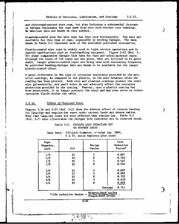
3-2. Fatigue Life Reduction Due to Reverse Bends ...... ... 3-30
3-3. Results of Cyclic Tension Tests ........ ............ 3-38
3-4. Torsional Characteristics of Various Constructions . - 3-41
3-5. Influence of Rotation on Ultimate Strength of l-k-Inch.
18 x 7 Nonrotating Wire Rope ... ............ ... 3-42
3-6. Measurements and Calculations for Example Wire-Rope
Construction . . .. ....... ..... ...................
4-1. Comparison of Bending Stress Fo~mulas ...... ......... 4-3
4-2. Cyclic Impact Test Data .............. .. •. -. " .4-36
vii

List of Symbols
LIST OF SYMBOLS )
A cross-sectional area, in2
, also constant in bending stress andcontact stress analyses
Ac area of core wire, in'
Ai area of individual wires in layer i, in2
Am metallic rope area, in2
A. area of wire n, in2
a constant in bending stress analysig
B bearing pressure ratio, also constant in contact stress analysis
b semiminor axis of ellipse formed by cross-wire contact, in, alsoconstant in bending stress analysis
C constant based on strand lay length, cos 9'/cos 9
Cb constant in contact stress analysis
CD drag coefficient for stationary cable
Cos drag coefficient for strumming cable
CG constant in contact stress analysis
Czs constant in contact stress analysis
C constant in contact stress analysis
C1. constant in contact stress analysis
c subscript denoting core of strand or rope, also constant inbending stress analysis
D pitch diameter of sheave, in
d rope diameter, in
df design factor, ratio of new rope breakinj strength to design load
1o -- diameter of outside wire in a strand
d s strand diameter, in
Sdw wire diameter, in
viii

List uf Symbols
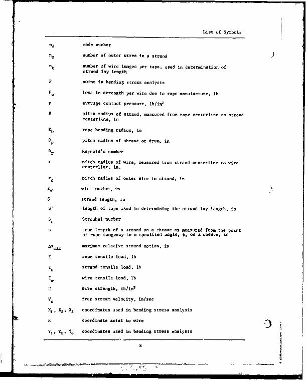
nf mode number
no number of outer wires in a strand
nt number of wire images per tape, used in determination ofstrand lay length
P point in bending stress analysis
Po loss in strength per wire due to rope sanufacture, lb
p average contact pressure, lb/in2
R pitch radius of strand, measured from rope centerline to strandcenterline, in
R b rope bending radius, in
Rp pitch radius of sheave or drum, in
Rr Reynold's number
r pitch radius of wire, measured from strand centerline to wirecenterline, in.
ro pitch radius of outer wire in strand, ir.
r. wir3 radius, in
S strand length, in
S, length of tape •sed in determining the strand lay length, in
S Strouhal numbers
s true length of a strand on a rbeave as measured from the pointof rope tangenzy to a specifie-l angle, *, on a sheave, in
ASmax maximum relative strand motion, in
T rope tensile load, lb
T strand tensile load, lbs
T wire tensile load, lb
wire strength, lb/in2
Vo free stream velotity, in/sec
Xv ,Y2 X3 coordinates used in bending stress analysis
x coordinate axial to wire
Y1 , Y2 . Y3 coordinates used in bending stress analysis
x
List uf Symbols
nf mode number
no number of outer wires in a strand
nt number of wire images per tape, used in determination ofstrand lay length
P point in bending stress analysis
Po loss in strength per wire due to rope sanufacture, lb
p average contact pressure, lb/in2
R pitch radius of strand, measured from rope centerline to strandcenterline, in
R b rope bending radius, in
Rp pitch radius of sheave or drum, in
Rr Reynold's number
r pitch radius of wire, measured from strand centerline to wirecenterline, in.
ro pitch radius of outer wire in strand, ir.
r. wir3 radius, in
S strand length, in
S, length of tape •sed in determining the strand lay length, in
S Strouhal numbers
s true length of a strand on a rbeave as measured from the pointof rope tangenzy to a specifie-l angle, *, on a sheave, in
ASmax maximum relative strand motion, in
T rope tensile load, lb
T strand tensile load, lbs
T wire tensile load, lb
wire strength, lb/in2
Vo free stream velotity, in/sec
Xv ,Y2 X3 coordinates used in bending stress analysis
x coordinate axial to wire
Y1 , Y2 . Y3 coordinates used in bending stress analysis
x

List of Symbols
y coordinate tangential to wire
( Z, Z2 , Z3 coordinates used in bending stress analysis
Zs distance between wire surface and location of Tmax and rGmax' in
z coordinate radial to wire
& wire lay angle, degrees (positive for right-hand lay)
O'n lay angle of wire n, degrees
C•o lay angle of outer wires in a strand, degrees
8 strand lay angle, degrees (positive for right-hand lay)
8' lay angle of a strand in a rope, measured between rope centerlineand outer diameter, degrees
y life factor
Yo complement of angle between individual wire and centerline of rope,degrees
A constant in contact stress analysis
6 angle in bending stress analysis, degrees
C strain, in/in
e angle defining the position of a strand in a wire rope, degrees
9c wire crossing angle, degrees
90 initial angular position of a strand, degrees
X general lay angle, degrees
Poisson's ratio
F difference between two wire radii of curvature, in
0 radius of curvature of wire, in
a tensile stress in a wire, lb/inc
ab bending stress in a wire, lb/in2
cc tensile stress in a core wire, lb/ina
Cmax maximum tensile stress, lb/in2
Sn tensile stress in wire n, lb/in2
xi

List of Symbols
X shear stress, lb/in2 9
Xsmax maximum octahedral shear stress, lb/in2
Ymax maximum shear stress, lb/in2
O angle defining position of a wire in a strand, degrees
0' first derivative of 0 with respect to e
second derivative of 0 with respect to 0
* sheave reference angle, degrees
*n nodal angle, degrees
CA angle between flow direction and cable axis, degrees
single-bend wire rope fatigue data (Europein notation)
reverse-bend wire rope fatigue data (European notation)
xii i
• - • • _•=- -• , _-• ' ,C ...
Introduction 1.
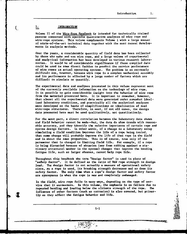
i~L___ INTRODUCTION
Volume II of the Wire-Rope Handbook is intended for technically trainedpersons concerned with specific quantitative analyses of wire rope andwire-rope systems. This volume complements Volume 1 with a large amountof state-of-the-art technical data together with the most recent develop-ments in analysis methods.
Over the years, a considerable quantity of field data has been collectedby those who make and use wire rope, and a large volume of experimentaland analytical information has been developed in various research labora-tories. It would be of considerable significance if these compiled datacould be used in some direct fashion to predict the service performanceof wire ropes in actual operating systems. The problem is an extremelydifficult one, however, because wire rope is a complex mechanical assemblyand its performance is affected by a large number of factors which aredifficult to simulate or quantify.
The experimental data and analyses presented in this volume represent mostof the currently available information on the technology of wire rope.It is possible to gain considerable insight into the behavior of wire ropefrom the material presented here. It is important to remember, however,that almost all the experimental data were generated under somewhat ideal-ized laboratory conditions, and practically all the analytical analyseswere developed on the basis of simplifications or idealization of realwire-rope structures. Therefore, in most, if not all cases, the designdata presented here must be used qualitatively, not quantitatively.
For the most part, a direct correlation between the laboratory data shownand field behavior cannot be made--but, the data do show trends with reason-able accuracy, and they identify the relative importance of certain rope andsystem design factors. In other words, if a change in a laboratory setupsimulating a field condition improves the life of a rope being tested,that same change will probably improve the life of that rope in the fieldand in about the same proportion. This is of course, true only if theparameter that is changed is limiting field life. For example, if a ropeis being discarded because of abrasion (say from rubbing against a sta-tionary structural member in the system) changes that improve the bendingfatigue life, such as larger sheaves, cannot help rope life.
Throughout this handbook the term "design factor" is used in place of"safety factor". It is defined as the ratio of NEW rope strength to designload. The design factor is not actually a measure of operational safetysince, as a rope is used, its breaking strength decreases and so does itssafety factor. The only time when a rope's design factor and safety factorare synonymous is when the rope is new and completely undamaged.
In the field, wire rope fails in many ways, depending on the type of ser-vice that it encounters. In this volume, the emphasis is on failure due torepeated bending and loading below the ultimate strength of the rope. Theinfluence of other factors (such as corrosion) is also covered, but primar-ily as they affect the fatigue behavior and life.
1-1
_o
Failure Modes in Rope Wire 2.
S2. FAURE ODS IN ROPS WIRE
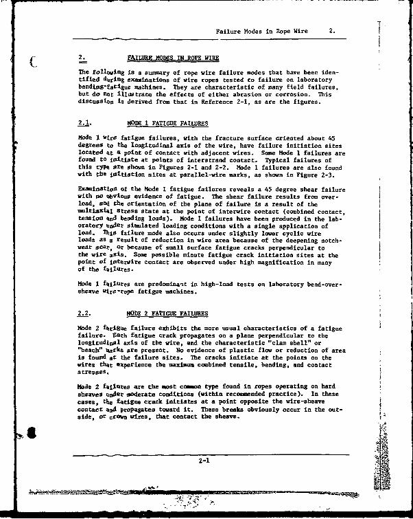
The following is a sum-ary of rope wire failure modes that have been iden-tified during examinations of wire ropes tested to failure on laboratorybending-facigue mazhines. They are characteristic of many field failures,but do not illustrate the effects of either abrasion or corrosion. Thisdiscussion is derived from that in Reference 2-1, as are the figures.
2.1. MODE 1 FATIGUE FAILURES
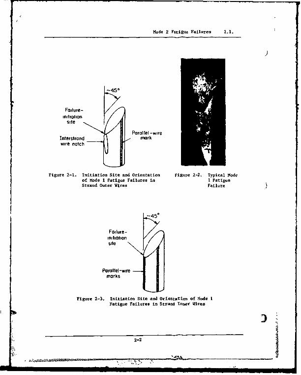
Mode 1 wire fatigue failures, with the fracture surface criented about 45degrees to the longitudinal axis of the wire, have failure initiation siteslocated at a point of contact with adjacent wires. Some Mode 1 failures arefound to initiate at points of interstrand contact. Typical failures ofthis type Are shown in Figures 2-1 and 2-2. Mode 1 failures are also foundwith the iiltiation sites at parallel-wire marks, as shown in Figure 2-3.
Exami atioa of the Mode 1 fatigue failures reveals a 45 degree shear failurewith no obvious evidence of fatigue. The shear failure results from over-load, and the orientation of the plane of failure is a result of themultiaxial stress state at the point of interwire contact (combined contact,tension and bending loads). Mode 1 failures have been produced in the lab-oratory under simulated loading conditions with a single application ofload. This failure mode also occurs under slightly lower cyclic wireloads as a result of reduction in wire area because of the deepening notch-wear scat, Or because of small surface fatigue cracks perpendicular tothe wire axis. Some possible minute fatigue crack initiation sites at thepoint of interwire contact are observed under high magnification in manyof the failures.
Mode I failures are predominant in high-load tests on laboratory bend-over-sheave wire-rope fatigue machines.
2.2. MODE 2 FATIGUE FAILURES
Mode 2 fatigue failure exhibits the more usual characteristics of a fatiguefailure. Fach fatigue crack propagates on a plane perpendicular to thelongitudinal axis of the wire, and the characteristic "clam shell" or"beach" %arks are present. No evidence of plastic flow or reduction of areais found at the failure sites. The cracks initiate at the points on thewires that experience the maximum combined tensile, bending, and contactstresses.
Made 2 failures are the most common type found in ropes operating on hardsheaves under moderate conditions (within recommended practice). In thesecases, the fatigue crack initiates at a point opposite the wire-sheavecontact and propagates toward it. These breaks obviously occur in the out-side, or crown wires, that contact the sheave.
2-1
Mode 2 Fatigue Failures 2.1.
)
-45°
Failure-initiation
site
"Parallel -wireInterstrand ,_ markwire notch
Figure 2-1. Initiation Site and Orientation Figure 2-2. Typical Modeof Mode 1 Fatigue Failures in I FatigueStrand Outer Wires Failure
-450
Failure-initiationsite
Parallel-wiremarks
Figure 2-3. Initiation Site and Orientation of Iode 1Fatigue Failures in Strand Inner Wirea
2-2

Mlode 2 Fiatigue Failures 2.2.
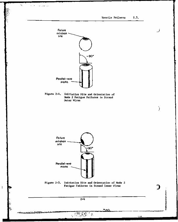
Failures of this type are found to initiate on the as-drawn surface ofthe wires in areas not associated with points of interwire contact. On( aluminum sheaves, these fatigue cracks appear on the outer surface of thewire rope well away from points of interstrand contact. This type offailure is illustrated in Figure 2-4. The inner wires of the strandsoften display a similar type of failure, with the fatigue crack initiatingbetween two parallel-wire marks as illustrated in Figure 2-5. Both ofthese Mode 2 fatigue failures are found after low-load tests on laboratoryfatigue machines.
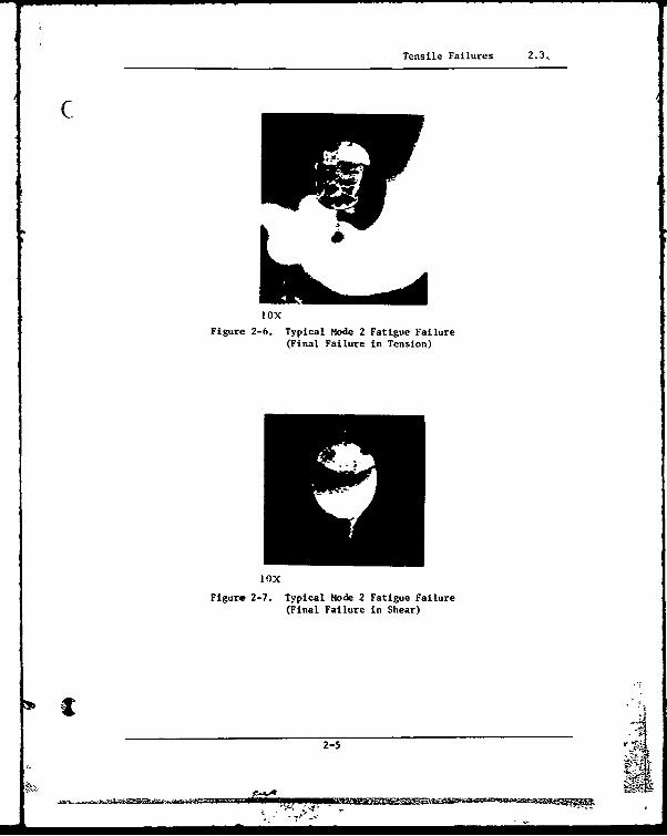
For many Mode 2 failures, each fatigue crack propagates into the wire untilthe reduction in metallic area and the stress concentration at the crackroot result in complete fracture. The lower the tensile load on thespecimen, the further the cracks propagate. Final failure may then beeither a tensile-type failure displaying a rather rough fracture surfaceapproximately perpendicular to the wire axis, or a shear-type failure dis-playing a rather smooth fracture surface about 45 degrees to the wire axis.Examples of each of these failures are shown in Figures 2-6 and 2-7. Some-times a Mode 2 failure is accompanied by a longitudinal splitting of thewire as shown in Figure 2-8. This wire splitting occurs more frequentlyat the lower test loads.
Another type of Mode 2 fatigue failure has been identified in wire-ropespecimens where there is severe interwire notching. For these failuresthe fatigue cracks are found to initiate at the edge of a wire notch formedby interstrand contact as shown in Figure 2-9. Photographs of typicalwires displaying this failure mode are shown in Figures 2-10 and 2-11.
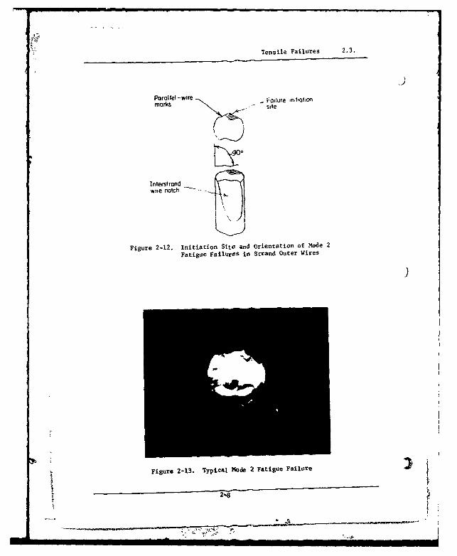
Mode 2 fatigue cracks can also initiate on the side of the wire oppositethe notch at or near the parallel-wire marks and propagate toward thenotch. Examples of these failures are shown in Figures 2-12 and 2-13.
2.3. TENSILE FAILURES
During any type of wire-rope fatigue test, the wires begin to fail by oneof the above-mentioned fatigue modes. The strength of the rope is grad-ually reduced until complete failure of a strand or strands results fromtensile overload of the remaining wires. Some of these tensile failuresdisplay a standard cup-cone type of failure.
The fracture surface of the cup-cone tensile failure is symnetrical andexhibits large shear lips around the outer edge of the wire and creates thetypical "cup" and "cone" as shown in Figure 2-14. The no.minal orientationof the fracture surface is perpendicular to the longitudinal axis cf thewire, and a large reduction of cross-sectional area is found at the fracturelocation. Failures of this type are typical of low-strain-rate round-bartensile failures of a ductilejgaJerial.
2-3
Tensile Failures 2.3.
Failure _initiationsite
Parallel-wiremarks ~-J
Figure 2-4. Initiation Site and Orientation ofMode 2 Fatigue Failures in StrandOuter Wires
Failureinitiation
site
Parallel-wiremarks
Figure 2-5. Initiation Site and Orientation of Mode 2Fatigue Failures in Strand Inner Wires
2-4
I I I I I II I I I I i I
Tensile Failures 2.3.
loxFigure 2-6. Typical Mode 2 Fatigue Failure
(Final Failure in Tension)
lox
Figure 2-7. Typical Mode 2 Fatigue Failure(Final Failure in Shear)
2-5 r
ME
Tensile Failures 2.3.
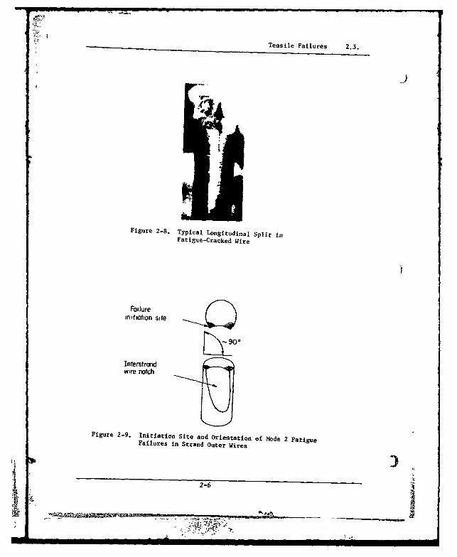
Figure 2-8. Typical Longitudinal Split inFatigue-Cracked Wire
Failureinitiation site
Interstrondwire notch
Figure 2-9. Initiation Site and Orientation of Mode 2 FatigueFailures in Strand Outer Wires
2-32-6
- i
-- H2

Tensile Failures 2.3.
Figure 2-10. Typical Mode 2 Fatigue Cracks at the Pointsof Interstrand Notching
Figure 2-11. Typical Mode 2 Fatigue Failure
2-7
Tensile Failures 2.3.
Parallel -wire Failure intiotiOfimarks - site
Interstrand ._ _wile nolch
Figure 2-12. Initiation Site and Orientation of Mode 2
Fatigue FailureS in Strand Outer Wires
Figure 2-13. Typical Made 2 Fatigue Failure
N-84
i 1'! '* 2(
Tensile Failures 2.3.
I2X
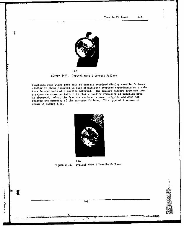
Figure 2-14. Typical Mode 1 Tensile Failure
Sometimes rope wires that fail by tensile overload display tensile failures
similar to those observed in high strain-rate overload experiments on simple
tensile specimens of a ductile material, The failure differs from the low-
strain-rate cup-cone failure in that a smaller reduction of metallic area
is observed. Also, the fracture surface is more irregular and does not
possess the symmetry of the cup-cone failure. This type of fracture is
shown in Figure 2-15.
IzX
Figure 2-15. Typical Mode 2 Tensile failure
It
2-9
ENO"
Wire-Rope System Design Data and Techniques 3.
3. WIRE-ROPE SYSTI4 DESIGN DATA AND TECHNIQUES
3.1. Wire-Rope Bending Fatigue Data
The primary reason for the retirement of a rope from service in most runningrigging is fatigue from bending around sheaves. (Running rigging is thatin which the rope moves, such as a crane-hoist rope, whereas in standingrigging the rope is stationary and usually straight as in tower guys.)Before discussing the effects of specific system parameters, certain generalfacts concerning the data and its use should be noted.
The data should be used qualitatively, not quantitatively. Generally, thelife of a rope in the field will be longer than it is in a laboratory experi-ment. The reasons for this are not precisely known, but it can be speculatedthat rope in the field tends to rotate on its axis as it runs through thesystem, thus distributing fatigue damage around the circumference of therope, Most laboratory bending.fatigue machines restrain the rope from rota-tion, thus confining the fatigue damage to one part of the rope circumference.Also, in most field situations, the rope is subjected to a variety of loads.It is normal engineering practice to consider the highest of these as thedesign load and to use this to compare field life to laboratory life. Thus,the field conditions are actually less severe in many cases than the labora-tory imposed loading conditions.
Laboratory data from experiments conducted some time age are usually quiteconservative for modern ropes. Comparison of bending fatigue data from upto 50 years ago clearly shows that the relative life has significantlyimproved. Again, the reasons for this are not well defined but probably aredue to a number of improvements in both wire quality and rope fabricationtechniques. The development of preforming in particular has extended ropebending-fatigue life. In this Volume, an effort has been made to use moderndata. However, in some cases, particularly where the data are not of domes-tic origin, the vintage is unknown.
When attempting to apply laboratory data to a field system, particular atten-tion must be given to the wire failure modes as discussed in the previoussection. The data will probably not be applicable, even qualitatively,unless the failure modes are the same as those found in the laboratory.
This is generally not a problem if the operating conditions are fairly wellsimulated.
Laboratory bending fatigue data generated by different laboratories are notnecessarily comparable. Figure 3-1 shows the results of a program recentlyconducted by the International Organization for the Study of the Enduranceof Wire Rope (Refs, 3-1 and 3-2). This organization sent samples of & parti-cular size and typn of wire rope to a number of their members to run bending-fatigue tests under identical conditions of sheave geometry and load. Thefatigue machines used were, however, quite diverse in configuration andoperating principles. The numerical variation in the data from one labors-tory to another is obvious. However, note that the trends are similar andmost of the line slopes are about equal.
3-1SN I

Wire-Rope Bend•.g Fatigue Data 3.1.
45-
I)40- Rape data6X19. 0472-,c no m)•tr •.e1e furor me.
20001 strand. requor-joy, OrOkN strenth 21if-o0 sThreelood leftels wer(o 3,910. 5,
478. ond 7.043 50
FOW to Seven SPCCIn S 2e runot eCO bd levWIN, wIth
11,001 W0olovws wro" fie eachi
* 0 -C-. .
35• L.o tcvfooes --.- I, S 0a•,• oz E-
,I 'I I J ICv a a . ' a me
Cycles to FO•de
Figure 3-1. Results of Bending-Fatigue ExperimentsCompleted in Va-ious Laboratories
20i600
I.~Noa 3/8 Egoteel 6 r2
Po~e~d lasLa.oratoryy
20-
' , tI I I I I I I1- 2 •~ 6 *i0 2 4 £68 2 5
GenJeg tde's to F'odve
Fi gur 3-2. Comparison of Bending-Fatigue Data Generated
in Dtiferent Laboratories on Simi ar Machines
3-2
Wire-Rope Bending Fatigue Data 3.1.
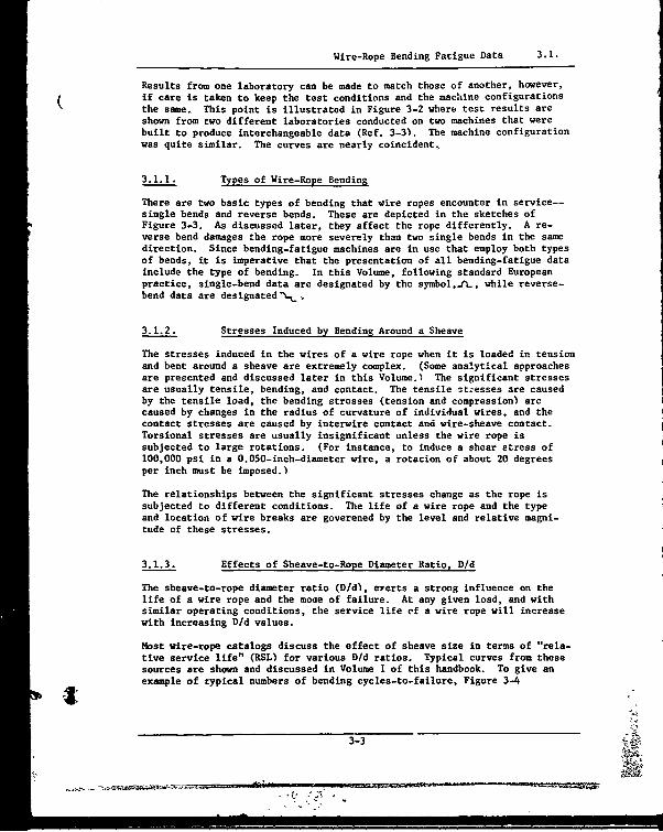
Results from one laboratory can be made to match those of another, however,if care is taken to keep the test conditions and the machine configurationsthe same, This point is illustrated in Figure 3-2 where test results areshown from two different laboratories conducted on two machines that werebuilt to produce interchangeable data (Ref. 3-3). The machine configurationwas quite similar. The curves are nearly coincident,
3.1.1. Types of Wire-Rope Bending
There are two basic types of bending that wire ropes encounter in service--single bends and reverse bends. These are depicted in the sketches ofFigure 3-3. As discussed later, they affect the rope differently. A re-verse bend damages the rope more severely than two single bends in the samedirection. Since bending-fatigue machines are in use that employ both typesof bends, it is imperative that the presentation of all bending-fatigue datainclude the type of bending. In this Volume, following standard Europeanpractice, single-bend data are designated by the symbol,f.ft, while reverse-bend data are designated•-•,
3.1.2. Stresses Induced by Bending Around a Sheave
The stresses induced in the wires of a wire rope when it is loaded in tensionand bent around a sheave are extremely complex. (Some analytical approachesare presented and discussed later in this Volume.) The significant stressesare usually tensile, bending, and contact. The tensile ittesses are causedby the tensile load, the bending stresses (tension and compression) arecaused by changes in the radius of curvature of individual wires, and thecontact stresses are caused by interwire contact and wire-sheave contact.Torsional stresses are usually insignificant unless the wire rope issubjected to large rotations. (For instance, to induce a shear stress of100,000 psi in a 0.050-inch-diameter wire, a rotation of about 20 degreesper inch must be imposed.)
The relationships between the significant stresses change as the rope issubjected to different conditions. The life of a wire rope and the typeand location of wire breaks are goverened by the level and relative magni-tude cf these stresses.
3.1.3. Effects of Sheave-to-Rope Diameter Ratio, D/d
The sheave-to-rope diameter ratio (D/d), everts a strong influence on thelife of a wire rope and the mode of failure. At any given load, and withsimilar operating conditions, the service life of a wire rope will increasewith increasing D/d values.
Most wire-rope catalogs discuss the effect of sheave size in terms of "rela-tive service life" (RSL) for various D/d ratios. Typical curves from thesesources are shown and discussed in Volume I of this handbook. To give anexample of typical numbers of bending cycles-to-failure, Figure 3-4
3-3

Effects of Sheave-to-Rope Diameter Ratio, D/d 3.1.3.
+
Single Bend JL
Reverse Bend
Figure 3-3. Types of Wire Rope Bending
50
Rope data-6 x 37 Warrington Seole, 1/2 and 3/4-inch diameter,regular - lay, IWRC, round-strand bright improved plow
40 50% 34% 17% )6 x 19 Warrington Seale, 1/2 and 3/4- inch diameter, ABS ABS ABSregular-lay. IWRC, round-strand bright improved I I
plow steel
300
SNote. Points represent on overage of all datagenerated at each condition for bothrope constructions
20 ABS= Actual Breaking Strength
20 -
Ii , 102 l .i . Ic I&Bending Cycles to Failure
Figure 3-4. Effect of D/d Ratio on the Bending-Fatigue Life
of IWRC Wire Rope at Three Load Levels
3-4
._________ ______ ___ B . •.,!
[ i l I I ll•[•T=='~ L -. ,= = .•- ,..
Effects of Sheave-to-Rope Diameter Ratio, D/d 3.1.3.
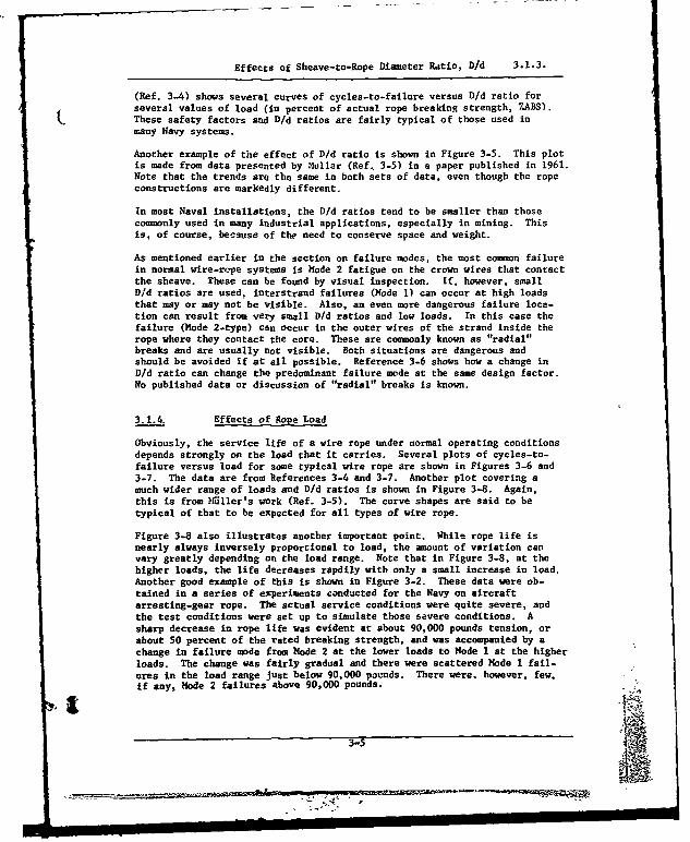
(Ref. 3-4) shows several curves of cycles-to-failure versus D/d ratio forseveral values of load (in percent of actual rope breaking strength, TABS).
( These safety factors and D/d ratios are fairly typical of those used inmany Navy systems.
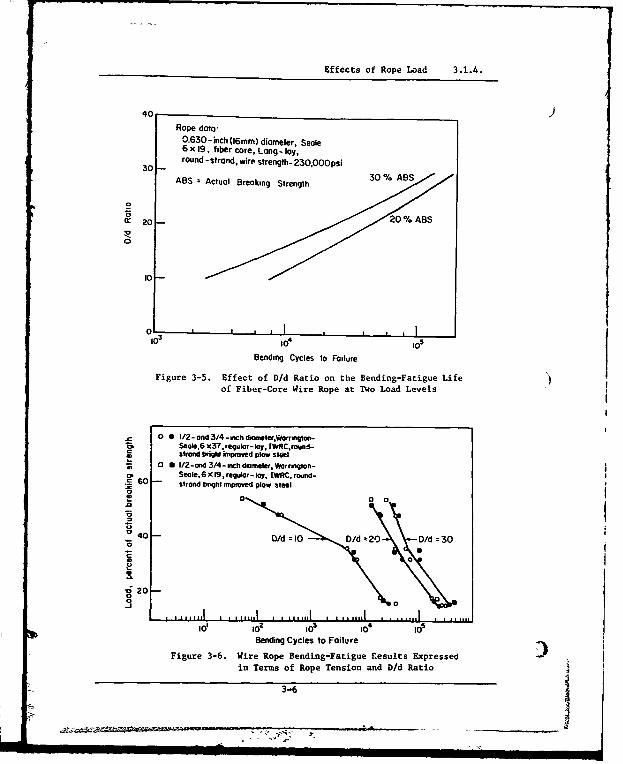
Another example of the effect of D/d ratio is shown in Figure 3-5. This plotis made from data presented by Muller (Ref, 3-5) in a paper published in 1961.Note that the trends are the same in both sets of data, even though the ropeconstructions are markedly different.
In most Naval installations, the D/d ratios tend to be smaller than thosecommonly used in many industrial applications, especially in mining. Thisis, of course, because of the need to conserve space and weight.
As mentioned earlier in the section on failure modes, the most common failurein normal wire-rope systems is Mode 2 fatigue on the crown wires that contactthe sheave. These can be found by visual inspection. If, however, smallD/d ratios are used, interstrand failures (Mode 1) can occur at high loadsthat may or may not be visible. Also, an even more dangerous failure loca-tion can result from very small D/d ratios and low loads. In this case thefailure (Mode 2-type) can occur in the outer wires of the strand inside therope where they contact the core. These are commonly known as "radial"breaks and are usually not visible. Both situations are dangerous andshould be avoided if at all possible. Reference 3-6 shows how a change inD/d ratio can change the predominant failure mode at the same design factor.No published data or discussion of "radial" breaks is known.
3.1.4. Effects of Rope Load
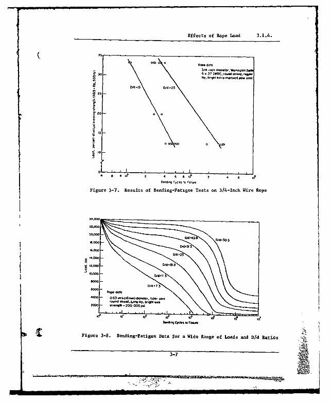
Obviously, the service life of a wire rope under normal operating conditionsdepends strongly on the load that it carries. Several plots of cycles-to-failure versus load for some typical wire rope are shown in Figures 3-6 and3-7. The data are from References 3-4 and 3-7. Another plot covering amuch wider range of loads and D/d ratios is shown in Figure 3-8. Again,this is from Mudller's work (Ref. 3-5). The curve shapes are said to betypical of that to be expected for all types of wire rope.
Figure 3-8 also illustrates another important point. While rope life isnearly always inversely proportional to load, the amount of variation canvary greatly depending on the load range. Note that in Figure 3-8, at thehigher loads, the life decreases rapdily with only a small increase in load.Another good example of this is shown in Figure 3-2. These data were ob-tained in a series of experiments conducted for the Navy on aircraftarresting-gear rope. The actual service conditions were quite severe, andthe test conditions were set up to simulate those savere conditions. Asharp decrease in rope life was evident at about 90,000 pounds tension, orabout 50 percent of the rated breaking strength, and was accompanied by achange in failure mode from Mode 2 at the lower loads to Mode 1 at the higherloads. The change was fairly gradual and there were scattered Mode I fail-ures in the load range just below 90,000 pounds. There were. however, few,if any, Mode 2 failures above 90,000 pounds.
3-5
Effects of Rope Load 3.1.4.
40Rope data-
0.630-inch (16mm) diameter, Seale6 x 19, fiber core, Long- lay,
30 round -strand, wire strength- 230,O00psi
ABS = Actual Breaking Strength 30% ABS
S20
'0
10-
Bending Cycles to Failure
Figure 3-5. Effect of D/d Ratio on the Bending-Fatigue Lifeof Fiber-Core Wire Rope at TWo Load Levels
0 0 1/2- ond 3/4-inch drnlerWarrringSeole,6 X37, regulor-lay, |IWRCround-strond bright improved plow steel
a 8 I/2-ond 3/4
-inch dearneter,Warrington-60 Seale, 6 x 19, regulor- lay, IWRC, round-
strand bright mnproved plow steel
0~ 00
o 0
"040 D/d 10 Dd z20 D/d 30
20
0 0
Bending Cycles to Failure
Figure 3-6. Wire Rope Bending-Fatigue Results Expressed •in Terms of Rope Tension and D/d Ratio
3-6
Effects of Rope Load 3.1.4.
35
05Y. br-,et e-l..u t 0p O m see
T /4.16 0/d 25
0 25-
1 20 a0
0 0
8"11-9 Cyoos '0 10/OO
Figure 3-7. Results of Bending-Fatigue Tests on 3/4-Inch Wire Rope
mlm
Correlation of Load and D/d Ratio With Rope Life 3.1.5.
3.1.5 Correlation of Load and D/d Ratio With Rope Life .
Several investigators have attempted to correlate the effect of combinationsof load, D/d ratio, and other parameters, such as rope construction, withrope life as measured in laboratory fatigue tests. (Calderale (Ref. 3-8)describes several methods along with his own analysis.) No universallyaccurate technique has yet been found that can be applied to all results.One problem mentioned earlier, that makes correlation difficult, is theeffect of different fatigue-machine configurations and operating conditions.Another is the lack of a commonly agreed-upon definition of rope failure.Many investigators use the complete parting of at least one strand as thefailure point, but others use a different criterion, sometimes unspecified.
Nevertheless, such correlations can be useful, especially in the absence ofany other rational method for predicting rope life. The one discussed here,the Drucker-Tachau factor (Ref. 3-9), has been found reasonably accurate fornormal loads and D/d ratios, so long as other factors--such as groove shape,sheave material, etc.--are constant,
This factor, hereafter called "B", is a dimensionless ratio derived from thenominal bearing pressure between a rope and a sheave and the ultimatestrength of the wire materials. It is defined as:
21B ý U-M (3-1)
where T - rope load, pounds
U - wire strengths, psi -
d - wire diameter, inches
D = sheave diameter, inches.
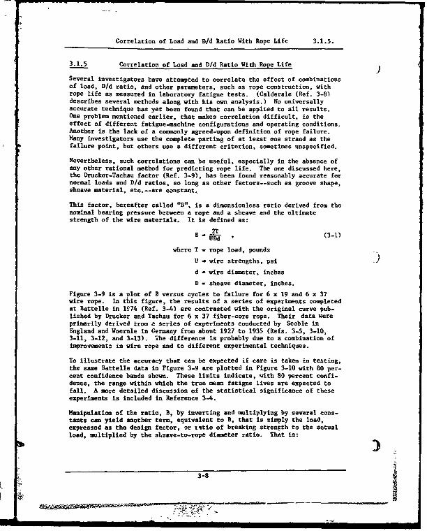
Figure 3-9 is a plot of B versus cycles to failure for 6 x 19 and 6 x 37wire rope. In this figure, the results of a series of experiments completedat Battelle in 1974 (Ref. 3-4) are contrasted with the original curve pub-lished by Drucker and Tachau for 6 x 37 fiber-core rope. Their data wereprimarily derived trom , series of experiments conducted by Scoble inEngland and Woernle in Germany from about 1927 to 1935 (Refs. 3-5, 3-10,3-11, 3-12, and 3-13). The difference is probably due to a combination ofimprovementz in wire rope and to different experimental techniques.
To illustrate the accuracy that can be expected if care is taken in testing,the same Battelle data in Figure 3-9 are plotted in Figure 3-10 with 80 per-cent confidence bands shown. These limits indicate, with 80 percent confi-dence, the range within which the true mean fatigue lives are expected tofall. A more detailed discussion of the statistical significance of theseexperiments is included in Reference 3-4.
Manipulation of the ratio, B, by inverting and multiplying by several cons-tants can yield another term, equivalent to B, that is simply the load,expressed as the design factor, or z'tio of breaking strength to the actualload, multiplied by the sl.eave-to-rope diameter ratio. That is:
3-8
_ _ _ __ _ _ __ _ _

Effects of Rope Load 3.1.4.
00
OiiCC
004-
S002 6 6VAd
IV6R C o oe mw 0 u fo 00u 00 fro m b r toy
0 MOroed plow el6x26.16xj9Cbss)Ww5oq05Se.reg"r lok, IWRC rope n,1foctwued from
00- b''ht Oftsteel6
1.949001 0 64x37 woe rope
SDruckerToCho
0 ,o , eo e'Berdaq Cycles to F~oture
Figure 3-9. Comparison of Bending-Fatigue Data
on the Basis of Bearing Pressure Ratio
oozeI l11 lili I I I I t illI I I I I I
Rope date6 x 36 W01r.oto 0 , e9.' loy.
003 - IWRC rol0e i0y010 fo br416
Wocr0ed pow steeli 8) 6 x 26.(6x8J Cfs) Wrrgwlcn Seot19) r-09" 1oy, IWR rope el foctuhed f0..
005 06910 I9 -. Plow steel
W • 4 Deeooes 80% elo,•ce 0000Nel-w s ( ) ore useter of selves
at 002 (a)
001-
18)
IDD I -l II I III
Cycles so Fore
SFigure 3-10. Eighty Percent Confidence Bands for
Selected Bending Fatigue Data
3-9
0,<0
Correlation of Load and D/d Ratio With Rope Life 3.1.5.
y - (df)(D/d) , (3-2)
where y - life factor
(df) = design factor (actualbreaking strengt
t,'load)
D = sheave diameter
d - rope diameter.
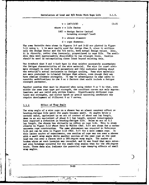
The same Battelle data shown in Figures 3-9 and 3-10 are plotted in Figure3-11 using Y. y is more easily used for design than B, since it utilizesonly the design factor and the D/d ratio, both normal design values. Also,it is directly, rather than inversely, proportional to rope life. The avail-able data were approximately describable by two straight lines, Cautionshould be used in extrapolating these lines beyond existing data.
One drawback that B and y both have is that neither accurately accommodatethe fatigue characteristics of the wire material, The wire (or rope) ulti-mate strength is used in both parameters and this indicates nothing aboutthe material's actual resistance to fatigue cycling. Some wire materialsare more resistant to triaxial fatigue than others, even though they mayhave similar ultimate strengths. It may be advantageous in some cases toconsider modifications to the B or y factors that would include a fatiguestrength parameter.
Another caution that must be observed when using either B or Y is that, evenwithin the same rope type and strength, the resultant curves are only approx-imations and are valid only within limits. Significantly different ropetypes and strengths, and either harsh or gentle operating conditions mayrequire development of different B or Y curves.
3.1.6 Effect of Wrap Angle
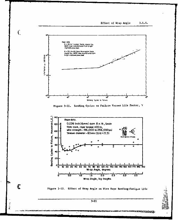
The wrap angle of a wire rope on a sheave has an almost constant effect onbending-fatigue life until the angle becomes small. At angles below acertain value, equivalent to an arc of contact of about one lay length,down to an arc equivalent of about 0.1 lay length, several investigatorshave reported a reduction in bending-fatigue life. Below an arc of 0.1lay length, the sheave has virtually no effect on rope life. This is shownclearly in Figure 3-12 where data by lEiller (Ref. 3-5) are shown for a ratheruncommon rope construction. The same phenomenon was reported in Reference3-14 and can be seen in Figure 3-13 (Ref. 3-7) for a more common rope. Inthis latter series of experiments, one section of rope was run over a sheavewith a small wrap angle while another section of the same rope at the sameload was run over a sheave with a 180-degree wrap angle. The number ofbroken wires at each location was recorded, and it was found that more exter-nal wire breakage occurred for the small wrap angles than for the 180-degreebends. These data also indicate the potential rope dama4ing effects of smallwrap angles.
3-10
Effect of Wrap Angle 3.1.6.
Rope data6 x 36 " '-- qto Secie. regmkl iOy.IWRC rope ,-ufoctwed froM brqhtrmpesoed plow site%
6 26, (6 x'9 Cilos$ WO)- aoto Secle.reg", lay. IWRC rope rr-toctured 6-00
g a br rt reprooed p0o- stM
e 01 .0 ido o' a
Figure 3-11. Bending Cycles to Failure Versus Life Factor, Y
140 Rope data.
120 0.236 inch (6amm) diam 8 x 19, Sealefiber core, rope tension 1100 Ib,wire strength - 196,000 to 256,000 psi R
100 - Sheave diameter - 80 mm( D/d = 13.3) a
80 RNO 53 d- 3 5-
0
0 060 0 00 @0
0 0 .0 0 0 0 000
0
0
eE 20
0L 20 30 40 50 60 70 OD 90 00 M1 12o0 10 14o 0 iO160 170 too ISoWrap Angle, degrees
I II I I I I
0 0.5 LO0 1.5 2.0 2.5 3.0 3.5Wrap Angle, lay ltngths
Figure 3-12. Effect of Wrap Angle on Wire Rope Bending-Fatigue Life
3-11
-- , , i - ii I ii II I I I III "+ IIII II IL
Effect of Wrap Angle 3.1.6.
20'
. o--
B~ Rope defo
A 3/4-mchdafeter. 6 37, vof.0cores,. reg3 r-Iloy.W•0 rrgton Seole. brgh ° exfro
.miored plea steel
S• 05 -- /Od reio =15
.o
o La
0 05 10 ' 1
Rope LOays O Steom wth S•ol I Wop Angle
Figure 3-13. Relative Wire Breakage as aFunction of Wrap Angle
3.1.7 Effect of Fleet Angle )
In normal wire-rope systems using recommended fleet angles (1/2 to 1-1/2degrees) and standard level-wind sheaves, the bending stresses induced bythe rope curvature perpendicular to the plane of the level-wind sheave areinsignificant. However, it is possible to induce significant bendingstresses under unusual conditions--large fleet angles and/or abnormal sheave-throat shapes. The rope must bend around the lip of the sheave throat asit approaches the sheave. If this bend is long enough and the effectivebending radius is small enough, this bend can affect rope life as much asinserting another sheave of that radius in the system.
If this condition is suspected, a layout should be made to check the effec-tive bending radius and arc of contact. Then, using the material presentedon the effects of wrap angle in section 3.1.6, and the material on theeffects of D/d in section 3.1.5, the severity of the rope usage conditionscan be assessed.
3.1.8 Effect of Rope Material
3.1.8.1 Wire Type.
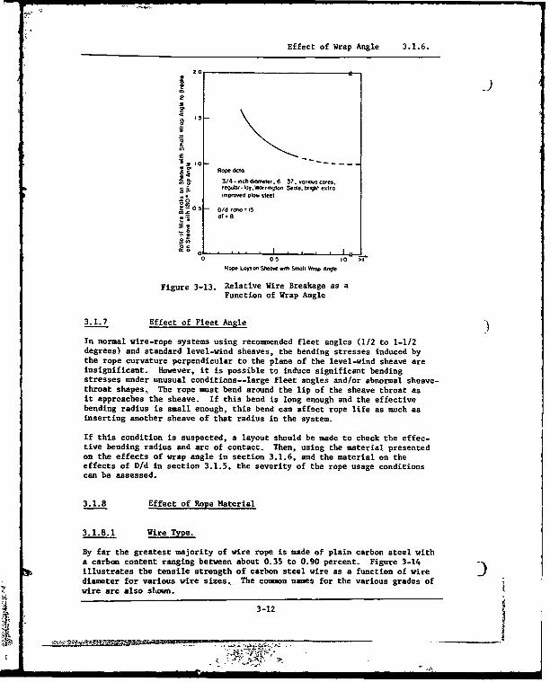
By far the greatest majority of wire rope is made of plain carbon steel witha carbon content ranging between about 0.35 to 0.90 percent. Figure 3-14illustrates the tensile strength of carbon steel wire as a function of wire Zdiameter for various wire sizes, The commn names for the various grades ofwire are also shown.
3-12

Effect of Rope Material 3.1.8.
00320
Fiue30-14. tr Tensile Step tsofCrbnSte
S240--
00- 005 OPO 0O5 0OW
Figure 3-14. Tensile Strengths of Carbon-Steel
Rope Wire as a Function of Diameterand Wire Grade.
Some wire rope is made of other metals, such as stainless steel and bronze.These are used in special situations, such as where corrosion, magnetic con-siderations, or high temperatures are involved. Some attempts have beenmade to use titanium wire with mixed success. Generally, wire ropes, madefrom other metals, when compareo to carbon steel ropes, are weaker and/orhave a lower fatigue life.
3.1.8.2. Wire Strength.
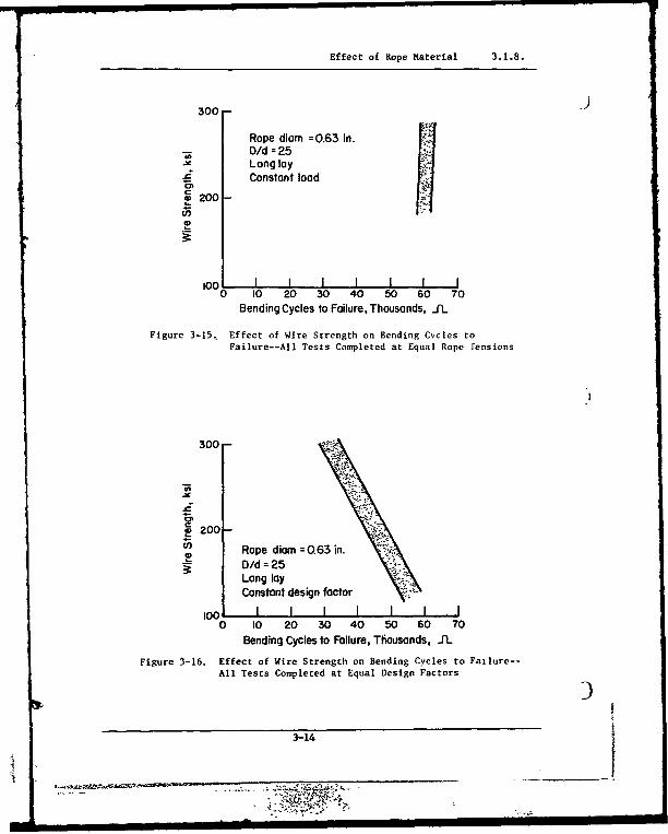
The effect of variations in carbon steel wire strength is shown in Figures3-15 and 3-16. These figures show trends of data presented in a German wirerope publication (Ref. 3-15). According to Figure 3-15, strength of wireswithin a wire rope may be varied over a substantial range (at least from200,000 to 300,000 psi), with all other factors such as load and D/d beingheld constant, and the bending-fatigue life will not change appreciably. Onthe other hand, if the design factor is held constant, as in Figure 3-16,the bending-fatigue life will decrease as the wire strength and rope loadare increased. Work by other investigators on American-made rope has con-firmed this trend, at least qualitatively, for higher wire strengths(Refs. 3-4 and 3-7).
3-13
......................... o
Effect of Rope Material 3.1.8.
300-
Rope diam =0.63 in.
SO/d = 25Lang layConstant load
a'
0 200
0 10 20 30 40 50 60 70Bending Cycles to Failure, Thousands, _IL
Figure 3-15, Effect of Wire Strength on Bending Cycles toFailure--All Tests Completed at Equal Rope Fensions
300-
S200-
U Rope diam =Q63 in.D/dd=25Lang layConstant design factor
1oo I0 10 20 30 40 50 60 70
Bending Cycles to Failure, Thousands, J1L
Figure 3-16. Effect of Wire Strength on Bending Cycles to Failure--
All Tests Completed at Equal Design Factors
3-14
4 _ _ _ __III I II I I I _ II I I

Effects of Swivels 3.1 9
( 3.1.9. Effects of Swivels
No definitive data are known on the effecrs of swivels on the bending endu-rauce of wire rope Some rather inconhlusi - data (Ref. 3-7) indicatethat swivels tend to degrade rope life. and their use should be avoided"when possible. Each case, however, must be individually evaluated. Theeffect of swivels on the static strength of various rope constructions isdiscussed later in this Volume under section 3 3. on Rotation and Torquc
3.1.10. Effects of Rope Construction
There are many wire-rope constructions available Most of these are specialand are particularly useful in special applications. In this section each ofthe various desizn factors in wire-rope cou-truction are discussed withrespect to their effect on bendine-faticue life in practice, all these far-tors must be considered jointly in the choice of a construction for a parti-cular purpose.
The data that are presented cannot be used quantitatively for field applica-tions. They all were obtained under laboratory conditions and are strictl3applicable only to the specific ropes and conditions that were tested. Theydo. however, clearly illustrate the trend' that can be expected in fielduse and, to a lesser degree, the amount of effect that changes in rope con-struction will i,7c on the endurance of wire rope in bending.
3 1 10.1. Lav
Three different lays of wire rope are availabl.--ordirary, Lang, and alter-nate. The first two are by far the most prevalent Alternate-lay ropes arenot common and, though no published data are available, are generally con-sidered inferior to ordinary- and Lang-lay ropes in bending endurance.
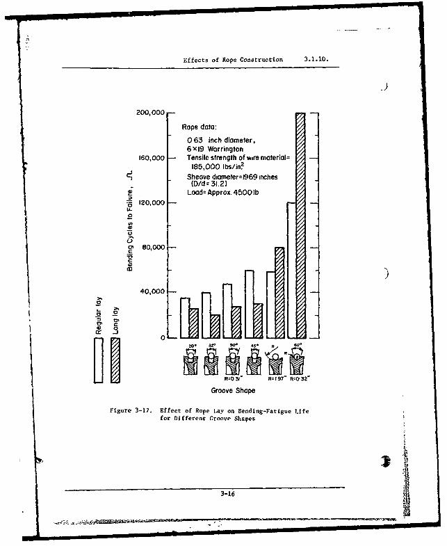
Under "nnr-al" conditions--round sheave grooves properly sized, ends re-straired from rotation, no reverse bending, reasonable D/d ratio, etc.--Lane-lav rope is superior to ordinary lay in bending fatigue life. Thissuperiority does not hold for conditions that vary from "normal". Figure3-17 (Ref. 3-15) illustrates this observation for a variety of abnormalsheave geometries.
3 1.10.2. Number of Strands
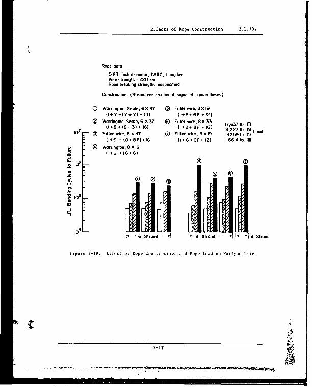
Figure 3-18 (Ref. 3-15) shows that soore constructions of eight-strand andnine-strand ropes are superior in bending fatieue to those with six strands.However, eight- and nine-strand ropes have a larger fiber core with corres-pondingly less metallic area and thus less strength for the same diameter.They are also less resistant to crushing.
;-A1
3-15
Effects of Rope Construction 3.1.10.
200,000
Rope data:
0 63 inch diameter,6X19 Worrington
160,000 Tensile strength of wire material=185,000 Ibs/in2.
Sheave diameter=1969 inches(D/d = 31.2)
Load: Approx. 4500 lb* 120,000U-
"04)
(31 80,000
3. 9
Groove Shp09 .
r 200 320.' 90 45 •
R=O03" Ro 197" R'O 32"
Groove Shape
Figure 3-17. Effect of Rope Lay on Bending-Fatigue Life
for Different Groove Shapes
3-16
A. ll:l ll l mmj
Effects of Rope Construction 3.1.10.
Rope do-a
0 63-inch diameter, IWRC, Long layWire strength - 220 ksiRope breaking strengths unspecified
Constructions (Strand construction designated in po;entheses)
(D Warrington Seale, 6 x 37 ® Filler wire,8x 19(1+7 +(7 + 7) + 14) (1+6+6F+12)
® Warrington Seale, 6 x 37 ® Filler wire, 8x33 17,637 b 0307 (+8+(8+3) + 16) (1+8+8F+16) 13,227 lb. E3 Load
10 (3 Filler wire, 6x37 63 Filler wire, 9xl9 42591b. 02(1+6 + (8+8F)+16 (1+6+6F+ 12) 6614 lb. U
( Warrington, 8 X 19_0(1+6 +(6+6)
CD 6CD6
o 10
6 strand 8 Strand 1 9 Strand
Figure 3-18. Effect of Rope Constr,'ciieoo a,•d Pope L~oad tin Fatigue Lizfe
3-17 '

Effects of Rope Construction 3.1.10.
3.1.10.3 Arrangement and Size of Wires. 9Ropes with single-operation strands, such as Seale, Warrington-Seale, andfiller-wire constructions, are generally superior to those with multiple-operation strands in bending endurance. Figure 3-19 (Ref. 3-16) illustratesthis effect and also shows that, under those specific tezt conditions, theropes with smaller wires--6 x 37--were superior to those with larger %,ires--6 x 19. This tendency is much less evident in other experiments conductedunder different conditions and on different ropes (Ref. 3-4). Figure 3-20shows the interaction of wire size (6 x 19 and 6 x 37) with load, whileFigure 3-21 shows it with D/d ratio. Note that under these conditions andwith this rope, the differences are much smaller, though the trend is stillthe same--the 6 x 37 rope has an equal or greater latigue life.
3.1.10.4 Preforming.
Preformed wire ropes have significantly better bending endurance than dononpreformed. Figure 3-22 (Ref. 3-17) shows this effect. Similar trendshave been reported in Reference 3-18.
3.1.10.5 Core.
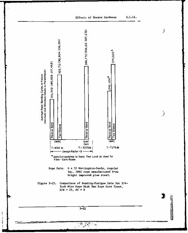
Wire ropes with a fiber core--either natural cr synthetic--appear to havea somewhat greater endurance in bending than those with an IWRC when operatedat the same design factor. Under this condition, for the same size rope, theload on the IWRC rope would be somewhat greater because of its inherentlyhigher strength. If, however, the two types of rope are operated at the sameload, their bending endurance is about the same, except under moderate condi-tions, where the fiber-core rope retains its suoeriority as Figures 3-23,3-24, and 3-25 (Ref. 3-7) illustrate. Data from this same reference on diff-erences between the various types of fiber cores-sisal, polypropylene, nylon,and Dacron--show mixed results and are not conclusive.
3.1.10.6 Special Constructions.
Innumerable special constructions of wire rope are made for particular appli-cations. These constructions are generally inferior in bending endurance tonormal round-strand wire rope. These constructions, however, may providenecessary increases in abrasion resistance, impact resistance or other fac-tors in situations where rope usage is especially severe or unusual.
Information presented in Volume I of this Handbook on the characteristicsof various rope constructions will be helpful in making a decision regarding
use of special construction ropes. For example, comparisons are made betweennonrotating, spin-resistant and torque balanced rope constructions (used forapolications requiring special rope rotational characteristicz); and smoothcoil, half-locked and locked-coil track strand ropes (used for tramway and
conveyer system applications). -
3-18
A9!

Effects of Rope Construction 3.1.10.
2005/8in diaom ropes with 2000 lb
175 - constant tension
150 Oldz 19 2 6 x 25 Filter
125 -
7���x x•9 Seal
'00 6 x19 Toro as"
o 25kgSo Ii I
S50 .00 150 200Number of Breaks m48in Test Length
:s20
YE 200 6 x 37 Filler"of 6 1 6 x 37 WeRoe
150- X 70"ve
:25-
0l 0. -aiu de6g fatr x / 3/7 T nche dmeer rp
7550
0 50 10 150 200
Number of Breaks 37 48 in Test Leay th
Figure 3-19. Cobrmparove Reverse-Bend Fatigue Resistanceof 6 x 19 and 6 x 37 Wire Rope
Test data
7 Did = 30, various design factors, 1/2 and 3/4- inch diameter rope
S6 x 37 Type, Warrington Seale, regular lay,IWRC. bright improved plow steel
6i --- 6 x 19 Type, Warrington Seale, regular lay,
I IWRC. bright improved plow steel
S5
C4
03
C -
2x,04
10S 4 x 10⁵
Bending Cycles to Failure, JL
C Figure 3-20. Effect of Design Factor on Bending-Fatigue Life
3-19 -g- ,l,
" """ .:.• ,•t 2: .•"

Effects of Sheave Hardness 3.1.11.
Test dotadf - 2 5. eh Ppoin t eprtett the oeoge of 8 secoens,
0 foro 1/2 and fo" 3/4 -ncth dw"nerteo 6 37 Type. worrn9ton Seole. regAOnJaoy. IWRC
Otr.igt relp'0oed plow st~ee
* 6 x 19 Type. Wocrngton Seole, -galor - loy. IWRC. bOletmpoved Plow steel
20
2604.9 CCles to F.-kve. An,
Figure 3-21. Effect of D/d Ratio on Bending-Fatigue Life
'2.000
Rope doft P'etfoc~ed
3/4o dnoestel. 6 x 37
e00s r810t -PltrOwd p:o steel"
8 PlO.- Oefornedd
oss:
40000
w *w-.0 0.0
Figure 3-22. Bending-Fatigue-Life Data for Preformed and NonpreformedWire Rope Under Various Tensile Loads
3-20
U~ I[ l InllIlli i lIli i liii iin i

Effects of Sheave Hardness 3.1.11.
Notes I a Otoa extropoloted to some test toad as used for ftber-core ropes2 Rope dota 6x37 Worrington-Seole, req"lor lay, IWRC rope naowfoclured
from bright, unproved plow steel
~ 0*
04*
*C- ,
Figure 3-23. Comparison of Bending-Fatigue Data for 3/4-1nch
Wire Rope With Several Core Types, D/d =25, df =3.
22."o- q6_ T- 960
Devq_ 0ato
Figure 3-24. Comparison of Bending-Fatigue Data for 3/4-Inch
SWire RoeWith Several Core TyeD/d =15, df =8.
-Rop oep
3-21 AM
011
Effects of Sheave Hardness 3.1.11.
a,-
NN
* in
ED
- 0to N 0
i to In
ror
In)
F- b -Cor Rpe
C,
brgw mroe po sel
0
E. - o
S--E
Co
c0 0
0r C
0 -
IWRC Sisal I WRCCore
!T=8312 lb T 72751bt T- 7275IlbDesign Factor =8-'
4,Data Extrapolated to Some Test Load as Used forFiber - Core Ropes
Rope Data: 6 x 37 Warrington-Seale, regularlay. NWRC rope manufactured frombright improved p10w steel.
Figure 3-25. Comparison of Bending-Fatigue Data for 3/4-Inch Wire Rope With Two Rope Core Types,D/d 25, df = 8
3-22

Effects of Sheave Hardness 3.1.11.
3.1.11. Effect of Sheave Hardness
The use of different metals in sheaves--hardened steel, cast iron, aluminum,bronze--reportedly has little or no effect on rope bending endurance (Ref. 3-15). Figure 3-26 (Ref. 3-1q) also shows almost no sheave material effect inan experiment comparing aluminum and hardened steel sheaves under rathersevere test conditions. However, one investigator (Ref. 3-16) has reportedsomewhat shorter rope life on soft metal sheaves. He surmises that this maybe due to sheave throat deformation and subsequent roughness. These data arepresented in Figure 3-27.
10 -Rope dote
1- . -inch, 6 x 25 filler wire,o Long lOy, round -strand
U
Note Sheave aineier - 24 inchesD/d= 175
-- 0 Hrdened steel siseos 0-- -- 'Aluminum sheave
I , I I I I !0 20 40 60 O0 100 i20
Rope Tensin,T,, 10 pounds
Figure 3-26. Results of Bending-Fatigue Tests on Aluminum and-~ Hardened Steel Sheaves.
3-23
• . . .m i. i. l .• =m .. . . . .

Effects of Sheave Hardness 3.1.11.
- Tool steeleeIU_ a Cast ironn
S 13 Ductile iron 0Si0 3 x A lu m in u m a llo y 0 1
0 0 Aluminum bronze X
o a:
Rope data:1/2-inch diameter, 6 x 25 bfiller wire, Lang lay, fiber u,core round strand, improved 61plow steel
D/d = 182 = I I I I I00040008 0012 0.016 0.020 0.024 0.028
Bearing Pressure Ratio (B)
Figure 3-27. Effects of Sheave 'laterial on Bending-Fatigue Life
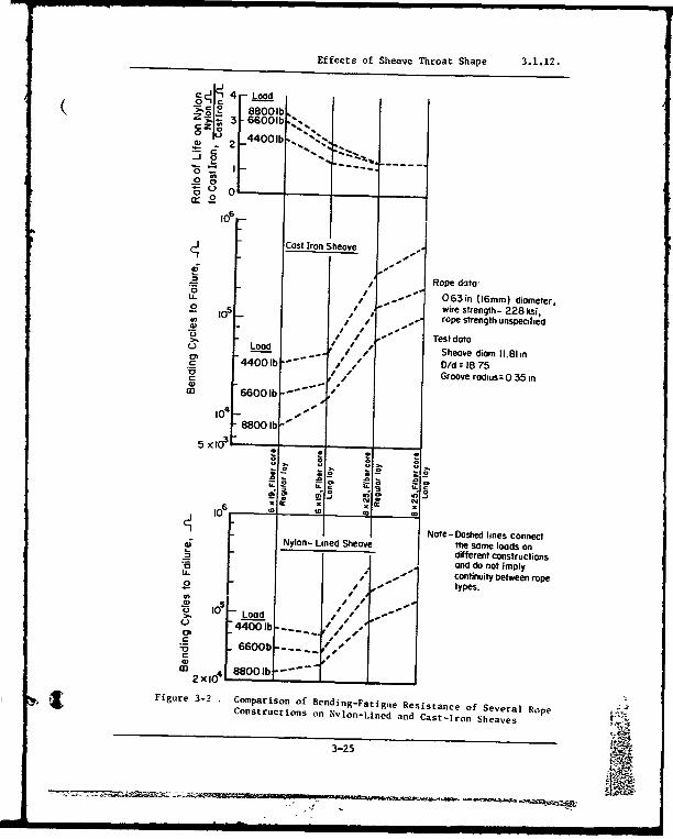
Softer sheave materials such as nylon have been shown to improve bendingendurance. Figure 3-28 (Ref. 3-5) compares the results of bending-fatigueexperiments using cast iron and nylon-P.,ed sheaves. It also illustratesthe previously discussed superiority in bending fatigue life of eight-strand construction over six-strand.
Wooden sheaves have been used in the past for some applications, but theireffect on rope life is minimal (Ref.. 3-21) and their resistance to abrasionis low.
3.1.12. Effects of Sheave Thrcat Shape
The effects of sheave throat shape can be seen in Figure 3-17 (which was pre-sented in an earlier section, 3.1.10 Effects of Rope Construction). Optimumbending endurance is obtained vith a round groove slightly larger than therope. Deviations from this configuration degrade rope performance ia bend-ing. As Figure 3-17 illustrates, the effect of throat shape variations onrope life is different for regular- and Lang-lay rope constructions.
3-24
S ..... . , =- = 1~at I Ir. l ilI =...
Effects of Sheave Throat Shape 3.1.12.
4 -J Load88001b
3 66001b..,
2 4401b.
.57
0
i6
Cost Iron Sheave - .
• / - Rope data-/ '- 063in (16mm) diameter,
0 lop- wire strength- 228 ksi,Si /! 0,•. rope strength unspecifjýed
S' - Test dataU Load Sheave diam 11.81 in4400.b Did = 18 75
/ Groove rodius= 0 35 in
ID 66001b -b
14 -, -
88001 b
s xtos.• *_ .- .2--o -- oa -ao -. ) •5
Note-Dashed lines connectNylon- Lined Sheave the Some loads ondifferent constructionsanid do not imply/ -- continuity between ropetypes.
U) 5' -0 Load - /
o 4 ob� .... . /.
S 660b 0b
2xa0 88001b
Figure 3-2 Comparison of Bending-Fatigue Resistance of Several RopeConstructions on Nylon-Lined and Cast-iron Sheaves
3-25
Effects of Corrosion, Lubrication, and Coatings 3.1.13.
3.1,13. Effects of Corrosion, Lubrication, and Coatings1
The effects of lubrication, coatings, and corrosion on the bending enduranceof wire rope are highly interrelated, Ropes are lubricated for two reasons:to retard corrosion, and to reduce interwire friction which promotes inter-wire motion as the rope is bent over a sheave. Metallic coatings such aszinc are applied primarily to reduce corrosion but also are said to act asa lubricant between the rope wires.
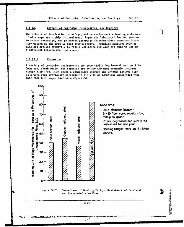
3.1.13.1. Corrosion
A variety of corrosive environments are potentially detrimental to rope life.Open air, fresh water and seawater are by far the most commonly incurred.Figure 3-29 (Ref. 3-5) shows a comparison between the bending fatigue lifeof a wire rope previously corroded in air with an identical uncorroded rope.Note that both ropes have been degreased.
100-
C go -
8 0 - Rope data-
0 / 0.63 diameter (16mm)
S70 - 6 x 19 fiber core, regular- lay,S0 • mild plow grade
60 - . Ropes degreased and weathered-0 unstressed for one year.
0L Bending fatigue tests on 15 75inch
U/ 0. -•
50 - sheave.
00 0
a.a
"U 330
20 20
CP
10 -1
igure 3-29. Comparison of Bending-Fati,,ae Resistance of CorrodedJand tlncorroded Wire Rope ) 4
3-26
Effects of Corrosion, Lubrication, and Coatings 3.1.13.
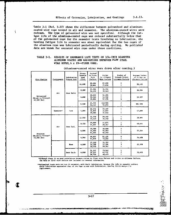
Table 3-1 (Ref. 3-22) shows the difference between galvanized and aluminum-coated wire rope tested in air and seawater. The aluminum-coated wires wereredrawn. The type of galvanized wire was not specified. Although the fat-igue life of the aluminum-coated rope was reduced substantially below thatof the galvanized rope for the seawater tests involving no lubrication, thebending fatigue life in seawater was about equivalent for the two ropes ifthe aluminum rope was lubricated periodically during cycling. No publisheddata are known for uncoated wire rope under these conditions.
TABLE 3-1. RESULTS OF ENDURANCE LIFE TESTS ON 3/4-INCH DIAMETERALUMINUM COATED AND GALVANIZED IMPROVED PLOW STEELWIRE ROPES, 6 x 19--FIBER CORE.
(Aluminum-coated wires were drawn after coating.)
Direet CtC1's'Tensile to Firt Cycles .wbtr of Averate Xorher
Luobrication Load .are !o I Itimste Strands Broken of Carles toWire Coatin Environmeet D.at Test '1b.) Failure Rol, i-a , .ltiate Failure h tir ie FilI-re
11.400 1is40O 27.200 2 26.12S.:9,61 25,0500 1
9.120 2126 3744 1 3054.10 34.120 39.3n3 I3,5
Aie Once Dail, L
d20.633 51.295 1(re-k =nStn 6.800 52.280 52.952 • 53.9074i .,00 lbs) 2t.4. 0 0 57.494 6
4550 lb.71S ___l'__1___90
31.77 4 110.9356.560 42.414 92.046 1 101 990
32.442 45 .07S.-W a ooe 6,800 33.859 ".4017 47.889
30.050 54.042 1
il.400 22.570 29.:!2 1 ,.2.510 23.240 6
9.120 29.000 41 75 40.61
31:825 39.14" 1Onr00e Sail -- '1
33 700 5S.0 26,800 25.930 1:',S.03 1 57.514
41.235 61.E .69
43".03 lb.) ,563 5 921 81,12.3 .(1r0ei8 721232 6 76.678
17:151 24.322 1lose 6.800 19.200 27.104 3 23,578
13,150 19,367
31.145 T 53.9,2 1Once D5.0, A.- 37.355 '2, 31 2 52.455
. .7 1 6 , 7 3 1 11
-Althos52h there is no good correlatl-o betwee, oycles to first wire failre and cyoles to Oltisate failure,the data oo first wire fatll re are 1uloded i•e erae i tforeatio.
oocan zled ropes n ere eot run it 1 rugat.e, ith dadl, lobetiatlen. because -he life in seawater ,ithoct
d=tty .. hbrictio approaches that of the rope im air with lubricats-, lea~tng little ssarl-n f-rsqtroneent.
3-27 -5.
Effects of Corrosion, Lubrication, and Coatings 3.1.13.
3.1.13.2. Lubrication
Current Navy specifications (RR-W-410C) require that uncoated steel wireropes be coated with a suitable lubricant during the process of manufacture.The lubricant must have a mineral base compounded with additives designedto provide corrosion protection and lubricating qualities during shipping,storage, handling, and the initial period of service and a suitable basefor subsequent field relubrication, The lubricant must also be free fromsubstances injurious to steel wires and fiber cores.
Proper lubrication of wire rope running on sheaves is an important factor inmaximizing '-tigue life. An example of the effect of lubrication is shownin Figure 3-30 (Ref. 3-15). As the figure shows, lubricated rope can havea lifetime as much as seven to eight times longer than unlubricated rope.The type and frequency of lubrication is known to influence wire-ropefatigue life, but few well-documented data are available.
3.1.13.3. Coatings
Three types of coatings are commonly available on wire rope--zinc, aluminum,and plastic. Of these, zinc is by far the most common,
Zinc-coated wire for ropes is manufactured according to three basic proce-dures:
I. Hot-dip galvanizing with no further processing (finally galvan-ized wire)
2. Hot-dip galvanizing at an intermediate stage in the drawingprocess (drawn galvanized wire)
3. Electrogalvanized wire,
It is generally agreed (Refs. 3-15 and 3-23) that in noncorrosive environ-ments finally galvanized rope is somewhat weaker and less resistant tobending fatigue than rope of the same type made from bright (uncoated)wire. However, the effect of reduced bending fatigue endurance is probablyless noticeable and may even be reversed in many corrosive atmospheres,especially seawater, Unfortunately, no published data are known to existthat verify these statements.
On the other hand, there is general agreement (Refs. 3-15, 3-16, and 3-23)that wire rope made from drawn-galvanized and electrogalvanized wire isequal in strength to uncoated wire rope and is superior in bending endurancein both corrosive and noncorrosive atmospheres. Figure 3-31 (Ref. 3-23)compares the bending fatigue behavior of drawn-galvanized wire rope withthat of uncoated wire rope. No details describing loads or sheave sizeswere given for these tests. The testing machine imposed reverse bends, andthe rope was rotated during testing.
The thickness of zinc coating also appears to have an effect on bendingfatigue life. Figure 3-32, which is also from Reference 3-23 and also pro-vides no test details, shows not only the superiority of drawn galvanized
3-28
! -,

Effects of Corrosion, Lubrication, and Coatings 3.1.13.
LLubricatedo0o
Unlubriooted , I I i
0
S Rope data NO fi t- C-.0 4,(1 m" ~.
$0t,,Nlh -23ý0.001o, Design Factor
15 75 5 375 3Design Factor
Figure 3-30. Effect of Lubrication on the Bending-Fatigue Lifeof a Rope for Various Design Factors.
100
90
80 -6 x 41, Seale-Warrington,bright
70
S60
0
5 -50"6 6 x 41, Seole - Wcrrington, drown golvanized
40 -Ez
30 -All other rope parameters similar
20-
I0 i
00 10,000 20,000 30,000 40,000 50,000 60,000
Reversed Bending Cycles,
Figure 3-31. Comparison of Bending Endurance at Wire Ropes Made FromBright (Uncoated) and Drawn Galvanized Wire.
3-29 --t*
iNY
Effects of Corrosion, Lubrication, and Coatings 3.1.13.
and electrogalvanized wire rope, but also indicates a substantial increasein fatigue resistance for rope made from wire with thicker zinc coatings,No American data are known on this subject.
Aluminum-coated wire for wire rope has been used infrequently. Few data areavailable for this type of rope, especially in bending fatigue. The datashown in Table 3-1 represent most of the available published information.
Plastic-coated wire rope is widely used in light service operations and inspecial applications such as food-handling equipment. Figure 3-33 (Ref. 3-24) shows comparative fatigue life data for bare and nylon-jacketed ropes.Although the sizes of the ropes are not given, they are believed to be quitesmall. Larger plastic-coated ropes are being used with increasing frequency.No published bending-fatigue data are known to be available for the largerplastic-coated sizes.
A major difference in the type of corrosion resistance provided by the met-allic coatings, as compared to the plastic, is the wire behavior after thecoating has been pierced. Both zinc and aluminum coatings protect the steelwire galvanically, and small holes do not adversely affect the corrosionprotection provided by the coating. However, once a plastic coating hasbeen penetrated, it no longer protects the steel and may even serve to retaincorrosive fluids within the cable.
3.1.14. Effect of Reversed Bends
Figures 3-34 and 3-35 (Ref. 3-5) show the adverse effect of reverse bendingfor Lang-lay and regular-lay ropes under various loads and sheave ratios.Note that Lang-lay ropes are more affected than regular-lay, Table 3-2(Ref. 3-7) also illustrates the fatigue life reduction due to reversed bends.
Table 3-2. FATIGUE LIFE REDUCTION DUETO REVERSE BENDS
Rope Data: 3/4-inch diameter, r';tular lay, IWRC,Rp 6 x 37, extra improved plow steel
SRope Life
Diameter, Design Reductioninch D/d Factor Factor*
1/2 15 3 0.8071/2 15 8 0.7401/2 25 3 0.5271/2 25 8 0.556
3/4 15 3 0.6973/4 15 5 0.8483/4 15 8 0.7933/4 25 3 0.6703/4 25 8 0.819
Average 0.717
Reverse-bend cyclesS*•ife reduction factor n Singlebed cyles
- -3-30
I L-=-_____ __
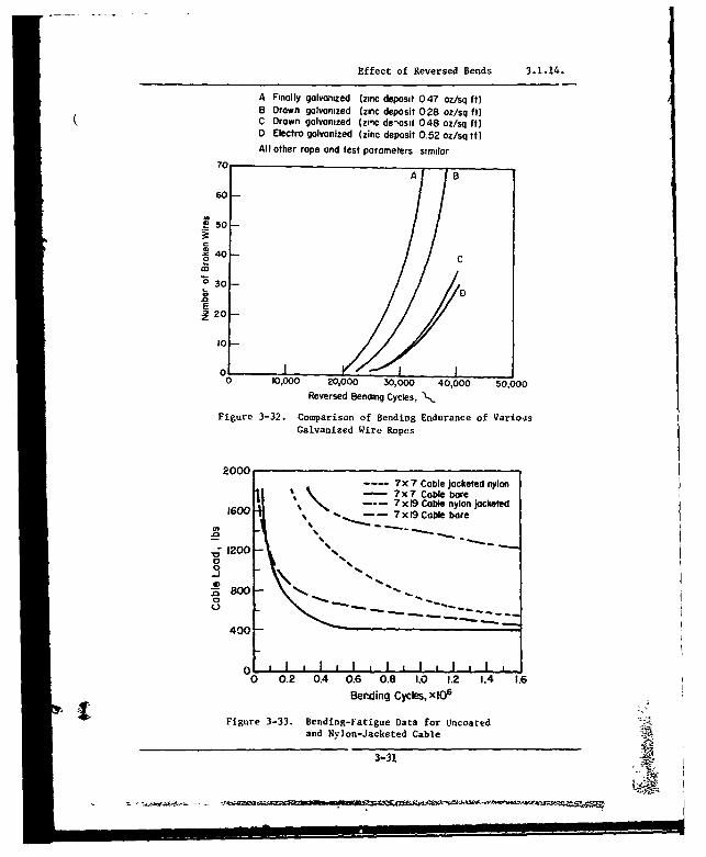
Effect of Reversed Bends 3.1.14.
A Finally galvanized (zinc deposit 047 oz/sq ft)B Drawn galvanized (zinc deposit 028 oz/sq ft)
( C Drawn galvanized (zinc de'osit 048 oz/sq ft)D Electro galvanized (zinc deposit 0.52 oz/sq tt)All other rope and test parameters similar
70A B
60
2 50
40
C"o 30
C 0oE
20
10
0 IO,O00 20,000 30,000 40,000 50,000Reversed Benaing Cycles, ',
Figure 3-32. Comparison of Bending Endurance of VariousGalvanized Wire Ropes
2000x-- 7x 7 Cable jacketed nylon\t • 7X7 Cable bare
600 I --- 7x 19 Cable nylon jacketed10 %- 7 x 19 Cable bare
.' 1200
0 II
800 -
400 •
0 0.2 0.4 0.6 0.8 1.0 1.2 1.4 1.6BerJ~ing Cycles, x lOr6
Figure 3-33. Bending-Fatigue Data for Uncoated aand Nylon-Jacketed Cable3o-3
II II I ! o
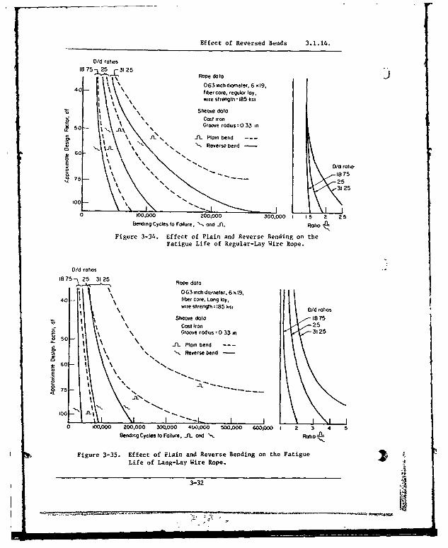
Effect of Reversed Bends 3.1.14.
D/d ratios
i875a25 f325
I '.Rope da ta40063 inch diameter. 6 xs1,
40- • fiber core, regular lay,wire strength t185 ksi
!6\ Sheave data
t5
N
s
. •Cost iron5oG fS Groove radius= 0 33 in
50'5o•. 0 \•J'.
Plain bend ----
fL. Plain bend'5 ''. •Reverse bend
60 %
o '
75
25
0 '5 0/dralao
N25
100 \
N N••-
0 100,000 200,000 300,000 I 15 2 2 5Bending Cycles to Failure, ", and JfL Ratio
Figure 3-34. Effect of Plain and Reverse Bending on theFatigue Life of Regular-Lay Wire Rope.
V/d ratios
18 75 -ý 25 3125Roedt18 4 ---•
Rope data
0 O63 inch diameter, 6 x19,
40-- fiber core. Long lay,wire strength - 185 ksi D/d rotos
Sheave data 1875Cost iron 25
Groove radius = 0 33 in 3125
-IL Plain bend ---
N -. Reverse bend
S75-
I00 --
"- "
_
10I 1-. ----
I I
0 0oo,000 200,000 300,000 4W0,000 500,000 60p.000 2 3 4 5
Bending Cycles to Failure, .IL ond Ratio A
Figure 3-35. Effect of Plain and Reverse Bending on the FatigueLife of Lang-Lay Wire Rope.
3-32
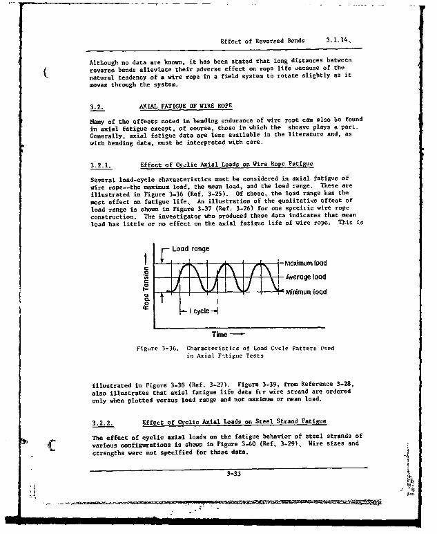
Effect of Reversed Bends 3.1.14,
Although no data are known, it has been stated that long distances between
reverse bends alleviate their adverse effect on rope life vecause of the
natural tendency of a wire rope in a field system to rotate slightly as it
moves through the system.
3.2. AXIAL FATIGUE OF WIRE ROPE
Hany of the effects noted in bending endurance of wire rope can also be found
in axial fatigue except, of course, those in which the sheave plays a part.
Generally, axial fatigue data are less available in the literature and, as
with bending data, must be interpreted with care.
3.2.1. Effect of Cyclic Axial Loads on Wire Rope Fatigue
Several load-cycle characteristics must be considered in axial fatig,e of
wire rope--the maximum load, the mean load, and the load range. These are
illustrated in Figure 3-36 (Ref. 3-25). Of these, the load range has the
most effect on fatigue life, An illustration of the qualitative effect of
load range is shown in Figure 3-37 (Ref. 3-26) for one specilic wire rope
construction. The investigator who produced these data indicates that mean
load has little or no effect on the axial fatigue life of wire rope. This is
Load range
Maximum load
Average load
Minimun load
PfI cycle--
Time
Figure 3-36. Characteristics of Load Cycle Pattern Usedin Axial F.tigue Tests
illustrated in Figure 3-38 (Ref. 3-27). Figure 3-39, from Reference 3-28,
also illustrates that axial fatigue life data fcr wire strand are ordered
only when plotted versus load range and not maximum or mean load.
3.2.2. Effect of Cyclic Axial Loads on Steel Strand Fatigue
The effect of cyclic axial loads on the fatigue behavior of steel strands of
various configurations is shown in Figure 3-40 (Ref. 3-29), Wire sizes and
strengths were not specified for these data.3
3-33 t,
< i Iq;

Effect of Cyclic Axial Loads on Steel Strand Fatigue 3.2.2.
111 1 I I I Ill lIT., V- !-L•
LONg LOY E.-. a Lw d
"" 04 0 0RL 0 --IWR A.,MrNA. -C Q
_ -0 0
3~T~Tutl fip-j 70 Hz
0 0-
- [ 1, I1 I I-I I f II 11111
0I I1111g00 - a
Cycles to Failure
Figure 3-37. Axial Fatigue Test Data for k-Inch Diameter,6 x 25 Polypropylene Core and IWRL.. BrightImproved Plow Steel, Wire Rope.
Load Range
40 % ABS 30 % ASS
30- 0U a 0 a a
"20- a a a 0 0
* Long IWRC Each point averogeSLOng Poly of two speciuens
* Regular IWRCcRegular Poly
ABS = Actual Breoking Strength
I~ , ,o , ,t'o I
Cycles to Failure
Figure 3-38. Effect of Mean Load on the Axial Fatigue of IWRC
and Polypropylene Core Wire Rope. 4-
3-34

-TEffect of Cyclic Axial Loads on Steel Strand Fatigue 3.2.2.
& 120
2 80 S 0
u60 * 0
,F 40 -0
aE 1O --E- c I I I ,l1hl I , I.ll
:E eo 2 4 G810 2 4 681o?Fatigue Life, cycles
a Maximum Load Versus Cycles to Failure
:E 120
60-~Ia
•,40 -
T;0
0 2040-J
0 I I [ I 'i'1 I i I l h
d 0042 4 681d 2 4 6810s
Fatigue Life, cycles
b Mean Load Versus Cycles to Failure
50
50
S40 -
.30 0
4,
.20-
c 10"0 I I ldhhl I .IiIsl
0 0 1
0 2 4 681( 2 468Bi'10Fatigue Life, cycles
c. Load Range Versus Cycles to Faikure -Z
Figure 3-39. Effect of 'laxicatm. Mean and Range of Load on theAxial Farigue Life of I-Inch, I x 19 (Galvanized Strand JI
3-35
-- N
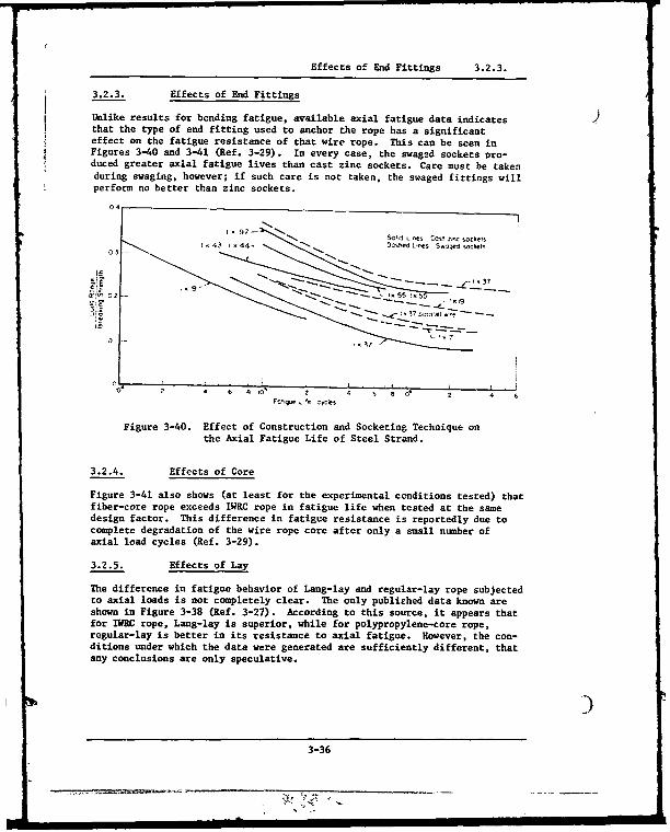
Effects of End Fittings 3.2.3.
3.2.3. Effects of End Fittings
Unlike results for bending fatigue, available axial fatigue data indicates )that the type of end fitting used to anchor the rope has a significanteffect on the fatigue resistance of that wire rope. This can be seen inFigures 3-40 and 3-41 (Ref. 3-29). In every case, the swaged sockets pro-duced greater axial fatigue lives than cast zinc sockets. Care must be takenduring swaging, however; if such care is not taken, the swaged fittings willperform no better than zinc sockets.
0.
l97- 'W• ~SoSI c,nes Cost one soceets
43 1 44, OwOedes L--Sged.ojwkets0 3 -. ..
21 0 -• toS ,523
-& .-~3 7oo~~eh..
ý9- -
02 -. 551X5
C'0 2 ~ 6 60~ ' 9' 2 4F 'e Ccyes
Figure 3-40. Effect of Construction and Socketing Technique onthe Axial Fatigue Life of Steel Strand.
3.2.4. Effects of Core
Figure 3-41 also shows (at least for the experimental conditions tested) thatfiber-core rope exceeds IWRC rope in fatigue life when tested at the samedesign factor. This difference in fatigue resistance is reportedly due tocomplete degradation of the wire rope core after only a small number ofaxial load cycles (Ref. 3-29).
3.2.5. Effects of Lay
The difference in fatigue behavior of Lang-lay and regular-lay rope subjectedto axial loads is not completely clear. The only published data known areshown in Figure 3-38 (Ref. 3-27). According to this source, it appears thatfor IWRC rope, Lang-lay is superior, while for polypropylene-core rope,regular-lay is better in its resistance to axial fatigue. However, the con-ditions under which the data were generated are sufficiently different, thatany conclusions are only speculative.
3-36
I I II II I III I I~ili IIII I l

Effects of Lay 3.2.5.
( or
04-
7A IWRC A& A
• -/8I x 7O~o ~-, ~ IWC A AWjRA A
02 A.
IWRC FWe
01_ 1/2I-0 6X 25 Long"~oA 7/8- In 6 X25L~nq My
a 2 -7/8-s 6 37 Regco.,ly
i I i i I~ ~ I ' iL , , • I
e 2 4 6 e 2 6 5 soFotqse Lfe yc"
Figure 3-41., Effect of Diameter, Core Material,Construction, and Socketing Techniqueon the Axial Fatigue Life of Steel WireRope
3.2.6. Effects of Rope Construction and Material
The results of a series of cyclic tension tests on different constructionsare shown in Table 3-3 (Ref. 3-30). These experiments were conducted in airwith the ends fixed to prevent rotation. Figure 3-42 (Ref, 3-29) showsthe effect of wire material on axial fatigue life of wire rope. At thehigher load ranges, rope behaves the same in axial fatigue as in bending--operating at the same design factor, the rope made from the stronger wirehas a shorter life. However, at the lower load ranges the difference almostdisappears and ropes made from different strength wires behave similarly.
3.2.7. Effect of Frequency
The effect of cyclic frequency on axial fatigue life is believed to be smallso long as reasonable rope temperatures are mzintained. There is, however,no trustworthy published eats to firmly substantiate this belief. Of course,if the frequency is high enough to raise the rope temperature to a point
5"where the rope material properties are affected, the fatigue life will be*changed.
3-37
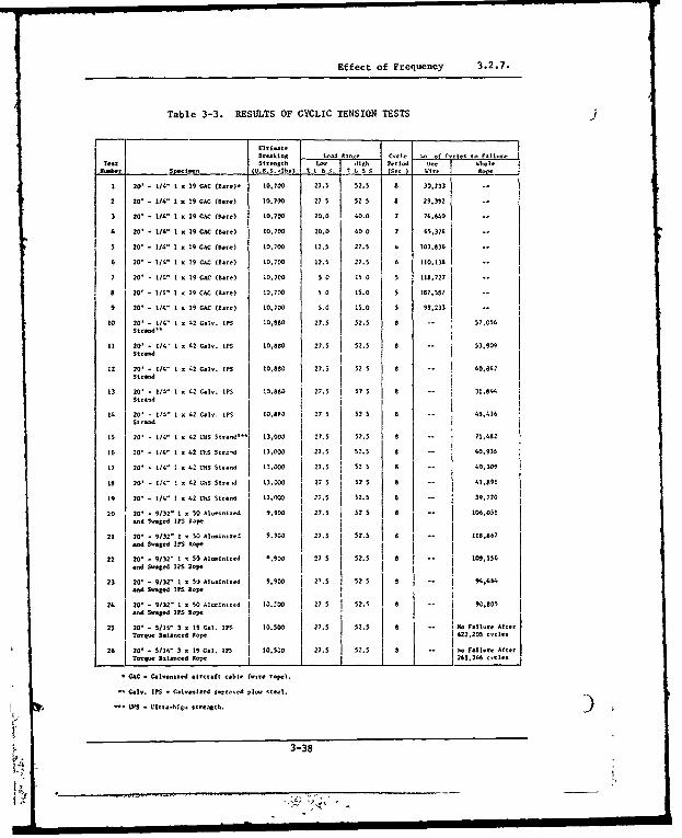
Effect of Frequency 3.2.7.
Table 3-3. RESULTS OF CYCLIC TENSION TESTS
i U""2 0* 1/.. 1 l :99 I27 5 a 9
I..br Seed.., j f0.3.s.-lbsO t 7 . 35 . (Or,) lieope
20' 1 /li" 1 x 19 CAC (lare)" 10.700 27.5 02.0 7 74.640
2 20' - 114 1 e 19 CAC (Bare) 10.700 27 5 52 0 29.392
3 20t - 1/4" 1 x19 CMC (Bare) 10.700 20.0 4.0.0 7 74.640 -
5 20' - 1/4" 1 e9 GAC (Bare) 10.70 20 40 0 6,7
6 20' - 114" 1 • 19 GAC (Bare) . 1,700 12.5 27.5 103,836
20' - 1/." 1 e 79 G flare) :10-700 12.5 21.1 110.1-
7 20' - 1/4" 1 19 GC flare)C 10.700 0 15 0 0 110.727
8 20' - 114" 1 , 1 C (CaC e) f 10.700 5 0 15.0 5 187,507
9 20' - 1/4 I. 19 CAC (lane) 10.700 5.0 15.0 5 99.233
10 20' - 114" 1 .o2 G.a. I11 10,880 27.5 52.5 8 -- 57,056Strand'
11 20' - 1/4' 1 , 42 Gal,. IS 10,800 27.5 52.5 8 -- 53.909
12 20- - 114" 1 .4
2 CGaý. IPS 10,.80 27.5 125 0 -- 40.042
13 20' 1/4" 1 . 42 Ga.n. 1- , 12.50 27.5 5 ? 8 -- 231.844
Strand n1 . 7 7
14 20- 1/4" I . 2 G4 a. IPS 10.830 I I4416.strand0.1
is 20' - 1/4" 1 , 42 '.11 Strand-ni 13.0093 27.5 52.5 . -- 11,48,
16 20 - 1W 1 x 42 LI4S Strad 13.502 27.5 52.5 -- 40.936
1 20' 1/4' 1 . 42 V.M5 S~rand 13.000 27.5 52 5 8 -- 40.309
S 20' - 1/4'" 1 42 xQIM S-ra J 13.000 27 5 52 5 8 - 41.891
19 20' - 1/4" 1 . 42 0.3 Sira•- 13 002 27.5 52.0 0 -- 39.770
20 20' .9/32" I 0.50 Alorinined 9:900 27.5 52 05 f5 -- 106,021a n d 5 9 ý te d M• ; o peI
21 70' - 9/32" 1 . 50 Alnaln-e1 9.900 27.5 52.5 f-..867
and Swaled 170 Rope
22 20' - 9/32" x 50 Alelnleed 0-900 27 5 52.5 85 -- 109,1561nd swage 5 lap vope
23 20' - 9/32- 1 x 50 Aln.inlzed 9.900 2'.5 52 .5-- ,44.ad swaged IPS .op-
24 20' - .9/3'2"I.nRAlAnln-aed 11,-02 27 5 52.5 8 -- 90.105
Torque Balanced laop. 622.200 cycles
26 20' - 5/16v 3. 19 Cal. 11 W 10..10 21.S 2.0 0 -- lo Failure Af.1 e
Torq u5e lalanoed Rop e _ _ J 261.266 n ycle s
0G.C CeI.|va.ted ae. cable (eir. rope).
Gal,. IP - ia-lnanbend lý.oo.ed plo- .tetl.
WS0 lliea-h1i. streeaulh.
3-38
m n mn m I m'n n ,0m n- I i l N l m l
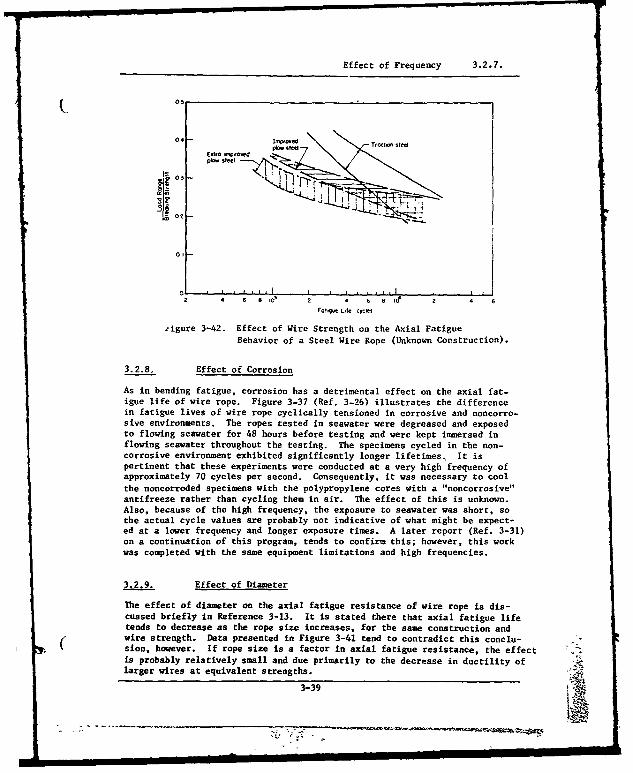
Effect of Frequency 3.2.7.
04
E.fta O 'p,0dpJow steel
03
Orr0 2
2 4 6 80 2 4 6 8 n6 2 4
Fol" LAfe ¢yaS
zigure 3-42. Effect of Wire Strength on the Axial FatigueBehavior of a Steel Wire Rope (Unknown Construction).
3.2.8. Effect of Corrosion
As in bending fatigue, corrosion has a detrimental effect on the axial fat-igue life of wire rope. Figure 3-37 (Ref. 3-26) illustrates the differencein fatigue lives of wire rope cyclically tensioned in corrosive and noncorro-sive environments. The ropes tested in seawater were degreased and exposedto flowing seawater for 48 hours before testing and were kept immersed inflowing seawater throughout the testing. The specimens cycled in the non-corrosive environment exhibited significantly longer lifetimes, It ispertinent that these experiments were conducted at a very high frequency ofapproximately 70 cycles per second. Consequently, it was necessary to coolthe noncorroded specimens with the polypropylene cores with a "noncorrosive"antifreeze rather than cycling them in air. The effect of this is unknown.Also, because of the high frequency, the exposure to seawater was short, sothe actual cycle values are probably not indicative of what might be expect-ed at a lower frequency and longer exposure times. A later report (Ref. 3-31)on a continuation of this program, tends to confirm this; however, this workwas completed with the same equipment limitations and high frequencies.
3.2.9. Effect of Diameter
The effect of diameter on the axial fatigue resistance of wire rope is dis-cussed briefly in Reference 3-13. It is stated there that axial fatigue lifetends to decrease as the rope size increases, for the same construction andwire strength. Data presented in Figure 3-41 tend to contradict this conclu-(" sion, however. If rope size is a factor in axial fatigue resistance, the effectis probably relatively small and due primarily to the decrease in ductility oflarger wires at equivalent strengths.
3-39
IIU n I n n n n n u l| I I I I I l I I I l l | I I I l II I I I 1

Effects of Lubrication and Coating 3.2.10.
3.2.10. Effects of Lubrication and Coating
Figure 3-43 (Ref. 3-29) shows that lubrication and coatings have an effecton the axial fatigue behavior of steel wire strand. No similar data areknown for wire rope, but the trends would quite likely be similar.
025 - A,
a!
05
Figure 3-43. Effect of Wire Coating and Lubrication on the AxialFatigue Life of 3/4-Inch, 1 x 37 Steel Wire Strand.
It has also been stated (Ref. 3-29) that zinc coating of rope wires (presum-ably drawn after coating ) may cause slight improvement in the axial fatigueerdurance of wire rope, but no data have been found in support of thisconclusion.
3.3. ROTATION AND TORQUE
A characteristic of wire rope that must be considered in all systems,especially those in which both ends are not fixed against rotation, is thetension-induced torque and resulting rotation. The construction of nearlyall wire ropes is such that a tension load induces torque in the rope.Certain three-strand constructions are very nearly torque-balanced, but insome other constructions the torque build-up is surprisingly high. Lang-layrope is particularly prone to rotation and should never be used with an endfree to rotate. This rotation can be very troublesome in several respects.
3.3.1. Kink Formation
If the load on a rotated rope is suddenly removed (or even decreased substan-tially) the rope may loop, and then, as the load is reapplied, form a tightkink which will drastically lower the rope breaking strength. This behaviorwas successfully simulated in a laboratory investigation (Ref. 3-32) conductedto determine the tension-rotation, torque and kink characteristics of severaltypes of low-torque oceanographic tension members, contrahelically wrappedstrands and two types of three-strand wire rope. Kinks were induced bysuspending a length of rope, applying a low tensile load with a free-hangingweight, and then rotating the rope manually. Applied torque was measured Jintermittently, until a kink formed. A brief summary of the results is shownin Table 3-4.
3-40

Kink Formation 3.3.1.
L 2°
oT
z
- . - - -..
c -
L20
-----------
U _________________3 __41
U)alz:
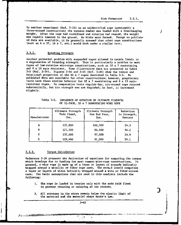
Kink Formation 3.3.1.
In another experiment (Ref. 3-33) on an unidentified rope (presumably athree-strand construction) the tension member was loaded with a free-hangingweight, After the rope had stabilized and rotation had ceased, the weightwas rapidly lowered to the ground. No kinks were formed. Though no publish-ed data are available, it is generally assumed that other rope constructions(such as 6 x 37, 18 x 7, etc.) would kink under a similar test.
3.3.2. Breaking Strength
Another potential problem with suspended ropes allowed to rotate freely isa degradation of breaking strength. This is particularly a problem in mosttypes of low-rotation wire-rope constructions, such as 18 x 7 nonrotatingand 8 x 19 spin resistant. Some illustrative data are presented in Table3-5 (Ref. 3-34). Figures 3-44 and 3-45 (Ref. 3-34) show the torque androtational properties of the 18 x 7 ropes described in Table 3-5. Nopublished data are available for other constructions; however, proprietarytests have shown similar behavior for 18 x 7 nonrotating and 8 x 19 spin-resistant ropes. In comparative tests regular-lay, six-strand rope rotatedsubstantially, but its strength was not degraded; in fact, it increasedslightly.
Table 3-5. INFLUENCE OF ROTATION ON ULTIMATE STRENGTHOF lk-INCH, 18 x 7 NONROTATING WIRE ROPE
Ultimate Strength Ultimate Strength ReductionEnds Fixed, One End Free, in Strength,
Manufacturer lbs. lbs. Percent
A 132,800 100,500 24.3
B 121,500 80,000 34.2
C 132,600 97,000 26.9
D 128,400 91,000 29.1
3.3.3. Torque Calculation
Reference 3-34 presents the derivation of equations for computing the torquewhich develops due to loading for most cosnon wire-rope constructions. Ingeneral, a wire rope is made up of a layer or layers of strands helicallywrapped around a metallic or fiber rope core. The stra,.d itself comprisesa layer or layers of wires helically wrapped around a wire or fiber-strandcore. The basic assumptions that are used in this analysis include thefollowing:
1. The rope is loaded in tension only with the ends held fixed
to prevent twisting or unlaying of the strands.
2. All stresses in the wires remain below the elastic limit ofthe material and the material obeys Hooke's Law.
3-42
IZ

Torque Calculation 3.3.3.
~600
CLC
t B
400
200
0 20 40 60Wire-Rope Tension, 10 pounds
Figure 3-44. Typical Torque Characteristics of 18 x 7Nonrotating Wire Rope
0 S8 0 1
<, I Ii( - C
60)A
V B
201
020 - - -
0:
0 20 40 60 80 100Wire-Rope Tension, I03 pounds
Figure 3-45. Typical Rotational Characteristics of18 x 7 Nonrotating Wire Rope
3-43
,,K Ali ! .w. • • "-
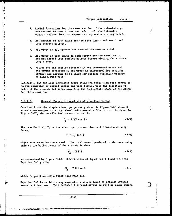
VTorque Calculation 3.3.3.
3. Radial dimensions for the cross section of the unloaded ropeare assumed to remain constant under load; the interwirecontact deformations and rope-core compression are neglected,
4, All strands in each layer are the same length and are formedinto perfect helices.
5. All wires in all strands are made of the same material.
6. All wires in each layer of each strand are the same lengthand are formed into perfect helices before closing the strands
1" into a rope.
7. Values for the tensile stresses in the individual wires andthe torque developed by the wires as calculated for straightstrands are assumed to be valid for strands helically wrappedto form a wire rope,
Basically, the analysis developed below shows the total wire-rope torque tobe the summation of strand torque and wire torque, with the direction oftwist of the strands and wires providing the appropriate sense of the signsfor the summation.
3.3.3.1. General Theory for Analysis of Wire-Rope Torque
Consider first the simple wire-rope geometry shown in Figure 3-46 where Nstrands are wrapped in a right-hand helix around a fiber core. As shown inFigure 3-47, the tensile load on each strand is
T = T/(N cos 6) (3-3)
The tensile load, T, on the wire rope produces for each strand a drivingforce,
F = Ts sin6 (3-4)i5
which acts to unlay the strand. The total moment produced in the rope owingonly to the helical wrap of the strands is then
Ms = N F R (3-5)
as determined by Figure 3-48. Substitution of Equations 3-3 and 3-4 intoEquation 3-5 yields
Ms -- T R tan B (3-6)
which is positive for a right-hand rope lay.
Equation 3-6 is valid for any rope with a single layer of strands wrappedaround a fiber core. This includes flattened-strand as well as round-strand
3-44
- - - ~ ~ -- -'-.-.-.-- -
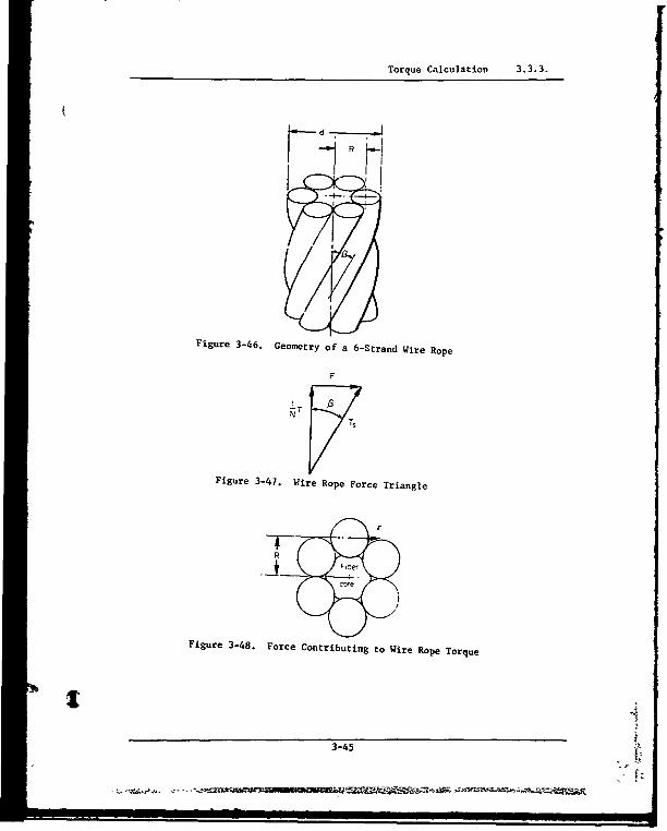
Torque Calculation 3.3.3.
~RK
Figure 3-46. Geometry of a 6-Strand Wire Rope
r
Figure 3-47. Wire Rope Force Triangle
R
Figure 3-48. Force Contributing to Wire Rope Torque
3-45

Torque Calculation 3.3.3.
ropes. For a rope with more than one layer of strands or a rope with astrand core, the calculation becomes only slightly more complicated as will )be discussed later.
Consider now a single strand under a tensile load T . This strand is com-posed of m layers of wire wrapped around either a fiber core or a wire core,all wires being made of the same material, Hruska (Ref. 3-35) has shownthat the tensile stress in the core wire may be calculated using the equa-tion,
mN
=T = N1 Aj cos3
ai) (3-7)
The tensile stres3 on the wires in any layer may then be found by
01 = c cOs 2 •i (3-8)
If the strand has a fiber core rather than a metallic core, Equation 3-7 maystill be applied by setting Ac equal to zero. The resulting numerical value,although it has no physical meaning, may then be used with Equation 3-8 todetermine the actual stress ip the other wires. Tn general, the tensilestress in the wires in the it' layer is related to the tensile stress in thewires in the jth layer by
o. = 0. (cose a. /cosa in) (3-9)
Equation 3-8 is a special case of Equation 3-9 where arc = 0.
The torque induced in the strand by the tensile load may be calculated usingthe same procedure as outlined in Equations 3-3 through 3-6. The forceacting to unlay one wire is
f, = T sin ce (3-10)
as determined by Figure 3-.,•. The total moment contribution of one completelayer of strands due only to the helical wrap of the wires is then
m
S= Ncos 8 E f, r. (3-11)i=c
or, by substitution of Equation 3-10,
mN = N cos 8 E -i A, r, sin a, (3-12)
w i=c
which is positive for a right-hand-strand lay.
The total torque developed in a simple wire rope with a fiber core may now beexpressed as the sam of the contributions of the helically wrapped strandsand the helically wrapped wires, or m 3
H= TR tan e + N cos 8 Z n, A, a. r, sin n (3-13)3-4c
1!3-46
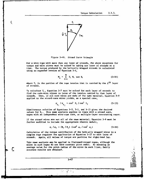
Torque Calculation 3.3.3.
( fi
a.
Twi
Figure 3-49. Strand Force Triangle
For a wire rope with more than one layer of strands, the above equations fortorque and wire stress must be solved by taking one layer of strands at atime. The torque produced by the helically wrapped strands is calculatedusing an expanded version of Equation 3-6,
mM = E T, R, tan 01 (3-14)
S i=c
where T1 is the portion of the rope tension that is carried by the ith layerof strands.
To calculate T,, Equation 3-7 must be solved for each layer of strands tofind the core-wire stress in terms of the tension carried by that layer ofstrands. Then, if all core wires are made of the same material, Equation 3-9applied to the strard-core wires yields, as a special case,
c /0 = coso 8, / cose 83 (3-15)c. c,
Simultaneous solution of Equations 3-3, 3-7, and 3-15 gives the desiredvalues for T1 . This same analysis applies to ropes with a strand core,ropes with an independent wire-rope core, or multiple-layer nonrotating ropes.
If the strand wires are not all of the same material, Equation 3-9 must befurther modified to include the appropriate elastic moduli,
a, /1 j = (E /IE.) (cos 2
os /cos' a.) (3-16)
Calculation of the torque contribution of the heli:ally wrapped wires in acomplex rope requires the application of Equation 3-12 to each layer ofstrandr. Again, all values of torque are positive for right-hand lay.
This same analysis may be applied to flattened-strand ropes, although thewires in such ropes do not have constant pitch radii. By assuming anaverage value for the pitch radius of the wires in each lyer, fairly
-% accurate results are obtained.
3-47
IM_
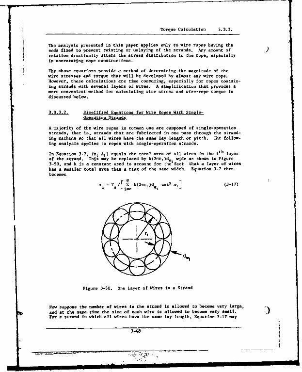
Torque Calculation 3.3.3.
The analysis presented in this paper applies only to wire ropes having theends fixed to prevent twisting or unlaying of the strands. Any amount of _F rotation drastically alters the stress distribution in the rope, especiallyin nonrotating rope constructions.
The above equations provide a method of determining the magnitude of thewire stresses and torque that will be developed by almost any wire rope.However, these calculations are time consuming, especially for ropes contain-ing strands with several layers of wires. A simplification that provides amore convenient method for calculating wire stress and wire-rope torque isdiscussed below.
3.3.3.2. Simplified Equations for Wire Ropes With Single-Operation Strands
A majority of the wire ropes in common use are composed of single-operationstrands, that is, strands that are fabricated in one pass through the strand-ing machine so that all wires have the same lay length or pitch. The follow-ing analysis applies to ropes with single-operation strands.
In Equation 3-7, (n. A,) equals the total area of all wires in the ith layerof the strand. This may be replaced by k(2nr,)dw wide as shown in Figure3-50, and k is a constant used to account for the fact that a layer of wireshas a smaller total area than a ring of the same width. Equation 3-7 thenbecomes
o= T m 3(nr)c as k(2ric )d cos ot, (3-17)-=c
dwi
Figure 3-50. One Layer of Wires in a Strand
Now suppose the number of wires in the strand is allowed to become very large,and at the same time the size of each wire is allowed to become very small, 3)For a strand in which all wires have the same lay length, Equation 3-17 may
3-48
7.(
Torque Calculation 3.3.3.
be expressed as
ac = Ts/If0 k(2irr) cos3
a dr (3-18)
From the strand geometry, it is found that 2n = A tan a. Also dr = (1/2.)sec
2 a da. Substitution of these relationships into Equation 3-18 gives
ac = 2TsTI(ke fJ sin a do (3-19)
where
X = tan-r (rds/A) (3-20)
The solutiin to Equation 3-19 is
ac/Ts = 27[ke2 (I - cos X)] (3-21)
This equation may be used to calculate the tensile stress in the core wirefor any single-operation strand in which all wires have the same lay length,A. It has been found that a value for k of 0.80 provides a good approxima-tion for most common strands. The stress in the ith layer of wires may thenbe found using Equation 3-8.
A similar technique may now be used to evaluate the torque provided by thehelically wrapped wires in one layer of strands. In Equation 3-12, let
n, A, = k(2Trrj) dwt
r= (1/2r) tan ol
and a, = ac COS 2o
The total torque developed by the wires in one layer of strands is then
MW = (kA N cos 0 ac/4Tr?) fo sin a tanr a da (3-22)
The solution of Equation 3-22 is
Mw = (k- 3 N cos 8 ac/4nP ) [(1 - cos ))
2/cos X1 (3-23)
Substitution of Equations 3-3 and 3-21 into Equation 3-23 gives the totaltorque contribution of all wires in one layer of strands,
H ff= (1/2n) (sec X - 1) T (3-24)
It has been found that for comnon wire-rope geometries, Equation 3-24 yieldsvalues of wire torque approximately 10 percent higher than the torquecalculated using Equation 3-12. This influences the value of the total wire-rope torque by only about 2 percent.,
3-49
Torque Calculation 3.3.3.
Now the total torque developed by a simple fiber-core wire rope undertensile load T may be expressed as
M = M + Mw = [(2r•R/L) + (L/2n) (sec X - 1)] T (3-25)
Again, if a complex (multiple-layered) wire rope is being considered,simplified Equations 3-20, 3-21, and 3-24 must be applied to each separatelayer of strands as was discussed earlier with regard to Equations 3-6, 3-7,and 3-12.
3.3.3.3. Simplified Equations Applied to Six-Strand Wire Ropes
Probably the most common wire-rope construction consists of six strandswrapped around a fiber core. The simplified equations may be convenientlyexpressed graphically for this type of wire-rope construction. For eitherround-strand or flattened-strand ropes, a good value for the pitch radiusof the strands is
R = 0.34 d (3-26)
Accordingly, the strand diameter is about
d = 0.32 d (3-27)
The use of Equation 3-26 in conjunction with Equation 3-6 yields the torquecontribution of the helically wrapped strands in a six-strand rope as
M /T = 2rRe/L = 0.726 d2
/L (3-28)
Figure 3-51 provides a graphical representation of Equation 3-28 and includesvalues for the strand lay angle, S. Logarithmic coordinates are used inthis figure to provide reasonable accuracy over a wide range of wire-ropegeometries. Equation 3-28 or Figure 3-51 may be used for six-strand ropeswith either single-operation or multiple-operation strands.
The tensile stress in the core wires of a six-strand wire rope may be calcu-lated using Equation 3-27 together with Equations 3-20 and 3-21. This yields
Ic/Ts = 2r-/[(kl2 (1 - cos X)] = 7.854/[12 (1 - cos X)] (3-29)
where
X = tan-1 (rds/L) =t tan-1 (d/i) (3-30)
The tensile stress in any other wire in the strand may be calculated usingEquation 3-8. The tensile stress is highest in the core wire and it is low-est in outer wires of the strand. For most common ropes, the outer wiresare stressed to at least 90 percent of the stress in the core wire,
Equation 3-30 may now be used with Equation 3-24 to evaluate the total torqueconstribution of the helically wrapped wires in a six-strand wire ropecomposed of single-operation strands. The result is shown graphically inFigure 3-52.
3-50(
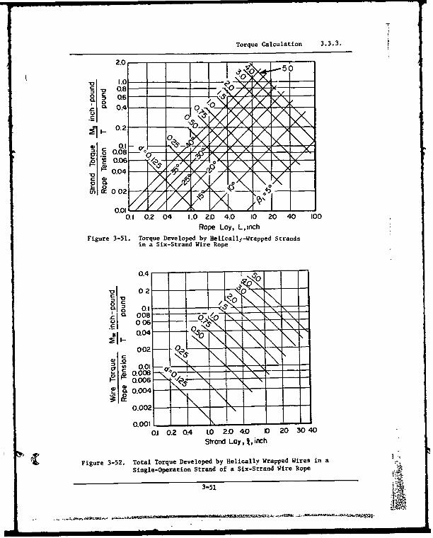
Torque Calculation 3.3.3.
1 .08
0 0.6 0.Z4Z. )4. 0 20 4 0
0.'I
0 .2-YI
01 020 0 102. 4. 203 0
St0n.04Aif~
Fiur 3-2w oa oqeDvlpdbyHlclyWapdWrsiSi0eprto StadofaSxStadWieRp
3-51 1-A
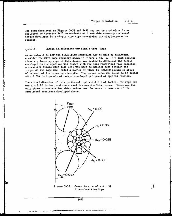
Torque Calculation 3.3.3.
The data displayed in Figures 3-51 and 3-52 may now be used directly asindicated by Equation 3-25 to evaluate with suitable accuracy the totaltorque developed by a simple wire rope containing six single-operationstrands.
3.3.3.4. Sample Calculations for Simple Wire Rope
As an example of how the simplified equations may be used to advantage,consider the wire-rope geometry shown in Figure 3-53. A 1-3/8-inch-nominal-diameter, Lang-lay rope of this design was tested to determine the torquedeveloped as the specimen was loaded with the ends restrained from rotation.A sensitive strain-gage load cell was used to monitor both tension andtorque as the rope was loaded a number of times to 100,000 pounds or about60 percent of its breaking strength. The torque curve was found to be linearwith 0.204 inch-pounds of torque developed per pound of applied tension.
The actual diameter of this preformed rope was d = 1.41 inches, the rope laywas L = 8.80 inches, and the strand lay was = 3.74 inches. These are theonly three parameters for which values must be known to make use of thesimplified equations developed above.
Fiber
cored4 =0.102
dw3 = 0 061
dw2= 0 025
dw, 0 056
dw.. 0.043
Figure 3-53. Cross Section of a 6 x 31Fiber-Core Wire Rope
3-52

Torque Calculation 3.3.3,
From Equati'a 3-28 or Figure 3-51, the torque contribution of the helically(. wrapped strands is found to be Ms = 0.164 T inch-pounds. Using Equations
3-29 and 3-30, the stress in the core wire is found to be 0c = 8.73 Ts psi.
Equations 3-24 and 3-30 or Figure 3-52 gives the total torque contributionof the helically wrapped wires as Mw= 0.041 T inch-pounds. The totaltorque produced in the wire rope is then M = Ms + = 0.205 T inch-pounds,
which is essentially identical to the measured value of 0.204 T inch-pounds.
If the same calculations are attempted using the longer method of analysis,it is necessary to first make the measurements and calculations indicated inTable 3-6. Here the wire stress is determined using Equations 3-7 and 3-8.The value obtained in this way for core-wire stress is within 2 percent ofthe value calculated using the simplified analysis.
Table 3-6. MEASUREMENTS AND CALCULATIONS FOREXAMPLEN WIRE-ROPE CONSTRUCTION
d = 1.41 inches
L = 8.80 inches
I = 3.74 inches
Number Wire Wire Pitch Layof Wires, Diameter, Area, Radius, Angle, a, °•/Ts,
Layer n dw, inch A, inch2
r, inch degrees inch'
Core 1 0.043 0.001452 0 0 8.61
1 5 0.056 0.002463 0.0495 4.75 8.55
2 5 0.025 0.000491 0.0690 6.61 8.49
3 10 0.061 0.002922 0.1040 9.91 8.35
4 10 0.102 0.008171 0.1745 16.34 7.93
Using Equation 3-12, a value for the torque contribution of the helicallywrapped wires if found to be Mw = 0.037 T inch-pounds. This is approximately10 percent lower than the value obtained using the simplified analysis. Thetotal torque produced in the wire rope is then M = Ms + N, = 0.201 T inch-pounds, which is within 2 percent of the measured value.
These sample calculations indicate that both methQds of analysis provideaccurate values for wire-rope torque. The real value of the simplifiedanalysis is that it may be used to determine the torque characteristics of aworking six-strand wire rope by measuring only the rope diameter, d; therope lay, L; and the strand lay, 1.
3.3.3.5. Measurement of Rope Lay and Strand Lay
Measurement of the rope lay can be done quire accurately by following oz.estrand along the rope for a number of turns and then dividing that length of
3-53
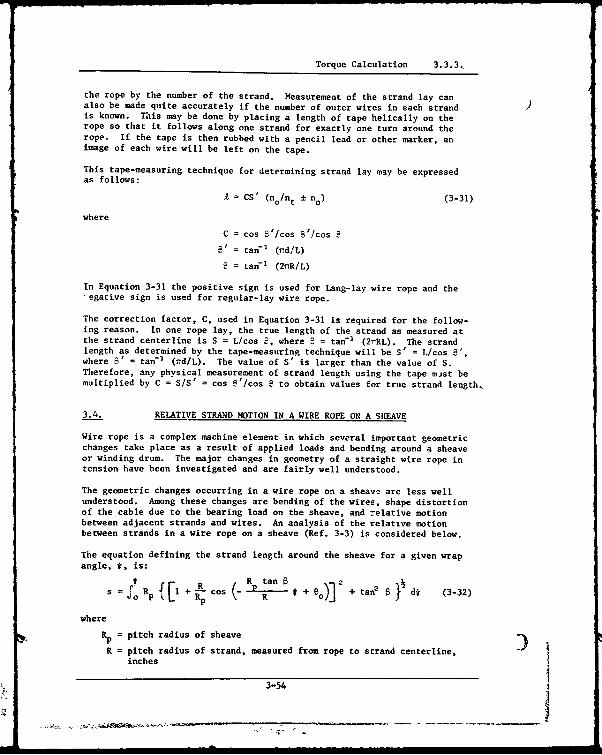
Torque Calculation 3.3.3,
the rope by the number of the strand. Measurement of the strand lay canalso be made quite accurately if the number of outer wires in each strandis known. This may be done by placing a length of tape helically on therope so that it follows along one strand for exactly one turn around therope. If the tape is then rubbed with a pencil lead or other marker, animage of each wire will be left on the tape.This tape-measuring technique for determining strand lay may be expressed
as follows:
A = CS' (no/nt ± no) (3-31)
where
C = cos B'/cos 3'/cos 9
5' = tan-' (iTdlL)
S = tan-' (21R/L)
In Equation 3-31 the positive sign is used for Lang-lay wire rope and the"egative sign is used for regular-lay wire rope.
The correction factor, C, used in Equation 3-31 is required for the follow-ing reason. In one rope lay, the true length of the strand as measured atthe strand centerline is S = L/cos S, where B = tan-r (2rRL). The strandlength as determined by the tape-measuring technique will be S' = L/cos B',where 8' = tan-' (nd/L). The value of S' is larger than the value of S.Therefore, any physical measurement of strand length using the tape mist bemultiplied by C = SIS' = cos B'/cos ? to obtain values for true strand length,
3.4. RELATIVE STRAND MOTION IN A WIRE ROPE ON A SHEAVE
Wire rope is a complex machine element in which several important geometricchanges take place as a result of applied loads and bending around a sheaveor winding drum. The major changes in geometry of a straight wire rope intension have been investigated and are fairly well understood.
The geometric changes occurring in a wire rope on a sheave are less wellunderstood. Among these changes are bending of the wires, shape distortionof the cable due to the bearing load on the sheave, and relative motionbetween adjacent strands and wires. An analysis of the relative motionbetween strands in a wire rope on a sheave (Ref. 3-3) is considered below.
The equation defining the strand length around the sheave for a given wrapangle, t, is:
SIRp f [ + CosB +eo +tan } d* (3-32)
where
Rp = pitch radius of sheave
R = pitch radius of strand, measured from rope to strand centerline,inches
3-54

Relative Strand Motion in a Wire Rope on a Sheave 3.4.
= sheave reference angle, degrees
e. = angle defining the position of a strand in a wire rope, degrees
B = strand lay angle, degrees
@o = initial angular position of a strand, degrees
s = true length of one strand as measured from the point of rope-to-sheave tangency through any specified angle, ;, inch.
In the above equation, eo determines which strand is being considered.Figure 3-54 shows the graphical result of Equation 3-32 for a six-strandrope construction. the mathematical analysis of this problem is presentedin detail in Reference 3-3.
3.4.1. Graphical Results of Strand-Motion Solution
The results of the analysis are presented in generalized form here. Theparameters necessary in evaluation of the magnitude of the motion betweenadjacent strands are the ratio of the rope lay length to the rope diameter,I/d; the ratio of the sheave pitch diameter to the rope dis,,eter, D/d;, andthe rope diameter, d. The rope lay length is the distance required for eachstrand to complete one turn of its helix abojt the axis of the rope. Oncethese parameters are known for a particular rope and sheave, Figure 3-55 canbe used to determine the mi-:imum relative strand motion, Asmax. This is doneby finding the point on the left half of the figure which corresponds to theparticular values of A/d and D/d. This point is then projected horizontallyto the right until the line corresponding to the rope diameter, d, is inter-sected. Then the corresponding value of Lsnax is read on the right horizontalaxis.
For a 1-3/8-inch, 6 x 25 filler-wire, round-strand wire rope on a 24-inchsheave, the interatrand motion is found as shown below. The actual diameterof a typical rope is 1.46 inches, and the lay length is 9.5 inches. Thusthe ratio of lay length to rope diameter. AId, is 6.50, and the sheave-to-rope diameter ratio D/d is 16.4. This gives a maxim'um strand motion, Asmaxof about 0.11 inch,
In Reference 3-3 an attempt was made to measure experimentally the strandmotion for the 1-3/8-inch rope -w~ntioned above. Mo valid results wereobtained becau.- of the high ropE friction and because of distortion in thefree end of the cable where the measurements were bein6 'ace.
3.4.2. Discussion and Further Implications ef theStr,, d-Motion Solution
Six-strand wire ropes are of greatest current interest to the Navy, there-fore, the graphs in this section are plotted only for six-strand wire-ropeconstructions. The results are also valid for single strands having sixwires over a core. However, it should be emphasized that the solution
*presented in Reference 3-3 is perfectly general and, therefore, is applicableto any construction. It should also be noted that a slight error resultsif Figure 3-55 is applied to flatteneJ-strand constructions. This error
3-55
W 75_
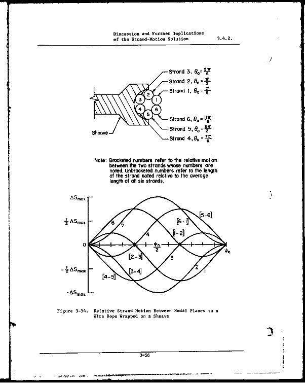
Discussion and Further Implicationsof the Strand-Motion Solution 3.4.2.
9
Strand 3, 0o= 6-
Strand 2, 8o =-!-
Strand I, 0o . 76F
4 6Strand 6, 0 =L
4Sheave- Strand 5, 00o= 27-
Strand 4, 6 o --'X
Note: Bmcketed numbers refer to the relative motionbetween the two strands whose numbers arenoted. Unbracketed numbers refer to the lengthof the strand noted relative to the averagelength of all six strands.
ASmax -
-A ASmax
-ASmax L
Figure 3-54. Relative Strand Motion Between Nodal Planes in aWire Rope Wrapped on a Sheave
3-56
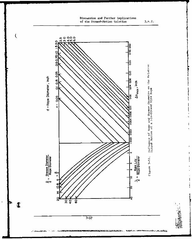
Discussion and Further Implicationsof the Strand-Motion Solution 3.4.2.
(d (
0IrI0= 0
to
V mig.
0-
.r_ In
Sts
•Sn
- afl* °.•~tC
d 1C
ci
• 0 00
3-57 0
*= = ,, = = == • --
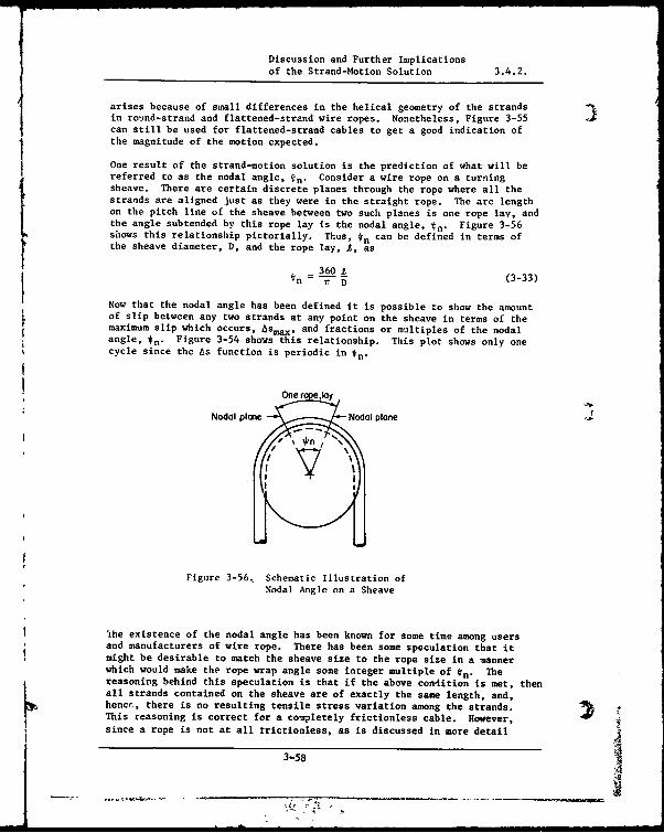
Discussion and Further Implicationsof the Strand-Motion Solution 3.4.2.
arises because of small differences in the helical geometry of the strandsin round-strand and flattened-strand wire ropes. Nonetheless, Figure 3-55can still be used for flattened-strand cables to get a good indication ofthe magnitude of the motion expected.
One result of the strand-motion solution is the prediction of what will bereferred to as the nodal angle, *n" Consider a wire rope on a turningsheave. There are certain discrete planes through the rope where all thestrands are aligned just as they were in the straight rope. The arc lengthon the pitch line of the sheave between two such planes is one rope lay, andthe angle subtended by this rope lay is the nodal angle, tn. Figure 3-56shows this relationship pictorially. Thus, tn can be defined in terms ofthe sheave diameter, D, and the rope lay, 1, as
360OAtn = -T- (3-33)
Now that the nodal angle has been defined it is possible to show the amountof slip between any two strands at any point on the sheave in terms of themaximum slip which occurs, Asmax, and fractions or multiples of the nodalangle, tn. Figure 3-54 shoas this relationship. This plot shows only onecycle since the ts function is periodic in tn-
One rope,lay
Nodal plane Nodal plane
itI
Figure 3-56, Schematic Illustration ofNodal Angle on a Sheave
1he existence of the nodal angle has been known for some time among users* and manufacturers of wire rope. There has been some speculation that it, might be desirable to match the sheave size to the rope size in a manner
which would make the rope wrap angle some integer multiple of *n" Thereasoning behind this speculation is that if the above condition is met, thenall strands contained on the sheave are of exactly the same length, and,hencr, there is no resulting tensile stress variation among the strands.This reasoning is correct for a completely frictionless cable. However,since a rope is not at all trictionless, as is discussed in more detail
3-58

Discussion and Further Implicationsof the Strand-Motion Solution 3.4.2.
below, the strand motion actually takes place in the straight portion of therope adjacent to the sheave, and the strands are stationary once they are onthe sheave. Therefore, there is no means available to communicate from oneend of the rope what the conditions are at the other end. In other words,once the rope is on the sheave and interstrand motion is stopped, it doesnot satter how far the rope travels before it leaves the sheave. Thus, itcan be concluded that the condition that the rope wrap angle be some integermiltiple of the nodal angle has an insignificant effect on operation andexpected life.
It is desirable, however, to reduce the magnitude of relative strand motionfor several reasons, This motion causes the wires in the cable to wear atthe contact points. Recalling that these contact points are the same pointsat which the very high contact stresses occur illustrates the importance ofminimizing the motion. Another result of the motion is friction-inducedheating. At high tensile loads and high rope velocity, the rope may becomequite hot and melt off the protective lubricant, thus interfering with properrope lubrication. With the lubricant gone from the contact points the wearproblem is compounded, Preliminary calculations show that most of the energyrequired to cycle a rope around a sheave can be accounted for by consideringonly the friction-induced heat energy released as a result of the predictedinterstrand motion.
Reference to Figure 3-55 indicates the important parameters involved from adesign standpoint in reducing interstrand motion. It is easily seen that areduction in the ratio of rope lay to rope diameter, L/d, produces acorresponding reduction in ASmax' It should also be noted that a redzctionin this ratio is beneficial from the standpoint of wire-bending stress. How-ever, there is a design trade-off here in that the smaller L/d becomes, thelower are the ultimate strength and elastic moudlus of the rope. Thisindicates that there may be some optim'Jm value of I/d for a given applica-tion. An increase in the ratio of sheave diameter to rope diameter, D/d,also decreases Asmax. The only upper limit on this ratio is one of spaceavailability. Although a change in the coefficient of friction in the ropewill affect asmax very little, lower friction would alleviate some of theundesirable effects such as cable and sheave heating associated with strandmotion. Heating in a properly aligned bheave is actually a result of heattransfer from the rope ta the sheave.
Since friction is inherent in all wire rope, and since it is one factor whichcomplicates the experimental determinition of relative strand motion, thequestior ariqes as to the effect of friction on relative strand motion in awire rope ii. actual service. Two things can be said in general about aworkiog wire rope in this respect.
Observations of wire rope tested on a Battelle wire-rope fatigue machine(Ref. 3-3) have shown that a very large part of the interstrand motion takesplace in the stragith section of the rope quite near the point of ropetangency on the sheave. Also, due to the bearing loads of the rope on thesheave, the interstrand contact force and, thus, the internal rope frictionincreases considerably as the rope wraps onto the sheave.
SThe friction forces in the straight section of a 1-3/8-inch wire rope were .7computed and compared to the forces that would be required to prevent the
~~~~- , I II I3-59 A

4 Wire Rope Stress Analysis 4.
4.( WIRE ROPE STRESS ANALYSIS
A nun-br of investigators (Refs. 3-8, 3-15, and 4-1) discuss the difficultyor even the impossibility of accurately computing the stresses in a wirerope. (Some of these same investigators then attempt the analysis them-selves with no better apparent success than those that preceded them.)Nevertheless, efforts to derive equations that will permit a wire-ropedesigner to rationally predict the relationship between the conditionsimposed on a rope, the stresses produced, and the resultant rope life con-tinue. No one has succeeded to date primarily because of the complexnature of the stress field present in the wires of a rope and its sensitiv-ity to external factors that are extremely difficult to identify accurately,such as friction and wire surface condition.
The induced stresses that are normally present in a loaded wire rope aretensile, bending, shear, compressive, contact or "Hertzian", and torsion.To further complicate the problem, there are normally residual stresseswhich have been introduced in the manufacturing process. Both the construc-tion of the rope and its usage conditions dictate which of the stressespredominate.
In this presentation no attempt is made to give the derivation of the equa-tions or all of the assumptions that were made with the single exception ofthe bending stress analysis. The interested reader should consult the citedreferences for more detailed analyses.
4.1. TENSILE STRESS
The tensile stress in an individual wire in a straight wire rope, neglectingradial contraction of the rope under axiGl loading and internal friction,is given by (Refs. 3-35 and 4-2):
r =a COS2011,
(4-1)
cc = T /A Cos e + ----- "A cos3 a, + ... n.A, cos3 Cf) (4-2)
Ts = T/ms cos 8 (4-3)
Combining:
T cosa at
OI ma cos 8 (A cosa 8 + n1A1 cosa3
o + ... n1A1 cos3
cil (4-4)
where
as = tensile stress in wires in layer i, Ib/in2
or tensile stress in core wires, Ib/in3
a, lay angle of wire layer i, degrees
4-1
Tensile Stress 4.1.
= lay angle of strands, degree
A, = area of individual wires in layer i, in2
Ac = area of core wire, in'
T = tensile force on rope, lbT = tensile force on strand, lb
m = number of strands
n, = number of wires in layer i.
4.2. BENDING STRESS
Over the years, many attempts have been made to compute (or estimate) thebending stresses in a wire rope. These analyses have ranged from simplisticto extremely complex, Many wire-rope manufacturers and users regard theproblem as insolvable. Indeed, until the advent of large computers, theproblem was nearly so. To illustrate the diverse formulas that have beensuggested in the past, Table 4-1 (Ref. 4-1) presents some of them and com-rares their results.
Currently, several attempts are in progress to solve the problem usingfinite-element analysis techniques. Another analysis involving methods ofvector analysis and strength of materials has been completed (Ref. 4-3) andis reproduced hiere.
To analyze the bending stresses in the wires of a rope, it is first necessaryto determine the radii of curvature of the wires prior to and after bendingthe rope. The wire-bending stress can then be calculated from the change inwire curvature. The purpose of the following analysis is to present a pro-cedure for computing the radii of curvature of the wires both in a straightrope and in a rope wrapped on a sheave and determining the resultant bendingstresses.
The complexity of the equations generated in the analysis requires nuutericalresults in order to be viewed meaningfully. Therefore, all numerical resultswere obtained using the parameters of a 1-3/8-inch-diameter, 6 x 25 fillerwire, Lang-lay, round-strand wire rope, which is referred to hereafter asthe Standard Rope.
4.2.1. Analysis of a Straight Wire Rope
4.2.1.1. Wire-Rope Geometry
Figure 4-1 shows a typical Lang-lay, wire-rope construction in which boththe wire and strand wraps conform to a right-hand rule. Another cmmon con-figuratian is regular-lay construction which differs from Lang-lay only inthat the wire wrap is opposite the strand wrap. The analysis presented belowis specifically for a Lang-lay rope but can easily be adapted to regular-layby noting the change in geometry.
4-2
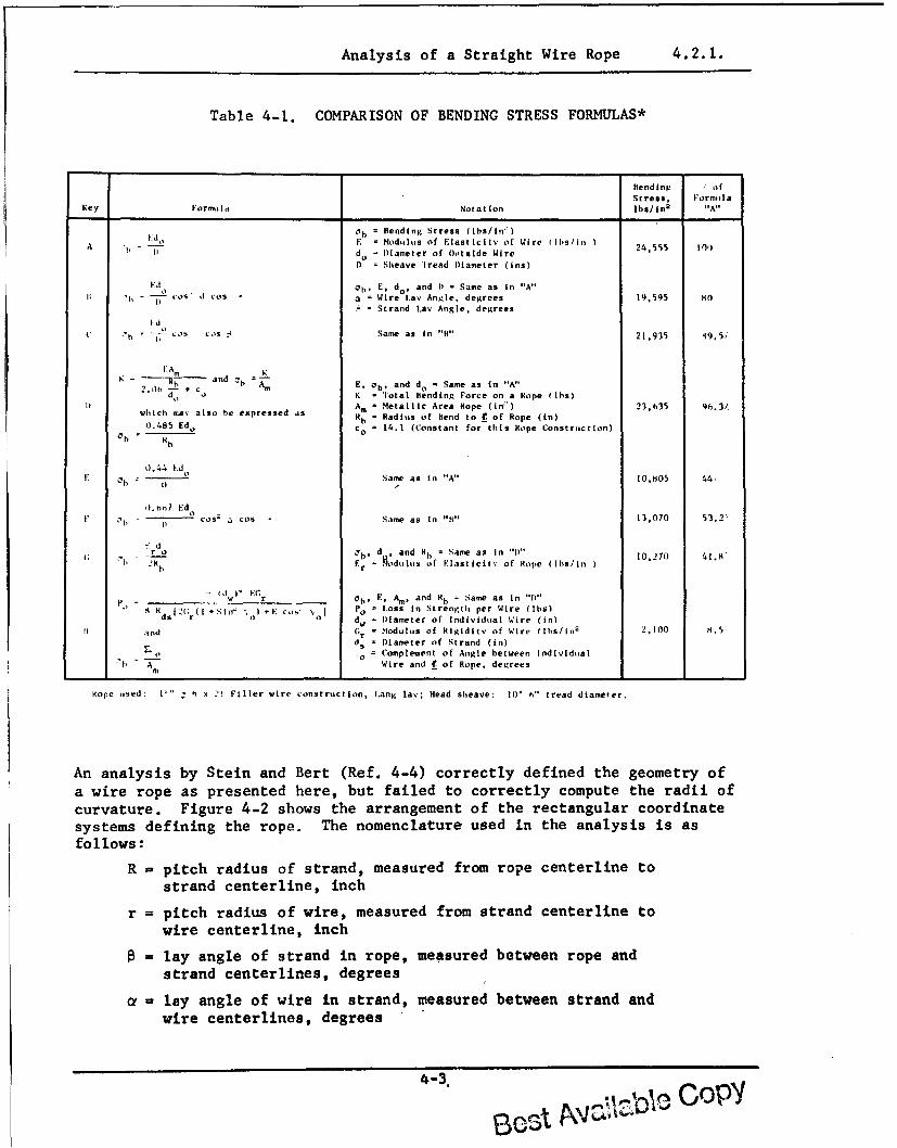
Analysis of a Straight Wire Rope 4.2.1.
Table 4-1. COMPARISON OF BENDING STRESS FORMULAS*
Rend inw *' of
Stress . Form,,IaKey Formo la Notation Ibs/inn
2 A"
0d = Bending Stress (Ibs/in')
A E - Modulus of Elasticitv of Wire (Is/in 24,555 lA do a Diameter of Outside Wire
D ) Sheave tread Diameter (ins)
,. - oh. E, do,a'.nd it ;,Same as in "A".h --°S- d C'os a . Wire L Angle, degrees 19,595 go
= Strand Lay Angle, degreesid
t, 0 - .os Ios C' Same as in "B" 21,935 '49.5,
K FAm adc Kot AR an E. ob, and do - Same as in "A"
d' c K - Total Bending Force on a Rope (ihs)
I htAm l Metallic Area Rope (in:') 23,635 9b.3/which ma4 also he expressed as Rb - Radius of Bend to f of Hope (in)0.485 Edo c -= 14.1 (Constant for this Rope Construction)
0.44 Ed
F Same as in "A" 10,H05 44,
0.n,7 Ed
- Cos' a COS Same as in "B" 13,070 53.2"
K d"rr ao' d , and III, Same as in "1)" 10,270 41.8
2K IR F.= r ?odal,.s of Elasticity of Hope (lIs/in:
- (Iw)' EC'r Oh. E. Am. and R. - Same as in "It"8 R ( .1Gr(I +Sin' ,) +E cos Po z Loss in Strength per Wire (Ibs)
0 0 dw = Diameter of Individual Wire (in)
and (;r - Modulus of Rigiditv of Wire (lbs/in2
-,0oo (1.5'
ds - Diameter of Strand (in)
0'o = Complement of Angle between Individual"-h A--m Wire and f of Rope, degrees
Rope used ' x .1 Filler wire construction, Lang lav; Head sheave: 10' h" tread diameter.
An analysis by Stein and Bert (Ref. 4-4) correctly defined the geometry of
a wire rope as presented here, but failed to correctly compute the radii of
curvature. Figure 4-2 shows the arrangement of the rectangular coordinatesystems defining the rope. The nomenclature used in the analysis is asfollows :
R = pitch radius of strand, measured from rope centerline to
strand centerline, inch
r = pitch radius of wire, measured from strand centerline towire centerline, inch
= lay angle of strand in rope, measured between rope andstrand centerlines, degrees
a= lay angle of wire in strand, measured between strand andwire centerlines, degrees
4-3.
£~~O~~b 0W2Z CO'P'
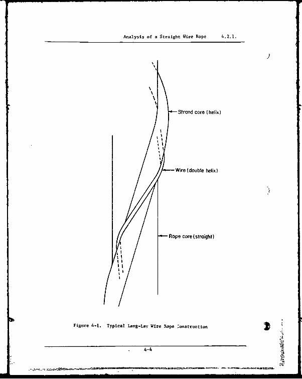
Analysis of a Straight Wire Rope 4.2.1.
Strand core (helix)
Wire (double helix)
Rope core (straight)
, / I
Figure 4-1. Typical Lang-Lay Wire Rope :onstruction
4-4
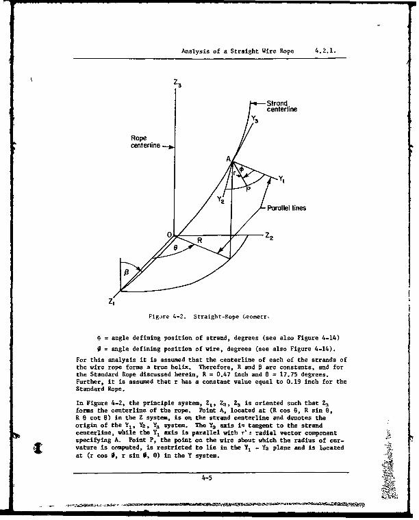
Analysis of a Straight Wire Rope 4.2.1.
k Z3
Strandcenterline
Y3
Ropecenterline
A
YlP
Y2Parallel lines
R Z2
Z'
Figaire 4-2. Straight-Rope Geometr'
o = angle defining position of strand, degrees (see also Figure 4-14)
0 = angle defining position of wire, degrees (see also Figure 4-14).
For this analysis it is assumed that the centerline of each of the strands ofthe wire rope forms a true helix. Therefore, R and 0 are constants, and forthe Standard Rope discussed herein, R = 0.47 inch and 0 = 17.75 degrees.Further, it is assumed that r has a constant value equal to 0.19 inch for theStandard Rope.
In Figure 4-2, the principle system, Z,, Z2 , 73 is oriented such that Z3forms the centerline of the rope. Point A, located at (R cos 8, R sin 0,R 0 cot 8) in the Z system, is on the strand centerline and denotes theorigin of the Y,, Y2, Y3 system. The Y3 axis iq tangent to the strandcenterline, while the Y, axis is parallel with r'a radial vector componentspecifying A. Point P, the point on the wire about which the radius of cur-vature is computed, is restricted to lie in the Y, - Y2 plane and is locatedat (r cos 0, r sin 0, 0) in the Y system.
4-5
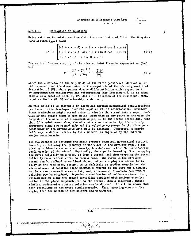
Analysis of a Straight Wire Rope 4.2.1.
4.2.1.2. Derivation of Equations
Using matrices to rotate and translate the coordinates of P into the Z system(see Section 5.1.) gives
.[((R + r cos 0) cos • - r sin 0 cos : sin e)]
z (R + r cos 0) sin e + r sin 0 cos cos :1 (4-5)
LR S cot S - r sin 0 sin) ;)
The radius of curvature, p. of the wire at Point P can be expressed as (Ref.4-5)
V X ,1.5= (4-6)(V' x Z")[ -v,
where the numerator is the magnitude of the first geometrical derivative of[Z , squared, and the denominator is the magnitude of the second geometricalderivative of iZ1, where primes denote differentiation with respect to r.By computing the derivatives and substituting into Equation 4-6, it is foundthat o is a function of 0, 9, 0 ', and 0 ''. Solution of the ecuations, then,requires that a (0, 9) relationship be derived,
At this point it is desirable to point out certain geometrical considerationspertinent to the development of the required (0, 9) relationship. Considerfirst a single straight strand prior to closing the strand into a rope. Eachwire of the strand forms a true helix, such that at any point on the wire thetangent to the wire is at a conscant angle, Y. to the strand centerline. Notethat if a point moves along the wire at a constant velocity, its velocitycomponent along the strand axis and its velocity component in the plane per-pendicular to the strand axis also will be constant. Therefore, a simplehelix may be defined either by the constant lay angle or by the uniform-motion consideration.
The two methods of defining the helix produce identical geometrical results.However, in defining the geometry of the wires in the straight rope, a per-plexing problem is encountered; namely, how does one define the double-helixconfiguration of the wires? Physically, the rope is formed by first wrappingthe wires helically on a core, to form a strand, and then wrapping the strandhelically on a central core, to form a rope. The wires in the straightstrand can be defined as cutlined above. After wrapping the strand heli-cally on the rope core, though, it is difficult to predict exactly how thewires behave. A constant angle between a tangent to the wire and a tangentto the strand centerline may exist, and, if assumed, a radius-of-curvaturesolution may be obtained. Assuming a combination of unfform motions, i.e.,uniform motion along the strand centerline combined with uniform circularmotion in the plane perpendicular to the strand, then a different, thoughsi.'milar, radius-of-curvature solution can be derived. It will be shown thatboth conditions do not exist simultaneously. Thus. assuming constant layangle, then the motion is not uniform a.d vice-versa.
4-6

Analysis of a Straigt Wire Rope 4.2.1.
It is possible, perhaps probable, that both varying angle and nonuniformmotion conditions exist simultaneously in a real rope; however, making thisassumption does not lend enough constraints for solving the problem. Of thepossible combinations of angle and motion assumptions, then, only two areacceptable for analysis, and, since either of these seems equally likely tooccur, the problem will be solved for each case.
The required (0, 0) relationships for the two solutions may be derived asfollows. Note that, in the Z-system, the tangent to the wire double-helixcurve at P and the tangent to the strand simple-helix curve at A have be-tween them the wire lay angle, (Y. Thus, the scalar dot product of the twotangents is
A-' = I'1 IK'1 cos a (4-7)
where= tangent to double-helix curve
A' = tangent to helix curve,
Substituting derivatives yields the differential equation,
0' + cos 5 = R tan a + tan o sin 3 cos 0 (4-8)rasin B
Refer to Section 5.2. for the details of obtaining Equation 4-8 from 4-7.
4.2.1.2.1. Constant Angle Assumption.
First, consider the constant-angle assumption. If a is constant, thenEquation 4-8 may be written as
01 + c = a + b cos0 (4-9)
where a, b, c are the appropriate constants, Of the several solutions toEquation 4-9 (Ref. 4-9), only one case, (a - c)3 > bV, satisfies the physicalsituation for real wire-rope parameters (o, 9, R and r) and, thus, the cor-rect relation is
2 tan-' a - c - b tan + K, (4-10)1 (a - 02e -b 'A s - c • K- (4 10
where K, may be evaluated per initial conditions. Also,
0" = -b0' sin 0 (4-11)
follows readily from Equation 4-9.
Figure 4-3 displays graphically the (0, 9) relationship given by Equation4-10. It is important to notice that the slope is not constant, but fluc-tuates about the "average slope" line as shown. The magnitude of thefluctuation is small, but the important consideration is that many terms inthe second derivatives of the equations for radius of curvature take onsignificant magnitudes.
4-7 1-
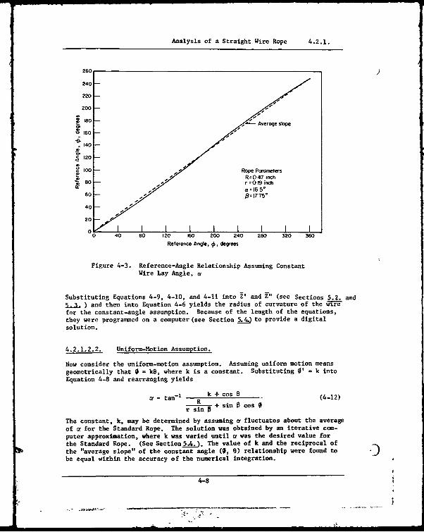
Analysis of a Straight Wire Rope 4.2.1.
260
240
220-
200
0Average slope
S160 -
"1 40
.20
S o00 -- Rope Parameters*yR='047 ,ichZ 80- r 0o19 inc
-0 " a 16 5*60 - 8=1775o
40 - -
20o . I I I I I I0 40 s0 120 160 200 240 280 320 360
Reference Angle, q, degrees
Figure 4-3. Reference-Angle Relationship Assuming ConstantWire Lay Angle, a
Substituting Equations 4-9, 4-10, and 4-11 into 2' and D" (see Sections 5.2. and5" ) and then into Equation 4-6 yields the radius of curvature of the wir"for the constant-angle assumption. Because of the length of the equations,
they were programmed on a computer (see Section 5) to provide a digital
solution.
4.2.1.2.2. Uniform-Motion Assumption.
Now consider the uniform-motion assumption. Assuming uniform motion means
geometrically that 0 = k6, where k is a constant. Substituting 0' = k into
Equation 4-8 and rearranging yields
a = tan- R k + cos 5 (4-12)
R sin B + sin 8 cos 0
The constant, k, may be determined by assuming a fluctuates about the average
of a for the Standard Rope. The solution was obtained by an iterative com-
puter approximation, where k was varied until a was the desired value forthe Standard Rope. (See Sectionn5.). The value of k and the reciprocal of
the "average slope" of the constant angle (0, e) relationship were found to
be equal within the accuracy of the numerical integration.
4-8
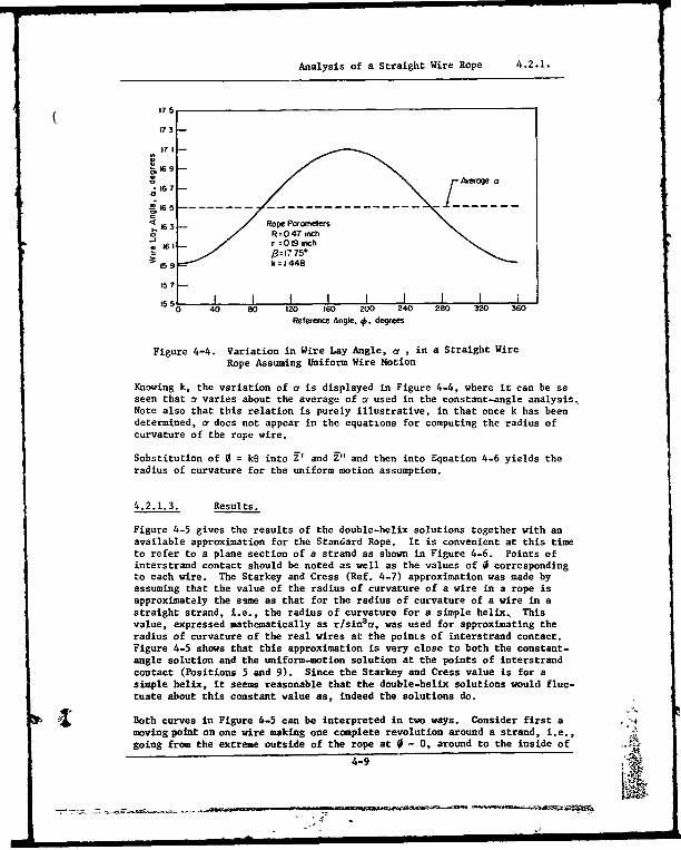
Analysis of a Straight Wire Rope 4.2.1.
175
1763
E 165
15 7
I I I I I I I I0 40 80 20 60 200 240 280 30 6Referenc -Ang-e. -. degrees
Figure 4-4. Variation in Wire Lay Angle, a , in a Straight WireRope Assuming ifors Wire Motion
Knowing k, the variation of a is displayed in Figure 4-4, where it can be seseen that a varies about the average of a used in the constant-angle analysis.Note also that this relation is purely illustrative, in that once k has been
determined, af does not appear in the equations for computing the radius of
curvature of the rope wire.
Substitution of 0 = k6 into V and Z" and then into Equation 4-6 yields the
radius of curvature for the uniform motion assumption.
4.2.1.3. Results.
Figure 4-5 gives the results of the double-helix solutions together with an
available approximation for the Standard Rope. It is convenient at this time
to refer to a plane section of a strand as shown in Figure 4-6. Points ofinterstrand contact should be noted as well as the values of 0 correspondingro each wire. The Starkey and Cress (Ref. 4-7) approximation was made by
assuming that the value of the radius of curvature of a wire in a rope isapproximately the sane as that for the radius of curvature of a wire in a
straight strand, i.e., the radius of curvature for a simple helix. Thisvalue, expressed mathematically as r/sinefa, was used for approximating the
radius of curvature of the real wires at the points of interstrand contact.Figure 4-5 shows that this approximation is very close to both the constant-angle solution and the uniform-motion solution at the points of interstrand
contact (Positions 5 and 9). Since the Starkey and Cress value is for a
simple helix, it seems reasonable that the double-helix solutions would fluc-
tuate about this constant value as, indeed the solutions do.
S •I ~Both curves in Figure 4-5 can be interpreted in two ways. Consider first a , *
moving point on one wire making one complete revolution around a strand, i.e.,going from the extreme outside of the rope at 0 0 , around to the inside of',4-9 =
16 II I I I| I I I I l
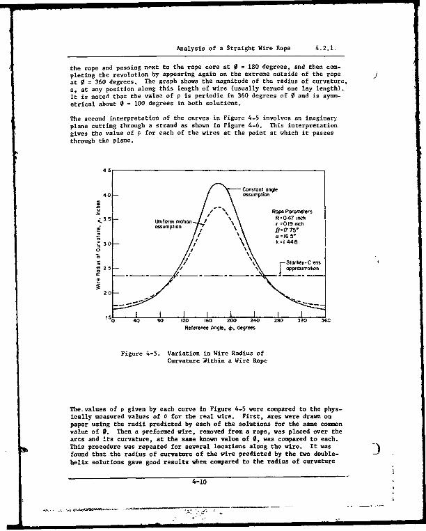
Analysis of a Straight Wire Rope 4.2.1.
the rope and passing next to the rope core at 0 = 180 degrees, and then com-pleting the revolution by appearing again on the extreme outside of the ropeat 0 = 360 degrees. The graph shows the magnitude of the radius of curvature,o, at any position along this length of wire (usually termed one lay length),It is noted that the value of p is periodic in 360 degrees of 0 and is symmn-etrical about 0 = 180 degrees in both solutions.
The second interpretation of the curves in Figure 4-5 involves an imaginaryplane cutting through a strand as shown in Figure 4-6. This interpretationgives the value of P for each of the wires at the point at which it passesthrough the plane.
-Constan~t angle4 0 assumption
S Rope Porometers35- R=047 inch•
Uniform motion r = 0R19 inchOassumption 8217 T5*
30- k-1448
0 JI/" Stor key- C "ess
2 5 -- opprox-hIon
20
0 40 so 120 160 200 240 280 3?0 36Reference Angie. 4'. degrees
Figure 4-5. Variation in Wire Radius ofCurvature Within a Wire Rope
The.values of p given by each curve in Figure 4-5 were compared to the phys-ically measured values of 0 for the real wire. First, arcs were drawn onpaper using the radii predicted by each of the solutions for the same commonvalue of 0. Then a preformed wire, removed from a rope, was placed over thearcs and 4ts curvature, at the same known value of 0, was compared to each.This procedure was repeated for several locations along the wire. It wasfound that the radius of curvature of the wire predicted by the two double-
helix solutions gave good results when compared to the radius of curvature
4-10

Analysis of a Straight Wire Rope 4.2.1.
Y,
0=330° 0=30-
II I 3
2-40° %6=1200
' Point ofinterstrund\\ 8 6 / contact
\0 =2100 1500/\ ,• = 180o /
\I\ /
i o /\ /\/\ /\ /
\/\ /
\ /' /
Origin of Z- System
Figure 4-6. Plane Section of a 6 x 25 Filler-Wire Strand
i-41
|4-11

Analysis of a Straight Wire Rope 4.2.1.
of real wire at all points along the length of the wire, but that it was notpossible to make measurements with the accuracy reqdired to determine the )correct solution.
An interesting demonstration of the validity of the assumed vire.rope geom-etry can be made by observing the geometric pattern that a wire projectsonto the Z, - Z, plane, and comparing it with the pattern seen by lookingalong the Z3 axis of a wire removed from a preformed wire rope. The valuesused for these coordinates (Z1 , Z2) can be obtained from either double-helixsolution. Figure 4-7 represents the Z. - Z4 plot for the Standard Rope. Inthis construction, both the wires and the strands are wrapped in right-hand
Z2
07 0
06Wire
05i centerline
Strand - - 0,4centerline
0. "
/ 03/\
02-
oi-\I I I I I
0 0.1 0.2 0.3 04 0.5 0.6 0.7Z'
Rope Parameters-R =O.47 inchr =0.19 inchR=17.750a = 16 5*k =1.448
Figure 4- . Illustration of Wire Position in the Standard RopeRelative to the Z- 7 Coordinate ,•vstem
4-12

Analysis of Straight Wire Rope 4.2.1.
helices. It was noted that upon looking down the length (along the Z3 axis)( of a preformed Lang-lay wire, the same geometric pattern as shown in Figure
4-7 was observed. Further, for measurement purposes, there is no appre-ciable difference in the geometries generated by application of the constant-angle and uniform-motion assumptions. In other words, the difference in thegeometries cannot be measured on an actual rope, thus eliminating actualmeasurement as a method of determining which solution provides the resultsmost nearly matching a real rope.
As a further check on the validity of the solutions, the wire lay angle, a,was varied to confirm that as a approaches some small finite value, the wiregeometry becomes that of a simple helix. Considering first the uniform-mot-ion solution, substituting k = 0 into the appropriate equations will yieldthe geometry of a simple helix. This can be seen most easily by referringto the straight rope geometry, Figure 4-2, Physically, letting k = 0 pro-duces a rope geometry such that any outer wire maintains its same positionin the strand along the length of the rope.
On first thought, it might seem that for k = 0 the wire lay angle, o, is alsozero and that both the wire and strand centerlines are at angle 9 to the ropecenterline. However, setting k equal to zero in Equation 4-12 yields a valuefor a of approximately 6.45 degrees for the outer wire at 0 = 0 in the Stan-dard Rope. That such a small, nonzerc a actually exists for k = 0 can beeasily verified by viewing the simple-helix geometry. The strand centerlinelies at angle 8 to the rope centerline and has pitch radius R. The laylength of the strand is defined as the distance that the strand covers alongthe rope centerline for one revolution of 6, and is equal to RB/tan B asshown in Figure 4-8. With the wire parallel with the strand centerline, thewire also takes the geometry of a simple helix with a pitch radius of R + rfor the outer wire at 0 - 0. For any given 6, the lay lengths of wire andstrand are equal, and 8, can be written as
B tan-'R + r.)(4-13)
For the Standard Rope, B' = 24.20 degrees. The wire lay angle, a, can befound by noting that a = 9' - 9, at 0 = 0. This yields a = 6.45 degrees,which equals the value of a predicted by the uniform-motion solution fork 0.
Also, the value of radius of curvature, p, predicted by the uniform motionsolution, at 0 = 0, k = 0, exactly equals the p calculated for a simplehelix of radius R + r and lay angle B'. This value of p is computed as(R + r)/sin
2 B' and is equal to 3.93 inches.
As at is varied in the constant-angle solution, a singularity occars in the(0, 0) relationship. The (a - c)2
> b2 condition used to determine Equation
4-10 does not hold true between 6.45 degrees and 6.95 degrees, thus changingthe form of the relationship (Ref. 4-6). The arc tangent in Equation 4-10becomes either the inverse hyperbolic tangent or cotangent depending onwhether the magnitude of its argument is more or less than one. When themagnitude of the argument is one, then the inverse hyperbolic grows infin-ite, something which is not consistent with rope geometry.
4-13
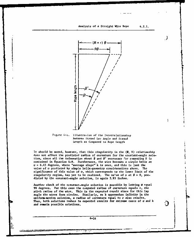
Analysis of a Straight Wire Rope 4.2.1.
----- (R + r) 8---
RO 79
~ / /
4/CL
1,/Il/ i
Figure 4-o. Illustracion of the InterrelationshipBetween Strand Lay Angle and StrandLength as Compared to Rope Length
It should be noted, however, that this singularity in the (0, 0) relationshipdoes not affect the predicted radius of curvature for the constant-angle solu-tion, since all the information about 0 aud 01' necessary for computing 0 iscontained in Equation 4-9. Furthermore, the wire becomes a simple helix ata = 6.45 degrees, where "average slope" k is zero, and this is lust thevalue of a predicted by simple helix-geometry considerations above. Thesignificance of this value of a, Phich corresponds to the lower limit of thesingularity region, has yet to be realized. The value of p at 0 - 0, pre-dicted by the constant-angle solution, is again 3.93 inches.
Another check of the constant-angle solution is possible by letting a equal90 degrees. For this case the computed radius of curvature equals r, thepitch radius of the wire. This is the expected result since for this layangle the wires form circles. Similarly, as k approaches infinity in theuniform-motion solution, a radius of curvature equal to r also results.Thus, both solutions reduce to expected results for extreme cases of a and kand remain possible solutions.
4-14
I ' - Ij I I I I

I lAnalysis of Straight Wire Rope 4.2.1.
As was stated earlier in this report, the analysis is presented specificallyfor a Lang-lay rope. However, it is now simple to obtain the solutions fora regular-lay construction by noting a sign change.
For the constant-angle solution, substituting a negative a into Equations 4-7through 4-11 makes them correspond to equations for a regular-lay rope.Thus, the (0, 0) relationship is modified slightly, but is still the samegeneral form as in Figure 4-3. The most interesting aspect, though, is thatthe radius-of-curvature plot is unchanged from that displayed in Figure 4-5.
Similarly, a solution for regular-lay rope may be obtained by substituting0= -ke into the uniform-motion-solution equations for radius of curvature.Again, the same radius-of-curvature plot is obtained for both Lang-lay andregular-lay ropes provided that the two values for k are chosen to corres-pond to the same magnitude of average a. Note that for the same magnitudeof average a for Lang-lay and regular-lay ropes, the magnitudes of tbe k's aredifferent. For example, when average a in the regular-lay rope k = -3.355.This is true since zero k occurs at nonzero a. Figure 4-9 displays the
I 6
5 -
Regular - lay Long - lay
3 -wire rope~ wire rope
Cý
S-2
Rope Parameters.-4 R =0.47 inch
r= 0.19 inch-5 17.75*
-6
-7- _ __ _ __ _ __ _I I I
-40 -30 -20 -10 0 10 20 30 40
Wire Lay Angle, a, degrees
Figure 4-9. Relationship Between Wire Lay Angle andthe Constant of Motion.
4-15
Analysis of a Wire Rope Wrapped on a Sheave 4.2.2.
relationship of k to a for both regular-lay and Lang-lay ropes. The curveis valid for either the .
4form-motion solution (k versus average a).
While varying a to make the preceding checks on the radius of curvature solu-tions, an unexpected sensitivity to a was noted in p, Figure 4-10 shows afamily of curves for radius of curvature from the constant angle solution asa function of the wire lay angle, a, for various values of 0. When it isrealized that a is the most difficult parameter in the rope to measure, theimportance of Figure 4-10 becomes apparent. For instance, a one-degreeerror in measuring ar for the Standard Rope can result in as much as a 27percent error in the value of p at 0 = 180 degrees,
A similar family of curves for the uniform-motion solution is shown in Fig-ure 4-11. Both the constant-angle and uniform-motion solutions predict asingularity at 0 - 180 degrees for a approximately 11 degrees, or k approxi-mately 0.5. Since the singularity predicts a straight segment of wire atthis point, this seems entirely reasonable.
Since the radius-of-curvature plots, Figure 4-5, are the same for bothregular-lay and Lang-lay, it should be expected that Figure 4-10 is themirror image of the same family of curves for negative values of a. (Thecurves are symmetrical about a = 0.) This is true even though the transi-tion from Lang-lay to regular-lay occurs at a = 6.45 degrees. Also, forthe uniform-motion solution, Figure 4-11 would be the same mirror image ofthe curves with the curves being symmetrical about k = -0.95,
4.2.2. Analysis of a Wire Rope Wrapped on a Sheave
The analysis to determine radii of curvature of the wires in a rope wrappedon a sheave (triple helix) proceeds in an analogous manner to the analysisof the straight rope (double helix). First, the rope geometry must bedefined. Then, reference-angle relationships must be derived. Once theangle relationships are determined, then simple substitution of geometricalderivations into Equation 4-6 yields the desired result.
4.2.2.1. Wire-Rope Geometry
The rectangular coordinate systems which define the rope-on-sheave configura-tion are a modification of the straight rope coordinate systems, Figure 4-2.With one exception, the desired coordinate system involves laying the Figure4-2 coordinate system at right angles and at sheave radius, R , to a centralcoordinate system, X1 , X2 , X3 . In Figure 4-12, the Y-coordingte system hasbeen reduced to lie in the Z1 - Z. plane such that the Y, axis is collinearwith the radial vector component (R cos 0, R sin 0, 0). This alteration isdictated by the curvature of the rope since, for example, beginning at theorigin of the Z system, the desired point of the strand centerline, A inFigure 4-2, is no longer vertically oriented above the Z1 - Z. plane as itwas in the straight rope analysis. Justification for this change is thatreference angle e is now dependent on the sheave reference angle, 4, and theZ system is now rotating in order to follow the wire geometry.
4-16
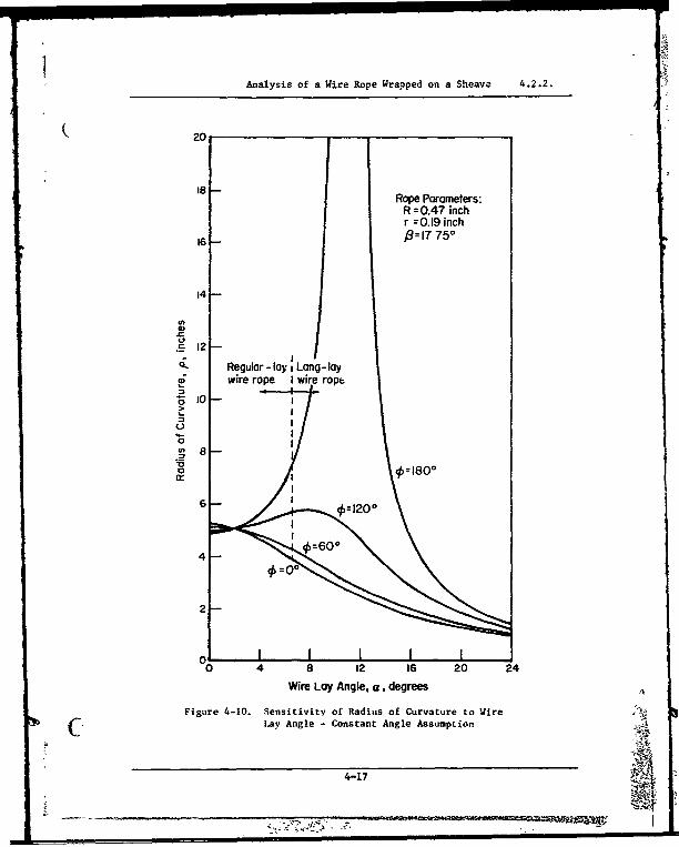
Analysis of a Wire Rope Wrapped on a Sheave 4.2.2.
20
Rope Parameters:R = 0.47 inchr =0.19 inch
16 1=,7 750
14-
. 12
cz Regular - lay 1 Lang -laywire rope I wire rop /
u4
8 -~ 10
0==00
0 4 8 12 16 20 24
Wire Lay Angle, a, degrees
Figure 4-10. Sensitivity of Radius of Curvature to WireC•'• Lay Angle - Constant Angle Assumption
4-17
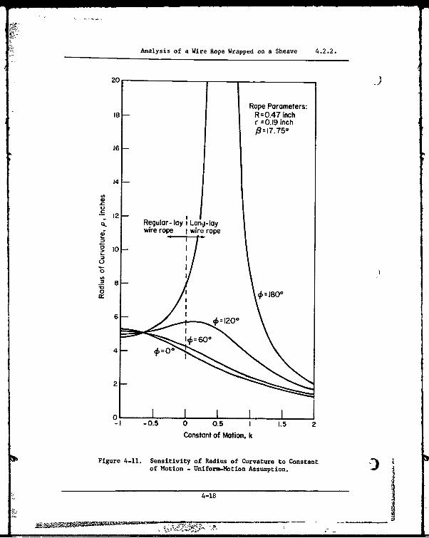
Analysis of a Wire Rope Wrapped on a Sheave 4.2.2.
20 _
Rope Parameters:18 R =0.47 inch
r =0.19 inch16-17.750
16
14
S12Regular- lay i Long-lay
4 wire rope I wire rope
I0 -
0
.2 8o = 180'
-4 - 0=50- 0.1.
Constant of Motion, k
Figure 4-11. Sensitivity of Radius of Curvature to Constantof Motion - Uniform-Motion Assumption.
4-18
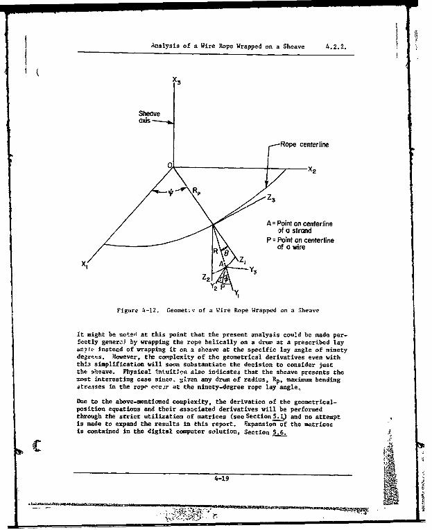
Analysis of a Wire Rope Wrapped on a Sheave 4.2.2.
t L
X3
Sheaveaxis
Rope centerline
A = Point on centerlineof a strand
P = Point on centerline,/ •R of a wire
X 1' -"--"AZ'Y3
Figure 4-12. Geometiv of a Wire Rope Wrapped on a Sheave
It might be noted, at this point that the present analysis could be made per-fectly generzi by wrapping the rope helically on a drum at a prescribed layatyle instead of wrapping it on a sheave at the specific lay angle of ninetydegref-s. sowever, the complexity of the geometrical derivatives even withthis simplification will soon substantiate the decision to consider justthe sheave. Physical int.uitken also indicates that the sheave presents themost interesting case since. giv•°en any drum of radius, Rp, maximum bendingstrasses in the rope occ-.r at the ninety-degree rope lay angle.
Due to the above-mentioned complexity, the derivation of the geometrical-position equations and their associated derivatives will be performedthrough the strict utilization of matrices (see Section5.1) and no attemptis made to expand the results in this report. Expansion of the matricesis contained in the digital computer solution, Section 5.6.
4-19AME
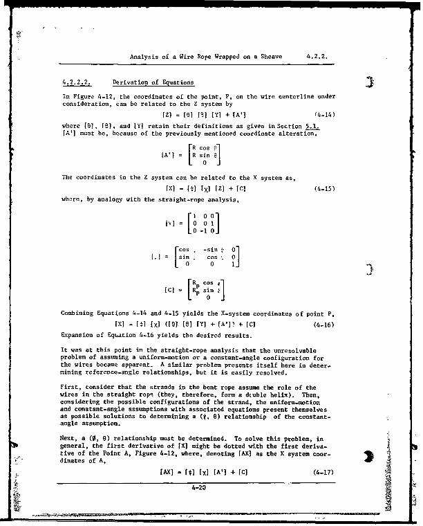
Analysis of a Wire Rope Wrapped on a Sheave 4.2.2.
4.2.2.2. Derivation of Equations
In Figure 4-12, the coordinates of the point, P, on the wire centerline underconsideration, can be related to the Z system by
[Z) = [61 [B] (Y) + [A'] (4-14)
where [0], [1], and IY] retain their definitions as given in Section 5.1.[A'] must be, because of the previously mentioned coordinate alteration,
FR cos-e[A'] R sin e
0
The coordinates in the Z system can be related to the X system as,
ix! = Mi [xl [Z) + [C] (4-15)where, by analogy with the straight-rope analysis,
[F1 00 10[vJ = 0ol
10 -1 0 i
rCS.-in 0]1.1 = sin cos
0 0 10
RCo oS
[C] R sin 10
Combining Equations 4-14 and 4-15 yields the X-system coordinates of point P,
[X] - [fl [XI ([81 [8] [Y] + [A']) + [C] (4-16)
Expansion of Equation 4-16 yields the desired results.
It was at this point in the straight-rope analysis that the unresolvableproblem of assuming a uniform-motion or a constant-angle configuration forthe wires became apparent. A similar problem presents itself here in deter-mining reference-angle relationships, but it is easily resolved.
First, consider that the strands in the bent rope assume the role of thewires in the straight rope (they, therefore, form a dcuble helix). Then,considering the possible configurations of the strand, the uniform-motionand constant-angle assumptions with associated equations present themselvesas possible solutions to determining a (t, 8) relationship of the constant-angle assumption.
Next, a (0, 8) relationship must be determined. To solve this problem, ingeneral, the first derivative of [X] might be dotted with the first deriva-tive of the Point A, Figure 4-12, where, denoting [AX] as the X system coor-dinates of A,
[AX] = [i] [X] [A'] + [C] (4-17)
4-20

T
Analysis of a Wire Rope Wrapped on a Sheave 4.2.2.
and, then, analogous to the straight rope analysis, the dot product is writ-ten,
[x'] - [AX'] s 1I'I iA'j cos a
where a retains its straight rope analysis definition of the lay angle ofthe wire in strand. This procedure could be used to determine the new con-stant (0, 8) relationship of the uniform-motion assumption or the varyingrelationship of the constant-angle assumption. Note that 8, the strand layangle, is not constant in the uniform-motion solution when taking deriva-tives, but is governed by the relation analogous to Equation 4-13
8 = tan-' R (4-18)Fp + cos 8
where Y is the relationship of t*, 8).
However, when this technique is employed, the resultant equations are verycomplex. The constant-angle solution for a new (0, 8) relationship appearsimpossible to solve in closed form. The uniform-motion solution must benumerically integrated for average a, and this is an equally forboding task.
Further, even if this analysis were successfully performed, it is doubtfulthat the resultant (t, 8) relationship would be correct owing to the assump-tions involved. The above analysis assumes a frictionless rope, i.e., allstrands and wires are free to move as warranted to retain a constant-angleor uniform-motion configuration. An actual rope, however, exerts frictionforces on the strands and wires which tend to maintain its configuration asthe rope is bent. In fact, over the entire length of the rope, the average(0, 8) relationship for the straight rope must remain true for the bentrope since, upon bending of the rope, the strands and wires do not shiftposition at the ends of the rope. Thus, the average relative wire-to-strand(0, 6) relationship holds.
Therefore, the analysis will proceed considering the uniform-motion assump-tion since if uniform motion does exist, then the relationship is alreadyknown. The difficulty oE assuming a constant angle is that the analysis be-comes very complex and thus, for simplicity, this assumption is abandoned.
One further point deserves mention in the determination of the (t, 6) and(0, 0) uniform-motion relationships. In discussing Figure 4-9 in thestraight rope analysis section of this report, the relationship of lay anglea to constant of motion K, it was noted that the curve was valid either forthe uniform-motion solution (constant K versus average a) in which a numer-ical integration was performed, or for the constant-angle solution (averageK versus constant a). Therefore, it is apparent that ct needn't be integratedto find the constant of motion, but the direct method of using average K fromthe constant angle solution can be utilized. This average K is simply one-half the reciprocal of the leading coefticient of Equation 4-10,
"K =I(a c- e - b' (4-19)
4-215
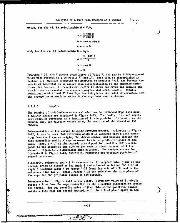
Analysis of a Wire Rope Wrapped on a Sheave 4.2.2.
where, for the (0, 0) relationship 0 = K8,
R tan c-r sin 0
b = tan a sin 8
c = cos 8
and, for the (t, 6) relationship 9 =K2,
Rp tanOa - R
b tan 8
c =0
Equation 4-16, the X system coordinates of Point P, can now be differentiatedtwice with respect to 4 to obtain X' and X". This task is accomplished in
Section 5.5. without expanding the matrices of Equation 4-16, not because the
matrix differentiation is easier than differentiation of the expanded equa-tions, but because the results are easier to check for error and because the
matrix results translate to computer-program statements simply. Finally,substitution of X' and X" into Equation 4-6 yields the radii of curvature forthe assumption of uniform motion in the rope bent over a sheave.
4.2.2.3. Results
The results of radii-of-curvature calculations for Standard Rope bent over
a 12-inch sheave are displayed in Figure 4-13. The family of curves repre-
sent radii of curvature as a function of 0, the position of the wire in the
strand, and, for discrete values of 6, the position of the strand on the
sheave.
Interpretation of the curves is quite straightforward. Referring to Figure
4-12, it can be seen that reference angle 6 is measured from a line emana-ting from the X system origin, the sheave center, and passing through the
rope centerline and is always measured in the perpendicular plane of the
rope. Thus, 6 = 0* is the outside strand position, and 6 = 1800 corres-
ponds to the strand on the side of the rope in direct contact with the
sheave. Figure 4-14 illustrates this relation. The various curves for
discrete 6 in Figure 4-13, therefore, represent the relative position of
strand to sheave.
Similarly, reference-angle 6 is measured in the perpendicular plane of the
strand, which is tilted at lay angle B and oriented such that the line at
angle 6 locating Point A in Figure 4-12 forms its axi. of tilt and is the
reference line for 0. Hence, Figure 4-14 can only show the true plane of
the rope and the projected planes of the strands.
Interpretation of Figure 4-13 is now clear. Given any value of 0, simply
rotate a line from the rope centerliv'. in the clockwise direction to locate
the strand. For any specific value of 0 at this strand position, simply
rotate a line from the strand ceanterline in the tilted plane again in the
4-22
Z'~v~S~'!
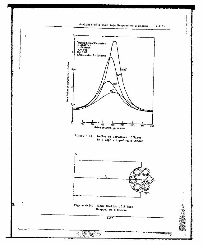
Analysis of a Wire Rope Wrapped on a Sheave 4.2.2.
'Standard Rope" ParametersR=047inchr=0 19OichK,1 448
SheOve rOdius, R z 12 inches
.4
2
0 45 90 135 '80 225 20 315 360Reference Angle, 4,, degrees
Figure 4-13. Radius Of Curvature of Wiresin a Rope Wrapped on a Sheave
X3
Figure 4-14. Plane Section of A RopeWrapped on a Sheave
4-2
-I
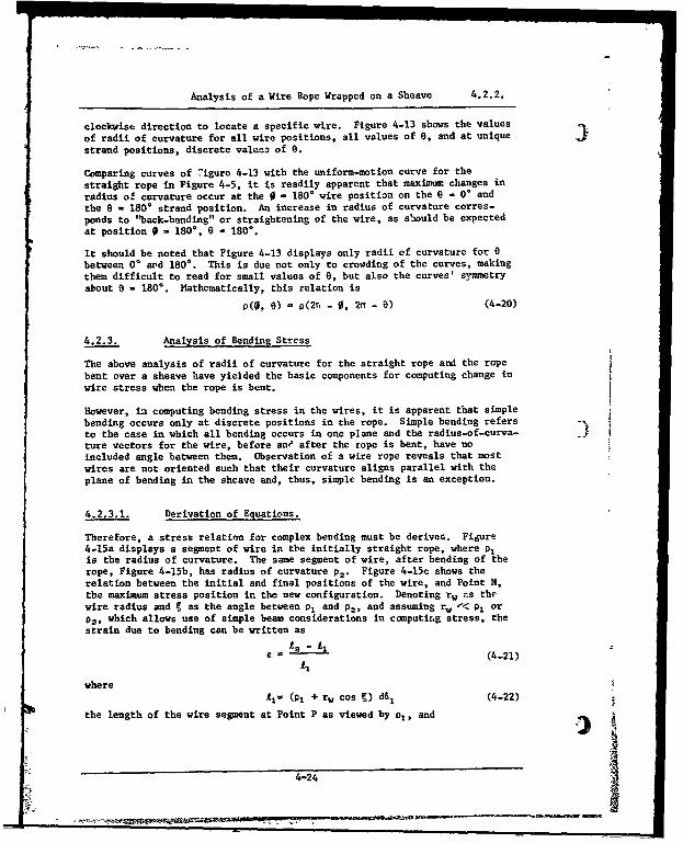
Analysis of a Wire Rope Wrapped on a Sheave 4.2.2.
clockwise direction to locate a specific wire. Figure 4-13 shows the values
of radii of curvature for all wire positions, all values of 0, and at unique
strand positions, discrete value3 of e.
Comparing curves of -igure 4-13 with the uniform-motion curve for the
straight rope in Figure 4-5, it is readily apparent that maximum changes in
radius of curvature occur at the 0 = 180* wire position on the 0 = 0* and
the 0 = 180* strand position. An increase in radius of curvature corres-ponds to "back-bending" or straightening of the wire, as should be expectedat position 0 = 180%, 8 = 180%.
It should be noted that Figure 4-13 displays only radii cf curvature for 0between 0' ard 1800. This is due not only to crowding of the curves, makingthem difficult to read for small values of 8, but also the curves' symmetryabout 0 = 180%. Mathematically, this relation is
p(0, 0) = p(2r, - 0, 2n - 0) (4-20)
4.2.3. Analysis of Bending Stress
The above analysis of radii of curvature for the straight rope and the ropebent over a sheave have yielded the basic components for computing change inwire stress when the rope is bent.
However, in computing bending stress in the wires, it is apparent that simplebending occurs only at discrete positions in the rope. Simple bending refersto the case in which all bending occurs in one plane and the radius-of-curva- 3ture vectors for the wire, before ane after the rope is bent, have noincluded angle between them. Observation of a wire rope reveals that mostwires are not oriented such that their curvature aligns parallel with theplane of bending in the shcave and, thus, simple bending is an exception.
4.2.3.1. Derivation of Equations.
Therefore, a stress relation for complex beuding must be derived. Figure4-15a displays a segment of wire in tbe initially straight rope, where p,is the radius of curvature. The same segment of wire, after bending of therope, Figure 4-15b, has radius of curvature p.. Figure 4-15c shows therelation between the initial and final positions of the wire, and Point N,the maximum stress position in the new configuration. Denoting rw -s thewire radius and § as the angle between P1 and p,, and assuming rw -< p1 orp., which allows use of simple beam considerations in computit.g stress, thestrain due to bending can be written as
£ = •(4-21)
whereA1- (01 + rw cos g) d61 (4-22)
the length of the wire segment at Point P as viewed by p1 , and
4-24
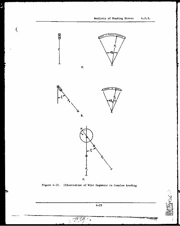
Analysis of Bending Stress 4.2.3.
a.
2
b.
P2
IC.
Figure 4-15. Illustration of Wire Segments in Complex Bending
4-25
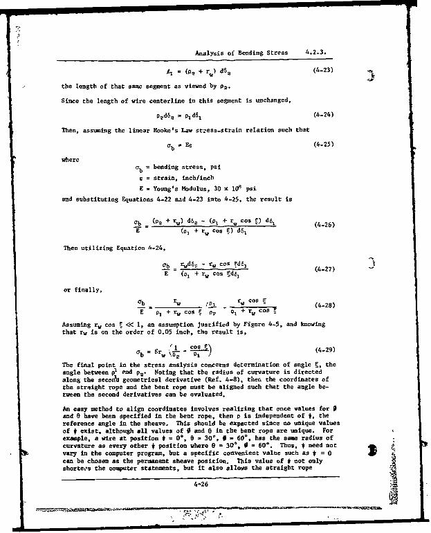
Analysis of Bending Stress 4.2.3.
'2 (P2 + r) d62 (4-23)
the length of that same segment as viewed by P2.
Since the length of wire centerline in this segment is unchanged,
•d52 - p2d5 1 (4-24)
Then, assuming the linear Hooke's Law st-ess-strain relation such that
a b - Ee (4-25)
whereab = bending stress, psi
e = strain, inch/inch
E = Young's Modulus, 30 x 10' psi
and substituting Equations 4-22 sad 4-23 into 4-25, the result is
-b = (02 + rw) d62 - (p, + r, cos ý) d6I (4-26)E (o1 +rw cos g) d6l
Then utilizing Equation 4-24,
b rwd6, - rw cos Fd61 (S(4-27)E (01 + rw cos ýd8,
or finally,
ob rw I w cos C (4-28)
E p, + rw cos o2 o1 + rw Cos
Assuming rw cos .<< 1, an assumption justified by Figure 4-5, and knowingthat rw is on the order of 0.05 inch, the result is,
'r 1 cos_§ (4-29)
The final point in the stress analysis concerns determination of angle t, theangle between po and P2. Noting that the radius of curvature is directedalong the second geometrical derivative (Ref. 4-8), then the coordinates ofthe straight rope and the bent rope must be aligned such that the angle be-tween the second derivatives can be evaluated.
An easy method to align coordinates involves realizing that once values forand e have been specified in the bent rope, then p is independent of #, thereference angle in the sheave. This should be expected since no unique valuesof * exist, although all values of 0 and 0 in the bent rope are unique. Forexample, a wire at position $ = 0, 0 - 30, 0 - 60%. has the same radius ofcurvature as every other * position where 0 = 30%, 0 = 60%. Thus, # need not 4
vary in the computer program, but a soecific convenient value such as # = 0)can be chosen as the permanent sheave position. This value of # not onlyshortees the computer statements, but it also allows the straight rope
4-26
* '.4V
Analysis of Bending Stress 4.2.3.
coordinate system to be placed at (Rp, 0, 0) such that the straight ropeis always tangential to the bent rope, Figure 4-16.
The coordinates are now aligned such that the Z coordinates of the straight
rope correspond to the X coordinates of the bent rope as
71s= Yn1 I
Zs" = xn" (4-30)
z3 " f=t 2"
where Xm, Xns, Xn are the new X coordinates of the straight rope. Now as0 and e are varied, the point whose radius of curvature is being consideredis essentially always located in the X, - X, plane. Therefore, points in theX- - X3 plane located by the same values of 0 and 0 are identical points.Dotting X" and Ln", the cosine of • can be found as
i,, . -
cos u n (4-31)
0x
C3
0Rope centerline
Z 1 Z
Figure 4-16. Coordinate Alignment Used for ComparingRadii-of-Curvature Results
4-27
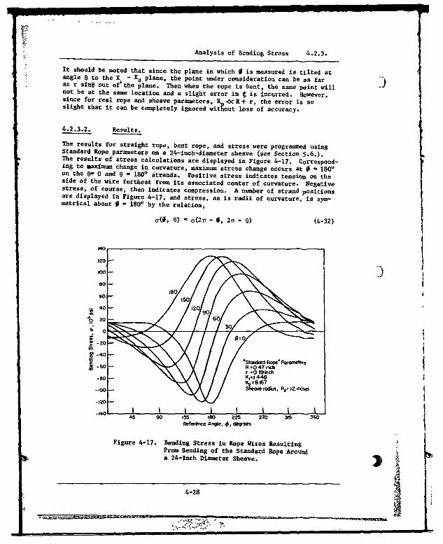
Analysis of Bending Stress 4.2.3.
It should be noted that since the plane in which 0 is measured is tilted atangle B to the X - X, plane, the point under consideration can be as faras r s-np out of the plane. Then when the rope is bent, the same point willnot be at the same location and a slight error in C is incurred. However,since for real rope and sheave parameters, R, <<R+ r, the error is soslight that it can be completely ignored without loss of accuracy.
4.2.3.2. Results.
The results for straight rope, bent rope, and stress were programmed usingStandard Rope parameters on a 24-inch-diameter sheave (see Section 5.6.).The results of stress calculations are displayed in Figure 4-17. Correspond-ing to maximum change in curvature, maximum stress change occurs at 0 - 1800on the e= 0 and 0 = 1800 strands. Positive stress indicates tension on theside of the wire furthest from its associated center of curvature. Negativestress, of course, then indicates compression. A number of strand positionsare displayed in Figure 4-17, and stress, as is radii of curvature, is sym-metrical about 0 = 1800 by the relation,
a(0, 6) - c(2- - 0, 2n - 6) (4-32)
120
I O I I
100
s o
40 -3 1
60 -
15
2 0 -6
-20
Lo -40 I I,
Reference Angle, 4,. degrees
Figure 4-17. Bending Stress in Rope Wires ResultingFrom Bending of the Standard Rope Around ltr
0a 24-nch Diameter Sheave. ) R
r 44-28
From Bending of the Su andard Rope Arounto
Analysis of Bending Stress 4.2.3.
Although the magnitude of the stress at 0 - 180%, - 180° is slightlygreater than that at 0 = 180%, - 0 this should not be construed as a gene-ral result. The important consideration, though, is that maxima alwaysoccur at these two positions and at these points § = 0. Therefore, substi-tution of 0 = 180* at 6 = 0* and 6 = 180* into the radius of curvature equa-
4 tions greatly simplifies them for future work which will include evaluationof the influence of various rope and sheave parameters on rope-wire bendingstress.
4.3. CONTACT STRESSES
Contact stresses in a wire rope are one of the most important determinantsof its fatigue life and are, by far, the most difficult to analyze. Todate, no reliable and accurate analysis has been completed, primarily be-cause these stresses, even under low rope tensile loads, are so high thatthe wires yield, changing the geometry and thus invalidating the elasticforce-geometry-stress relationships normally used for stress computation.
There are four areas in a normal wire rope where contact stresses can beinduced:
1. At the wire-sheave interfaces
2. At the interfaces between wires in a strand
3. At the interfaces between wires in adjacent strands4. At the interfaces between the wires in the strands and the wires
in the core of an IWRC rope.
4.3.1. Wire.Sheave Interface
No published analysis is known for the contact stresses induced at the wire-sheave interface. This represents a major gap in wire-rope analysis since,for many common rope systems, this is the area where wire failures firststart.
One investigator (Ref. 4-9) has published a derivation of the standard for-mula for the average contact pressure. It is written as follows:
2 T (4-33)
where
p = average contact pressure, lb/in2
T = tensile force on rove, lb
D - sheave diameter, in
d = rope diameter, in.
This derivation is based on a static analysis only, and the investigator goeson to derive equations for the average pressure that include the effects ofrope weight, friction, differential sheave-rope rotational velocity, and a
4-29
-YzPk_
Wire-Sheave Interface 4.3.1.
differential tension in the rope between first and last rope-sheave contact.The resulting equations are quite complex, and, except for unusual conditionS, 9the average pressure changes only slightly.
No analytical work on actual wire-sheave contact pressures is known. Oneinvestigation (Ref. 4-10) did experimentally determine the "footprint" of awire rope wrapped around a sheave-like radius for the quite unusual condi-tion of an aircraft arresting-gear cable wrapped around an arresting hookpoint.
4.3.2. Wire Interfaces in a Strand
The radial force on an infinitely thin wire helically wrapped on a cylinderis (Ref. 4-11)
F = T sin2
2 (4-34)w V pwhere
F = force between wire and cylinder (core wires), lb
S= lay angle of wire in strand, measured between strandand wire, degrees
Tw = tensile force on wire, lb
= f radius of curvature of wire, in
The individual radial forces must then be combined to relate to the strandtension, Ts. For a simple seven-wire strand with wires of equal diameter,the relation is (Refs. 4-7 and 4-12)
T cos 2 a sin
2 a
Ff= d (1+6cos• (4-35)w d (+ 6cos5
a)w
where, in addition to the terms above:d = diameter of wire, inw
No published relation for more complex strands is known, although its formu-lation would be a relatively simple extension of the work described above.
The contact stresses between the parallel wires are (Ref. 4-13)
i' - • • [ I 1 + Z• 2 ] k " .
g - 1 k(4-36)
o, [ 1+ }b] b (4-37)
4-30
Wire Interfaces in a Strand 4.3.2.
b
0 z 2]I (4-38)
where b is the half-width of the rectangular area ot contact between thewires and is given by
b A (4-39)
For parallel wires,d (1 - ii)
A = (4-40)
In these equations
E = modulus of elasticity, lb/in2
S= Poisson's ratio
ax - stress in axial direction, lb/in2
cy - stress in direction tangential to the wire, lb/in2
and az - stress in direction radial to the wire, lb/in2
In more complex strand configurations, parallel wire contact is not achieved.(See Volume I of this Wire-Rope Handbook for a discussion of strand construc-tions.) When this is the case, the simplified equations presented abovecannot be used, and the more complex methods discussed in the next sectionmust be applied.
4.3.3. Interstrand Wire Contact
In general, the contact forces and stresses induced between the wires ofadjoining strands must be computed using the geometry of the particularrope under consideration and the general contact-stress formulas, which arefar too complex for the scope of this handbook. Once the forces are known,the stresses can be computed using the methods presented in Reference 4-13.Several general comments on the problem and several solutions for specificrope geometries are, however, in order.
In computing the interstrand contact force, it is necessary to know (orassume) the amount of support contributed by the core, since this governsthe interstrand spacing and, thus, the force. Most investigations, whenanalyzing synthetic-core ropes, assume a worst-case condition--no coresupport at all. This, of course, produces the highest interstrand forces.It ia, however, not a particularly realistic assumption, especially when arope is new and subjected to only moderate forces. The actual interstrandforce is an extremely complex function involving core material, core hard-ness, core condition, core size, length and type of rope service, and manyother variables. In view of this, the assumption of no core support seemsthe only one practical for general rope analysis. (Of course, for specificsituations the amunt of core support can be determined, at least roughly,by measurements.)
4-31
Interstrand Wire Contact 4.3.3.
Another fact which makes the calculation of interstrand contact stressesunrealistic is that they are so high, even for relatively low rope tensileloads, that the yield strength of the material is exceeded. All of theequations are based on elastic behavior. No complete analysis attemptingto account for the actual plastic behavior is known. (One incompleteattempt is discussed later.)
Even with these drawbacks, evaluation of the stresses is of value becausethey can be used to qualitatively evaluate various constructions.
4.3.4. Interstrand Contact Forces
For any six-strand rope, the maximum interstrand contact force per unit ofrope length is (Ref. 3-3)
Fs sin 0 tan 0 (4-41)a 6R
where F = interstrind contact force, lb5
T = tensile force on rope, lb
R = pitch radius of strand, measured from ropecenterline, in
= lay angle of strand in rope, measured betweenrope and strand centerlines, degrees.
This interstrand force is actually imposed at discrete points along thelength of the strand where the outer wires touch. The distance betweenthese contact points is 2nr
c n tan (4-42)
whereLc = distance between interstrand contact points, in
ro . pitch radius of outer wires measured from strandcenterline to wire centerline, in
no = number of outer wires in a strand,
t 0 = lay angle of outer wires, degrees.
Combining equations 4-41 and 4-42 gives the interstrand force at each con-tact point:
f2nT sin 8 tan B) (;R'~T(.4Fs \ 6n tan' r T (4-43r0 0 0
For a 1-3/8-inch-diameter, 6 x 25, filler-wire, Lang-lay, round-strand wirerope (exact dimensions given in Reference 3-3), the interstrand force is
F = .0123T (4-4!.)
4-3z
Interstrand Contact Stresses 4.3.5.
4.3.5. Interstrand Contact Stresses(l
As noted above, the equations defining all of the interstrand contactstresses are extremely complex, involving the evaluation of several ellip-tic integrals, (They must, however, be used if a solution to the combined
stress problem is attempted.) It is possible and fairly simple to computethe maximum interstrand contact stresses. They can be found by solving thefollowing simplified equations (Ref. 4-13):
BA=I I+ I+ I LI-I)oe (4-45)
B ý1 - + +" 1 1 + 1)os Oc (4-46)2 w 1 rw
A + B Eu(4-47)
where
-e - wire crossing angle, degrees.c
Then, using charts from Reference 4-13 to find the values of the terms Cb,
Ca, CT, CG, and CZS from the value of B/A, the stresses can be found asfollows:
b - Cb(Fc.) 1 /3 (4-48)
=Co (4-49)
A . (.) (4-501max k
G•mx = CG A/ (4-51)
ZS = CZS b (4-52)
whereb - semininor axis of ellipse of contact, in
o . maximum normal stress, lb/in3
T - maximum shear stress, lb/in2max
TGmax -. maximum octahedral shear stress, lb/in2
Z S- distance below wire surface at which Tmax
and -Gax occur, in.
The maximum compressive contact stress always occurs at the surface in the
z direction.
Using the same 6 x 25 rope referenced above, and utilizing the approximate
radius of curvature of the outer wires discussed in the section on bending
stress (p - rw/sin2 c, which introduces only a negligible error), the maxi-
mum contact stresses computed using the formulas above are
4-31

Interstrand Contact Stresses 4.3.5.
reax - - (5.51 x le0) TRI13
T max= (1.76 x le) TRI/3
TGmax (1.58 x leO) TR1/3
To illustrate the magnitude of these stresses, only 183 pounds of rope ten-sion would induce a maximum shear stress of 100,000 psi, which is about theyield point of some rope wire. The tension in the rope is higher than thiswhen it is being manufactured. Thus, any meaningful stress analysis of evena straight rope must account for core support and plastic behavior of thewires,
4.3.6. Core-Strand Interface Stresses
No analysis of the contact stresses at the core-strand interface in an IWRCrope is known. The stresses here, however, are probably even higher thanthose between the strands because the wires in the core rope are generallysmall. Some confirmation of this assumption has been found when IWRC ropesthat have been cycled in the laboratory for only a small percentage of theirfatigue life are dissected. Frequently, the core wires are found in smallpieces.
4.3.7. Elastic-Plastic Analysis
Obviously, the absurdly high values of contact stress that are predicted forlow rope loads, assuming elastic behavior of the wire, make any such numeri-cal results useless except as a starting point for an elastic-plasticanalysis. One investigator (Refs, 4-14 and 4-15) attempted such an analysisbut did not complete it.
4.4. TORSIONAL AND SHEAR STRESSES
No published analysis of torsional stresses in a wire rope is known. Oneinvestigator (Refs, 4-16 and 4-17) has derived equations for torsionalstresses in strands but has not extended these to rope.
The importance of directly induced shear stresses, either torsional or longi-tudinal, is questionable when the rope ends do not rotate (ends fixed ortorque-balanced) thus preventing significant rotational strain. As pointedout in the section on Failure Modes in Wire Rope, one chiracteristic wirefailure mode is a typical 45-degree shear-type failure, but this type can be(and probably is) induced by the complex combination of tension, bending,and compressive contact stresses at the point of wire failure.
4.5. WIRE ROPE DYNAMICS
In almost all wire-rope systems, the rope is subjected to dynamic loads to agreater or smaller degree. In most of these cases, these dynamic loads are
4-34
I.
Wire Rope Dynamics 4.5.
either small enough to be ignored or can be accounted for by simply addingthe forces due to acceleration to the design loads. The dynamic action ofthe rope itself is nor considered.
However, in some systems, the dynamic effects of the rope are of such impor-tance that they must be considered. Examples are mooring systems, tow ropes(and cables) in both water and air, and aircraft arresting-gear systems.Many groups have studied and solved these problems, at least to a degreesufficient for engineering accuracy. These solutions are typically quitecomplex and require a computer for their use. A complete coverage of thissubject is beyond the scope of this handbook. Each subject is coveredbriefly, and the interested reader is provided with reference for more com-plete discussion and mathematical detail.
Generally, a survey of the literature available indicates that there is adistinct lack of published experimental and field data by which the analyti-cal approaches can be validated. Field data are particularly lacking in theopen literature. This is clearly an area in which more work is needed. Oneexception is a report (Ref. 4-18) on a series of experimental ocean liftsduring which records were made of dynamic loads and frequencies.
4.5.1. Longitudinal Forces
Various techniques for computing dynamic longitudinal loads are surveyed inReferences 4-19, 4-20, 4-21, and 4-22. Of these, Reference 4-20 is parti-cularly useful since it incorporates the information contained in the othersurveys and also indicates if there was any experimental verification of theanalysis. This report also lists a large number of references, both reportsand articles, on this subject.
Snap loading, when the cable tension goes to zero then snaps to high value,is a special and very damaging case of dynamic longitudinal loading. It isexamined both analytically and experimentally in Reference 4-13 for both awire rope and a wire rope with a short length of nylon rope attached. Asmight be expected, the nylon had a substantial mitigating effect on thepeak loads. Another group analyzed the problem using an analog computer(Ref. 4-24). Also, more recently, a series of experiments (Ref. 3-30) wasconducted where the rope--in this case a strand--load was varied from avery low value (50 pounds) to from 25 to 50 percent of its breaking strength.The cycling rate was 3 and 6 seconds per cycle, something less than trueimpact, but not unreasonable for the loading rate that might be expected ina long wire rope. The results are shown in Table 4-2. Especially at thehigher maximum load conditions, the lifetimes are quite short.
A computer program to solve transient, dynamic, and snap-load responses tosurface excitations is presented in Reference 4-25. It was published subse-quent to Reference 4-20, and has not been validated experimentally.
4-352
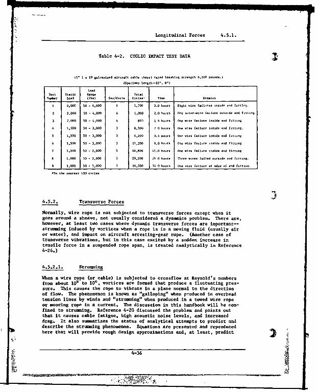
Longitudinal Forces 4.5.1.
Table 4-2. CYCLIC IMPACT TEST DATA
W' I x 19 galvanized aircraft cable ibare) rated breaking strength 8.200 pounds.)
(Specimen Length--12'. 80)
LoadTest Static t.ng. Total
number Load (ibs) Sec/Cycle CyclesW Time Reamras
1 2.00C 50 - 4,000 6 1.700 3.0 hour. Eight wire falures tinside end fittlg.
2 2.000 50 - 4,000 6 1.000 2.0 hours Ore outer- re failure outside end fitting
3 2.000 50 - 4,000 6 800 1 6 hours One wire failure inside end fitting
4 1.500 50 - 3.000 3 0,300 7 0 hours fne utre failure inside ed fitting.
5 1,500 50 - 3,000 3 4.200 3.5 nocrs On itre failure inside end fitting
6 1.500 50 - 3,000 3 11.200 9.0 hout. (lie wire failure inside end fitting
7 1,00 50 - 2.000 3 48,800 41.0 honrs One wire failure inside end fitting
0 1.000 30 - 2,000 3 29.200 25 0 hours Three wires failed outside end fitting.
9 1,000 50 - ?,000 3 16.300 114 0 hours One wire failure at edge of end fitting.
*To the nearest 100 cycles
4.5.2. Transverse Forces
Normally, wire rope is not subjected to transverse forces except when itgoes around a sheave, not usually considered a dynamics problem. There are,however, at least two cases where dynamic transverse forces are important--strumming induced by vortices when a rope is in a moving fluid (usually airor water), and impact on aircraft arresting-gear rope. (Another case oftransverse vibrations, but in this case excited by a sudden increase intensile force in a suspended rope span, is treated Enalytically in Reference4-26.)
4.5.2.1. Strumming
When a wire rope (or cable) is subjected to crossflow at Reynold's numbersfrom about 106 to 106, vortices are formed that produce a fluctuating pres-sure. This causes the rope to vibrate in a plane normal to the directionof flow. The phenomenon is known as "galloping" when produced in overheadtension lines by winds and "strumming" when produced in a towed wire ropeor mooring ropp in a current. The discussion in this handbook will he con-fined to strumming. Reference 4-20 discussed the problem and points outthat it causes cable fatigue, high acoustic noise levels, and increaseddrag. It also sumiarizes the status of analytical attempts to predict anddescribe the strumming phenomenon. Equations are presented and reproducedhere that will provide rough design approximations and, at least, predict
4-36
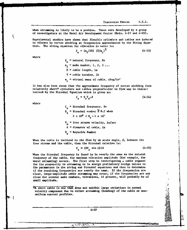
Transverse Forces 4.5.2.
when strumming is likely to be a problem. These were developed by a groupof investigators at the Naval Air Development Center (Refs. 4-27 and 4-28).
Experimental studies have shown that flexible cylinders and cables are inducedto vibrate by vortex shedding at frequencies approximated by the String Equa-tion. The string equation for vibration in water is:
f n = (n f/2H) (T/m c) (4-53)
where
fn - natural frequency, Hz
nf . mode number, 1, 2, 3 ...
H = cable length, in
T = cable tension, lb
m = virtual mass of cable, slug/in'
It has also been shown that the approximate frequency of vortex shedding fromrelatively short* cylinders and cables perpendicular to flow may be charac-terized by the Strouhal Equation which is given as:
fs = SsVo/d (4-54)
wheref = Strouhal frequency, Hz
S = Strouhal number ý 0.2 when5
2 x 10² <R r <1 x 0
V = free stream velocity, in/sec0
d = diameter of cable, in
R rf= Reynolds Number- r
When the cable is inclined to the flow by an acute angle, 0, between thefree stream and the cable, then the Strouhal relation is:
f . (SVo sin 0)/d (4-55)
When the Strouhal frequency is found to be nearly the same as the naturalfrequency of the cable, the maximum vibration amplitude (for example, theworst strumming) occurs. The first step in investigating . cable segmentfor its propensity to strumming is to assign preliminary design values tothe parameters in the string and Strouhal equations and then to determineif the resulting frequencies are nearly the same. If the frequencies areclose, large-amplitude cable strumming may occur; if the frequencies are notclose for several mode numbers, vibrations, if present, will probably be ofsmall amplitude.
*A short cable is one that does not exhibit large variations in normalvelocity component due to either streaming (bending) of the cable or non-uniform current profiles.
4-37

Transverse Forces 4.5.2.
4.5.2.1.1. Increased Drag Due to Strumming
The following equation has been developed to predict the maximum drag coeffi-cient (values for CD when fs a in) that can be expected in short sections ofa strumming, smooth, circular cable,
C D = CD (1 + lO(d-/mc)21 (4-56)f s
SwhereCD = drag coefficient for strumming cable
S
CD = drag coefficient for stationary cable
d = cable diameter, in
mc = virtual mass of cable, slug/in.
Equation 4-56 has been verified for small-diameter (0.057 in < d < 0.140 in)smooth cables of mass per unit length from 1.16 x 10-` to 9.3 x 10` slug/ftover a range of Reynolds numbers from 300 to 1,300. No verification of theequation has been made for stranded cables.
4.5.2.1.2. Strumming Suppression.
If strumming must be reduced or eliminated in a cable, changes can be made tothe cable system so that the natural frequency and Strouhal frequency aremuch different or a cable fairing can be added to disrupt the vortex-sheddingprocess. Figure 4-18 (Ref. 4-27) shows how four cable fairings compare interms of strumming drag coefficient and strumming force over a range ofReynolds numbers. In Table 4-3 (Ref. 4-20), several additional fairings aredescribed and performance characteristics listed. It should be noted thatfor some fairings the drag coefficient is increased over that of a bare cableeven though strumming force or vibration amplitude is reduced.
To summarize, analysis and design procedures to predict, describe, and supp-ress strumming in long cables under oceanic conditions are not possible.Today's procedures consist of comparing the natural frequency of a cable(Equation 4-53) with the Strouhal frequency for the cable in flow (Equa-tions 4-54 and 4-55) to determine if strumming is likely. If strumming ispredicted on this basis, changes are made to the system or some fairing isadded to the cable.
4.5.2.3. Aircraft Arresting-Gear Cable.
The dynamic effects in aircraft arresting-gear cable used on carriers areprobably the most violent of those normally induced in any coimon wire-ropesystem. An extensive body of literature exists on the subject covering bothanalytical and experimental work, but a full discussion of this extremelycomplex area is clearly beyond the scope of the handbook because of itsspecialized nature.
4-38

Transverse Factors 4.5.2.
2.0- f L IHaired 1.8dstreamer 7-1.97
1.8 - -1.7•• eeec
1.6-
1.5-
C.) 1.4 Reference
__ (s )oth round cable). 1.3
0C.. 1.21
S --Twisted paira _ .1 - (pitch= 15d)
E 1.0 -f7E 20d
C" AntinodeS0.9 splitter
0.8-
0.7-
0.6
0.5
0.4 - E '-
.3I I I I500 700 900 1100 1300 1500
Reynold's NumberFigure 4-18. Strumning Drag Characteristics
4-39 =
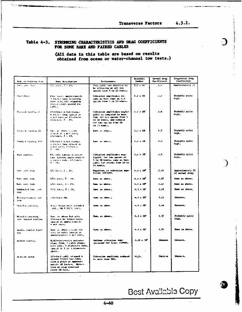
Transverse Factors 4.5.2.
Table 4-3. S7thIIHIG CEARACTURISTICS AND DRG COEFFICIETSFOIL SOME BARE AND FAIME CABLE
(All data in this table are based on resultsobtained from ocean or water-channel tow tests.)
R. bYale . YormakL 0mg Tangeantial D~rag
-6-P, .or Jjtrau. ('N. dop.- IS-.rptlon Performancea %-her Co..tfIcifont Coefficient
~~~~~~r~~1L .. flr "~. ha.. *1.a..a a. ob...r-. to. I., .lu 1.4 ApproxilAdt~ty 2.1he wilirat nLe at all tawsptad. gr... S to 15 knot..
SJ~rml... Pl.*.....paaa. V.1b.Mi.. axxpLft~d.. tn. 1.1 . to 2 Probably quitel 00 onv.. ?.uitftgt ame & bar., rae. at tgo high.
;r,. li-.iJ mppn .~ . trom I to 15 knot...*I>ý..J .1.1 a..It upndst.
r* al.I.
tl.... .1 Ijar!.. I tiju.Lntj, 0,.I~n aiwosm~. %ibm.stionaa ipl~tuad., ineall- 1.-, 107 J.6 Probably quiteaIn.-.lefton P..paJ Al 1,ibL a* *om..rvel to bare high.P.r in.I, .oo ih-i.u-". V..,. focam .. Ileedad frem I
.I,....r. I .IV. to 10 koet. amd rwdinc.-dScar tow P.p.ds gem, 10to _,I knot..
Id .mc It ~ o .o.. .. Pt Saom A. .bu%... 1.2 .0 . Probably quite
.,.J Al ... ar.. . high.
I,,~~~~~n.Jjo c4cc, I ~ .. n~,.lo... ,.. L.a.,. .2 to1 I.E Probably quit#* a.-,.* I.... .~... athigh.
h..bIJII..,Wl.bl.ampsa. as, - Vibraiaaon &Vplttwde. owt- 1.'I a LW 9.5 Probably quite
.,.. arin.i .wpr-its[- I. kigibl. fer too. ap... of high.1.... ". -. LI.n., to I0 knot.i. *mo as bar.7 IV. .4014 t~ar Ire-d tro 1toI
I$ knot..
or~~ 1c.Va. 2 .,r*I .La fagait.. cat vibration am- %.j X 10' 1.331 Appmox.imately 2%.lttcal. -maknoawo. of normal drag.
Sir. sr. rop. ~ .L a,7 IV. Sam. a. .0ev.. O. . lo 10 .37 lsai. a. above.
1114r. .&v.to. .23. 111 .. 1.. %am. a. aovea. 6.i a top 3.22 Saw a. above.
CO.MPj,.tJ I-If. Ifr. lot IJ Ir... 7 V1'. sof s. jaboat. 6c.) % 10 .45 Some a. above.m..p.
1IctA. .. aa.J -Ir- (10-c.. O. am..f a. abs... *. .. Mr 1.221 Unknown.r..P.
nri*. .j .. a. il,. o.,..,. braii ovc r .,r.nd.J Na a. 40e. s. *1 1.416 Unknown.4hi. Of .) I Il/$:r~'
£rJL.aJ. it-.rn .ms .* ad..iot Wtt. Sm.. so above. 6.)1 a to' 1.3? Probably quite,it, l.cim.A aIiria. Il.Lo.. hav I-Lead hair, high.
. ~ n.h.s,
J-~bk, 2Li.Ja~r -- AD- . -IFv... pt- Sim. " aboww. 6.1 a 1W' .~796 Same a above.an,...., .cr pa.St
Itshb.-. 116...0Ol-r-tih poalu.- ottfmpi uibratie.as p *o-.23 a t'.ew Unknown ntois.th... film. 2 31-l6 disoo- pro..1on, tfo L,.s0 ribbon.c~r-. ,aid. %, dI*.c.ra longt.
apart. at I aoS.i~~r
fkL41~j .tr~k hj-c-mfd h jhl. orapped a Vibration, M Pitt". mrdm.d My.S.. Cnkote-0 Utbnoen..crna~a -n.! I.Lnh o c.hle al, mor. than 507..nubk a pitch al approat-matpl' t0 Lnch.... Nm.--tion. of wriap rvver.,d
.,~my10 fe".-
Bcst Avao:Lb13 copy4-40 ý
Transverse Factors 4.5.2.
The most extensive and thorough analysis of the problem is contained in aseries of reports and articles by Ringleb (Refs. 4-25, 4-27, and 4-30).Though no details of the tests are given, it is stated that the analysishas been confirmed by experiments. Other references on the subject includeReferences 4-2, 4-10, 4-31, and 4-32. For further and more up-to-dateinformation, the serious investigator should contact the Naval Air Engin-eering Center directly.
4i I
-4 4
-- w~wke oft -zagsN PW
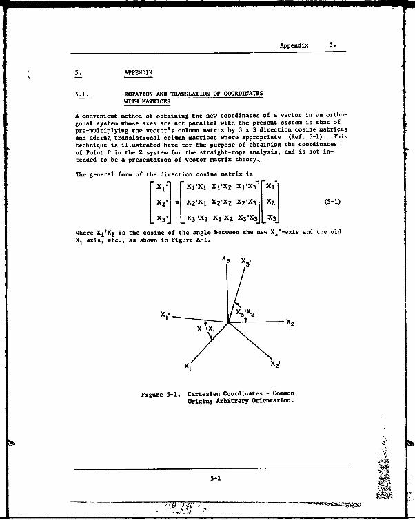
Appendix 5.
- 5. APPENDIX
5.1. ROTATION AND TRANSLATION OF COORDINATESWITH MATRICES
A convenient method of obtaining the new coordinates of a vector in an ortho-gonal system whose axes are not parallel with the present system is that ofpre-multiplying the vector's column matrix by 3 x 3 direction cosine matricesand adding translational column matrices where appropriate (Ref. 5-1). Thistechnique is illustrated here for the purpose of obtaining the coordinatesof Point P in the Z system for the straight-rope analysis, and is not in-tended to be a presentation of vector matrix theory,
The general form of the direction cosine matrix is[X1i X1 'XI Xl'X2 XI'X3 1EIS= X2 'XI XXZ XZ'X 3 (5-I)
X3' X3 'Xl X'xz xs'x3JL xsJ
where Xl'XI is the cosine of the angle between the new Xl'-axis and the oldX1 axis, etc., as shown in Figure A-1.
X3 X31
X1. V IX2 X
Xt X 2'
XI1X
Figure 5-1. Cartesian Coordinates - CommonOrigin; Arbitrary Orientation.
5-1

Rotation and Translation of Coordinates With Matrices 5.1.
crs 01[Y] = sin 0 (5-2)
Before any translation from the Y to the Z system can occur, the respectiveaxes of the two systems must be parallel, which can be accomplished by tworotations of the Y system. The first rotation is through angle 8 about theY1 axis, resulting in the rotation matrix
[1 0 0 1[81 = 0 cos 8 sin B (5-3)
[O-sin 3 cos 9 1
Another rotation through angle 6 about the new Y3 axis formed by the 8 rota-tion gives
[cos e -sin e0[ s] = sinG cos e (5-4)
[0s 0 1]Point P, now in a syste parallel with the Z system, can be translatedthrough the coordinates of Point A to give
[Z] = [e] [8] [Y] + [A] (5-5)
where
[A = R sin 0 (5-6)
[R 6 cot 9
Expansion of Equation 5-5 produces the Z coordinates of P
((R + r cos 0) cos 0 - r sin 0 cos $ sin 6)[Z] = (R + r cos •)sin 6+ r sin 0 cos 6 cos 0)] (5-7)
[(1R e cot S - r sin 0 sin 8)
5.2. DERIVATION OF REFERENCE ANGLE RELATIONSHIPIN STRAIGHT ROPE
The choice of coordinates for the straight-rope analysis requires that areference-angle relationship be derived. The derivation presented hereresults in (0, 6) relationships for both the constant-angle and uniform-motion assumptions.
In the body of the report it was stated that the angle relationship can bedetermined by noting that the tangents to the helix curve, formed by thestrand, and the double-helix curve, formed by the wire, have the angle, e,between them.
The tangent to the helix curve is, by Equation 5-6,
5-2ia
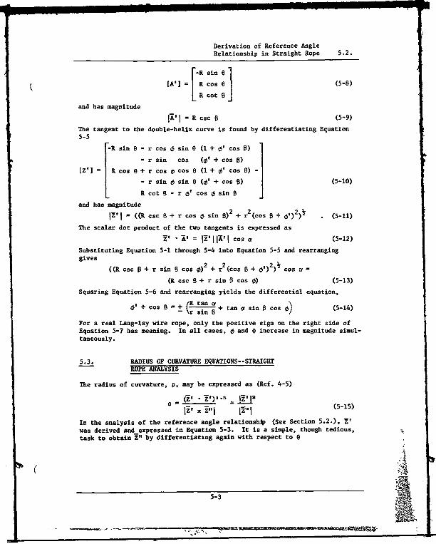
Derivation of Reference AngleRelationship in Straight Rope 5.2.
[A' = R cos 6 (5-8)
Rcot 8
and has magnitude
A' I = R csc 8 (5-9)
The tangent to the double-helix curve is found by differentiating Equation5-5
_-R sin e - r cos 0 sin Q (1 + 0' cos 8
- r sin cos (0' + cos 8)
[Z'] = R cos 6 + r cos 0 cos 6 (1 + 0' cos B) -
- r sin 0 sin 0 (01 + cos 8) (5-10)
L R cot 8 - r c5' cos 0 sin 0
and has magnitude
xi I = ((R csc B + r cos o sin 9)2 + r2(cos B + o,)2)• (5-11)
The scalar dot product of the two tangents is expressed as
V - ', = ' I W, I Cos a (5-12)
Substituting Equation 5-1 through 5-4 into Equation 5-5 and rearranginggives
((R csc 8 + r sin B cos 0)2 + r2 (Cos B + o')2) s =
(R csc 8 + r sin 0 cos 0) (5-13)
Squaring Equation 5-6 and rearranging yields the differential equation,
01 + cos B =+ (R---n a + tan a sin 0 cos 6_ (5-14)
_ r sinE 8tnsn~o
For a real Lang-lay wire rope, only the positive sign on the right side ofEquation 5-7 has meaning. In all cases, 0 and e increase in magnitude simul-taneously.
5.3. RADIUS OF CURVATURE EQUATIONS--STRAIGHTROPE ANALYSIS
The radius of curvature, p, may be expressed as (Ref. 4-5)
p = Cl.P 15=E
D I, i"1 I (5-15) PIIn the analysis of the reference angle relationship (See Section 5.2.), 7'was derived and-expressed in Equation 5-3. It is a simple, though tedious,task to obtain Z" by differentiating again with respect to 0
5-3
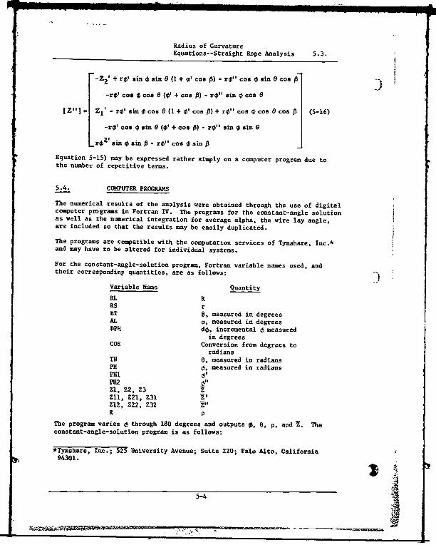
Radius of CurvatureEquations--Straight Rope Analysis 5.3.
"-Z2 ' + ro' sin sin (1 + , coB ) - ro"o coo Osin9cos -
-ro' cos 0 coo 9 (0' + coo A) - ro" sin 0 coo 9
[Z"] Zl' - ro.'simn cos e(1 + 0' cos A) + rol coB 0 cos e cos 1 (5-16)
-ro' cos 0 sin 0 (0' + cos P) - ro" sin 0 sin6
ro s. € inosin - ro" cos 0 sin
Equation 5-15) may be expressed rather simply on a computer program due tothe number of repetitive terms.
5.4. COMPUTER PROGRAMS
The numerical results of the analysis were obtained through the use of digitalcomputer programs in Fortran IV. The programs for the constant-angle solutionas well as the numerical integration for average alpha, the wire lay angle,are included so that the results may be easily duplicated.
The programs are compatible with the computation services of Tymshare, Inc.*and may have to be altered for individual systems.
For the constant-angle-solution program, Fortran variable names used, andtheir corresponding quantities, are as follows:
Variable Name Quantity
RL RRS rBT 8, measured in degreesAL r, measured in degreesDPH do, incremental 0 measured
in degreesCOE Conversion from degrees to
radiansTH 0, measured in radiansPH 6, measured in radiansPHI 6• 1
P11261Z1, Z2, Z3 ZZll, Z21, Z31 Z.Z12, Z22, Z32 Z"R P
The program varies 0 through 180 degrees and outputs 0, 0, p, and X. Theconstant-angle-solution program is as follows:
94301.
5-4
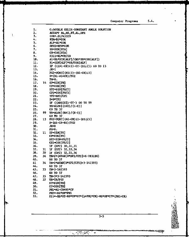
Computer Programs 5.4.
1. C:DOIJBLE HELIX-CONSTANT ANGLE SOLUTION2. ACCEPT RL,RS,BT,AL,DPH3. COE=-.017453294. BTA=BT*COE5. ALF=AL*COE6. DPHI=DPH*COE7. SB=-SIN[BTA]8. CB=COS[BTA]9. Z311=RL*CB/SB10. Al=RL*SIN[ALF] / (RS*SB*COS[ALT])11. B1=SIN[-ALF]*SB/COS[AIFI12. IF (((A1-CB)12).GT-(B1j2)) GO T0 1313. JK1l14. FG2=SQRT[ (Bl12)-(Al-CB)12]15. 9= (Bl-AI4CB) /FG216. P11=0.17. 14 SP-SIN[PH]18. CP=COS[PH]19. SP2=SIN[PH/2120. CP2=COS[PH/2]21. TP2=SP2/CP222. E=D*IT223. IF ((ABS[EIl-GT-) GO TO 9924. THl-ALOG[ (1+E)/(1-E)125. GO TO 3726. 99 TII=ALOG[(E+1)/(E-1)]27. GO TO 3728. 13 FG2=SQRT[(Al-CB)42-(Blj2)]29. D=(Al-CB-Bl)/FG230. JI=OO31. P11=0.32. 11 SP=sIN[PlI]33. CPcOS[PHI34. SP2=SIN4-PH/2]35. CP2=COSIPH/2136. IF (SP2) 30,31,3137. 31 IF (CP2) 32,33,3438. 30 IF (CP2) 32,35,3639. 36 TH--2*(ATAN[D*SP2/CP2]+6-283186)40. GO TO3741 34 TR-.2*ATAN[D*SP2/CP2]+3.141593)44. GO TO 3745. 33 TH-3414159346. GO TO 3747. 35 THg3*3.14159348. 37 TH=TH/FG249. ST-'SIN[TH]50. CT=COS[TH]51. PH1=Al-CBtBl*CP52.* PH2-Bl*SP*PHI53. Z11=-RL*ST-RS-CP*ST*(1+PHI*CB) -RS-SP*C-T* (PHI+CB)
5-5
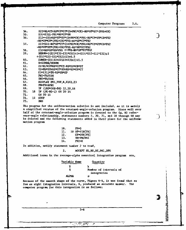
Computer Programs 5.4.
454. Z2IBRL*CT+RS*CP*CT*(l+PHI*CB) -gS*SP*ST* (PHl+CB)55. Z31-Z311-PHl*RS*CP*SB56. Z12=-Z21I+RS*SP*ST* (I+PH*CB)*PHI-RS*CP*ST*CB*PH2
-RS*CP*CT*(PHl+CB)*PHl-RS*SP*CT*PH257. Z22Z 11-RS*SP*CT*(l+PHI*CB)*PH1+RS*CP*CT*CB*PH2
-RS*CP*ST*(PHl+CB)*PH -RS*SP*ST*PH2
58. Z32RS*SP*SB*PH1 2-PHl-RS*SP*ST*PH259.: DENOGI ((Z21*Z32-Z31*Z22)42+(Z31*ZI2-ZII*Z32)4 2
+(ZII*Z22-Z21*Z12)42)O.560. ZUMER-(Z11t2+Z2142+Z3142)41.561. R=ZUHER/DENOM62. ZI=RL*CT*RS*CP*CT-RS*SP*CB*ST63. Z2=RL*ST+RS*CP*ST+RS*SP*CB*CT64. Z3=Z311*TH-RS*SB*SP65. PHI=PH/COE66. THT"TH/COE67. DISPLAY PHI,THT,R,Z1Z2,Z368. PH=PH-DPHI69. IF (180*COE-PH) 12,18,1870. 18 IF (JK-EQ-l) GO TO 1471. GO TO 1172. 12 STOP73. END
The program for the uniform-motion solution is not included, as it is merelya simplified version of the constant-angle-solution program. Since well overhalf of the constant-angle-solution program is devoted to the (0, 6) refer-ence-angle relationship, statements numbers 5, 70, 71, and 10 through 48 maybe deleted and the following statements added in their place for the uniform-motion program
10. PH1O11. 18 SP=SIN[FHJ12. CP-COS[PH]13. TH=PH/PHl14. PH2=0
In addition, modify statement number 2 to read,
2. ACCEPT RL,RS,BT,PH1,DPH
Additional terms in the average-alpha numerical integration program are,
Variable Name Quantity
T kS Number of intervals of
integrationALPHA a
Because of the smooth shape of the curve, Figure 4-4, it was found that asfew as eight integration intervals, S, produced an accurate answer. The !computer program for this integration is as follows:
5-6
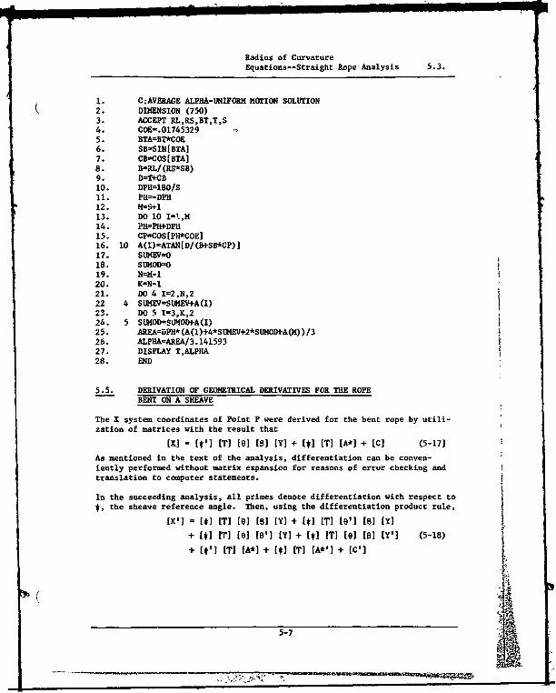
Radius of CurvatureEquations--Straight Rope Analysis 5.3.
I. C:AVERAWE ALPHA-UNIFORM MOTION SOLUTION2. DIMENSION (750)3. ACCEPT RL,RS,BT,T,S4. COEff.017453295. BTAffBT*COE6. SB=SIN[BTA]7. CBxzCOS[BTA]8. B=-RL/(RS*SB)9. D-T+CB10. DPH=180/S11. PH=-DPHr
12. M=S-113. DO 10 I=!,M14. PHfPH+DPH15. CP=COS[PH*COE]16. 10 A(I)=ATAN[D/(B+SB*CP)]17. SLEV=O18. SUMOI=O19. N=M-120. K=N-121. DO 4 I=2,N,222 4 SUMEV=SU•EV+A(I)23. DO 5 I=3,K,224. 5 SLUOD=SLNOD-A(I)25. AREA=DPH*(A(1)+4*SIHEV+2*SUMOD+A(M))/326. ALPHA=7ARFA/3.14159327. DISPLAY T,ALPHA28. END
5.5. DERIVATION OF GEOMETRICAL DERIVATIVES FOR THE ROPEBENT ON A SHEAVE
The X system coordinates of Point P were derived for the bent rope by utili-zation of matrices with the result that
[xI = [I'] [T] [0] [01 [Y] + [s] [T] [A*] + [C] (5-17]
As mentioned in the text of the analysis, differentiation can be conven-iently performed without matrix expansion for reasons of error checking andtranslation to computer statements.
In the succeeding analysis, all primes denote differentiation with respect to5, the sheave reference angle. Then, using the differentiation product rule,
Ix'] = [1] ITI [10 [s] [Y] + [M] IT] [e'] [9] [Y]
+ [*I [T] [e] [6'] [Y) + [*I [T] [e] [1] [Y'] (5-18)
+ (1'] IT] [A*] + [*I [T] [A*'] + [C']
5-7

Derivation of Geometrical DerivativesFor the Rope Bent on a Sheave 5.5.
where] cs * -sin * 0 J
[0 0 0J
[sin 6 -cos e 01(01 =9 cos o -sin 0 , where e' =K
0 0 0[o o oJE0 0 01
[0'] =' -sin 8 cos 0
0 -cos B -sin 0
2where K2 sin 0
+ Cs+ 02 + K2
[Y'] = ro cos 0 , where 0' =KIK
0. o
-sin 01
[A*'] RO'~ Cos 6
[so
[-Sin *[C'] = Rp cos *
L0]The definition of the other matrices may be found either in Section 5.1 or inthe body of the report. Expansion of individual terms in Equation 5-18 givesthe first geometrical derivative of X.The second geometrical derivative may be found by again applying the productrule, [I"] = [*"I IT] [01 [81 [YI + 2[*'] IT] [0'] [01 [Y]
+ 2[1'] IT) [01 [8'] [YI + 2[('1 iT] [1O] [] Y'I]
+ [1 IT] [e"] [81 [YI + [M]i I'] tell [t'] [I]
+ 2[]I [TI [6'] [81 [Y'] + [*I [T] [01 [8"] [YJ (5-19)
"+ 2[t] [T] [61 ['] Y'] + [#I IT] [01 [Y"]
+ [*"I [T] [A*] + 2[*'1 IT] [A*']
"+ [*1I T] [A*"] + [c"I ,
5-8

Derivation of Geometrical DerivativesFor the Rope Bent on a Sheave 5.5.
where E-cos sin t 01
[f"] = -sint -cos
0 0 0
[-COS e sin 0 0
["]= 8' -sin 0 -cos 0 0
0 0 0
[0 0 0 [ 0 o0[B"] = B" -sin 8 cos8 +B '2 0 -cos B -sin B
0 -cos 0 -sin 8] 1 sin 5 -cos q
and
0 KJ cos ° + cos0) + K2 ] + 2K4 sin + cos )B'T =R p2 2 '2
"L[ + cos 6) + K2 .
m0
[A"Y =R' 2 -si nj
r -cos "I
[A"]= RO -sin 0
L0r-Cos e[0 R [sin
P L0
5.6. BENDING-STRESS ANALYSIS COMPUTER PROGRAM
The results of the straight-rope and the rope-wrapped-on-a-sheave radii-of-curvature analyses were combined with the derived bending-stress equationsin a digital Fortran program in order to compute changes in bending stressas the rope is bent. As in previous programs, the statements are compatiblewith the services of Tymshare, Inc., and should be altered for individualcomputer systems.
Fortran variable names and the corresponding quantities they represent are:
Variable Name Quantity
RR,RL, RS, Y Rp, R, r, rwBT, AL a, • in degreesDPH, DYrH A0, AO in degrees
5-9

Bending-Stress Analysis Computer Program 55
Variable Name Quantity
E Young's Modulus3COE 17/1800
PH, 171 t, 0 in radianisTOPI F14 IZ12, Z22, Z32 VtmBOT1 z'R(J) pBT1, BT28.'Xll, X21, X31X(12, X(22, X(32TOP2
BOTr2RAD 0.,COANG Cos
The program varies 0 by A0 at various values of 0. During each iteration,p1, P,, ens § and a are calculated and 6, 0, and a are outputted. After 0has varied through 2nr, 9 is incremented by AG and then 0 is again variedthrough 2nr. This process continues until all desired values of 0 and ehave been investigated.
COMPUTER PROGRAM
1. C:WIRE ROPE BENDING STRESS ANALYSIS2. ACCEPT RR,RL,RS,BT,AL,DPH,DTH,E,Y3. COE=.017453294. BTA=ET*COE5. ALP=AL*COE6. SBT-SIN [ETA]7. CBT--COS[BTA]8. SA=SIN[ALP]9. GA=COS [ALP]10. THI=SQRT[ (RR/Ru4,2-l]*SBT/CBT11. PHl=SQRT[ ((RL*SA)/(aS*CA*SBT)..CBT)4 2- (SA*SBTICA)4 2]12. P11=013. TH0O14. 10 SP=SIN[PH]15. CP=COS[PHJ16. ST=-SIN[TH]17. CT=GOS[THi]18. TOPl=(RL/SBT+RS*uP*SBT)4 2+RSI2*(GBT+PH1).219. Z12=-RL*GCr-RS*Cp*Cr*(l+pul*CBT)+gRS*SP*sT* (PHI+CBT)+RS*Pal*
SP*ST* (liPHl*Cwr) -RS*PH1*CP*GT* (PH1+CBT)20. Z22s-RM$ST-RS*GP*ST*(l+Pli1*GgT)-aS*SP*CT*(PHol+CaT) RS*PH1*
SP*GT*(1+PHl*CBT) -RS*PHil*CP*ST* (PHl+CBT)21. Z32=RS*PHlI 2*SP*SBT22. BOTl=SQRT[Z1242+z2242+Z3242]23. R=TOP1/BOTl24. BTA=ATAN[TII1/(RR/l4LiCT)]
5-10
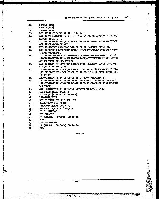
Bending-Stress Analysis Computer Program 5.5.
25. SB=SIN[BTA]26. CB=COS[BTA]
Q27. PHl=PHl*TH128. BT1-TH1112*ST/((RR/RLtCT)4 2+Th142)29. BT2=(Cr*((kIBI*-CT)42+4TH1A2).l?*ST42*(RRIRLtCr))*THl43I((P.R/
RL+CT)4 2+TH1I2)4 230. Xll=RS*(SB*SP-fH1* (ST*CP+CB*CT*SP)+BT1*SB*ST*SP-PHl* (CT*SP
+CB*ST*CP) )-..L*THl*ST31. X2l=RS* (CT*CP-CB*ST*SP-BTl*CB*SP-PHl*SB*CP)+BL*CT+RR32. X311=RS* (THI* (-cr*CP+CB*ST*SP)+BT1*SB*CT*SN-PHI* (SThSP-CB*C
T*Cp) ) -g$TH1*CT33. X12ftS*(-CT*CP+CB*ST*SP+2*BT1*CB*SP+2PH1*SB*CP+2*TH1*BT1*
SB*CT*SP+2*TH1*PHl* (ST*SP-CBr CT*CP)+BT2*SB*ST*SP4BTlI2*CB*ST*SP+2*PHI*BT1*SB*ST*CP)
34. X12=112+RS* (PHI 42* (-CT*CP+CB*ST*SP)+Th14 2* (-CT*CP+ST*SP) )+ftL* (-CT-Th1e 2*CT) -RR
35. X22=RS* (SB*Sp-2*fljI* ST*CP4+CB*CT*SP)+2*BT1*SB*ST*SP-2*PH1*(CT*SP+-CE*ST*CP)-BfT2*CB*SP+BTlI42*SB*SP-2*PH1*BT1*CB*CP+PHJ.2*SB*SP)
36. X22=X22+RS*Th14 2* (SB*ST*CP+SB*CThSP)-2*RL*THI*ST37. X32=RS* (-2*TH1*BT1*SB*S'r*SP+2*TH1*PH1* (CT*SP+CB*ST*CP)+B12
*SB*CI*SP4.BT1I 2*CB*CT*SP+2*PH1*BT1*SB*CT*CP+-PHI.12* (ST*CP+CB*CT*SP))
38. X32=X32+RS*TH14 2* (CB*STkCp4-B*CT*SP)+pL*TH14 2*ST39. T0P2=X1142+X2142+X314240. BOT2=SQRT[X124 2+X2242+X3242141. RAD=TOP2/30T242.* D0T=Z12*X12+Z32*X22-Z22*X3243. COANG=DOT/ (BOTI*B012)44. STR=-E*Y*(1/RAD)-C0AŽG/R)45. DISPLAY TH/COE,Fl1/COE,SYfR46. PH-PIWDPr*COE47. PHl=PHl/Th148. IF (PH.LE.(36CO~E)) G0 T0 1049. PIWO50. TH-tflW+DTH*C0E51. IF (TH.LE. (130*COE)) GO TO 1052. END
-END-
5-111
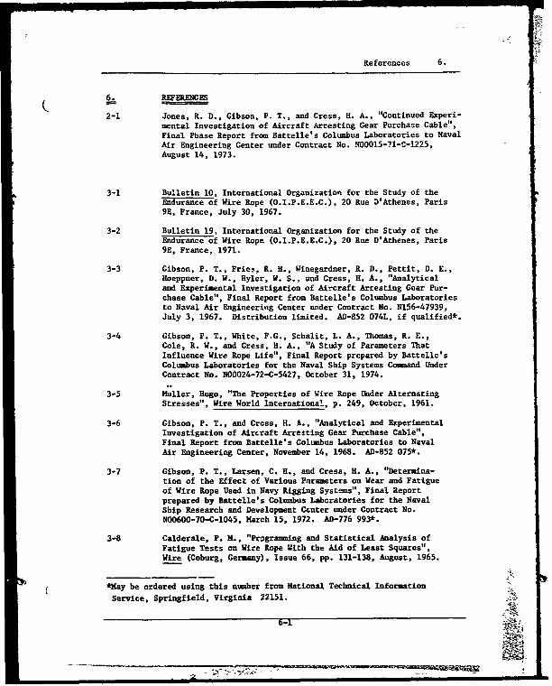
References 6.
_REFERENCES
2-1 Jones, R. D., Gibson, P. T., and Cress, H. A., "Continued Experi-mental Investigation of Aircraft Arresting Gear Purchase Cable",Final Phase Report from Battelle's Columbus Laboratories to NavalAir Engineering Center under Contract No. N00015-71-C-1225,August 14, 1973.
3-1 Bulletin 10, International Organization for the Study of theEndurance of Wire Rope (O.I.P.E.E.C.), 20 Rue D'Athenes, Paris9E, France, July 30, 1967.
3-2 Bulletin 19, International Organization for the Study of theEndurance of Wire Rope (O.I.P.E.E.C.), 20 Rue D'Athenes, Paris9E, France, 1971.
3-3 Gibson, P. T., Fries, R. H., Winegardner, R. D., Pettit, D. E.,Hoeppner, D. W., Hyler, W. S., and Cress, H. A., "Analyticaland Experimental Investigation of Aircraft Arresting Gear Pur-chase Cable", Final Report from Battelle's Columbus Laboratoriesto Naval Air Engineering Center under Contract No. N156-47939,July 3, 1967. Distribution limited. AD-852 074L, if qualified*.
3-4 Gibson, P. T., White, F.G., Schalit, L. A., Thomas, R. E.,Cole, R. W., and Cress, H. A., "A Study of Parameters ThatInfluence Wire Rope Life", Final Report prepared by Battelle'sColumbus Laboratories for the Naval Ship Systems Command UnderContract No. N00024-72-C-5427, October 31, 1974.
3-5 Huller, Hugo, "The Properties of Wire Rope Under AlternatingStresses", Wire World International, p. 249, October, 1961.
3-6 Gibson, P. T., and Cress, H. A., "Analytical and ExperimentalInvestigation of Aircraft Arresting Gear Purchase Cable",Final Report from Battelle's Columbus Laboratories to NavalAir Engineering Center, November 14, 1968. AD-852 075*.
3-7 Gibson, P. T., Larsen, C. H., and Cress, H. A., "Determina-tion of the Effect of Various Parameters on Wear and Fatigueof Wire Rope Used in Navy Rigging Systems", Final Reportprepared by Battelle's Columbus Lbcratories for the NavalShip Research and Development Center under Contract No.N00600-70-C-1045, March 15, 1972. AD-776 993*.
3-8 Calderale, P. M., "Programming and Statistical Analysis ofFatigue Tests an Wire Rope With the Aid of Least Squares",Wire (Coburg, Germany), Issue 66, pp. 131-138, August, 1965.
*May be ordered using this number from National Technical Information
Service, Springfield, Virginia 22151.
6-1
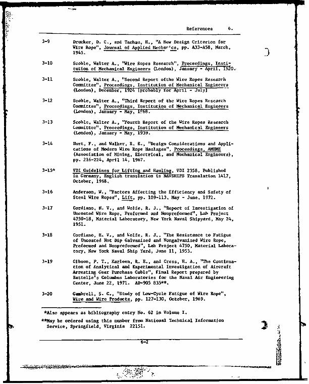
References 6.
3-9 Drucker, D. C., and Tachau, H., "A New Design Criterion forWire Rope", Journal of Applied Hecha'-cs, pp. A33-A58, March,1945.
3-10 Scoble, Walter A., "Wire Ropes Research", Proceedings, Insti-tution of Mechanical Engineers (London), January - April, 1920.,
3-11 Scoble, Walter A., "Second Report ofthe Wire Ropes ResearchCommittee", Proceedings, Institution of Mechanical Engineers(London), December, 1924 tprobably for April - Julyj
3-12 Scoble, Walter A., "Third Report of the Wire Ropes ResearchCommittee", Proceedings, Institution of Mechanical Engineers(London), January - May, 1.68.
3-13 Scoble, Walter A., "Fourth Report of the Wire Ropes Researchoimmittee", Proceedings, Institution of Mechanical Engineers
(London), January- May, 1939.
3-14 Hurt, F., and Walker, R. E., "Design Considerations and Appli-cations of Modern Wire Rope Haulages", Proceedings, AMDE(Association of Mining, Electrical, and Mechanical Engineers),pp. 216-224, April 14, 1967.
3-15* VDI Guidelines for Lifting and Hauling, VDI 2358, Publishedin Germany, English translation is NAVSHIPS Translation 1417,October, 1968.
3-16 Anderson, W., "Factors Affecting the Efficiency and Safety ofSteel Wire Ropes", Lift, pp. 109-113, Nay - June, 1972.
3-17 Cordiano, H. V., and Wolfe, R. J., "Report of Investigation ofUncoated Wire Rope, Preformed and Nonpreformed", Lab Project4750-18, Material Laboratory, New York Naval Shipyard, May 24,1951.
3-18 Cordiano, H. V., and Wolfe, R. J., "The Resistance to Fatigueof Uncoated Hot Dip Galvanized and Nongalvanized Wire Rope,Preformed and Nonpreformed", Lab Project 4750, Material Labora-tory, New York Naval Ship Yard, June 11, 1953.
3-19 Gibson, P. T., Karleen, R. E., and Cress, H. A., "The Continua-tion of Analytical and Experimental Investigation of AircraftArresting Gear Purchase Cable", Final Report prepared byBattelle's Columbus Laboratories for the Naval Air EngineeringCenter, June 22, 1971. AD-905 835**.
3-20 Gambrell, S. C., "Study of Low-Cycle Fatigue of Wire Rope",Wire and Wire Products, pp. 127-130, October, 1969.
*Also appears as bibliography entry No. 62 in Volume I.
**May be ordered using this number from National Technical InformationService, Springfield, Virginia 22151.
6-2

References 6.
3-21 Hagarman, P., and Kressley, L., "Evaluate, Test, and Manu-facture an Improved Wire Rope and Cable", Final Report on( Contract No. N065-92232 from Texas Instruments Corporation toU. S. Bureau of Ships, July 31, 1957. AD 819 202*
3-22 Macco, J., and Weiss, J., "Investigdtion of the Resistance toFatigue and Wear of Alumainum-Coated and Galvanized ImprovedPlow Steel Wire Rope", Lab Project 930-44, Naval AppliedScience Laboratory, Brooklyn, New York, January 16, 1968.
3-23 van de Moortel, D., "The Modern Development of Wire Rope",Wire, English Edition No. 48, August, 1960, and No. 49,October, 1960.
3-24 van de Moortel, "Two-Year Study Yields Data for EvaluatingCoated Cable", reprinted from Product Engineering, October 10,1966.
3-25** Selection of Wire Rope for Engineering Applications, Brita-shRopes Group, Wire Rope Technical Department, Carr Hill, Don-caster, England, 1967.
3-26 Matanzo, Frank, "Axial Fatigue of Wire Rope in Seawater",Offshore Technology Conference Preprints, Volume II, PaperNo. 1579, pp. 649-656, Offshore Technology Conference, Dallas,Texas, 1972.
3-27 Matanzo, Frank, and Heller, S. R., "Axial Fatigue of WireRope", Final Report from The Catholic University of America toNAVSHIPS, Contract No. N00024-70-C-5439, June 25, 1971.AD 726 457*.
3-28 Fleming, J. F., "Fatigue of Cables", Report on Project 1201-3N,to American Iron and Steel Institute from the School of Engin-eering of the University of Pittsburgh, June, 1974.
3-29 Reemsnyder, H. R., "The Mechanical Behavior of Steel Wire,Strand, and Rope", presentation to the Ad Hoc Committee onMechanical Rope and Cable, National Materials Advisory Board,National Research Council, June 6, 1972.
3-30 Berteaux, H. 0., and Walden, R. G., "An Engineering Programto Improve the Reliability of Deep Sea Moorings", Vol. 1,Marine Technology Society Preprints, Marine TechnologySociety, Washington, D. C., June 29 - July 1, 1970.
3-31 Heller, S. R., Jr., and Metcalf, John T., Jr., "Axial FatigueTests of Corroded Wire Rope Specimens", Final Report fromCatholic University of America to Naval Ships EngineeringCenter under Contract No. N00024-72-C-5394, April 25, 1974.AD 779 309*.
*Way be ordered usingthis number from National Technical InformationService, Springfield, Virginia 22151.
**Also appears as bibliography entry No. 8 in Volume I.
6-3
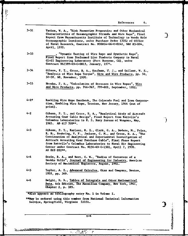
References 6.
3-32 Vachon, W. A., "Kink Formation Properties and Other MechanicalCharacteristics of Oceanographic Strands and Wire Rope", FinalReport from Massachusetts Institute of Technology to Woods Hole IOceanographic Institute, under Purchase Order 17052 of Officeof Naval Research, Contract No. N00014-66-C-0242, NRO 83-004,April, 1970.
3-33 , "Dynamic Testing of Wire Rope and Synthetic Rope",Final Report from Preformed Line Products Company to NavalCivil Engineering Laboratory (Port Hueneme, CA), underContract N62399-69-C-0013, January, 197n.
3-34 Gibson, P. T., Cress, H. A., Kaufman, L. J., and Gallant, W. E.,"Analysis of Wire Rope Torque", Wire and Wire Products, pp. 50,52-58, 60, November, 1970.
3-35 Hruska, F. H., "Calculation of Stresses in Wire Ropes", Wireand Wire Products, pp. 766-767, 799-801, September, 1951.
4-1* Roebling Wire Rope Handbook, The Colorado Fuel and Iron Corpora-tion, Roebling Wire Rope, Trenton, New Jersey, 1966 (out ofprint).
4-2 Gibson, P. T., and Cress, H. A., "Analytical Study of AircraftArresting Gear Cable Design", Final Report from Battelle'sColumbus Laboratories to U. S. Navy Bureau of Weapons, May,1965. AD 617 788**.
4-3 Gibson, P. T., Karleen, R. E., Clark, GC A., Dodson, M., Fries,R. H., Beuhring, V. F., Jackson, C. M., and Cress, H. A., "TheContinuation of Analytical and Experimental Invest.gation ofAircraft Arresting Gear Purchase Cable", Final Phase Reportfrom Battelle's Columbus Laboratories to Naval Air EngineeringCenter under Contract No. N156-69-C-1501, April 7, 1970.AD 869 092**.
4-4 Stein, R. A., and Bert, C. W., "Radius of Curvature of aDouble Helix", Journal of Engineering for Industry, AmericanSociety of Mechanical Engineers, August, 1962.
4-5 Taylor, A. E., Advanced Calculus, Ginn and Company, Boston,1955, pp. 369.
4-6 Dwight, H. B., Tables of Integrals and Other MathematicalData, 4th Edition, The Macmillan Company, New York, 1961,Chapter 2, p. 105.
*Also appears as bibliography entry No. 1 in Volume I.
**May be ordered using this number from National Technical InformationService, Springfield, Virginia 22151. 3
6-4 3
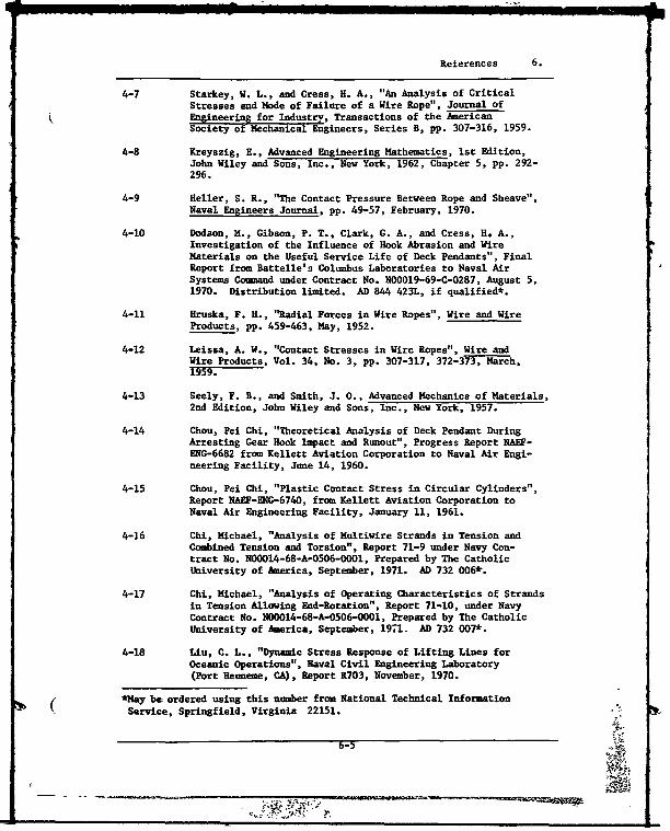
References 6.
4-7 Starkey, W. L., and Cress, H. A., "An Analysis of CriticalStresses and Node of Failure of a Wire Rope", Journal ofEngineering for Industry, Transactions of the AmericanSociety of Mechanical Engineers, Series B, pp. 307-316, 1959.
4-8 Kreyszig, E., Advanced Engineering Mathematics, 1st Edition,John Wiley and Sons, Inc., New York, 1962, Chapter 5, pp. 292-296.
4-9 Heller, S. R., "The Contact Pressure Between Rope and Sheave",Naval Engineers Journal, pp. 49-57, February, 1970.
4-10 Dodson, M., Gibson, P. T., Clark, C. A., and Cress, H. A.,Investigation of the Influence of Hook Abrasion and WireMaterials on the Useful Service Life of Deck Pendants", FinalReport from Battelle's Columbus Laboratories to Naval AirSystems Command under Contract No. N00019-69-C-0287, August 5,1970. Distribution limited. AD 844 423L, if qualified*.
4-11 Hruska, F. H., '"adial Forces in Wire Ropes", Wire and WireProducts, pp. 459-463, May, 1952.
4-12 Leissa, A. W., "Contact Stresses in Wire Ropes", Wire andWire Products, Vol. 34, No. 3, pp. 307-317, 372-37-3,March,195F.-
4-13 Seely, F. B., and Smith, J. 0., Advanced Mechanics of Materials,
2nd Edition, John Wiley and Sons, Inc., New York, 1957.
4-14 Chou, Pei Chi, "Theoretical Analysis of Deck Pendant DuringArresting Gear Hook Impact and Runout", Progress Report NAEF-ENG-6682 from Kellett Aviation Corporation to Naval Air Engi-neering Facility, June 14, 1960.
4-15 Chou, Pei Chi, "Plastic Contact Stress in Circular Cylinders",Report NAEF-ENG-6740, from Kellett Aviation Corporation toNaval Air Engineering Facility, January 11, 1961.
4-16 Chi, Michael, "Analysis of Multivire Strands in Tension andCombined Tension and Torsion", Report 71-9 under Navy Con-tract No. N00014-68-A-0506-0001, Prepared by The CatholicUniversity of America, September, 1971. AD 732 006*.
4-17 Chi, Michael, "Analysis of Operating Characteristics of Strandsin Tension Allowing End-Rotation", Report 71-10, under NavyContract No. NO0014-68-A-0506-O001, Prepared by The CatholicUniversity of America, September, 1971. AD 732 007*.
4-18 Liu, C. L., "Dynamic Stress Response of Lifting Lines forOceanic Operations", Naval Civil Engineering Laboratory(Port Heuneme, CA), Report R703, November, 1970.
*May be ordered using this number from National Technical Information( Service, Springfield, Virginia 22151.
6-5

References 6.
4-19 Choo, Young-il, and Casarella, M. J., "A Survey of AnalyticalMethods for Dynamic Simulation of Cable-Body Systems", Journalof Hydronautics, Vol. 7, No. 4, pp. 137-144, October, 1973.
4-20 Albertson, N. D., "A Survey of Techniques for the Analysis andDesign of Submerged Mooring Systems", Report R815, CivilEngineering Laboratory, Naval Construction Battalion Center,Naval Facilities Engineering Command, August, 1974. AD 786487-9W0*.
4-21 Choo, Y. I., and Casarella, M. J., "A Survey of AnalyticalMethods for Dynamic Simulation of Cable-Body Systems", TýeCatholic University of America Report 73-1, Prepared forOffice of Naval Research under Contract No. N00014-68-A-0506-0001, March, 1973.
4-22 Dillon, D. B., "An Inventory of Current Mathematical Models ofScientific Data-Cathering Moors", report by Hydrospace-Challenger,Inc., Rockville, Maryland, to Office of Naval Research underContract No. N00014-72-C-0361, February, 1973. AD 756 225*.
4-23 Coeller, J. E., and Laura, P. A., "A Theoretical and Experi-mental Investigation of Impact Loads in Stranded Steel CablesDuring Longitudinal Excitation", The Catholic University ofAmerica Report 70-2, Prepared for the Office of Naval Re-search under Contract No. N00014-68-A-0506-000l, April, 1970.
4-24 Schneider, L., Mahon, T., and Barton, L. C., "Tow Cable SnapLoads", Anerican Society of Mechanical Engineers, Paper 64-WA/UNT 8, presented at the Annual Meeting of AS E, November 29 -December 4, 1964.
4-25 Ringleb, F. 0., "Cable Dynamics", Report NAEF-ENC-6169, NavalAir Engineering Facility (Ship Installations, December, 1956.)
4-26 Mukherjee, S. N., "Vertical Vibrations of Rope Excited bySudden Increase in Tension", International Ropeway Review(now Lift), pp. 12-14, 28, October/December, 1970.
4-27 Dale, J. R., and McChandless, J. M., "Water Drag Effects ofFlow-Induced Cable Vibrations", Report No. NADC-AE-6731,U. S. Naval Air Development Center, Warminster, Pennsylvania,June, 1967. AD 654 906*.
4-28 Dale, J. R., "Determination of Normal Drag Coefficients forFlexible Cables", Report No. NADC-AE-6719, U. S. Naval AirDevelopment Center, Warminster, Pennsylvania, June, 1967.AD 654 906*.
*May be ordered using this number from National TechniLcal InformationService, Springfield, Virginia 22151.
6-6

References 6.
4-29 Ringleb, F. 0., "Notion and Stress of an Elastic Cable due
to Impact", Journal of Applied Mechanics, Transactions ofASME, American Society of Mechanical Engineers, pp. 417-425,
ieptember, 1957.
4-30 Ringleb, F. 0., "Cable Dynamics", Mechanical Design and SystemsHandbook, Section 31, McGraw-Hill Book Company, New York, 1964.
4-31 N& ihardt, G. L., Eslinger, N. E., and Sasaki, F. S., "An Analy-tical Approach to the Alleviation of Dynamic Tensions in AircraftArresting Gear Cables", Wright Air Development Report 58-217,Prepared by American Machine and Foundry Company for WrightAir Development Center, Air Research and Development Comand,U. S. Air Force, Wright-Patterson Air Force Base, Ohio, underContract No. AF33(616)-5282, Project 1351-60716, May, 1958.
4-32 Gibson, P. T., Alexander, G. H., and Cress, H. A., "Validationof Design Theory for Aircraft Arresting Gear Cable", FinalReport from Battelle's Coluabus Laboratories to Naval AirSystems Command, under Contract No. NOw 65-0503-c, January,1968. AD 665 328*.
5-1 Greenwood, D. T., Principles of Dynamics, First Edition, Pren-tice Hall, Inc., Englewood Cliffs, New Jersey, 1965, Chapter 7,pp. 297-300.
6-7

Alphabetical Index 7.
7. ALPHABETICAL INDEX Page
A
Aircraft Arresting-Gear Cable ....................................... 4-38Alignment, Sheave ................................................... 3-13Aluminized Wire ..................................................... 3-28Aluminum Sheaves .................................................... 3-19Analysis, Stress, of Wire Rope
Bending ......................................................... 4-1Contact ......................................................... 4-29Shear ........................................................... 4-34Tensile ......................................................... 4-1Torsion ......................................................... 4-34
Angles, Fleet, Effect of ............................................ 3-13Angles, Wrap, Effect of ............................................. 3-10Attachments, Effects of
on Axial Fatigue Life ........................................... 3-36on Bending Fatigue Life ......................................... 3-15
Axial Fatigue DataWire Rope ....................................................... 3-33Wire Strand ..................................................... 3-33
Axial Load Characteristics .......................................... 3-33Axial Stresses, Calculation of ...................................... 4-1
B
Bearing Pressure Ratio .............................................. 3-8Bending Fatigue Data, Wire Rope
-Reverse Bend ............................................... 3-18, 3-32Single Bend .................................. 3-2 to 3-17, 3-19 to 3-31
Bending Stresses, Calculation of .................................... 4-24Breakage, Wire, as a Function of Wrap Angle ......................... 3-12Breaking Strengths, Wire, Effects of
on Axial Fatigue Life ........................................... 3-39on Bending Fatigue Life ......................................... 3-14
Breaks, Wire, Identification of ..................................... 2-1Bright Wire ......................................................... 3-28
C
Cable, Aircraft Arresting-Gear ....................................... 4-38Carbon Steel Wire ................................................... 3-13
Cast Iron Sheaves ................................................... 3-19Coatings, Wire, Effects of
on Axial Fatigue Life............................................ 3-40on Bending Fatigue Life ......................................... 3-28
Coefficients, Drag, Cable ........................................... 4-39Complex Bending of Wire Segments .................................... 4-26Computer Programs ................................................... 5-4
Confidence Bands on Bending Fatigue Data ............................ 3-8
7-1
77 77
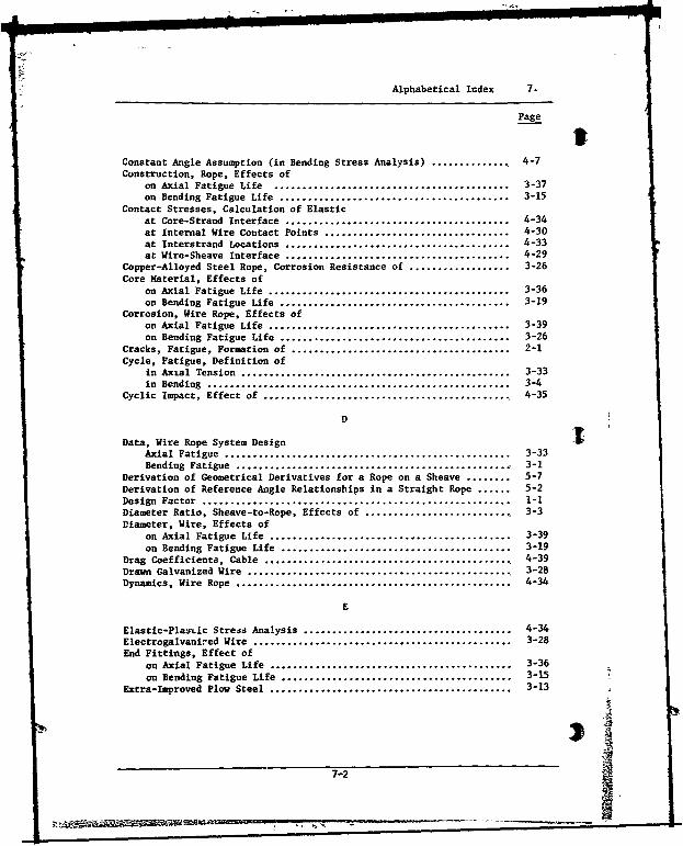
Alphabetical Index 7.
Page
Constant Angle Assumption (in Bending Stress Analysis) .............. 4-7Construction, Rope, Effects of
on Axial Fatigue Life .......................................... 3-37on Bending Fatigue Life ......................................... 3-15
Contact Stresses, Calculation of Elasticat Core-Strand Interface ........................................ 4-34at Internal Wire Contact Points ................................. 4-30at Interstrand Locations ........................................ 4-33at Wire-Sheave Interface ........................................ 4-29
Copper-Alloyed Steel Rope, Corrosion Resistance of .................. 3-26Core Material, Effects of
on Axial Fatigue Life ........................................... 3-36on Bending Fatigue Life ......................................... 3-19
Corrosion, Wire Rope, Effects ofon Axial Fatigue Life ........................................... 3-39on Bending Fatigue Life ......................................... 3-26
Cracks, Fatigue, Formation of ....................................... 2-1Cycle, Fatigue, Definition of
in Axial Tension ................................................ 3-33in Bending ...................................................... 3-4
Cyclic Impact, Effect of ............................................ 4-35
D
Data, Wire Rope System Design tAxial Fatigue ................................................... 3-33Bending Fatigue ................................................. 3-1
Derivation of Geometrical Derivatives for a Rope on a Sheave ........ 5-7Derivation of Reference Angle Relationships in a Straight Rope ...... 5-2Design Factor ....................................................... 1-1Diameter Ratio, Sheave-to-Rope, Effects of .......................... 3-3Diameter, Wire, Effects of
on Axial Fatigue Life ........................................... 3-39on Bending Fatigue Life ......................................... 3-19
Drag Coefficients, Cable ............................................ 4-39Drawn Galvanized Wire ............................................... .3-28Dynamics, Wire Rope ................................................. 4-34
E
Elastic-Plas*Lic Strejs Analysis ..................................... 4-34Electrogalvanired Wire .............................................. 3-28End Fittings, Effect of
on Axial Fatigue Life ........................................... 3-36on Bending Fatigue Life ......................................... 3-15 7
Extra-Improved Plow Steel ........................................... 3-13
7-2
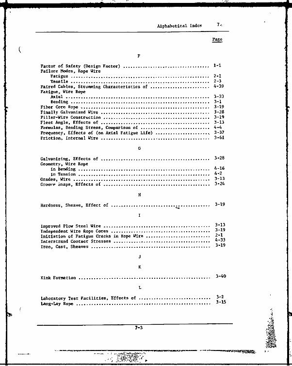
Alphabetical Index 7,
Page
F
Factor of Safety (Design Factor) ................................... 1-1Failure Modes, Rope Wire
Fatigue ........................................................ 2-1Tensile ........................................................ 2-3
Faired Cables, Strumming Characteristics of ........................ 4-39Fatigue, Wire Rope
Axial .......................................................... 3-33Bending ........................................................ 3-1
Fiber Core Rope .................................................... 3-19Finally Galvanized Wire ............................................ 3-28Filler-Wire Construction ........................................... 3-19Fleet Angle, Effects of ............................................ 3-13Formulas, Bending Stress, Comparison of ............................ 4-4Frequency, Effects of (on Axial Fatigue Life) ...................... 3-37Friction, Internal Wire ............................................ 3-61
G
Galvanizing, Effects of ............................................ 3-28Geometry, Wire Rope
in Bending ..................................................... 4-16in Tension ..................................................... 4-2
Grades, Wire ....................................................... 3-13Groove Shape, Effects of ........................................... 3-24
H
Hardness, Sheave, Effect of .......................... ............. 3-19
I
Improved Plow Steel Wire ........................................... 3-13Independent Wire Rope Cores ........................................ 3-19Initiation of Fatigue Cracks in Rope Wire .......................... 2-1Interstrand Contact Stresses ....................................... 4-33
Iron, Cast, Sheaves ................................................ 3-19
3
K
Kink Formation ..................................................... 3-40
L
Laboratory Test Facilities, Effects of ............................. 3-2Lang-Lay Rope ...................................................... 3-15
7-3
-v

Alphabetical Index 7.
Page I)Lay Angle and Direction, Effects of
on Axial Fatigue Life ......................................... 3-36on Bending Fatigue Life ....................................... 3-15
Lay Length, Measurement of Rope and Strand ........................ 3-54Life Factor ....................................................... 3-11Load Cycle Characteristics, Axial ................................. 3-33Load Level, Effect of
on Axial Fatigue Life ......................................... 3-33on Bending Fatigue Life ....................................... 3-5
Load Range, Effects of (on Axial Fatigue Life) .................... 3-35Longitudinal Forces Due to Rope Dynamics .......................... 4-35Lubrication, Effects of
on Axial Fatigue Life ......................................... 3-40on Bending Fatigue Life ....................................... 3-28
H
material, Cure, Effects ofon Axial Fatigue Life ......................................... 3-36on Bending Fatigue Life ....................................... 3-19
Material, Wire, Effects ofon Axial Fatigue Life .......................................... 3-37on Bending Fatigue Life ........................................ 3-13
Matrix Analysis (in Bending Stress Analysis) ...................... 5-14Maximum Load, Effect of (on Axial Fatigue Life) ................... 3-35
Mean Load, Effect of (on Axial Fatigue Life) ...................... 3-35
Metallic Cores .................................................... 3-19
Mechanical Properties of Rope Wire ................................ 3-13
Mild Plow Steel Wire .............................................. 3-13
Modes of Wire Failure ............................................. 2-1
Multiple Operation Strands ........................................ 3-19
N
Mickel-Alloyed Steel, Corrosion Resistance of ..................... 3-26
Nodal Angles, Sheave .............................................. 3-58
Nonrotating (Low Rotation) Ropes,Torsional Characteristics ..................................... 3-43
Ultimate Strength Under Rotation .............................. .3-42
Nylon-Jacketed Cable .............................................. 3-31
Nylon-Lined Sheaves ............................................... 3-25
0
P
Plastic Coatings .................................................. 3-31
Plasticity, Cross-Wire, Analysis of ............................... 4-34
Plow Steel ........................................................ 3-13
Polypropylene Cores ................................................ .-25
7-4
Alphabetical Index 7.
Page
Preforming, Effects of ............................................. 3-19Pressure, Rope-to-Sheave Bearing ................................... 3-8
Q
R
Radius of Curvature, Change in Rope WireComputer Program for Determination of .......................... 5-9Due to Bending Over a Sheave ................................... 4-23Due to Tensile Loading ......................................... 4-10
Range of Load, Effects of (on Axial Fatigue Life) .................. 3-35Ratio, Sheave-to-Rope Diameter, Effect of .......................... 3-3Regular-Lay Rope ................................................... 3-19Relative Mout
4n of Strands in a Rope ............................... 3-55
Reversed Bends, Effect of .......................................... 3-30Rotation, Rope. Effects of ......................................... 3-40
S
Shear Failures in Rope Wire ........................................ 2-2Shear Stresses, Calculation of ..................................... 4-34Sheave Hardness, Effects of ........................................ 3-19Sheave Throat Shape, Effects of .................................... 3-24Single Operation Strands ........................................... 3-15Socketing Technique, Effects of (on Axial Fatigue Life) ............ 3-36Statistical Variation in Bending Fatigue Data ...................... 3-8Strands, Axial Fatigue of Steel .................................... 3-33Strands, Number of (as it Affects Bending Fatigue Life) ............ 3-15Strength, Wire, Effects of
on Axial Fatigue Life .......................................... 3-37on Bending Fatigue Life ........................................ 3-13
Stress Analysis, Wire RopeBending ........................................................ 4-2Contact ........................................................ 4-29Shear .......................................................... 4-34Tensile ........................................................ 4-1Torsion ...................... ................................. 4-34
Strumming, Effects of .............................................. 4-36Suppression of Strumming ........................................... 4-38
Swaged Sockets, Effects of (on Axial Fatigue Life) ................. 3-37
T
Tensile Failures in Rope Wire ...................................... 2-3Tensile Stresses, Calculation of ................................... 4-1Throat Shape, Sheave, Effect of ..................................... 3-24
Torsional Characteristics of Various Rope Constructions .............. 3-41
Torsional Stresses, Calculation of ................................. 4-34
Torque, Wire Rope .................................................. .3-40
7<7-5 -
IAlphabetical Index 7.
Page
Translation of Coordinates (in Bending Stress Analysis ............ 5-1
Transverse Forces Due to Rope Dynamics ............................ 4-36
U
Uniform-Motion Assumption (in Bending Stress Analysis) ............ 4-8
V
W
Wire Coatings ..................................................... 3-28Wire Failure Modes................................................. 2-1Wire Sizesn........................................................ 3-19Wire Strengths ..................................................... 3-13Wire, Types of Rope ................................................ 3-13Wires, Arrangement of (in a Rope) ................................. 3-19Wrap Angle, Effects of ............................................ 3-10
x
Z -
Zinc Coatings ..................................................... 3-28
Zinc Sockets, Effect of (on Axial Fatigue Life) ................... 3-36
7-6 , J,.** 26


