A. INTRODUCTION General Design Criterion 53, "Provisions for Containment Testing and Inspection," of Appendix A, "General Design Criteria for Nuclear Power -Plants," to 10 CFR Part 50, "Domestic Licensing of Production and Utilization Facilities," requires, in part, that the reactor containment be designed to per mit (1) periodic inspection of all important areas and (2) an appropriate surveillance program. Regulatory Guide 1.35, "Inservice Inspection of Ungrouted Ten dons in Prestressed Concrete Containment Struc tures," describes a basis acceptable to the NRC staff for developing an appropriate inservice inspection and surveillance program for ungrouted tendons in prestressed concrete containment structures of light water-cooled reactors. This guide expands and clari fies the NRC staff position on determining prestres sing forces to be used for inservice inspections of prestressed concrete containment structures. The Advisory Committee on Reactor Safeguards has been consulted concerning this guide and has concurred in the regulatory position. Any information collection activities mentioned in this regulatory guide are contained as requirements in 10 CFR Part 50, which provides the regulatory ba sis for this guide. The information collection require ments in 10 CFR Part 50 have been cleared under OMB Clearance No. 3150-0011. USN-RC REGULATORY GUIDES Regulatory Guides are issued to describe and make available to the pub Ile methods acceptable to the NRC staff of Implementing specific parts of the Commission's regulations, to delineate techniques used by the staff In evaluating specific problems or postulated accidents, or to pro "vide guidance to applicants. Regulatory Guides are not substitutes for regulations, and compliance with them Is not required. Methods and solutions different from those set out in the guides will be acceptable If they provide a basis for the findings requisite to the issuance or continu ance of a permit or license by the Commission. This guide was Issued after consideration of comments received from the public. Comments and suggestions for Improvements In these guides are encouraged at all times, and guides will be revised, as ap propriate, to accommodate comments and to reflect new information or experience. Written comments may be submitted to the Regulatory Publications Branch, DFIPS, ADM, U.S. Nuclear Regulatory Commission, Washing ton, DC 20555. July 1990 .UIDE B. DISCUSSION The inspections of prestressed concrete contain ment structures (with greased or grouted tendons) are performed with the objective of ensuring that the safety margins postulated in the design of contain ment structures are not reduced under operating and environmental conditions. Of particular concern in the case of prestressed concrete containment struc tures is the possible degradation of the prestressing tendon system by corrosion. The recommended in service inspection programs of Regulatory Guides 1.35 and 1.90, "Inservice Inspections of Prestressed Concrete Containment Structures with Grouted Ten dons," are formulated to achieve this basic objective. The extent to which the programs can perform their intended function depends on the method of their implementation. Review of reports of some of the inspections per formed by licensees on greased tendons indicates that there are various ways (simple but imprecise) of com bining the losses in prestressing forces, giving a wide band of tolerance in comparing the measured results. Such a practice is not acceptable to the NRC staff because a real and substantial degradation of the ten don system may remain undetected. Regulatory Guide 1.35 recommends the compari son of measured prestressing forces with the predicted forces of randomly selected tendons. The predicted forces at a given time are based on the measurement of prestressing forces during installation minus the losses in the prestressing forces that were predicted to The guides are Issued in the following ten broad divisions: 1. Power Reactors 2. Research and Test Reactors 3. Fuels and Materials Facilities 4. Environmental and Siting 5. Materials and Plant Protection 6. Products 7. Transportation 8. Occupational Health 9. Antitrust and Financial Review 10. General Copies of issued guides may be purchased from the Government Printing Office at the current GPO price. Information on current GPO prices may be obtained by contacting the Superintendent of Documents, U.S. Government Printing Office, Post Office Box 37082, Washington, DC 20013-7082, telephone (202)275-2060 or (202)275-2171. Issued guides may also be purchased from the National Technical Infor mation Service on a standing order basis. Details on this service may be obtained by writing NTIS, 5285 Port Royal Road, Springfield, VA 22161. U.S. NUCLEAR REGULATORY COMMISSION REGULATORY ( OFFICE OF NUCLEAR REGULATORY RESEARCH REGULATORY GUIDE 1.35.1 (Task SC 807-4) DETERMINING PRESTRESSING FORCES FOR INSPECTION OF PRESTRESSED CONCRETE CONTAINMENTS
Transcript
A. INTRODUCTION
General Design Criterion 53, "Provisions for Containment Testing and Inspection," of Appendix A, "General Design Criteria for Nuclear Power -Plants," to 10 CFR Part 50, "Domestic Licensing of Production and Utilization Facilities," requires, in part, that the reactor containment be designed to permit (1) periodic inspection of all important areas and (2) an appropriate surveillance program. Regulatory Guide 1.35, "Inservice Inspection of Ungrouted Tendons in Prestressed Concrete Containment Structures," describes a basis acceptable to the NRC staff for developing an appropriate inservice inspection and surveillance program for ungrouted tendons in prestressed concrete containment structures of lightwater-cooled reactors. This guide expands and clarifies the NRC staff position on determining prestressing forces to be used for inservice inspections of prestressed concrete containment structures.
The Advisory Committee on Reactor Safeguards has been consulted concerning this guide and has concurred in the regulatory position.
Any information collection activities mentioned in this regulatory guide are contained as requirements in 10 CFR Part 50, which provides the regulatory basis for this guide. The information collection requirements in 10 CFR Part 50 have been cleared under OMB Clearance No. 3150-0011.
USN-RC REGULATORY GUIDES Regulatory Guides are issued to describe and make available to the pubIle methods acceptable to the NRC staff of Implementing specific parts of the Commission's regulations, to delineate techniques used by the staff In evaluating specific problems or postulated accidents, or to pro"vide guidance to applicants. Regulatory Guides are not substitutes for regulations, and compliance with them Is not required. Methods and solutions different from those set out in the guides will be acceptable If they provide a basis for the findings requisite to the issuance or continuance of a permit or license by the Commission.
This guide was Issued after consideration of comments received from the public. Comments and suggestions for Improvements In these guides are encouraged at all times, and guides will be revised, as appropriate, to accommodate comments and to reflect new information or experience.
Written comments may be submitted to the Regulatory Publications Branch, DFIPS, ADM, U.S. Nuclear Regulatory Commission, Washington, DC 20555.
July 1990
.UIDE
B. DISCUSSION
The inspections of prestressed concrete containment structures (with greased or grouted tendons) are performed with the objective of ensuring that the safety margins postulated in the design of containment structures are not reduced under operating and environmental conditions. Of particular concern in the case of prestressed concrete containment structures is the possible degradation of the prestressing tendon system by corrosion. The recommended inservice inspection programs of Regulatory Guides 1.35 and 1.90, "Inservice Inspections of Prestressed Concrete Containment Structures with Grouted Tendons," are formulated to achieve this basic objective. The extent to which the programs can perform their intended function depends on the method of their implementation.
Review of reports of some of the inspections performed by licensees on greased tendons indicates that there are various ways (simple but imprecise) of combining the losses in prestressing forces, giving a wide band of tolerance in comparing the measured results. Such a practice is not acceptable to the NRC staff because a real and substantial degradation of the tendon system may remain undetected.
Regulatory Guide 1.35 recommends the comparison of measured prestressing forces with the predicted forces of randomly selected tendons. The predicted forces at a given time are based on the measurement of prestressing forces during installation minus the losses in the prestressing forces that were predicted to
The guides are Issued in the following ten broad divisions:
1. Power Reactors 2. Research and Test Reactors 3. Fuels and Materials Facilities 4. Environmental and Siting 5. Materials and Plant Protection
6. Products 7. Transportation 8. Occupational Health 9. Antitrust and Financial Review
10. General
Copies of issued guides may be purchased from the Government Printing Office at the current GPO price. Information on current GPO prices may be obtained by contacting the Superintendent of Documents, U.S. Government Printing Office, Post Office Box 37082, Washington, DC 20013-7082, telephone (202)275-2060 or (202)275-2171.
Issued guides may also be purchased from the National Technical Information Service on a standing order basis. Details on this service may be obtained by writing NTIS, 5285 Port Royal Road, Springfield, VA 22161.
U.S. NUCLEAR REGULATORY COMMISSION
REGULATORY ( OFFICE OF NUCLEAR REGULATORY RESEARCH
REGULATORY GUIDE 1.35.1 (Task SC 807-4)
DETERMINING PRESTRESSING FORCES FOR INSPECTION OF PRESTRESSED CONCRETE CONTAINMENTS
have occurred since that time because of material and structural characteristics.
As various complex interacting phenomena are involved in the prediction of these losses, the chance is small that the measured prestressing force will agree quite closely with the predicted value. Hence, Regulatory Position 2.2 of this regulatory guide recommends the determination of limits (upper and lower) of prestressing force as a function of time. Revision 1 of Regulatory Guide 1.90 discusses this aspect briefly, as it is also relevant to the recommended inspection alternatives in that guide.
This supplementary guide is intended to clarify the NRC staff's position on the construction of tolerance bands for groups and subgroups of tendons so that the small-sample inspection program of Regulatory Guide 1.35 can provide better confidence in the integrity of prestressing tendons. The regulatory position of this guide recommends the factors to be evaluated and a method of using these factors in the construction of a tolerance band for a group of tendons having approximately the same time-dependent characteristics. The methods for evaluating the effects of these factors are discussed in this section of the guide.
The "Code for Concrete Reactor Vessels and Containments" (Ref. 1) enumerates the factors to be considered in determining the effective prestress (see Section CC-3542 of Ref. 1). However, it does not provide detailed consideration of these factors.
The methods suggested here are based on a search of relevant literature and on information provided to the NRC staff by applicants and their contractors. However, the listing of references in this guide does not constitute a blanket endorsement of the content of these references by the NRC staff.
1. MEASUREMENT OF PRESTRESSING FORCE
In general, the requirements of Section CC-4464 of the Code (Ref. 1) are adequate for measuring and verifying the seating force. However, the allowable discrepancy of +10% of the force calculated from the measured elongation and that obtained by a dynamometer or a pressure gauge is excessive. If the load/ elongation curve for the tendon system is based on a thorough evaluation of the prior tests using tensioning and measuring equipment similar to that proposed for use in construction, such a high discrepancy level is unwarranted. The NRC staff believes that this discrepancy level should not exceed ±5%. This recommendation is in agreement with the practice adopted by the American Concrete Institute (Ref. 2) and the Post-Tensioning Institute (Ref. 3).
During an inservice inspection, the liftoff (or load cell) measurements are compared against the initially measured forces. If the equipment used to make the measurements during the tensioning operation and during an inservice inspection have identical characteristics, the errors introduced by contributing factors such as reading accuracy or friction in the jacking system can be reduced to a minimum. The objective should be to use well-calibrated, accurate measuring equipment with sufficient sensitivity during both construction and inservice inspections to reduce the comparative errors caused by measurement to a negligible amount.
2. DETERMINATION OF PRESTRESSING LOSSES
The losses in prestressing force after the application of the force can be classified as follows:
1. Initial losses caused by:
"* Slip at anchorages "* Friction between the tendon and the tendon
duct at areas of contact "* Elastic shortening and effect of sequence of
stressing the various tendons.
2. Time-dependent losses caused by:
0
0
S
Shrinkage of concrete Creep of concrete Relaxation of prestressing steel.
3. Other losses caused by:
"* Failure of tendon elements from corrosion or material deficiency
"* Effects of variations in temperature.
These losses are discussed in Regulatory Position 2 together with the methods of determining their magnitude. Regulatory Position 2 pertains only to the prestressed concrete containment structures typically used for light-water reactors. For containments that operate at sustained high temperatures, the timedependent characteristics need to be evaluated at correspondingly high temperatures.
C. REGULATORY POSITION
The following minimum standards should be followed in the design and construction of prestressed concrete containment structures for the inspection programs described in Regulatory Guide 1.35 (Revision 3).
1. MEASUREMENT OF PRESTRESSING FORCE
The procedure of Code Section CC-4464 (Ref. 1) should be followed in measuring loads and extensions during tensioning, as supplemented by the following:
1.35.1-2
1. A minimum of three readings of loads and extensions at approximately equally spaced levels of load should be recorded before the final seating of the tendon.
2. If the discrepancy between the measured extension at the final seating force and the extension determined from the average tendon force along the length of a tendon exceeds 5%, the cause of such discrepancy and the corrective actions taken should be recorded. The extension corresponding to the average tendon force may be determined by calculation or from a tendon load-extension diagram provided by the tendon manufacturer.
The objective should be to use well-calibrated, accurate measuring equipment with sufficient sensitivity during both construction and inservice inspections to reduce the comparative errors caused by measurement to a negligible amount.
2. DETERMINATION OF PRESTRESSING
LOSSES
The following regulatory positions apply only to the prestressed concrete containment structures typically used for light-water reactors. For containments that operate at sustained high temperatures, the timedependent characteristics need to be evaluated at correspondingly high temperatures.
2.1 Initial Losses
The initial seating force (F,) should be modified - to allow for the following influences:
1. A known amount of slip at anchorage (if any)
2. A loss caused by elastic shortening of the structure, including the effects of sequence of tensioning by the method discussed here or by any other appropriate method.
3. Influence of wire breakage during construction. The extent of wire breakage should not exceed the allowance made in the design.
Loss from slip at anchorages should be determined based on prior experience and the testing history of the prestressing system to be used. The influence of slip at anchorages should be allowed for in the computation of initial prestressing forces.
Coefficients for determining the losses from friction should be determined before the start of the installation and should be verified and modified (if necessary) during the construction. In comparing the liftoff (or load cell) forces for ungrouted tendons, friction loss need be considered only for the fixed ends of tendons that have been tensioned from one end. For the purposes of inspecting (or monitoring) ungrouted tendons, consideration of this loss can be avoided by comparing forces at tensioned ends.
If all tendons in a specific direction (hoop, vertical, etc.) are prestressed simultaneously, the loss of
prestressing force from elastic shortening (FLES) can be given by:
Fo FLES = x EpAp
AcnEc + AsEs + ApEP + AIEI + AdEd
where
F0 is the initial seating force
Aen is the net concrete area
A,, Ap, Al, Ad
E,, Es, Ep, El, Ed
are the areas of reinforcing steel, prestressing steel, liner, and duct, respectively
are the moduli of elasticity of concrete, reinforcing steel, prestressing steel, liner, and duct, respectively.
However, the number of tendons to be prestressed is large, and the prestressing operation is performed in a systematic sequence so that the structure is more or less symmetrically prestressed during the process. Thus, the first tendons that are tensioned undergo a full loss from the subsequent elastic shortening of the structure, while the tendons that are tensioned last undergq almost no loss from elastic shortening. For all practical purposes, the loss of prestressing force from elastic shortening can be estimated and accounted for by using the following linear relationship:
F nLS = N FLES LES N
where N represents the total number of tendons in a particular direction, n represents the sequential number of a randomly selected tendon to be tensioned in that direction, and nr represents the number of ten
dons to be tensioned after the n1h tendon, i.e., nr =
N-n.
If the sequences of tensioning tendons in differ
ent directions are intermingled, the stresses produced in one direction by the tendons tensioned in the other directions must be considered.
Thus it is essential that the complete history of
tensioning a tendon be recorded, including its seating
force F 0 , the number of tendons tensioned before and after it, and any provision to account for the slip at anchorages. The modified initial prestressing force
Fi at the tensioned end can be calculated and re
corded as:
n n n F =F -F -FLSA i 0 LES
where FLSA is the loss of prestressing force due to
slip at anchorages.
35.1-3
L
2.2 Time-Dependent Losses
Limits (high and low) on expected timedependent losses at the end of the service life of the structure (generally 40 years), as well as those at one year after prestressing, should be established considering the variations in the following factors:
1. The extent of shrinkage of the structure contributing to the prestress losses. Table 1 may be used in the absence of specific data.
2. The effect of creep deformation on prestressing force. The method given in Appendix A of this guide or a similar method may be used to determine the creep deformation.
3. The effect of relaxation of stress in prestressing tendons. Reference 1 states that a minimum of three 1000-hour relaxation tests should be performed for the prestressing steel proposed for use.
Table 1. Variation of Shrinkage Strain With Relative Humidity
Mean Daily Relative 40-Year Shrinkage Strain2
Humidity,1 Annual %
Under 40% 130 x 10-6
40 to 80% 100 x 10-6
Above 80% 50 x 10-6
1Mean daily relative humidities for various areas in the U.S. can be found on Map 46 of Reference 4. 2These values are applicable to containments in which inside operating temperatures do not exceed 120 0 F (49*C) and that are subject to the ambient outside environment. The maxi
mum value of 130 x 10-6 may be substantially increased if the containment is exposed to a controlled dry high-temperature environment after completion of prestressing.
2.2.1 Effect of Shrinkage of Concrete
The schedule of construction of a typical prestressed concrete containment is such that a substantial portion of the expected long-term shrinkage will have taken place before the structure is prestressed. Reference 5 presents formulas for predicting the long-term shrinkage based on the assumption that the shrinkage approximately follows the laws of diffusion and supports the formulas by experimental investigation. An appropriate extrapolation of these formulas (for the volume-to-surface ratio of the structure in excess of 24 in. (60 cm) and the contributing shrinkage as that occurring 100 days after the average time of construction of the structure) would yield a value of 100 x 10-A, which is considered to be a reasonable value at a temperature of 70 0 F (21*C) and a relative humidity of 50%. The safety analysis reports
of several plants' indicate that a 40-year shrinkage value of 100 x 10-s has been used by the applicants.
This value, however, needs to be modified to account for the significantly higher shrinkage in a lowhumidity environment and the significantly lower shrinkage in a high-humidity environment. Table 1 provides typical shrinkage values that could be used for computation of prestressing losses caused by shrinkage.
2.2.2 Effect of Concrete Creep
One of the most significant and variable factors in the computation of time-dependent losses in prestressed concrete containment structures is the influence of concrete creep. Creep is thought to consist of two components: basic creep and drying creep. Drying creep, also sometimes termed stress-induced shrinkage, is thought to be due to the exchange of moisture between the structure and its environment. Its characteristics are considered to be similar to those of shrinkage, except that they represent an additional moisture movement resulting from the stressed condition of a structure. The amount of drying creep depends mainly on the volume-to-surface ratio of the structure and the mean relative humidity of the environment. For prestressed concrete containment structures having a volume-to-surface ratio in excess of 24 in. (60 cm), the relative influence of drying creep (compared to basic creep) is negligible as indicated by Figure 9 of Reference 5.
The significant parameters that influence the magnitude of basic creep can be summarized as follows:
1. Concrete mix-cement and aggregate type; proportion of cement, water, and aggregates; and the influence of admixtures.
2. Age at loading-The basic creep value is a function of the degree of hydration that has taken place at the time of loading.
3. The magnitude of the average sustained stress.
4. Temperature.
Almost all investigators support the assumption that basic creep varies linearly with the intensity of sustained stress, as long as the average stress level in the concrete is not greater than 40% of the ultimate strength of the concrete. The specific creep is thus defined as the ratio of total creep to the average stress intensity.
A literature review of the effect of temperature on basic creep (sealed or water-stored concrete specimens) is compiled in Reference 6. The average temperature of a prestressed concrete containment structure could vary between 40*F (5*C) and 100*F (38*C). Basic creep is shown to vary linearly with
'Turkey Point, Midland, Bellefonte, Three Mile Island.
1.35.1-4
temperature in this range of temperatures. Hence, if the basic creep is evaluated at approximately 70 0F (21QC), it should represent overall deformation caused by creep of concrete.
An acceptable method of determining basic creep at various times for a given concrete mix as a function of age at loading is provided in Appendix A to this guide. The method is based on concepts and equations derived by Hansen (Ref. 7) from a rheological model representing creep of concrete. Reference 8 uses the method of Reference 7 in determining long-term creep for a given concrete mix. Most investigators agree that there is no one formula that can be generally applicable in determining the long-term creep for various concrete mixes. Hence Appendix A recommends a method of predicting the long-term basic creep from the results of short-term creep tests. Other methods such as those described in References 9, 10, and 11 may be used if demonstrated to be appropriate for predicting long-term basic creep.
Short-term creep tests are generally performed during the construction of a nuclear power plant. The extrapolated creep values consistent with the average time of the loading of the structure may not be available during the preliminary design stages. A conservative estimate of creep values may be obtained from previous experience or from creep tests on similar concretes. However, these values should be modified to estimate the tolerance band for the prestressing force to be used for comparison of the measured prestressing forces during inservice inspections. The modifications should include the extrapolated creep values in light of the actual average age of the concrete at the time the containment is prestressed.
2.2.3 Effect of Relaxation of Prestressing Steel
The stress relaxation properties of prestressing steel vary with its chemical composition and thermal/ mechanical treatment. Manufacturers should be able to provide data on the long-term loss in prestressing steel stress from pure relaxation. Section CC-2424 of Reference 1 requires a minimum of three 1000-hour relaxation tests for the prestressing steel proposed for use. There should be a sufficient number of data points in each of the three tests to extrapolate the 1000-hour pure relaxation data to the life of the structure. An appropriate model (Refs. 12, 13, 14) should be selected for the determination of the "bestfitting" line for the purpose of extrapolation.
2.3 Losses Caused by Tendon Degradation
Most applicants make allowance for breakage of wires on an overall basis as well as on a localized basis. Such an allowance in the design of the containment would allow a breakage of a few wires during
construction without need for replacing these wires. For a tendon with a few broken wires, care should be taken not to overstress intact wires to bring the tendon force to a prescribed value. Instead, the tendon should be extended to the same level as other similar tendons (without broken wires). The procedure will leave the tendon at a prestress level lower than the prescribed (generally 70% of the guaranteed ultimate tensile strength (GUTS)) level. This is acceptable provided the design includes an allowance for the breakage of wires.
2.4 Effects of Variations in Temperature
Of particular importance for the purpose of comparing the prestress forces is the effect of differences between the average temperature of the structure during installation and that during inspections. Localized hot spots and temperature variations along the length of a tendon can cause variations in the force along the length of the tendon. The differences between the coefficients of expansion or contraction of concrete and steel can also cause modifications of tendon forces. These effects, as appropriate, should be considered in comparing the measured prestressing forces with the predicted forces.
3. GROUPING OF TENDONS
3.1 Basic Grouping of Tendons
The basic grouping of tendons for the purpose of developing tolerance bands should consider:
1. The geometric configuration of tendons with respect to the structure, e.g., vertical, hoop, dome, inverted U, and
2. The similarity in time-dependent characteristics. This may involve dividing the above configuration group (e.g., vertical, hoop, dome, and inverted U) into additional groups.
The significant variable affecting the timedependent prestressing force of tendons would be the effect of concrete creep. If the concrete mix characteristics and the curing conditions are assumed to be about the same during the entire period of construction of a containment structure, the parameters introducing variations in creep are (1) average compressive stress and (2) age of concrete at the time of prestressing. For example, in a shallow-dome containment structure, if the design requires that the meridional compressive stresses in the cylinder be half those in the hoop direction, the creep strains affecting the losses in prestressing would be proportional to their compressive stresses. Similarly, at the time of prestressing, the dome concrete might have aged three months, while the cylinder concrete might have aged six months or more. These parameters would affect the losses in prestressing forces in tendons and should be considered in grouping the tendons according to the similarity of their
35.1-5
time-dependent characteristics and in prescribing the tolerance band for prestressing forces in these tendons.
3.2 Subgroups of Tendons
The basic groups may be divided further into subgroups to account for the differences in instantaneous elastic shortening during the transfer of prestressing force and to account for the differences in initial prestressing forces (Fi) caused by differences in instantaneous elastic shortening during transfer. To account for the differences in initial prestressing forces Fi, a tabulation of Fi for each tendon in a group may serve the same purpose as subgrouping.
In short, the intent of any adopted procedure should be to track the individual prestressing forces as precisely as possible with the current state of the art in predicting these forces, so that when a tendon is selected randomly during an inspection its measured values can be compared with its prescribed tolerance band.
4. CONSTRUCTION OF TOLERANCE BANDS
Tolerance bands for groups and subgroups of tendons should be constructed and should be used for comparison of measured prestressing forces with the forces predicted for the time of inspection.
It is recognized that each of the factors affecting the time-dependent characteristics of tendon forces are subject to variations. To account for these variations in prescribing the tolerance band, the following method is recommended:
1. Determine Shrinkage. Table 1 provides the 40-year shrinkage strains in relation to the humidity level at the location of the structure. To allow for the associated uncertainty in the assumed values, strain should be varied by ±20%. The shrinkage strains at any time between the time of prestressing (consider zero shrinkage at t = 10 days) and 40 years can be estimated by considering shrinkage strain to vary linearly with the logarithm of time.
2. Determine Creep. The creep strains at any time after prestressing can be determined by the method of Appendix A. The high and low creep strains can be determined by increasing the extrapolated creep values by 25% and decreasing them by 15%, respectively (see Appendix B for illustrative example).
3. Determine Relaxation of Prestressing Steel. Provide a ±15% variation in relaxation values obtained by extrapolation of 1000-hour tests.
The first inservice inspection needs to be performed one year after the Initial Structural Integrity Testing (ISIT) of the containment. Hence, the period of interest from the point of view of inservice inspection is nominally between 1 year and 40 years after prestressing.
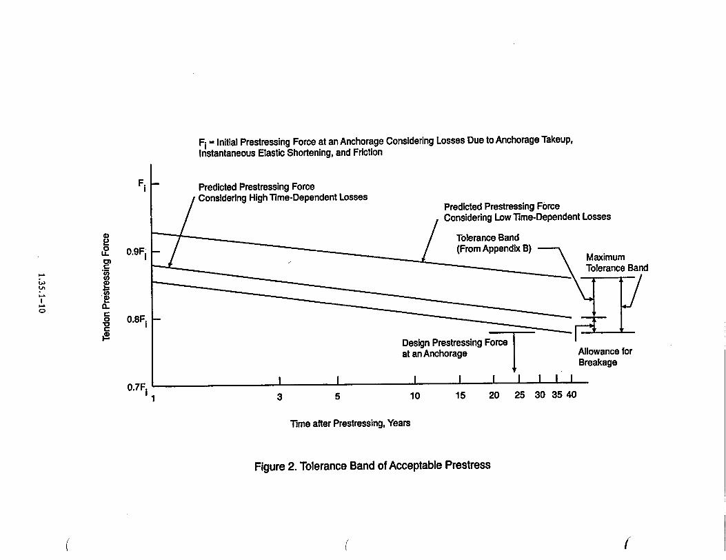
The upper and lower bounds for prestressing forces at 1 year and 40 years after prestressing can be found by adding up the low and high losses and subtracting them from Fi. For the purpose of constructing tolerance bands for various groups of tendons, it is sufficiently accurate to consider prestressing force to vary linearly with the logarithm of time.
In lieu of the variations indicated above, the designer may use the conservatively estimated design values as the base values for the time-dependent factors. In that case, the individual predicted tendon prestressing force at 1 year and 40 years can be determined using the base value as illustrated in Appendix B. The line drawn using these values should be considered as the lower bound. The upper bound can be arbitrarily drawn by plotting a line parallel to the lower bound and starting at 0.93F1 i at 1 year. This method can be used for the operating plants.
The upper line of the tolerance band is not critical from a safety point of view. However, this line allows the designer to establish a maximum variation line. If the prestressing of a tendon lies above this line, it is prudent to investigate the measurement technique and the pattern of losses in adjoining tendons.
D. IMPLEMENTATION
The purpose of this section is to provide information to applicants and licensees regarding the NRC staff's plans for using this regulatory guide.
Except in those cases in which the applicant or licensee proposes an acceptable alternative method for complying with specified portions of the Commission's regulation, the methods described herein will be used in the evaluation of inservice inspection and surveillance programs for the following nuclear power plants using prestressed concrete containments with ungrouted tendons:
1. Plants for which the construction permit or design approval is issued after July 31, 1990.
2. Plants for which the licensee voluntarily commits to the provisions of this guide.
1.35.1-6
APPENDIX A
DETERMINATION OF BASIC CREEP STRAINS FOR PRESTRESSED CONCRETE CONTAINMENT STRUCTURES
Recommended creep formula
i 1 (-to)cc•.e = A I -]e- + Bloglo t f L Jto
where
t = time (after average time of concrete placement) when creep value is desired, in days
to = time of loading after average time of concrete placement, in days
f, = average sustained concrete stress
Ec = creep strain at time t when the age of concrete at loading is to
A,B are constants to be determined from tests.
To determine the value of constants A and B,
the following' short-term creep tests are recommended:
Age at loading
to
30
90
180
Minimum Observations at
to tl t2 t3 t4 t 5
30 31 45 90 150 210
90 92 110 150 210 270
180 185 210 240 300 360
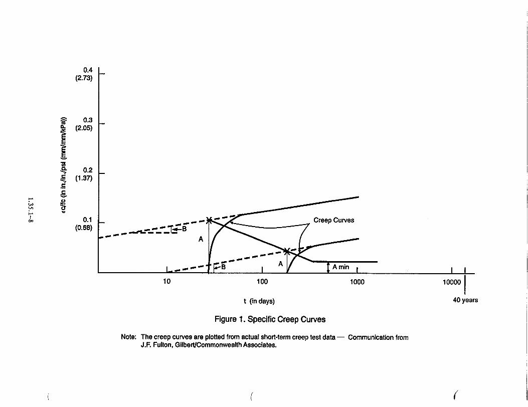
The constants A and B should be determined from creep strains at tl,t2, t3, t4, and t5 for each to by plotting the measured specific creep (cc) against
fC
t on a semi-logarithmic paper (see Figure 1). The value of B would essentially remain the same for all
values of to. The value of A for various values of to
can be determined as shown in Figure 1. For to values greater than 365 days, the A value determined at 365 days should be used.
The short-term creep tests should be performed according to the test method of Reference 15. To make the creep test results representative of creep deformations in a containment structure, the referenced test method should be used with the following specific provisions:
a. Section 3.1: The length of specimens should be 16 ± 1/16 in. (40 + 0.16 cm).
b. Section 3.2: The concrete mix should be the same as that proposed for use in the construction of the containment.
c. Section 3.3: Companion identical specimens
corresponding to each to may be used to observe the deformations of unloaded specimens.
d. Section 4.2: Mass curing (sealed specimen) conditions should be used during storage and testing. (The method used for the "as cast" condition in Ref
erence 16 is a good example.)
e. Section 5.1: Load the specimens to maintain a sustained stress of 30% of the design compressive strength of concrete.
f. Section 6.1: Subtract the instantaneous elastic strain taken at time to and the strain on the un
loaded specimen from the subsequent total strain measurements to arrive at creep strain (cc).
1.35.1-7
0.4 (2.73)
S0.3 (2.05)
.• 0.2 (1.37)
0 0.1 (0.68) Creep Curves
- - A
L-- " •B A A Imin I I
10 100 1000 10000
t (in days) 40 years
Figure 1. Specific Creep Curves
Note: The creep curves are plotted from actual short-term creep test data - Communication from J.F. Fulton, Gilbert/Commonwealth Associates.
( ((
APPENDIX B
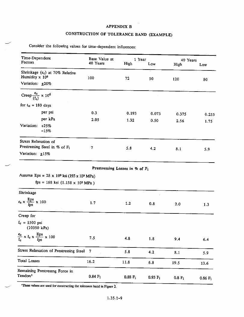
CONSTRUCTION OF TOLERANCE BAND (EXAMPLE)
Consider the following values for time-dependent influences:
Time-Dependent Base Value at 1 Year 40 Years Factors 40 Years High Low High Low
Shrinkage (Ec) at 70% Relative Humidity x 106 100 72 50 120 80 Variation: ±20%
Creep--c x 106
(fe) for to = 180 days
per psi 0.3 0.193 0.073 0.375 0.255 per kPa 2.05 1.32 0.50 2.56 1.75
Variation: +25%
-15%
Stress Relaxation of Prestressing Steel in % of Fi 7 5.8 4.2 8.1 5.9
Variation: ±15%
Prestressing Losses in % of Fi
Assume Eps = 28 x 103 ksi (193 x 103 MPa)
fps = 168 ksi (1.158 x 10³ MPa)
Shrinkage
es X x 100 1.7 1.2 0.8 2.0 1.3 fps
Creep for
fc = 1500 psi
(10350 kPa) cc Eps
fcx - x 100 7.5 4.8 1.8 9.4 6.4 4Cs
Stress Relaxation of Prestressing Steel 7 5.8 4.2 8.1 5.9
Total Losses 16.2 11.8 6.8 19.5 13.6
Remaining Prestressng Force in Tendon1
0.84 Fi 0.88 F1 0.93 Fi 0.8 Fi 0.86 Fi
'These values are used for constructing the tolerance band in Figure 2.
1.35.1-9
F, - Initial Prestressing Force at an Anchorage Considering Losses Due to Anchorage Takeup, Instantaneous Elastic Shortening, and Friction
Predicted Prestressing Force Considering High Time-Dependent Losses
Predicted Prestressing Force Considering Low Time-Dependent Losses
3 5 10 15 20 25 30 3540
Time after Prestressing, Years
Figure 2. Tolerance Band of Acceptable Prestress
((
FI
LI
Lu
UIM .G
C (0
I
0==
0 o
0..
0.9Fi
0.8FI
0.7Fi L 1i
REFERENCES
1. American Concrete Institute and American Society of Mechanical Engineers Subcommittee on Nuclear Power, "Code for Concrete Reactor Vessels and Containments," ACI-359, 1986.
2. American Concrete Institute, "Building Code Requirements for Reinforced Concrete," ACI-318, Revised periodically.
3. Post-Tensioning Institute, "Post-Tensioning Manual," Phoenix, AZ, 1986.1
4. J. L. Baldwin, "Climates of the United States," U.S. Department of Commerce, Washington, DC, December 1974.2
5. T. C. Hansen, A. H. Mattock, "Influence of Size and Shape of Member on the Shrinkage and Creep of Concrete," Journal of the American Concrete Institute, Proceedings Vol. 63, February 1966. Also published as PCA Development Bulletin D103.
6. H. G. Geymayer, "Effect of Temperature on Creep of Concrete, A Literature Review," Paper 31 of ACI SP-34, "Concrete for Nuclear Reactors," Vol. 1, American Concrete Institute, 1972.
7. T. C. Hansen, "Creep and Stress Relaxation of Concrete," Swedish Cement and Concrete Research Institute, Stockholm, 1960.3
8. "Report on Recommended Concrete Creep and Shrinkage Values for Computing Prestressing Losses," by Schupack and Associates. This nonproprietary report is filed in the NRC Public Document Room as Appendix 5J in Amendment 2 of the "Preliminary Safety Analysis Report for the Three Mile Island Nuclear Power Station, Unit 2," June 1968, Docket No. 50-320.4
9. I. J. Jordann, C. L. England, M. M. A. Khalifa, "Creep of Concrete: A Consistent Engineering Approach," Journal of the Structural Division of the American Society of Civil Engineers, March 1977.
10. E. Cinlar, Z. P. Bazant, E. Osman, "Stochastic Process for Extrapolating Concrete Creep,"
Journal of the Engineering Mechanics Division of the American Society of Civil Engineers, December 1977.
11. J. W. Chaung, T. W. Kennedy, E. S. Perry, "An Approach to Estimating Long-Term Multiaxial Creep Behavior from Short-Term Uniaxial Creep Results," Union Carbide Report #2864-3, TID 25795, Department of Civil Engineering, University of Texas at Austin, June 1970.5
12. D. D. Magura, M. A. Sozen, C. P. Siess, "A Study of Stress Relaxation in Prestressing Reinforcement," Prestressed Concrete Institute Journal, April 1964.
13. T. Cahill, C. D. Branch, "Long-Term Relaxation Behavior of Stabilized Prestressing Wires and Strands," Group D, Paper 19 of Conference Papers on Prestressed Concrete Pressure Vessels, The Institution of Civil Engineers, 1968.6
14. R. J. Batal, T. Huang, "Relaxation Losses in Stress-Relieved Special Grade Prestressing Strands," Fritz Engineering Laboratory, Report No. FEL-339.5, NTIS PB200668, April.1971.5
15. American Society for Testing and Materials, "Standard Test Method for Creep of Concrete in Compression," ANSI/ASTM C512-76, 1976.
16. A. Hijazi, T. W. Kennedy, "Creep Recovery of Concrete Subjected to Multiaxial Compressive Stresses and Elevated Temperatures," Research Report 3661-1, TID-26102, Department of Civil Engineering, The University of Texas at Austin, March 1972.6
1Copies ,ay be obtained from the Post-Tensioning Institute, 301 West Osborn, Suite 3500, Phoenix, AZ 85013. 2Copies may be obtained from the Superintendent of Documents, U.S. Government Printing Office, Washington, DC 20013. 3Copies in English may be obtained from the Swedish Cement and Concrete Research Institute, Royal Institute of Technology, Stockholm, Sweden.
"4A copy may be obtained from the Public Document Room, U.S. Nuclear Regulatory Commission, 2120 L Street, NW., Washington, DC. 5Copies may be obtained from the National Technical Information Service, Springfield, Virginia 22161.
hCopies may be obtained from The Institution of Civil Engineers, Thomas Telford Ltd., 26-34 Old Street, London, ECIV, 9AD, England.
1.35.1-11
VALUE/IMPACT STATEMENT
A draft value/impact statement was published
with the draft of Regulatory Guide 1.35.1 (Task SC
807-4) when the draft guide was published for public
comment in April 1979. No changes were necessary,
so a separate value/impact statement for the final
UNITED STATES NUCLEAR REGULATORY COMMISSION
WASHINGTON, D.C. 20555
OFFICIAL BUSINESS PENALTY FOR PRIVATE USE, $300
guide has not been prepared. A copy of the draft value/impact statement is available for inspection and


![ChipNet: Real-Time LiDAR Processing for Drivable Region ...users.wpi.edu/~xhuang/pubs/2018_lyu_tcas1.pdf · Convolutional Network (FCN) [25], various network struc-tures have been](https://static.documents.pub/doc/80x56/5ed58ebce4e9005a3e7b0b58/chipnet-real-time-lidar-processing-for-drivable-region-userswpieduxhuangpubs2018lyutcas1pdf.jpg)

