Dettlinger, Carl 3/4/2008 Attached is additional information about PROven. ----- Forwarded by Coleen Davis/MonValley/USS on 03/01/2008 06:33 AM ----- Ray, Yesterday a request was made by US Steel to provide more information about the PROven system. In response we are sending you a copy of paper presented at the 2004 AIST conference in Nashville. Hope this serves your needs. <<Final Version - Proven Nashville(US Letter).DOC>> Best regards Ramani R.V.Ramani Uhde Corporation of America 1370 Washington Pike Bridgeville PA 15017 Tel:412 257 8277 Fax:412 257 8344 e-mail:[email protected](please note my new e-mail address) Disclaimer: “As you are aware, messages sent by e-mail can be manipulated by third parties. For this reason our e-mail messages are generally not legally binding. This electronic message (including any attachments) contains confidential information and may be privileged or otherwise protected from disclosure. The information is intended to be for the use of the intended addressee only. Please be aware that any disclosure, copy, distribution or use of the contents of this message is prohibited. If you have received this e-mail in error please notify me immediately by reply e-mail and delete this message and any attachments from your system. Thank you for your cooperation.” (See attached file: Final Version - Proven Nashville(US Letter).DOC) "R. V. Ramani" <[email protected]> 02/28/2008 02:46 PM To"Ray Boronyak \(E-mail\)" <[email protected]> cc<[email protected]>, "Marci Jordan" <[email protected]> SubjectUS Steel Clairton PROven System description- 2721
Transcript
Dettlinger, Carl
3/4/2008
Attached is additional information about PROven. ----- Forwarded by Coleen Davis/MonValley/USS on 03/01/2008 06:33 AM -----
Ray, Yesterday a request was made by US Steel to provide more information about the PROven system. In response we are sending you a copy of paper presented at the 2004 AIST conference in Nashville. Hope this serves your needs. <<Final Version - Proven Nashville(US Letter).DOC>> Best regards Ramani R.V.Ramani Uhde Corporation of America 1370 Washington Pike Bridgeville PA 15017 Tel:412 257 8277 Fax:412 257 8344 e-mail:[email protected] (please note my new e-mail address) Disclaimer: “As you are aware, messages sent by e-mail can be manipulated by third parties. For this reason our e-mail messages are generally not legally binding. This electronic message (including any attachments) contains confidential information and may be privileged or otherwise protected from disclosure. The information is intended to be for the use of the intended addressee only. Please be aware that any disclosure, copy, distribution or use of the contents of this message is prohibited. If you have received this e-mail in error please notify me immediately by reply e-mail and delete this message and any attachments from your system. Thank you for your cooperation.” (See attached file: Final Version - Proven Nashville(US Letter).DOC)
SubjectUS Steel Clairton PROven System description-2721
Page 1 of 13
Operating Experience of the Latest Innovation in Cokemaking K.P. Leuchtmann, F. Krebber, U. Kochanski Uhde GmbH - Germany J. Spitz Kokereibetriebsgesellschaft Schwelgern GmbH - Germany R.V. Ramani, M. Platts Uhde Corporation of America - USA 1. INTRODUCTION Historically, coke oven plants have been associated with a harsh environment. High raw gas emissions during the coking process, as well as the dust and the high temperature ambient have made the coke plants an environmentally challenging place of work. Other than the emissions during the pushing operation, the normal sources of raw gas emissions are:
• oven doors during the coking process • standpipe lids during the coking process • charging holes during the charging of the
oven • charging holes during the coking process • leveler doors during the leveling of the
charged oven The reason for these emissions can be:
• inadequate control of the gas collecting main pressure (GC main pressure )
• insufficient suction to be created by the high pressure liquor or charging steam system
• leaking oven doors, leveler doors and charging lids
• blockages in the gas free space of the oven chamber, in the standpipe or in the gooseneck
In the past, by identifying and solving the above problems, a majority of the above emissions have been reduced, but an emission-free coke oven battery was never achieved. This is due to the fact that the design of the gas off-take system requires to be maintained under one globally controlled positive pressure which is not able to take care of all the individual pressure
requirements of each individual oven in all stages of coking. Therefore, the idea came up to place one pressure control valve into the gas off take piping system of each individual oven to be able to control the oven pressures individually. This system is called PROven®, which is the abbreviation of “Pressure Controlled Oven” System. PROven® is probably one of the most promising innovations in the coke oven in the recent past. With this system, the traditional coke oven batteries can be operated emission free and therefore can meet even the most stringent environmental requirements. After development by Deutsche Montan Technology (DMT) and ThyssenKrupp EnCoke the system was under trial operation during three successful years on the Battery 6B (52 ovens, 6m high) at the August Thyssen Coke Plant in Germany. In 2002, it was installed in 2x70 ovens (8,4 m high) at the world’s largest new coke oven plant in Schwelgern / Germany. The following article describes the design of this innovative system and the operating experiences gained in the first 1½ years of operation in Schwelgern.
Formatted: Bullets and Numbering
Deleted: on
Deleted: Frank
Deleted: Joachim
Deleted: ichael
Deleted: single
Deleted: Coke oven plants in former time happen to be a dirty place.
Deleted: due to the raw gas, developed
Deleted: single
Deleted: environment
Deleted: ruined the reputation of coke oven plants.
Deleted: was
Deleted: PROven®
Deleted: PROven®
Deleted: The raw gas emissions may take place on all openings of
Deleted: the battery as for example:
Deleted: last years.
Deleted: operation
Deleted: of operation
Deleted: 2
Deleted: operation experiences
Deleted: liqueur
Deleted: unsealed oven
Deleted: “goose neck”
Deleted: <#>others
Deleted: B
Deleted: a lot of emission can be reduced
Deleted: “smokeless”
Deleted: still an illusion.
Page 2 of 13
2. TECHNICAL DESCRIPTION OF THE SYSTEM
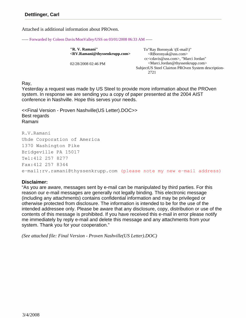
Figure 1 shows the local PROven® arrangement of one oven. Two spraying nozzles are installed in the gooseneck with the same functions as in the conventional ovens . They are responsible to cool down the passing raw gas and to keep the inside surface of the gooseneck wet to prevent deposits. The flow rate of the ammonia liquor through the nozzles remains constant and is not controlled.
At the downstream end of the gooseneck a tube made of stainless steel with slots cut into its end, called the “crown tube”, reaches down into the collecting main. The crown tube itself is surrounded by a cup, fixed to the roof of the collecting main, called the “FixCup”. It is made from stainless steel and is held by three screws enabling an adjustment of the position of the FixCup in all three dimensions. This is important to achieve an optimum relation between the positions of the crown tube and of the FixCup ensuring a homogeneous water level all around the crown tube. Inside the crown tube the overflow regulation device is installed. The entire unit is designed in stainless steel. At the bottom end of the overflow regulation device a plug is located which closes the bottom opening of the FixCup. Above the plug the siphon pipe is installed. At its top end it is closed by a lid, at its bottom end it is open to allow the flow of the ammonia liquor. Inside the siphon pipe the drain tube with slots is arranged, in which a passage piston is moving up and down. The piston is operated via a rod by the pneumatic cylinder directly located on top of the gooseneck. The water level in the Fixcup is
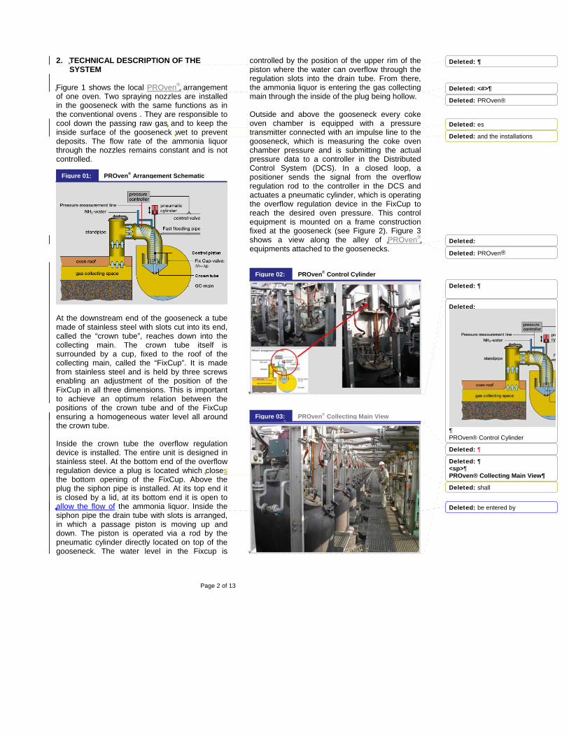
controlled by the position of the upper rim of the piston where the water can overflow through the regulation slots into the drain tube. From there, the ammonia liquor is entering the gas collecting main through the inside of the plug being hollow. Outside and above the gooseneck every coke oven chamber is equipped with a pressure transmitter connected with an impulse line to the gooseneck, which is measuring the coke oven chamber pressure and is submitting the actual pressure data to a controller in the Distributed Control System (DCS). In a closed loop, a positioner sends the signal from the overflow regulation rod to the controller in the DCS and actuates a pneumatic cylinder, which is operating the overflow regulation device in the FixCup to reach the desired oven pressure. This control equipment is mounted on a frame construction fixed at the gooseneck (see Figure 2). Figure 3 shows a view along the alley of PROven® equipments attached to the goosenecks.
PROven® Collecting Main ViewFigure 03:
PROven® Control CylinderFigure 02:
PROven® Arrangement Schematic Figure 01:
Deleted: 
Deleted: <#>
Deleted: PROven®
Deleted: es
Deleted: and the installations
Deleted:
Deleted: PROven®
Deleted: 
Deleted:
¶PROven® Control Cylinder
Deleted: 
Deleted: ¶<sp>¶PROven® Collecting Main View
Deleted: shall
Deleted: be entered by
Page 3 of 13
A fast flooding pipe is connected to the gooseneck which is able to quickly fill the FixCup with ammonia liquor in case that the oven is to be disconnected from the gas collecting main or in case the FixCup is to be flushed for cleaning. To avoid any incorrect operation, the opening of the standpipe lid is automatically done by a pneumatic cylinder. The operation of the standpipe lid is interlocked to ensure for example, that the standpipe lid can only be opened after the oven is disconnected from the gas collecting main.
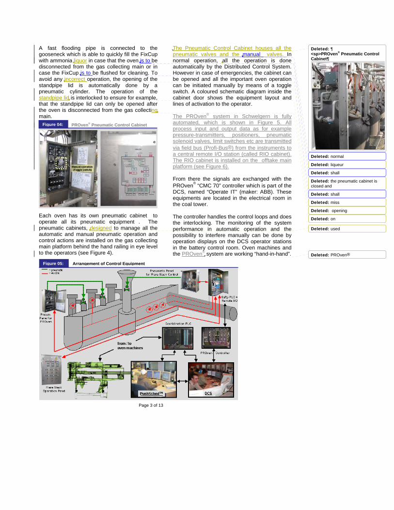
Each oven has its own pneumatic cabinet to operate all its pneumatic equipment . The pneumatic cabinets, designed to manage all the automatic and manual pneumatic operation and control actions are installed on the gas collecting main platform behind the hand railing in eye level to the operators (see Figure 4).
The Pneumatic Control Cabinet houses all the pneumatic valves and the manual valves. In normal operation, all the operation is done automatically by the Distributed Control System. However in case of emergencies, the cabinet can be opened and all the important oven operation can be initiated manually by means of a toggle switch. A coloured schematic diagram inside the cabinet door shows the equipment layout and lines of activation to the operator. The PROven® system in Schwelgern is fully automated, which is shown in Figure 5. All process input and output data as for example pressure-transmitters, positioners, pneumatic solenoid valves, limit switches etc are transmitted via field bus (Profi-Bus®) from the instruments to a central remote I/O station (called RIO cabinet). The RIO cabinet is installed on the offtake main platform (see Figure 6). From there the signals are exchanged with the PROven® “CMC 70” controller which is part of the DCS, named “Operate IT” (maker: ABB). These equipments are located in the electrical room in the coal tower. The controller handles the control loops and does the interlocking. The monitoring of the system performance in automatic operation and the possibility to interfere manually can be done by operation displays on the DCS operator stations in the battery control room. Oven machines and the PROven® system are working “hand-in-hand”.
PROven® Pneumatic Control Cabinet Figure 04:
Arrangement of Control Equipment Figure 05:
Deleted: ¶<sp>PROven® Pneumatic Control Cabinet
Deleted: normal
Deleted: liqueur
Deleted: shall
Deleted: the pneumatic cabinet is closed and
Deleted: shall
Deleted: miss
Deleted: opening
Deleted: on
Deleted: used
Deleted: PROven®
Page 4 of 13
The necessary pushing and charging actions are scheduled by an advanced scheduling program called PushSched® (maker: Uhde GmbH) taking the plant production and maintenance requirements into consideration. Besides normal production planning PushSched® can handle all types of special operation conditions (i.e. compensation of breakdowns or loss of production, schedule planning several days in advance, oven repairs, extension of coking times for individual ovens, etc.). Activated by a request from the machines, the scheduling program automatically calculates the pushing and charging time of each oven in advance and transmit this information via the “Coordination PLC” , called CO-PLC (maker: Siemens S7) to the machines for execution. The actual actions of the oven machines, the position of each machine, and special operation demands from the machines are collected by the CO-PLC and exchanged with the pushing and charging schedule program to automatically update and adopt the schedule. The DCS receives the same information from the “CO-PLC” and together with the PROven® controller coordinates the action of the machines with the action of the PROven® equipment at standpipes and goosenecks (for example disconnects the oven from the collecting main according to the schedule, if the minimum coking time has elapsed and the oven machines are ready). Since the gas collecting main is operated under suction, special care has to be taken to control the gas pressure in the collection main. Usually the flare stacks are operated automatically by the DCS as a security device to avoid over pressure in the gas off-take system in case of gas exhauster problems. However, the flare stacks can also be opened manually via a push-button control panel, located on the coal tower bench. Under all circumstances the accidental opening of the flare stacks and the intake of air via the flare stacks must be avoided, if the gas collecting main is still under suction. Therefore the gas collecting main pressure is measured by three independent instruments which are evaluated in a special high redundant PLC (maker: “HIMA”) which is also located on the walkway of the offtake main (see Figure 6).
This HIMA PLC is a government approved “Safety PLC”, designed to control process and operation conditions with special security needs. The gas pressure readings from the three instruments are checked against each other in this PLC and a “one out of three” signal selection takes place. The selected pressure reading is interlocked with the flare stack operation in this PLC, so that the flare stack can only be opened, if the gas collecting main pressure is showing positive pressure. Since the battery can be operated also under positive collecting main pressure (as in conventional systems), the flare stack must not open too early. It opens only in case of emergencies, which means the gas pressure must be safely above a set point of 15 mmWC. In this case the flare stacks are automatically opened by pneumatically operating the conventional water seal valves. The exhaust gas is ignited by an electric arc and diluted with steam to decrease the flame temperature as a protection against overheating the collecting main area and the battery top. The flare stacks are closing early, if the gas pressure drops under +3 mmWC, to avoid air to be sucked into the gas collecting main in case the main pressure continues to drop below zero. All these actions are controlled by the “Safty PLC”. The following sections will describe the main operation tasks of the PROven® system:
PROven® Instrumentation CabinetFigure 06:
Deleted: these
Deleted: <sp>
Deleted: ¶PROven® Instrumentation Cabinet
Deleted: PROven®
Deleted: on
Deleted: PROven®
Deleted: on
Deleted: ¶<sp>
Deleted: Arrangement of Control Equipment
Deleted: on
Deleted: on
Deleted: on
Deleted: PROven®
Deleted: ” )
Deleted: -
Page 5 of 13
Figure 7 shows the PROven®-system controlling the oven pressure during the coking process. As described above, every coke oven chamber is equipped with a pressure measurement device providing the actual pressure data of the coke oven to a controller in the DCS. Via a positioner the controller actuates a pneumatic cylinder which is operating the overflow regulation device in the FixCup via a rod. The overflow regulation device is adjusting the water level in the FixCup directly in relation to the pressure in the coke oven chamber. The FixCup in combination with the crown tube is working like a butterfly-valve which is opening more or less by the adjusted water level within the FixCup. The gas collecting main is operated under suction of approximately –20 to 30 mm WC (control condition), so that the controlled water level in the FixCup is capable to keep a constant pressure in the oven chamber as long as raw gas generation takes place.
Figure 8 shows the operational condition if the oven chamber is disconnected from the gas collecting main to prepare the oven for pushing. In this case the plug at the bottom outlet of the FixCup as well as the passage piston in the drain tube of the overflow regulation device are in the closed position. The ammonia liquor level is raised up to the maximum level which is the top edge of the FixCup. To shorten the time for charging the FixCup with ammonia liquor, an additional separate fast flooding pipe is installed offering a larger flow rate of ammonia liquor than the continuously running spraying nozzles. To maintain the operational safety, the fast flooding pipe stays open as long as the oven is disconnected.
Figure 9 shows the operational condition if the oven chamber is reconnected to the gas collecting main during the charging process with maximum amount of suction needed for disposing the charging gas. To achieve this, the pneumatic cylinder on the top of the gooseneck has lifted the entire overflow regulation device as well as the plug, which is connected to it, into its upper position, to open the bottom outlet of the FixCup. The ammonia liquor utilized from the spraying nozzles to cool the raw gases is directly discharged into the gas collecting main and the crown tube is fully open to the gas collection main. There is no ammonia liquor in the FixCup anymore which can create a pressure loss between coke oven chamber and gas collecting main. The suction in the gas collecting main of approximately -30 mm WC (charging condition) directly acts on the charging gases in the coke oven chamber to evacuate them into the gas collecting main.
PROven® In Control Position Figure 07:
PROven® Oven Disconnected Figure 08:
PROven® in Charging PositionFigure 09:Deleted: PROven®
Figure 10 shows the complete installation. Each gooseneck is equipped with the same combination of a Fixcup, a crown tube and the associated control devices, which work like “variable water valves” in which the water level increases or decreases according to the gas pressure in the oven. The depth of the water in the FixCup determines the available flow area through which the raw gas can flow from the gooseneck into the collecting main. Since each oven on the battery is in a different coking condition, thus producing a different amount of raw gas, each Fixcup has to be controlled differently according to the gas pressure within the oven. The system can be compared to butterfly valves which are controlled by actuators to maintain constant pressure in each oven which are cascaded on top of the conventional main butterfly control valve in the off-take main. The uncontrolled off-take main pressure of minus 110 mm WC is throttled at the conventional butterfly control valve down to a pressure of minus 20-30 mmWC in the gas collecting main. The collecting main pressure of minus 20-30 mmWC is again throttled by the “FixCup-Water-butterfly” down to a pressure of plus 6 mmWC in each oven. To maintain this pressure for the different raw gas production, each “FixCup-Water-butterfly” is in a different setting. As shown in figure 10, ovens freshly charged are producing a lot of raw gas, therefore the “butterfly” is in “full open” position. Ovens, which are fully coked, do not produce any more raw gas, therefore the “butterfly” is nearly “fully closed”. The PROven®-System is able to manage all necessary actions of a complete coking cycle. It starts with closing the stand pipe lid and connecting the coke oven to the gas collecting main for charging the coke oven. It is followed by controlling the oven pressure depending on the actual amount of coke oven raw gas generated during the coking period. And
it is finished with disconnecting the coke oven from the gas collecting main followed by opening the stand pipe lid to prepare for pushing. To further clarify the differences between the PROven®-System against a conventional system, the theoretical oven pressure curves of one oven over a complete coking cycle are shown in Figure 11.
In conventionally operated coke oven batteries, the pressure inside of each oven chamber has its peak during and immediately after charging, as the highest amount of raw gas is generated in the early stages of the carbonization time (Curve 1). Towards the end of the carbonization process, the generation of raw gas is decreasing. Therefore, the pressure in the oven chamber is gradually approaching its minimum when the coal is fully carbonized and the coke is ready for pushing. In contrast to this, the gas collecting main which connects the individual ovens is operated at a constant set pressure (Curve 2), regulated by a control valve in the suction main, irrespective of the progress of carbonization or of the amount of raw gas generation in any single oven. Therefore, the actual adjustment of the gas collecting main pressure at conventional batteries always remains a compromise, never achieving perfect pressure conditions for any one of the ovens. In the PROven® System, for each chamber the set point of the pressure will be adjusted to the optimum. During and after coal charging the pressure in the standpipe is set very low in order to facilitate the discharge of the raw gas to the gas collecting main. With advance of carbonization time and decrease in raw gas
Collecting Main Control with PROven® Figure 10:
Gas Pressure (Oven Chamber & Collecting Main) Figure 11:
Deleted: PROven® Arrangement Schematic
Deleted: ¶Figure 10: Collecting Main with PROven® Installation
Deleted: PROven®
Deleted: ¶Figure 11: Gas Pressure in Oven Chamber and in the Collecting Main
Deleted: on
Deleted: on
Deleted: PROven®
Deleted: PROven®
Deleted: was to be
Page 7 of 13
generation, the pressure in the standpipe is increased step by step (Curve 3). As a result, the pressure measured in the oven chamber at the foot of the oven doors will be maintained at a constantly low level of pressure during the whole carbonization process (Curve 4). The impact on the emission control aspect of the PROven® System is evident from this Figure. So fare we discussed the theory behind the PROven® System. The following section will show how the system was adjusted and is operating in real life. 3. OPERATING EXPERIENCES
3.1 Commissioning The Schwelgern coke oven batteries went into operation in March and May 2003. When charging the first oven of each battery, the PROven® system was already in full operation. With this system it was possible to charge even the first oven without opening the standpipe, thus improving the environmental protection from the very initial stages of operation. In the first weeks of operation, neither the exhauster controller nor the gas collecting main controller was optimized and the pressure set points on the PROven® controller was set to only one constant value.
Figure 12 shows the uncontrolled off-take exhauster pressure, the controlled collecting main pressure, the signal from the passage piston positioner representing the "butterfly opening" of the PROven® system and the controlled oven pressure for one oven over one coking cycle. The heavily fluctuating off-take main suction (Curve 1) is throttled by the conventional collecting main control valve (Askania valve) from –110mmWC down to minus 30mmWC (Curve 2). This central control valve has dampened the fluctuations significantly, however sharp pressure peaks are still visible. The opening of the PROven® butterfly (Curve 3) decreases from “full open” (during charging) to “75% open” (after charging) down to “30% open” (shortly before pushing). The resulting oven pressure (Curve 4) remains constant (+6 mm WC) over the full coking cycle and the pressure fluctuations inside the oven are reduced to a minimum. The advantage is clear: The PROven® control "butterfly" on each standpipe works like a damper against pressure peaks in the gas collecting main, which are common during the charging of adjacent ovens or due to suction fluctuations of the exhauster on the by-product side. This is one of the main reasons for the reduction of raw gas emissions during the coking cycle with the PROven® System. Raw Gas Pressure (“Offtake” System) Figure 12:
Formatted: Bullets and Numbering
Formatted: Bullets and Numbering
Deleted: was to be
Deleted: ¶Figure 12: Raw Gas Pressure in the “Take-OffOfftake” System
Deleted: PROven®
Deleted: PROven®
Deleted: PROven®
Deleted: much said to the theory
Deleted: ,
Deleted: PROven®
Deleted: live.
Deleted: ¶¶3.
Deleted: ON
Deleted: 
Deleted: 3.1
Deleted: closed
Deleted: batteries
Deleted: 2003
Deleted: PROven®
Deleted: PROven®
Deleted: PROven®
Deleted: PROven®
Page 8 of 13
Furthermore the positioner signal, which is analogue to the water level within the FixCup and inverse analogue to the amount of the momentary raw gas production gives a qualitative information about the raw gas production over the coking time. The maximum production of raw gas can be seen approx. 2.5 h after charging, when the water in the FixCup is on its lowest level (PROven® „Butterfly“ 75 % open). A relatively constant raw gas generation for approx. 17 h can be seen in the middle of the coking cycle and a linear decreasing of raw gas generation is starting approx. 9 h before the end of the coking cycle after the heavy hydrocarbons have been expulsed and the tar seam is closing.
3.2 Normal Operation Five months later, the battery was commissioned near to full production (26.5 h coking time ) and most of the adjustment had been done. The exhauster control (Curve1) and the conventional collecting main control (Curve 3) shown in Figure 13 are much better now and the PROven® control has been improved by incorporating five pressure set points into the control to drive the oven pressure during the coking cycle according to the raw gas development in the coke mass.
The five oven pressure setpoints seen in curve 4 of Figure 13 are increased in steps from approx. +2 mmWC (after charging) to +13 mmWC (short before pushing). These pressure set points have been selected without knowing exactly how the pressure at the door near sole flue level are. But you could virtually see the results at the doors. There was no visible door emission anymore. To determine the correct set point and to find the best setting, this means avoiding suction behind the doors but still no emission, a survey was planned. The results of this survey are discussed later in this paper.
3.3 Monitoring of the Coking Process Some process signals of the PROven® system can be used to continuously monitor the coking process for each oven. Figure 14 shows the differential pressure and the positioner signal curve as a control indicator for the coking process.
Raw Gas Pressure (after final adjustment) Figure 13:
Formatted: Bullets and Numbering
Formatted: Bullets and Numbering
Deleted: ¶Figure 13: Raw Gas Pressure in the “Take-Off” System (After Final Adjustment)
Deleted: PROven®
Deleted: 3.3
Deleted: 3.2
Deleted: PROven®
Deleted: PROven®
Page 9 of 13
The differential pressure shows the maximum production of raw gas approx. 2.0 h after charging, when the water level in the FixCup is on its lowest position (PROven® „Butterfly“ 90 % open). The raw gas production steadily and quickly decreases for another 4 hours, then a slower more linear decrease takes place in the middle of the coking cycle until for another 12 to 14 hours. After that a strong linear decreasing of raw gas generation is starting approx. 3.5 h before the end of the coking cycle after the heavy hydrocarbons where mostly driven off and the tar seam has been closed. The positioner is closing more and more according to the decrease of raw gas until the raw gas generation has dropped under an uncritical value ( approx. 50 % FixCup “closed” ) which means the oven is sufficiently carbonized and can be released for pushing by the DCS (earliest half an hour before the schedule). Many coke plants are using temperature measurements on the standpipe or gooseneck just to get the same results. The Schwelgern coke plant does not have such a system, so a typical raw gas temperature curve from another coke plant was selected, adjusted to the given coking time and placed into the graph. As it can easily be seen, the steep temperature drop, used by others to identify the end of the coking goes along with the decrease of the differential pressure as well as with the increase of the
positioner signal. This is because all these values are the indirect indicators for the same phenomena , which is the end of raw gas production at the end of the coking cycle. It can be said that the measurements needed to make the PROven® system work can be used to identify the coking end time without the additional investment for a raw gas temperature measuring system.
3.4 Monitoring and Maintaining the System The PROven® system works fully automatically and is monitored via operator stations in the battery control room (see Figure 5). The main operation display shows standpipe/gooseneck representations for all ovens of one gas collecting main section with all their important process data on one screen (see Figure 15).
Positioner signal curve as a control indicator for the coking processFigure 14:
Formatted: Bullets and Numbering
Deleted: 
Deleted: Figure 14: Positioner Signal Curve as a Control Indicator for the Coking Process ¶¶
Deleted: PROven®
Deleted: a
Deleted: PROven®
Deleted: 3.4 Monitoring and Maintaining the System¶¶
Deleted: PROven®
Deleted: on
Deleted: 
Page 10 of 13
In this example, all ovens are in automatic control. Oven no. 79 is already disconnected, the fast flooding valve is open (“red valve”), the standpipe lid is open (“AUF”=green) and the oven is ready for pushing, while oven no. 74 is connected to the gas collecting main and is under charging. The overlaid display shows the control accuracy of each PROven® controller represented by a "magic eye". Each green bar represents the difference between the nominal value of the oven pressure and the actual value. As smaller the green bar appears on the screen as more the controller is "tuned in", meaning closer the control is to the target. Oven no. 79 is ready for pushing and the control is off-line. Oven 74 is under charging with the FixCup valve full open and with a maximum suction of minus 2,72 mbar (=-27,2 mmWC ) on the oven. The operator can use the displays to switch each single PROven® controller into manual mode and to manipulate all operation sequences interactively from the screen (disconnect, open the standpipe, open the fast flooding valve, etc). The operation in manual mode is usually only be done to execute cleaning activities on standpipes and goosenecks or for other maintenance and repair requirements. The cleaning of standpipes and goosenecks is more or less the
same as with conventionally equipped batteries, but must not be done as frequently due to less “carry-over” coal deposits. On the other hand, the impulse line for the pressure transmitter (which is not purged with nitrogen in the Schwelgern plant) needs to be cleaned in regular intervals of approx. once per month. To further monitor the system, the oxygen level in the raw gas is continuously measured and checked in the gas line before the electrostatic precipitator. An oxygen level of 0,10 to 0,15 Vol.% is normal with peaks up to 0,5 to 0,8 %. This is the air which is sucked into the collecting main during charging and levelling. If the oxygen level goes above 1%, an alarm on the DCS is created, to check whether the FixCup water seals of the disconnected ovens are operating properly. If the oxygen level goes above 1,5 % oxygen, the electrostatic precipitator are shut down. Additionally the operation of the automatic pushing and charging schedule program “PushSched®” can be monitored on an operator station in the battery control room (see figure 16). The menu systems allows the operator to monitor the execution of the schedule, make adjustments to the schedule, place a strategy to make up for production, take ovens out for repair, put
DCS Control Screen for PROven® Figure 15:
Deleted: 
Deleted: Figure 15: DCS control screen for PROven® 
Deleted: PROven®
Deleted: PROven®
Page 11 of 13
individual ovens on longer coking times, etc. Figure 16 in example shows the schedule of oven series no. 4 of the 5/2 schedule in Schwelgern, with all operation times, oven operation data and the elapsed coking times as colored bar graphs.
3.5 System Improvements To have a good control, the slots of the crown
tube have been made narrower in the upper part of the tube (the slot-width goes from 25 mm in one step down to 5 mm in the upper part of the crown tube). This was done because at the end of the carbonisation when the gas generation is low, the FixCup water level should open or close a smaller gas free space in the water valve. Therefore, the stroke movement initiated by the controller must be smaller if the water level is in this upper, narrower section to avoid over controlling. Reducing the stroke distance on the passage piston rod (= water level change in the FixCup) will result in a smaller change in the gas free space, thus having a more sensitive control. By splitting the control range into an area with “wide” stroke movements (using different control parameters), the system is able to control the oven chamber pressure of an oven in a large range of volumetric flow rates of the generated raw gas with improved accuracy. Between the maximum generated raw gas peak of approximately 5800 m3/h and less than 100 m3/h at the end of the carbonisation, a good and sensitive control can be maintained. To further improve the behaviour of the PROven® control and to completely get rid off any emission, the collecting main pressure is reduced from -20 mmWC to – 30 mmWC before the first oven of the respective gas collecting main section is
about to be charged (see figure 13). After the last oven of the gas collecting main section is charged, the set point of the gas collecting main is set back to – 20 mmWC. Because of the 5/2-pushing schedule there are five reductions of the gas collecting main pressure to – 30 mmWC during one coking cycle of an oven. Figure 13 shows these five reductions. These reductions are now standard operation practice and are executed automatically by the DCS. The gas collecting main controllers were further optimized by adjusting the gate valves in the connecting (bypass) pipes between the individual gas collecting main sections (three sections per battery each). The adjustment of these gate valves was necessary to reduce the dependency between the gas collecting main sections thus improving the controlling by partly closing these valves. But they cannot be closed completely because there must be a sufficient opening to divert a part of the volume peak of a charging process into the neighbouring gas collecting main section(s) to reduce the pressure peak.
3.6 Measurements of Poly-Aromatic Hydrocarbons (PAH)
To evaluate the environmental advantages of the PROven® system already in the earlier stages of the PROven® development , measurements of the content of poly-aromatic hydrocarbons (PAH) in the air were taken at battery 6b of the coke plant August Thyssen before and after the installation of the PROven® system (see Figure 17).
The measurements were taken on the pusher side and on the coke side of the battery, in the
Deleted: <#>To improve the control, the slots of the crown tube have been made narrower in the upper part of the tube (5 mm as against 25 mm at the lower part of the crown tube). This was done because at the end of the coking cycle when the gas generation is low, the Fix Cup-water level should open or close a smaller gas free space in the water valve. The same stroke distance on the passage piston rod ( = water level change in the FixCup) will result in a smaller change in the gas free space, thus having a more sensitive control. With this modification, the system is able to control the oven chamber pressure of an oven in a large range of volumetric flow rates of the generated raw gas. Between the maximum generated raw gas peak of approx. 5800 m³/h and less than 100 m³/h at the end of the coking time with a good and sensitive control can be maintained.
Deleted: ¶3.6
Deleted: PROven®
Deleted: PROven®
Deleted: PROven®
Deleted: 
Deleted: PROven®
Deleted: mmWC before
Deleted: 
Deleted: Figure17: Measured PAH- Emissions Without and With PROven®¶ 
Page 12 of 13
periods 0 to 2 hours and 2 to 5 hours after coal charging by an independent research institute, the DMT (Deutsche Montan Technologie / Germany). The result, which is displayed in Figure 17, shows a reduction of the PAH-emissions of approximately 70% compared with conventional ovens.
3.7 Pressure Behind the Oven Doors To further investigate the influence of the pressure in the oven through the PROven® system a survey was planned. For this, an oven door was prepared with several holes drilled into the door in different positions (see Figure 18). The pressure behind the door was measured in three different heights (P1-P3) in the channel behind the plug. This channel (marked as “P” in Figure 18) goes from the bottom of the door to the top and is designed to allow a free gas flow behind the door, thus avoiding a pressure build-up behind the door which may create leakage and emission. The survey was done during one complete coking cycle, measuring the gas collecting main pressure, the controlled oven pressure adjusted by the PROven® system and the pressure in the channel behind the door in three different positions (see Figure 18).
The oven pressure can be set to every value needed, to optimize the oven conditions and the tightness of the doors. Therefore the oven pressure in this case was held at 10 mmWC for 17.5 hours, then it was raised to 12 mmWC. As can be seen the average pressure behind the door is decreasing from top to bottom. At level P1, the pressure follows the controlled oven pressure curve but already on a lower level of approx. 3 to 5 mmWC, the pressure at P2 is straight around +/- 0 mmWC and at P3 it is fluctuating around zero and goes below zero at the end of the coking cycle. It is anticipated that at the end of the coking cycle, the pressure behind the doors should be around +/- 0 mmWC, so that sucking of air into the oven could be avoided. But a little bit of suction as shown near the bottom of the door will probably cause no harm, if the door is doing its service that means keeping the oven sealed. It is also to be determined, if the unwanted suction measured at the bottom of the door is partly due to the chimney effect within the pressure release channel. As easily seen in these curves, the oven pressure, controlled by the PROven® system, can be gradually tuned according to the development of raw gas so that at the beginning of the coking
Pressure Behind the Oven Door (in three levels)Figure 18:
Deleted: ¶3.7
Deleted: PROven®
Deleted: PROven®
Deleted: PROven®
Deleted: 
Page 13 of 13
cycle the pressure behind the door is maintained just low enough to prevent emission, and at the end of the coking cycle is high enough to prevent suction behind the door. Different coke plants with different oven dimensions and different door designs would probably require different settings from the ones determined by the shown survey from the Schwelgern coke plant. 4. BENEFITS and CONCLUSION Ever since, the PROven® system is operating to the full satisfaction of the plant operators, reducing the emissions at the batteries to a degree never experienced before. Charging of the ovens is virtually emission-free and there are no visible emissions at the oven doors, standpipe lids and charging holes. The charging operation takes place without any system of high pressure water or steam injection, the produced raw gas is simply sucked into the gas collecting main with the suction adjusted in the main as needed. Therefore all other special equipment to prevent the emission of charging gas, as in example double collection mains, mini-standpipes or jumper pipes are obsolete. Due to the individual control of the oven pressure, no excessive suction is created in goosenecks and standpipes which results in a tremendous reduction of carry over of coal during charging and therefore improving of the tar quality.
The system works at the Schwelgern coking plant from the first charging of the very first oven up to now very successfully. It was enthusiastically accepted by the operators without complaint and has been continuously optimized ever since. The test installation done at battery 6b of the coke plant August Thyssen has proven, that it is possible and feasible to install a PROven® system also into existing plants and that this measure can reduce the overall emissions significantly. It is obvious, that with the PROven® system it becomes possible to run these older batteries emission-free, even if the chamber walls are not sealed against the heating walls anymore. This could be done by adjusting the oven pressure in such a way that raw gas will not leak into the heating flue and hot waste gas will not leak into the oven chamber. This advantage has to be balanced against possible damages due to overheating of doors and end-flue brickwork by air, which may be sucked into the oven. But even if it cannot be accepted as a standard operation procedure, this method can be always used for a short period of time (maybe 2 weeks) to avoid immediate temporary repair action and to have time for planning the final repair. Long time experiences with this type of operation are still to be gained.


![[Additional Information] HANDs! Project_0](https://static.documents.pub/doc/80x56/55cf8673550346484b97bad3/additional-information-hands-project0.jpg)

