20
A L T R A M O T I O N Sure-Flex Plus ® Elastomeric Couplings (Metric)
A L T R A M O T I O N
Sure-Flex Plus®
Elastomeric Couplings (Metric)
The Brands of Altra Motion
Couplings
Ameridriveswww.ameridrives.com
Bibby Turbo� ex www.bibbyturbo� ex.com
Guardian Couplingswww.guardiancouplings.com
Hucowww.huco.com
Lami� ex Couplingswww.lami� excouplings.com
Stromag www.stromag.com
TB Wood’swww.tbwoods.com
Linear Systems
Thomsonwww.thomsonlinear.com
Geared Cam Limit Switches
Stromagwww.stromag.com
Engineered Bearing Assemblies
Kilianwww.kilianbearings.com
Electric Clutches & Brakes
Matrixwww.matrix-international.com
Stromagwww.stromag.com
Warner Electricwww.warnerelectric.com
Deltranwww.thomsonlinear.com
Belted DrivesTB Wood’s www.tbwoods.com
Heavy Duty Clutches & Brakes
Twi� exwww.twi� ex.com
Stromagwww.stromag.com
Svendborg Brakeswww.svendborg-brakes.com
Wichita Clutchwww.wichitaclutch.com
Gearing & Specialty Components
Bauer Gear Motorwww.bauergears.com
Boston Gearwww.bostongear.com
Delevanwww.delevan.com
Delroyd Worm Gearwww.delroyd.com
Nuttall Gearwww.nuttallgear.com
Engine Braking Systems
Jacobs Vehicle Systemswww.jacobsvehiclesystems.com
Precision Motors & Automation
Kollmorgenwww.kollmorgen.com
Miniature Motors
Portescapwww.portescap.com
Overrunning Clutches
Formsprag Clutchwww.formsprag.com
Marland Clutchwww.marland.com
Stieberwww.stieberclutch.com
TB Wood’s Facilities
North America
USA
440 North Fifth AvenueChambersburg, PA 17201 - USA888-829-6637 * 717-264-7161
Belted Drives and Elastomeric Couplings
Customer Service1-888-829-6637 (Press #5)
For Application Support1-888-829-6637 (Press #7)
2000 Clovis Barker RoadSan Marcos, TX 78666 - USA1-888-449-9439
General Purpose Disc Couplings
Customer Service1-888-449-9439
4970 Joule StReno, NV 89502 - USA775-857-1800
Canada
9779 45 Ave NWEdmonton, AB T6E 5V8 - Canada+1 780-439-7979
6305 Danville RoadMississauga, ON L5T 2H7 - Canada1-800-829-6631
1073 Rue BéginSaint-Laurent, QC H4R 1V8 - Canada+1 514-332-4812
Mexico
Comisión Federal de Electricidad 850, Industrial San Luis, San Luis, S.L.P., 78395 - Mexico+52 444 137 1500
Europe
Merchant Drive, HertfordHertfordshire SG13 7BL - England+44(0)1992 501900
Elastomeric Couplings
Neither the accuracy nor completeness of the information contained in this publication is guaranteed by the company and may be subject to change in its sole discretion. The operating and performance characteristics of these products may vary depending on the application, installation, operating conditions and environmental factors. The company’s terms and conditions of sale can be viewed at http://www.altramotion.com/terms-and-conditions/sales-terms-and-conditions. These terms and conditions apply to any person who may buy, acquire or use a product referred to herein, including any person who buys from a licensed distributor of these branded products.
©2019 by TB Wood’s LLC. All rights reserved. All trademarks in this publication are the sole and exclusive property of TB Wood’s LLC or one of its af� liated companies.
2 www.tbwoods.com P-1957-TBW-A4 12/19
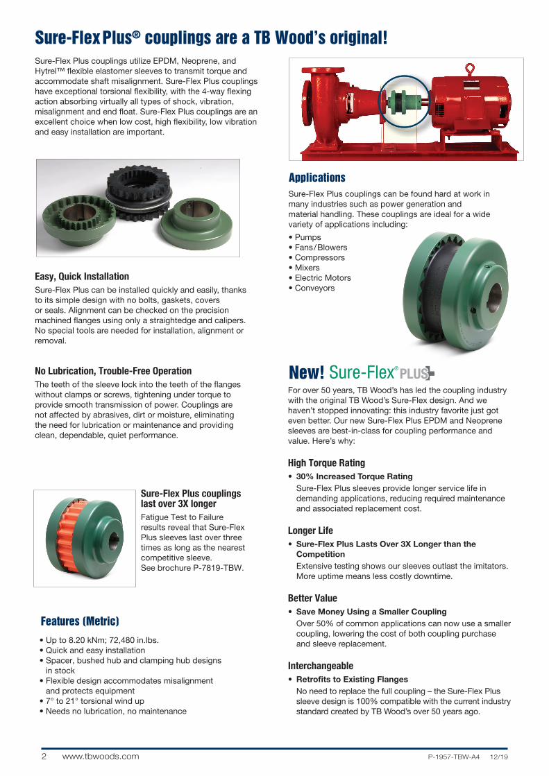
Sure-Flex Plus couplings utilize EPDM, Neoprene, and Hytrel™ flexible elastomer sleeves to transmit torque and accommodate shaft misalignment. Sure-Flex Plus couplings have exceptional torsional flexibility, with the 4-way flexing action absorbing virtually all types of shock, vibration, misalignment and end float. Sure-Flex Plus couplings are an excellent choice when low cost, high flexibility, low vibration and easy installation are important.
Sure-Flex Plus couplings last over 3X longerFatigue Test to Failure results reveal that Sure-Flex Plus sleeves last over three times as long as the nearest competitive sleeve. See brochure P-7819-TBW.
Sure-Flex Plus® couplings are a TB Wood’s original!
Sure-Flex Plus couplings can be found hard at work in many industries such as power generation and material handling. These couplings are ideal for a wide variety of applications including:
• Pumps• Fans/Blowers• Compressors• Mixers• Electric Motors• Conveyors
Applications
• Up to 8.20 kNm; 72,480 in.lbs.• Quick and easy installation • Spacer, bushed hub and clamping hub designs
in stock• Flexible design accommodates misalignment
and protects equipment• 7° to 21° torsional wind up• Needs no lubrication, no maintenance
Features (Metric)
Need hi-res color file
Easy, Quick InstallationSure-Flex Plus can be installed quickly and easily, thanks to its simple design with no bolts, gaskets, covers or seals. Alignment can be checked on the precision machined flanges using only a straightedge and calipers. No special tools are needed for installation, alignment or removal.
No Lubrication, Trouble-Free OperationThe teeth of the sleeve lock into the teeth of the flanges without clamps or screws, tightening under torque to provide smooth transmission of power. Couplings are not affected by abrasives, dirt or moisture, eliminating the need for lubrication or maintenance and providing clean, dependable, quiet performance.
For over 50 years, TB Wood’s has led the coupling industry with the original TB Wood’s Sure-Flex design. And we haven’t stopped innovating: this industry favorite just got even better. Our new Sure-Flex Plus EPDM and Neoprene sleeves are best-in-class for coupling performance and value. Here’s why:
High Torque Rating• 30% Increased Torque Rating
Sure-Flex Plus sleeves provide longer service life in demanding applications, reducing required maintenance and associated replacement cost.
Longer Life• Sure-Flex Plus Lasts Over 3X Longer than the
CompetitionExtensive testing shows our sleeves outlast the imitators. More uptime means less costly downtime.
Better Value• Save Money Using a Smaller Coupling
Over 50% of common applications can now use a smaller coupling, lowering the cost of both coupling purchase and sleeve replacement.
Interchangeable• Retrofits to Existing Flanges
No need to replace the full coupling – the Sure-Flex Plus sleeve design is 100% compatible with the current industry standard created by TB Wood’s over 50 years ago.
New!
3P-1957-TBW-A4 12/19 www.tbwoods.com
Sure-Flex Plus Selection Guide
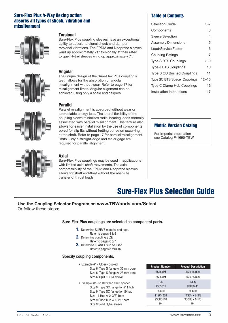
Sure-Flex Plus 4-Way flexing action absorbs all types of shock, vibration and misalignment
Table of Contents
AxialSure-Flex Plus couplings may be used in applications with limited axial shaft movements. The axial compressibility of the EPDM and Neoprene sleeves allows for shaft end-float without the absolute transfer of thrust loads.
ParallelParallel misalignment is absorbed without wear or appreciable energy loss. The lateral flexibility of the coupling sleeve minimizes radial bearing loads normally asso ciated with parallel misalignment. This feature also allows for easier installation by the use of components bored for slip fits without fretting corrosion occurring at the shaft. Refer to page 17 for parallel misalignment limits. Only a straight-edge and feeler gage are required for parallel alignment.
AngularThe unique design of the Sure-Flex Plus coupling’s teeth allows for the absorption of angular misalignment without wear. Refer to page 17 for misalignment limits. Angular alignment can be achieved using only a scale and calipers.
TorsionalSure-Flex Plus coupling sleeves have an exceptional ability to absorb torsional shock and dampen torsional vibrations. The EPDM and Neoprene sleeves wind up approxi mately 21° torsionally at their rated torque. Hytrel sleeves wind up approximately 7°.
Selection Guide 3-7
Components 3
Sleeve Selection 4
Assembly Dimensions 5
Load/Service Factor 6
Coupling Ratings 7
Type S BTS Couplings 8-9
Type J BTS Couplings 10
Type B QD Bushed Couplings 11
Type SC BTS Spacer Couplings 12–15
Type C Clamp Hub Couplings 16
Installation Instructions 17
Sure-Flex Plus couplings are selected as component parts.
1. Determine SLEEVE material and type. Refer to pages 4 & 5 2. Determine coupling SIZE. Refer to pages 6 & 7 3. Determine FLANGES to be used. Refer to pages 8 thru 16
Specify coupling components.
• Example #1 - Close coupled Size 6, Type S flange w 35 mm bore Size 6, Type S flange w 25 mm bore Size 6, Split EPDM sleeve
• Example #2 - 5” Between shaft spacer Size 9, Type SC flange for #11 hub Size 9, Type SC flange for #9 hub Size 11 Hub w 2-3/8” bore Size 9 Short hub w 1-1/8” bore Size 9 Solid Hytrel sleeve
Metric Version Catalog
For Imperial information see Catalog P-1690-TBW
Product Number Product Description
6S35MM 6S x 35 mm
6S25MM 6S x 25 mm
6JS9SC5011
6JES9SC50-11
9SC50 9SC50
11SCH238 11SCH x 2-3/89SCHS118
9H9SCHS x 1-1/8
9H
Use the Coupling Selector Program on www.TBWoods.com/Select Or follow these steps:
4 www.tbwoods.com P-1957-TBW-A4 12/19
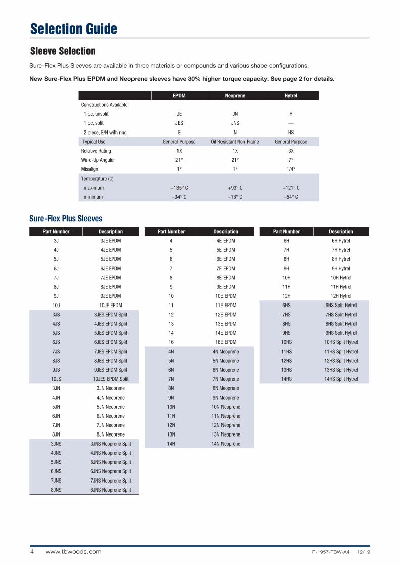
Selection GuideSleeve SelectionSure-Flex Plus Sleeves are available in three materials or compounds and various shape configurations.
New Sure-Flex Plus EPDM and Neoprene sleeves have 30% higher torque capacity. See page 2 for details.
Sure-Flex Plus Sleeves
Part Number Description
3J 3JE EPDM
4J 4JE EPDM
5J 5JE EPDM
6J 6JE EPDM
7J 7JE EPDM
8J 8JE EPDM
9J 9JE EPDM
10J 10JE EPDM
3JS 3JES EPDM Split
4JS 4JES EPDM Split
5JS 5JES EPDM Split
6JS 6JES EPDM Split
7JS 7JES EPDM Split
8JS 8JES EPDM Split
9JS 9JES EPDM Split
10JS 10JES EPDM Split
3JN 3JN Neoprene
4JN 4JN Neoprene
5JN 5JN Neoprene
6JN 6JN Neoprene
7JN 7JN Neoprene
8JN 8JN Neoprene
3JNS 3JNS Neoprene Split
4JNS 4JNS Neoprene Split
5JNS 5JNS Neoprene Split
6JNS 6JNS Neoprene Split
7JNS 7JNS Neoprene Split
8JNS 8JNS Neoprene Split
Part Number Description
4 4E EPDM
5 5E EPDM
6 6E EPDM
7 7E EPDM
8 8E EPDM
9 9E EPDM
10 10E EPDM
11 11E EPDM
12 12E EPDM
13 13E EPDM
14 14E EPDM
16 16E EPDM
4N 4N Neoprene
5N 5N Neoprene
6N 6N Neoprene
7N 7N Neoprene
8N 8N Neoprene
9N 9N Neoprene
10N 10N Neoprene
11N 11N Neoprene
12N 12N Neoprene
13N 13N Neoprene
14N 14N Neoprene
Part Number Description
6H 6H Hytrel
7H 7H Hytrel
8H 8H Hytrel
9H 9H Hytrel
10H 10H Hytrel
11H 11H Hytrel
12H 12H Hytrel
6HS 6HS Split Hytrel
7HS 7HS Split Hytrel
8HS 8HS Split Hytrel
9HS 9HS Split Hytrel
10HS 10HS Split Hytrel
11HS 11HS Split Hytrel
12HS 12HS Split Hytrel
13HS 13HS Split Hytrel
14HS 14HS Split Hytrel
EPDM Neoprene Hytrel
Constructions Available
1 pc, unsplit JE JN H
1 pc, split JES JNS —
2 piece, E/N with ring E N HS
Typical Use General Purpose Oil Resistant Non-Flame General Purpose
Relative Rating 1X 1X 3X
Wind-Up Angular 21° 21° 7°
Misalign 1° 1° 1/4°
Temperature (C)
maximum +135° C +93° C +121° C
minimum –34° C –18° C –54° C
5P-1957-TBW-A4 12/19 www.tbwoods.com
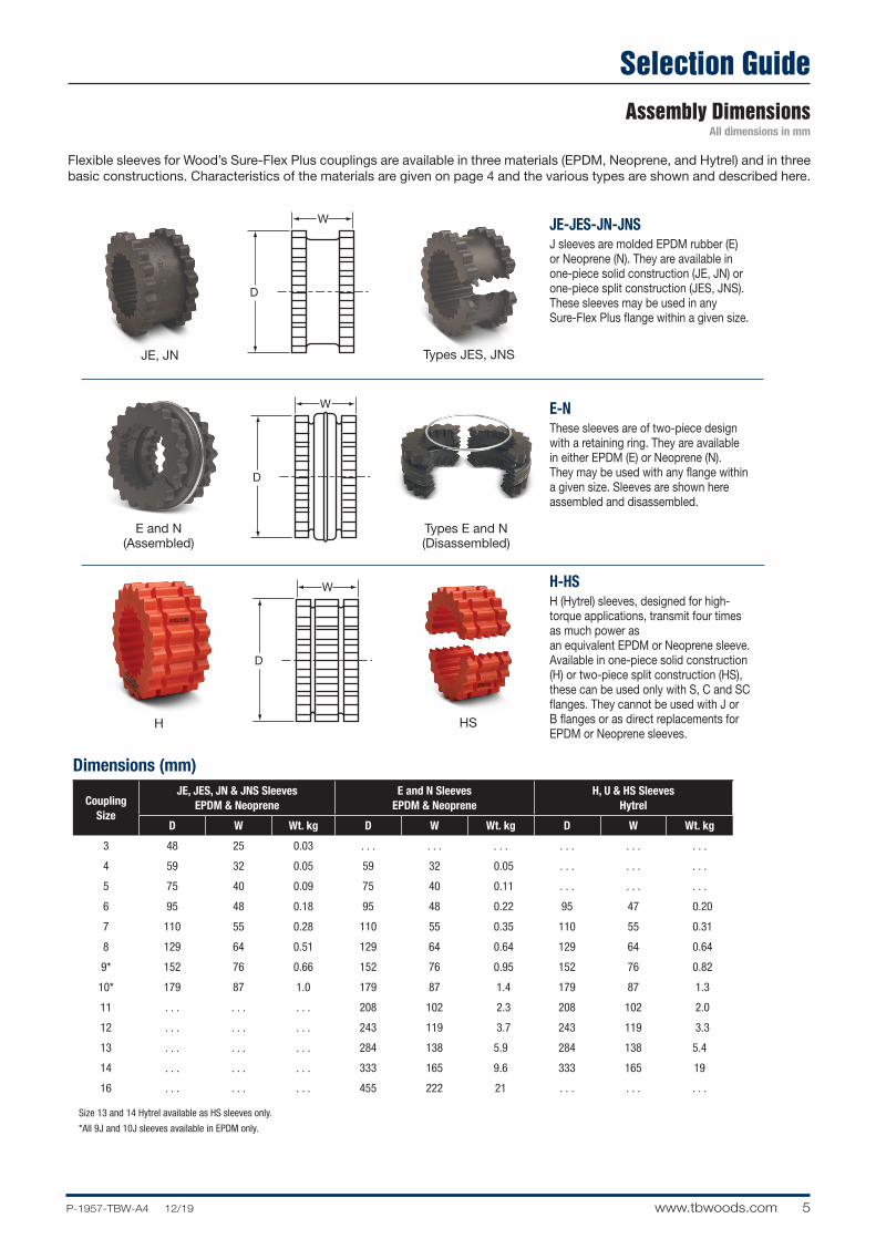
Selection GuideAssembly Dimensions
All dimensions in mm
Flexible sleeves for Wood’s Sure-Flex Plus couplings are available in three materials (EPDM, Neoprene, and Hytrel) and in three basic constructions. Characteristics of the materials are given on page 4 and the various types are shown and described here.
Dimensions (mm)
JE-JES-JN-JNSJ sleeves are molded EPDM rubber (E) or Neoprene (N). They are available in one-piece solid construction (JE, JN) or one-piece split construction (JES, JNS). These sleeves may be used in any Sure-Flex Plus flange within a given size.
E-NThese sleeves are of two-piece design with a retaining ring. They are available in either EPDM (E) or Neoprene (N). They may be used with any flange within a given size. Sleeves are shown here assembled and disassembled.
H-HSH (Hytrel) sleeves, designed for high-torque applications, transmit four times as much power as an equivalent EPDM or Neoprene sleeve. Available in one-piece solid construction (H) or two-piece split construction (HS), these can be used only with S, C and SC flanges. They cannot be used with J or B flanges or as direct replacements for EPDM or Neoprene sleeves.
JE, JN
E and N(Assembled)
H HS
Types E and N(Disassembled)
Types JES, JNS
Coupling Size
JE, JES, JN & JNS Sleeves EPDM & Neoprene
E and N Sleeves EPDM & Neoprene
H, U & HS Sleeves Hytrel
D W Wt. kg D W Wt. kg D W Wt. kg
3 48 25 0.03 . . . . . . . . . . . . . . . . . .
4 59 32 0.05 59 32 0.05 . . . . . . . . .
5 75 40 0.09 75 40 0.11 . . . . . . . . .
6 95 48 0.18 95 48 0.22 95 47 0.20
7 110 55 0.28 110 55 0.35 110 55 0.31
8 129 64 0.51 129 64 0.64 129 64 0.64
9* 152 76 0.66 152 76 0.95 152 76 0.82
10* 179 87 1.0 179 87 1.4 179 87 1.3
11 . . . . . . . . . 208 102 2.3 208 102 2.0
12 . . . . . . . . . 243 119 3.7 243 119 3.3
13 . . . . . . . . . 284 138 5.9 284 138 5.4
14 . . . . . . . . . 333 165 9.6 333 165 19
16 . . . . . . . . . 455 222 21 . . . . . . . . .
Size 13 and 14 Hytrel available as HS sleeves only.
*All 9J and 10J sleeves available in EPDM only.
6 www.tbwoods.com P-1957-TBW-A4 12/19
Selection Guide
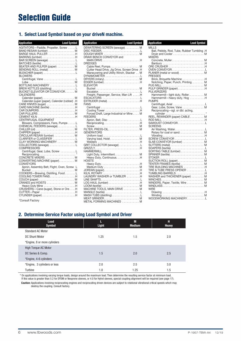
2. Determine Service Factor using Load Symbol and Driver
Application Load SymbolAGITATORS—Paddle, Propeller, Screw . . . . . LBAND RESAW (lumber) . . . . . . . . . . . . . . . . . MBARGE HAUL PULLER . . . . . . . . . . . . . . . . . .HBARKING (lumber) . . . . . . . . . . . . . . . . . . . . . .HBAR SCREEN (sewage) . . . . . . . . . . . . . . . . . . LBATCHES (textile). . . . . . . . . . . . . . . . . . . . . . . LBEATER AND PULPER (paper) . . . . . . . . . . . MBENDING ROLL (metal) . . . . . . . . . . . . . . . . . MBLEACHER (paper). . . . . . . . . . . . . . . . . . . . . . LBLOWERS Centrifugal, Vane . . . . . . . . . . . . . . . . . . . . . L Lobe . . . . . . . . . . . . . . . . . . . . . . . . . . . . . . MBOTTLING MACHINERY . . . . . . . . . . . . . . . . . LBREW KETTLES (distilling). . . . . . . . . . . . . . . . LBUCKET ELEVATOR OR CONVEYOR. . . . . . MCALENDERS Calender (paper). . . . . . . . . . . . . . . . . . . . . M Calender-super (paper), Calender (rubber) .HCANE KNIVES (sugar) . . . . . . . . . . . . . . . . . . MCARD MACHINE (textile) . . . . . . . . . . . . . . . . .HCAR DUMPERS . . . . . . . . . . . . . . . . . . . . . . . .HCAR PULLERS . . . . . . . . . . . . . . . . . . . . . . . . MCEMENT KILN . . . . . . . . . . . . . . . . . . . . . . . . .HCENTRIFUGAL EQUIPMENT Blowers, Compressors, Fans, Pumps . . . . . LCHEMICAL FEEDERS (sewage) . . . . . . . . . . . . LCHILLER (oil) . . . . . . . . . . . . . . . . . . . . . . . . . MCHIPPER (paper) . . . . . . . . . . . . . . . . . . . . . . .HCIRCULAR RESAW (lumber) . . . . . . . . . . . . . MCLARIFIER or CLASSIFIER . . . . . . . . . . . . . . . LCLAY WORKING MACHINERY . . . . . . . . . . . MCOLLECTORS (sewage). . . . . . . . . . . . . . . . . . LCOMPRESSORS Centrifugal, Gear, Lobe, Screw . . . . . . . . . . L Reciprocating . . . . . . . . . . . . . . . . . . . . . . . . *CONCRETE MIXERS . . . . . . . . . . . . . . . . . . . MCONVERTING MACHINE (paper). . . . . . . . . . MCONVEYORS Apron, Assembly Belt, Flight, Oven, Screw L Bucket . . . . . . . . . . . . . . . . . . . . . . . . . . . . MCOOKERS—Brewing, Distilling, Food . . . . . . . LCOOLING TOWER FANS . . . . . . . . . . . . . . . . .HCOUCH (paper) . . . . . . . . . . . . . . . . . . . . . . . MCRANES and HOISTS . . . . . . . . . . . . . . . . . . M Heavy Duty Mine . . . . . . . . . . . . . . . . . . . . .HCRUSHERS—Cane (sugar), Stone or Ore . . . .HCUTTER—Paper . . . . . . . . . . . . . . . . . . . . . . .HCYLINDER (paper) . . . . . . . . . . . . . . . . . . . . . .H
*Consult Factory
Application Load SymbolDEWATERING SCREEN (sewage) . . . . . . . . . MDISC FEEDER. . . . . . . . . . . . . . . . . . . . . . . . . . LDOUGH MIXER . . . . . . . . . . . . . . . . . . . . . . . MDRAW BENCH CONVEYOR and MAIN DRIVE . . . . . . . . . . . . . . . . . . . . . . . . .HDREDGES Cable Reel, Pumps. . . . . . . . . . . . . . . . . . . M Cutter Head Drive, Jig Drive, Screen Drive .H Maneuvering and Utility Winch, Stacker . . MDYNAMOMETER . . . . . . . . . . . . . . . . . . . . . . . LDRYERS (rotary) . . . . . . . . . . . . . . . . . . . . . . . MEDGER (lumber) . . . . . . . . . . . . . . . . . . . . . . . .HELEVATOR Bucket . . . . . . . . . . . . . . . . . . . . . . . . . . . . M Escalator. . . . . . . . . . . . . . . . . . . . . . . . . . . . L Freight, Passenger, Service, Man Lift . . . . .HESCALATORS . . . . . . . . . . . . . . . . . . . . . . . . . LEXTRUDER (metal) . . . . . . . . . . . . . . . . . . . . . .HFANS Centrifugal . . . . . . . . . . . . . . . . . . . . . . . . . . L Cooling Tower . . . . . . . . . . . . . . . . . . . . . . .H Forced Draft, Large Industrial or Mine . . . . MFEEDERS Apron, Belt, Disc . . . . . . . . . . . . . . . . . . . . . L Reciprocating . . . . . . . . . . . . . . . . . . . . . . . .H Screw . . . . . . . . . . . . . . . . . . . . . . . . . . . . . MFILTER, PRESS-OIL . . . . . . . . . . . . . . . . . . . . MGENERATORS Uniform load. . . . . . . . . . . . . . . . . . . . . . . . . L Varying load, Hoist . . . . . . . . . . . . . . . . . . . M Welders . . . . . . . . . . . . . . . . . . . . . . . . . . . .HGRIT COLLECTOR (sewage) . . . . . . . . . . . . . . LGRIZZLY. . . . . . . . . . . . . . . . . . . . . . . . . . . . . .HHAMMERMILL Light Duty, Intermittent. . . . . . . . . . . . . . . . M Heavy Duty, Continuous. . . . . . . . . . . . . . . .HHOISTS Heavy Duty . . . . . . . . . . . . . . . . . . . . . . . . . .H Medium Duty . . . . . . . . . . . . . . . . . . . . . . . MJORDAN (paper). . . . . . . . . . . . . . . . . . . . . . . .HKILN, ROTARY . . . . . . . . . . . . . . . . . . . . . . . . .HLAUNDRY WASHER or TUMBLER . . . . . . . . .HLINE SHAFTS . . . . . . . . . . . . . . . . . . . . . . . . . . LLOG HAUL (lumber) . . . . . . . . . . . . . . . . . . . . .HLOOM (textile) . . . . . . . . . . . . . . . . . . . . . . . . MMACHINE TOOLS, MAIN DRIVE . . . . . . . . . . MMANGLE (textile) . . . . . . . . . . . . . . . . . . . . . . . LMASH TUBS (distilling). . . . . . . . . . . . . . . . . . . LMEAT GRINDER. . . . . . . . . . . . . . . . . . . . . . . MMETAL FORMING MACHINES . . . . . . . . . . . M
Application Load SymbolMILLS Ball, Pebble, Rod, Tube, Rubber Tumbling .H Dryer and Cooler . . . . . . . . . . . . . . . . . . . . MMIXERS Concrete, Muller . . . . . . . . . . . . . . . . . . . . . M Banbury . . . . . . . . . . . . . . . . . . . . . . . . . . . .HORE CRUSHER . . . . . . . . . . . . . . . . . . . . . . . .HOVEN CONVEYOR. . . . . . . . . . . . . . . . . . . . . . LPLANER (metal or wood) . . . . . . . . . . . . . . . . MPRESSES Brick, Briquette Machine . . . . . . . . . . . . . . .H Notching, Paper, Punch, Printing. . . . . . . . MPUG MILL. . . . . . . . . . . . . . . . . . . . . . . . . . . . MPULP GRINDER (paper) . . . . . . . . . . . . . . . . . .HPULVERIZERS Hammermill—light duty, Roller. . . . . . . . . . M Hammermill—heavy duty, Hog . . . . . . . . . .HPUMPS Centrifugal, Axial . . . . . . . . . . . . . . . . . . . . . L Gear, Lobe, Screw, Vane . . . . . . . . . . . . . . M Reciprocating—sgl. or dbl. acting, cylinder . . . . . . . . . . . . . . . . . . . . . . . . . . *REEL, REWINDER (paper) CABLE . . . . . . . . . MROD MILL. . . . . . . . . . . . . . . . . . . . . . . . . . . . .HSAWDUST CONVEYOR . . . . . . . . . . . . . . . . . . LSCREENS Air Washing, Water. . . . . . . . . . . . . . . . . . . . L Rotary for coal or sand. . . . . . . . . . . . . . . . M Vibrating . . . . . . . . . . . . . . . . . . . . . . . . . . . .HSCREW CONVEYOR . . . . . . . . . . . . . . . . . . . . LSLAB CONVEYOR (lumber) . . . . . . . . . . . . . . MSLITTERS (metal) . . . . . . . . . . . . . . . . . . . . . . MSOAPERS (textile) . . . . . . . . . . . . . . . . . . . . . . LSORTING TABLE (lumber) . . . . . . . . . . . . . . . MSPINNER (textile) . . . . . . . . . . . . . . . . . . . . . . MSTOKER . . . . . . . . . . . . . . . . . . . . . . . . . . . . . . LSUCTION ROLL (paper) . . . . . . . . . . . . . . . . . MTENTER FRAMES (textile) . . . . . . . . . . . . . . . MTIRE BUILDING MACHINES . . . . . . . . . . . . . .HTIRE & TUBE PRESS OPENER . . . . . . . . . . . . LTUMBLING BARRELS . . . . . . . . . . . . . . . . . . .HWASHER and THICKENER (paper) . . . . . . . . MWINCHES. . . . . . . . . . . . . . . . . . . . . . . . . . . . MWINDERS, Paper, Textile, Wire . . . . . . . . . . . MWINDLASS . . . . . . . . . . . . . . . . . . . . . . . . . . . MWIRE Drawing . . . . . . . . . . . . . . . . . . . . . . . . . . . .H Winding . . . . . . . . . . . . . . . . . . . . . . . . . . . MWOODWORKING MACHINERY. . . . . . . . . . . . L
1. Select Load Symbol based on your driveN machine.
LoadSymbol
LLight
MMedium
HHeavy
Standard AC Motor
1.25 1.5 2.0DC Shunt Motor
*Engine, 8 or more cylinders
High Torque AC Motor
1.5 2.0 2.5DC Series & Comp.
*Engine, 4-6 cylinders
*Engine, 3 cylinders or less 2.0 2.5 3.0
Turbine 1.0 1.25 1.5
* On applications involving varying torque loads, design around the maximum load. Then determine the resulting service factor at minimum load. If this value is greater than 5.2 for EPDM or Neoprene sleeves, or 4.0 for Hytrel sleeves, special coupling alignment will be required (see page 17).
Caution: Applications involving reciprocating engines and reciprocating driven devices are subject to rotational vibrational critical speeds which may destroy the coupling. Consult factory.
7P-1957-TBW-A4 12/19 www.tbwoods.com
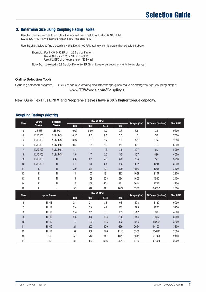
Selection Guide
Use the following formula to calculate the required coupling kilowatt rating @ 100 RPM. KW @ 100 RPM = KW x Service Factor x 100 / coupling RPM
Use the chart below to find a coupling with a KW @ 100 RPM rating which is greater than calculated above.
Example: For 4 KW @ 55 RPM, 1.25 Service Factor: KW @ 100 = 4 x 1.25 x 100 / 55 = 9.09 Use #12 EPDM or Neoprene, or #10 Hytrel.
Note: Do not exceed a 5.2 Service Factor for EPDM or Neoprene sleeves, or 4.0 for Hytrel sleeves.
Coupling Ratings (Metric)
Size Hytrel SleeveKW @ RPM
Torque (Nm) Stiffness (Nm/rad) Max RPM100 970 1450 3000
6 H, HS 2.1 21 31 64 203 1130 6000
7 H, HS 3.4 33 49 102 325 2260 5250
8 H, HS 5.4 52 78 161 512 3390 4500
9 H, HS 8.5 83 124 256 814 5367 3750
10 H, HS 13 130 195 403 1282 11299* 3600
11 H, HS 21 207 309 639 2034 14123* 3600
12 H, HS 37 362 540 1118 3559 25422* 2800
13 HS 56 542 811 1678 5341 41680 2400
14 HS 86 832 1243 2573 8189 67028 2200
SizeEPDM
SleeveNeoprene Sleeve
KW @ RPMTorque (Nm) Stiffness (Nm/rad) Max RPM
100 970 1450 3000
3 JE,JES JN,JNS 0.09 0.90 1.3 2.8 8.8 26 9200
4 E,JE,JES N,JN,JNS 0.18 1.8 2.7 5.5 18 52 7600
5 E,JE,JES N,JN,JNS 0.37 3.6 5.4 11 35 104 7600
6 E,JE,JES N,JN,JNS 0.69 6.7 10 21 66 194 6000
7 E,JE,JES N,JN,JNS 1.1 11 16 33 107 313 5250
8 E,JE,JES N,JN,JNS 1.8 17 25 52 167 490 4500
9 E,JE,JES N 2.8 27 40 83 264 777 3750
10 E,JE,JES N 4.4 43 64 133 422 1241 3600
11 E N 7.0 68 101 209 666 1955 3600
12 E N 11 107 161 332 1058 3107 2800
13 E N 17 169 253 524 1667 4898 2400
14 E N 28 269 402 831 2644 7768 2200
16 E - 56 542 811 1677 5338 20392 1500
3. Determine Size using Coupling Rating Tables
Online Selection Tools Coupling selection program, 3-D CAD models, e-catalog and interchange guide make selecting the right coupling simple!
www.TBWoods.com/Couplings
New! Sure-Flex Plus EPDM and Neoprene sleeves have a 30% higher torque capacity.
8 www.tbwoods.com P-1957-TBW-A4 12/19
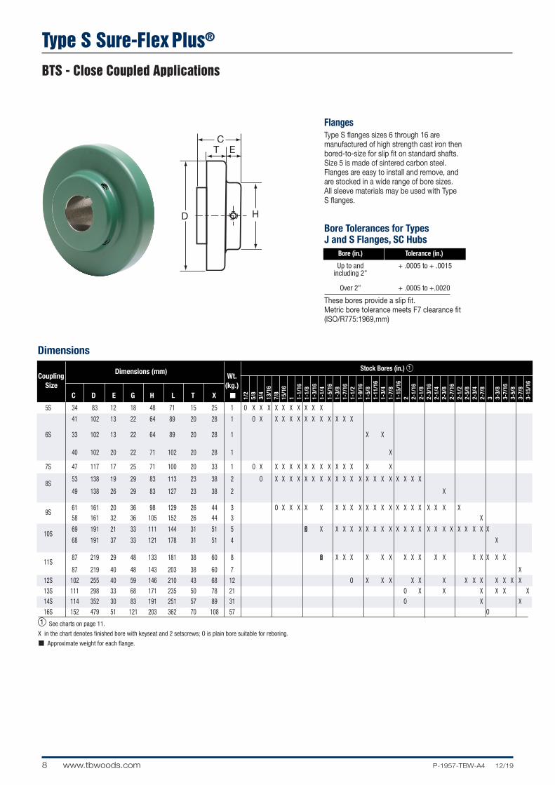
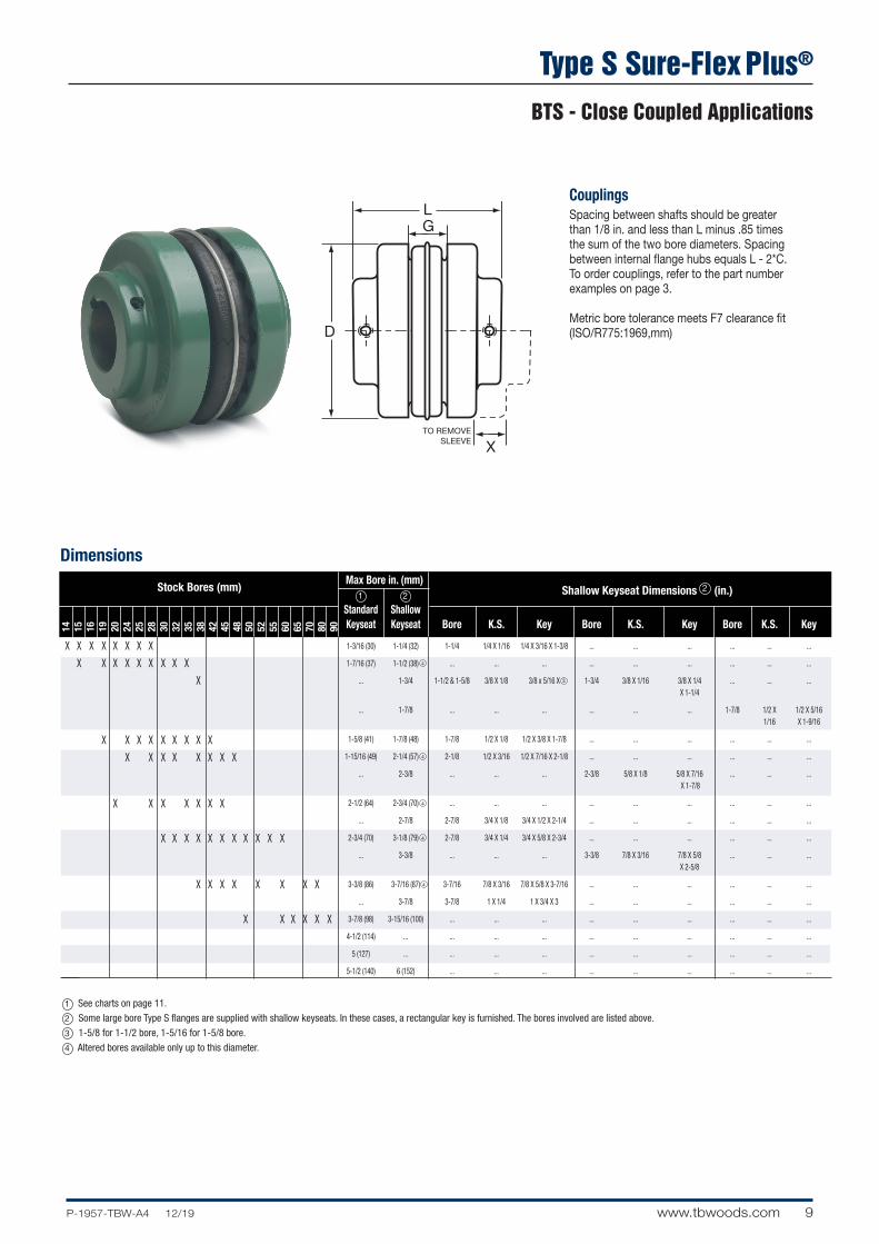
Type S Sure-Flex Plus®
BTS - Close Coupled Applications
H
CT E
FlangesType S flanges sizes 6 through 16 are manufactured of high strength cast iron then bored-to-size for slip fit on standard shafts. Size 5 is made of sintered carbon steel.Flanges are easy to install and remove, and are stocked in a wide range of bore sizes. All sleeve materials may be used with Type S flanges.
Bore Tolerances for Types J and S Flanges, SC Hubs Bore (in.) Tolerance (in.)
Up to and + .0005 to + .0015 including 2”
Over 2” + .0005 to +.0020
These bores provide a slip fit.Metric bore tolerance meets F7 clearance fit (ISO/R775:1969,mm)
Dimensions
1/2
5/8
3/4
13/1
67/
815
/16
1 1-1/
161-
1/8
1-3/
161-
1/4
1-5/
161-
3/8
1-7/
161-
1/2
1-9/
161-
5/8
1-11
/16
1-3/
41-
7/8
1-15
/16
2 2-1/
162-
1/8
2-3/
162-
1/4
2-3/
82-
7/16
2-1/
22-
5/8
2-3/
42-
7/8
3 3-3/
83-
7/16
3-5/
83-
7/8
3-15
/16
Stock Bores (in.) 1
Coupling Dimensions (mm)
Wt. Size (kg.) C D E G H L T X ■
5S 34 83 12 18 48 71 15 25 1 O X X X X X X X X X X
41 102 13 22 64 89 20 28 1 O X X X X X X X X X X X X
6S 33 102 13 22 64 89 20 28 1 X X
40 102 20 22 71 102 20 28 1 X
7S 47 117 17 25 71 100 20 33 1 O X X X X X X X X X X X X X X
8S
53 138 19 29 83 113 23 38 2 O X X X X X X X X X X X X X X X X X X X X
49 138 26 29 83 127 23 38 2 X
9S
61 161 20 36 98 129 26 44 3 O X X X X X X X X X X X X X X X X X X X X X 58 161 32 36 105 152 26 44 3 X
10S
69 191 21 33 111 144 31 51 5 O X X X X X X X X X X X X X X X X X X X X X X
68 191 37 33 121 178 31 51 4 X
11S
87 219 29 48 133 181 38 60 8 O X X X X X X X X X X X X X X X X
87 219 40 48 143 203 38 60 7 X
12S 102 255 40 59 146 210 43 68 12 O X X X X X X X X X X X X X 13S 111 298 33 68 171 235 50 78 21 O X X X X X X 14S 114 352 30 83 191 251 57 89 31 O X X 16S 152 479 51 121 203 362 70 108 57 O 1 See charts on page 11.
X in the chart denotes finished bore with keyseat and 2 setscrews; O is plain bore suitable for reboring.
■ Approximate weight for each flange.
X
X
9P-1957-TBW-A4 12/19 www.tbwoods.com
Type S Sure-Flex Plus®
BTS - Close Coupled Applications
14 15 16 19 20 24 25 28 30 32 35 38 42 45 48 50 52 55 60 65 70 80 90
Dimensions
X X X X X X X X
X X X X X X X X X
X
X X X X X X X X X
X X X X X X X X
X X X X X X X
X X X X X X X X X X X
X X X X X X X X
X X X X X X
L
X
G
TO REMOVESLEEVE
Max Bore in. (mm) 1 2
Standard Shallow Bore K.S. Key Bore K.S. Key Bore K.S. Key Keyseat Keyseat
1-3/16 (30) 1-1/4 (32) 1-1/4 1/4 X 1/16 1/4 X 3/16 X 1-3/8 ... ... ... ... ... ...
1-7/16 (37) 1-1/2 (38) ... ... ... ... ... ... ... ... ...
... 1-3/4 1-1/2 & 1-5/8 3/8 X 1/8 3/8 x 5/16 X 1-3/4 3/8 X 1/16 3/8 X 1/4 ... ... ... X 1-1/4
... 1-7/8 ... ... ... ... ... ... 1-7/8 1/2 X 1/2 X 5/16 1/16 X 1-9/16
1-5/8 (41) 1-7/8 (48) 1-7/8 1/2 X 1/8 1/2 X 3/8 X 1-7/8 ... ... ... ... ... ...
1-15/16 (49) 2-1/4 (57) 2-1/8 1/2 X 3/16 1/2 X 7/16 X 2-1/8 ... ... ... ... ... ...
... 2-3/8 ... ... ... 2-3/8 5/8 X 1/8 5/8 X 7/16 ... ... ... X 1-7/8
2-1/2 (64) 2-3/4 (70) ... ... ... ... ... ... ... ... ...
... 2-7/8 2-7/8 3/4 X 1/8 3/4 X 1/2 X 2-1/4 ... ... ... ... ... ...
2-3/4 (70) 3-1/8 (79) 2-7/8 3/4 X 1/4 3/4 X 5/8 X 2-3/4 ... ... ... ... ... ...
... 3-3/8 ... ... ... 3-3/8 7/8 X 3/16 7/8 X 5/8 ... ... ... X 2-5/8
3-3/8 (86) 3-7/16 (87) 3-7/16 7/8 X 3/16 7/8 X 5/8 X 3-7/16 ... ... ... ... ... ...
... 3-7/8 3-7/8 1 X 1/4 1 X 3/4 X 3 ... ... ... ... ... ...
3-7/8 (98) 3-15/16 (100) ... ... ... ... ... ... ... ... ...
4-1/2 (114) ... ... ... ... ... ... ... ... ... ...
5 (127) ... ... ... ... ... ... ... ... ... ...
5-1/2 (140) 6 (152) ... ... ... ... ... ... ... ... ...
CouplingsSpacing between shafts should be greater than 1/8 in. and less than L minus .85 times the sum of the two bore diameters. Spacing between internal flange hubs equals L - 2*C.To order couplings, refer to the part number examples on page 3.
Metric bore tolerance meets F7 clearance fit (ISO/R775:1969,mm)
Stock Bores (mm) Shallow Keyseat Dimensions 2 (in.)
1 See charts on page 11.
2 Some large bore Type S flanges are supplied with shallow keyseats. In these cases, a rectangular key is furnished. The bores involved are listed above.
3 1-5/8 for 1-1/2 bore, 1-5/16 for 1-5/8 bore.
4 Altered bores available only up to this diameter.
4
3
4
4
4
4
10 www.tbwoods.com P-1957-TBW-A4 12/19
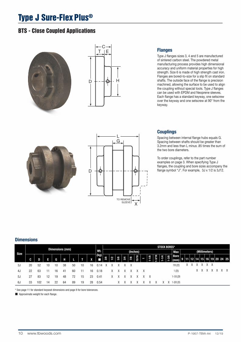
Type J Sure-Flex Plus®
BTS - Close Coupled Applications
STOCK BORES*
9 11 12 14 15 16 19 20 24 25
X X X X X X
X X X X X X X
7/8 (22)
1 (25)
1-1/8 (29)
1-3/8 (35)
(Inches) (Millimeters)MaxBore (mm)
Dimensions
L
X
G
TO REMOVESLEEVE
H
CT E
L
X
G
TO REMOVESLEEVE
H
CT E
FlangesType J flanges sizes 3, 4 and 5 are manufactured of sintered carbon steel. The powdered metal manufacturing process provides high dimensional accuracy and uniform material properties for high strength. Size 6 is made of high strength cast iron. Flanges are bored-to-size for a slip fit on standard shafts. The outside face of the flange is precision machined, allowing the surface to be used to align the coupling without special tools. Type J flanges can be used with EPDM and Neoprene sleeves. Each flange has a standard keyway, one setscrew over the keyway and one setscrew at 90° from the keyway.
CouplingsSpacing between internal flange hubs equals G. Spacing between shafts should be greater than 3.2mm and less than L minus .85 times the sum of the two bore diameters.
To order couplings, refer to the part number examples on page 3. When specifying Type J flanges, the coupling and bore sizes accompany the flange symbol “J”. For example, 3J x 1/2 is 3J12.
* See page 11 for standard keyseat dimensions and page 8 for bore tolerances.
■ Approximate weight for each flange.
Size
Dimensions (mm) Wt. (kg) C D E G H L T X ■
3J 20 52 10 10 38 50 10 16 0.14 X X X X X
4J 22 63 11 16 41 60 11 16 0.18 X X X X X X
5J 27 83 12 19 48 72 15 23 0.41 X X X X X X X
6J 33 102 14 22 64 89 19 28 0.54 X X X X X X X X X
3/8
1/2
5/8
3/4
7/8
15/1
6
1
1-1/
8
1-3/
16
1-1/
4
1-3/
8
11P-1957-TBW-A4 12/19 www.tbwoods.com
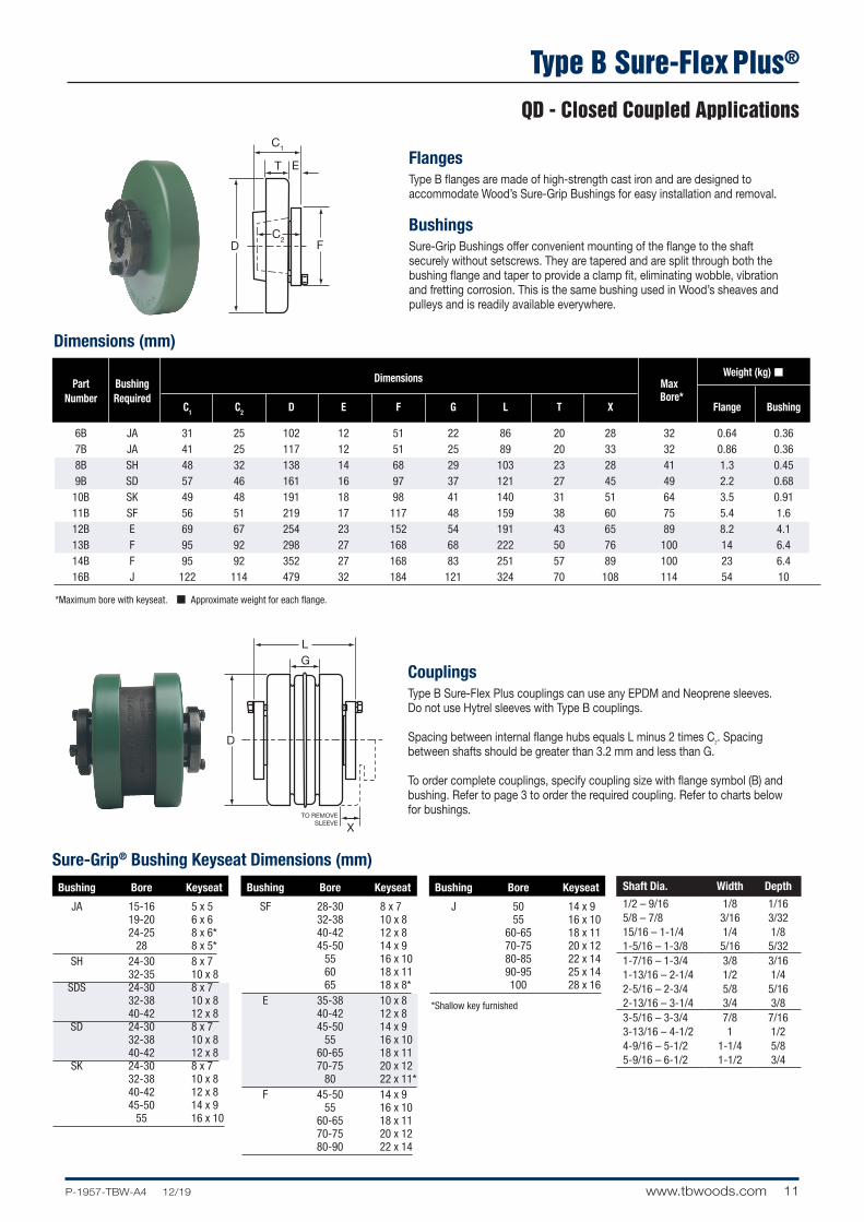
Type B Sure-Flex Plus®
QD - Closed Coupled Applications
L
X
G
TO REMOVESLEEVE
F
C1
C2
T E
L
X
G
TO REMOVESLEEVE
F
C1
C2
T EDimensions (mm)
*Maximum bore with keyseat. ■ Approximate weight for each flange.
Dimensions Weight (kg) ■
Part
Bushing
Max
Number
Required C1 C2 D E F G L T X
Bore* Flange Bushing
6B JA 31 25 102 12 51 22 86 20 28 32 0.64 0.36 7B JA 41 25 117 12 51 25 89 20 33 32 0.86 0.36 8B SH 48 32 138 14 68 29 103 23 28 41 1.3 0.45 9B SD 57 46 161 16 97 37 121 27 45 49 2.2 0.68 10B SK 49 48 191 18 98 41 140 31 51 64 3.5 0.91 11B SF 56 51 219 17 117 48 159 38 60 75 5.4 1.6 12B E 69 67 254 23 152 54 191 43 65 89 8.2 4.1 13B F 95 92 298 27 168 68 222 50 76 100 14 6.4 14B F 95 92 352 27 168 83 251 57 89 100 23 6.4 16B J 122 114 479 32 184 121 324 70 108 114 54 10
FlangesType B flanges are made of high-strength cast iron and are designed to accommodate Wood’s Sure-Grip Bushings for easy installation and removal.
BushingsSure-Grip Bushings offer convenient mounting of the flange to the shaft securely without setscrews. They are tapered and are split through both the bushing flange and taper to provide a clamp fit, eliminating wobble, vibration and fretting corrosion. This is the same bushing used in Wood’s sheaves and pulleys and is readily available everywhere.
CouplingsType B Sure-Flex Plus couplings can use any EPDM and Neoprene sleeves. Do not use Hytrel sleeves with Type B couplings.
Spacing between internal flange hubs equals L minus 2 times C2. Spacing between shafts should be greater than 3.2 mm and less than G.
To order complete couplings, specify coupling size with flange symbol (B) and bushing. Refer to page 3 to order the required coupling. Refer to charts below for bushings.
Bushing Bore Keyseat
JA 15-16 5 x 5 19-20 6 x 6 24-25 8 x 6* 28 8 x 5* SH 24-30 8 x 7 32-35 10 x 8 SDS 24-30 8 x 7 32-38 10 x 8 40-42 12 x 8 SD 24-30 8 x 7 32-38 10 x 8 40-42 12 x 8 SK 24-30 8 x 7 32-38 10 x 8 40-42 12 x 8 45-50 14 x 9 55 16 x 10
Bushing Bore Keyseat
SF 28-30 8 x 7 32-38 10 x 8 40-42 12 x 8 45-50 14 x 9 55 16 x 10 60 18 x 11 65 18 x 8* E 35-38 10 x 8 40-42 12 x 8 45-50 14 x 9 55 16 x 10 60-65 18 x 11 70-75 20 x 12 80 22 x 11* F 45-50 14 x 9 55 16 x 10 60-65 18 x 11 70-75 20 x 12 80-90 22 x 14
Bushing Bore Keyseat
J 50 14 x 9 55 16 x 10 60-65 18 x 11 70-75 20 x 12 80-85 22 x 14 90-95 25 x 14 100 28 x 16
Sure-Grip® Bushing Keyseat Dimensions (mm)
*Shallow key furnished
Shaft Dia. Width Depth
1/2 – 9/16 1/8 1/165/8 – 7/8 3/16 3/3215/16 – 1-1/4 1/4 1/81-5/16 – 1-3/8 5/16 5/321-7/16 – 1-3/4 3/8 3/161-13/16 – 2-1/4 1/2 1/42-5/16 – 2-3/4 5/8 5/162-13/16 – 3-1/4 3/4 3/83-5/16 – 3-3/4 7/8 7/163-13/16 – 4-1/2 1 1/24-9/16 – 5-1/2 1-1/4 5/85-9/16 – 6-1/2 1-1/2 3/4
12 www.tbwoods.com P-1957-TBW-A4 12/19
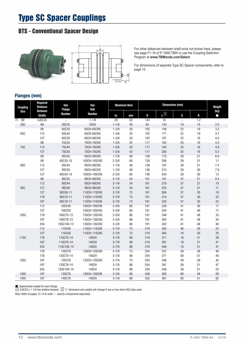
Type SC Spacer CouplingsBTS - Conventional Spacer Design
L
R
G
TO REMOVECENTER
For other distances between shaft ends not shown here, please see page F1-16 of P-1690-TBW or use the Coupling Selection Program at www.TBWoods.com/Select
For dimensions of separate Type SC Spacer components, refer to page 13.
Flanges (mm) Required
Dimensions (mm) Distance Use Use Maximum Bore Weight
Coupling Between Flange Hub (kg)
Size
Shafts Number Number in. mm D L ➁ G R ■ 4JSC ➁ 89 4JSC35 ... 1-1/8 29 62 143 16 ... 1.2 5SC 89 5SC35 5SCH 1-1/8 29 83 143 19 15 2.0 89 6SC35 6SCH-6SCHS 1-3/8 35 102 149 22 19 3.3 6SC 112 6SC44 6SCH-6SCHS 1-3/8 35 102 171 22 19 3.7 127 6SC50 6SCH-6SCHS 1-3/8 35 102 187 22 19 4.0 89 7SC35 7SCH-7SCHS 1-5/8 42 117 162 25 16 4.5 7SC 112 7SC44 7SCH-7SCHS 1-5/8 42 117 184 25 16 4.9 127 7SC50 7SCH-7SCHS 1-5/8 42 117 200 25 16 5.2 89 8SC35 8SCH-8SCHS 1-7/8 48 138 175 29 21 6.9 89 8SC35-10 10SCH-10SCHS 2-3/8 60 138 206 29 21 11 8SC 112 8SC44 8SCH-8SCHS 1-7/8 48 138 197 29 21 7.4 127 8SC50 8SCH-8SCHS 1-7/8 48 138 213 29 30 7.9 127 8SC50-10 10SCH-10SCHS 2-3/8 60 138 244 29 30 12 89 9SC35 9SCH-9SCHS 2-1/8 54 161 191 37 27 8.4 112 9SC44 9SCH-9SCHS 2-1/8 54 161 210 37 27 10 9SC 127 9SC50 9SCH-9SCHS 2-1/8 54 161 225 37 27 11 127 9SC50-11 11SCH-11SCHS 2-7/8 73 161 264 37 30 18 178 9SC70-11 11SCH-11SCHS 2-7/8 73 161 314 37 30 22 197 9SC78-11 11SCH-11SCHS 2-7/8 73 161 333 37 30 23 112 10SC48 10SCH-10SCHS 2-3/8 60 191 238 41 30 17 127 10SC50 10SCH-10SCHS 2-3/8 60 191 244 41 48 17 10SC 178 10SC70-13 13SCH-13SCHS 3-3/8 86 191 346 41 48 33 197 10SC78-13 13SCH-13SCHS 3-3/8 86 191 365 41 48 34 254 10SC100-13 13SCH-13SCHS 3-3/8 86 191 422 41 48 40 112 11SC48 11SCH-11SCHS 2-7/8 73 219 262 48 30 25 127 11SC50 11SCH-11SCHS 2-7/8 73 219 264 18 30 25 11SC 178 11SC70-14 14SCH 3-7/8 98 219 371 18 51 39 197 11SC78-14 14SCH 3-7/8 98 219 391 18 51 41 254 11SC100-14 14SCH 3-7/8 98 219 448 18 51 47 178 12SC70 12SCH-12SCHS 2-7/8 73 254 327 59 38 40 178 12SC70-14 14SCH 3-7/8 98 254 371 59 51 45 12SC 197 12SC78 12SCH-12SCHS 2-7/8 73 254 346 59 38 42 197 12SC78-14 14SCH 3-7/8 98 254 391 59 51 47 254 12SC100-14 14SCH 3-7/8 98 254 448 59 51 52 13SC 197 13SC78 13SCH-13SCHS 3-3/8 86 248 365 68 48 59 14SC 197 14SC78 14SCH 3-7/8 98 352 391 83 51 82
■ Approximate weight for each flange. ➁ 4JSC35 x 1-1/8 has shallow keyseat. ➁ “L” dimension and weight will change if one or two short (HS) hubs used.
Note: Refer to pages 13-14 to order — specify components separately
13P-1957-TBW-A4 12/19 www.tbwoods.com
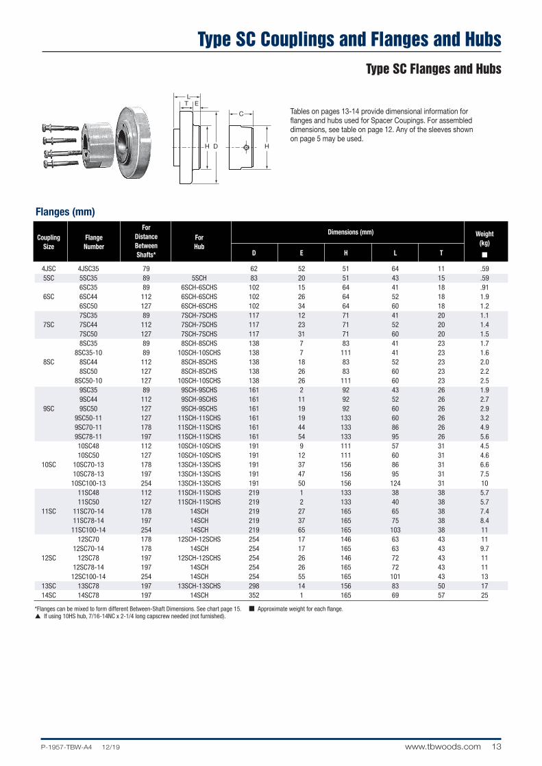
Type SC Couplings and Flanges and HubsType SC Flanges and Hubs
H H
L
C
T E
Flanges (mm) For
Dimensions (mm) Distance Weight
Coupling
Flange
Between For
(kg)
Size
Number
Shafts* Hub
D E H L T ■
4JSC 4JSC35 79 62 52 51 64 11 .59 5SC 5SC35 89 5SCH 83 20 51 43 15 .59 6SC35 89 6SCH-6SCHS 102 15 64 41 18 .91 6SC 6SC44 112 6SCH-6SCHS 102 26 64 52 18 1.9 6SC50 127 6SCH-6SCHS 102 34 64 60 18 1.2 7SC35 89 7SCH-7SCHS 117 12 71 41 20 1.1 7SC 7SC44 112 7SCH-7SCHS 117 23 71 52 20 1.4 7SC50 127 7SCH-7SCHS 117 31 71 60 20 1.5 8SC35 89 8SCH-8SCHS 138 7 83 41 23 1.7 8SC35-10 89 10SCH-10SCHS 138 7 111 41 23 1.6 8SC 8SC44 112 8SCH-8SCHS 138 18 83 52 23 2.0 8SC50 127 8SCH-8SCHS 138 26 83 60 23 2.2 8SC50-10 127 10SCH-10SCHS 138 26 111 60 23 2.5 9SC35 89 9SCH-9SCHS 161 2 92 43 26 1.9 9SC44 112 9SCH-9SCHS 161 11 92 52 26 2.7 9SC 9SC50 127 9SCH-9SCHS 161 19 92 60 26 2.9 9SC50-11 127 11SCH-11SCHS 161 19 133 60 26 3.2 9SC70-11 178 11SCH-11SCHS 161 44 133 86 26 4.9 9SC78-11 197 11SCH-11SCHS 161 54 133 95 26 5.6 10SC48 112 10SCH-10SCHS 191 9 111 57 31 4.5 10SC50 127 10SCH-10SCHS 191 12 111 60 31 4.6 10SC 10SC70-13 178 13SCH-13SCHS 191 37 156 86 31 6.6 10SC78-13 197 13SCH-13SCHS 191 47 156 95 31 7.5 10SC100-13 254 13SCH-13SCHS 191 50 156 124 31 10 11SC48 112 11SCH-11SCHS 219 1 133 38 38 5.7 11SC50 127 11SCH-11SCHS 219 2 133 40 38 5.7 11SC 11SC70-14 178 14SCH 219 27 165 65 38 7.4 11SC78-14 197 14SCH 219 37 165 75 38 8.4 11SC100-14 254 14SCH 219 65 165 103 38 11 12SC70 178 12SCH-12SCHS 254 17 146 63 43 11 12SC70-14 178 14SCH 254 17 165 63 43 9.7 12SC 12SC78 197 12SCH-12SCHS 254 26 146 72 43 11 12SC78-14 197 14SCH 254 26 165 72 43 11 12SC100-14 254 14SCH 254 55 165 101 43 13 13SC 13SC78 197 13SCH-13SCHS 298 14 156 83 50 17 14SC 14SC78 197 14SCH 352 1 165 69 57 25
*Flanges can be mixed to form different Between-Shaft Dimensions. See chart page 15. ■ Approximate weight for each flange. p If using 10HS hub, 7/16-14NC x 2-1/4 long capscrew needed (not furnished).
Tables on pages 13-14 provide dimensional information for flanges and hubs used for Spacer Coupings. For assembled dimensions, see table on page 12. Any of the sleeves shown on page 5 may be used.
14 www.tbwoods.com P-1957-TBW-A4 12/19
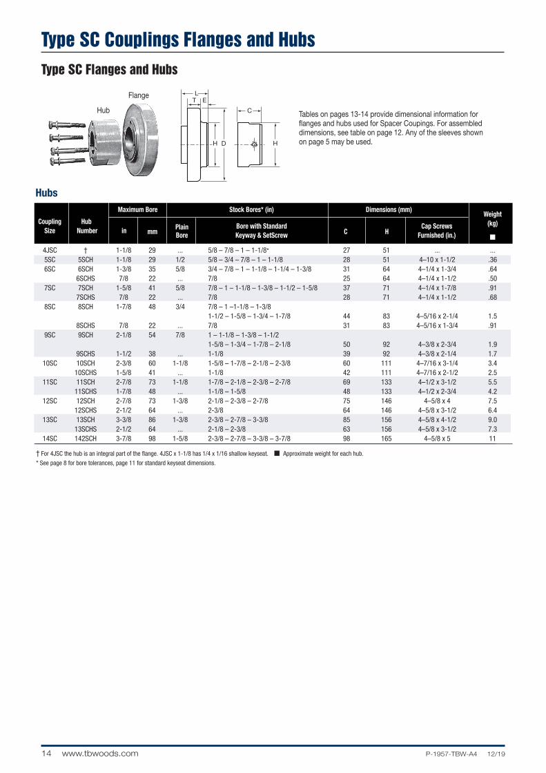
Hubs Maximum Bore Stock Bores* (in) Dimensions (mm)
Weight
Coupling
Hub
Plain Bore with Standard Cap Screws (kg)
Size
Number
in
mm
Bore Keyway & SetScrew C
H
Furnished (in.) ■
4JSC † 1-1/8 29 ... 5/8 – 7/8 – 1 – 1-1/8* 27 51 ... ... 5SC 5SCH 1-1/8 29 1/2 5/8 – 3/4 – 7/8 – 1 – 1-1/8 28 51 4–10 x 1-1/2 .36 6SC 6SCH 1-3/8 35 5/8 3/4 – 7/8 – 1 – 1-1/8 – 1-1/4 – 1-3/8 31 64 4–1/4 x 1-3/4 .64 6SCHS 7/8 22 ... 7/8 25 64 4–1/4 x 1-1/2 .50 7SC 7SCH 1-5/8 41 5/8 7/8 – 1 – 1-1/8 – 1-3/8 – 1-1/2 – 1-5/8 37 71 4–1/4 x 1-7/8 .91 7SCHS 7/8 22 ... 7/8 28 71 4–1/4 x 1-1/2 .68 8SC 8SCH 1-7/8 48 3/4 7/8 – 1 –1-1/8 – 1-3/8 1-1/2 – 1-5/8 – 1-3/4 – 1-7/8 44 83 4–5/16 x 2-1/4 1.5 8SCHS 7/8 22 ... 7/8 31 83 4–5/16 x 1-3/4 .91 9SC 9SCH 2-1/8 54 7/8 1 – 1-1/8 – 1-3/8 – 1-1/2 1-5/8 – 1-3/4 – 1-7/8 – 2-1/8 50 92 4–3/8 x 2-3/4 1.9 9SCHS 1-1/2 38 ... 1-1/8 39 92 4–3/8 x 2-1/4 1.7 10SC 10SCH 2-3/8 60 1-1/8 1-5/8 – 1-7/8 – 2-1/8 – 2-3/8 60 111 4–7/16 x 3-1/4 3.4 10SCHS 1-5/8 41 ... 1-1/8 42 111 4–7/16 x 2-1/2 2.5 11SC 11SCH 2-7/8 73 1-1/8 1-7/8 – 2-1/8 – 2-3/8 – 2-7/8 69 133 4–1/2 x 3-1/2 5.5 11SCHS 1-7/8 48 ... 1-1/8 – 1-5/8 48 133 4–1/2 x 2-3/4 4.2 12SC 12SCH 2-7/8 73 1-3/8 2-1/8 – 2-3/8 – 2-7/8 75 146 4–5/8 x 4 7.5 12SCHS 2-1/2 64 ... 2-3/8 64 146 4–5/8 x 3-1/2 6.4 13SC 13SCH 3-3/8 86 1-3/8 2-3/8 – 2-7/8 – 3-3/8 85 156 4–5/8 x 4-1/2 9.0 13SCHS 2-1/2 64 ... 2-1/8 – 2-3/8 63 156 4–5/8 x 3-1/2 7.3 14SC 142SCH 3-7/8 98 1-5/8 2-3/8 – 2-7/8 – 3-3/8 – 3-7/8 98 165 4–5/8 x 5 11
† For 4JSC the hub is an integral part of the flange. 4JSC x 1-1/8 has 1/4 x 1/16 shallow keyseat. ■ Approximate weight for each hub.
* See page 8 for bore tolerances, page 11 for standard keyseat dimensions.
H H
L
C
T E
Tables on pages 13-14 provide dimensional information for flanges and hubs used for Spacer Coupings. For assembled dimensions, see table on page 12. Any of the sleeves shown on page 5 may be used.
Flange
Hub
Type SC Couplings Flanges and HubsType SC Flanges and Hubs
15P-1957-TBW-A4 12/19 www.tbwoods.com
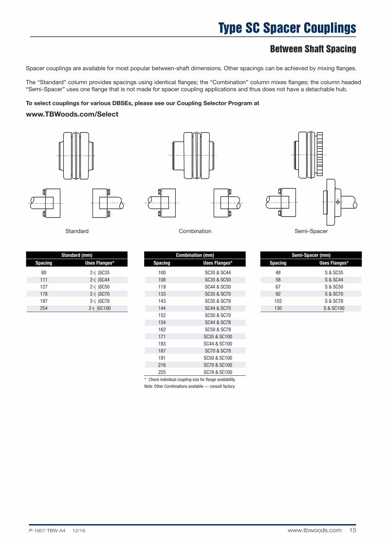
Standard Combination Semi-Spacer
Spacer couplings are available for most popular between-shaft dimensions. Other spacings can be achieved by mixing flanges.
The “Standard” column provides spacings using identical flanges; the “Combination” column mixes flanges; the column headed “Semi-Spacer” uses one flange that is not made for spacer coupling applications and thus does not have a detachable hub.
To select couplings for various DBSEs, please see our Coupling Selector Program at
www.TBWoods.com/Select
Standard (mm)
Spacing Uses Flanges*
80 2-( )SC35 111 2-( )SC44 127 2-( )SC50 178 2-( )SC70 197 2-( )SC78 254 2-( )SC100
Semi-Spacer (mm)
Spacing Uses Flanges*
48 S & SC35 58 S & SC44 67 S & SC50 92 S & SC70 102 S & SC78 130 S & SC100
Combination (mm)
Spacing Uses Flanges*
100 SC35 & SC44 108 SC35 & SC50 119 SC44 & SC50 133 SC35 & SC70 143 SC35 & SC78 144 SC44 & SC70 152 SC50 & SC70 154 SC44 & SC78 162 SC50 & SC78 171 SC35 & SC100 183 SC44 & SC100 187 SC70 & SC78 191 SC50 & SC100 216 SC70 & SC100 225 SC78 & SC100* Check individual coupling size for flange availability.
Note: Other Combinations available — consult factory.
Type SC Spacer CouplingsBetween Shaft Spacing
16 www.tbwoods.com P-1957-TBW-A4 12/19
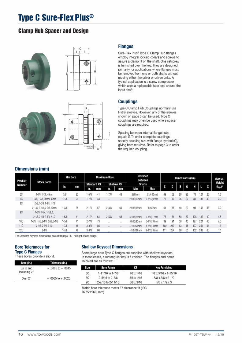
Type C Sure-Flex Plus®
Clamp Hub Spacer and Design
X
G
TO REMOVESLEEVE
H
CT E
L
X
G
TO REMOVESLEEVE
H
CT E
L
FlangesSure-Flex Plus® Type C Clamp Hub flanges employ integral locking collars and screws to assure a clamp fit on the shaft. One setscrew is furnished over the key. They are designed primarily for applications where flanges must be removed from one or both shafts without moving either the driver or driven units. A typical application is a screw compressor which uses a replaceable face seal around the input shaft.
CouplingsType C Clamp Hub Couplings normally use Hytrel sleeves. However, any of the sleeves shown on page 5 can be used. Type C couplings may often be used where spacer couplings are required.
Spacing between internal flange hubs equals G.To order complete couplings, specify coupling size with flange symbol (C), giving bore required. Refer to page 3 to order the required coupling.
Dimensions (mm)
For Standard Keyseat dimensions, see chart page 11. *Weight of one flange.
Metric bore tolerance meets F7 clearance fit (ISO/R775:1969, mm)
Min Bore Maximum Bore Distance Between
Dimensions (mm) Approx.
Product
Standard KS Shallow KS Shafts Weight
Number
Stock Bores
in. mm in. mm in. mm Min Max C D E G H L X (kg.)*
6C 1-1/8, 1-7/8, 40mm 7/8 22 1-5/8 41 1-7/8 48 2 (51mm) 2-3/4 (70mm) 49 102 29 22 76 121 25 1.6 7C 1-3/8, 1-7/8, 35mm, 40mm 1-1/8 29 1-7/8 48 ... ... 2-5/16 (59mm) 3-7/16 (87mm) 71 117 36 27 83 138 30 2.0 8C 1/3/8, 1-5/8, 1-3/4, 1-7/8 2-1/8, 2-1/4, 2-3/8, 40mm 1-3/8 35 2-1/4 57 2-3/8 60 2-9/16 (65mm) 4 (102mm) 64 138 40 29 98 156 35 3.0 9C 1-5/8, 1-3/4, 1-7/8, 2, 2-1/8, 2-1/4, 2-3/8, 2-1/2 1-5/8 41 2-1/2 64 2-5/8 68 3-1/16 (78mm) 4-5/8 (117mm) 76 161 50 37 108 189 40 4.5 10C 1-5/8, 1-7/8, 2-1/4, 2-3/8, 2-1/2 1-5/8 41 2-7/8 73 ... ... 3-9/16 (90mm) 5-1/4 (133mm) 89 191 58 43 127 221 46 7.5 11C 2-1/8, 2-3/8, 2-1/2 1-7/8 48 3-3/8 86 ... ... 4-1/8 (105mm) 5-7/8 (149mm) 102 219 63 48 137 251 54 12 12C 2-1/8 1-7/8 48 3-3/8 86 ... ... 4-7/8 (124mm) 6-1/2 (165mm) 111 254 68 60 152 283 60 17
Bore Tolerances for Type C FlangesThese bores provide a slip fit.
Bore (in.) Tolerance (in.)
Up to and + .0005 to + .0015 including 2”
Over 2” + .0005 to + .0020
Shallow Keyseat DimensionsSome large bore Type C flanges are supplied with shallow keyseats. In these cases, a rectangular key is furnished. The flanges and bores involved are as follows:
Size Bore Range KS Key Furnished
6C 1-11/16 to 1-7/8 1/2 x 1/16 1/2 x 5/16 x 1-15/16 8C 2-5/16 to 2-3/8 5/8 x 1/16 5/8 x 3/8 x 2-1/2 9C 2-7/16 to 2-11/16 5/8 x 3/16 5/8 x 1/2 x 3
17P-1957-TBW-A4 12/19 www.tbwoods.com
Installation Instructions
Sure-Flex Plus flanges (outer metallic parts) and sleeves (inner elastomeric elements) come in many sizes and types. First, determine the size and type of components being used. Check maximum RPM values in the table below against operating speed. Remove all components from their boxes, and loosely assemble the coupling on any convenient surface. (If using a two-piece E or N sleeve, do not install the wire ring at this time.)
1. Inspect all coupling components and remove any protective coatings or lubricants from bores, mating surfaces and fasteners. Remove any existing burrs, etc. from the shafts.
2. Slide one coupling flange onto each shaft using keys where required. When using Type B flanges, follow the instructions furnished with the Sure-Grip bushings.
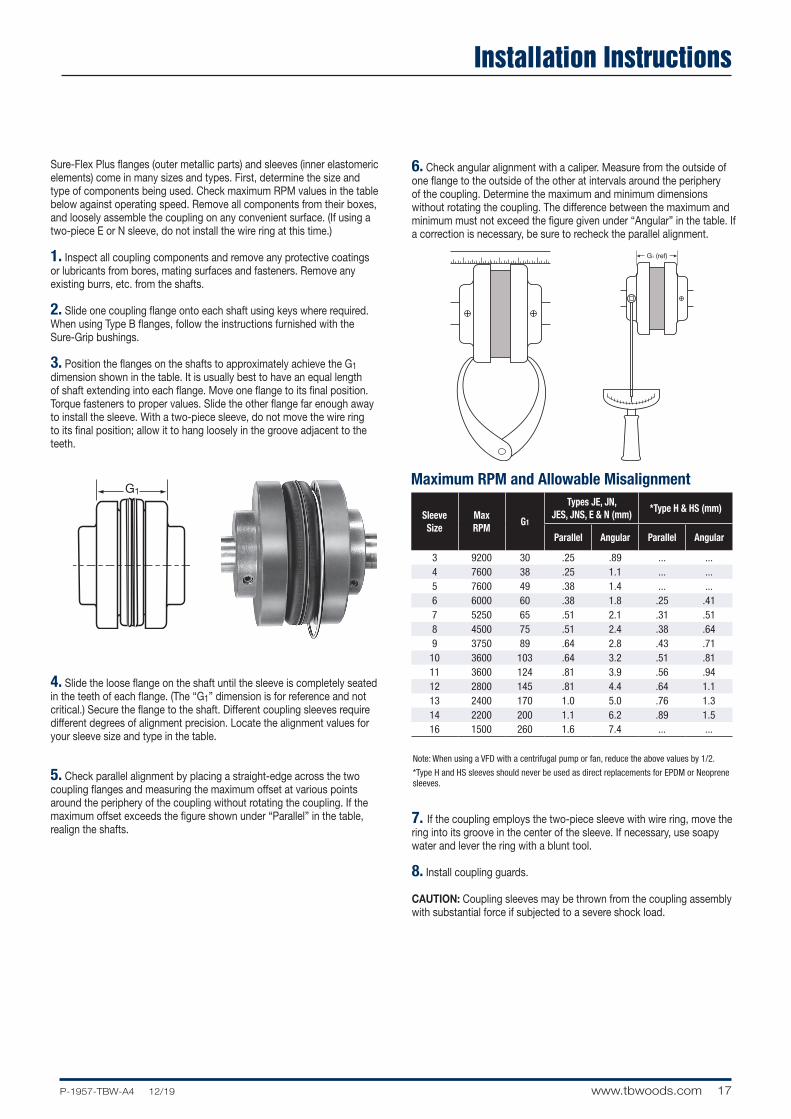
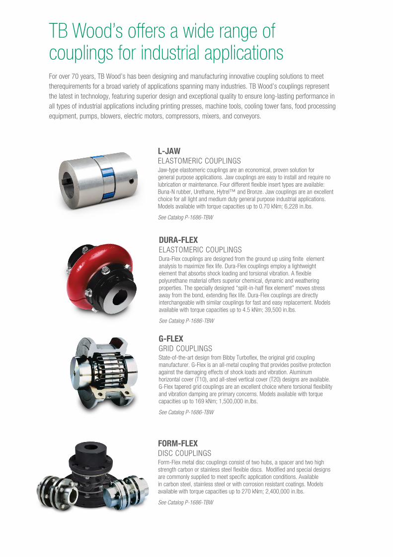
3. Position the flanges on the shafts to approximately achieve the G1 dimension shown in the table. It is usually best to have an equal length of shaft extending into each flange. Move one flange to its final position. Torque fasteners to proper values. Slide the other flange far enough away to install the sleeve. With a two-piece sleeve, do not move the wire ring to its final position; allow it to hang loosely in the groove adjacent to the teeth.
4. Slide the loose flange on the shaft until the sleeve is completely seated in the teeth of each flange. (The “G1” dimension is for reference and not critical.) Secure the flange to the shaft. Different coupling sleeves require different degrees of alignment precision. Locate the alignment values for your sleeve size and type in the table.
5. Check parallel alignment by placing a straight-edge across the two coupling flanges and measuring the maximum offset at various points around the periphery of the coupling without rotating the coupling. If the maximum offset exceeds the figure shown under “Parallel” in the table, realign the shafts.
6. Check angular alignment with a caliper. Measure from the outside of one flange to the outside of the other at intervals around the periphery of the coupling. Determine the maximum and minimum dimensions without rotating the coupling. The difference between the maximum and minimum must not exceed the figure given under “Angular” in the table. If a correction is necessary, be sure to recheck the parallel alignment.
7. If the coupling employs the two-piece sleeve with wire ring, move the ring into its groove in the center of the sleeve. If necessary, use soapy water and lever the ring with a blunt tool.
8. Install coupling guards.
CAUTION: Coupling sleeves may be thrown from the coupling assembly with substantial force if subjected to a severe shock load.
G1Maximum RPM and Allowable Misalignment
Note: When using a VFD with a centrifugal pump or fan, reduce the above values by 1/2.
*Type H and HS sleeves should never be used as direct replacements for EPDM or Neoprene sleeves.
G1 (ref)
Sleeve Size
Max RPM
G1
Types JE, JN, JES, JNS, E & N (mm)
*Type H & HS (mm)
Parallel Angular Parallel Angular
3 9200 30 .25 .89 ... ...4 7600 38 .25 1.1 ... ...5 7600 49 .38 1.4 ... ...6 6000 60 .38 1.8 .25 .417 5250 65 .51 2.1 .31 .518 4500 75 .51 2.4 .38 .649 3750 89 .64 2.8 .43 .71
10 3600 103 .64 3.2 .51 .8111 3600 124 .81 3.9 .56 .9412 2800 145 .81 4.4 .64 1.113 2400 170 1.0 5.0 .76 1.314 2200 200 1.1 6.2 .89 1.516 1500 260 1.6 7.4 ... ...

18 www.tbwoods.com P-1957-TBW-A4 12/19
Notes
For over 70 years, TB Wood’s has been designing and manufacturing innovative coupling solutions to meet therequirements for a broad variety of applications spanning many industries. TB Wood’s couplings represent the latest in technology, featuring superior design and exceptional quality to ensure long-lasting performance in all types of industrial applications including printing presses, machine tools, cooling tower fans, food processing equipment, pumps, blowers, electric motors, compressors, mixers, and conveyors.
TB Wood’s offers a wide range of couplings for industrial applications
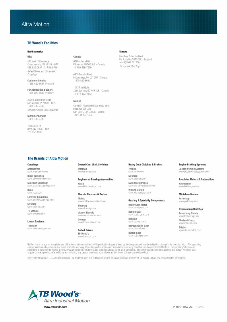
FORM-FLEX DISC COUPLINGSForm-Flex metal disc couplings consist of two hubs, a spacer and two high strength carbon or stainless steel flexible discs. Modified and special designs are commonly supplied to meet specific application conditions. Available in carbon steel, stainless steel or with corrosion resistant coatings. Models available with torque capacities up to 270 kNm; 2,400,000 in.lbs.
See Catalog P-1686-TBW
L-JAW ELASTOMERIC COUPLINGSJaw-type elastomeric couplings are an economical, proven solution for general purpose applications. Jaw couplings are easy to install and require no lubrication or maintenance. Four different flexible insert types are available: Buna-N rubber, Urethane, Hytrel™ and Bronze. Jaw couplings are an excellent choice for all light and medium duty general purpose industrial applications. Models available with torque capacities up to 0.70 kNm; 6,228 in.lbs.
See Catalog P-1686-TBW
DURA-FLEX ELASTOMERIC COUPLINGSDura-Flex couplings are designed from the ground up using finite element analysis to maximize flex life. Dura-Flex couplings employ a lightweight element that absorbs shock loading and torsional vibration. A flexible polyurethane material offers superior chemical, dynamic and weathering properties. The specially designed “split-in-half flex element” moves stress away from the bond, extending flex life. Dura-Flex couplings are directly interchangeable with similar couplings for fast and easy replacement. Models available with torque capacities up to 4.5 kNm; 39,500 in.lbs.
See Catalog P-1686-TBW
G-FLEX GRID COUPLINGSState-of-the-art design from Bibby Turboflex, the original grid coupling manufacturer. G-Flex is an all-metal coupling that provides positive protection against the damaging effects of shock loads and vibration. Aluminum horizontal cover (T10), and all-steel vertical cover (T20) designs are available. G-Flex tapered grid couplings are an excellent choice where torsional flexibility and vibration damping are primary concerns. Models available with torque capacities up to 169 kNm; 1,500,000 in.lbs.
See Catalog P-1686-TBW
Altra Motion
www.tbwoods.com P-1957-TBW-A4 12/19
The Brands of Altra Motion
Couplings
Ameridriveswww.ameridrives.com
Bibby Turbo� ex www.bibbyturbo� ex.com
Guardian Couplingswww.guardiancouplings.com
Hucowww.huco.com
Lami� ex Couplingswww.lami� excouplings.com
Stromag www.stromag.com
TB Wood’swww.tbwoods.com
Linear Systems
Thomsonwww.thomsonlinear.com
Geared Cam Limit Switches
Stromagwww.stromag.com
Engineered Bearing Assemblies
Kilianwww.kilianbearings.com
Electric Clutches & Brakes
Matrixwww.matrix-international.com
Stromagwww.stromag.com
Warner Electricwww.warnerelectric.com
Deltranwww.thomsonlinear.com
Belted DrivesTB Wood’s www.tbwoods.com
Heavy Duty Clutches & Brakes
Twi� exwww.twi� ex.com
Stromagwww.stromag.com
Svendborg Brakeswww.svendborg-brakes.com
Wichita Clutchwww.wichitaclutch.com
Gearing & Specialty Components
Bauer Gear Motorwww.bauergears.com
Boston Gearwww.bostongear.com
Delevanwww.delevan.com
Delroyd Worm Gearwww.delroyd.com
Nuttall Gearwww.nuttallgear.com
Engine Braking Systems
Jacobs Vehicle Systemswww.jacobsvehiclesystems.com
Precision Motors & Automation
Kollmorgenwww.kollmorgen.com
Miniature Motors
Portescapwww.portescap.com
Overrunning Clutches
Formsprag Clutchwww.formsprag.com
Marland Clutchwww.marland.com
Stieberwww.stieberclutch.com
TB Wood’s Facilities
North America
USA
440 North Fifth AvenueChambersburg, PA 17201 - USA888-829-6637 * 717-264-7161
Belted Drives and Elastomeric Couplings
Customer Service1-888-829-6637 (Press #5)
For Application Support1-888-829-6637 (Press #7)
2000 Clovis Barker RoadSan Marcos, TX 78666 - USA1-888-449-9439
General Purpose Disc Couplings
Customer Service1-888-449-9439
4970 Joule StReno, NV 89502 - USA775-857-1800
Canada
9779 45 Ave NWEdmonton, AB T6E 5V8 - Canada+1 780-439-7979
6305 Danville RoadMississauga, ON L5T 2H7 - Canada1-800-829-6631
1073 Rue BéginSaint-Laurent, QC H4R 1V8 - Canada+1 514-332-4812
Mexico
Comisión Federal de Electricidad 850, Industrial San Luis, San Luis, S.L.P., 78395 - Mexico+52 444 137 1500
Europe
Merchant Drive, HertfordHertfordshire SG13 7BL - England+44(0)1992 501900
Elastomeric Couplings
Neither the accuracy nor completeness of the information contained in this publication is guaranteed by the company and may be subject to change in its sole discretion. The operating and performance characteristics of these products may vary depending on the application, installation, operating conditions and environmental factors. The company’s terms and conditions of sale can be viewed at http://www.altramotion.com/terms-and-conditions/sales-terms-and-conditions. These terms and conditions apply to any person who may buy, acquire or use a product referred to herein, including any person who buys from a licensed distributor of these branded products.
©2019 by TB Wood’s LLC. All rights reserved. All trademarks in this publication are the sole and exclusive property of TB Wood’s LLC or one of its af� liated companies.


