Usability of Long Term Evolution (LTE) in DLR’s Research Aircraft DO 228-212 Daniel Rosigkeit Microwaves and Radar Institute German Aerospace Center, Oberpfaffenhofen, Germany Fachhochschule Lübeck, Lübeck, Germany [email protected]Stefan V. Baumgartner, Anton Nottensteiner Microwaves and Radar Institute German Aerospace Center (DLR) Oberpfaffenhofen, Germany [email protected], [email protected]Abstract—In the paper the usability of long term evolution (LTE) data transmission from an aircraft to the ground is investigated. Theoretical analyses and experimental measurements have been carried out by using a commercial low- cost LTE modem and the existing LTE base station infrastructure on ground. In the airborne experiment over wide areas a stable LTE connection was achieved. Keywords—LTE, data transmission, aircraft, synthetic aperture radar, traffic monitoring I. INTRODUCTION The DLR project VABENE++ deals with traffic management for large scale events and disasters [1]. One sensor used in VABENE++ is DLR’s multi-channel synthetic aperture radar (SAR) system F-SAR installed onboard a Dornier DO 228-212 research aircraft [4]. This system has the challenging task to acquire, process and deliver relevant traffic products to a dedicated traffic management center in realtime. SAR image and traffic data processing have to be carried out directly onboard the aircraft [5]. The relevant SAR image patch (size of several MByte) and traffic data (size of a few kByte) have to be transmitted to a ground station and transferred to a server. So far for data transmission an optical laser communication link and a microwave data link have been used. Both links require a dedicated (mobile) ground station, which under circumstances might be difficult to install close to the event or disaster location within a small timeframe. Which so far was not considered as an alternative and low- cost data transmission technique is long term evolution (LTE). In recent years several test where made with the LTE network in a high speed Transrapid train moving with up to 430 km/h. A stable connection with data rates of 36 Mbit/s was achieved [2]. Also first airborne experiments with an Airbus A320 and some special not off-the-shelf ground stations, with antennas oriented to the sky, were very promising [3]. In the case of this VABENE++ related DLR study, we wanted to know whether the existing standard LTE infrastructure of the German Telekom can be used with a commercially available LTE modem, for transmitting radar images and traffic data from the aircraft to the ground and internet. The hardware, integration, maintenance and operation costs are expected to be relatively low in comparison to a dedicated microwave link, which additionally requires a (mobile) ground station and a time and location dependent operation license. II. PERFORMANCE PARAMETERS AND SIMULATION Important LTE performance parameters are the data rate, the signal-to-interference plus noise ratio (SINR), the received signal strength indicator (RSSI), the reference signal received power (RSRP), and the reference signal received quality (RSRQ) [6]. These parameters are mainly influenced by the transmit power of the user equipment installed in the aircraft, the distance between the base station and the aircraft, and the patterns and tilt angles of the antennas installed in the base stations on ground and in the aircraft. The RSRP value, expressed in dBm, represents the power contained in one LTE carrier of 15 kHz bandwidth. With the RSRP parameter different cells using the same carrier frequency can be compared in the LTE network and handover decisions can be made. However, the RSRP and the closely related RSSI values alone can generally not be used for drawing final conclusions regarding the signal quality, which is influenced by noise, intersymbol interferences (ISI) and other disturbing interferences. For assessing the signal quality more comprehensively, the SINR and RSRQ values can be used. In Table 1 a classification of different RSRP, SINR and RSRQ values is made [7]. When the RSRP, SINR and RSRQ values are known a qualitative statement regarding receiving quality and usability of the LTE signal can be made. TABLE 1. QUALITY AND USABILITY OF THE LTE SIGNAL [7] RSRP [dBm] SINR [dB] RSRQ [dB] Receiving Quality Usability of the Signal >-70 to -79 >10 -3 to -5 very good level VoIP, very high data rate -80 to -89 6 to 10 -6 to -8 good level high data rate -90 to -100 0 to 5 -9 to -15 average level half data rate -101 to -110 <0 -16 to -20 poor signal non stable connection For a rough theoretical performance assessment, i.e., to evaluate if LTE reception onboard the aircraft is principally possible, it is sufficient to compute the expected RSRP values.
Transcript
Usability of Long Term Evolution (LTE) in DLR’s Research Aircraft DO 228-212
Daniel Rosigkeit Microwaves and Radar Institute
German Aerospace Center, Oberpfaffenhofen, Germany Fachhochschule Lübeck, Lübeck, Germany
Abstract—In the paper the usability of long term evolution (LTE) data transmission from an aircraft to the ground is investigated. Theoretical analyses and experimental measurements have been carried out by using a commercial low-cost LTE modem and the existing LTE base station infrastructure on ground. In the airborne experiment over wide areas a stable LTE connection was achieved.
Keywords—LTE, data transmission, aircraft, synthetic aperture radar, traffic monitoring
I. INTRODUCTION
The DLR project VABENE++ deals with traffic management for large scale events and disasters [1]. One sensor used in VABENE++ is DLR’s multi-channel synthetic aperture radar (SAR) system F-SAR installed onboard a Dornier DO 228-212 research aircraft [4]. This system has the challenging task to acquire, process and deliver relevant traffic products to a dedicated traffic management center in realtime. SAR image and traffic data processing have to be carried out directly onboard the aircraft [5].
The relevant SAR image patch (size of several MByte) and traffic data (size of a few kByte) have to be transmitted to a ground station and transferred to a server. So far for data transmission an optical laser communication link and a microwave data link have been used. Both links require a dedicated (mobile) ground station, which under circumstances might be difficult to install close to the event or disaster location within a small timeframe.
Which so far was not considered as an alternative and low-cost data transmission technique is long term evolution (LTE). In recent years several test where made with the LTE network in a high speed Transrapid train moving with up to 430 km/h. A stable connection with data rates of 36 Mbit/s was achieved [2]. Also first airborne experiments with an Airbus A320 and some special not off-the-shelf ground stations, with antennas oriented to the sky, were very promising [3].
In the case of this VABENE++ related DLR study, we wanted to know whether the existing standard LTE infrastructure of the German Telekom can be used with a commercially available LTE modem, for transmitting radar images and traffic data from the aircraft to the ground and internet. The hardware, integration, maintenance and operation costs are expected to be relatively low in comparison to a
dedicated microwave link, which additionally requires a (mobile) ground station and a time and location dependent operation license.
II. PERFORMANCE PARAMETERS AND SIMULATION
Important LTE performance parameters are the data rate, the signal-to-interference plus noise ratio (SINR), the received signal strength indicator (RSSI), the reference signal received power (RSRP), and the reference signal received quality (RSRQ) [6]. These parameters are mainly influenced by the transmit power of the user equipment installed in the aircraft, the distance between the base station and the aircraft, and the patterns and tilt angles of the antennas installed in the base stations on ground and in the aircraft.
The RSRP value, expressed in dBm, represents the power contained in one LTE carrier of 15 kHz bandwidth. With the RSRP parameter different cells using the same carrier frequency can be compared in the LTE network and handover decisions can be made. However, the RSRP and the closely related RSSI values alone can generally not be used for drawing final conclusions regarding the signal quality, which is influenced by noise, intersymbol interferences (ISI) and other disturbing interferences. For assessing the signal quality more comprehensively, the SINR and RSRQ values can be used.
In Table 1 a classification of different RSRP, SINR and RSRQ values is made [7]. When the RSRP, SINR and RSRQ values are known a qualitative statement regarding receiving quality and usability of the LTE signal can be made.
TABLE 1. QUALITY AND USABILITY OF THE LTE SIGNAL [7]
RSRP [dBm] SINR [dB]
RSRQ [dB]
Receiving Quality
Usability of the Signal
>-70 to -79 >10 -3 to -5 very good
level VoIP, very
high data rate
-80 to -89 6 to 10 -6 to -8 good level high data rate
-90 to -100 0 to 5 -9 to -15 average
level half data rate
-101 to -110 <0 -16 to -20 poor signal non stable connection
For a rough theoretical performance assessment, i.e., to
evaluate if LTE reception onboard the aircraft is principally possible, it is sufficient to compute the expected RSRP values.
The RSRP corresponds approximately to the received power ��� in one channel which can be computed as
��� ���� ⋅ ��� ⋅ ���
4 ⋅ ⋅ �� ⋅ (1)
where ��� is the transmitted power in one channel, ��� is the transmit antenna gain, ��� is the effective area of the receiving antenna, � is the distance between the transmit (TX) and receiving (RX) antenna, and are the losses.
The antenna main lobes of the LTE base stations are generally directed towards to the Earth with tilt angels between 0° and -10°. Therefore, the signals which will be received in the aircraft may originate from the side lobes and from reflections from the ground. For the theoretical analyses and simulations we have only considered the side lobes of the antennas, but have ignored potential ground reflections.
In Fig. 1 the received power ��� at the base station is plotted for two different aircraft altitudes of 2000 m (in blue color) and 3000 m (black) above ground. As base station antenna pattern for simplification purposes an ideally SINC shaped elevation antenna pattern is considered and in the aircraft an antenna with 0 dBi gain is assumed. The transmit power in the aircraft is set to ��� � 200 mW � 23 dBm. With 0 dBi antenna gain also the equivalent intrinsic radiated power ���� � ��� ⋅ ��� corresponds to the same value of 23 dBm, which is just the maximum ���� allowed by law in Germany. For the simulation no additional losses are considered (i.e., � 0 dB), a RX antenna tilt angle of -10° is assumed, and the effective antenna area ��� is computed by considering the elevation dependent RX antenna gain:
��� ��� ⋅ ��������
4 ⋅ (2)
where ��� is the elevation angle.
Fig. 1. Expected receiving power ��� as a function of ground distance for an aircraft altitude of 2 km (blue color) and 3 km (black) above ground.
By comparing the simulation results in Fig. 1 with the RSRP values listed in Table 1, we expect at least an average receiving quality level with half data rate since the RX power is larger than -100 dBm over a wide range. The antenna pattern notches in Fig. 1 are practically less relevant since we
expect, as already mentioned, to receive also signals from ground reflections which might be much larger.
III. EXPERIMENTAL RESULTS
The experiment was conducted with the DLR research aircraft DO 228-212 where the modem FRITZ!Box 6842 LTE with the German Telekom as provider was used. The modem was installed in the right observation window with a depression angle of approximately 40 degree (Fig. 2 right). The flight track was recorded by a GPS tracker and all the measurement data from the FRITZ!Box were logged every two seconds by using a Python script which read the measurement data from the FRITZ!Box’s web interface.
Fig. 2. DLR’s DO 228-212 research aircraft (left) and right observation window with installed LTE FRITZ!Box modem (right).
The flight track for carrying out the measurements was carefully planned taking into account the known positions of the base stations on ground. Two laps in different altitudes of 2400 m and 3350 m above mean sea level have been flown. The measured data corresponding to these altitudes have been spatially synchronized so that a direct LTE performance comparison of the different altitudes is possible.
The LTE base station may transmit simultaneously two signals with different polarizations. The FRITZ!Box has two internal antennas and each of these antennas can receive both transmitted signals. Thus, in total four received signals with different RSRP, SINR and RSRQ values are measured. When the FRITZ!Box is operated in the diversity mode, the signal with the best quality is selected for data reception.
In Fig. 3 the measured maximum RSRP values are plotted (i.e., the maximum of the four RSRP values available at each measurement interval). Missing values indicate that the LTE connection was interrupted. Most of the valid RSRP values are within the -100 to -80 dBm interval. According to Table 1 this interval corresponds to an average to good receiving quality. The RSRP values at 2400 m altitude are generally better than at 3350 m.
The maximum RSRQ values are plotted in Fig. 4. They behave similar as the RSRP values: for the lower altitude of 2400 m higher values and, hence, a better LTE performance is observable. Many RSRQ values corresponding to 3350 m altitude are below -15 dB, which indicates, according to Table 1, a poor signal quality and an unstable LTE connection. From this point of view it is recommended to choose the lower altitude for the envisaged traffic monitoring application.
The measured maximum SINR values plotted in Fig. 5 are higher for the lower altitude (blue line). Values between 0 and 10 dB indicate an average to good receiving signal quality with
half data rate (cf. Table 1). For values below 0 dB, as this is the case for a number of values corresponding to 3350 m altitude, only a poor signal quality and an unstable LTE connection can be achieved.
Fig. 3. Measured maximum RSRP values as a function of observation time for an aircraft altitude of 2400 m (blue) and 3350 m (black) above mean sea level.
Fig. 4. Measured RSRQ values as a function of observation time for an aircraft altitude of 2400 m (blue) and 3350 m (black) above mean sea level.
Fig. 5. Measured SINR values as a function of observation time for an aircraft altitude of 2400 m (blue) and 3350 m (black) above mean sea level.
The FRITZ!Box is also able to measure the usable TX and RX data rates. The measured results for an altitude of 2400 m are depicted in Fig. 6. The data rates over wide regions are comparable with a home DSL connection. However, a strong fluctuation between approximately 2 and 20 MBit/s is observable for the RX case. The usable TX data rate, which is importance for transmitting the radar and traffic data to ground,
is over wide regions higher than 20 MBit/s. Apart from the obviously unstable connection with several interruptions, it was possible to upload a larger radar image of 270 MByte size to the Dropbox cloud storage without problems. The transfer took approximately 14 minutes, which results in an effective average TX data rate of 321 kByte/s. This effective data rate is sufficiently high for a regular transmission of realtime traffic data (i.e., vehicle positions, velocities and moving directions), which have only a size of a few kByte. From the VABENE++ operational point of view large radar images of several MByte size need not to be transmitted in realtime, a time lag of a few minutes is tolerable.
Fig. 6. Measured useable RX (blue) and TX (black) data rates as a function of observation time for an aircraft altitude of 2400 m above mean sea level.
All measured data have been gelocated by synchronizing the GPS track with the measurements. Keyhole markup language (KML) data files were generated for visualizing the geocoded measurements with Google Earth.
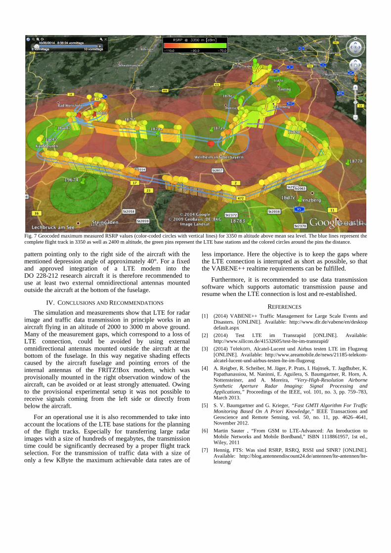
In Fig. 7 one can see in blue the whole flight track in 2400 and 3350 m altitude above mean sea level. The vertical color-coded lines, with a circle at the top, are the measured maximum RSRP values for a flight altitude of 3350 m. The length of the lines as well as the line and circle color represents the measured RSRP values. Green corresponds to a good signal (≥ -70 dBm) and red to poor signal strength (≤ -110 dBm).
The green pins are the known locations of the LTE base stations. They were found with the help of an online available net coverage map. Each LTE base station was visited prior to the flight to ensure that it really exists and to acquire important data for later evaluation, e.g., the eNodeB IDs of the stations. The colored circles around the base stations correspond to the broadcast radius on ground, where green is a radius of up to 6 km, yellow up to 9 and red up to 15 km. The aim of the flight track planning was to ensure that the horizontal distance between the base station and the aircraft as far as possible is not larger than 10 km. According to Fig. 1 this would ensure that the RSRP values are larger than -95 dBm if the practically less relevant notches caused by the base station antenna pattern are neglected.
The gaps in the measured RSRP data shown in Fig. 7 occur mainly half way between two LTE base stations and directly above the base stations. This behavior was expected since the FRITZ!Box has no omnidirectional but a directed antenna
RS
RQ
[dB
] S
INR
[dB
]
pattern pointing only to the right side of the aircraft with the mentioned depression angle of approximately 40°. For a fixed and approved integration of a LTE modem into the DO 228-212 research aircraft it is therefore recommended to use at least two external omnidirectional antennas mounted outside the aircraft at the bottom of the fuselage.
IV. CONCLUSIONS AND RECOMMENDATIONS
The simulation and measurements show that LTE for radar image and traffic data transmission in principle works in an aircraft flying in an altitude of 2000 to 3000 m above ground. Many of the measurement gaps, which correspond to a loss of LTE connection, could be avoided by using external omnidirectional antennas mounted outside the aircraft at the bottom of the fuselage. In this way negative shading effects caused by the aircraft fuselage and pointing errors of the internal antennas of the FRITZ!Box modem, which was provisionally mounted in the right observation window of the aircraft, can be avoided or at least strongly attenuated. Owing to the provisional experimental setup it was not possible to receive signals coming from the left side or directly from below the aircraft.
For an operational use it is also recommended to take into account the locations of the LTE base stations for the planning of the flight tracks. Especially for transferring large radar images with a size of hundreds of megabytes, the transmission time could be significantly decreased by a proper flight track selection. For the transmission of traffic data with a size of only a few KByte the maximum achievable data rates are of
less importance. Here the objective is to keep the gaps where the LTE connection is interrupted as short as possible, so that the VABENE++ realtime requirements can be fulfilled.
Furthermore, it is recommended to use data transmission software which supports automatic transmission pause and resume when the LTE connection is lost and re-established.
REFERENCES [1] (2014) VABENE++ Traffic Management for Large Scale Events and
[2] (2014) Test LTE im Transrapid [ONLINE]. Available: http://www.silicon.de/41532605/test-lte-im-transrapid/
[3] (2014) Telekom, Alcatel-Lucent und Airbus testen LTE im Flugzeug [ONLINE]. Available: http://www.areamobile.de/news/21185-telekom-alcatel-lucent-und-airbus-testen-lte-im-flugzeug
[4] A. Reigber, R. Scheiber, M. Jäger, P. Prats, I. Hajnsek, T. Jagdhuber, K. Papathanassiou, M. Naninni, E. Aguilera, S. Baumgartner, R. Horn, A. Nottensteiner, and A. Moreira, “Very-High-Resolution Airborne Synthetic Aperture Radar Imaging: Signal Processing and Applications,” Proceedings of the IEEE, vol. 101, no. 3, pp. 759–783, March 2013.
[5] S. V. Baumgartner and G. Krieger, “Fast GMTI Algorithm For Traffic Monitoring Based On A Priori Knowledge,” IEEE Transactions and Geoscience and Remote Sensing, vol. 50, no. 11, pp. 4626–4641, November 2012.
[6] Martin Sauter , “From GSM to LTE-Advanced: An Inroduction to Mobile Networks and Mobile Bordband,” ISBN 1118861957, 1st ed., Wiley, 2011
[7] Hennig, FTS: Was sind RSRP, RSRQ, RSSI und SINR? [ONLINE]. Available: http://blog.antennendiscount24.de/antennen/lte-antennen/lte- leistung/
Fig. 7 Geocoded maximum measured RSRP values (color-coded circles with vertical lines) for 3350 m altitude above mean sea level. The blue lines represent the complete flight track in 3350 as well as 2400 m altitude, the green pins represent the LTE base stations and the colored circles around the pins the distance.