USACERL Technical Report FE-93/06 AD--A261 610 November 1992 US At t ny Co"Jill II111!JI I Jul of Engineers Construction Engrieeing Research Laboratoty Issues in the Design of Infrared Radiant Heating Systems by Jeffrey D. Morton Linda K. Lawre Robert J. Nemeth Jerry Reed *T Bruce L. Rives In the 1970s and 1980s, the Army placed infrared heaters in 1 19 many installation buildings as an energy-conserving mea- sure. Radiant systems require less maintenance, have lower first costs, and are advertised as more energy conserving than conventional heating systems. Though radiant systems have generally met expectations, the relative benefits of radiant systems have never been formally studied. This study reviewed and tested industry claims for radiant heaters, and experimentally compared gas-fired low-intensity infrared radiant tube-type heaters to conventional heaters at Fort Riley, KS. Technical issues in infrared heating design and available design guidance were reviewed. This report includes a list of radiant heater manufacturers and presents the lessons learned from the experimental investigation. Experience and results from a field demon- stration, informal survey, literature search, several site visits, and industry contacts indicate that low-intensity infrared radiant heating systems exhibit a potential for energy sav- ings. However, proper implementation, control, and opera- tion are essential to achieving these savings. There is also a need for a specific, nonproprietary guidance for designing radiant heating systems. 93-05696 Approved for F 'blic release; distribution is unlimited. i IIII fl h1111,
Transcript
USACERL Technical Report FE-93/06AD--A261 610 November 1992
US At t ny Co"Jill II111!JI I Julof EngineersConstruction EngrieeingResearch Laboratoty
Issues in the Design of InfraredRadiant Heating Systems
byJeffrey D. MortonLinda K. LawreRobert J. NemethJerry Reed *TBruce L. Rives
In the 1970s and 1980s, the Army placed infrared heaters in 1 19many installation buildings as an energy-conserving mea-sure. Radiant systems require less maintenance, have lowerfirst costs, and are advertised as more energy conservingthan conventional heating systems. Though radiant systemshave generally met expectations, the relative benefits ofradiant systems have never been formally studied.
This study reviewed and tested industry claims for radiantheaters, and experimentally compared gas-fired low-intensityinfrared radiant tube-type heaters to conventional heaters atFort Riley, KS. Technical issues in infrared heating designand available design guidance were reviewed.
This report includes a list of radiant heater manufacturersand presents the lessons learned from the experimentalinvestigation. Experience and results from a field demon-stration, informal survey, literature search, several site visits,and industry contacts indicate that low-intensity infraredradiant heating systems exhibit a potential for energy sav-ings. However, proper implementation, control, and opera-tion are essential to achieving these savings. There is alsoa need for a specific, nonproprietary guidance for designingradiant heating systems. 93-05696Approved for F 'blic release; distribution is unlimited. i IIII fl h1111,
The contents of this report are not to be used for advertising, publication,or promotional purposes. Citation of trade names does not constitute anofficial endorsement or approval of the use of such commercial products.The findings of this report are not to be construed as an officialDepartment of the Army position, unless so designated by other authorizeddocuments.
DESTROY THIS REPORT WHEN IT IS NO LONGER NEEDED
DO NOT RETURN IT TO THE ORIGINATOR
USER EVALUATION OF REPORT
REFERENCE: USACERL Technical Report FE-93/06. Issues in the De'sign of Infrared RadiantHeating Systems
Please take a few minutes to answer the questions below, tear out this sheet, and return it to USACERL.As user of this report, your customer comments will provide USACERL with information cssential forimproving future reports.
I. Doecs this report satisfy a need'? (Comment on puqrose, related project, or other area of interest forwhich reporl will be used.)
2. How, specifically, is the report being used? (Information source, design data or procedure,management procedure, source of ideas, etc.)
3. Has the information in this report led to any quantitative savings as far as manhours/contract dollarssaved, operating costs avoided, efficiencies achieved, etc.? If so, please elaborate.
4. What is your evaluation of this report in the following areas?
a. Presentation:
b. Completeness:
c. Easy to Understand:
d. Easy to Implement:
e. Adequate Reference Material:
f. Relates to Area of Interest:
g. Did the report meet your expectations?
h. Does the report raise unanswered questions?
i. General Comments. (indicate what you think should he changed to make this report and futurereports of this type more responsive to your needs, more usable, improve readability, etc.)
5. If you would like to be contacted by the personnel who prepared this reporl to raise specific questions
or discuss the topic, please fill in the following information.
Name:
Telephone Number:
Organization Address:
6. Please mail the completed formi to:
Department of the ArmyCONSTRUCTION ENGINEERING RESEARCH LABORATORIESATTN: CECER-IMTP.O. Box 9005Champaign, IL 61826-9005
REPORT DOCUMENTATION PAGE Form Approv. dI OMB No. 0704-0188
PubIc reporting burden tor tlls colecdin ot mfoirnanon is vsnmawd to average trour per response. iiradrtIr melo i w j nsitictons searvcg xistlg data i . .,
gath•erig and Mantaning the data neded. and compleing ai0 reveowng T•e cotlec0 0 n of mftrrnstion Send conm'rents 0egaroorg t•is rj.rar vstimae or ay o1t•.# ,1spe .eC ",ncollecton ot itn rmabon. mnclakhng suggestions tor reducng ;tes txwen. to W , sh(-gtn .aadc{•aner$ Services. Ditc.orwe tor ,orr ..on Operawo's ard AopoiV 22 dttefV,1Davis Highway, Sute 1204. Artington, VA 22202-4302 and to tre office ot Management and Sudgei. Papoeworf Roducion Proecwt t070A-01t) Wasmnglon •C 20G03
1. AGENCY USE ONLY (Leave Blank) 2. REPORT DATE 3, REPORT TYPE AND DA TES COVERED
November 1992 Final4. TITLE AND SUBTITLE 5 FUNDING NUMBERS
Issues in the Design of InfraredI Radiant Heating Systems
PR 4A1627846 AUTHOR(S) PE AT45
Jeffrey D. Morton, Linda K. Lawrie, Robert J. Nemeth, Jerry Reed, and TA EB
Bruce L.. Rives WU XYI
7 PERFORMING ORGANIZATION NAM EfS) AND ADDRESS(ES) 8 PERFORMING ORGANiZATiONREPORT NUMBER
U.S. Army Construction Engineering Research Laboratories (USACERlI)PO Box 9005 1R FE93/06Champaign, IL 61826-9005
9. SPONSORING/MONITORING AGENCY NAMS(S) AND ADDRESS(ES) 10. SPONSORLNG,'MONITORINGAGENCY REPORT NUMBER
Headquarters, U.S. Army Corps of Engineers (HQUSACE)ATTN: CEMP-ET20 Massachusetts Avenue, NW.Washington, DC 20314-1000
11. SUPPLEMENTARY NOTES
Copies are available from the National Technical Information Service, 5285 Port Royal Road,Springfield, VA 22161.
12a. DISTRiBUTION/AVAILABILITY STATEMENT 12o DISTRIBUTION CODE
Approved for public release; distribution is unlimited.
13 ABSTRACT (Maximum 200 words)
In the 1970s and 1980s, the Army placed infrared heaters in many installation buildings as an energy-conserving mea-sure. Radiant systems require less maintenance, have lower firs: costs, and are advertised as more energy conservingthan convent~onal heating systems. Though radiant systems have generally met expectations, the relative benefits ofradiant systems have never been formally studied.
This study reviewed and tested industry claims for radiant heaters, and experimentally compared gas-fired low-intensity infrared radiant tube-type heaters to conventional heaters at Fort Riley. KS. Technical issues in infraredheating design and available design guidance were reviewed.
This report includes a list of radiant heater manufacturers and presents the lessons learned from the experime t|:dinvestigation. Experience and results from a field demonstration, informal survey. literature search, sever.-! site visits.and industry contacts indicate that low-intensity infrared radiant heating systems exhibit a potential for cocrgy savings.However, proper implementation, control, and operation are essential to aLhieving these savings. Th, re is also a needfor a specific, nonproprietary guidance for designing radiant heating systems.
14. SUBJECT TERMS 15 NUMBER OF PAGES
infrared energy 164heating equipment and supplies 16 PRICE CODE
17 SECURITY CLASSIFICATION 118. SECURITY CLASSIFICATION 19 SECURITY CLASSIFICAf ION 20. LIMITATION OF ABSTRACTOF REPORT OF THIS PAGE OF ABSTRACT
This work was performed for the Directorate of Military Programs. Headquarters. U.S. ArmyCorps of Engineers (HQUSACE). under Project 4A 162784AT45, -Energy Conservation"; Tecthical AreaEB, "Energy System Planning, Design and Acceptance"; Work Utit XYI, "'Design Guidclincs forInfrared Heating Systems." Nash Sood, CEMP-ET, was the ItQUSACE Technical Monitor.
The work was conducted by the Energy and lUility Systems Division (FE), Infrastructure Lahora-tory (FL). U.S. Army Construction Engineering Research Laboratories (ILSACERI.). The USA(I-Ri.principal investigator was Jeffrey Morton. Appreciation is expressed to Larry Stillwaguo. iVcrgyEngineer, Fort Riley, KS. and Gary Harper, Chief, Mechanical/Electrical Branch. Kansais City Disinct.for their extensive assistance with our investigations. Appreciation is also expressed to Jarnes Turner,Kansas City District, and Russell Goering of Fon Riley for sharing their experience with radiant heatingsystem design. Thanks are also due to Mark Imel of Kansas State University. Environmental Con•l!Systems, and the Roberts Gordon Corporation. Dr. David Joncich is Acting Chief, CECER-FE. D)r.Michael J. O'Connor is Chief, CECER-FL. The USACERL technical editor was William J. Wolle.Information M-,nagement Office.
COL Daniel Waldo, Jr., is Commander and Director of USACERL, and Dr L.R. Shaffer isTechnical Director.
AoebsSIonl For ,
t Ti. S I RA&IDTIT TA3 0UMIw.Tl`c:inc ed []
ju,ýt
ByD~i.-Aributiou/
Av,1iJAbilitY CodesjAvalI and/Or
-"i I
• " • • ,,i Ii I i i l | 2
CONTENTSPage
SF 298 1FOREWORD 2LIST OF FIGURES AND TABLES 4
INTRODUCTION ................................................... 7Background 7Objectives 7Approach 7Scope 8Mode of Technology Transfer 8
2 PRINCIPLES OF INFRARED RADIANT HEATING ......................... 9History of Radiant Heating 9Types of Radiant Heat 9Theory of Operation of Low.Intensity Infrared Heaters 13
3 COMMERCIAL INFRARED HEATERS ................................. 18Claims Arising From Principles of Operation 18Current U.S. Manufacturers of Radiant Heating Equipment 20
4 DEMONSTRATION AT FORT RILEY, KANSAS .......................... 22Experimental Setup 22Energy Consumption 35Thermal Environment 48Stratification 49
5 ISSUES IN INFRARED RADIANT HEATING DESIGN ...................... 56Design Parameters 56Current Design Practice 58Currently Available Design Guidance 59Lessons Learned in Infrared Heating Design 64
6 CONCLUSIONS AND RECOMMENDATIONS ............................ 68Conclusions 68Recommendations 68
REFERENCES 69
APPENDIX A: Radiant Heating Equipment Database AlAPPENDIX B: Error Analysis for Energy Measurements BIAPPENDIX C: T-Test Analysis Method CIAPPENDIX D: Informal Survey on Radiant Heating Design Practice DIAPPENDIX E: Annotated Bibliography of ASHRAE Resources for Radiant Heating
Resources El
DISTRIBUTION
3
FIGURES
Number Page
1 Types of Gas-Fired Heaters 12
2 Spectrum of Electromagnetic Radiation 14
3 Relationship of MRT and Ambient Air Temperature for Comfort 19
4 Building 8370, the Radiant Building 23
5 Building 8390, the Convection Building 23
6 Plan and Elevation, Building 8370 24
7 Plan and Elevation, Building 8390 25
8 Exhaust and Intake Arrangement 26
9 Heater Layout, Building 8370 27
10 Radiant Heater. Structural Column, and Thermostat 29
11 Typical Ceiling Fan in Building 8370 28
12 Heater Layout, Building 8390 29
13 Modular Measurement System 30
14 Globe Thermometer/Anemometer Set 31
15 Typical Door Open Sensor 32
16 Typical Gas Meter for Building 8370 32
17 Hydronic Convection Unit, Building 8390 33
18 Acurex Cabinet in Office Adjacent to Maintenance Bays 34
19 Daily Energy Use for February 1988 36
20 Daily Energy Use for March 1988 36
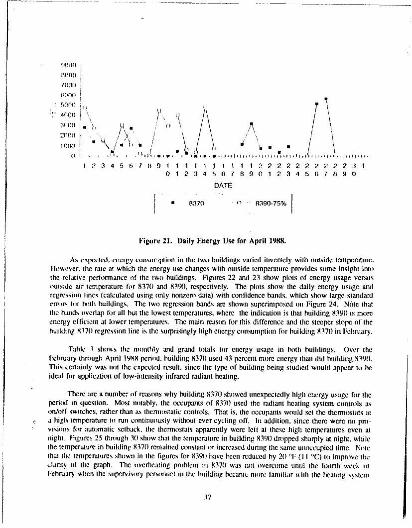
21 Daily Energy Use for April 1988 37
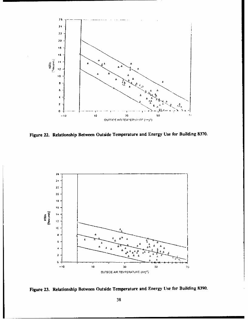
22 Relationship Between Outside Temperature and Energy Use for Building 8370 38
23 Relationship Between Outside Temperature and Energy Use for Building 8390 38
24 Comparison of Response in Energy Use to Variance in Outside Temperature 39
4
FIGURES (Cont'd)
Number Page
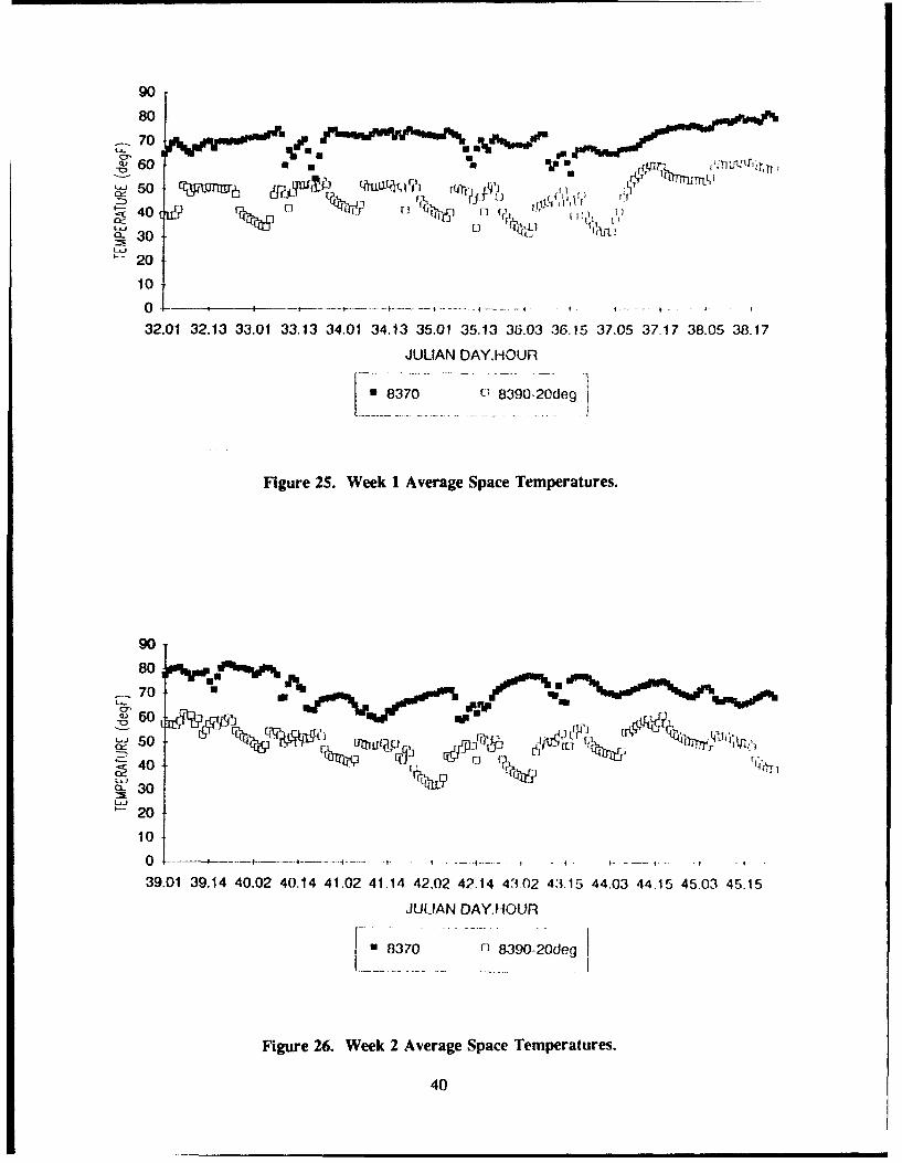
25 Week I Average Space Temperatures 40
26 Week 2 Average Space Temperatures 40
27 Week 3 Average Space Temperatures 41
28 Week 4 Average Space Temperatures 41
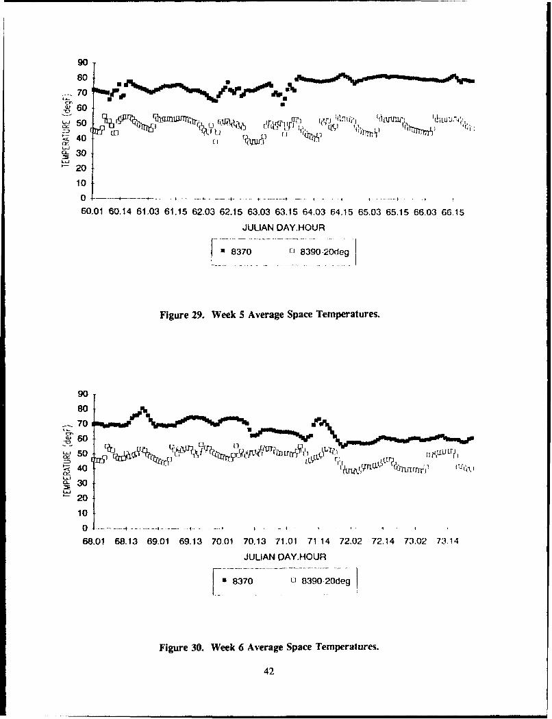
29 Week 5 Average Space Temperatures 42
30 Week 6 Average Space Temperatures 42
31 Bay Doors Percentage Time Open, February 1988 44
32 Bay Doors Percentage Time Open, March 1988 44
33 Bay Doors Percentage Time Open, April 1988 45
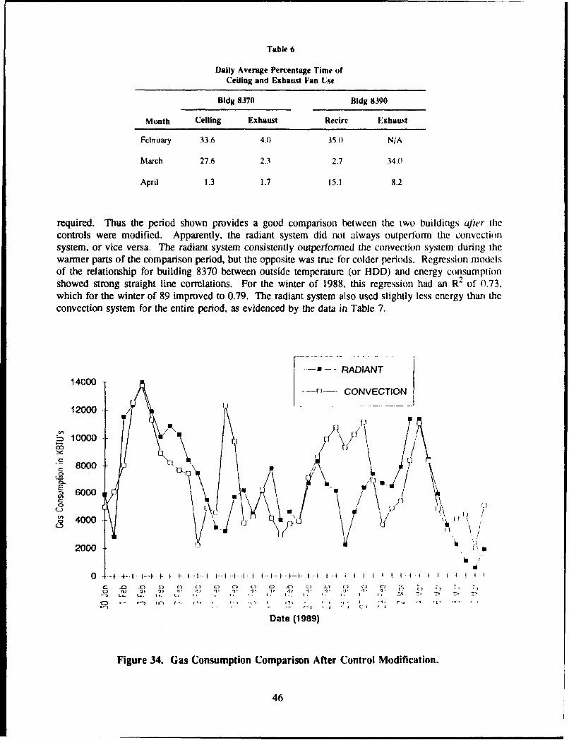
34 Gas Consumption Comparison After Control Modification 46
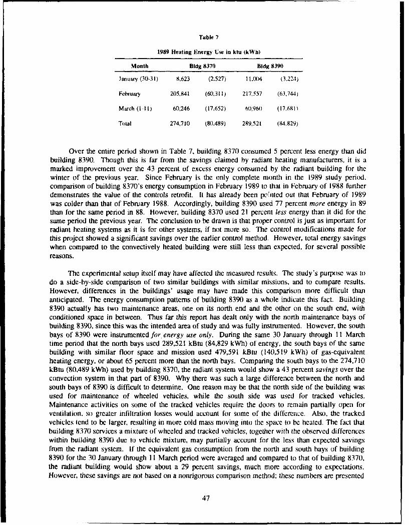
35 Air Stratification for Building 8370, February 1988 5(0
36 Air Stratification for Building 8370, March 1988 50
37 Air Stratification for Building 8370, April 1988 51
38 Air Stratification for Building 8390, February 1988 51
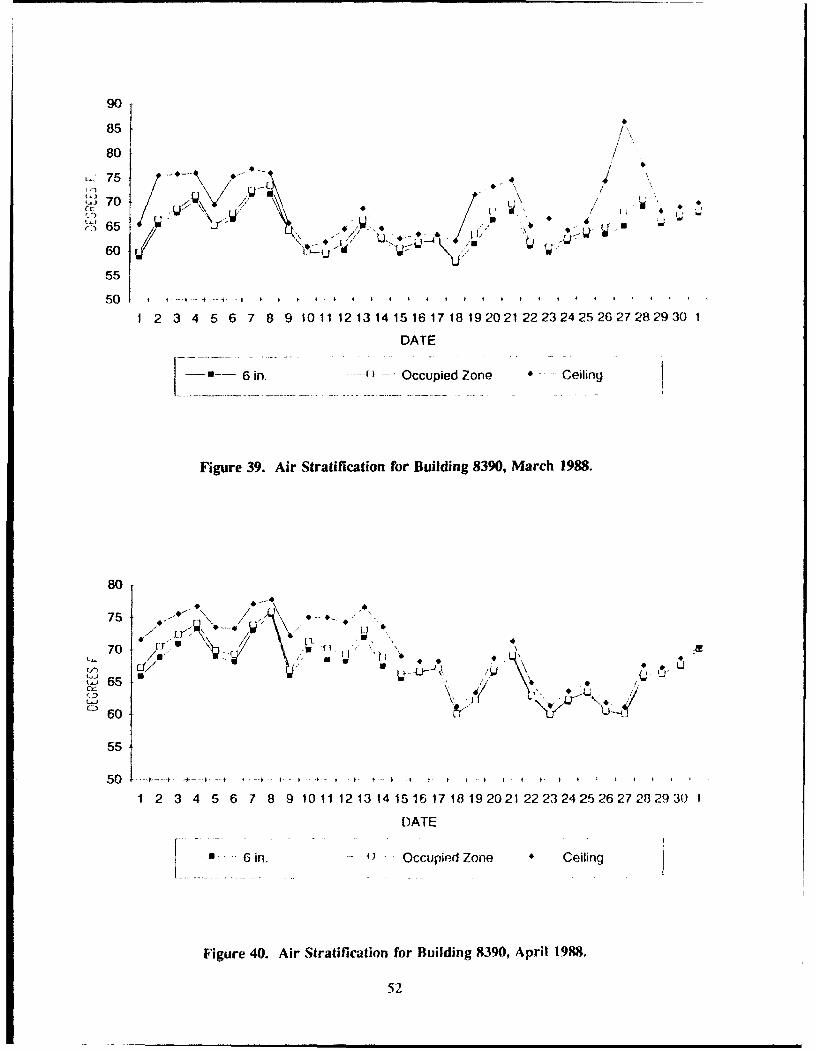
39 Air Stratification Ior Building 8390, March 1988 52
40 Air Stratification for Building 8390, April 1988 52
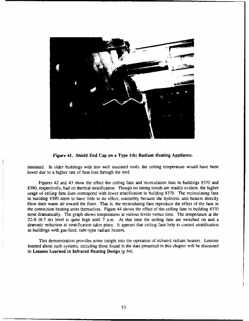
41 Shield End Cap on a Type I(b) Radiant Healing Appliance 53
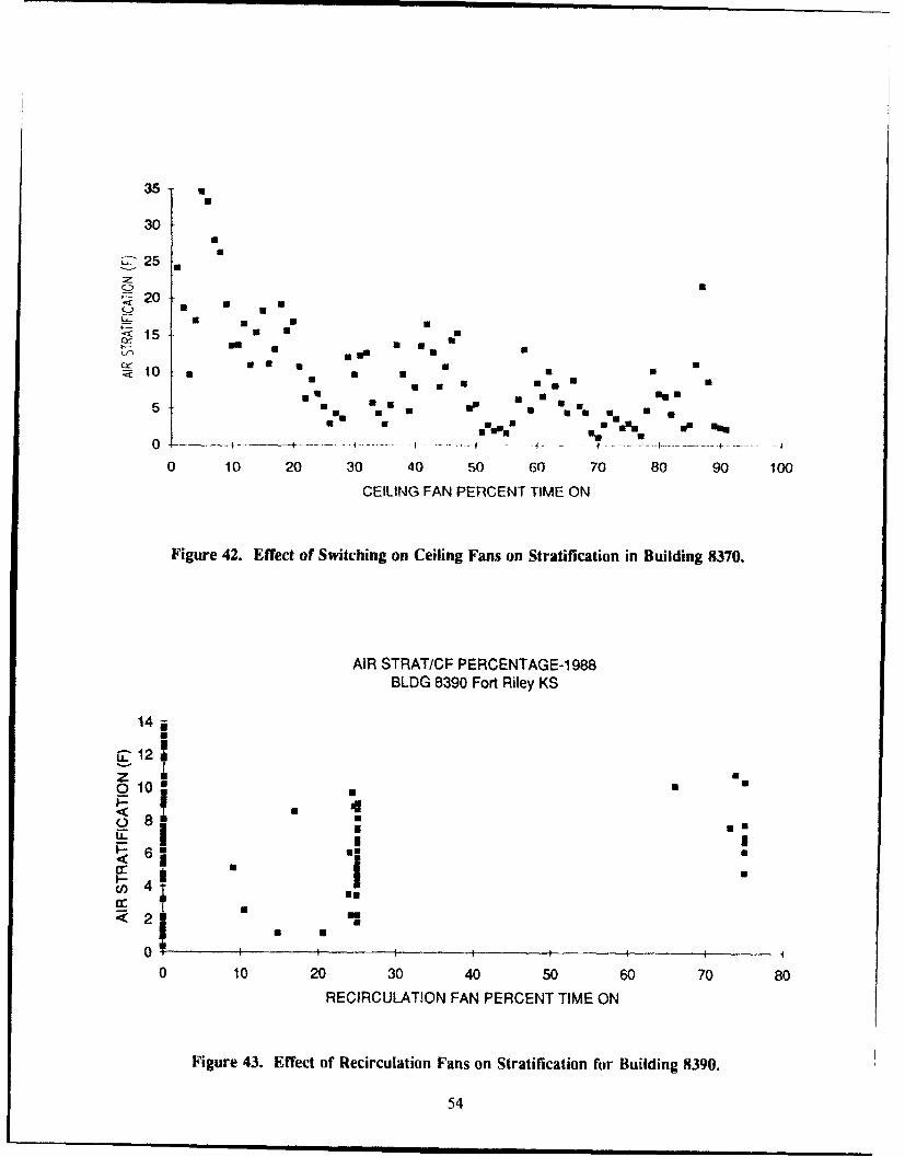
42 E-Iledct o1 Switching on Ceiling Fans oil Stratification in Building 8370 54
43 Ellect of Recirculation Fans oi Stratificalion for Building 8390 54
44 Elfect of Switching on Ceiling Fans on Stratification in Building 8370 55
TABLES
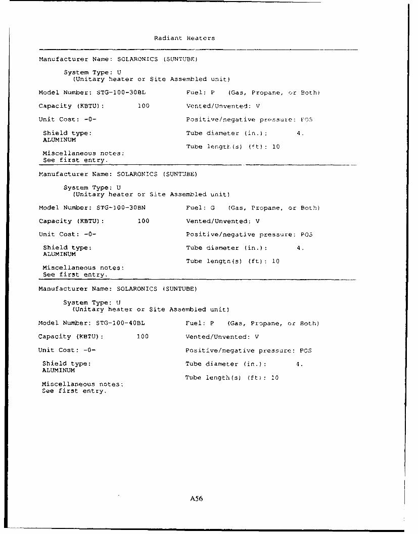
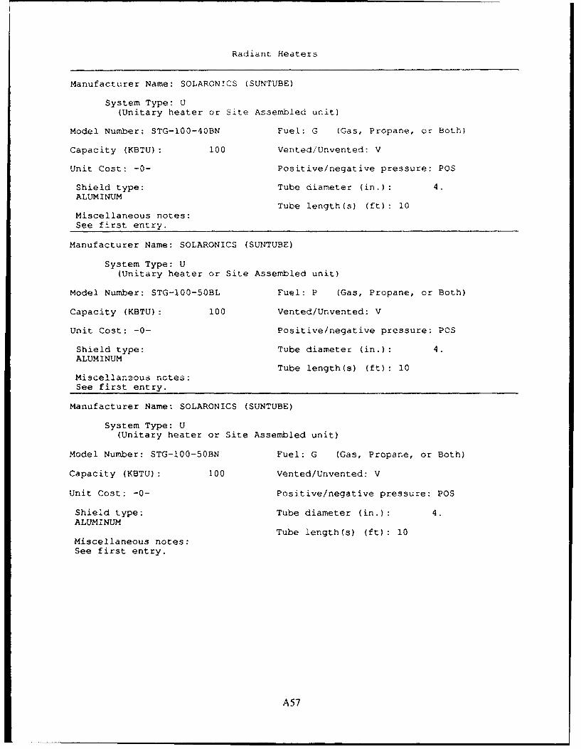
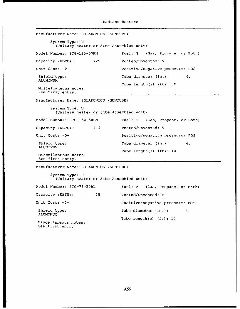
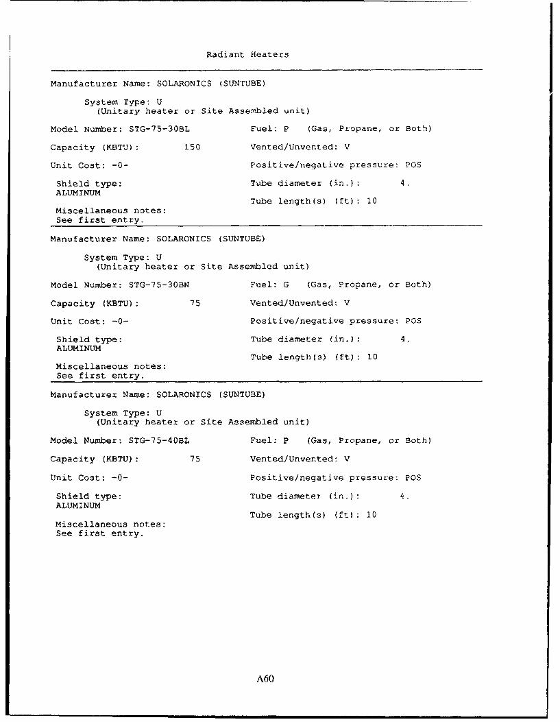
I Gas-Fired Infrared Tube Heating Appliance Manufacturers 20
2 U-Values of Building Components 22
5
TABLES (Cont'd)
Number Page
3 Total 1988 Heating Energy Use in kBtu (kWh) 19
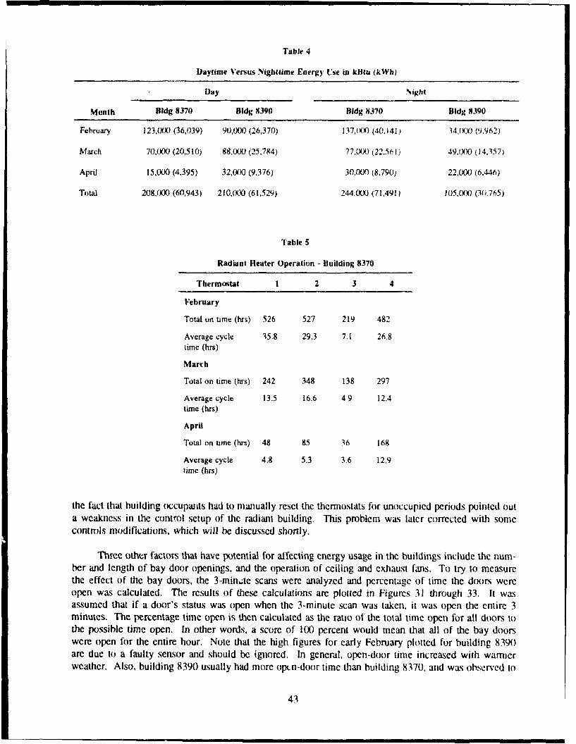
4 Daytime Versus Nighttime Energy Use in kBtu (kWh) 41
5 Radiant Heater Operation - Building 8370 43
6 Daily Average Percentage Time of Ceiling and Exhaust Fan Use 46
7 1989 Heatinig Energy Use in ktu (kWh) 47
8 Thermal Environment Analysis 4X
6
ISSUES IN THE DESIGN OF INFRARED RADIANT HEATING SYSTEMS
I INTRODUCTION
Background
Radiant heating is an ancient form of supplying heat lor human colm(ort. Earliest fornns were
camnp lires used for comfort, cooking, and security. Today, we have a m(ore sophisticated infraredheating supply with many of the same principles.
Radiation is an important component in maintaining human comltor, though air temperature isusually used as the basic indicator of human comfort. In the 1970s and 1980s, infrared heaters werewidely introduced into Army buildings to take advantage of their energy ccnservation potential. Often,this heating source was introduced at the end of building design as part of Value Engineering.' Radiantsystems may require less maintenance, have lower first costs, and have been advertised as more energyconserving than conventional heating systems.
Though operations and maintenance personnel at the Army installations were pleased with radiantsystems, designers felt that the energy conservation benefits of radiant systems had not been proven.Thus, an investigation was undertaken by the U.S. Army Construction Engineering Research Laborato-ries (USACERL) under the Facilities Technology Applications Test (FTAT. now known as the FacilitiesEngineering Applications Program JFEAPJ) program. This investigation looked at facilities at FortRiley, KS which had both conventional heating and radiant heating systems.
This report focuses on gas-fired indirect infrared radiation units, parlicularly tube-type appliances.This restriclion applies since mos;t of this research is based upon a multiyear field lest of these types otunits at Fort Riley. The Fort Riley investigation uncovered several operational issues, revealing thatlittle design guidance was issued from Army sources to their designers. A Research. Development. Test.and Evaluation (RDT&E) work unit was formed to further investigate how designers should analyie andspecify radiant systems.
Objectives
The objectives of this project were to explore the energy conservation possibilities of radiantheating systems in Army applications and to produce a lessons learned document that would recommenddesign guidance for applytng radiant systems.
Approach
The work progressed throuth the following steps:
I. Army installations were surveyed to identify places where radiant systems had been appliedand where possible comparisons between radiant and conventional systems might be monitored.
"Value Engineenng is a pr)gram that rewards contractors for approved suggestions that lower costs Ot operational expcnditures.
7
2. Fort Riley. KS, was selected as the site for the field test.
3. Using two nearly identical buildings, one with a conventional hcalim-1 i ,yICln anid one willh aradiant system. automated data collleccion C(I.liplielln W.LS isiiallcd ill Ca&h hu•hlinl' 1") r dcolo JgivjjC1i 1.1energy consumption. and therimal environment building dynaonics paranictcr', (air lenlr•hralurc'. airvel• city, dew point temperature. globe ihennnctlecr lenperature, tanii/do)or ',Ia.i u*. aic \,Iiahli Ialt• nIcmperatures, awd total energy colnsuipti1(n).
4. Starting in the winter ol 1997-198X. 3-minute and hourly cieigy usc data w(ere codlccicd Irom
the two buildings.
5. Observations of correctable operational measures were observed, chwiged. and luriliercollection was done in the winter )f1 1988-19,9.
6. In fiscal year 1991 (FY91), the RDT&E work unit was funded fr I )ycar to iuncrporate hoththe lessons learned from the field test and current design practices.
Scope
This report is not itself a design guide. However, it does (brnn|late preliminary design le'.snns ,h,:icould later be used in creating a specific guidance for radiant heating syslems,
Mode or Technology Transfer
Information from this study will be put in a Facilities Engineering Applicaiiois fProgran 0-F l--\)decision paper, published in the DEH Digest, and disseminated through Energy Aarcss ScuiiuiarsDesign informatiotn will be distinbuted in the Engineering Improivrnepi Re( ninendfltiftls Sý.%%tcm tFI -II3;Bailetin.
8
-P2 IRINCIPILES OF INFRAREI) RAI)IANT llEATIN(;
Hlistory of Radiant Heating
RatIII.IIt heallill', in v;iriosii lonaIs. hias teI tisied loIr t t(e ijer , T ,li l siplcst lii v•Il i t, lamitirfir uepll Thv.l alcietlit R•maItfnhlCs devised a mIitei sNI ilhisl :lvld oloitr (I1 radianti! UIcatlit, by hi•rti' i 1111igases Iri•ni a lireplace thr•urh ,a channel under lite 11i x r lxblr Ire ii i ring Irmo a slatk uim lit opil•"itl ,iduloi thl liuihliing, hnirared radianit heating is a much li'•irv rect'l developimtuil Tihe infrared band (tdleciori mta.hnoeic radiationll was discovered ill 19(y) fby ithe h~lnglish astr•lnli•mer Sit William Iflerschel, vh(i
tuse-,d a thternil•inmetetr to nmeasunre the heat givent o•1 by each pall of the spectrlitim wihen suinlitihl is dill us'dIrolm a pImns. lie disclvered that Ihe blue prtrl of tlte spectruim ifered the least heat, and that lietelnimpralure rose as lie moved to the red pan of the spectrumn. The highest temperature is actuallyreached past Ihe red part o• ite spei•tinm (the infrared hand).
"Theory regarding high temperature surfaces or catalytic combustion for heat transfer was firstde'eh'ped by two Englishmen in the early 19(X)s. Professor W.A. Bone developed a theory forflarneless inicandescent surface combustion, and H.11. Gray reviewed this theory and presented onie ol hisown. Technical development of systems based on surface combustion theory reached a peak in 1917when 14 patents were issded for such devices.' Interest in the field tapered off until after World Wari[L when research rebounded. In 1956 Guenther Schwank developed a porous ceramic infrared burner,which was licensed to anl American manufacturer. anl(J many new manufacturers of infrared burnersappeared.2 At about that samne time, another U.S. company, Roberts-Gordon. pioneered the concept ofgas.-fired inlraicd radiant tube healers.i Over a 15-year period from about 1953 to 1969. the number olmanuf acturers producing inlrared heaters for building healing increased from one to a total (f 18.1
Today there are Icwcr than 18 manufacturers of infrared radiant lube heating equipment. The hield olradiant healing is broad, ald even within the namrwer context of infrared radiant heating, there aresignil icaiui subtypes.
"Types or Radiant heat
There are three well known modes of heat transfer. Conduction is the transmission of heatthrough solids via transfer of kinetic energy from molecule to molecule. Convection is the transfer ofheat by mixing one part of a fluid with another. If the mixing is entirely due to a difference of densityin the Iluid masses because of a dilference in temperature, the phenomenon is called natural convection.
11 the Illlion ll'f the fluid is caused by mechanical means, it is called forced convection. Radiation isthe transfer of heat via electromagnetic waves emitted by any hot body. Heat transfer by radiationdilfers fronm that of convection and conduction in that matter is not required as a heat transfer medium.The transfer ol heat is direct, from the high temperature body to the lower temperature lbody, eventhrough a vacuum. When the radiation hits the lower temperature body, the energy from the wavecauses a rise in temperature ol the absorbing body through all increase in miolecular activity.
t).W DtWtirh. Literature Reiew i] Infra-red Energy I'rodili'ed With Gais Iurnr'r.N. Rtinsearcth Rullclin 83 (Aucemtwan (;a%As,,ciatiorn Laoratoiries, May 196)1, p I1"t).W DeWcrth, p 2.
3 RklwmrtsGnrdin. In•- Sir Wint Ite,•h'ie Infrared lhandhnak (Kohhcrts-GCordon, tni. Ruflaio, NY, 1990)), p I1 Fied J PrinVIe, "Infrared Healing for Overall Comfort," ASUIRAE Journal (American Society tit ltcating., Rctrigurating and
Air Conitllininng Enginc.is IASHRAEI. Atlania, GA, December 1968), p 57.
t}
Radiant heating is then any form of heating where the dorminant mondwe A heal tra•i.scr is hý rdliation. Conduction and convection still play important roiles in spac:es where radianto hcating i', cmplhJyctI,but they are secondary modes of heat transfer in such systems. Radiant heating Sxstetns may tv hraullycategorized into three types. Low temperature or panel systems operate in the tcnmperature range Itrril120 OF (49 OC) to 350 OF ( 177 OC). Medium temperature or low intensity sslctms kpcrate ini the 5M0 4(260 °C) to 1500 OF (816 OC) range. High temperature or medium to high intensity systcms ()pcrale attemperatures abovc 15(X) IF (816 'C). High temperature radiant heating units are generally opln flamedevices, often with incandescent ceramic faces. Medium temperature units oiperale bchlw inicandcscenttemperatures. and are generally indirect fired units, such as those with heated tube emitters. lowtemperature radiant heating is typically done with large heated surfaces, often lotors, or wall or ceilingpanels. It is imrxtant ito note that the temperature ranges used to delineate these three categorens o)systems will vary front reference to reference. The values given here were selected aS lypital. lo,,bwhile there are various radiant heating systems for industrial applications isuch as dryiing! pronesscs,etc.). this report locuses only oit space-healing applicationis, for which soni typical system lypcs havebeen identified.
Low temperature radiant heating systems typically available for space heating include hydronicfloor panels, electric floor panels, air flours, hydronic ceiling panels, elcctric ceiling panels, hydrnicwall panels, and electric wall panels. Hydronic floor panel systems typically consist of pipes entheddcdin a concrete floor through which heated water is circulated to maintain a maximum floor temperature oIabout 85 IF (29 °C). Hydronic floor panel systems are generally best suited for applications where largechanges in heating load do not occur over a short time since transient responses are slow due it) thethermal mass of the floor. Electric floor panels have the same operating characteristics and applicationas hydronic floor panels, only instead of water in pipes to provide the heat. electric heating elemcnt.s areused to heat the floor. Air floors use a third method to provide heat to the floor, that o(f circulatingheated air from a furnace through passageways in the floor. The surface temperatures are the same asthose for other floor systems, and transient response is still slow. Hydronic ceiling panels may heexposed modular metal panels laid in or suspended from the ceiling, or they may he tubing attached tothe ceiling and covered with plaster. Hot water is circulated through the panels it produce a surfacetemperature between 120 IF (49 °C) and 180 OF (82 °C). The transient response titne (Or hydronic ceil-ing panel systems is much shorter, so they may be used in applications where rapid load changes in thespace are encountered. Electric ceiling panels are composed of various types of heaters sandwichedbetween the ceiling surface material and an insulated back on the panel. These systems operate ini thesame temperature range as their hydronic counterparts, and also respond quickly to changes in load inthe space. Hydronic wall panels are constructed similarly to hydronic ceiling panels. Wall panels areused in place of ceiling panels where interference with lighting or other fixtures is a problem. Hydronicwall panels have the same operating characteristics as the ceiling panels, only more heated panel area isrequired than for ceiling panels, and surface temperatures must he limited if there is the possibility ofcontact with people. These same relationships hold true for electric wall panels with respect to theirceiling counterparts.
Medium temperature space heating appliances include gas-fired radiant tube infrared heaters, andsome electric infrared units. Gas-fired radiant tube appliances consist of a combustion chamber where.gas and air are burned and the products of combustion are then forced through a section (f tubing andexhausted to the outdoors. The hot tube provides the radiant energy source (thus the name radiant tube).These units are also fitted with various types of reflectors and/or deflectors to direcl the radiant encrgytoward the floor, and not onto exterior walls or the ceiling. These units may either have a U-shaped orlinear tube, and are operated in on-off fashion. During operation, tube temperatures vary from 5(X) IF(260 IC) to 9(00 °F (482 IC) along the length of the tube. They can adapt rapidly (() changing loads ina space and have a larger radiating surface than other types of gas-fired infrared units. Medium tem-perature electric infrared appliances use panels as their radiant energy source, which have a surface
10
temperature from 200 OF (93 OC) to 1100 'F (593 0C). These units are typically used for direct spotheating of the space occupants, objects, or surfaces.
High temperature units include gas-fired radiant porous refractory surface infrared units and othertypes of electric infrared units. The gas-fired radiant porous refractory surface infrared appliances burna mixture of air and gas through a porous refractory material to produce the high temperature radiantenergy source. These units are unvented, so the products of combustion arc placed in the space beingheated. Some units include focusing devices to direct the heat to particular locations at a higher inten-sity. These units operate in a temperature range from 15(X) OF (816 °C) to 2(XX) 'F (1094 'C). Electricinfrared units use metal rods, quartz tubes, or quartz lamps as their source of radiant energy. Metal rodand quartz tube units operate at surface temperatures between 15(X) OF (816 'C) and 18(X) OF (982 'C).Quartz lamps operate at a surface temperature of about 4W0() OF (2204 °C). Both the gas-fired and elec-tric units of this type are designed for space heating applications in large volumes where only thepeople, objects, and surfaces to be heated receive radiant energy (spot heating). Such units provide heatinstantly when called upon to heat an occupant or object in their area of coverage.
Gas-fired infrared heating appliances operate in the medium and high temperature range. Gas-tiredinfrared units are generally considered to be either high intensity or low intensity appliances, thedistincton being the temperature range in which the radiation source is operated (above or below incan-descence, respectively). In many respects, this method of classification is unfortunate. For example.some practitioners will call any infrared application "high intensity" without indicating whether they arereferring to "radiant" systems in general or "infrared" systems. While it may be true that tube-typeheaters deliver more intense heat energy than do heated floor slabs, they are still low intensity infraredheaters. In the absence of better definitions, caution should be used when reviewing literature on radiantheating applications, as there is much inconsistent use of terminology.
The American Society of Heating, Refrigerating and Air-Conditioning Engineers (ASHRAE) hasoutlined three specific types of gas-fired infrared heaters: 5
i. Indirect infrared radiation units, or indirect fired units, or Type 1 units for short. These unitsbum a gas-air mixture within the radiating elements and have a radiating surface interposed between thecombustion products and the load. Operation temperatures are up to 1200 OF (650 °C). The units maybe comprised of tubes or panels, and they may have metal or ceramic components. Type 1 units can befurther classified into three subtypes. Type l(a) units are those that have an atmospheric burner andvent combustion products through a vertical flue arrangement. Type l(b) units may have multipleburners possibly with eductors operating in a horizontal tube arrangeme.nt. Type i(c) units use a singleforced draft burner, also in a horizontal tube. Type I units are usually vented (i.e., the combustionproducts are not released to the space).
2. Porous matrix infrared radiation units, or direct-fired (or Type 2) units bum a gas-air mixturein a refractory material, which may be porous ceramic, drilled port ceramic, stainless steel, or a metallicscreen. This refractory is in an enclosure with an open face exposing the refractory to the load. Thegas-air mixture is brought into the enclosure and through the refractory where it is burned. Due to theporous nature of the refractory, combustion is even across its face. The flame on the surface of andreceding into the refractory material heats it, thus providing the radiant energy source.
3. Catalytic oxidation infrared radiant units, or simply catalytic (or Type 3) units are similar tothe direct-fired units. The major difference is that the refractory material is usually glass wool and the
radiation source is a catalyst that induces oxidation without a visible flainc. Figure I illustrates thevarious types of infrared radiant heaters as defined by ASHRAE.
There are distinctions to be made beyond the ASHRAE classifications of indirect-fired (Type 1)units. For example, Roberts-Gordon asserts that the ASHRAE infrared heating appliance types do niotadequately reflect the products that have come to the market place. '1The result is that the industry hismoved beyond these definitions by introducing new appliances that fall into more than one of these cate-gories. In addition, ASHRAE has not yet developed a way for the cngi iccring community to dJistinguishbetween appliancc performances within a category or between categories. -hThe problemY lies ini thefine distinction between Type 1(b) and Type 1(c) appliances.
The ASHRAE specification states that Type 1(b) appliances are usually vented and may requireeductors (e.g., vacuum pumps to evacuate the exhaust). Some indirect-tired tube type units are installedwithout being vented, that is, they exhaust to the interior space. Also, the ASH-RAE classificationscheme makes no distinction between the type of eductor used. While some Type 1 (b) units use vacuumpumps to evacuate combustion products, most Type 1(h) and 1(c) units do not use a vacuum assist, but
EXHAUST -N)~tr
'HAMUfR
RADIANTV.REFLECTOR-.. TUBE
RAO)AT1P40 ~ASSEMBLIES *tEON
TU'4E
INTANE ~ ~ ~ ~ .%IA VACUM PUMJP fIg - AP't
INTAKE I ~~~EXHAUST SISy- API
IN) INOIPECT 4.4 MEATIER ftpj tNGIPFCT TUNE TyPE HPATFfl iý) ,,IQTl( TVPIE T PE ,IEATFOIVAC-UUA O)PEPA1FPI rnn'ýEO r)DA~rl
TYP 2 TYEw I
Ai NISIJI A IGN "A., -..- ' .. ; .n,'
111 1A~At " PAD, - T A'1''~ SI*
'Ori'OUn rfaALV'q P~PAlIV
SLISWAME COBOUST" AI
(IS PONOIJ MATRIN I INl 8UMM0ES $.I ATAtY TIC ON IIDATIIN I Q BRIANIF S
Figure 1. Types of Gas-Fired Heaters. (Reprinted with permission from the American Society ofHeating, Refrigerating and Air-Conditioning Engineers, from the 1988 ASHRAE Hand-book - Equipment.)
6 Roberts-Gordon, Inc., p 12.
12
rather arc forced draft systems. In addition, no distinction is made in the ASHRAE scheme as to theexiting condition of the exhaust gases. Some appliances exhaust at a lower temperature such that thereis condensate in the exhaust products (condensing units). Other units do not have a sufficient run ofradiant piping for the gases tI cool and are noncondensing units. A condensing unit will have a highercombustion efficiency than a noncondensing unit by virtue of its lower stack losses. Generally, TypeI(b) appliances are thought of as condensing, and Type l(c) are thought of as noncondensing. Anotherdistinction between the two types is implied by the ASHRAE drawing but niot stated in the text. Thatdistinction is that type t(b) units use multiple burners in a run of tube and arc site assembled, whcrea.sType 1(c) units use one burner on a set length of tube that is all factory assemnbled. However, producLscurrently exist in the marketplace that are a hybrid of these two types. For example, multiple units thatwould be considered Type I(c) in that they do not have multiple burners and are noncondensing may befield assembled on a common exhaust. This arrangement is less efficient than a Type I(b) system withmultiple burners, having an efficiency more like a Type l(c) unit. However, this arrangement can beinstalled instead of the desired Type 1(b) system it contract specifications are not carefully or clearlywritten. Also, multiple burner appliances can be non-condensing units, lower in combustion efficiencythan other condensing multiple burner units. Other variances in market offerings exist that are notreadily delineated by the ASHRAE classification scheme. This discussion does not imply that theASHRAE classification is not useful, only that it is not all-inclusive and that the potential user ofinfrared heating products should look further before making decisions.
Theory of Operation of Low-Intensity Infrared Heaters
The operation of infrared radiant heaters can be described in terms of physical equations, most ofwhich are well known. Infrared radiation differs in no way from other forms of electromagnetic wavesexcept for wavelength. For all forms of electromagnetic radiation including l ight and infrared waves, therelationship between velocity, frequency, and wavelength is given as:
c =f'% IEq I1
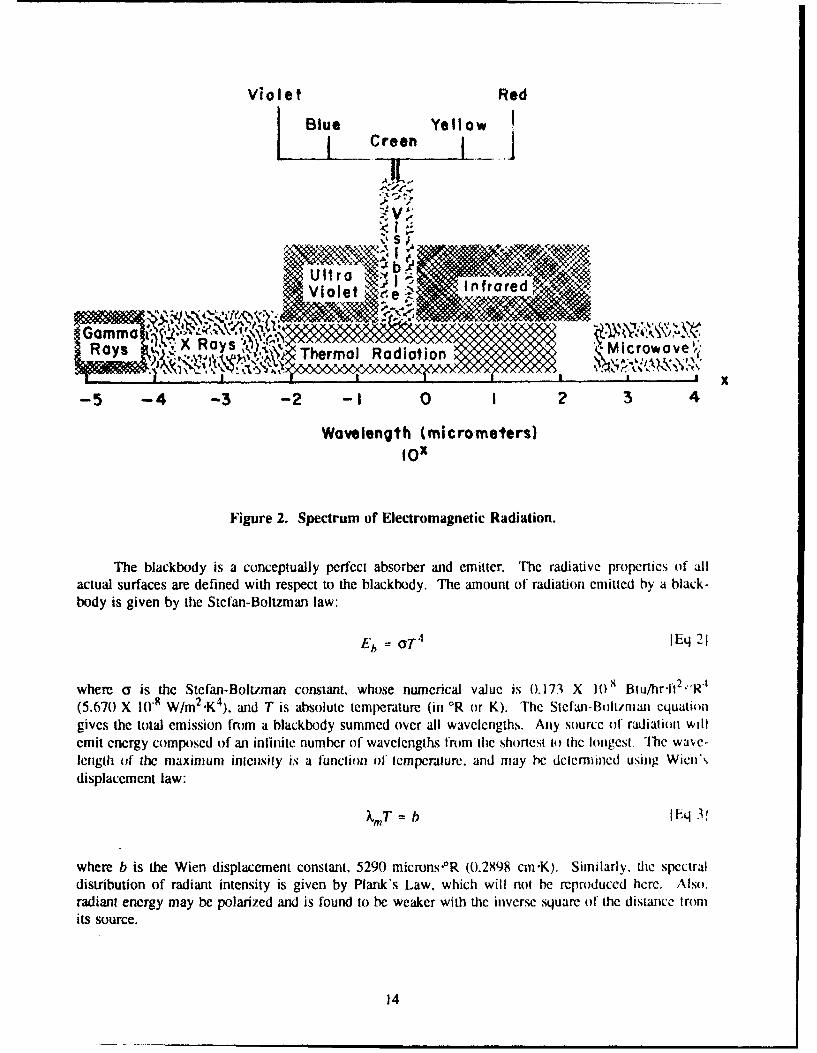
where f denotes frequency, ? denotes wavelength, and c is the velocity of light, a constant (186,M)mi/sec or 2.998 X 10⁸ m/s). Infrared radiation is defined as the band of radiation between the frequen-cies of 0.7 micrometers (pm) to 400 pm. This band is sometimes further subdivided in the literature intonear infrared radiation (0.7 to 2.7 pm) and far infrared radiation (2.7 W to 40() pm). Figure 2 illustratesthe relationship to wavelength of various forms of electromagnetic radiation.
When heat transfer by radiation is considered, the derivation of the physical equations is basedupon the principle of a blackbody. A blackbody is an ideal surface with the following properties:
1. A blackbhody absorbs all radiation incident upon it.2. For a given temperature and wavelength, no surface can emit more energy than a blackbody.3. The blackb'ody is a diffuse emitter. That is, radiation emitted by the blackbody is independent
of direction.7
7 F.P. Incropera and D,11. DeWitt. Fundamentals of tteat Transfer (John Wiley and Sons. New York. 1981), p 557.
13
Violet Red
Blue YellowCreen j
p b
-5 .-4 -3 -2 - I 0 I 2 3 4
Wovelength (micrometers)'Ox
Figure 2. Spectrum or Electromagnetic Radiation.
The blackbody is a conceptually perfect absorber and emitter. The radiative properties of allactual surfaces are defined with respect to the blackbody. The amount of radiation emitted by a black-body is given by the Stefan-Boltzman law:
Eb = aT 4 IEq 21
where a is the Stefan-Boltman constant, whose numerical value is 0.173 X 10 Btu/hr'lt2 ""R-(5.670 X 10.8 W/m 2.K4), and T is absolute temperature (in 'R or K). The Stlcan-Boltitmal cquationgives the total emission from a blackbody summed over all wavelengths. Any source o1 radiation willemit energy composed of an inlinite number of wavelengths from the shortest to the longest. The wa.c-length (of the maximum intensity is a function of temperalure, and may he delermijcd using Wicn'sdisplacement law:
XmT = b I -q 3 f
where b is the Wien displacement constant, 5290 microns.°R (0.2898 cm.K). Similarly, the spectraldistribution of radiant intensity is given by Plank's Law, which will not be reproduced here. Also.radiant energy may be polarized and is found to be weaker with the inverse ,square of the distance fromits source.
14
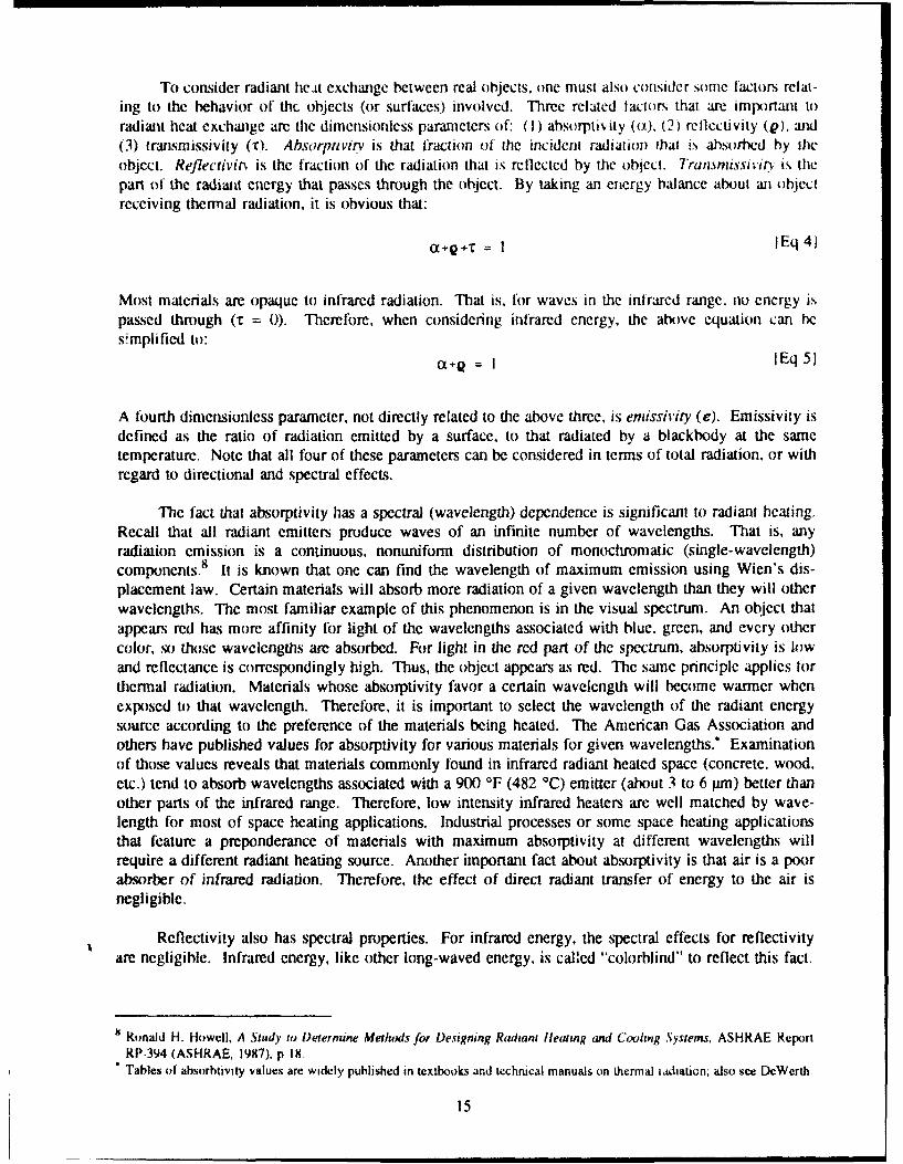
To consider radiant he4t exchange between real objects, one must also consider some factors relat-ing to the behavior of the objects (or surfaces) involved. Three related factors that are important toradiant heat exchange are the dimensionless parameters of: (1) absorptiviiy (o), (2) rellectivity (p). and(3) transmissivity ('r). Absorptivirv is that fraction of the incident radiation that is absorbed by Iheobject. Reflectivit% is the fraction of the radiation that is reflected by the object. TransmisstvitA is thepart of the radiant energy that passes through the object. By taking an energy balance about an objectreceiving thermal radiation, it is obvious that:
(L+Q+t 1 Eq 41
Most materials are opaque to infrared radiation. That is, for waves in the infrared range. no energy ispassed through (t = 0). Therefore, when considering infrared energy, the above equation can besimplified to:
t+Q I Eq 51
A fourth dimensionless parameter. not directly related to the above three, is ernissivity (e). Emissivity isdefined as the ratio of radiation emitted by a surface, to that radiated by a blackbody at the sametemperature. Note that all four of these parameters can be considered in terms of total radiation, or withregard to directional and spectral effects.
The fact that absorptivity has a spectral (wavelength) dependence is significant to radiant heating.Recall that all radiant emitters produce waves of an infinite number of wavelengths. That is, anyradiation emission is a continuous, nonuniform distribution of monochromatic (single-wavelength)components.8 It is known that one can find the wavelength of maximum emission using Wien's dis-placement law. Certain materials will absorb more radiation of a given wavelength than they will otherwavelengths. The most familiar example of this phenomenon is in the visual spectrum. An object thatappears red has more affinity for light of the wavelengths associated with blue. green, and every othercolor, so those wavelengths are absorbed. For light in the red part of the spectrum, absorptivity is lowand reflectance is correspondingly high. Thus, the object appears as red. The same principle applies forthermal radiation. Materials whose absorptivity favor a certain wavelength will become warmer whenexposed to that wavelength. Therefore, it is important to select the wavelength of the radiant energysource according to the preference of the materials being heated. The American Gas Association andothers have published values for absorptivity for various materials for given wavelengths. Examinationof those values reveals that materials commonly found in infrared radiant heated space (concrete, wood.etc.) tend to absorb wavelengths associated with a 900 'F (482 °C) emitter (about 3 to 6 pm) better thanother parts of the infrared range. Therefore, low intensity infrared heaters are well matched by wave-length for most of space heating applications. Industrial processes or some space heating applicationsthat feature a preponderance of materials with maximum absorptivity at different wavelengths willrequire a different radiant heating source. Another important fact about absorptivity is that air is a poorabsorber of infrared radiation. Therefore, the effect of direct radiant transfer of energy to the air isnegligible.
Reflectivity also has spectral properties. For infrared energy, the spectral effects for reflectivityare negligible. Infrared energy, like other long-waved energy, is called "colorblind" to reflect this fact.
SRonald H. Howell. A Study to Determine Methods for Designing Radiant IHeatig and Coohng Systems. ASHRAE ReportRP-394 (ASHRAE, 1987). p 18."Tables of absorbtivity values are widely published in textbooks and technical manuals on thermal iadiation. also see DeWerth
15
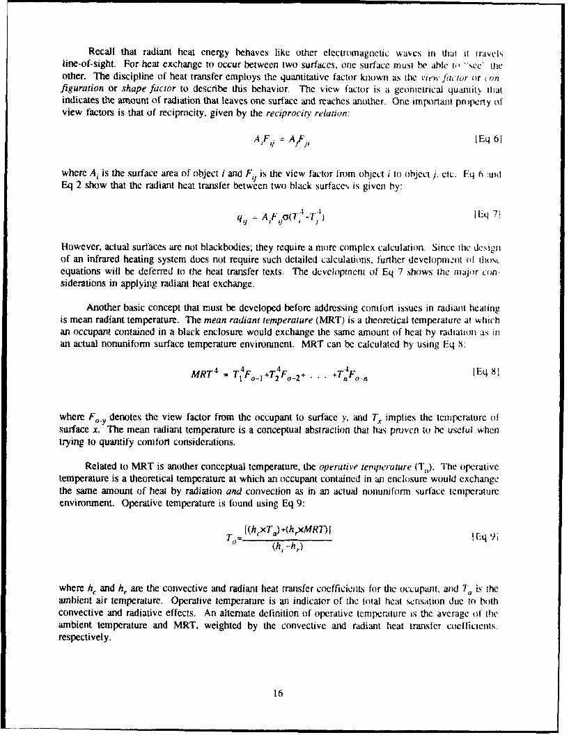
Recall that radiant heat energy behaves like other electromagnetic waves in (hat it travelsline-of-sight. For heat exchange to occur between two surfaces, one surface must be able iw "see' theother. The discipline of heat transfer employs the quantitative factor known as the view fitcior or (onfiguration or shape factor to describe this behavior. The view factor is a geometrical quantity thatindicates the amount of radiation that leaves one surface and reaches another. One imponant property ofview factors is that of reciprocity, given by the reciprocity relation:
AF I A IEq 61
where Ai is the surface area of object i and FI is the view factor from object i to object j, etc. Eq 6 :un]Eq 2 show that the radiant heat transfer between two black surfaces is given by:
q, A,/,aO(7, -T1 ) ILAI 71
However, actual surfaces are not blackbodies; they require a more complex calculation. Since the designof an infrared heating system does not require such detailed calculatidons, further development ol thostequations will be deferred to the heat transfer texts. The development of Eq 7 shows the major con-siderations in applying radiant heat exchange.
Another basic concept that must be developed before addressing comfort issues in radiant heatingis mean radiant temperature. The mean radiant temperature (MRT) is a theoretical temperature at whichan occupant contained in a black enclosure would exchange the same amount of heat by radiation as inan actual nonuniform surface temperature environment. MRT can be calculated by using Eq S:
R4 4 4 4 1E ,MRT = =TFo_ +T2 Fo_2+ . +T,• F li
where Fo0 y denotes the view factor from the occupant to surface y, and T. implies the temperature ofsurface x. The mean radiant temperature is a conceptual abstraction that has proven to be useful whentrying to quantify comforl considerations.
Related to MRT is another conceptual temperature, the operative temperature (TO). The operativetemperature is a theoretical temperature at which an occupant contained in an enclosure would exchangethe same amount of heat by radiation and convection as in an actual nonuniform surface temperatureenvironment. Operative temperature is found using Eq 9:
T= [(hcXTa) (hr×MRT)I I Eq 9,(h,-hr)
where h. and hr are the convective and radiant heat transfer coefficicnts for the occupant, and 7, is theambient air temperature. Operative temperature is an indicator of the total heat sensation due to bothconvective and radiative effects. An alternate definition of operative temperature is the average of theambient temperature and MRT, weighted by the convective and radiant heat transfer coefficients,respectively.
16
As is the goal with any space heating system, infrared radiant heating systems seek to providecomfort. How to quantify comfort is still somewhat of an open question in facility engineering to date.The Fangcr Comfort Equations9 are based upon the notion that comfort is defined by a state of neutraltemperature sensation. Four principal environmental parameters help determine comfort conditions:(1) the ambient air temperature (Ta). (2) relative humidity (RH), (3) relative air velocity (V), and (4)MRT. Two other comfort parameters relate to the occupant as well: the metabolic rate for persons attheir given activity level (MET), and the thermal resistance of the clothing they are wearing (CLO)Comfort models and their applications are not straightforward. In general. for a given activity level andclothing weight, the air temperature (Ta) required for comfort goes down as the MRT increases. 10This relation is of particular interest when considering radiant heating options.
9 P.O. Fanger, Thernal Comfort (McGraw-Hill, New York, 1972).10 ASHRAE Handbook of Fundamentals (ASHRAE, 1989).
17
3 COMMERCIAL INFRARED HEATERS
Claims Arising From Principles of Operation
It is readily apparent that radiant heating systems operate on a diflorent set of principles fromconvective heating systems. Manufacturers use these differences to highlight purfl)rted advantages ofradiant heating over conventional heating systems. Typical manufacturer's sales literature might tout thefollowing:
* Energy savings Comfort* Lack of stratification Less heat loss* Immediate warmth No dirt and dust particles* Quiet operation Comifort at lower temperatures* Low maintenance Easy installation• Uniform heating Space efficiency.
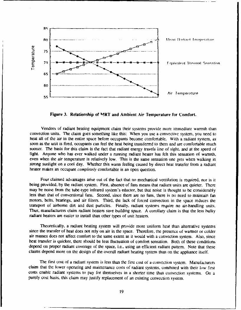
These sales claims are supported by the principles that govern radiant heat trarisfer. The most popularclaim (and sales point) is that of reduced energy consumption over convection systems. Advertising torradiant heating claims as much as a 75 percent savings in energy consumption over convective sysiems.One reason for this claim is that radiant heat can maintain space at comfortable conditions at lower airtemperatures. Recall that to have comfortable conditions with convective heating systems. the air tem-perature and MRT are generally the same.' 1 For a sedentary person wearing medium weight clothing,if the MRT is 80.6 OF (27 °C) then the air temperature should actually be lowered to 72 OF (22 'C) tomaintain comfort (p 31). The corresponding temperature for comfort when air temperature equals theMRT is 76.5 OF (24.7 °C). As the MRT is increased, the corresponding air temperature required forcomfort is further reduced. Figure 3 illustrates this relationship. Lower interior air temperatures implya lower temperature difference between the conditioned space and the ambient air, and thus lower energylosses through the building envelope. That is, transmission losses through the walls are reduced.Another reason that less heat should be lost through the walls is that radiant energy is directed. and willheat only objects within the path of the radiation. Properly installed tube-type infrared heaters arcequipped with reflectors (and/or deflectors) that prevent direct radiation to the walls. These claims oflower heat loss form the basis for claims of energy savings.
Another common claim is that radiant systems eliminate thermal stratification problems. Thermalstratification refers to the situation where the warmest air is at the top ot the building near the ceiling,while cooler air is found at the occupied levels. The argument goes that since warm air rises, convectionsystems are prone to stratification problems. Radiant healer manufacturers claim their systems are muchless prone to this problem because infrared radiation does not heat the air. but rather, the objects at whichthe rays are directed. Since the air is not directly healed, warm air will not rise to the ceiling to cause thestratification effect. There are two direct benefits to reducing stratification. First, the heat remairns whereneeded, at the occupant level, making the heating system more eftective, Second, the temperature at thcroof level is lower, thus reducing losses through the roof. One would expect these claims to be true tosome extent, but it should be remembered that the heated objects in the space will release heat viaconvection, therefore the air in the space is heated by the radiant system, although to a lesser extent.Warm air rises regardless of heating system typc. The stratification question is one of degree.
I Ronald H. Howell, p 31.
18
75
a)
65 -
60
Air Temperalurp55
Figure 3. Relationship of MRT and Ambient Air Temperature for Comfort.
Vendors of radiant heating equipment claim their systems provide more immediate warmth thanconvection units. The claim goes something like this: When you use a convective system, you need toheat all of the air in the entire space before occupants become comfortable. With a radiant system, assoon as the unit is fired, occupants can feel the heat being transferred to them and are comfortable muchsooner. The basis for this claim is the fact that radiant energy travels line of sight, and at the speed oflight. Anyone who has ever walked under a running radiant heater has felt this sensation of warmth,even when the air temperature is relatively low. This is the same sensation one gets when walking instrong sunlight on a cool day. Whether this warm feeling caused by direct heat transfer from a radiantheater makes an occupant completely comfortable is an open question.
Four claimed advantages arise out of the fact that no mechanical ventilation is required, nor is itbeing provided, by the radiant system. First, absence of fans means that radiant units are quieter. Theremay be noise from the tube-type infrared system's eductor, but that noise is thought to be considerablyless than that of conventional fans. Second, since there are no fans, there is no need to maintain fanmotors, belts, bearings, and air filters. Third, the lack of forced convection in the space reduces thetransport of airborne dirt and dust particles. Finally, radiant systems require no air-handling units.Thus, manufacturers claim radiant heaters save building space. A corollary claim is that the less bulkyradiant heaters are easier to install than other types of unit heaters.
Theoretically, a radiant heating system will provide more uniform heat than alternative systemssince the transfer of heat does not rely on air in the space. Therefore, the presence of warmer or colderair masses does not affect comfort to the same extent as it would with a convection system. Also, sinceheat transfer is quicker, there should be less fluctuation of comfort sensation. Both of these conditionsdepend on proper radiant coverage of the space, i.e., using an efficient radiant pattern. Note that theseclaims depend more on the design of the overall radiant heating system than on the appliance itself.
The first cost of a radiant system is less than the first cost of a convection system. Manufacturersclaim that the lower operating and maintenance costs of radiant systems, combined with their low firstcosts enable radiant systems to pay for themselves in a shorter time than convection systems. On apurely cost basis, this claim may justify replacement of an existing convection system.
19
Most manufacturers' claims are based on the theory of hcat transfer. As with any advcrtI,,ingclaims, potential buyers must be wary of oversiated claims. Most marnufacturers can subsalaitiale soi•,cof their claims with experience and data. Such substantiated data must he separated troll) the ,aI>presentation for use in a sound scientific comparison of healing mcthods. This report will imcludeexamples of unbiased data and experience from a multiyear field test.
Current U.S. Manufacturers of Radiant Heating Equipment
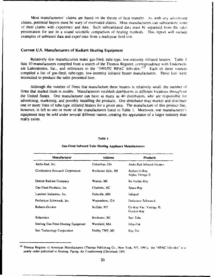
Relatively few manufacturers make gas-fired, tube-type, low-intensity infrared heaters. Table Ilists 10 manufacturers compiled from a search of the Thomas Register, corres x)ndetnce with Uiderwrit-ers Laboratories, Inc., and references to the "1991/92 HPAC Info-dex."]? Each of these sourcescompiled a list of gas-fired, tube-type, low-intensity infrared heater manufacturers. These lists werereconciled to produce the table presented here.
Although the number of firms that manufacture these heaters is relatively small, the number offirms that market them is sizable. Manufacturers establish distributors in different locations throughiouthe United States. One manufacturer can have as many as 40 distributors, who arc reslftnsihle foradvertising, marketing, and possibly installing the products. One distributor may market and distrihuteone or more lines of tube-type infrared heaters for a given area. The manufacture of this product line.however, is left to one or more of the manufacturers listed in Table 1. Moreover, one manulacturer'sequipment may be sold under several different names, creating the appearance of a larger industry thanreally exists.
Ambi-Rad, Inc. Columbus, OH Ambi-Rad Infrared Heaters
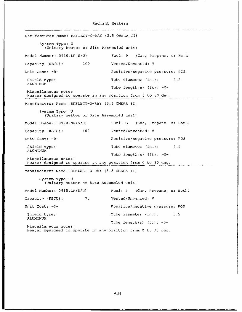
Combustion Research Corporation Rochester Hills, MI Reflect-O-Ray,Alpha, Omega II
Detroit Radiant Company Warren, MI Re-Verber-Ray
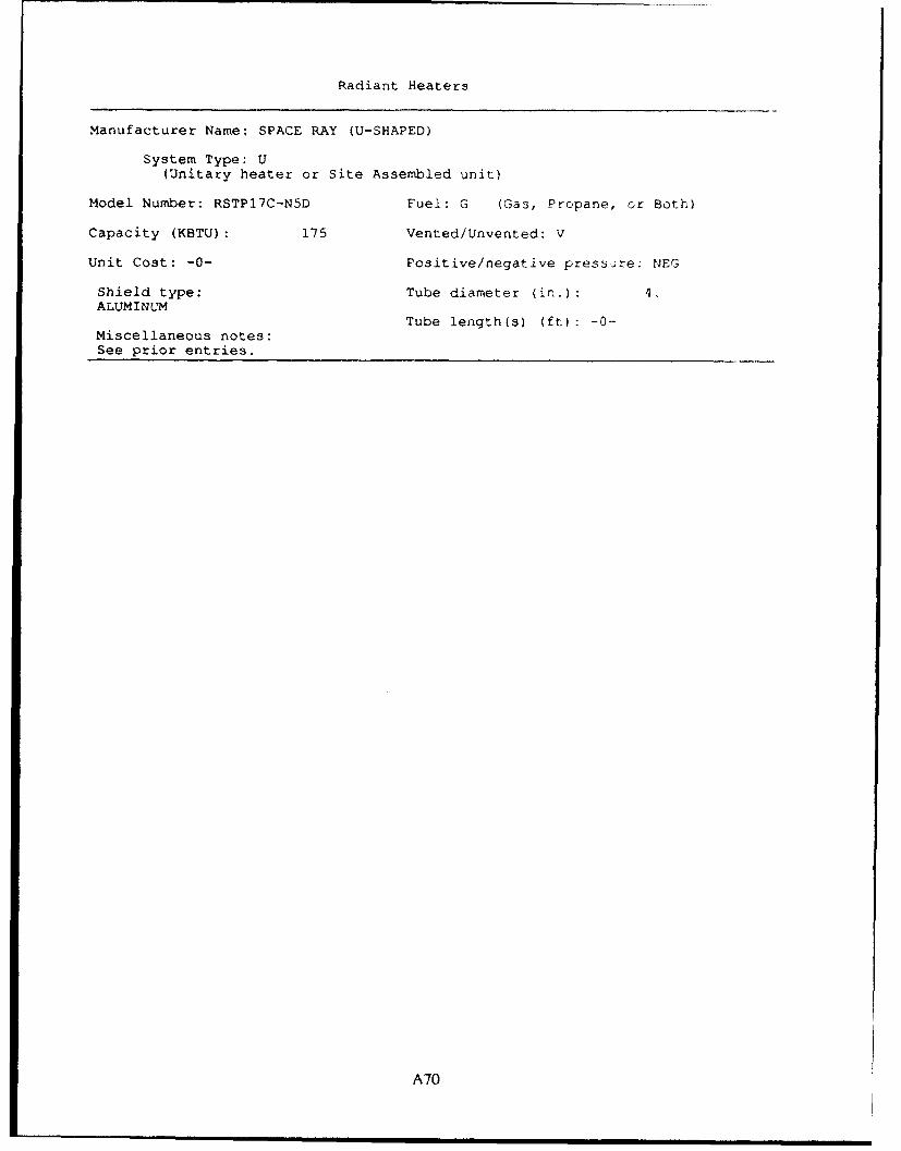
Gas-Fired Products, Inc. Charlotte, NC Space-Ray
Lambert Industries, Inc. Parkville, MN Infrared
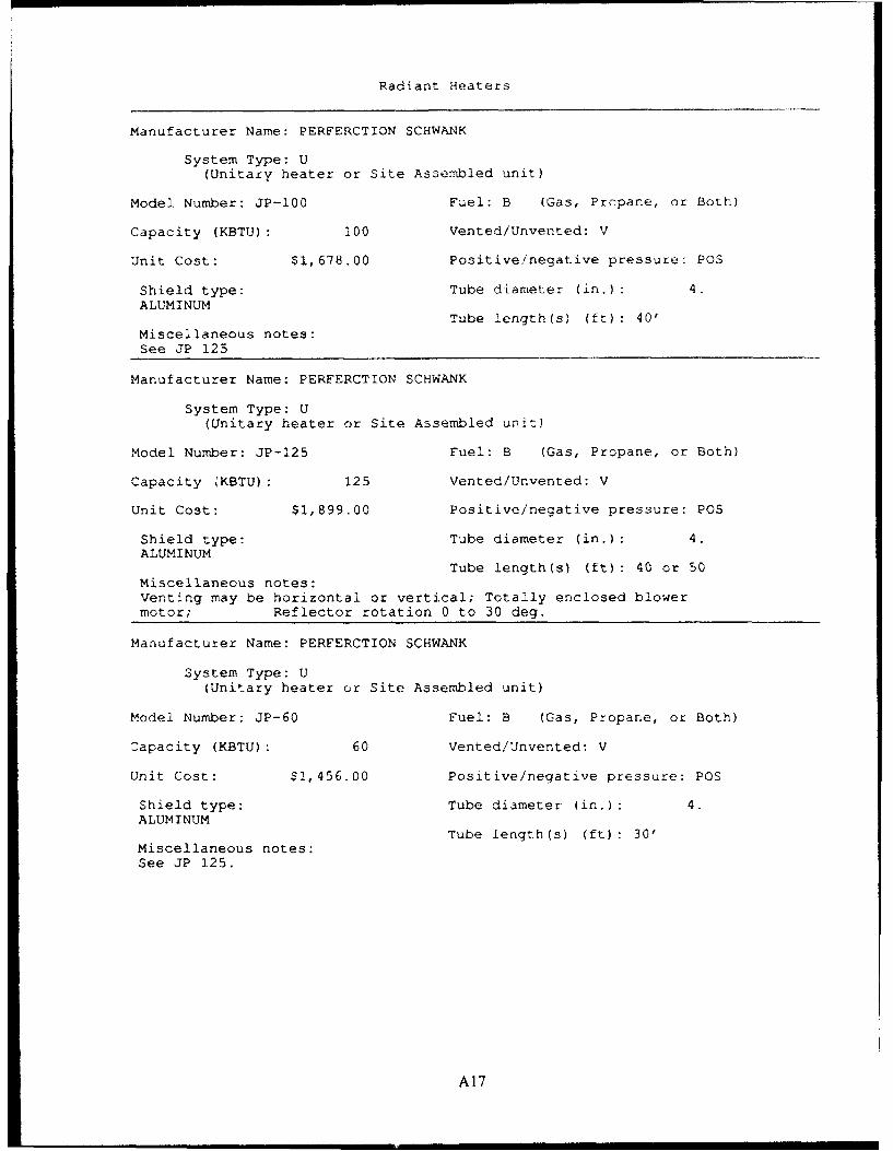
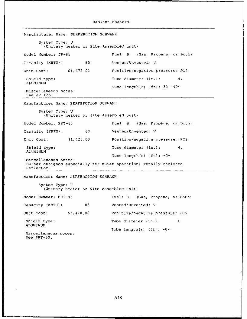
Perfection Schwanck, Inc. Waynesboro, GA Perfectiun SchwanrLk
Roberts-Gordon Buffalo, NY Co-Ray-Vac, Vantage 11.Gordon-Ray
Solaronics Rochester, MI Sur, t'ube
Sterling Gas-Fired Heating Equipment Westfield, MA tntra-PAk
Sun Technology Corporation Shelby TWP. MI Ray-Fee
12 Thomas Register of American Manufacturers (Thomas Publishing Co.. New York. NY, 1991); the "HPAC Info-dex" is ayearly index published in Heating, Piping, Air Conditioning (Cleveland, OH).
20
These relatively few manulacturers of gas-fired tube-type infrared radiant heaters produce tw..superficially similar products. While the details of the design and implementation of the variousappliances vary widely, infrared heating systems can be classified as either positive- or negative-pressuresystems, as determined by type of eductor used, either a blower assembly or a vacuum pump,respectively. Positive-pressure systems "blow" the products of combustion through the radiant tubeswhereas negative-pressure systems "pull" the combustion products through the heat exchanger tubes.Both types of systems include vented and unvented applications. Generally, unvented applications aremore likely to be positive-pressure systems. A single vacuum pump or blower may he siod to carry thecombustion products through the entire network of radiant tubes, or multiple units may he used (as whenseveral factory-assembled units are connected to a common exhaust). An advanitage of negative-pressuresystems is that since they maintain the radiant tube at less than atmnospheric pressures, they are lesslikely to leak if the tube is damaged. Positive-pressure units have the advantage that they handle onlycombustion air, and not the products of combustion.
Another way to classify radiant heating systems is as condensing or noncondensing. Systems withsufficient tube runs to allow the combustion gases to cool to a point where water begins to condense inthe combustion products make relatively efficient use of their fuel. Since this condition is predominantlydependent upon the length of the tube run, the question of a condensing or noncondensing system islargely implementation specific. That is, a radiant heating contractor installing a field assembled systemmay achieve a condensing system at one site, but not at another even though the same manufacturer'sequipment is installed on both jobs. Factory assembled units, which tend to be relatively smaller thanfield-assembled units, are generally noncondensing.
Other differences in commercial units include the thickness of the radiant tube, shielding options,fuel options, and burner configurations. Typically, radiant tubes are steel. (One manufacturer offers acast iron radiant tube designed to be more durable than the steel tubes, at a higher cost.) Differentmanufacturers offer different styles, shapes, and materials for the shielding placed over the radianttubing. Some provide end caps for the shields, while others leave them open. Some manufacturers uscside deflectors to keep radiant energy from hitting the walls, while others will instruct the installer to tiltthe shield. Typical fuel options are propane and natural gas. Most units use one burner per radianttube, while some are built with multiple, in-line burners. Units with multiple burners offer a more uni-form tube temperature throughout the system than single-bunter units.
Note that the many types of radiant units are simply variations on a common theme. Even so,these variations can tremendously impact the quality and efficiency of the final product. Nearly all themanufacturers' equipment will have most or all of the following components: (I) some type of eductoreither a vacuum pump or blower assembly; (2) a tubular heat exchanger surface (radiant tube); (3) aburner assembly; (4) an air supply system; (5) a reflector assembly; (6) suspension brackets; (7) gaspiping/connectors; and (8) a control apparatus.
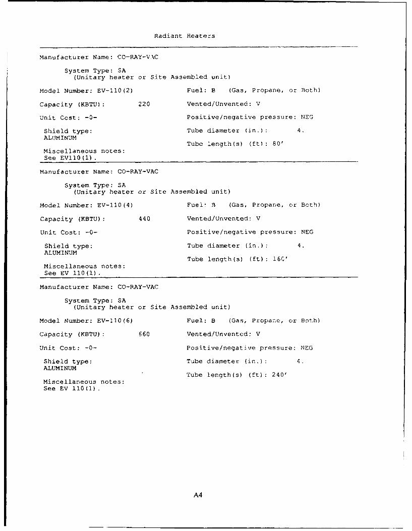
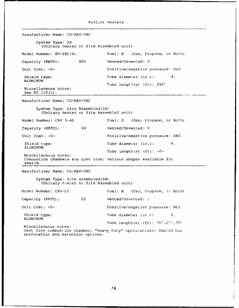
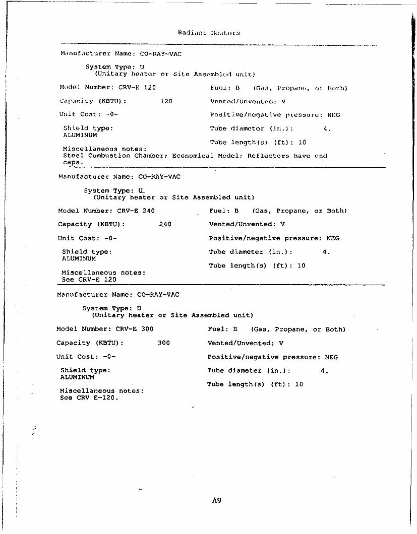
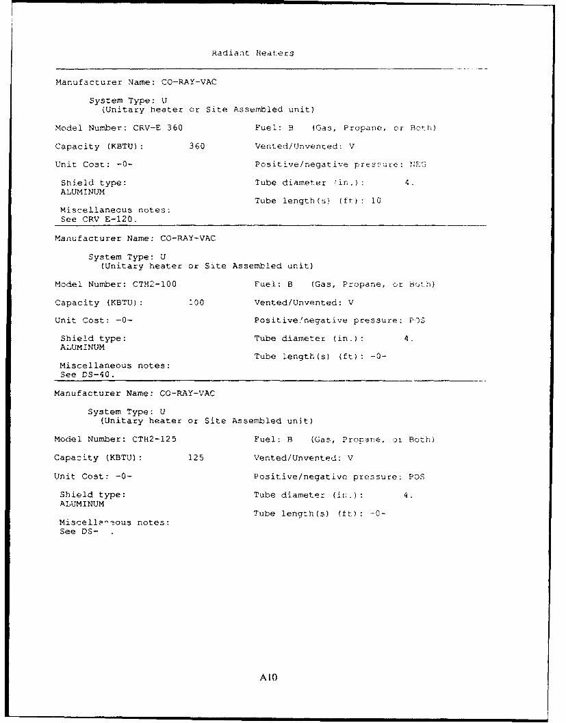
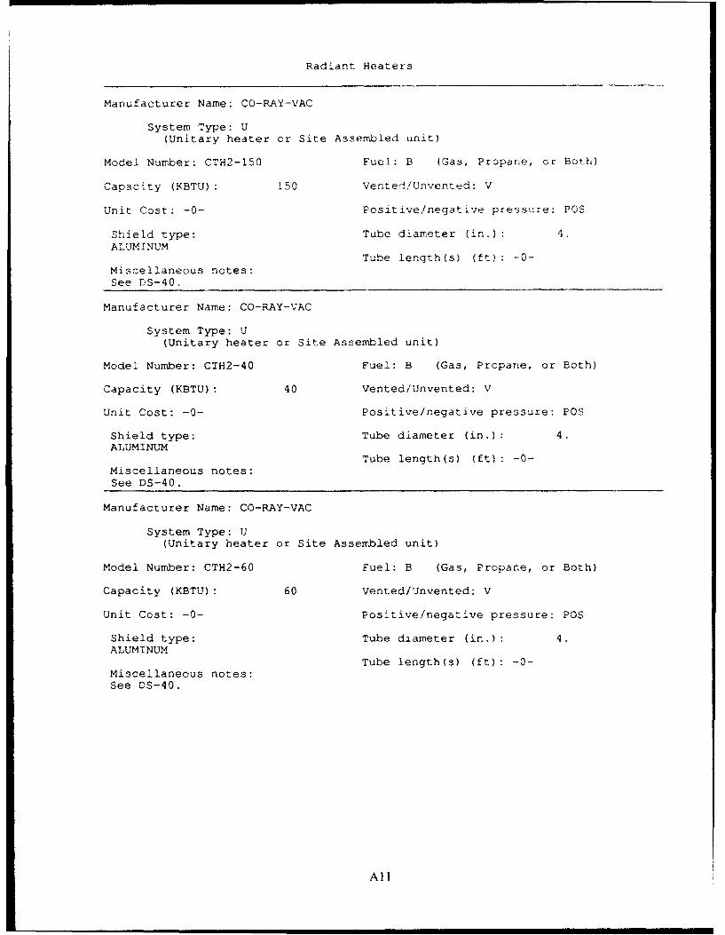
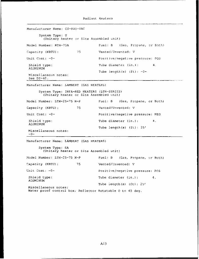
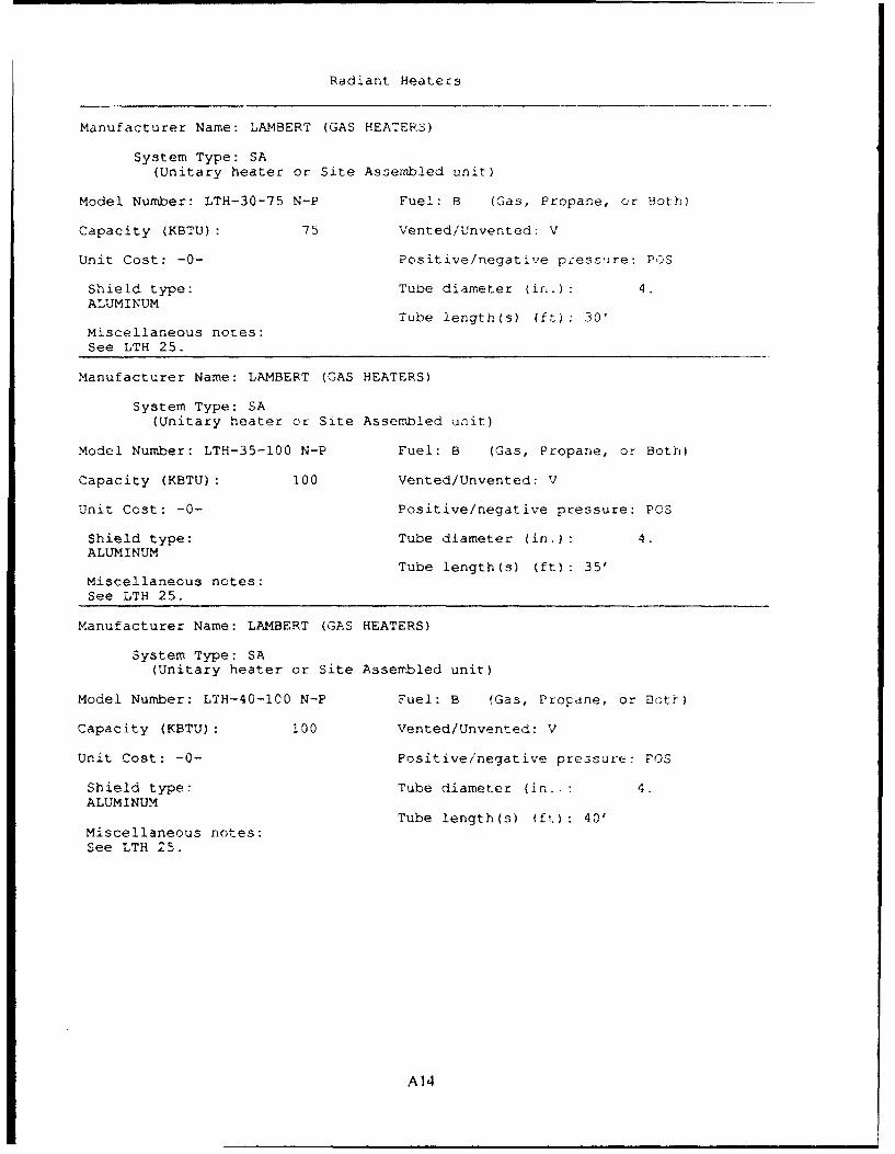
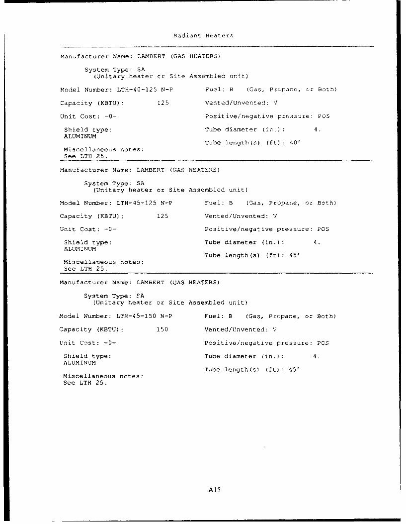
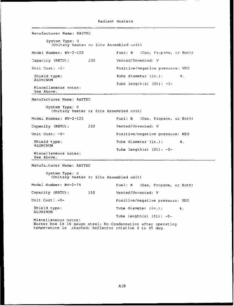
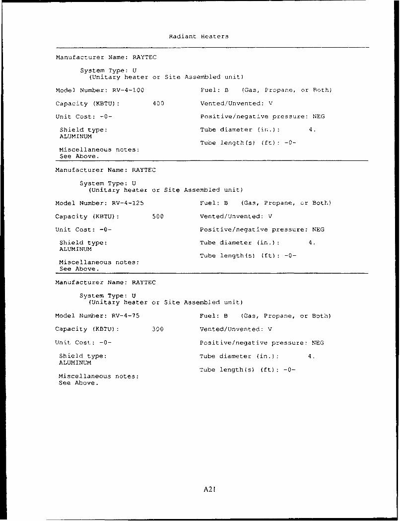
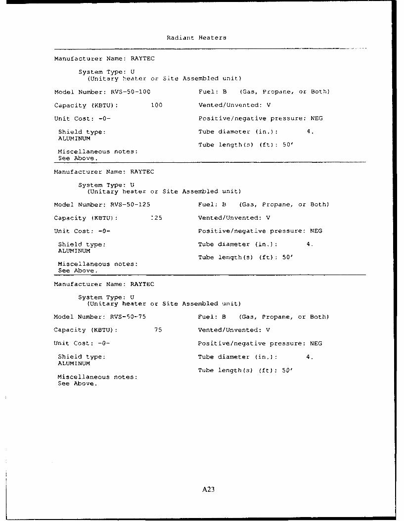
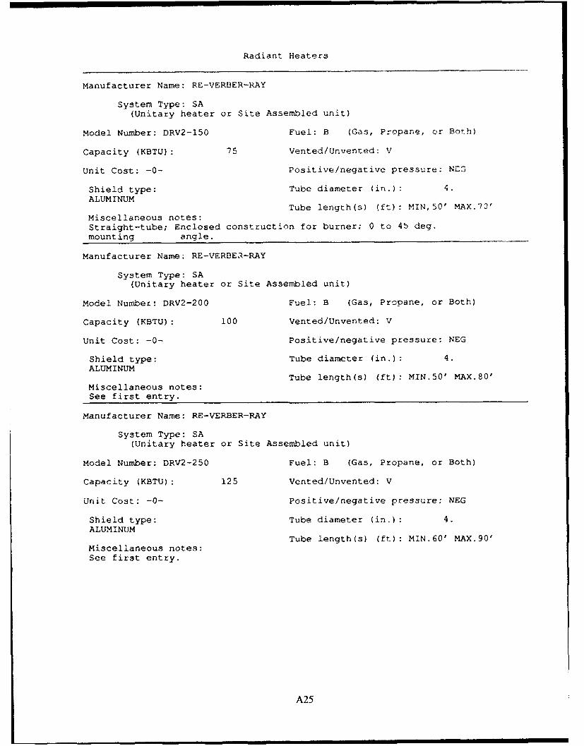
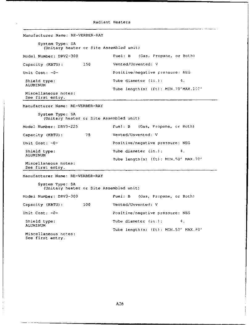
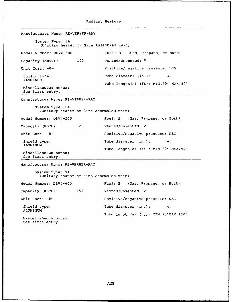
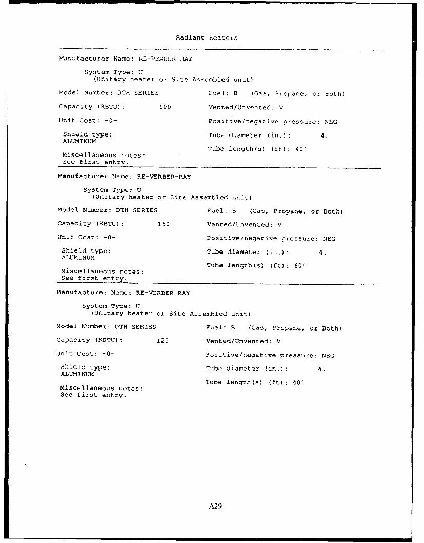
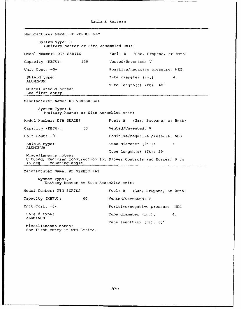
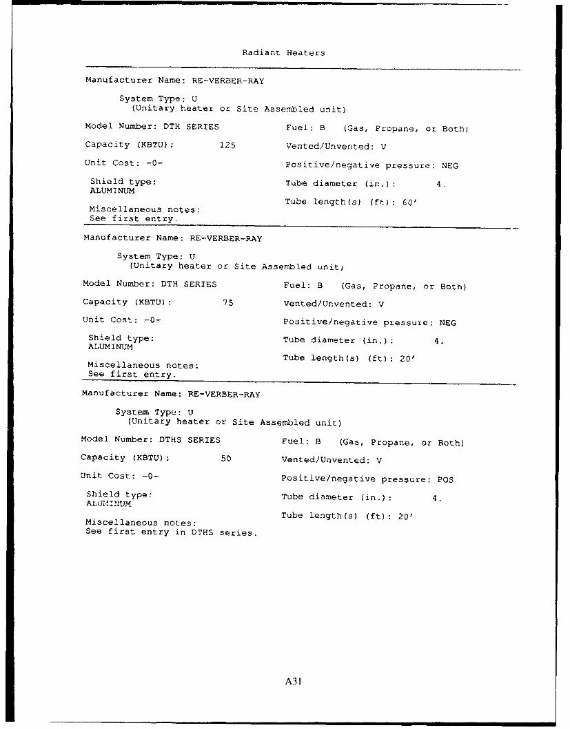
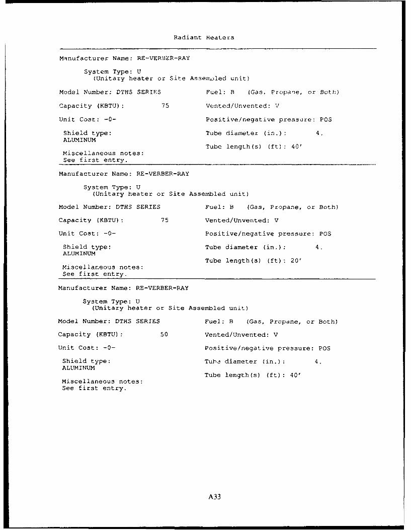
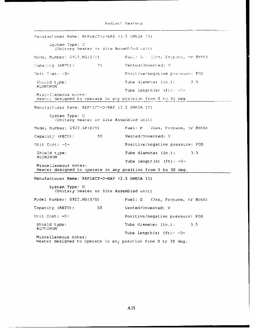
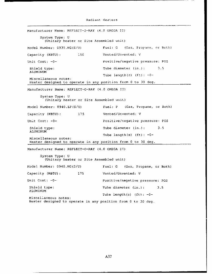
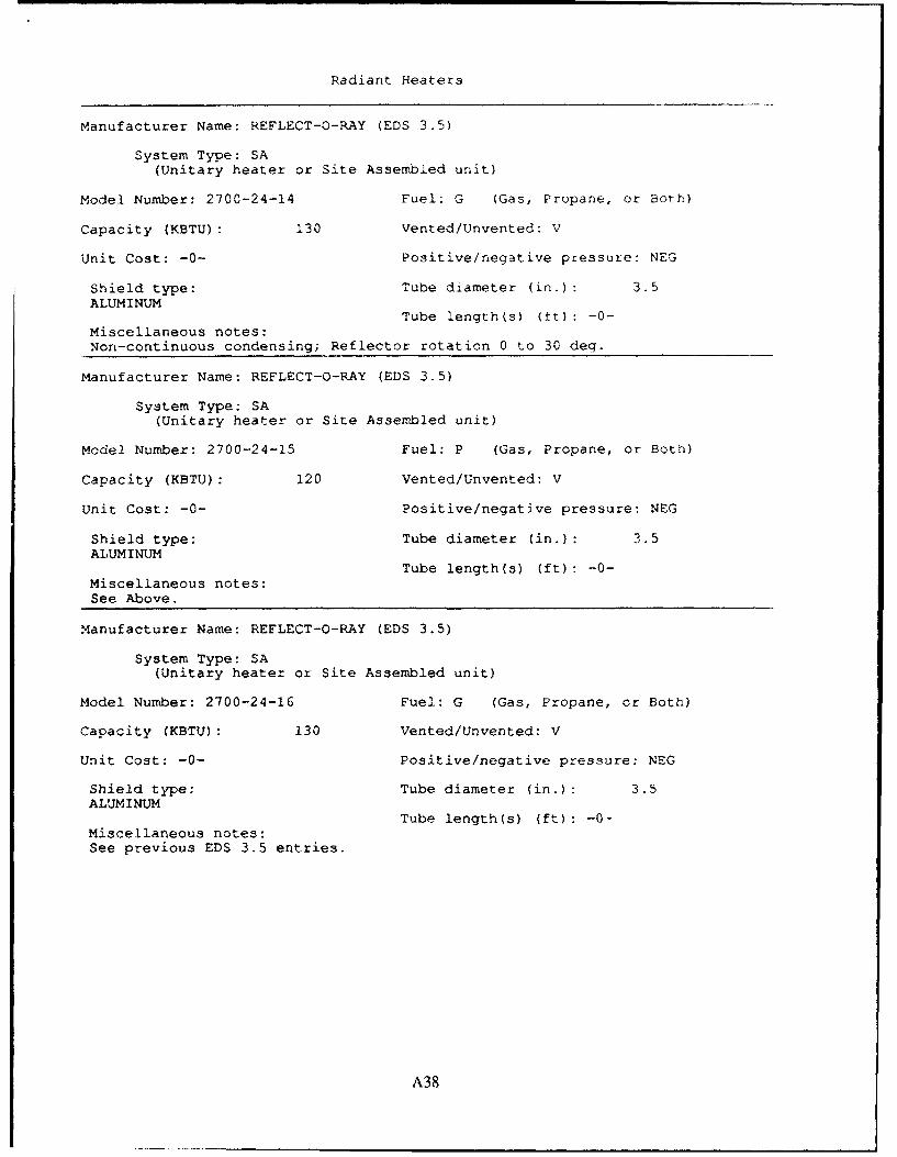
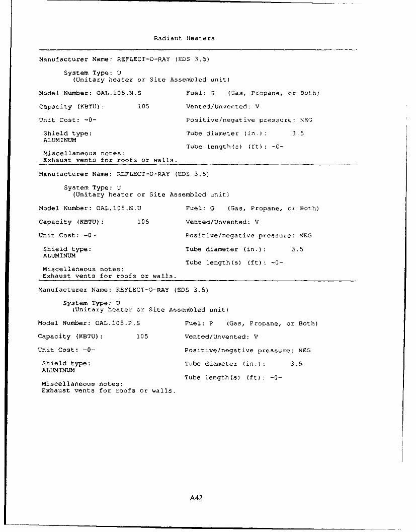
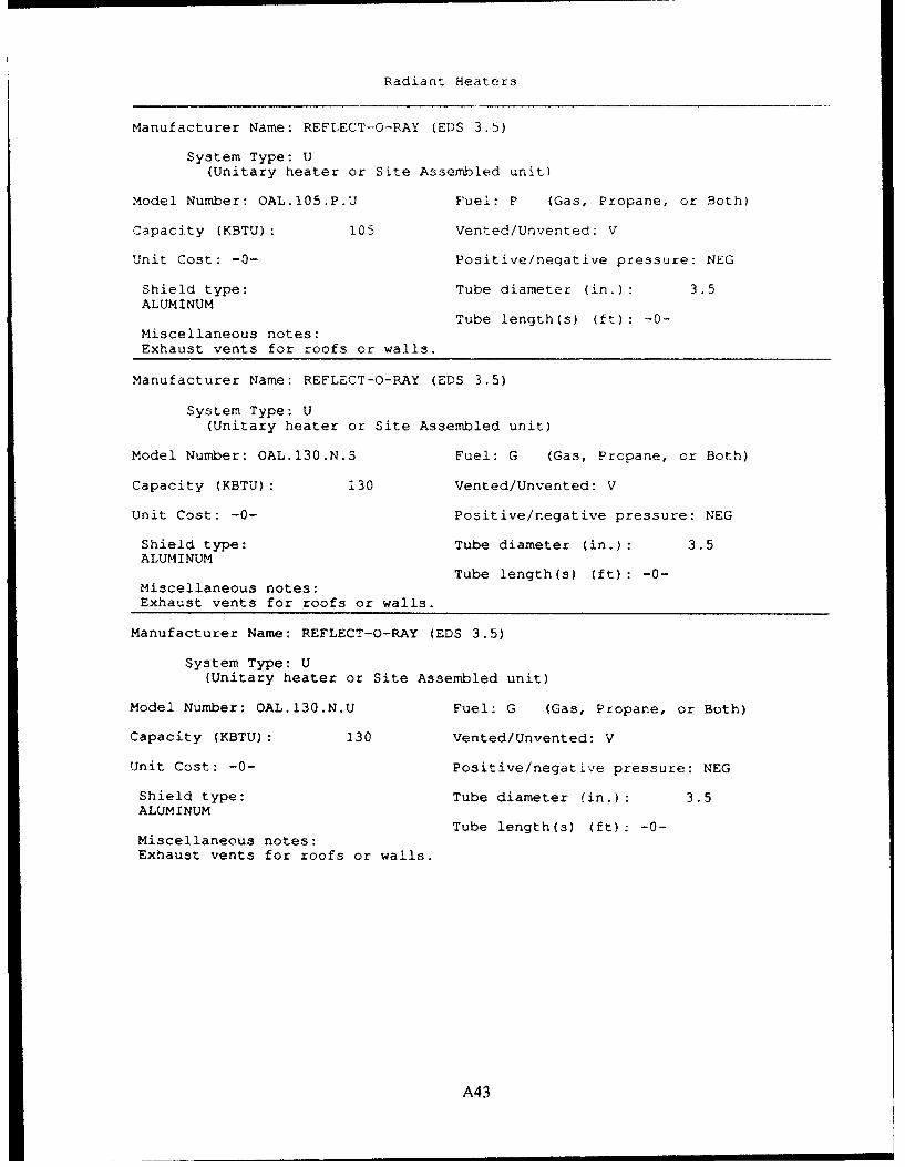
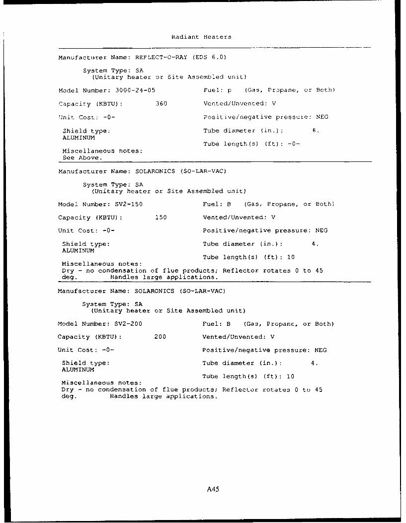
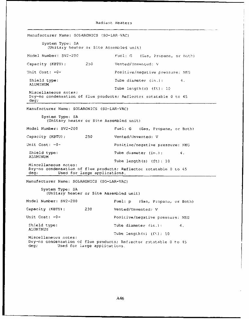
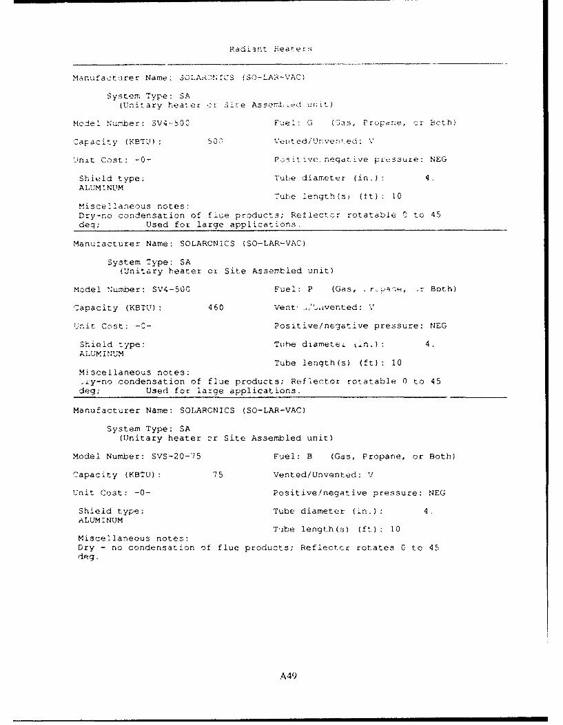
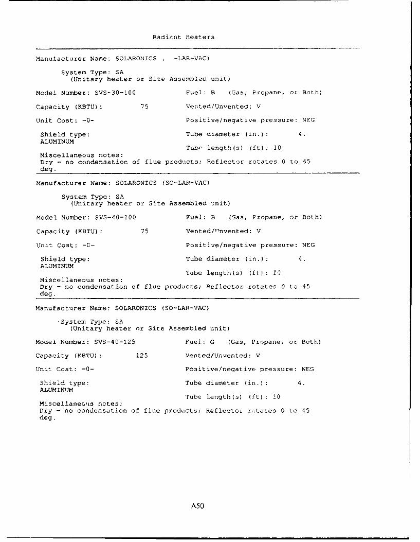
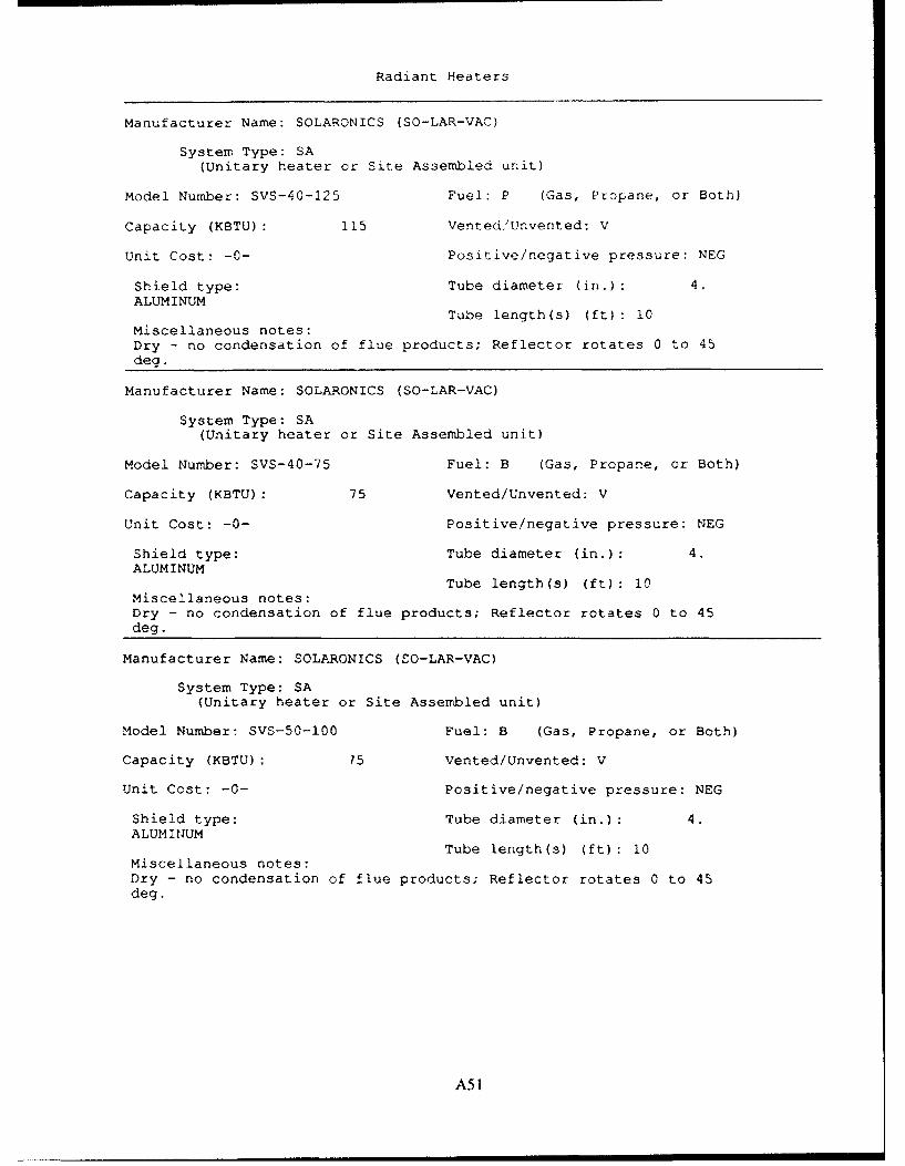
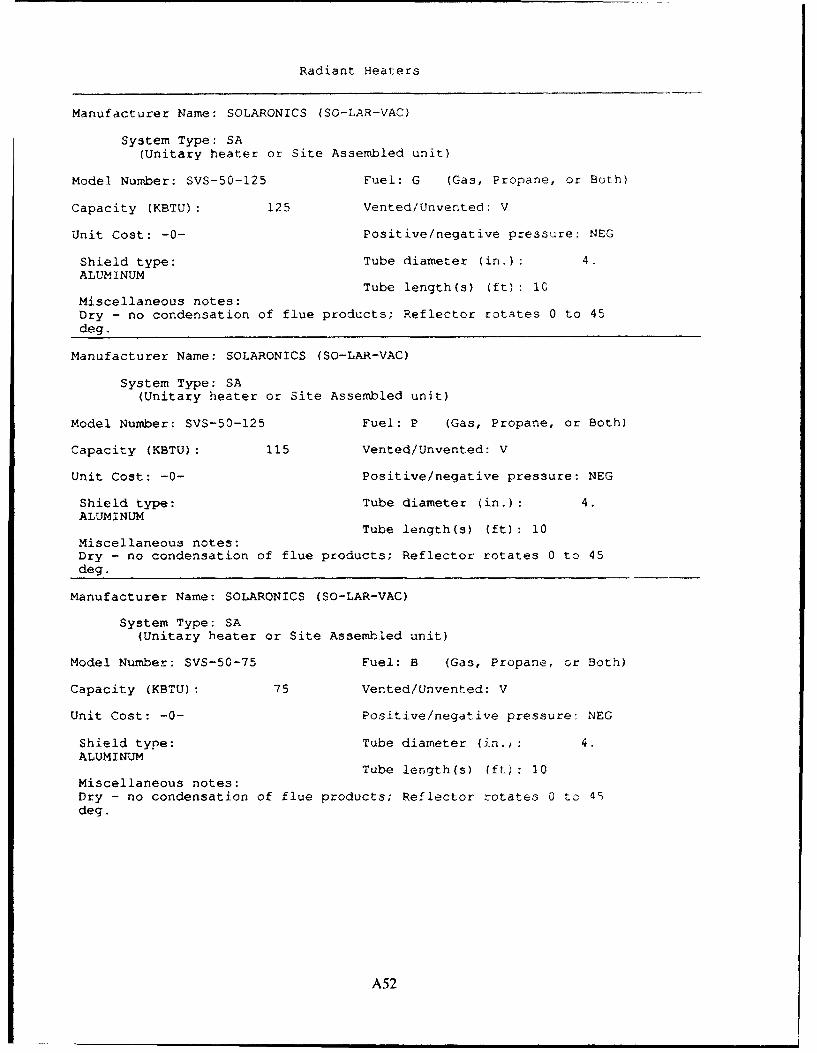
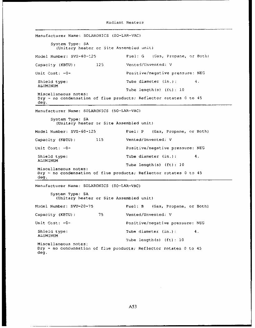
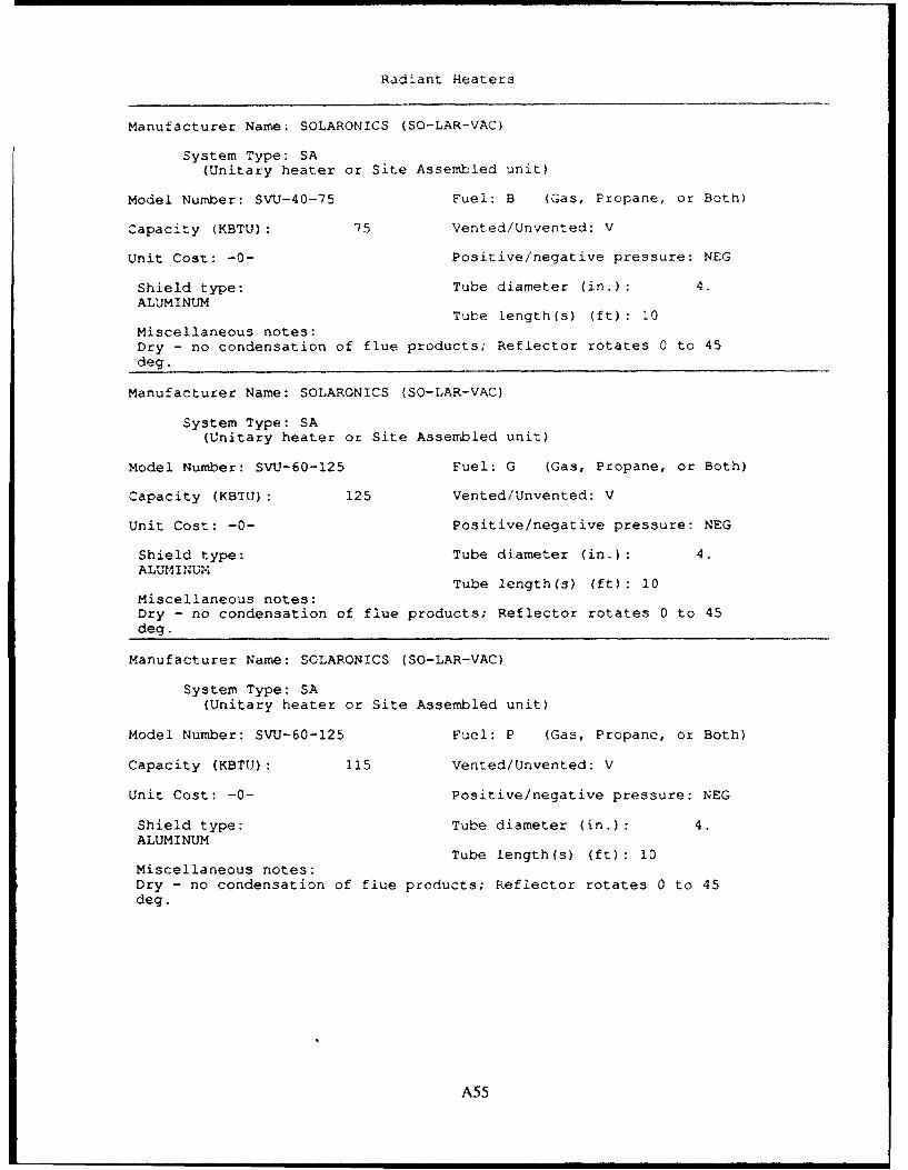
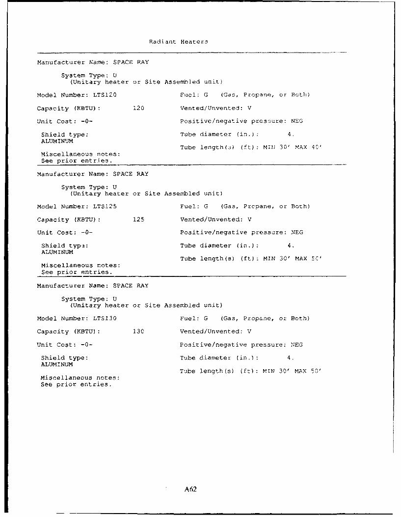
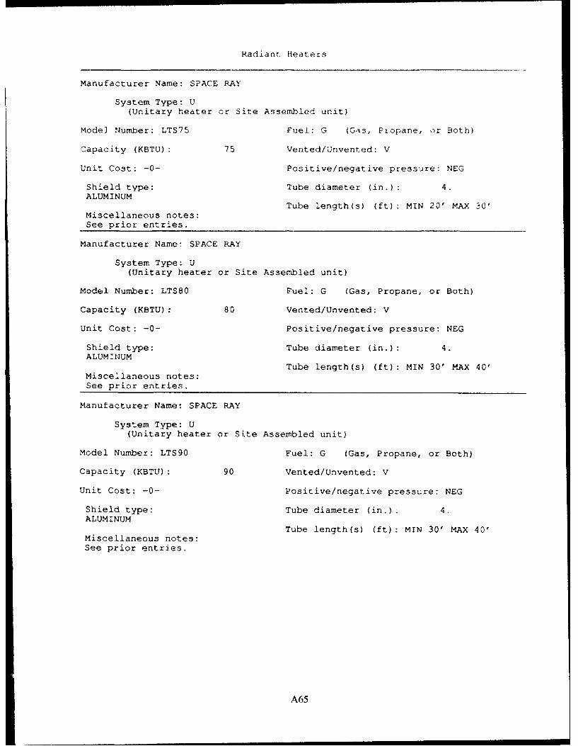
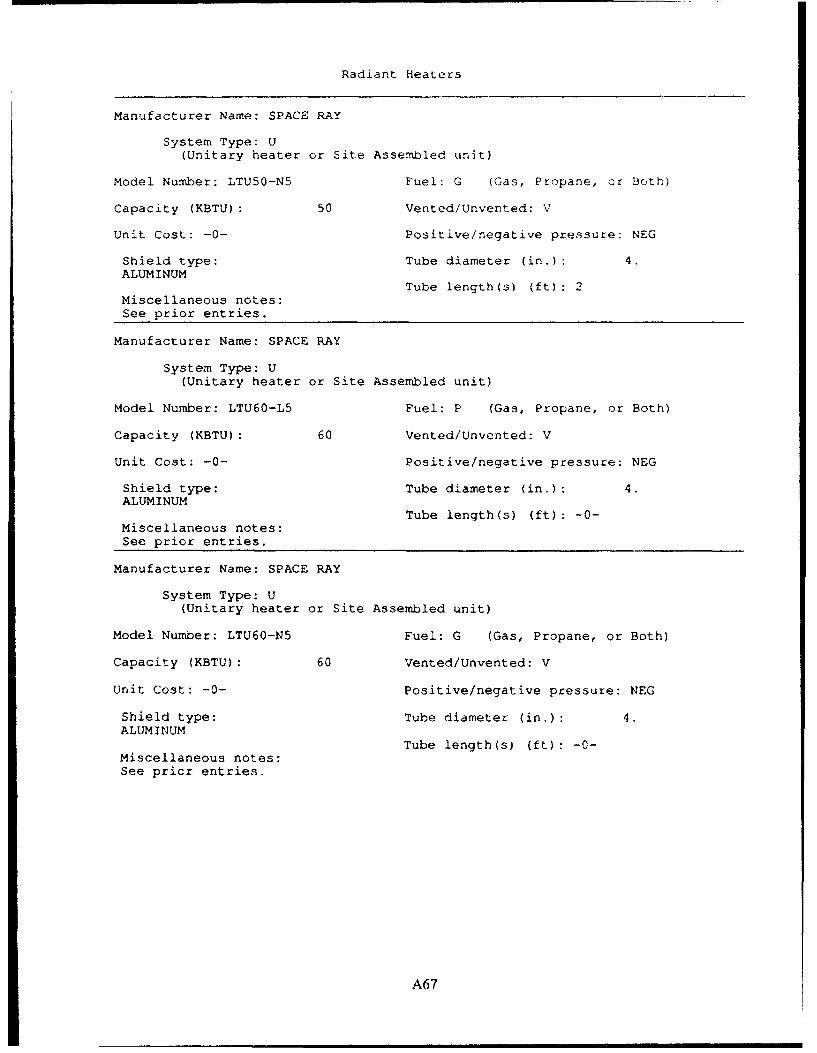
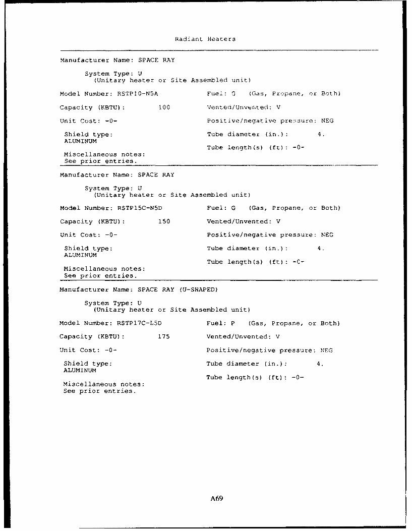
These basic components are assembled into marketable, competitive infrared heating systems.Manufacturers vary the size, structure, and combination of these components to differentiate theirproducts from those of their competitors. Ap,-zndix A provides a list of the systems produced by themanufacturers referenced in Table 1.
21
4 DEMONSTRATION AT FORT RILEY, KANSAS
Experimental Setup
A demonstration project for gas-fired, infrared radiant tube heaters wais undertaken beginning in1988 at Fort Riley, KS. Two buildings were selected for a side by side comparison of inflrared healersversus hydronic unit convection heaters. Both buildings chosen werc vehiclC maintcnance shops. Thefirst building is the control building, heated with hydronic convection uni! heaters, sometimes referrcd toas the convection building. This building is Fort Riley building number M390 and has . gross area of24,755 sq ft (23(X) m2). The second building is the lest building, Fort Riley building number 8370,sometimes known as the radiant building. Building 8370 has a gross area of 26,876 sq fz (2496 m-).This particular building type was selected for the large amount of such space in use by the Army.According to the Red Book. the Army has 76.2 million sq ft (7.1 million ni) of maintenani:c andproduction facilities in the continental United States, and 29.3 million sq, 11 (2.7 million m 2 ) outside thecontinental United States for a total of 105.5 million sq ft (98 million m•) of such facilities. Therefore.a successful demonstration for these facilities would have a large potential for application.
Both buildings are slab-on-grade construction with a vehicle maintenance area comprised ofservice bays, which are accessed by insulated metal overhead doors located on opposite sides of the.buildings. The side walls consist almost entirely of the bay doors separated by structural steel columnswith translucent panels over the doors to provide natural lighting. Both ends of the bay area arcconcrete block walls, one being an exterior wall and the other separating the maintenance bays f ro•nconditioned office space. This study is concerned only with the maintenance bay portions of (hebuildings. Furthermore, only the six bays on the north end of huilding 8390 were studied. Thisbuilding has additional bays on its south end with conditioned space in between these bays and the studybays. The roofs of both buildings are insulated double metal. Table 2 shows the appropriate overallheat transfer coefficient (U) values for the various components of the building.
The two buildings chosen for the study are located in the Custer Hill area of Fort Riley. This areaof the Fort has rolling hills and little vegetation. The buildings are both in the center of large parkingareas with small outlying buildings. No outlying buildings shade or shield the study buildings (Figures4 and 5).
There are two major differences between the two buildings, the heating systems and their size.Building 8370 has eight maintenance bays comprising about 85(0 sq ft (790 m2) while the portion of
Table 2
U-Values of Building Components
Item U Btu/hrft2x°F (W/m2x×C
Walls 0.05 (0.28)
Roofs 0.07 (0.40)
Doors 0.10 (0.57)
13 Facilities Engineering and Housing Annual Summary of Operations (Offiwe of the Assistant Chief of Engineers IOACEI,
1988), pp 2, 5. 50.
22
Fi gure 4. Building 8370, the Radiant Building.
Figtire 5. Iluiilding 8390, the C'onvection Buildinp.
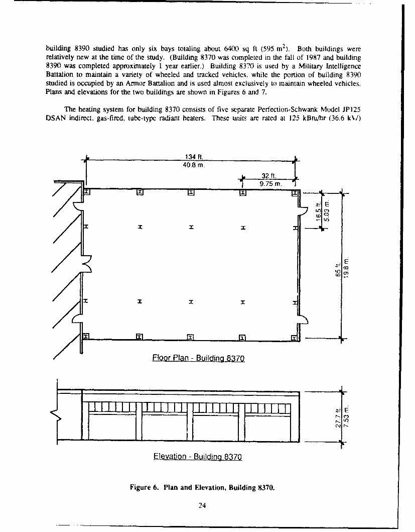
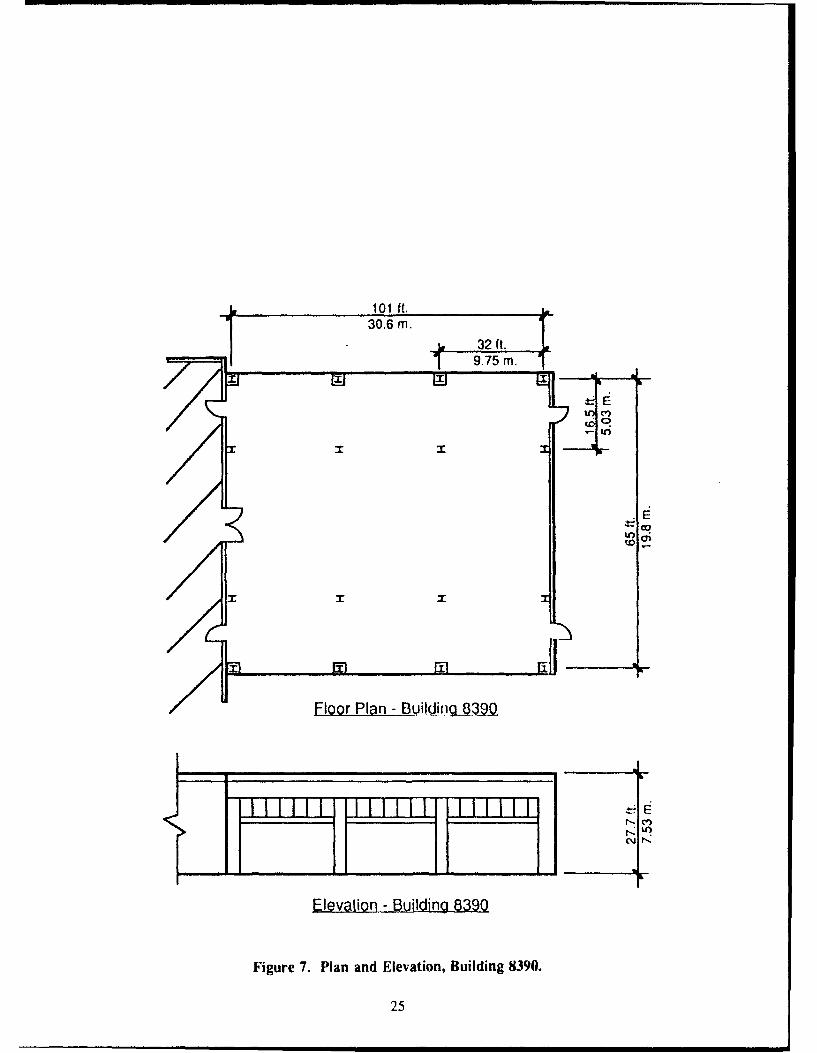
building 8390 studied has only six bays totaling about 6400 sq ft (595 mi2 ). Both buildings wererelatively new at the time of the study. (Building 8370 was completed in the fall of 1987 and building8390 was completed approximately 1 year earlier.) Building 8370 is used by a Military IntelligenceBattalion to maintain a variety of wheeled and tracked vehicles, while the portion of building 8390studied is occupied by an Armor Battalion and is used almost exclusively to maintain wheeled vehicles.Plans and elevations for the two buildings are shown in Figures 6 and 7.
The heating system for building 8370 consists of five separate Perfection-Schwank Model JP125DSAN indirect, gas-fired, tube-type radiant heaters. These units are rated at 125 kBtu/hr (36.6 k%1)
13411. ft40.8 m.
be 32 ft. LS9.75
Floor Plan - Building 8370
cm
r LO
Elevation - Building 8370
Figure 6. Plan and Elevation, Building 8370.
24
101 ft.30.6 m.
, 0 ... ,32 ft..•1 9.75 M..
E
Floor Plan - QBvkdiing-a9-Q
M IL 11" 1 -11 1
Ir- T 2
fL
Elevation - Building 8390
Figure 7. Plan and Elevation, Building 8390.
25
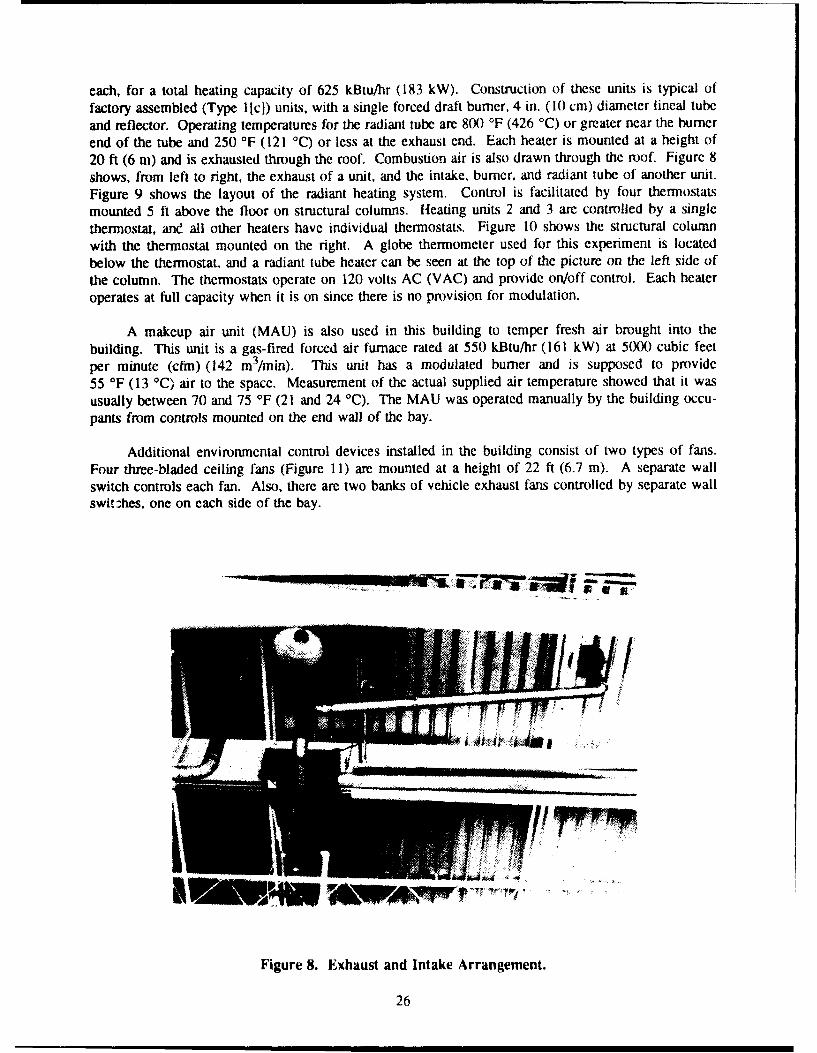
each, for a total heating capacity of 625 kBtu/hr (183 kW). Construction of these units is typical of
factory assembled (Type l[c]) units, with a single forced draft burner, 4 in. (10 cm) diameter lineal tube
and reflector. Operating temperatures for the radiant tube are 800 OF (426 °C) or greater near the burner
end of the tube and 250 OF (121 0C) or less at the exhaust end. Each heater is mounted at a height of20 ft (6 m) and is exhausted through the roof. Combustion air is also drawn through the roof. Figure 8
shows, from left to right, the exhaust of a unit, and the intake, burner, and radiant tube of another unit.
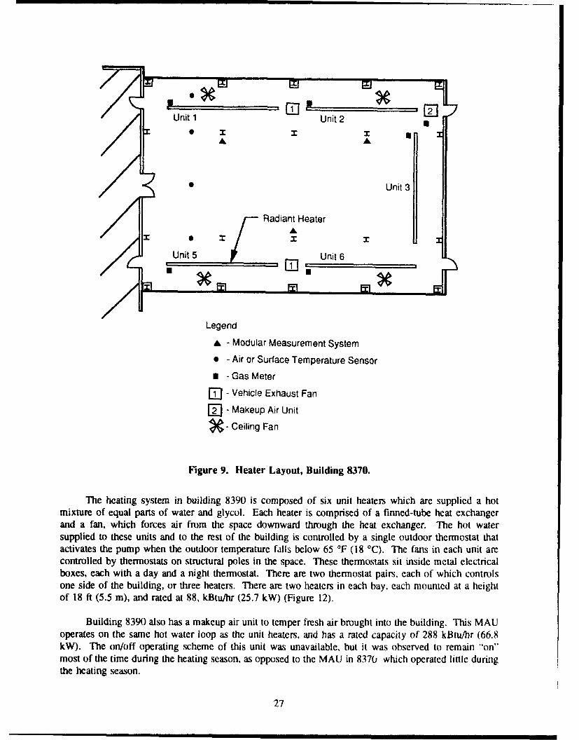
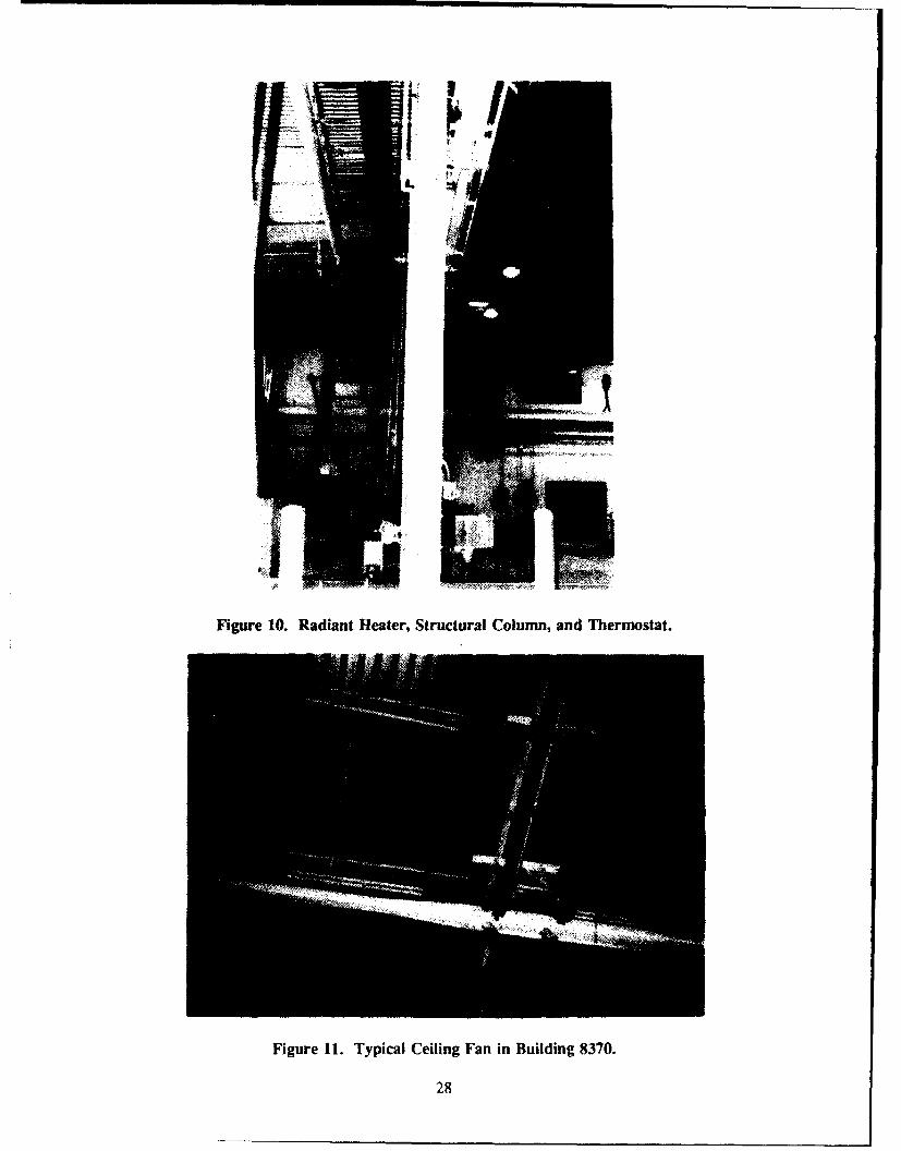
Figure 9 shows the layout of the radiant heating system. Control is facilitated by four thermostatsmounted 5 ft above the floor on structural columns. Heating units 2 and 3 are controlled by a singlethermostat, ane all other heaters have individual thermostats. Figure 10 shows the structural columnwith the thermostat mounted on the right. A globe thermometer used for this experiment is locatedbelow the thermostat. and a radiant tube heater can be seen at the top of the picture on the left side ofthe column. The thermostats operate on 120 volts AC (VAC) and provide on/off control. Each heateroperates at full capacity when it is on since there is no provision for modulation.
A makeup air unit (MAU) is also used in this building to temper fresh air brought into thebuilding. This unit is a gas-fired forced air furnace rated at 550 kBtu/hr (161 kW) at 5000 cubic feetper minute (cfm) (142 m3/min). This unit has a modulated burner and is supposed to provide55 OF (13 0C) air to the space. Measurement of the actual supplied air temperature showed that it wasusually between 70 and 75 OF (21 and 24 °C). The MAU was operated manually by the building occu-pants from controls mounted on the end wall of the bay.
Additional environmental control devices installed in the building consist of two types of fans.Four three-bladed ceiling fans (Figure 11) are mounted at a height of 22 ft (6.7 m). A separate wallswitch controls each fan. Also, there are two banks of vehicle exhaust fans controlled by separate wallswit:hes, one on each side of the bay.
Figure 8. Exhaust and Intake Arrangement.
26
"Unit 3
pf Radiant Heater
*Unit 5 Unit 6
Legend
A - Modular Measurement System
* - Air or Surface Temperature Sensor
n - Gas Meter
E' - Vehicle Exhaust Fan
M2 - Makeup Air Unit
I- Ceiling Fan
Figure 9. Heater Layout, Building 8370.
The heating system in building 8390 is composed of six unit heaters which are supplied a hotmixture of equal parts of water and glycol. Each heater is comprised of a finned-tube heat exchangerand a fan, which forces air from the space downward through the heat exchanger. The hot watersupplied to these units and to the rest of the building is controlled by a single outdoor thermostat thatactivates the pump when the outdoor temperature falls below 65 'F (18 °C). The fans in each unit arecontrolled by thermostats on structural poles in the space. These thermostats sit inside metal electricalboxes, each with a day and a night thermostat. There are two thermostat pairs, each of which controlsone side of the building, or three heaters. There are two heaters in each bay, each mounted at a heightof 18 ft (5.5 m), and rated at 88, kBtu/hr (25.7 kW) (Figure 12).
Building 8390 also has a makeup air unit to temper fresh air brought into the building. This MAUoperates on the same hot water loop as the unit heaters, and has a rated capacity of 288 kBtu/hr (66.8kW). The on/off operating scheme of this unit was unavailable, but it was observed to remain "on"most of the time during the heating season, as opposed to the MAU in 8370 which operated little duringthe heating season.
27
Figure 10. Radiant Heater, Structural Column, and Thermostat.
Figure 11. Typical Ceiling Fan in Building 8370.
28
There are also vehicle exhaust fans installed in building 8390, similar to those in 8370. Four airrecirculation devices to reduce thermal stratification arc also employed. Each of these devices is acentrifugal fan mounted near the ceiling with an 8-in. (20-cm) duct that hangs down to about 2 It(0.6 m) above the floor. Each of these units is controlled by a separate wall switch.
The data collected for this demonstration fall into two time categories, data taken every 3 minutesand data taken every hour. The data taken every 3 minutes can he further subdivided into three cate-gories: (1) thermal comfort data, (2) building dynamics data, and (3) heater controls data. Datacollected to ascertain thermal comlort include globe thermometer temperature, air velocity, ambient ternperature, and dew point temperature. Data collected to track building dynamics include ceiling andvehicle exhaust fan status, and door status. Heater controls data consist of heater status and temperatureat the thermostat.
The data taken every hour have two subcategories, averages and totals. The averages categoryincludes air stratification temperatures taken at eight elevations, component directions of the globe
Unit HeatersS r
S' ,
:0a El T] z'
Legend
& - Modular Measurement System
* - Air or Surface Temperature Sensor
v - Gas Meter
0 - Water Tcmperature Sensor
1 - Vehicle Exhaust Fan
S- Makeup Air Unit
E - Recirculation Fan
Figure 12. Heater Layout, Building 8390.
29
thermometers (six components per globe), and ceiling temperature. The only total item kept % as energyconsumption, either gas consumption for the radiant building or hot water flow and tcmperaturedifferences for the convection building,
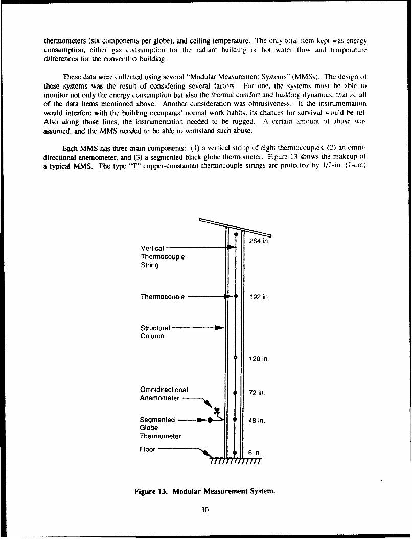
These data were collected using several "Modular Measurement Systems" (MMSs). The design ofthese systems was the result of considering several factors. For one, the systems must be able tomonitor not only the energy consumption but also the thermal comfort and building dynamics, that is, allof the data items mentioned above. Another consideration was obtrusiveness: If the instrumentationwould interfere with the building occupants' normal work habits, its chances for survival would be nil.Also along those lines, the instrumentation needed to be rugged. A certain amount of abuse wasassumed, and the MMS needed to be able to withstand such abuse.
Each MMS has three main components: (I) a vertical string of eight thermocouplcs. (2) an omm-directional anemometer, and (3) a segmented black globe thermometer. Figure 13 shows the makeup ofa typical MMS. The type "T" copper-constantan thermocouple strings are pro(ected by 1/2-in. (I-cm)
264 in.VerticalThermocoupleString
Thermocouple 0 192 in.
StructuralColumn
120 in.
Omnidirectional 72 in.Anemometer
Segmented -~ 1W48 in.GlobeThermometer
Floor 0 6 in.
Figure 13. Modular Measurement System.
30
metal conduit with the dissimilar mietal junctions exposed to the air. The oninidirectional anemometerand segmented globe thermometer are mounted inside a protective cage constructed of' l/2-in. (I-cm)hail screen. Each globe thermometer is a 6-in. (15-cm) copper sphere painted matte black, with sixsegments arranged according to the six cartesian directions. A thermocouple wa~s attached to eachsegment and the globes were filled with fiberglass insulation to preclude radiant heal exchange betweensegments. Unpublished research by Jones and Tao indicates that the average of the six measurementsfrom each segment is essentially the same as the measurement of an unsegmerited globe thermome-ter.' 4 Segmented globes were used in this case to enable measurement of radiant asymmetry, Theglobe thermometer/anemometer pairs are mounted at a height of about 48 in. t 122 cm), with the tip ofthe anemometer positioned approximately 6 in. (15 cm) above the globe thermometer. Figure 14 showsa globe thermometer in a Modular Measurement System.
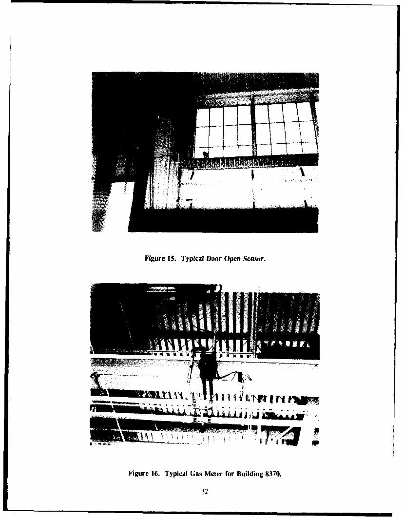
Monitoring of on-off status of ceiling fans and exhaust fans was accomplished using relay circuitsthat closed when the fans were in use. Bay door status was monitored by using infrared beam sensorsof the type used with automatic garage door openers, to reverse direction when the infrared beam isbroken, and a custom circuit was used to translate the square wave signal to an on-off type of signal.These sensors were placed such that the door must be opened 12 in. (30 cm) or more to break the beam.Figure 15 shows one of these sensors.
Energy usage in building 8370 was monitored by measuring natural gas flow into each radiantheater and the makeup air unit using commercial gas meters (Figure 16). The gas meters were equippedwith pulse counters that sent a pulse to the data logger for each cubic foot (.028 m3) of gas con.,,umed.The data logger then recorded a cumulative total for each hour. Energy consumption was calculated
Figure 14. Globe Thermometer/Anemometer Set.
14 Cited in William F. Niedringhaus. A Field Conipartson of Radiant and Convective Ieating Sy'vstems in Arn) Maintenance
Facilities, a Master's ihesis (DLepartment o( MechaniLal Engineering. Kansas State Univrsity. Manhattan, KS. 1988). p 19.
31
Figure 15. Typical Door Open Sensor.
Figure 16. Typical Gas Meter for Building 8370.
32
based on the conversion of 9 kBtu (1055.04 W's) per cubic foot (0.028 m3). Each radiant heater andthe MAU were also monitored for on-time, using relays.
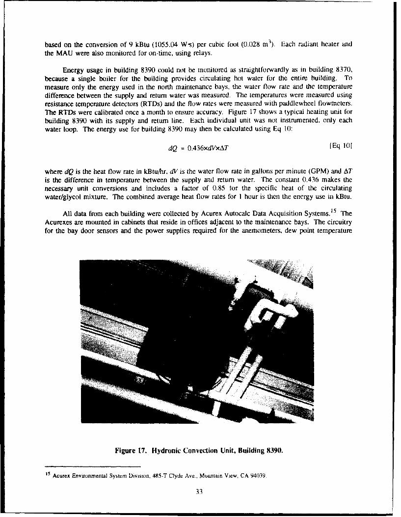
Energy usage in building 8390 could not be monitored as straightforwardly as in building 8370,because a single boiler for the building provides circulating hot water for the entire building. Tomeasure only the energy used in the north maintenance bays, the water flow rate and the temperaturedifference between the supply and return water was measured. The temperatures were measured usingresistance temperature detectors (RTDs) and the flow rates were measured with paddlewheel flowmeters.The RTDs were calibrated once a month to ensure accuracy. Figure 17 shows a typical heating unit forbuilding 8390 with its supply and return line. Each individual unit was not instrumented, only eachwater loop. The energy use for building 8390 may then be calculated using Eq 10:
dQ = 0.436xdVxAT [Eq 101
where dQ is the heat flow rate in kBtu/hr, dV is the water flow rate in gallons per minute (GPM) and ATis the difference in temperature between the supply and return water. The constant 0.436 makes thenecessary unit conversions and includes a factor of 0.85 for the specific heat of the circulatingwater/glycol mixture. The combined average heat flow rates for I hour is then the energy use in kBtu.
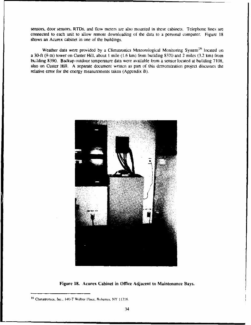
All data from each building were collected by Acurex Autocalc Data Acquisition Systems.15 TheAcurexes are mounted in cabinets that reside in offices adjacent to the maintenance bays. The circuitryfor the bay door sensors and the power supplies required for the anemometers, dew point temperature
~W,
Figure 17. Hydronic Convection Unit, Building 8390.
1 Acurex Environmental System Division, 485-T Clyde Ave., Mountain View, CA 94039.
33
sensors, door sensors, RTDs, and flow meters are also mounted in these cabinets, Telephone lines areconnected to each unit to allow remote downloading of the data to a personal computer. Figure 18shows an Acurex cabinet in one of the buildings.
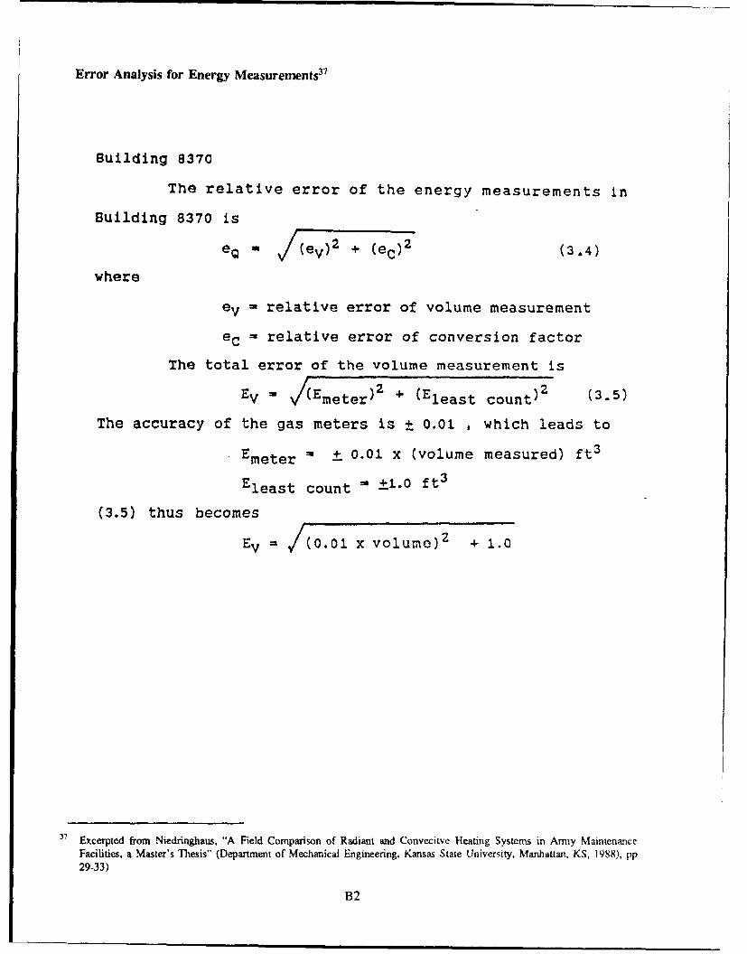
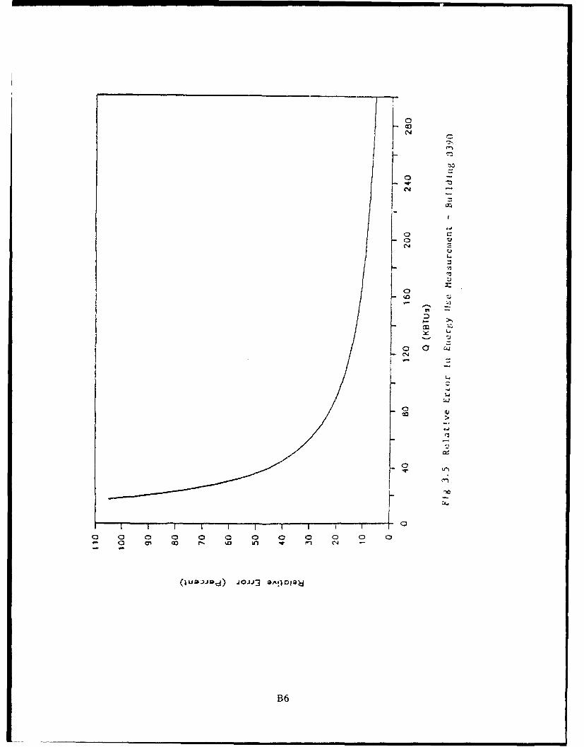
Weather data were provided by a Climatronics Meteorological Monitoring System16 located ona 30-ft (9-m) tower on Custer Hill, about 1 mile (1.6 kin) from building 8370 and 2 miles (3.2 km) frombL.ding 8390. Backup outdoor temperature data were available from a sensor located at building 7108,also on Custer Hill. A separate document written as part of this demonstration project discusses therelative error for the energy measurements taken (Appendix B).
Figure 18. Acurex Cabinet in Office Adjacent to Maintenance Bays.
16 Climatronics. Inc., 140-T Wilbur Place, BohemLa, NY 11716.
34
The data collected were analyzed to compare the perfrmance of the two building heating systemswith respect to three major concerns: (1) energy consumption, (2) thermal comfort, and (3) stratification.These three aspects of heating are indicators of the attainment or nonattainment ol the hulk of the radiantheater manufacturers' claims. First, however, a methodology for making valid comparisons needed to bedeveloped.
Energy Consumption
To compare the two heating systems studied, the differences in the physical characteristics of thetwo buildings and the character of the data collected needed to be considered. In terms of floor area.building 8370 is 33 percent larger than the studied portion of building 8390. To approxinmate a compar-ison of two equally sized buildings, the energy use data from building 8390 were scaled by a factor of'1.33. Second, energy use was monitored in twu different ways between me two buildings. In building8370 gas usage (fuel input) was metered. However, in building 8390, energy input to the hydronic unitswas measured, since they received hot water from a boiler in common with the rest of the building.Therefore, the energy figures for building 8390 need to be adjusted to account for the efficiency of theboiler.
Boiler efficiency is expressed in two ways, in combustion efficiency and in overall efficiency.Combustion efficiency is calculated by subtracting the stack loss from the fuel input and then dividingthis quantity by the fuel input. According to ASHRAE, combustion efficiency tor a noncondensingboiler ranges from 75 to 86 percent. 17 For this analysis, a rather optimistic combustion efficiency of85 percent was assumed for the building 8390 boiler. Overall efficiency is defined as simply the grossoutput divided by the input. Overall efficiency is always lower than combustion efficiency, due to heatlosses through the walls of the boiler (usually called radiation loss). For this study, a radiation loss of10 percent was assumed indicating that the overall efficiency for the building 8390 boiler would betaken to be 75 percent. The energy figures for building 8390 were adjusted accordingly, so that energyconsumption from both buildings could be compared in terms of fuel input.
Since it is difficult to make generalizations and conclusions from 3-minute snips in time, the datascans were processed into daily averages to make these comparisons. This conversion was done usingcomputer programs written for this project at USA CERL to transform the data files from the dataloggers into a format easily readable by spreadsheet software. The data were then uploaded into spread-sheets and further processed. Figure 19 shows the results of such processing.
Figure 19 represents the overall energy usage for the studied portions of both buildings inFebruary 1988. Figures 20 and 21 show similar compilations for March and April. There are noticeablepeaks in the energy use for 11 February, which is attributable to subzero outdoor temperatures on thatdate. It can be seen that building 8370 used substantially more energy than building 8390 from 1February through 24 February. After that period, the difference between the two buildings is lesspronounced, until the first 6 days of March when 8370 again used much more energy than did building8390. Disregarding the period from 23 March through 27 March. when the heaters in building 8370were turned off, the rest of March shows no clear difference in consumption between the taildings. Theconsumption plot for April shows a widely varying pattern, reflecting the wide variance in outside airtemperature during the month. Note that the hot water pump for building 8390 shut down on April 16,while the radiant heaters in building 8370 continued to operate through the end of the month.
As expected. energy consuription in the two buildings varied inversely with outside temperature.tliocver. the rate at which the energy use changes with outside temperature provides some insight intothe relative performance of the two buildings. Figures 22 and 23 show plots of cnergy usage versusoutside air temperature for 8370 and 8390. respectively. The plots show the daily energy usage andrcgression lines (calculated using only nonzero data) with confidence bands, which show large standarder'ror for l•ith buildings. The two regression bands are shown superimposed on Figure 24. N6te thatthe hands overlap for all but the lowest temperatures, where the indication is that building 8390 is moreenergy efficient at lower temperatures. The main reason for this difference and the steeper slope of thebuilding 8170 regression line is the surprisingly high energy consumption for building 8370 in February.
Table I show-, the monthly and grand totals for energy usage in both buildings. Over theFebruary through April 1988 period, building 837(0 used 43 percent more energy than did building 8390.This certainly was not the expected result, since the type of building being studied would appear to heideal for application of low-intensity infrared radiant heating.
There are a number of reasons why building 8370 showed unexpectedly high energy usage for theperiod in question. Most notably, the occupants of 8370 used the radiant heating system controls ason/off switches, rather than as thermostatic controls. That is, the occupants would set the thermostats ata high temperature to run continuously without ever cycling off. In addition, since there were no pro-visions for aulomatic setback, the thermostats apparently were left at these high temperatures even atnight. Figures 25 through 30 show that the temperature in building 9390) dropped sharply at night, whilethe temperature in building 8370 remained constant or increased during the same unoccupied time. Notethat the temperatures shown in the figures for 8390 have been reduced by 20 IF (I I 'C) to improve theclanty of the graph. The overheating problem in 8370 was not overcome until the fourth week ofFebruary when the supervisory personnel in the building becamtL more familiar wkithl the healing systenm
37
24
22
70
76
79
12
10
6
lo 1 30 so
OU Iý71E ARq IFEW~~ERi 1 ,rI (1;7
Figure 22. Relationship Between Outside Temperature and Energy Use for Building 8370.
22'
20
16
14 -
S12-
6 2J2 -
10 0
4ITSD AI.TIIELT= d~'
Figure~~~~~~~~~~~ t 23.AL Reaiosi Bewe usd eprtr n nryUefrBidn 30
23
24 122
20
is -
16
14
12
10
-1]0 10 30 50 700UTSIDE AIR T--ERATTURE ýd-7"0
Figure 24. Comparison of Response in Energy Use to Variance in Outside Temperature.
Table 3
Total 1988 Heating Energy Use in kBtu (kWh)
Month Bldg 8370 Bldg 8390
February 260,000 (76,179) 123,000 (36,039)
March 147,000 (43,071) 137,000 (40,141)
April 45,000 (13,185) 54.M0() (15,822)
Total 452,M(X) (132,435) 315.0(X) (92,294)
and began to turn the thermostats down at night. This learning process helped to imprpve performancefor building 8370 in March and April.
The discrepancy between daytime energy usage (6 a.m. to 6 p.m.) and nighttime (6 p.m. to 6 am.)is clearly shown in Table 4. Building 8390 consistently used less energy during unoccupied hours thandid building 8370, with 8370 using 132 percent more energy than building 8390 overnight fromFebruary through March. During March and April, building 8370 actually used 2 percent less energythan building 8390 during the day, even though the heaters were running almost continuously during theday. Table 5 illustrates the lack of cycling, particularly in February where average cycles were over Iday long. Thermostat number three in that table is the only thermostat cycling near normally, probablydue to its proximity to two of the radiant heaters and the outlet of the MAU. The lack of cycling and
39
90
60
L,.i 5~0 Wwu a iL~hlifm
S40 (n YI
20
100 - f --. . .P - - - + . . . . . . 4 -- ----.. - f .. . . . f .. . .
Daytime Versus Nighttime Energy Use in kiltu (kWh)
Day Night
Month Bldg 8370 Bldg 8390 Bldg 8370 Bldg 8390
February 123.,tJ (36,039) 90,000 (26,370) 137,0(X) (40.14]) "4,(X) (9,962)
March 70,000 (20,510) 88,000 (25.784) 77,(X) (22,561) 49,00X) (14.•357)
April 15,000 (4,395) 32,0(X) (9,376) 30,000 (8.790) 22,0(00 (6.446)
Total 208,000 (60,943) 210.000 (61.529) 244,0(X) (71.491) 105.0(M (3Q.765)
Table 5
Radiant Heater Operation - Building 8370
Thermostat 1 2 3 4
February
Total on time (hrs) 526 527 219 482
Average cycle 35.8 29.3 7.A 26.8time (hrs)
March
Total on time (his) 242 348 138 297
Average cycle 13.5 16.6 49 12.4time (hrs)
April
Total on time (hrs) 48 85 36 168
Average cycle 4.8 5.3 3.6 12.9time (hrs)
the fact that building occupants had to manually reset the thermostats for unoccupied periods pointed outa weakness in the control setup of the radiant building. This problem was later corrected with somecontrols modifications, which will be discussed shortly.
Three other factors that have potential for affecting energy usage in the buildings include the num-ber and length of bay door openings, and the operation of ceiling and exhaust fans. To try to measurethe effect of the bay doors, the 3-min,.ae scans were analyzed and percentage of time the doors wereopen was calculated. The results of these calculations are plotted in Figures 31 through 33. It wasassumed that if a door's status was open when the 3-minute scan was taken, it was open the entire 3minutes. The percentage time open is then calculated as the ratio of the total time open for all doors tothe possible time open. In other words, a score of 100 percent would mean that all of the bay doorswere open for the entire hour. Note that the high figures for early February plotted for building 8390are due to a faulty sensor and should be ignored. In general, open-door time increased with warmerweather. Also, building 8390 usually had more opLn-door time than building 8370. and was observed to
Figure 33. Bay Doors Percentage Time Open, April 1988.
be the busier of the two buildings. Apparently, opening of the bay doors was not a factor in 8370'sexcessive energy consumption.
Similarly, on-time percentages for the ceiling fans in both buildings were examined. However, nocorrelation was found between ceiling fan use and energy consumption. Ceiling fan (or recirculationfans in the case of building 8390) usage was high during both low and high energy consumptionperiods. Conversely, the exhaust fans were used only sporadically in both buildings. Again, no correla-tion is evident. Table 6 shows the daily average percentages of ceiling and exhaust fan use.
On 14 January 1989, a new control system was implemented in building 8370. This system madethe provision for automatic night setback of the radiant heaters. Conventional wisdom for radiantheating is to not set back, because of the time required to heat all of the mass in the space so that it canre-radiate. However, it was postulated that a moderate setback of about 10 °F (6 °C) could achieve anenergy savings without letting the objects in the building cool enough to require an excessive amount ofenergy input to reach comfort conditions. Since the building in question was not particularly massive,the chances for success were deemed especially high. This control system allowed for override of thesetback position in the event that the building were to be used beyond its normal schedule. The overridewas initiated by the occupants pressing a momentary contact switch that would tell the control system toreturn to its daytime setting for a specified period of time. This contrasts with other override schemeswhere the override turns the heaters fully on for the entire time period. The relative merits of these twoapproaches will be discussed in Chapter 5.
Figure 34 is a plot of energy consumption for the period from 30 January to 11 March of 1989.This period represents some of the best data taken for the entire experiment, in terms of accuracy andcompleteness. January and February of 1989 experienced more severe outside temperatures than did thesame period in 1988. However, by mid-March, the weather became quite mild and no heating was
45
Table 6
Daily Average Percentage Time ofCeiling and Exhaust Fan Use
Bldg 8370 Bldg 8390
Month Ceiling Exhaust Recire l'xhaust
February 33.6 4.0 350 N/A
March 27.6 2.3 2.7 34.1)
April 1.3 1.7 15,1 8.2
required. Thus the period shown provides a good comparison between the two buildings after thecontrols were modified. Apparently, the radiant system did not always outperform the convectionsystem, or vice versa. The radiant system consistently outperformed the convection system during thewarmer parts of the comparison period, but the opposite was true for colder periods. Regression modelsof the relationship for building 8370 between outside temperature (or HDD) and energy consumptionshowed strong straight line correlations. For the winter of 1988, this regression had an R2 of 0.73.which for the winter of 89 improved to 0.79. The radiant system also used slightly less energy than theconvection system for the entire period, as evidenced by the data in Table 7.
- .... RADIANT14000 11 - CONVECTION
12000 /
S10000 "
C8000/ ''.2 3
E: 6000t,.-
2000
0 -- t--4-~-F.---.--+--4-I-h-!----I-- i t-4!--F t-I I--.-I-*-l--4- t Ii ii * -I 1 --- ! i 4 4
C C ) C 1 C) 'n C) r.) .Cn C" I-) r C. C-)L- L Ll. , L, t, I , ti • I, I - i ! t - • " ""
Date (1989)
Figure 34. Gas Consumption Comparison After Control Modification.
46
Table 7
1989 Heating Energy Use in ktu (kWh)
Month Bldg 8370 Bldg 8390
January (30-31) 8,623 (2.527) 11.004 (3,224)
February 205,841 (60,311) 217,557 (63.744)
March (1-11) 60,246 (17,652) 60,960 (17.681)
Total 274,710 (80.489) 289,521 (84,829)
Over the entire period shown in Table 7, building 8370 consumed 5 percent less energy than didbuilding 8390. Though this is far from the savings claimed by radiant heating manufacturers, it is amarked improvement over the 43 percent of excess energy consumed by the radiant building for thewinter of the previous year. Since February is the only complete month in the 1989 study period,comparison of building 8370's energy consumption in February 1989 to that in February of 1988 furtherdemonstrates the value of the controls retrofit. It has already been pInted out that February of 1989was colder than that of February 1988. Accordingly, building 8390 used 77 percent more energy in 89than for the same period in 88. However, building 8370 used 21 percent less energy than it did for thesame period the previous year. The conclusion to be drawn is that proper control is just as important forradiant heating systems as it is for other systems, if not more so. The control modifications made forthis project showed a significant savings over the earlier control method. However, total energy savingswhen compared to the convectively heated building were still less than expected, for several possiblereasons.
The experimental setup itself may have affected the measured results. The study's purpose was todo a side-by-side comparison of two similar buildings with similar missions, and to compare results.However, differences in the buildings' usage may have made this comparison more difficult thananticipated. The energy consumption patterns of building 8390 as a whole indicate this fact. Building8390 actually has two maintenance areas, one on its north end and the other on the south end, withconditioned space in between. Thus far this report has dealt only with the north maintenance bays ofbuilding 8390, since this was the intended area of study and was fully instrumented. However, the southbays of 8390 were instrumented for, energy use only. During the same 30 January through II Marchtime period that the north bays used 289,521 kBtu (84,829 kWh) of energy, the south bays of the samebuilding with similar floor space and mission used 479,591 kBtu (140,519 kWh) of gas-equivalentheating energy, or about 65 percent more than the north bays. Comparing the south bays to the 274,710kBtu (80,489 kWh) used by building 8370, the radiant system would show a 43 percent savings over theconvection system in that part of 8390. Why there was such a large difference between the north andsouth bays of 8390 is difficult to determine. One reason may be that the north side of the building wasused for maintenance of wheeled vehicles, while the south side was used for tracked vehicles.Maintenance activities on some of the tracked vehicles require the doors to remain partially open forventilation, so greater infiltration losses would account for some of the differcn:e. Also, the trackedvehicles lend to be larger, resulting in more cold mass moving into the space to be heated. The fact thatbuilding 8370 services a mixture of wheeled and tracked vehicles, together with the observed differenceswithin building 8390 due to vehicle mixture, may partially account for the less than expected savingsfrom the radiant system. If the equivalent gas consumption from the north and south bays of building8390 for the 30 January through 11 March period were averaged and compared to that of building 8370,the radiant building would show about a 29 percent savings, much more according to expectations.However, these savings are not based on a nonrigorous comparison method: these numbers are presented
47
here to give the reader a fuller picture of the nature of the side-by-side experiment, and some insihlitinto the causes for the unexpected results.
Another reason the radiant heating system did not post the expected savings may he that the sys-tem itself was not as efficient as hoped. The Perfection-Schwanck heaters used in this experiment wcrcunitary heaters, which are not necessarily the most efficient radiant heaters, Also, the layout chosen forthe radiant heaters may have been less than optimal. Various aspects of radiant heating elficicncy arcdiscussed in Design Parameters, in Chapter 5.
Thermal Environment
Energy consumption alone does not tell the whole story. One can easily save energy by heatingless, to the point where occupants become uncomfortable. In the thesis associated with this project,Niedringhaus applied the statistical method of a two-sided t-test to the parameters indicative of thethermal environments in both buildings. The discussion here is centered upon that work, which wasdone for the winter of 1988. It is reasonable to assume that the controls changes made during the winterof 1989 did not make a significant difference to the comfort of the occupants, since the change to thecontrol profile was for unoccupied hours. The null hypothesis for the test was equality of the means,that is, the mean value of the parameter analyzed for building 8370 equals that of the same parameterfor building 8390. The critical t value for the test was 2.00 (tcrit = 2.00), corresponding to 6() degrees offreedom, about the number of data points from both buildings for a month. For the particulars of thecalculations made, see Appendix C. Table 8 summarizes this analysis.
Table 8
Thermal Environment Analysis
Bldg 8370 Bldg 8390
Parameter Month Mean a Mean a
Occupied zone February 68.2 (20.1) 4.45 67.6 (19.7) 4.56 0(52
Temp OF (0C) March 66.8 (19.3) 5.78 67.5 (19.7) 3.71 OA9 (-1
April 65.0 (18.3) 4.10 67A4 (19.7) 4.40 2.29Y
Globe minus February 2.94 (1.63) 1.53 0.65 (0.36) 0.40 7.77t
Occupied March 1.67 (0.93) 0.95 0.68 (0.37) 0.54 5.05t
Zone "F (*C) April 0.95 (0.53) 0.58 0.50 (028) 0.29 3.81+
Globe minus February -1,59 (-0.88) 1.37 -2.30 (-1,27) 0.65 2.51+
Space OF (*C) March -0.56 (40.31) 0.58 -20X) (1-I11I) 1.28 5.66
April -0.63 (-0,35) 0.73 -0.58 (-0.32) 0.68 0.24 -j
Thermal February 13,i3 (7.29) 7.15 5.63 (3.13) 1.28 5.57t
Stratification March 6.94 (3.86) 4,30 5.25 (2.92) 1.67 2.04±
OF (OC) April 4.42 (2.46) 3.65 2.46 (1,37) 1.47 2.781
tlndicates a statistically significant difference.
48
One of the primary considerations in therial comfort is tie air rcmncrature in the occupied area of'the building (i.e., near the floor). Table 8 (adapted from Niedringhaus) shows that there was no signifi-cant difference for this temperature between the two buildings for February or March. In fact, thebuilding temperatures generally followed the same trends. The single differnce, in April, is likely dueto higher ambient temperatures.
Another temperature that is a good indicator of the level of comfort in the space is the globe (oroperative) temperature. which is an indicator of MRT. In Table 8, the difference between the operativetemperature and the occupied zone temperature is given for the two buildings. The results indicate asignificant difference, with building 8370 providing a greater difference between operative and airtemperatures, as would be expected. Note that there was no significant difference in the occupied zoneair temperature for the buildings. Therefore, building 8370 would have felt warmer than building 8390.Assuming building 8390 was adequately comfortable, the air temperature in building 8370 could hv.ebeen reduced due to the higher MRT being provided by the radiant heaters. Since the air temperaturewas not reduced to take advantage of the higher MRT, some of the potential energy savings were lost.
Comparing the difference between the globe temperatures and the average of the entire space (asopposed to only the occupied portion), yields some unexpected results. The negative numbers shown inTable 8 indicate that the globe temperatures were less than the average space temperature. Since theglobes were located in the lower (occupied) region of the building, these numbeis would indicate astratification problem. Note that a problem is apparent for the entire heating season.
Stratification
Figures 35 through 40 show plots of the air temperatures at three different levels in the building.While the amount of stratification varies, the plots show that the ceiling temperatures are consistentlyhigher than the occupied zone or 6-inch levels. The largest difference is on 5 February 1988 forbuilding 8370, where there is 35 'F (19 °C) difference between the ceiling temperature and thetemperature at the 6-inch level. High stratification for building 8370 appears to coincide with periods ofhigh heater use, i.e., continuous operation of the heaters and attendant high energy usage. The statisticalanalysis was done using the difference between the ceiling temperature an( the temperature at the 6-inchlevel. Building 8370 exhibited greater stratification for the entire period.
The fact that the radiant building had higher stratification was counter to radiant heating appliancemanufacturers' claims, and thus was an unexpected result. There are several explanations for the radiantsystem's exhibited high stratification. One possible contributing factor is the shield shape of the heatingappliances. Some radiant heating appliances use "end caps" at the end of the .ubc runs, )r on corners.Figure 41 shows such a cap on the comer of a Type 1 (b) unit. The end caps and the shape of the shieldhelp to contain the warm air around the radiant tube and diminish stratification. The heating units it]building 8370 did not include end caps. The positioning of the shields on the radiant heaters also cancontribute to this effect. Some of the units had their shields tilted .u avoid exposing the wall to theradiant pattern. This adjustment makes it easier for the warm air near the radiant tube to escape. Also,the long cycle times experienced in the winter of 1988 may have contributed to the stratification effect.Since the units were on for extended periods of time, there may have been excessive buildup of warmair in the vicinity of the radiant tubes. The fact that the building air temperature was not reduced to takeadvantage of the higher MRT offered by the radiant heaters also nullified the chance for less stratifica-tion to some extent. Warm air will always rise, regardless of the heat source. Much of the claim forreduced stratification is based on the idea that the air in the space will not be as warm. A final factorthat may have contributed to the high ceiling temperatures in both buildings is that the roofs were well
Figure 40. Air Stratification for Building 8390, April 1988.
52
Figure 41. Shield End Cap on a Type 1(b) Radiant Heating Appliance.
insulated. In older buildings with less well insulated roofs, the ceiling temperature would have beenlower due to a higher rate of heat loss through the roof.
Figures 42 and 43 show the effect the ceiling fans and recirculation fans in buildings 8370 and8390, respectively, had on thermal stratification. Though no strong trends are readily evident, the higherusage of ceiling fans does correspond with lower stratification in building 8370. The recirculating fansin building 8390 seem to have little to no effect, ostensibly because the hydronic unit heaters directlyblow their wanm air toward the floor. That is, the recirculating fans reproduce the effect of the fans inthe convection heating units themselves. Figure 44 shows the effect of the ceiling fans in building 8370most dramatically. The graph shows temperatures at various levels versus time. The temperature at the22-ft (6.7 m) level is quite high until 7 a.m. At that time the ceiling fans are switched on and adramatic reduction in stratification takes place. It appears that ceiling fans help to control stratificationin buildings with gas-fired, tube-type radiant heaters.
This demonstration provides some insight into the operation of infrared radiant heaters. Lessonslearned about such systems, including those found in the data presented in this chapter will be discussedin Lessons Learned in Infrared Heating Design (p 64).
53
35 U
30
i:- 25
S20
S15•
10i
~ C 5 v- N 8 .
oI0 0 20 0 4 5U U
5 U U U..*
0 10 20 30 40 50 60 70 80 90 100
CEILING FAN PERCENT TIME ON
Figure 42. Effect or Switching on Ceiling Fans on Stratification in Building 8370.
AIR STRAT/CF PERCENTAGE-1988BLDG 8390 Fort Riley KS
14 i
.- 12
0 10! I"
Cc,< 2
0 -I * I~ I I
0 10 20 30 40 50 60 70 80
RECIRCULATION FAN PERCENT TIME ON
Figure 43. Effect of Recirculation Fans on Stratification for Building 8390.
Figure 44. Effect of Switching on Ceiling Fans on Stratification in Building 8370.
55
5 ISSUES IN INFRARED RADIANT HEATING DESIGN
Design Parameters
Key issues in the design and application of gas-tircd infrared radiant tube heaters have beendivided into six basic categories: (1) sizing, (2) layout, (3) control, (4) eflicicncy. (5) safety, and (6)specification. After introducing these concepts, this chapter will outline current design practice gatheredfrom an informal survey conducted as pan of this project. Then, types of design guidance currentlyavailable for infrared radiant tube heater applications will be given. Finally, this chapter will review thelessons learned in this project with respect to the six basic concerns for radiant heating desion.
Like all heating systems, the primary issue for infrared radiant tube heating systems is one ofsizing. That is, how much heating capacity should be installed for a given building? Two considera-tions are generally taken into account when sizing radiant heating appliances. The first is the buildingheat loss, just as it is for a conventional system. The most recommended practice with regards to heatloss is to calculate the loss for a radiant system just as if a conventional ,ystern were being installed, andthen to multiply by a factor that varies from 0.8 to 0.85, depending on the efficiency of the radiantsystem being employed. Generally the ASHRAE building heat loss calculation is employed, then multi-plied by 0.85 for unitary heaters or 0.8 for more efficient units. This factor is called the radiant adjust-ment to heat loss, and is justified by the various "advantages" of radiant heating discussed earlier.Another rationale for making this adjustment is that the ASHRAE load calculations were developed forconvection systems, so some adjustment is necessary. The practice of making this adjustment is dis-cussed later in this chapter. Suffice it to say that the current practice is based on 25 years' experience ofthe manufacturers. Another consideration is the mounting height of the radiant appliance. Since theintensity of the radiant energy varies inversely with the square of the distance from its source, unitsmounted particularly high need to be oversized to assure a sufficient intensity to heat the Poor and otherobjects in the occupied portion of the space. Generally manufacturers will recommend upsizing a unit acertain percentage for every foot over a given height it is to be mounted. For example. 1 percent perfoot of mounting height over 20 ft (6 m), to a height of 50 to 60 ft (15- 18 m) would be a typical recom-mendation.
Also like other heating systems, the question of uniform heat di:,tribution is important to infraredradiant tube systems. However, since the means by which heat is distributed to the space is differentthan that of convection systems, the factors to consider for achieving a uniform distribution are differentas well. Radiant tube systems have different considerations than do low temperature, low intensity(heated slab) systems, or high intensity spot heating systems. For example. spot heating systems cansometimes still provide comfort with asymmetric radiant fields, much as it is comfortable to stand infront of a warm fire on a cold evening. The degree of asymmetry that is tolerable has yet to be sys-tematically described. Radiant tube heaters are most typically used for total space heating, raMcr thanspot heating. Since a great deal of a radiant tube system's ability to provide comiort is based on athermal reserve being built up in the floor (and, to a lesser extent, in other objects in the sp.Icc) ratherthan solely relying on heating the occupants directly, the question of proper overage is much moreimportant. Thus the layout of the radiant heaters must take maximum advantage of the pattern of radia-tion produced by the heater. That is, one must strive to maximize the pattern efficiencv for the system,which is a measure of the system's ability to deliver heat consistent with the need for heat in the space.Therefore, two major factors determine the layout of a radiant heating system: the radiant patiern of (heheating appliance used, and the use (occupancy, etc.) of the space being heated. The goal for the radianttube heater layout is to provide sufficient radiant intensity to meet the reqjirement; of the space beingheated as uniformly as practicable. It is common practice to concentrate most of the heating capacity
56
around the perimeter of the building at a mounting height of 10 to 16 ft (3-5 mo.i8 Other units maythen be placed to meet special needs within the space. Determining radiant heating system layouts is acomplex activity, and designers must use their own judgment in the absence of rigonmus procedures.The distributors of radiant heating appliances are usually experienced with heater placement issues. andare the most often used resource for determining layouts in new radiant heating applications.
Control for full building heating applications is similar to that for convective systems. All controlelements except the thermostat are within the radiant tube heating appliance. A standard thermostat pro-vides on-off control of the appliances. Other control methods based upon operative temperature attemptto account for the effects of a higher MRT when controlling the heating system. Some radiant controlpanels now available with globe thermometers are designed specifically for radiant heating applications.The relative value of such units was not evaluated as part of this project
Efficiency is a key issue in any heating system. Efficiency is simply the ratio of energy output ofa process to the energy input. Three types of efficiency are relevant to infrared radiant tube heaters.Pattern efficiency is related to the implementation of the healing system in a given building. Thermalefficiency is defined as the fuel input minus the stack loss, all divided by the fuel input, just as it is forconvective systems. Thermal efficiency is primarily a property of the healing appliance. though how theappliance is installed in a particular heating system implementation may affect its thermal efficiency. Adistinction is made between two types of radiant heating appliances, condensing (-wet") systems andnoncondensing ("dry") systems. Condensing systems are so named because they will produce conden-sate after reaching steady state operations (though not continuously). The presence of condensate is anindicator of operation at a high level of thermal efficiency. Specifically, condensing appliances arerecognized as those that operate continuously at thermal efficiencies above 83 percent. The presence ofthis condensate necessitates design considerations to prevent corrosion of the appliance.
Radiant efficiency is a measurement index that seeks to compare the radiant energy output of theappliance to its fuel energy input. ANSI standard Z83.6a-1989 specifies how to test for radiant effi-ciency for gas-fired infrared heaters. Radiant efficiency taken together with other factors can be used todescribe fixture or appliance efficiency. Fixture efficiency is a measurement index of the radiant heatingappliances ability to release available radiant energy to the space. For any radiant heating appliance,some of the radiant energy is absorbed by the appliance itself and is then convected away. High con-vection losses, coupled with the inability to properly control the direction and distribution of radiantenergy will result in a low fixture efficiency. High emitter temperature, high tube emissivity, and highreflectivity for the reflector material will contribute to a higher fixture efficiency. However, tube lengthand reflector shape must also be considered. 19 There currently are no standards for measuring fixtureefficiency.
Safety is a concern in all building systems, and is of particular concern with infrared radiantappliances, due to the high temperatures involved. Obviously, one of the primary concerns is fire safety.As with other heating apparatuses, clearances to combustibles are established for infrared radiant tubeheaters by all certifying laboratories. Consideration of combustibles goes bcyond installation and intothe operational phase for infrared radiant heaters. Stacking stored materials too close to the radiantheater can cause hot spots to develop, and should always be avoided. Strict adherence to manufacturer'srecommendations is advised, in addition to compliance with all national and local fire codes. The firecodes will also provide the designer with information as to the suitability of a radiant device for aparticular environment. Some buildings harbor hazardous environments where flammable or otherwise
potentially hazardous vapors may be present. Radiant heaters are not applicable in most ,nviron•ie.,,where the atmosphere contains ignitahle dust, gases, or vapors in sufficient concentrations to present aha/ard. In addition, vapors that form lethal or otherwise potentially dangerous compounds when hK :atedshould be avoided unless special attention has been paid to remnovc them from the space. For cya_;,,I',c,trichlorethylene is used in degreasing operations, but when heated forms toxic phosgecne and corrsivehydrogen chloride.2N Less dangerous vapors can contribute to corrosion of the heating appliance. Forexample, mere traces of fluorm/chloro-hydrocarbons can cause accelerated corrosion of the heatexchanger surface.21 While not an immediate safety hazard, the corrosion of the unit will lead to itkeventual failure with possible safety consequences. Sufficient ventilation is important 1or all infraredheating devices. If unvented devices (those that exhaust to the space) are employed, sufficient ventila-tion must be provided to assure that the combustion products are diluted to an acceptable le,,el. Ventila-tion and other humidity control methods are also important for unvented units to prevent condensatefrom the products of combustion from forming on the colder interior surfaces of the building, such asthe underside of the roof. If vented appliances are used. these latter problems are not of concern, butventilation air is still required to make up any combustion air that is being drawn from the space. If theappliance is vented and draws its combustion air from the outdoors, then the usual requirements for ven-tilation for the type of space being considered are employed. The standards that apply to infraredradiant tube heating in a given building will vary with the building type and locality. However. somestandards apply generally to gas-fired radiant heaters. and will be discussed later in this chapter inCurrently Available Design Guidance (p 59).
Specifications are another issue in infrared radiant tube heating application. The Corps' currentguide specifications allow the use of radiant heaters, but are noi specifically geared toward them. Sincethe guide specifications were written with conventional (convection) heating systems in mind, they donot cover all of the specifics for radiant systems. As a result, the design engineer is required to devisehis own radiant specifications. There are two major potential pitfalls in specifying radiant systems.One, mentioned earlier, is that lower efficiency units than those that the designer intended could be sub-stituted. This generally means lower first costs (and/or greater profits for the contractor), but may alsomean that either excessive energy will be consumed or the space will not be adequately heated, or both.A second pitfall is that the designer will need to work more closely with a radiant heating Vppliance ven-dor to develop the specification, which could lead to potential procurement problems with competitivebids. (The government may not get the best price for the required equipment.) The specification prob-lem may be one of the largest barriers to designers wanting to use radiant heating. More time and effortis required, and when projects are short-dated, radiant heating may he overlooked because of the extrawork involved, even though the potential for substantial energy sa,, inos ma%, exist.
Current Design Practice
An informal survey was conducted as part of this proiect to further review current design pra,.tice2,for radiant heating within the Corps. This survey included all forms of radiant healing that therespondents were familiar with. Appendix D includes a list of the persons contacted, questions usedwhile querying interviewees, and a synopsis of the responses. The phone interviews were a rather
.0 ASHRAE (1988), p 29.5.21 Roberts-Gordon. Inc, p 72.
58
infornal query of mechanical engineers throughout various Corps elements an)und the country. Many of
the responses were similar. Of greatest importance were the (ommon beliefs that:
1. Radiant heat was the only way possible to maintain productive thermal comfort conditionswithin large volumes such as aircraft hangars, tactical shops, warehouses, etc., that typically had largevolumes and infiltration rates.
2. Radiant heaters saved energy and outperformed convection systems in the above-mentionedbuilding types.
3. Design of radiant heaters was usually based on proprietary manufacturers' design guidanceliterature.
4. Although heating loads are calculated just as they would be for conventional systems, areduction factor is applied to these loads to size the radiant system (per manufacturers' recommenda-tions). Thus the installed capacity of the radiant systems is often only two-thirds the capacity of aconvection system.
The types of systems used and their associated nuances differed greatly between respondents.Some installations used interior air for combustion, while others drew in air from the exterior. Thecontrol of radiant heaters varied from just letting them run 24 hours per day to controlling them withprogrammable thermostats, which were primarily used for nighttime setbacks.
The general consensus of the interviewees was wtat radiant heaters filled a need in heatingapplications for certain facility types. Energy conservation and occupant comfort were the primarydriving forces for specifying these systems.
Most respondents indicated they relied most heavily on the manufacturers of radiant heating sys-tems for their system design guidance. This reliance sometimes has pitfalls, as discussed earlier, andmay not always result in the best system design, Radiant manufacturers will usually use their own hard-ware items to meet the design criteria. If other manufacturers are to bid successfully on the same job,they will be confined to using similar equipment, even though they may have a different marketapproach and hardware that would be better suited to the job. It is difficult for the designer to"1genericize" the design if he/she must rely on proprietary information or equipment to do the initialdesign. Ideally, designers should be able to design and specify "generic" radiant systems with all of thefeatures needed for successful implementations before looking at some specific manufacturer's literature.However, to do so requires the designer to have access to some type of design guidance, since many willnot necessarily be familiar with radiant heating.
Currently Available Design Guidance
An exhaustive search for guidance available to Corps designers on gas-fired infrared radiant tubeheating system design included government and these private sources: manufacturers (not limited toheating equipment manufacturers), professional societies, and standards and testing organizations.
Typical government guidance for doing Corps design work includes Army regulations (ARs), AirForce regulations (AFRs), etc., technical manuals (TMs), Corps of Engineers guide specifications
59
(CEGS), and the Architectural and Engineering Instructions: Design Criteria.22 Additional go em-ment resources may include technical reports from laboratories or other government agencies,engineering technical letters and notes (ETLs and TNs). and various other bulletins. Respondents to thesurvey specifically referred to only two such documents, AFR 88-15 and TM 5-810.23 The search foradditional government resources revealed very little additional available information.
AR 420-49 pertains to heating systems, and prescribes policy and criteria for operation,maintenance, and repair of boiler plants and heating systems, selection of energy sources fur conversionsand new construction, quality control for solid fuels and maintenance, and repair of fixed petroleumstorage and dispensing facilities. 24 AR 420-49 focuses on central heating plants, and contain, nospecifics on building heating system selection beyond standards for space heating temperatures andtemperature controls. No mention is made of specific building heating system, including radiant heaters.
Some survey respondents cited AFR 88-15, Criteria and Standards for Air Force Construction,which has more information on radiant systems. First, it defines five types of construction categoriesbased on fire safety considerations (section C, page 1-20). Further guidance determines combustibilityand explosive limits. The regulation also specifically refers to radiant heating under 15-126 BuildingHeating Systems: "(5) Unit heaters will generally be used in shop. warehousing, and other hi-bay typeindustrial areas. Infrared heaters will be considered where fuel supply can support them. Administra-tive, schools, offices, and other type administrative areas may use either convective or radiantheating.'"25 AFR 88-15 later states the following for aircraft hangars: -(a) Floor type air handlingunits will not be provided for hangar areas except where building geometry dictates. Overhead orsidewall mounted heaters will be used. These heaters may be NFPA, UL, or AGA approved gas or oilfired radiant tube heating systems when installed in accordance with NFPA 409. NFPa 409 is astandard on aircraft hangars, and is specific to the building type, not radiant heaters. The AFR gives noguidance on sizing, layout, or other design parameters for using radiant tube heaters. This documentdoes, however, give the designer license to investigate and use infrared radiant heaters.
Another regulation not referenced by any of the survey respondents is Department of Energy regu-lation 10 CFR Part 435, Energy Conservation Voluntary Standards for Commercial and Multi-FamilyHigh Rise Residential Buildings; Mandatory Rule for New Federal Buildings, Interim Rule. This regula-tion has a small section on radiant heating, found in section 435.107, "Heating, Ventilation, and Air-Conditioning (HVAC) systems:" 27
7.2.4.1 Radiant heating systems shall be considered in lieu of convective or all-air heatingsystems to heat areas which experience infiltration loads in excess of two (2) air changes pcr hour atdesign heating conditions.
22 Architectural and Engineering Instructions. Design Criteria (Headquarters, U.S. Army Corps of Engineers IHQiSACEI.1989).
2 AFR 88-15, Criteria and Standards for Air Force Construction, Interim Draft Edition (Dcpartmen' of the Air Force !DA tIjJanuary 1986); Technical Manual (TM) 5-810-1, Mechanical Design Heating, Verutlation, and Air Condi'ioning(Department of the Army iDA]. 15 August 1983).
24 AR 420-49. Heating, Energy Selection and Fuel Storage. Distribution, and Dispensing S sterns (Department o! the Aimy.April 1985), p 3.
2 AFR 88-15, 15-126a(5).26 AFR 88-15, 15-126b(2).27 10 CFR Part 435, "Energy Conservation Voluntary Performance Standards for Commrnercial and Multi-Famdzy High Rise
Residential Buildings; Mandatory for New Federal Buildings; Interim Rie - Federal Register, Vol. 54. No iS. U SGovernment Printing Office, Washington, DC, Januaiy 30, 1989). p 4668-
60
7.2.4.2 Radiant heating systems should be considered for areas with high ceilings, for spot heat-ing, and for other applications where radiant heating may be more energy efficient than convective orall-air heating systems.
No specific provision for radiant heating system design is made in the -Calculation Procedures" sectionthat follows these paragraphs.
A number of the survey respondents referenced TM 5-810-1, Mechanical Design: Heating,Ventilating, and Air Conditioning. Two paragraphs in Chapter 3, "Types of Systems," 28 referenceradiant and infrared heating:
"d. Radiant heating. Radiant heating will be considered for application in hang. :ind high bayspaces. Radiant panels are adaptable to solar heating. Refer to ASHRAE Handbooks.
e- Infrared heaters. In high bay areas or in outdoor applications infrared heaters using gas. oilor electricity and operating at surface temperatures from 500' to 5000' F can be used. refer toASHRAE Handbooks."
No further information specific to infrared radiant heaters is provided, beyond reference toASHRAE materials.
Another design manual not referenced by any of the survey respondents is the Naval FacilitiesEngineering Command Design Manual 3.03, Heating, Ventilating, Air Conditioning, & DehumidifyingSystems. This manual references radiant panel air systems, and infrared heating systems. The section oninfrared healing systems 29 reads as follows:
3.12 Infrared Heating Systems. Infrared heating systems are suitable for use only where heating ofthe entire space is not required, for example, in loading docks, fabrication shops, aircraft hangars, andwarehouses. Infrared heating systems are primarily used as spot heaters. These heating units can beelectric, gas-f-ired or oil-fired. For the most efficient infrared system, consider the line of sight anddistance between the occupant and the heater. Installation of these systems shall be in accordancewith NFPA Standard No. 31. For equipment selection, see paragraph 4.14.4
3.12.1 Safety Features. Infrared heaters equipped with power burners shall have an automatic fuelshut-off switch for use when the blower is not operating. An example of this is a centrifugal or sailswitch. Locate infrared units to avoid hot spots or the possibility of igniting surrounding materials.
3.12.2 Design Factors. Typical heating load calculations are based on heat losses associated with theindoor space air temperature. Because infrared heating systems are not designed to directly heat thespace air, a typical heating load calculation will tend to inaccurately size the heating equipmentrequired. Infrared heating systems raise the space air temperature only indirectly through the re-radiation of thermpl energy from surfaces in direct sight of the heating system.
Carefully investigate all factors affecting the heating load and follow the design proceduredescribed in the ASHRAE Systems Handbook, High Intensity Infrared Heating chapter.
2 TM 5-810-1, Mechanical Design. Heating, Ventilating. and Air Conditioning (Headquarters, Department of the Army(HQDAI, April 1988), p 3-1.
29 Design Manual 3.03. Heating, Ventilating, Air Conditioning, & Dehumidifying S)stenms (Naval Fa&mities EngineeringCommand. Alexandria, VA, January 1987), pp 3.03-113 - 3.03-114.
61
NFPA Standard 31, Standard for the Installation of Oil Burning Equipment, cited in TM 5-8 10-1.contains no information specifically geared to infrared heaters. This standard would not pertain al all togas-fired infrared heating appliances. Paragraph 4.14.4 of NFPA Standard 31 30 reads as follows:
4.14.4 High-Intensity Infrared Heaters. High-intensity infrared heaters are used primarily for spot(local) heating. Use this equipment in loading docks, warehouses, hangars, gymnasiums, and similarapplications where selective heating of occupants is desired. This equipment shall not be used inareas where it can ignite inflammable dusts or vapors, or can decompose vapors to form toxic gases.Unvented gas heaters in tight, poorly insulated spaces can cause excessive humidity and consequentcondensation on cold surfaces. For more information, see paragraph 3.12.
This design manual has more information on infrared radiant heating than does the Army manual.but the information is geared specifically to high-intensity infrared "spot" heating. There is no informa-tion directly applicable to low-intensity infrared radiant tube heaters for whole space heating.
The guide specification that most directly relates to gas-fired infrared radiant tube systems isCEGS-15565 (March 1989). This specification incorporates American National Standards Institute(AMSI) Standard Z83.6, Gas-Fired Infrared Heaters, by inclusion. Section 2.3.5, "Infrared lheaters" 31
states:
2.3.5 Infrared Heaters
NOTE: Unvented infrared heaters may be employed only in buildings with high ceilings such asshop buildings, industrial buildings, etc. Exhaust vents will not be located directly above infraredheaters. Where the units are used in metal buildings, the roof will be insulated and an adequate non-combustible vapor barrier will be provided. Unvented infrared heaters will not be used in hazardousareas. Select type of heater required and delete inapplicable type of ventilation. Capacity of theexhaust syrem must be a minimum of 4 cfm per 1,000 Btu per hour input to properly dilute the car-bon dioxide produced. Provision will be made to provide air to the space in an amount equal to theexhaust.
2.3.5.1 Heaters
Heaters shall conform to the requirements of \-ANSI Z83.6-\ and shall be [vented] Ior] lunventedltype [as indicated]. [Vented heaters shall be vented to the outside atmosphere.] Heater style shall be[surface combustion] [catalytic] or [tubular] type [as indicated]. Reflector shape shall be 1parabolic][horizontal] [or] [standard] [as indicated].
2.3.5.2 Space Thermostats
Space Thermostats shall have a 3-degree F differential and set point range of 40 to 75 degrees F.Thermostats shall control the burner. Thermostats located in the direct radiation pattern shall hecovered with a metal shield.
As written, the guide specification allows a tube-type infrared heater to be specified. However, thedesigner must add to the template significantly to ensure that the ordered radiant tube appliance isappropriate (positive-pressure vs. negative-pressure, unitary vs. site-assembled, etc.). The designer willhave to provide this information, or leave these decisions to the discretion of the contraclor.s bidding onthe job. Also note the specification for a shield over the thermostat. Work done by Buckley and Scel
30 National Fire Protection Association (NFPA) Standard 3 1, Standard for the Instaliation of Oil Burning Equrnient (NFPA.
Quincy, MA, 1987).1 CEGS-15565. Guide Specification for Military Construction (Department of the Army. March 1989). pp 6-7-
62
suggests that the shielding may cause inaccurate temperature readings due to the raiss of the shieldheating, re-radiating, and convecting to the thermostat.32 Although this particular experiment wasdone using thermocouples, it does raise the question as to whether the same is true for conventionalthermostats.
Other government sources of information for radiant heating design were found in two reports.TN 1684, Design Guidelines for Heating Aircraft Hangars With Radiant Heaters,33 describes the useof high-intensity infrared heaters in hangars and provides some general recommendations for the specificapplication, but does not consider low-intensity infrared heaters. A second report, produced by EMCIngenieure, GmbH for the Department of the Army Headquarters, U.S. Army Europe (USAREUR), andSeventh Army Office of the Deputy Chief of Staff, Engineer Facilities Enginezring Division, RadiantHeat Investigation, develops a mathematical model for evaluating the economics of radiant heat. andevaluates some radiant heating systems in use in Army buildings in Germany. While this report is themost developed of all the government guidance found and looks specifically at gas-fired infrared radianttube heaters, it was developed for European facilities and looks exclusively at European manufacturersof radiant heating equipment. The method used for energy consumption calculaticr-s is a Variable BaseDegree Day method, which is the basis of the radiant heat model. The procedure outlined is less thanstraightforward, and the general applicability of the model is not verified. Though this report is the bestresource found in terms of applicability to the subject at hand, it still is not a ready guide to a designertrying to apply infrared radiant tube heating to a building.
There are few government resources for radiant heating design. Many refer the reader to privatesources, such as ASHRAE. The richest private sources of design procedures are those provided by theradiant heating manufacturers themselves. During the course of this investigation USACERL researchersreviewed the design literature of many manufacturers. Most manufacturers can provide design manualsto be used with their equipment. Worksheets or other forms are often included to aid in performing thecalculations. Although the basic procedures used are much the same, the quality and completeness ofthe design guides vary widely. Each manufacturer develops a design guide for a proprietary product. Inshort, there is no "one-stop" source for radiant heating design information.
ASHRAE literature contains muLIh specific radiant heating design information, which coversspecific topics published separately over a long span of time. Available ASHRAE information spansfrom 1962 to the present, in the form of handbooks, articles, and reports. Some of these works focus ononly one type of radiant heating, while others deal with all forms. To help designers interested in aspecific type of radiant heater, an annotated bibliography of the ASHRAE resources is included inAppendix E. Many of these resources are referenced elsewhere in this report. As noted earlier, sonic ofthe dated references may not reflect recent experience with radiant heating. This selective bibliographycontains the best references from ASHRAE on radiant tube heaters.
Other sources of information for radiant tube heating design consist largely of the publications ofvarious certifying laboratories and standards organizations. Often many standards will apply to a singledesign feature of radiant heating systems, while others may apply to facility type and/or buildinglocality. Some standards that are generally applicable to gas-fired low-intensity infrared radiant tubeheaters are produced by four principal organizations: AGA (American Gas Association), ANSI (Ameri-can National Standards Institute), NFPA (National Fire Protection Association), and UL (UnderwritersLaboratories). A brief annotated list follows.
32 N.A. Buckley, P.E., and TTP. Seel, "Engineering Pnnciples Support an Adjustment Factor When Sizing Gas-Fired Low-Intensity Infrared Equipment," ASURAE Transvactions, Vol. 93. Pi. I (ASHRAE, 1987), p 5.
3 Edward L. Correa, Design Guidelines for Heating Aircroft Hangars With Rudiant Healers, Technical Note N-1684 (NavalCivil Engineering Laboratory INCELI, Huencme, CA, 1983).
63
,American Gas Association
D.W. DeWerth's Littrature Review of Infra-Red Energy Produced With Gas Burner.s, Reic.,archBulletin 83 (American Gas Association Laboratories, May 1960) is referenced by other publications onthe subject (including this report) and is a good reference for all types of infrared heating applications.The American Gas Association is also a primary certifying body for infrared tube heating -ppliances.and manufacturers will often point out other AGA reports that -elate to their cquipment.
American National Standards Institute (ANSI)
ANSI Z83.6-1987, Gas-Fired Infrared Heaters, and two addenda to this standard with the sametitle, Z83.6a-1989 and Z83.6b-1989, specifically apply to radiant heating. The secretarial for all o1 .*Oscstandards is the AGA. All three of these ANSI publications and later addenda should he reviewedbefore designing a gas-fired infrared heating system.
National Fire Protection Association (NFPA)
NFPA 54, National Fuel Gas Code (which is also ANSI Z223.1-1988). and NFPA 90B, Standardfor the Installation of Warm Air Heating and Air Conditioning Systems are among many NFPAstandards that relate to fire safety and are applicable to radiant heaters, even though they may not bedirectly aimed toward that end. Designers should review these standards for applicability when doingany radiant heat design, as well as any NFPA standards that pertain to the particular facility type wherethe system is to be employed (such as NFPA 88B. Standard for Repair Garages, and NIPA 409,Standard on Aircraft Hangars).
Underwriters Laboratories (UL)
UL795, Commercial-Industrial Gas-Heating Equipment, is a UL standard that applies to gas-firedradiant heaters.
Information about other standards and reports published by these four organizations is readilyavailable from the organizations. The publications mentioned here are representative of some generalresources that apply to gas-fired low-intensity infrared radiant tube heaters. The readLr is cautioned tosearch for all applicable standards for particular applications to assure compliance.
Lessons Learned in Infrared Heating Design
In addition to the literature search, field demonstration and infnoral survey, this study includedvisits to radiant equipment manufacturing facilities, to sites where such equipment had been installed,and interviews with dozens of people involved with various aspects of radiant heating, The collectiveexperience of all of these people contribute to an understanding of the six areas of design concernsoutlined earlier: sizing, layout, control, efficiency, safety, and specification.
Sizing a heating system is a basic part of building design. However, how to size radiant systenl,still seems to be somewhat of an open question. The most accepted pracnice is to use the sliidwrdASHRAE heat loss calculation and multiply by a radiant adjustment factor, usually 0.8. F'.-ei thisseemingly straightforward practice is subject to variations. Some practitioners will use normal indoorspace air temperatures for calculating the heat loss, while others will use a lowered temperature tvaccount for the higher operative temperature afforded by the radiant h( iting system. The adjustmentfactor is subjectively varied between 0,67 and 0.85. There is also work that suggests that the proper
64
adjustiiaent factor should depenld on the air imlillratioli raic into e li, .itt hildijp. As yet. ihlice l." 1i14)clear "best procedure"; the question ot st/ing melthd is tile subjecl o( )I'ogoing, icscar,,ch. Whether Ihu
radiant adjustment factor actually "adjusts" a calculation method to account lIr hcticlils of radiant
healinig, or.just reduced some oversizing inherent in tihe initial load calculalion, is uncertain.
There is also little consensus onl the question (tI radiant healer layout. The perimeter layout
mtethod appears to he Imlost used, but checkerboard anmd other layoutls arc alo emplhyed. Layout ilo 11Cradiant heaters is acn area where the designer must know how the space will he utled and how patterns ol
radiant heaters can he varied to niee[ the needs of a particular space. The arrangement must avoid
"shadowing" the radiant energy field by structural members and other obstructions that may prevent the
heat energy troit reaching the occupied areas. Common sense approaches to layout such as placing tile
heaters over the aisles in a warehouse appear to work for most applications. There are somc points to
keep in mind: (1) know how the space will be used and plan accordingly; (2) do not let the radiant
pattern hit wails or roofs, which will cause excessive losses; (3) to avoid excessive losses, us;e side
deflectors or shield extensions rather than tilting shields, which may cause the radiant pattern to hit the
rooff, and will almost always increase convection losses; (4) try to keep coverage as even as possible so
occupants moving within the space do not experience sudden changes in temperature.
Probably the biggest lessons learned from the demonstration project had to do with controls. The
Fort Riley demonstration showed that proper control is essential to efficient operation of an infrared
heating system. Night set-back is beneficial for this type of system, provided it is done in moderation.
Experience indicates that setbacks from 5 to 10 TF (3 to 6 'C) are beneficial and do not cause recovery
problems once the space is re-occupied. Of course, the greater the setback, the greater the energy
savings and the greater the chances for recovery problems. The way the setback is implemented is
important. Any setback system must include a provision for override. The ultimate solution used at
Fort Riley involved a momentary contact switch arrangement which overrides by returning the system to
its daytime setting. Other override systems in other Fort Riley buildings experienced problems. First,
any override system that turns the unit on continuously invites continuous use, so that the heaters never
cycle. Second. controls other than the momentary contact switch may be tampered with to achieve this
misuse. For example, a system with a rotary timer will normally turn the heaters full on for a limited
period of time. Occupants were found to have "jammed" the rotary timers so that the system ran full
blast all of the time. A contact switch prevents such tampering, and returning the system to a daytime
setting rather than to a full on state removes the incentive to tamper.
In fact, controls tampering is a problem in general. With radiant heating, lower space tempera-
tures should provide adequate comfort. Psychologically, however, when an occupant reads a lower than
expected temperature on a thermostat or thermometer in the space, he may then decide he is cold. Some
manufacturers try to circumvent this process by removing degree markings from their thermostats and
providing a simple number scale instead. Experience at Fort Riley indicates that a better solution is to
remove the thermostats from harms way by using remote temperature sensing elements in the space and
placing the logic part of the controls in a secure area, such as a mechanical room. Such practices
virtually eliminate tampering with thermostats.
Another question about control of radiant heating systems is what temperature to base control on.
Recent work suggests that control based on operative temperature may provide better performance than
control based on air temperature.35 Few control systems in the marketplace attempt to do this, but
3 R.H. Howell and S. Suryanarayana, -Sizing of Radiant Heating Systems: Part II-Heated Floors and Intirared Units."
ASIIRAr Transactions. Vol. 96. Pt. I (ASHRAE. 1980), pp 666 675.
• A.K. Athienitis. and J.G. Shou. "Control of Radiant Heating Based on the O(perative Tempcratuic." ASliRAE Irana"u1,'n".
Vol. 97. pt. 2 (1991).
65
current literature and experience has not evaluated them. Perhaps the best advice is to take a "wait andsee" approach as work in this area of radiant heating control continues.
Efficiency of radiant heating systems is another area where sonme important lessons %kcre learned.The most important lesson is that infrared radiant tube heaters will not automatwiallh provide largeenergy savings. Proper control and the ability to mitigate possible stratification problems is important.Properly applied radiant heating energy consumption may decline. Appendix E and the References tothis report include bibliographic information on other studies thai compare radiant heating io conven-tional systems. Note that radiant heating systems differ. Some operate more efficiently than others.Use of end caps on shields, reflector shield shape, length of radiant tube run, arrangement of burners.and other factors all determine which systems perform best. Unfortunately, objective overall efficiencyratings for radiant heating appliances do not yet exist as they do for other appliances.
Other efficiency related issues are the comfort of the occupants and maintenance. Overall, mostpeople seem to feel that radiant heaters provided as much or more comfort than convection systems.The experimental results tend to support this conclusion. Agreement on comfort is not unanimous:therefore some complaints may arise in some situations. Generally, radiant heating systems require 1imlcmaintenance; when infrared radiant tube heaters do require maintenance, their remote location near theroof of the building may make them hard to access. Nev, facilities can be designed to help alleviate thi,,problem (by providing or locating the heaters near catwalks, etc.). This problem did not seemi tro be anoverwhelming concern among those using these heaters.
There was one particular lesson learned having to do with a new maintenance facility being de-signed for Fort Riley similar to those used in the study. The Fort Riley DEH preferred to install infraredheaters, if they were economically justifiable. However, the Kansas City District (which was doing thedesign) applied NFPA2 Standard 54, which includes the following in section 5.1.11 b:36
b. Repair Garages: Gas utilization equipment may be installed in a repair garage (see Section 1.7.Definitions) when there is not dispensing or transferring of liquefied petroleum gas of Class I or 11flammable liquids (as defined in the Flammable and Combustible Liquids Code. ANSI/NFPA 30).provided all burners, burner flames, and burner ignition devices are located not less than 18 inchesabove the floor, and provided continuous mechanical ventilation is supplied at a rate of not less than0.75 cubic foot per minute per square foot of floor area....
This standard appears to specify continuous mechanical ventilation for radiant heaters, making suchheaters relatively expensive. On the other hand, NFPA 88B, Standard for Repair Garagcs, sectior 3-2.3"Suspended Unit Heaters" requires no such ventilation, other than by reference back to Standard 54.Headquarters, U.S. Army Corps of Engineers (HQUSACE) contacted NFPA and ruled that the ventila-tion would be unnecessary, as described in a memo signed by Mr. Byron E. Bircher. Chief. DesignBranch, Kansas City District (CEMRK-ED-DM) dated 15 May 1990:
HQUSACE contacted this office on 9 May 1910) with their decision to tiot icquire the intellocking ofthe infrared heaters with the ventilating units to provide 0.75 cfm per square foot floor area a.sindicated in NFPA 54, USACE has determined, in conversations with NFPA. that the interlock is nota critical requirement and can be waived. NFPA indicatzd that the ventilation requirement wasintended to apply only to heating equipment with glowing elements oir open flames mounted less, thar,8 feet above the floor. Since the infrared units in the subject project have scaied :omhbuslionchambers and are imounted well above the 8 Icet level, no interlot.k is rcquired. Ni PA kidic ,
"6 NFPA, National Fuel Gas Code, NFPA Standard 54-1988 (NFPA. 1988). p 54-29.
66
however, that the present wording of NFPA 54 and 88B does not accurately reflecr this intention andboth are currently being revised to eliminate the ambiguity.
This ruling is very important to designers attempting to apply radiant tube heaters lo repair garages, asthe ventilation requirements add significantly to the costs of such systems.
Designers must review all of the variations and plan for and stipulate the desired properties ofradiant heaters in the specification. If a negative-pressure system is desired, state it in the specification.If unitary heaters are unsatisfactory, specify that the system will be interconnected in series. If in-lineburners are required, state this as well. Other properties that make various units unique or superiorinclude: type or thickness of radiant pipe used, reflector shield material or shape, emissivity/reflectivityfactors for various components, thermal efficiency (condensing/noncondensing), safety/control features,and other features available from the local vendor. Many manufacturers will provide sample specifica-tions that can be used in conjunction with one another and with guide specifications to create a suffi-ciently generic specification template that can be reused for other jobs. The g(,al of creating such speci-fications is to include the broadest number of competitive bids without sacrificing the system's mostimportant features through poor substitutions.
In summary, there is no single comprehensive set of design guides for radiant heating systems.However, this review of current design practice and guidance, and of lessons learned should prove help-ful in the design of infrared radiant tube heating systems. This information is not itself a designguidance, but may form the basis for preliminary design direction.
67
6 CONCLUSIONS AND RECOMMENDATIONS
Conclusions
Although infrared radiant tube heating systems can potentially save significant amounts of energy.such savings are not automatic. The Fort Riley demonstration showed that radiant systems may poten-tially use more energy than convective systems if not properly designed, installed. controlled, andoperated. The fact that radiant heating systems may heat the same space as higher-capacity convectionsystems does not mean that radiant systems necessarily save energy. Smaller systems running conistantlvcan use more energy than larger systems running less frequently.
Manufacturers' claims for radiant heating devices were found to be partly true. The Fort Rileyexperience shows that actual energy savings are smaller than the radiant heating manufacturers' bestprojections. There does seem to be a basis for the industry claim that ambient temperatures can belowered due to increased operative temperature (MRT). However, this study could not substantiate theclaim that radiant heaters virtually eliminate stratification. The Fort Riley demonstration showed thesame stratification problems for infrared systems as for convection systems. Also. since there is iittiereduction of ceiling temperatures due to the use of an infrared radiant tube heating system, it is unlikelythat there is less transmission loss through the roof of the building with radiant heat. Energy saving-from infrared radiant systems likely comes from reduced infiltration losses, less air movement over theinside walls, and lower wall temperatures. Finally, radiant heating devices have the potential to varywidely in their performance and efficiency. Unfortunately no energy efficiency ratings (EERs) or othersimilar objective rating criteria yet exist for radiant heating appliances.
The sizing of infrared heating devices to suit particular applications is an issue of special concern.Since infrared heating derives much of its comfort-providing capability from raising operative temnpcra-ture, this parameter should play a greater role in calculating the size of the required infrared heating unit.Also, other work suggests that air infiltration and air movement around the occupants significantlyaffects the required size of the infrared heating unit. Standard heat loss calculation methods aind adjust-ments factors are commonly used "best guess" methods for sizing radiant heat appliance size. Theadjustment factors vary widely and have little scientific basis.
There is no good single source of guidance for infrared radiant tube heater system design. Mostavailable relevant material is either outdated or contained in the manufacturers' manuals, whose primaryinterest is the commercial promotion of a product. The relevant guidance that does exist is scatteredthroughout many relatively inaccessible sources; much has been published in professional journals overa long span of time. Almost no usable information on infrared tube heaters exisus within governmentdesign guidelines. There is a definite need of an objective, focused design guidance for low-intensityinfrared radiant tube type heating applications.
Recommendations
To achieve energy savings from infrared radiant tube heating syý,tems, the importance of propercontrol cannot be overstressed. It is recommended that users of radiant heat employ temperature setbackduring unoccupied hours to significantly increase energy savings. A moderale setback of 1t) VF ()can save energy without performance penalties. It is also recommended that any override controls returnthe system to its "occupied" setting rather than to "full on" during override. All controls should hetamper-proofed, preferably with remote sensing elements being the only component in the heating spaccMeasures to control stratification, such as ceiling fans, are also recommended.
68
It is recommended that consistent standards and/or ratings to evaluate competing radiant healingunits be developed. Better methods for calculating sizing for these units need to bc developed. Cur-rently designers are left to their common sense, experience, and creative imaginations to create radiantheating system designs. Experimental analysis of layout issues should be done to improve techniquesfor designing efficient radiant heating system layout.
It is recommended that current applicable guidance bc updated and expanded to suit the needs ofdesigners of infrared heating systems, especially for low-intensity infrared radiant tube type heatingapplications. A logical first step to filling this need would be to compile the best known current tech-niques for applying this technology. Such a compilation would both reduce the time spent in design,and encourage designers to consider the infrared radiant heating option. Increasing prnper use of infra-red radiant heating could significantly help reduce Army energy bills in the decades to come.
CITED REFERENCES
10 CFR Part 435, "Energy Conservation Voluntary Periormance Standards for Commercial and Multi-Family High RiseResidential Buildings; Mandatory for New Federal Buildings; Interim Rule,� Federal Register. Vol. 54, No. 18 (U.SGovernment Printing Office, Washington, DC, January 30, 1989). p 46689
1987 HVAC tHandbook (American Society of Heating, Refrigerating and Air-Conditioning Engineers IASHRAE]. Atlanta. GA.1987), p 16.8.
Air Force Regulation (AFR) 88-15. Criteria and Standards for Air Force Construction, Interim Draft Edition (Department ofthe Air Force, January 1986), 15-126 a (5). 15-126 b (2).
ANSI, Z83.6-1987 Gas-Fired Infrared Heaters (American National Standards Institute fANSI]. New York. 1987).
Architectural and Engineering Instructions: Design Criteria (Headquarters, U.S. Army Corps of Engineers fHQUSACE). July1989).
Army Regulation (AR) 420-49, Heating, Energy Selection and Fuel Storage, Dtstribution, and Dispensing Systems (Departmentof the Army [DA1, April 1985). p 3.
Athiemlis. AK., and J.G. Shou, "Control of Radiant Heating Based on the Operative Temperature," ASHRAE Transuacnons,Vol. 97, pt. 2 (ASHRAE. 1991).
Buckley, N.A. and T.P. Seel, "Engineering Principles Support an Adjustment Factor When Sizing Gas-Fired Low-intensityInfrared Equipment," ASIIRAE Transactions, Vol. 93, pt. 1 (ASHRAE, 1990), p 5.
CEGS-15565, Guide Specification for Military Construction (DA, March 1989). pp 6-7.
Correa, Edward L., Design Guidelines for Heating Aircraft Hangars with Radiant Heaters, Technical Note N- 1684 (Naval CivilEngineering Laboratory INCELI, December 1983).
Design Manual 3.03, Heating, Ventilating, Atr Conditioning, & Dehumidifying Systems (Naval Facilities Engineering Command,Alexandria, VA, January 1987), pp 3.03-133 - 3.03-144, 3.03-190
DeWerth, D.W., Literature Review of Infra-Red Energy Produced With Gas gurners. Research Bulletin 83 (Ameri:an GasAssotiation Laboratories, May 1960), pp 1, 2.
Facilities Engineering and Housing Annual Sumnmary of Operations (Office for the Assistant Chief of Engineers [0)ACEI,1988), pp 2, 5, 50.
69
Howell. Ronald H., A Study to Dewrmine Methods for Designing Radiant Ileating and _iultng 5¾.zems. ASHK AE Xcpml RI
394 (ASHRAE. 1987). pp 18, 31.
Howell, R.H., and S. Suryanarayana, "Sitzing of Radiant Heating Systems. Part Ii: Heated Flour, and Intraxcd UnIts'" A .IIRAETransactions, Vol. 96, pt. I (ASHRAE. 1990). pp 666-675
Incropera. F.P., and D.P. DeWitt. Fundamentals of Heat transfer (John Wiley & Sons, New Yoýrk, 1981), p 557.
National Fuel Gas Code, NFPA Standard 54-1988 (National Fire Protection Association [NFPA), Quincy, MA. 1988). p 54-29
Niedringhaus, William F.. A Field Comparison of Radiant and Convective Heatimg S)stems in Arm) Maintenance Facilities, aMaster's Thesis (Department of Mechanical Engineering, Kansas State University, Manhattan, KS, 1988). ?p 19. 29-3 .72-73, 91.
Prince, Fred J., "Infrared Heating for Overall Comfort," ASHRAE Journal (December 1968), P 57.
Sir Wm Herschel Infrared Handbook (Roberts-Gordon, Inc., Buffalo, NY. 1990), pp 1, 12. 37-38, 72
Technical Manual (TM) 5-810-1. Mechanical Design: Heating, Ventilating, and Air Conditoning (Headquarters, Deparr:=vtof the Army [HQDA], April 1988). p 3-1.
LNCITED REFERENCES
Buckley, Norman A., "Application of Radiant Heating Saves Energy,' ASHRAE Journal (ASHRAE, September 1989). pp 1726.
Buckley, N.A., and T. Seel, "Case Studies Support Adjusting Heat Loss Calculations When Sizing Gas-Fired, Low Intenl'dtyInfrared Equipment," ASHRAE Transactions, Vol. 94, pt. 1 (ASHRAE, 1988).
Buckley, N.A-, and T. Seel, "Gas-Fired Low-Intensity Radiant Heating Provides a Cost-Effective. Efficient Space Condil_ýuýingAlternative," ASHRAE Transactions, Vol. 92, pt. lB (ASHRAE, 1986).
Gas and Oil Equipment 1990 (Underwriters Laboratories, Inc., Northbrook, IL. 1990).
Jones, B.W., W.F. Niedringhaus, and M.R. Imel, "Field Comparison of Radiant and Convective Heating in Vehicle RepairBuildings," ASHRAE Transactions, Vol. 95. pt- 1 (ASHRAE, 1989).
Lafontaine, L.H., "Radiant Heating and Cooling," Heating Piping Air Conditioning (March Z990). pp 71-78.
Maloney, D.M., C.O. Pedersen and M.J. Witte, "Development of a Radiant Heating System Model for BLAST," AStlRAETransactions, Vol. 94, pt I (ASHRAE. 1988).
Ozisik., M. Necati, Basic Heat Transfer (McGraw-Hill, Inc., New York. NY, 1977).
Prince, Fred J.. "Selection and Application of Overhead Gas-Fired Infrared Heating Devices•'" ASIIRAE Journal ((ftobier,1962), pp 62-66.
Radiant Heat Investigation (Prepared for the Department of the Army, USAREUR, ander contract number DACA9X)-86-D-0054. delivery order number 0005, by EMC Ingenieure Gmbh, Eschborn, West Germany. February 1988).
Standard for the Installation of Warm Air Heating and Air Conditioning Systems, NFPA Standard 90B (NFHPA, 1989).
Standard on Aircraft Hangars, NFPA Standard 409 (NFPA, 1990).
Standard for Repair Garages, NFPA Standard 88B (NFPA, 1985).
Trewin, R.R., M.B. Pate. R.M. Nelson, "An Experimental Study of a Gas-Fired RaitanrI feater and Enclvsurc. ASHRAETransactions, Vol. 92, pt. lB (ASHRAE, 1986).
70
APPENDIX A:
RADIANT HEATING EQUIPMENT DATABASE
A]
Radiant Heaters
Manufacturer Name: CO-RAY-VAC
System Type: SA(Unitary heater or Site Assembled unit)
Model Number: CRV B-6 Fuel: B (Gas, Propane, or Both)
Systý.n Type: SA(Unitary heater or Site Assembled unit)
Model Number: EV-1I0(l) Fuel: B (Gas, Propane, or Both)
Capacity (KBTU) : n10 Vented/Unvented: V
Unit Cost: -0- Positive/negative pressure: NEG
Shield type: Tube diameter (in.): 4.ALUMINUM
Tube length(s) (ft) : 40'Miscellaneous notes:Non-condensing Vacuum System; Capability of heating up to fourindependent zones on one set-up; Stainless Steel burner cup;Reflector rotates 45 deg. End caps included.
A3
Radiant Heaters
Manufacturer Name: CO-RAY-V\C
System Type: SA
(Unitary heater or Site Assembled unit)
Model Number: EV-II0(2) Fuel: B (Gas, Propane, or Both)
System Type: U(Unitary heater or Site Assembled unit)
Model Number: RV-2-75 Fuel: B (Gas, Propane, or Both)
Capacity (KBTU) : 150 Vented/Unvented: V
Unit Cost: -0- Positive/negative pressure: NEG
Shield type: Tube diameter (in.): 4.ALUMINUM
Tube length(s) (ft): -0-Miscellaneous notes:Burner box is 16 gauge steel; No Condensation after operatingtemperature is reached; Reflector rotation 0 to 45 deg.
A19
Radiant Heaters
Manufacturer Name: RAYTEC
System Type: U(Unitary heater or Site Assembled unit)
Model Number: RV-3-100 Fuel: B (Gas, Propane, or Both)
The accuracy of the gas meters is _ 0.01 , which leads to
Emeter - ± 0.01 x (volume measured) ft 3
Eleast count 2" +_*0 ft 3
(3.5) thus becomes
Ev = /(0.01 x volume) 2 + 1.0
" Excerpted from Niedringhaus, "A Field Comparison of Radiant and Convecitve Heating Systems in Army MaintenanceFacilities, a Master's Thesis" (Department of Mechanical Engineering, Kansas State University. Manhattan. KS. 1988), pp29-33)
B2
For the highest volume measured (125 ft 3 ), this results in
EV - 1.6 ft 3
The relative error then is
eV - 1.6/V (3.6)
Depending on conditions, the heat from I ft 3 of
gas varies between 972 BTU and 988 BTU. A value of 980
BTU/ft3 was used in this study. Therefore,
EC - + 8 BTU/ft 3
eC - + 0.01 (3.7)
Combining (3.6) and (3.7) with (3.4) results in
eQ /(1.6/v)2 + (0.01)2
For V - 125 ft 3 this becomes
eQ - 0.016
Building 8390
The relative error for energy measurements in
Building 8390, based on (3.3), is
eQ - (.e )2 + (eCp) 2 + (ev) 2 + (eIT) 2 (3.8)
For the small temperature range involved in this study, the
density and specific heat are assumed to be constant.Ev -•(Emeter) 2 + (EAcurex) 2 + (Ecal) 2
Emeter = + 0.005 x (curret raige)
= + 0.08 mA
B3
- + 1.0 gpm
EAcurex 0.0008 x (input current)
For the highest input current (20 mA) this becomes
EAcurex ' + 0.016 mA
S0.2 gp m
Ecalibration - + 0.1 gpm
Therefore
EV = 1.025 gpm
eV - 1.025/V
The absolute error for each RTD is given by
ET -Etrans)2 + (EAcurex) 2 + (Ecal) 2 + (Eic) 2
Etransmitter m :t 0.2 F
EAcurex - + 0.0008 x (input current)
-+ 0.2 F
Ecalibration f +_ 0.1 F
Eleast count = + 0.05 F
Combining these terms,
ET 0.3 F
The error of the temperature difference is
E & T - V/2 x(T)2
" 0.42 F
e AT - 0.42 F/ T
Thus,
eQ = (/.025/V)2 + (0.42/aT) 2
When the system is operating, the flow rate V is
B4
generally constant at 95 gpm. Therefore, the relative
error can be considered a function of T, or, using
equation 3.3, a function of Q. Figure 3.5 shows this
functional relationship. As can be seen, the relative
error becomes extremely large for low values of Q, making
these values suspect.
B5
I D
10 C
Cd
r- U3 -l
Ouaý$JOJ) J.JJ30^01100
B60
APPENDIX C:
T-TEST ANALYSIS METHOD
(CI
Analysis Method 38
The method used to compare the thermal
characteristics of the buildings was the two-sided t-test.
The null hypothesis tested was J1 W x2 1 i.e., the mean
of the value analyzed for Building 8370 equals that of
Building 8390. The critical - value tcrit is 2.00, which
corresponds to degrees of freedom approximately equal to
60, which approximates the total number of data points from
both buildings during a month. The t value for the
analysis was calculated using
t (4.1)
where t - comparison t value
R, - mean value for 8370
R2 - mean value for 8390
n - number of measurements (days/month)
Sp SJ) (S2)2 (4.2)p _F 2
where S1 - standard deviation for 8370
S2 - standard deviation for 8390
If the absolute value of the comparison t value
t < tcrit, then the null hypothesis is accepted and it
can be concluded that there is no statistically significant
difference between the two buildings.
38 Excerpted fom Niednnghwis, "A Field Comparison of Radiant and Convecuve Heating S\dtcir,, in Army Maintenance 5acili
ties, a Master's Thesis" (Department of Mechanical Engineering. Kansas State Uniecrsity, Manhattan, KS. j9:X). pP 72-73,
C2
APPENDIX D:
INFORMAL SURVEY ON RADIANT HEATING DESIGN PRACTICE
D!
Interviewees
POC Element
1. Galand Radja (District Engineer) Omaha District, USACE2. Charles Gibbons (District Engineer) Fort Worth District. USACE3. Gene Cartee (District Engineer) Louisville District, USACE4. Mike Caponegro (Mechanical Engineer) Scott AFB MAC-St. Louis5. Gary Harper (Section Chief) Kansas City District, USACE6. Scott Barmann (District Engineer) Sacramento District, USACE7. Mike Aaron (District Engineer) Sacramento District, USACE8. Steve Turner (Mechanical Engineer) Fort Benning GA9. Newell Flood (Mechanical Engineer) Fort Lewis, WA
10. Peter Fludovich (Mechanical Engineer) New Cumberland, PA Army Depot.11. Satish Sharma (Mechanical Engineer) Fort Belvoir, VA12. Richard Luttenegger (Mechanical Engineer) Middletown, IA Army Ammunition Plant
Questionnaire
District: Contact: Phone #:
1. What type of systems do you use and are you familiar with?
2. How do you design these systems:
a. Use same loads as you would for a conventional system?
b. Design for same space temperatures as for a conventional system?
c. Use night setbacks?
3. What type of design guides do you use?
4. What type of criteria do you follow?
5. In what applications do you use these types of systems: warehouses, storage buildings, tacticalshops, high bay areas, aircraft hangars?
6. What limitations have you encountered?
7. For what reasons do you use these types of systems:
a. Energy efficiency?b. Simplicity of system?c. Lower installation and maintenance costs?d. User requested?
8. a. How have installed systems functioned?
b. Have the installations been pleased with their performance?
c. Hlave there been any building user/occupant complaints?
D2
9. Have you monitored any of the facilities after they were built to) attempt to verify theirefficiency?
Responses
1. Omaha District - Galand Radja (10/4/90)
"* Omaha primarily familiar with Low-intensity Tube-type heaters
"* Designing a system that is nonproprietary is a problem. Usual practice is to design asystem according to one manufacturer's information, then supply this design to othermanufacturers and have them submit an equivalent design.
"* Designers rely on manufacturers' information regarding system efficiency. Most claima 20 percent energy savings over conventional systems.
"* Problem: There are no set standards for measuring system efficiencies, unlike systems
such as boilers
"* Limitations: Hazardous area limitations and further limitations on high intensity heaters
• Used primarily in warehouses, storage areas, high bay areas
* No building occupant complaints to date
* Criteria and regulations - AFR 88-15, and ASHRAE
2. Fort Worth District - Charles Gibbons (10/4/90)
"* Fort Worth familiar with tube-type heaters, all gas fired, some vented and someunvented (i.e. some are vented to the interior and others to the exterior). Used on aregular basis.
"* System designs are based on manufacturers' data.
* Space loads are determined as they would be for a conventional system utilizing thesame space temperatures.
• Night setbacks are used with a minimum temperature limit.
0 Criteria: TM 5-810 (2 sentences)
"• Primarily used in high-bay areas.
"• Limitations: low ceilings, and flammable areas (or areas with flammable substances).
"• Primary reason for use: 30 to 50 percent more efficient than conventional floormounted HVAC systems, and based on life cycle cost , "lysis.
"• Secondary benefits: Simplicity of system and lower installation and maintenance costs.
D3
* Designers decide system type, not user requested.
"* No building occupant complaints to date
"* No monitoring of systems to verify manufacturer's claim of efficiency.
3. Louisville District - Gene Cartee (10/5/90)
"* Familiar with tube-type radiant heaters vented to the exterior (So:artron Mfg.)
"* System designs are based on manufacturers' data.
* Space loads are determined as they would be for a conventional system (bul spacedesign temperature is low in the first place).
"* Night setbacks are not used, the facility where these units are used has a 24 hr.occupancy.
"• Criteria: AFR 88-15
"• Used in warehouses and aircraft hangars (ANG facility at Rickenbacker - retrofit)
"* Limitations: Combustibility and explosive limits (per 88-15) pose the biggest problems,Determining explosive limits can be a big headache
"• Primarily used because of energy efficiency
"• System design is relatively simple but can be complicated by earthquake designrequirements
"* Lower installation and maintenance costs questionable due to uniqueness of design
"* There have been building user complaints. They want warm floors (this buildingpreviously had a hydronic system).
"* No monitoring of systems to verify mfg. claim of efficiency.
4. Scott AFB MAC - Mike Caponegro (10/9/90)
"* To the best of Mike's knowledge, MAC does not use radiant heaters extensively.
"* Air Force supposedly did a study/analysis on radiant heaters approximately 15 yearsago.
"* While at the Savannah District USACE (approximately 10 years ago), mechanicaldesign section did a retrofit design for 10 or 11 hangars for either Semour JohnsonAFB or Pope AFB. Design was taken to 100 percent completion, but not funded at thetime, may have been funded later. This was to be an ECIP project. (L.E. Wooton atSavannah District might know more about this)
D4
Problems: Venting of exhaust gasses. If vented to the interior, there is a strong
possibility of condensation forming on the interior side of a cold roof.
5. Kansas City COE - Gary Harper (10/9/90)
" Most familiar with gas -fired tube-type radiant heaters vented to the exterior. tlavc a'soused oil-fired tube-type heaters but had problems - oil dripping, incomplete combus-tion, interior soot buildup.
"* Have used high intensity directional radiant heaters in rifle ranges with success.
"* Use same methods and temperatures to determine loads as for conventional systems
" Use night setbacks with minimum temperature setting. Still use conventional thermo-stats for these systems however and have had certain problems
"* Only guidance and criteria used is ASItRAE
* Primarily used for tactical repair shops
Limitations/problems: NFPA 54 or S8b required makeup air for environments usinggas fired heaters. This requirement was questioned by Gary since the units beingemployed used exterior air for combustion and then vented directly to the exterior.OCE stated that NFPA requirement would not be applicable in this instance.
* Units are installed due to user insistence.
Use BLAST program to determine LCC for various heating systems. Tube-type radiantheaters determined to be the most efficient even though using this type of system mayat times force design modifications - such as increasing building height to obtainadequate clearance beneath heaters and other equipment.
* Building maintenance workers like system, low and easy maintenance.
* Building users however feel otherwise, they complain that they are uncomfortable.
Gary skeptical about tube-type heating system in cold climates. Example of cold 60ton tank being brought into work space and introducing object with low radiant heat.Overall radiant environment of space strongly influenced by low radiant temperaturesof objects proximate to workers, thus the feeling of discomfort.
Another POC at Kansas City - Jim Turner. He has performed some of the actualdesign of some of the systems that Gary was talking about.
6. Sacramento District - Scott Barmann (10/9/90)
* Familiar with tube-type heaters, installed in two facilities in the recent past
Determined space load using lo ver temperatures due to radiant effect rather than justconsider air temperature.
D5
" Did not use night setback. Did not consider it to be an effective strategy since 1,v'
intensity heaters were intended to heat the floor slab.
" Mfg, data relied upon for design guidance and also n jioned a TR EnergyConservation in Navy Buildings
Mentioned two different types of tube-type heaters: 1) Vacuum type - Movement ofgasses through tube induced by an exhaust motor (i.e. sucks the gasses through thctube) two Mfg. mentioned a) Corayvac b) Reflectoray 2) Pressurized type - Has fanmotor at tube inlet and forces combustion gasses through the tube, mentioned oneMfg.- Powerbumer.
"* Used tube type system in a warehouse, positioned tubes along aisles.
" Used radiant system because they were requested by the user. User opinion was thatthese systems provided good building occupant comfort.
" Used BLAST to do modelling of various system types. Had to manipulate program andoutput to model radiant heaters.
One of the largest deficiencies of using radiant type heaters is that there is no type ofperformance factor or EER rating such as with boilers and other conventional types ofheating and refrigeration systems.
" Another difficulty is animosity between manufacturers. All mfg's claim to sell thegreatest radiant heaters and other mfg's equipment is junk. Hard to get straight answersfrom anyone.
"* Lack of criteria or validated design guidance is a big problem.
7. Sacramento District - Mike Aaron (10/15/90)
Determining loads a lot of guess work. For instance, in tactical shops a certain amountof makeup air is required (1,5 cfm/sO. This air needq to be tempered before beingsupplied to the space, thus part of the load will be satisfied by the makeup air. HoNmuch of the load is thus taken care of by makeup air and how much will the radiantheaters need to satisfy? Furthermore, to keep the makeup air from feeling like a draft,it needs to be heated to a relatively warm temperature. Therefore, why not just heat itsome more and completely eliminate the radiant heating system?
Contrary to radiant heater manufacturers claims that radiant heating systems overcomeheat stratification problems, stratification still exists.
" Installed cost can be higher than simply installing a regular HVAC system. System totemper the air needs to be installed plus the radiant system. Also, radiant system canconflict with other building systems (such as overhead cranes) and thus force otherbuilding parameters to change (e.g. building height).
" Installation costs can also be higher due to having to hang everything from the ceilingrather than with conventional systems where the real guts of the system are at floorlevel and easily accessible for installation and maintenance.
D6
If certain interior systems (such as overhead cranes) force the radiant system higher,how much system efficiency is compromised due to this increased distance betweenuser and system? Look at radiant transfer as a function of distance.
With radiant heaters it is hard to determine an appropriate setback strategy, Since theradiant heaters are intended to heat the slab, what do you do at night, let the slab gocold? If so, what is an appropriate warm-up time in the morning? Not much guidancein this area.
Although radiant heaters impact the internal radiant environment, temperature controlsused for these systems are still air based, not radiant based. It is questionable as towhether these types of controls are appropriate for radiant heated buildings.
Mike knows of one instance where a CO2 monitoring system was installed in thebuilding so that the makeup air could be modulated. See ASHIRAE 62 for alternativemethods to determine ventilation rates.
Mike mentioned that he has heard that the negative pressure systems have problems in
that the fan element is under constant exposure to hot exhaust gasses.
* In Mike's opinion, case for radiant heaters has been overrated.
8. Fort Benning GA - Steve Turner (10/17/90)
" No radiant heaters at Fort Benning, but Steve is urging their use. Wants to usetube-type gas fired heaters. Desire to use them is based on conclusion that they wouldbe more energy efficient than existing conventional HVAC systems. Preliminary studyindicated that installed capacity would be one-third of a conventional system.
"* Design of system based on mfg. data / design charts.
"• Wants to use them in maintenance bays., motor pools, and warehouses.
" Infiltration impossible to control in some instances such as when overhead doors areleft open. Not concerned with heating makeup air when it is only a small componentof the total air volume infiltrating the space. Figures air temperature is going to be lowto begin with, thus the desire to use radiant heat. At least occupants get benefit ofwarm radiant environment.
" Various reasons for radiant heaters not being used: Mechanical designers lack offamiliarity with these types of systems, lack of adequate design guidance, and lack ofinitiative to try something that deviates from the accepted standard.
" In Steve's opinion, a good indicator that radiant heating is cost effective is that it isused extensively in the private sector where heating costs directly impact profitabilityof a business. Most of the businesses conducted in a high-bay type environment usethis type of heating system. If this type of heating system was inefficient, it would notbe used to the extent that it is.
9. Fort Lewis, WA - Newell Flood (10/19/90)
D7
Both Tube-type and high intensity spot radiant heaters are used at Fort Lewis. Havehad very good luck with the low intensity tube-type heaters and bad luck with the highintensity spot heaters.
Have used tube-type heaters in both new and retrofit construction. Designs are basedon manufacturers' literature.
Programmable thermostats used to control tube-type heaters. Lower temperature settingat night, thus, depending on conditions, heaters may or may not cycle at night.
* Radiant heating used in motorpools, hangers, and tactical equipment shops-
" High intensity spot heaters disliked by building occupants. They provide too muchradiant heat and cause localized zones of discomfort due to the micro-environmentthey create. A worker will be subjected to radiant heat when in the heaters radiantzone of influence, but as soon as they move out of this zone, the conditions may be sodifferent that the worker experiences discomfort. It is common for these heaters not tobe used and fall into disrepair and ultimately be removed.
" Installed radiant heater capacity is usually about 70 percent of a conventional HVACsystem for the same facility.
"* Use both Corayvac and Sunray tube-type heaters.
" Radiant heating systems used because of energy efficiency. They have compared pre mopost retrofit energy bills and current consumption is running approximately 40 percentof prior system.
" They have conducted some in-house studies on energy efficiency of their radiantheaters.
" In Newell's opinion, the radiant heaters work well in the Fort Lewis area due to thetemperate climate. Temperatures are rather moderate and never get real cold, 40degrees in the winter is average. The radiant heaters thus only need to knock off thechill in the air.
" Radiant heaters are used extensively at the base and personnel seem quite pleased withtheir performance.
10. New Cumberland PA - Peter Fludovich (10/19/90)
" Gas fired radiant heating not used at New Cumberland Army Depot. Emire depot is ona (steam) district heating system. No gas on site.
" Has used electric radiant heai in very limited instances and been pleased with theresults.
" If gas distribution does materialize, they would definitely consider gas fired radiantheating as a heating option in high-bay areas.
11. Fort Campbell KY - Neal Smith (10/23/90)
D8
"Tube-type radiant heaters used on a very limited basis at Fort Campbell. However, inthe early '80's there were plans to retrofit hangers with radiant heaters under theEnergy Conservation Investment Program (ECIP). The plans were taken to completionby an outside AE but the Louisville District aborted the project. Neal didn't rememberthe exact problem, but thought it had something to do with a conflict with some ArmyRegulation concerning the number of air changes per hour. This project has beenplaced on the back burner, but it is still something that they would like to do.
"They do a lot of helicopter repair in their shops. Often doors are left open due to therapid turnover rate of aircraft. It is virtually impossible to maintain comfort conditionswith the existing air handling equipment due to the design conditions.
" The base requested radiant heaters due to the aforementioned conditions and for energyconservation / efficiency reasons.
" Neal's opinion was that the Corps District Engineers were far too bureaucratic andinflexible in their interpretation of the regulations in light of the actual designconditions. Neal went to the district office to argue the base's case, but was not able toconvince them otherwise.
12. Iowa Army Ammunition Plant - Richard Luttenegger (10124/90)
Entire base on a district steam heating system. No radiant heat used.
Commented that an ammunitions plant is not a very ideal location for a radiant heatingsystem.
Would consider it for a vehicle maintenance facility, but no gas available. Also doesn'tthink that it could economically compete with their energy source - coal.
13. Fort Belvoir, VA - Satish Sharma (10/29/90)
* Not involved with radiant heater design,
* Satish has a computer program developed in Europe for the analysis of radiant heaters.
D9
APPENDIX E:
ANNOTATED BIBLIOGRAPHY OF ASHRAE RESOURCES FOR RADIANTHEATING RESOURCES
El
All listed items are published by the American Society of Heiting Refrigeration and Air-Conditioning Engineers, Inc. (ASHRAE), Atlanta, GA. Items are ordered chronologicadly under subtype.
This definitive design handbook for infrared radiant heating systems outlines the general p"'iciples of radiantheating and application considerations. This particular reference focuses on "beam" or spot heating, but doe.-econtain a section on total space heating.
This chapter is not a design reference per se, but rather outlires the types of radiant equipmer-t and thcir uses.
Articles
Fred J. Prince, "Selection and Application of Overhead Ga-;-Fired Infrared Heating Devices," AS/tRAE Journal. (O,:cwbcr,1962), pp 62-66
This article generally discusses infrared heating, including both full-building and spot-heating systems. Als.,discussed is heating unit rating, outdoor heating, and condensation or corrosion prevention.
Fred 1. Prince, "Infrared Heating for Overall Comfort," ASHRAE Journal (Dec.ember 1968). pp 57-64.
This landmark article for infrared heating lays out a design summary and procedure for space heating using radiantappliances. The appliances discussed are unvented high-intensity units. Many of the general principles discussedapply to low-intensity infrared as well.
Norman A. Buckley, P.E., "Application of Radiant Heating Saves Energy," ASHRAE Journal (September 1989). pp 17-26.
This article gives an up-to-date discussion of radiant heating principles, radiant heating types, and their p'teur.tialfor energy savings.
Papers
N.A. Buckley, P.E., and T. Seel, "Gas-Fired Low-Intensity Radiant Heating Provides a Cost-Effective, Efficient SpaceConditioning Alternative," ASHR4E Transactions, Vol 92, pt. IB (1986).
This paper focuses on low-intensity infrared and compares the performa'nce of building; retrofitted with radianttube heaters with their performance before installation, on a degree-day basis.
N.A. Buckley, P.E., and T. Seel, "Engineering Principles Support an Adjustmen,! Factor When Sizing Gas-Fired Low-IntensityInfrared Equipment," ASJIRAE Transactions, Vo! 93, pi. 1 (1987).
This paper attempts to show engineering grounds for radiant load adjustment factor. Exper-renma' nican. are usedto demonstrate that the factor has an empirically defendable effect.
N.A. Buckley, P.E., and T. Seel, "Case Studies Support Adjusting Heat Loss Calculations When Siting Gas-Fired, L,,-Intensity, Infrared Equipment," ASHiRAE Transac,ions, Vol 94, Ft. 1 (1988).
This study of tabular data supports work done by the same authors in 1987 (above).
D.M. Maloney, C.O, Pedersen, and M.J. Witte, "Development of a Radiant Heating System Model for BLAST,-" %SilfAETransactions, Vol 94, pt. 1 (1988).
E2
Maloney et al. discuss the development of a radiant heating model for the B•LAST cornputer pr•gra;;,, iiludu,,gthree comfort models for use in sizing radiant syitens_ Simulation runs for convective and radiant build•ngs arecompared, and application of the model for radimt heating design is discussed.
R.H. Howell, and S. Suryanarayana, "Sizing of Radiant Heating Systems: Part ll-Heated Floors and Infrared Units," AS/IRAETransactions, Vol 96, pt. 1 (1990).
T1 is paper discusses using tihe ASHRAE design heating load procedure to size radiant units. It concludes that thisprocedure will typically oversize units, but to what degree depends upon air infiltration into the space.
A.K. Athiertitis, Ph.D.. P.E., and J.G. Shou, "Control of Radiant Heating Based on the Opiterative Temperature," AStlRAETransactions, Vol 97, pt. 2 (1991).
This study develops a numerical model for a room with radiant ceiling heat and compares control using operativetemperature vs. air temperature. An experimental room with electric infrated heating is used to help verify themodel. Preliminary results indicai.e faster response and improved comfort for operative temperature control.
Report
Ronald H. Howell, A Study To Determine Methods for Designing Radiant Hleating and Cooling Systems., ASHRAE Report RP-394 (1987).
E3
DISTRIBUTION
Il~4gm leat l"Aam* AlkIR IU'4 I2i iA INAX 4,M 61-.A TN CI 6166 I tN a~ATTN 11MCRIt&M ATI'. IUMXMX AS. AIIN %IIASPI
AimN 4,31)1u AMt SN9IWV fi1llYl~ 19110in 1CCl~ P 4#4 Row, A,.. tbpaw 16102 ATTN Library l1(va umgal..2wif,
lita 6T.AbI A77TN 31)39.3 ATTN Wa..5I4pual.. m U)ATT% 1170 l %~ I~a4 LAb (1(111 'Aulli
ATTN fRCI AMT UtxIvu )MIS3 ATIN I~sary NotI aol.wo f.41carwI041 1.. hATT M 9 vw iff Wkw leads IlMade Stao. £400 AflTa talveib If*"A IT% Of'9 I' AtTN I~o .tu. A AM( ýjlkA ri (VtCW 0 '.pan tCau. Aimy flaps ArtN Fwrabaf~e. In,1119 Iilewsa Ia.h Inf. Vgua iliJI
All'. Cvi'* AtTN l114CC r1,1711 78410 AMi AMINW IN 61293 AIIN 1PIN'P AS 42.Art% 102M4 ATN Parltweh.V.la 4I) 811,11
ATTYN 171W'FR flONI J42
ArmN CURD AtIN Pkbhlow PAW 411 UAAkMC 40121 JIINA",N CIPW Ma %4mu "go 231 k ATTN AlVIC VIIA1ATmV 179' It ArTT AIVZA VP'AtT% (11L1 AA let a,tlIe 47721 Mdjha. Itihia Mpul ComamsIATTw ('ASNT KM AliTh AMP 1301 ATTN M1FA GA3 11111 trl03