115
FINAL VERSION Page 1 USAIS PAMPHLET 350-6 Expert Infantryman Badge 11 MAY 2018 All Previous Editions Obsolete DEPARTMENT OF THE ARMY United States Army Infantry School
FINAL VERSION Page 1
USAIS PAMPHLET 350-6 Expert Infantryman Badge
11 MAY 2018 All Previous Editions Obsolete
DEPARTMENT OF THE ARMY United States Army Infantry School

FINAL VERSION Page 2
Summary of Change
USAIS Pamphlet 350-6 Expert Infantryman Badge
This revision, dated 11 May 2018
• Basic formatting, grammar, and language updates. • Digital/hyperlinked table of contents. • Page numbers are hyperlinked back to the table of contents. • Remove Objective Bull; change to Clear, disassemble, assemble, and perform a functions check on an M4/M16. • New Physical Fitness Assessment. • Update Land Navigation standards and removal of the self-correcting course. • Change to NO-GO criteria. • New task list, standardizing the tasks used for all units. • Removal of Candidate Packet. • Update to Battalion Commanders’ Sworn Statements. • Addition of President of the Board’s Sworn Statement • Addition of Individual Summary Score Sheet. • Change from Individual Score Sheets to Station Tracker Spreadsheet format. • Requirement to use Unit Tracker Spreadsheet. • Change to the qualification process/standards for foreign soldiers.

11 MAY 2018
FINAL VERSION Page 3
Table of Contents Summary of Change ....................................................................................................................................... 2
Preface .......................................................................................................................................................... 7
Chapter 1-Overview ...................................................................................................................................... 8
1. PURPOSE ................................................................................................................................................................. 8
2. EVENTS .................................................................................................................................................................... 8
EIB Physical Fitness Assessment. .................................................................................................................................... 8
Land Navigation .............................................................................................................................................................. 8
Individual Testing Stations. ............................................................................................................................................. 8
12-Mile Foot March and Final Event. .............................................................................................................................. 8
3. STANDARDIZATION ................................................................................................................................................. 8
4. UNIT REVIEW ........................................................................................................................................................... 8
5. EIB TEST MANAGERS ............................................................................................................................................... 8
6. COMMANDERS RECEIPT OF REPORT ...................................................................................................................... 8
7. U.S. ARMY INFANTRY SCHOOL DECISION ............................................................................................................... 9
8. AUTHORITY .............................................................................................................................................................. 9
9. INTENT ..................................................................................................................................................................... 9
10. EXCEPTIONS AND WAIVERS .................................................................................................................................... 9
11. TEST INITIATION PROCESS ...................................................................................................................................... 9
The Commander’s Responsibilities: ................................................................................................................................ 9
The EIB Board’s Responsibilities: .................................................................................................................................. 10
The EIB Test Manager’s Responsibilities: ...................................................................................................................... 10
12. SCORE SHEETS ....................................................................................................................................................... 11
13. RISK ASSESSMENT AND SAFETY ............................................................................................................................ 11
Chapter 2-Administration and Procedures ................................................................................................. 12
1. PREPARATION ....................................................................................................................................................... 12
2. PERSONNEL REQUIREMENTS ................................................................................................................................ 12
Standard Concept .......................................................................................................................................................... 12
Cradle to Grave Concept ............................................................................................................................................... 12
3. GRADER QUALIFICATION ...................................................................................................................................... 13
4. SUBJECT MATTER EXPERTS ................................................................................................................................... 13
5. LOGISTICAL AND SITE REQUIREMENTS ................................................................................................................. 13
6. CANDIDATE ELIGIBILITY REQUIREMENTS .............................................................................................................. 14
7. MEDICAL PROFILES ................................................................................................................................................ 15
8. GRADING PROCEDURES ........................................................................................................................................ 15
9. OPERATIONS ......................................................................................................................................................... 15

11 MAY 2018
FINAL VERSION Page 4
10. CANDIDATE PACKETS ............................................................................................................................................ 15
Chapter 3-Pre-Execution Phase .................................................................................................................. 16
1. UNIT PREPARATION .............................................................................................................................................. 16
2. GRADER PREPARATION ......................................................................................................................................... 16
3. EIB TRAIN-UP ......................................................................................................................................................... 16
4. TEST VALIDATION .................................................................................................................................................. 17
5. TIME LINE .............................................................................................................................................................. 18
Chapter 4-Phase One: The EIB Physical Fitness Assessment ..................................................................... 19
1. CONCEPT ............................................................................................................................................................... 19
2. CONDITIONS .......................................................................................................................................................... 19
3. STANDARDS ........................................................................................................................................................... 19
Chapter 5-Phase Two: Land Navigation ..................................................................................................... 20
1. CONCEPT ............................................................................................................................................................... 20
2. CONDITIONS .......................................................................................................................................................... 20
Candidate Conditions .................................................................................................................................................... 20
Land Navigation Course Conditions .............................................................................................................................. 20
3. STANDARDS ........................................................................................................................................................... 21
Chapter 6-Phase Three: Individual Testing Stations .................................................................................. 22
1. CONCEPT ............................................................................................................................................................... 22
2. CONDITIONS .......................................................................................................................................................... 22
3. TESTING ................................................................................................................................................................. 22
Grading .......................................................................................................................................................................... 22
NO-GOs ......................................................................................................................................................................... 23
Protests ......................................................................................................................................................................... 23
Lane Tasks ..................................................................................................................................................................... 23
Chapter 7-Phase Four: 12-Mile Foot March and Final Event ..................................................................... 24
1. CONCEPT ............................................................................................................................................................... 24
2. CONDITIONS .......................................................................................................................................................... 24
3. STANDARDS ........................................................................................................................................................... 24
Chapter 8-Awarding the Expert Infantryman Badge and Streamer ............................................................ 25
1. CRITERIA ................................................................................................................................................................ 25
2. EXPERT INFANTRY STREAMER ............................................................................................................................... 25
Chapter 9-Post Test Requirements ............................................................................................................. 26
Chapter 10-Weapons Lane .......................................................................................................................... 27
W1: Rifle/Carbine and Light Grenade Launcher .............................................................................................................. 27
Part One-M4/M16 Rifle/Carbine .................................................................................................................................. 27
Part Two-Light Grenade Launcher ................................................................................................................................ 29
11 MAY 2018
FINAL VERSION Page 5
M320 ......................................................................................................................................................................... 29
M203 ......................................................................................................................................................................... 29
W2: Pistol and Shotgun ..................................................................................................................................................... 31
Part One-Pistol .............................................................................................................................................................. 31
Part Two-Shotgun ......................................................................................................................................................... 33
W3: M249 ......................................................................................................................................................................... 35
Part One-Maintain an M249 ......................................................................................................................................... 35
Part Two-Operate an M249 .......................................................................................................................................... 39
W4: M240 ......................................................................................................................................................................... 41
Part One-Maintain an M240 ......................................................................................................................................... 41
Part Two-Operate an M240 .......................................................................................................................................... 44
W5: Hand Grenades ......................................................................................................................................................... 46
Part One-Identify Hand Grenades ................................................................................................................................. 46
Part Two-Employ Hand Grenades against Troops in the Open .................................................................................... 47
Part Three-Employ Hand Grenades through a Window, Door, or Bunker ................................................................... 48
W6: AK-47 and Foreign Weapons .................................................................................................................................... 49
W7: Javelin ....................................................................................................................................................................... 51
W8: M2 .50 Caliber Machine Gun .................................................................................................................................... 53
W9: Heavy Grenade Launcher ......................................................................................................................................... 55
W10: Anti-Tank Weapons ................................................................................................................................................ 58
M136 AT4 ...................................................................................................................................................................... 58
M72 LAW ....................................................................................................................................................................... 59
Carl Gustaf 84-mm Recoilless Rifle ............................................................................................................................... 60
Chapter 11-Medical Lane ............................................................................................................................ 62
M1: Request Medical Evacuation ..................................................................................................................................... 62
M2: Provide Care under Fire and Move a Casualty. ........................................................................................................ 64
M3: Perform First Aid to Restore Breathing and/or Pulse. .............................................................................................. 67
M4: Evaluate a Casualty for a Heat Injury ........................................................................................................................ 70
M5: Control Bleeding ....................................................................................................................................................... 73
M6: Evaluate and Treat a Casualty for a Spinal Injury and Shock .................................................................................... 75
M7: Apply an Occlusive Dressing and Perform a Needle Chest Decompression ............................................................. 78
M8: Perform First Aid for an Open Head Wound in a CBRNE Environment .................................................................... 80
M9: Treat an Open Abdominal Wound and Eye Injuries ................................................................................................. 82
M10: Treat a Fracture and a Burn .................................................................................................................................... 84
Chapter 12-Patrol Lane ............................................................................................................................... 86
P1: Adjust Indirect Fire ..................................................................................................................................................... 86
P2: Move under Direct Fire .............................................................................................................................................. 88

11 MAY 2018
FINAL VERSION Page 6
P3: Tactical Handheld Radio ............................................................................................................................................. 90
P4: Defense Advanced GPS Receiver (DAGR) Operations ................................................................................................ 91
P5: Camouflage and Visual Signaling Techniques ............................................................................................................ 95
P6: Range Card ................................................................................................................................................................. 98
P7: Chemical and Biological Operations ........................................................................................................................ 102
P8: Resection and Military Maps ................................................................................................................................... 104
P9: M18A1 Claymore Mine ............................................................................................................................................ 107
P10: Transmit a Spot Report with a Tactical Satellite Radio .......................................................................................... 110
Chapter 13-Final Event .............................................................................................................................. 113

11 MAY 2018
FINAL VERSION Page 7
Preface The USAIS Pamphlet 350-6 establishes policies, procedures, and standards for testing and awarding the Expert Infantryman Badge (EIB). The EIB test measures a Soldier’s physical fitness and ability to perform to standards of excellence in a broad spectrum of critical Infantry skills. Detailed instructions and forms contained in this pamphlet ensure Army-wide uniformity. Expert Infantryman Badge training and testing is intended to be rigorous, mission-focused, and conducted under realistic conditions. This training publication can be used for other Military Occupational Specialties as a guide for their warrior task training events; however training, testing, and awarding of the Expert Infantryman Badge is specifically for Infantry and Special Forces personnel only. This standard may not be waived. The proponent of this publication is the United States Army Infantry School. Send comments, recommendations, and all other correspondence related to this manual to the following address: Chief of Infantry, USAIS ATTN: ATSH-IP (EIB) 1 Karker Street, Suite 6100 Ft. Benning, GA 31905-5593 Phone: 706-604-5170 Web Site: www.benning.army.mil/infantry/eib MILBOOK: https://www.milsuite.mil/book/community/spaces/apf/maneuver_net/infantry_profession/expert-infantry-community
Christopher Donahue Brigadier General, USA Chief of Infantry

11 MAY 2018
FINAL VERSION Page 8
Chapter 1-Overview
1. PURPOSE The purpose of the EIB is to recognize Infantrymen who have demonstrated a mastery of critical tasks. These tasks build the foundation of individual proficiency that allow them to locate, close with, and destroy the enemy through fire and maneuver.
2. EVENTS A test process has been derived that measures the mastery of individual skills through different evaluations taking place over a five-day period. This evaluation consists of the EIB Physical Fitness Assessment (EPFA), Day and Night Land Navigation, Individual Testing Stations, the 12-Mile Foot March, and Final Event. These evaluations place eligible Candidates under varying degrees of stress that test their physical and mental abilities as they execute critical Infantry tasks to an established set of standards. The scope for each of these events follows:
EIB Physical Fitness Assessment. The EPFA is gender-neutral, and is similar to the assessment administered by the U.S. Army Ranger School. It is the first graded event. This test is neither retestable, nor can it be waived. Refer to Chapter Four for more details on this event.
Land Navigation. Land Navigation tests the ability of Candidates to navigate from one point to another using a map and compass while equipped with their individual combat gear. This is the second graded event they will undertake, demonstrating their proficiency under both day and night conditions. Land Navigation testing will be conducted in accordance with FM 3-25.26 and is not re-testable. Refer to Chapter Five for more details on this event. This event no longer uses a self-correcting course.
Individual Testing Stations. The Individual Testing Stations, are conducted to a defined standard in a formal, round-robin fashion. This is the third graded event that tests a Candidate’s proficiency in a variety of Infantry skills. Individual Testing Stations are re-testable and Candidates must pass each Individual Testing Station in order to continue. Refer to Chapter Six for more details on these event.
12-Mile Foot March and Final Event. The 12-Mile Foot March and Final Event are the last events in the EIB test. Candidates must complete the 12-Mile route in three hours or less and then complete the Final Event in five minutes or less to receive a GO. Both events will be conducted according to the standards established in this publication, with additional standards for the 12-Mile Foot March outlined in FM 21-18. The 12-Mile Foot March and Final Event are not re-testable. Refer to Chapter Seven for more details on this event.
3. STANDARDIZATION The Office of the Chief of Infantry (OCOI) is responsible for the standardization and implementation of the EIB test. The Chief of Infantry reserves the right to revoke testing authority to any Unit who fails to comply with the regulations and standards established in this pamphlet.
4. UNIT REVIEW OCOI reserves the right to conduct reviews and validation of any Unit during the administration of their EIB test and make recommendations for change up until the final day of testing.
5. EIB TEST MANAGERS The Chief of Infantry appoints Senior NCOs who have earned the EIB to serve as EIB Test Managers. They serve as the primary point of contact for EIB training and testing to all eligible Units in the Army, Army National Guard (ARNG), and Army Reserve (USAR). The Test Managers will conduct site visits with Units approved to conduct EIB testing in order to assist as needed with test site establishment, administrative processes, and validation of the EIB test site prior to testing.
6. COMMANDERS RECEIPT OF REPORT If the AAR provided to the Commander of a testing Unit lists any unresolved issues or deviations, the Commander will be required to submit a summary report to the Chief of Infantry within 15 days of receiving the report. The Commander’s summary must address what actions have been taken to address the unresolved issues, or state why the Commander
11 MAY 2018
FINAL VERSION Page 9
feels the issues raised are unjustified. All correspondence will be directed to the address listed in the preface of this publication.
7. U.S. ARMY INFANTRY SCHOOL DECISION Upon receiving the EIB Test Manager’s report and the Commander’s Summary Report, the Chief of Infantry will review the issues and make a determination. If it is determined that all standards were met, the authorization to award the EIB for that test will remain in effect. A written response of the decision will be provided to the Commander within a timely manner.
In extreme situations where the EIB Test Manager feels the integrity of a test is in question, the Chief of Infantry may choose to revoke a Test Control Number (TCN) until all deviations have been resolved. If a TCN is revoked, the test is considered invalid and no EIBs may be awarded.
8. AUTHORITY The Commandant of the United States Army Infantry School (USAIS) is the sole authority to authorize EIB testing and award the EIB. This cannot be delegated to another authority nor can it be waived. USAIS will authorize qualified Infantry or Special Forces Units to conduct testing following the validation process and ensuring the Unit meets all the prerequisites to administer an EIB test.
Commanders who choose to administer an EIB test to their Units must be Infantry Branch Officers. If the Commander is not an Infantry Officer, they will need to appoint an Infantry Officer from within their Unit. This officer may also be appointed as the President of the EIB Board. Commanders are not authorized to conduct EIB testing without receiving a TCN from USAIS.
9. INTENT Commanders will only offer the opportunity to test to any qualified personnel who volunteer to undergo the process. Special Forces Medics (MOS 18D) are not eligible to test for the EIB as they are able to test for the Expert Field Medical Badge (EFMB). Soldiers in all other CMFs will be able to test for the Expert Soldier Badge. See AR 600-8-22 for further guidance.
Commanders may administer the EIB test as often as their operational tempo will allow. Multiple tests conducted by the same Unit will require separate TCNs obtained through the USAIS EIB Test Manager.
Testing must create an environment where Candidates strive to demonstrate their mastery of critical combat skills while meeting the standards set forth in the ATTPs, FMs, SMCTs, TCs, and TMs. The training that Candidates undertake while preparing for the EIB test will improve their survivability on the battlefield by highlighting weaknesses and strengths, while providing increased confidence in their own abilities.
Throughout the test, Graders evaluate each Candidate’s performance constantly in order to clarify and capture key points for discussion during formal and informal feedback sessions. During test validation, Graders will take every opportunity to clarify concerns by asking questions during the walk through and various briefings conducted by the EIB Test Manager.
10. EXCEPTIONS AND WAIVERS Commanders may request exceptions to this publication through the EIB Test Manager except where it is specifically noted that waivers or exceptions are not permitted. All requests will be considered on a case by case basis.
Requests for waivers or exceptions must be addressed to the EIB Test Manager along with the Unit’s Test Request Memorandum no later than 90 days prior to validation. The EIB Test Manager will work with all Units in addressing their specific issues through the entire EIB process.
11. TEST INITIATION PROCESS The following must take place within a Unit in order to initiate the EIB process:
The Commander’s Responsibilities: a. Allow enough time for proper test preparation, coordination, and Unit level training to take place prior to
the EIB train-up period and subsequent test period. The Test Request Memorandum must be submitted at least 90 days prior to validation.

11 MAY 2018
FINAL VERSION Page 10
b. Allocate internal resources and establish support and training priorities in relation to EIB preparation, training, and testing.
c. Appoint a three member EIB Board from within the Unit consisting of a Board President and a minimum of two other members. The Board President must be at least a Sergeant Major or Major, and the additional members of the Board must be at least Sergeants First Class or Captains. Board members must be either CMF 11 or CMF 18 personnel and have already been awarded the EIB.
d. Designate key personnel to coordinate with the EIB Test Manager and request authority from the USAIS to conduct EIB testing. Coordination for test validation must occur no less than 45 days prior to the start of the EIB train-up period for CONUS Units, and 60 days prior to the start of the EIB train-up period for OCONUS, ARNG, and USAR Units.
e. Issue appointment orders for all EIB Board members and Graders. f. Ensure a Line of Accounting is provided to the EIB Test Manager through the Defense Travel System to cover
TDY costs for the EIB Test Manager. Units are responsible for funding the EIB Test Managers travel for EIB validation.
g. Issue award orders and certificates (created by USAIS) to personnel who earn the EIB. h. Ensure S-1 personnel upload EIB orders into the individual iPERMS account of each recipient. i. Ensure the EIB Board provides the required AAR report to the EIB Test Manager detailing Unit performance
during the course of testing within 15 days of test completion.
The EIB Board’s Responsibilities: a. Apply proper backward planning from the start of the EIB train-up and test period in order to develop a
realistic training plan. b. Obtain command emphasis for training EIB tasks at the unit level no less than 120 days prior to testing. c. Appoint an NCOIC/OIC for each lane and major event, as well as an adequate number of Graders for all
events. All NCOIC/OICs/Graders must be EIB holders and must be certified by the Board in accordance with the standards outlined in this publication.
d. Issue an Operations Order to the Unit detailing the EIB process, assign and delegate tasks as needed, and conduct Unit IPRs through all stages of the EIB process.
e. Submit a test concept and schedule to the EIB Test Manager no later than 60 days prior to the EIB validation period (a week prior to the start of the train-up week), with a copy provided to the responsible Major Army Command (MACOM). The Board will remain flexible to make changes to the test concept in accordance with guidance provided by the EIB Test Manager.
f. Ensure all EIB Candidates meet the prerequisites outlined in this publication and supporting regulations. Under no circumstances will the Board allow unqualified personnel, to include NON-CMF 11 and NON-CMF 18 personnel, to take part in the actual EIB train-up and testing. This standard may not be waived.
g. Consolidate all appointment orders and EIB orders for Board members and Graders for review by the EIB Test Manager during the validation phase of EIB.
h. Organize, administer, control, and execute all phases of the EIB process to standard, to include training and testing.
i. Verify all individual score sheets through every phase of testing. j. Ensure that Candidates who are eliminated from testing are not re-integrated into the EIB test. Eliminated
personnel must wait for the next EIB process in order to test again. k. Provide official notification to the Commander or Commandant of all personnel who successfully completed
the EIB test and become eligible to be awarded the EIB. l. Within 15 days of completing the EIB test, submit an AAR to the EIB Test Manager. These AAR’s will be
reviewed by the USAIS, and posted for review on the EIB website. m. The EIB Board may reproduce any portion of this publication or associated training materials, check lists, and
grading sheets as required.
The EIB Test Manager’s Responsibilities: a. Ensure the EIB website and USAIS PAM 350-6 remains updated and relevant, while providing supporting
documentation and reference items to all Units engaged in the EIB process. b. Track all Units requesting authorization to test and assist Units as required throughout the EIB process. c. Travel to all test locations a week prior to the train-up, in order to validate that the testing Unit is in

11 MAY 2018
FINAL VERSION Page 11
accordance with all standards outlined in this publication. d. Report all discrepancies to the Unit EIB Board President and testing Unit Commander, recommending
changes or corrective action. (The EIB Test Managers report is exempt from management information control requirements IAW AR 335-15, paragraph 5-2). The EIB Test Manager is obligated to report all uncorrected discrepancies to the Chief of Infantry. The authorization for testing can be revoked at the discretion of the Chief of Infantry; however, Candidates awaiting final evaluations of unresolved test deviations can complete the EIB test events. In this instance, EIBs will not be awarded to Candidates until the Chief of Infantry determines that all discrepancies have been resolved and the Unit is authorized to conclude the EIB test process.
e. Upon validating a test site, issue a TCN to the testing Unit. A TCN should be provided prior to the first day of testing, but may be withheld if a test site does not meet the requirements established in this publication.
f. Upon request, submit an after action report (AAR) to the testing Unit Commander.
12. SCORE SHEETS Units must use an approved Individual Score Sheet for each Candidate, as well as an approved spreadsheet or scoresheet for all events and test stations.
13. RISK ASSESSMENT AND SAFETY The Unit Commander will apply risk assessment and risk management procedures throughout the entire EIB process; appropriate controls will be put in place as needed in order to eliminate hazards and reduce risk.
Safety violations will result in a Candidate’s immediate removal from the test process at the discretion of any NCOIC/OIC.

11 MAY 2018
FINAL VERSION Page 12
Chapter 2-Administration and Procedures
1. PREPARATION Once the decision is made to conduct an EIB test, the authorized Commander must immediately appoint an EIB Board and President. The Test Request Memorandum and required waivers will be submitted to the EIB Manager no less than 90 days prior to your proposed validation date. Once approved, a detailed Concept of Operation and Schedule is required no less than 60 days from your validation date.
EIB testing requires a large commitment of equipment and personnel, therefore, every effort should be made to conserve resources and allow maximum participation of qualified personnel. Ensure that your organization is prepared to commit the required time and effort into hosting the EIB Test. You should have:
a. The appropriate time allotted on your Unit’s schedule and be able to meet the suspense dates. See Chapter Three for schedule requirements.
b. No conflicting missions that would hinder training or testing. c. The ability to obtain the appropriate equipment, personnel, and resources. d. Training areas available for all events. e. Enough Infantrymen who have been awarded the EIB to meet the personnel requirements. f. Command support. g. The ability to support the number of Candidates that will be participating.
ARNG and USAR Units should factor in the need for supporting personnel when planning their EIB, as well as a need for additional funds for TDY and Active Duty Operational Support orders.
Contact the EIB Test Manager before planning your test, and be sure to view all the resources available on the EIB website.
2. PERSONNEL REQUIREMENTS Personnel required to serve as the EIB Cadre who will administer and support the EIB process will vary based on the size of the Unit testing as well as the number of Candidates involved in the process. All EIB Cadre must have already been awarded the EIB – this requirement can’t be waived. The following manning and minimum rank requirements are for a battalion sized element and should be adjusted as needed by the EIB Board members:
Standard Concept a. One (1) EIB Board President (SGM/MAJ or higher) b. Two (2) EIB Board Members (SFC/CPT or higher) c. One (1) SFC/CPT or higher to serve as the NCOIC/OIC of the EIB Operations Center d. Three (3) personnel to support the EIB Operations Center (Can be non-EIB holders) e. Three (3) 1SG/MSG/MAJ to serve as Lane NCOIC/OICs (Weapons, Medical, and Patrol Lanes) f. Thirty (30) SGT/1LT or higher to serve as Individual Test Stations NCOIC/OICs (one [1] NCOIC/OIC per
station), and to support the EPFA, Land Navigation, 12-Mile Foot March and Final Event g. Sixty (60) PVT/2LT or higher to serve as Individual Testing Stations Graders (two [2] Graders per station), and
to support the EPFA, Land Navigation, 12-Mile Foot March and Final Event h. One (1) SFC/MSG/CPT to serve as the EPFA NCOIC/OIC i. One (1) SFC/MSG/CPT to serve as the 12-Mile Foot March NCOIC/OIC j. One (1) SFC/MSG/CPT to serve as the Land Navigation NCOIC/OIC k. Thirty (30) support personnel at a minimum (Can be non-EIB holders)
Total: 133 (100 EIB Holders 33 NON-EIB Holders)
Cradle to Grave Concept a. One (1) EIB Board President (SGM/MAJ or higher) b. Two (2) EIB Board Members (SFC/CPT or higher) c. One (1) SFC/CPT or higher to serve as the NCOIC/OIC of the EIB Operations Center d. Three (3) personnel to support the EIB Operations Center (Can be non-EIB holders) e. Three (3) 1SG/MSG/MAJ to serve as Lane NCOIC/OIC (Weapons, Medical, and Patrol Lanes), who will also
serve as EPFA, Land Navigation, 12-Mile Foot March and Final Event NCOIC/OICs
11 MAY 2018
FINAL VERSION Page 13
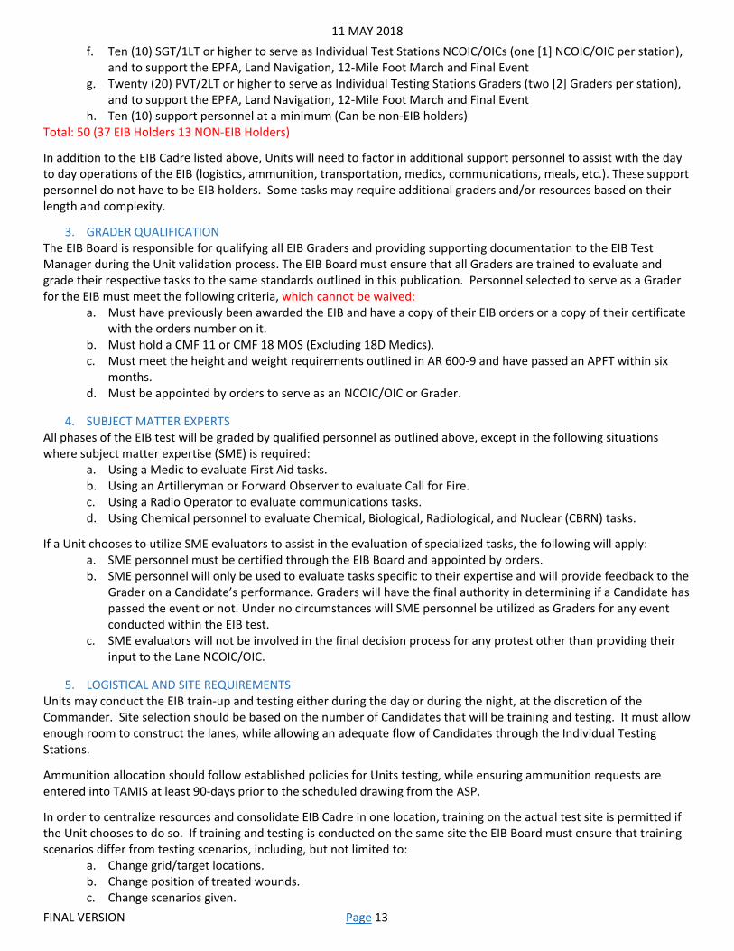
f. Ten (10) SGT/1LT or higher to serve as Individual Test Stations NCOIC/OICs (one [1] NCOIC/OIC per station), and to support the EPFA, Land Navigation, 12-Mile Foot March and Final Event
g. Twenty (20) PVT/2LT or higher to serve as Individual Testing Stations Graders (two [2] Graders per station), and to support the EPFA, Land Navigation, 12-Mile Foot March and Final Event
h. Ten (10) support personnel at a minimum (Can be non-EIB holders) Total: 50 (37 EIB Holders 13 NON-EIB Holders)
In addition to the EIB Cadre listed above, Units will need to factor in additional support personnel to assist with the day to day operations of the EIB (logistics, ammunition, transportation, medics, communications, meals, etc.). These support personnel do not have to be EIB holders. Some tasks may require additional graders and/or resources based on their length and complexity.
3. GRADER QUALIFICATION The EIB Board is responsible for qualifying all EIB Graders and providing supporting documentation to the EIB Test Manager during the Unit validation process. The EIB Board must ensure that all Graders are trained to evaluate and grade their respective tasks to the same standards outlined in this publication. Personnel selected to serve as a Grader for the EIB must meet the following criteria, which cannot be waived:
a. Must have previously been awarded the EIB and have a copy of their EIB orders or a copy of their certificate with the orders number on it.
b. Must hold a CMF 11 or CMF 18 MOS (Excluding 18D Medics). c. Must meet the height and weight requirements outlined in AR 600-9 and have passed an APFT within six
months. d. Must be appointed by orders to serve as an NCOIC/OIC or Grader.
4. SUBJECT MATTER EXPERTS All phases of the EIB test will be graded by qualified personnel as outlined above, except in the following situations where subject matter expertise (SME) is required:
a. Using a Medic to evaluate First Aid tasks. b. Using an Artilleryman or Forward Observer to evaluate Call for Fire. c. Using a Radio Operator to evaluate communications tasks. d. Using Chemical personnel to evaluate Chemical, Biological, Radiological, and Nuclear (CBRN) tasks.
If a Unit chooses to utilize SME evaluators to assist in the evaluation of specialized tasks, the following will apply: a. SME personnel must be certified through the EIB Board and appointed by orders. b. SME personnel will only be used to evaluate tasks specific to their expertise and will provide feedback to the
Grader on a Candidate’s performance. Graders will have the final authority in determining if a Candidate has passed the event or not. Under no circumstances will SME personnel be utilized as Graders for any event conducted within the EIB test.
c. SME evaluators will not be involved in the final decision process for any protest other than providing their input to the Lane NCOIC/OIC.
5. LOGISTICAL AND SITE REQUIREMENTS Units may conduct the EIB train-up and testing either during the day or during the night, at the discretion of the Commander. Site selection should be based on the number of Candidates that will be training and testing. It must allow enough room to construct the lanes, while allowing an adequate flow of Candidates through the Individual Testing Stations.
Ammunition allocation should follow established policies for Units testing, while ensuring ammunition requests are entered into TAMIS at least 90-days prior to the scheduled drawing from the ASP.
In order to centralize resources and consolidate EIB Cadre in one location, training on the actual test site is permitted if the Unit chooses to do so. If training and testing is conducted on the same site the EIB Board must ensure that training scenarios differ from testing scenarios, including, but not limited to:
a. Change grid/target locations. b. Change position of treated wounds. c. Change scenarios given.

11 MAY 2018
FINAL VERSION Page 14
Each station should strive to maximize changes to their scenario/information between: a. Practice and testing. b. Holding/retraining area and testing area. c. The two grading sites within one station. If a Candidate receives a NO-GO, the Candidate should retest
under a different Grader, and at the other site. More sites may be added if the Unit expects a backlog at that station, but there should be at least two different options and two different Graders.
Reference materials, training aids, and periods of instruction are permitted inside of the Holding Areas during EIB testing.
6. CANDIDATE ELIGIBILITY REQUIREMENTS Before being permitted to test for the EIB, prospective Candidates must meet the following requirements, which cannot be waived:
a. Must be an active member of the U.S. Army, ARNG, or USAR. b. Enlisted personnel must possess a CMF 11 or CMF 18 MOS as their primary MOS. Personnel holding the 18D
MOS are not eligible to test for the EIB. Secondary and additional Military Occupational Skills will not be considered in meeting this requirement.
c. Officers must be branch qualified as Infantry or Special Forces. Officers who are branch detailed to the Infantry may test for the EIB as long as they have completed the Infantry Officer Basic Course and are still assigned to the Infantry from the donor branch in accordance with AR 614-100.
d. Must meet all height and weight requirements outlined in AR 600-9. e. Must have qualified expert with the M4 Carbine or M16 Rifle on a 300 meter Automated Record Fire (ARF)
range within six months of testing for the EIB in accordance with FM 3-22.9. ARNG and USAR personnel must have qualified expert within one year of testing for the EIB. This prerequisite cannot be used to offset any testing requirements which occur within the EIB process. In instances where a 300 meter ARF range is not accessible to the Unit, qualification on the ALT-C course is acceptable; however, the Unit will need to justify their inability to access a 300 meter ARF range via memorandum to the EIB Test Manager. The waiver(s) must include the individual names, and be accompanied by their respective ARF scorecards (within one year), and ALT C qualification (within six months). Both must show that the Candidate qualified expert, scoring at least 36 points. This waiver must be approved prior to validation. ALT-C is not permitted in order to provide an additional attempt for weapons qualification for personnel who have been afforded an opportunity to qualify on a 300 meter ARF range prior to EIB testing.
f. Must have received the recommendation of their current Commander to participate in testing and have a reasonable expectation of passing all events.
g. In instances where a Unit is operating in conjunction with foreign allied forces, where a treaty or cooperative agreement exists, the senior Infantry Commander may extend an invitation to these forces to participate in the EIB process. Allied forces who participate in the EIB process must meet all established criteria within this manual to be considered an eligible Candidate, to include holding an equivalent Infantry primary MOS. Foreign forces not meeting these requirements cannot take part in any portion of the EIB process under any circumstance. Foreign forces will not be utilized as Graders or officials for the EIB process; however, designated foreign leadership should be present at every station to facilitate command and control of their troops as well as serve as translators. Allied personnel who successfully complete the EIB test to standard may be awarded the EIB Certificate, and the EIB in accordance with their prescribed uniform and award regulations.
h. Foreign soldiers are held to the same standards, with the following exemptions: 1. They must be qualified expert or expert equivalent within six months using their country’s process
and weapons. 2. They may qualify using the U.S. process and weapons. 3. They may qualify using the U.S. process, but their country’s weapons. 4. These same exemptions also apply to any foreign soldiers who meet the requirements for an ALT
C waiver.
At a Commander’s discretion, eligible Soldiers may be assigned or attached to a testing Unit for the sole purpose of participating in the EIB process when the parent Unit is not conducting a test.
11 MAY 2018
FINAL VERSION Page 15
Company Commanders, or equivalent, are responsible for certifying that their Soldiers meet all eligibility requirements to test for the EIB and are required to provide a roster of their Candidates, with supporting documentation, to the EIB Board. In order to maintain the integrity of the test, an approved sworn statement by each Battalion Commander or higher must be submitted to the EIB Test Manager during the validation process.
7. MEDICAL PROFILES Personnel who have received a permanent medical profile may test for the EIB as long as their profile will not prevent them from taking part in any of the required events.
8. GRADING PROCEDURES Candidates must successfully complete all phases of the EIB test to standard in order to receive the award. Candidates are required to pass all 30 Individual Testing Stations. Any attempt to intentionally bypass an Individual Testing Station, or any other integrity violation will result in immediate elimination from the EIB process.
Any unsafe act committed by a Candidate during any phase of testing will result in immediate elimination from the EIB process. The EIB Board should clearly define what constitutes an unsafe act, and ensure all Graders and Candidates receive a briefing before training begins.
During all phases of testing, Candidates are evaluated by a Grader who observes the Candidate. Graders are accountable to either an Individual Testing Station NCOIC/OIC or a Lane NCOIC/OIC during all phases of testing. Lane NCOIC/OICs have overall responsibility and authority for their lane, to include final appeal/protest authority.
Candidates are eliminated from EIB under the following grading criteria: a. Failing to pass any big event (EPFA, Day/Night Land Navigation, 12-Mile Foot March, and Final Event). b. Receiving more than one NO-GO within one lane over the course of the 30 Individual Testing Stations.
(Candidates are allowed three total NO-GOs/retests; one per lane.) c. Failing to return for a retest within one hour. d. Any unsafe act or integrity violation.
9. OPERATIONS During the train-up and testing phases, all operations should be coordinated through a consolidated EIB operations center under the supervision of an Operations NCOIC/OIC appointed through orders by the EIB Board. The Operations NCOIC/OIC is responsible for consolidating and maintaining all Candidate packets and score sheets throughout all phases of testing. The NCOIC/OIC is required to submit all required spreadsheets, trackers, statistics, and other documentation to the EIB Test Manager at the end of each day, and at the conclusion of testing. The final tracker should include all Candidates who did not start/complete testing due to prerequisites, event failures, and/or administrative drops.
10. CANDIDATE PACKETS The EIB Board is responsible for determining the content and format of Candidate packets, ensuring to provide any requested documentation to the EIB Test Manager.

11 MAY 2018
FINAL VERSION Page 16
Chapter 3-Pre-Execution Phase
1. UNIT PREPARATION Commanders should integrate EIB test events and subjects into individual and collective training programs at least 120-days prior to EIB execution. Sustainment training for physical fitness and land navigation will greatly improve the overall outcome of the EIB test success rate. In addition, it is highly recommended for Commanders to allocate sufficient squad level training focused on EIB tasks to ensure Soldiers are properly prepared.
The scheduled train-up period integrated into the EIB process is not designed to instill a level of proficiency to successfully pass the EIB test. This train-up period serves as an indicator for the EIB Board to identify problems with their test execution. This offers an opportunity to make slight adjustments prior to test execution, while providing the Candidates an understanding of how the test will be run.
The EIB Board must print an EIB book for all Candidates/Cadre. The USAIS PAM 350-6 is the only authorized resource for obtaining this information for the EIB test, which ensures a uniform standard throughout the force. The USAIS PAM 350-6 can be found on the EIB website; www.benning.army.mil/infantry/eib
Efforts should be made to conduct all EIB training under the same conditions that the test will be administered.
2. GRADER PREPARATION The EIB Board is responsible for training and certifying all Graders and EIB Cadre personnel. This process should take place concurrently with the Unit train-up phase 120-days prior to EIB execution. All Graders and Cadre should be trained and certified by the EIB Board prior to the EIB Test Manager validation of the EIB test site. Training and certification of these personnel should ensure the following at a minimum:
a. A complete understanding of all events and tasks that will be tested. b. A knowledge of the timeline for the entire EIB process. c. A complete understanding of their specific roles in the EIB process; grading standards, requirements, and re-
test procedures for their specific areas of responsibility. d. Trained in all administrative requirements. e. Trained in the appeals process. f. A complete understanding of all safety and risk mitigation requirements for all phases of testing.
Training and certification of Graders and Cadre should require them to demonstrate their proficiency in their areas of responsibility through practical demonstration to the EIB Board. These personnel should be placed in positions where they will rotate through the various positions that they will serve in, scoring and performing the tasks they are responsible for. The EIB Board should designate Role-Players to act as Candidates for personnel to grade and interact with. These Role-Players should intentionally execute tasks incorrectly to ensure Graders and Cadre fully understand the standards and are able to properly assess Candidates. The NCOIC/OIC for each Individual Testing Station/Lane must be present for this process as their personnel are certified.
All Graders and Cadre need to demonstrate to the EIB Board their ability to perform all required actions to standard within their Individual Testing Stations in order to be considered qualified. Personnel who successfully accomplish this are considered to be certified for that EIB iteration only.
3. EIB TRAIN-UP For Active Duty Units, or Mobilized ARNG and USAR Units, the EIB train-up typically lasts a minimum of one week leading into the EIB test, unless a Unit has established an alternate train-up schedule.
Authorized ARNG and USAR Units that are in a non-mobilized status and conduct traditional M-day or TPU training may conduct EIB as follows:
a. Complete the train-up over two consecutive Inactive Duty Training (IDT) periods consisting of at least nine Mandatory Unit Training Assemblies (MUTA). Complete the test over the next consecutive five day MUTA-9 IDT period.
b. Complete the train-up and test (test will be five consecutive days) over two consecutive IDT periods consisting of at least nine MUTAs each.

11 MAY 2018
FINAL VERSION Page 17
c. Complete the train-up and test (test will be five consecutive days) over 14 consecutive days during their authorized Annual Training (AT) period.
d. Complete the train-up over the five day MUTA-9 IDT period immediately prior to Annual Training and testing must be completed over a five day period, within the first eight days of AT.
e. Complete the train-up over two consecutive Inactive Duty Training (IDT) periods consisting of at least nine MUTAs immediately prior to AT. Testing must be completed over a five day period, within the first eight days of AT.
f. Complete the train-up over the last eight days of AT and conduct the test during the first five day MUTA-9 IDT period immediately following AT.
Training can be centralized on the actual EIB site or conducted in a decentralized manner at the company level at the discretion of the EIB Board. This is the only train-up period specifically required for EIB testing; however, Units should not rely on this train-up alone.
During the train-up phase Candidates are permitted to use the existing land navigation site that will be used for testing; however, lanes and points need to be changed for the actual EIB test. All efforts and control measures need to be put in place to ensure Candidates are not testing on any of the same points they practiced on and are not able to create a “cheat sheet” for the course. Whenever possible, lanes should be set aside for practice only with the understanding that those lanes will not be used for testing.
During the train-up phase it is not necessary to use the Graders or Cadre as the primary instructors on the training site. Emphasis should be placed on having team leaders and squad leaders preparing and training their Soldiers for the test, with Graders, SMEs, and Cadre observing and making corrections as needed. The EIB Board is responsible for ensuring that personnel tasked with instructing Candidates at this point are knowledgeable, and certified to instruct their specific tasks.
All required equipment and training aids should be present and in working condition for use by Candidates during the train-up phase. Equipment requirements are dependent on the number of Candidates testing. The primary responsibility of the Graders and Cadre at this point is to ensure all tasks are being executed properly according to the established standards within this manual, while addressing any issues, questions, or concerns from the Candidates in regards to expectations and test requirements.
The EIB Board has the discretion to determine the manner in which the train-up phase is conducted. The key to the train-up phase is that the Candidates are left with no questions regarding the manner in which they will test and that all tasks have been instructed in accordance with the specified Task, Conditions and Standards outlined in this manual.
4. TEST VALIDATION Units should be prepared to have the EIB Test Manager present a week prior to the train-up phase for the purpose of test validation and issuing of the TCN; however, this time frame is flexible and can be coordinated directly with the EIB Test Manager based on his/her availability determined by other Unit’s test schedules. Test validation may occur concurrently with the train-up with minimal interference; however, during the validation, Units have to have all training areas, lanes and Individual Testing Stations constructed and accessible for the EIB Test Manager.
During validation, Units should be prepared to make slight adjustments to their test execution plan based on input from the EIB Test Manager. Maintaining open lines of communication with the EIB Test Manager during all test preparation will help minimize final changes to the test execution. A TCN will only be issued after the EIB Test Manager has validated the entire test site.
Land navigation test lanes will be off limits to all Candidates once the EIB Test Manager has validated the site. Candidates may continue to have access to the EPFA route, 12-Mile Foot March route, Individual Testing Stations, and practice land navigation lanes after the EIB Test Manager’s validation has been completed as these test requirements are already a known factor to the Candidates.
After validation no additional Candidates may be added to the roster.

11 MAY 2018
FINAL VERSION Page 18
5. TIME LINE Using the following time line for a two week train-up as a guide, with T-Day representing Test Day 1, Units should be prepared to execute EIB train-up and testing as follows:
a. T-14 Train-up Day 1 b. T-13 Train-up Day 2 c. T-12 Train-up Day 3 d. T-11 Train-up Day 4 e. T-10 Train-up Day 5 f. T-9 Commander’s Time g. T-8 Commander’s Time h. T-7 Train-up Day 6 i. T-6 Train-up Day 7 j. T-5 Train-up Day 8 k. T-4 Train-up Day 9 l. T-3 Train-up Day 10 m. T-2 Commander’s Time n. T-1 Commander’s Time o. T-Day Test Day 1: EPFA and Land Navigation p. T+1 Test Day 2: Individual Testing Stations q. T+2 Test Day 3: Individual Testing Stations r. T+3 Test Day 4: Individual Testing Stations s. T+4 Test Day 5: 12-Mile Foot March and associated tasks, and Award Ceremony
Using the following time line for a one week train-up as a guide, with T-Day representing Test Day 1, Units should be prepared to execute EIB train-up and testing as follows:
a. T-7 Train-up Day 1 b. T-6 Train-up Day 2 c. T-5 Train-up Day 3 d. T-4 Train-up Day 4 e. T-3 Train-up Day 5 f. T-2 Commander’s Time g. T-1 Commander’s Time h. T-Day Test Day 1: EPFA and Land Navigation i. T+1 Test Day 2: Individual Testing Stations j. T+2 Test Day 3: Individual Testing Stations k. T+3 Test Day 4: Individual Testing Stations l. T+4 Test Day 5: 12-Mile Foot March and associated tasks, and Award Ceremony
While the entire EIB process is intended to be executed over 14 consecutive days when using a one week train-up period or a maximum of 19 consecutive days when using a two week train-up period, Units have the discretion to transition from Train-up Day 5 (T-3) directly into Test Day 1 (T-Day). Units may use the two days of Commander’s Time for study groups, Sergeant’s Time, refresher training, administrative time, pass, etc. Testing must begin no more than three days after the completion of the official train-up phase. Without exception, testing will be conducted over five continuous days beginning with the EPFA on Test Day 1 and ending with the 12-Mile Foot March and Final Event on Test Day 5. This time line reflects all Candidates conducting the EPFA and land navigation in one mass group on Test Day 1 (T-Day); however, the EIB Board may elect to break the Candidates down into four groups on Test Day 1 after the EPFA with groups rotating through the Land Navigation, Weapons, Medical, and Patrol Lanes over Test Days 1 through 4 (T-Day through T+3).

11 MAY 2018
FINAL VERSION Page 19
Chapter 4-Phase One: The EIB Physical Fitness Assessment
1. CONCEPT The EPFA is the first graded event of the EIB test. Candidates are required to perform 49 push-ups in two minutes, 59 sit-ups in two minutes, and a four mile run in 32 minutes. This is a GO or NO- GO event which must be passed in order for a Candidate to remain in the EIB process. There will be no re-test for any Candidates who fail the EPFA and this event cannot be waived.
2. CONDITIONS The EPFA should be administered in the same fashion as an Army Physical Fitness Test (APFT), based on the standards outlined in FM 7-22. The only difference will be the amount of push-ups and sit-ups required and the length of the run. While Units can allow Candidates to execute push-ups and sit-ups beyond the minimum requirements, they may also stop Candidates once the minimum has been reached, as this will reduce the time required to test all Candidates.
Candidates who fail any event should be stopped immediately, and directed to a different holding area to be processed for elimination from the EIB test.
Units should ensure that the EPFA site complies with current APFT regulations. The site must be well lit to facilitate grading and control, and the four mile run route must be clearly marked. An adequate number of medical personnel and safety vehicles must be available, and proper risk management incorporated into the event.
3. STANDARDS This event constitutes Phase One of the EIB test and may only be graded by EIB Cadre. It is the responsibility of the EIB Board to ensure all Graders for this event are grading to the same standard without variance. The EIB Board will establish this standard in accordance with existing regulations.
Candidates are required to pass each event; failing to do so will result in a NO-GO, and the Candidate will be eliminated from the EIB test. Candidates failing this task should be segregated in a separate holding area until they can be processed by the NCOIC/OIC, followed by the EIB NCOIC/OIC for out-processing. No Candidate who fails the EPFA will progress to Phase Two.
11 MAY 2018
FINAL VERSION Page 20
Chapter 5-Phase Two: Land Navigation
1. CONCEPT This event constitutes Phase Two of the EIB test and may only be graded by EIB Cadre. It is the responsibility of the EIB Board to ensure all Graders for this event are grading to the same standard without variance. The EIB Board will establish this standard in accordance with existing regulations and doctrine.
During this phase Candidates will demonstrate their individual proficiency in navigating from one point to another while dismounted without the aid of electronic navigation devices. Candidates must pass both day and night land navigation iterations in order to receive a GO for this event. Failing land navigation will result in a NO-GO, and eliminate the Candidate from the EIB test. This event is not re-testable.
2. CONDITIONS Candidate Conditions Candidates will be provided a 1:50,000-scale military topographic map, a lensatic compass, protractor (GTA 05-02-012), a writing instrument, a score sheet, and a list of designated points that they have to find. Units should ensure that a compass calibration site has been established for the Candidates to verify the accuracy of their compass before they begin the land navigation course. Candidates will complete both day and night iterations while in the EIB uniform designated by the EIB Board.
Candidates will be checked upon arrival at the land navigation course to ensure they have no cell phones, GPS devices, or other electronic equipment that may be used to assist them during this phase of testing. If the Unit desires that the Candidates have a cell phone for safety reasons, they should be turned off and sealed inside a non-transparent, official mailing envelope, evidence bag, etc.
Land Navigation Course Conditions The navigation course utilized for train-up and testing must have had all points validated through a site survey conducted by an Engineer or Field Artillery Unit. If a Unit is unable to use a validated course, or unable to obtain Engineer or Field Artillery support in order to validate a new course, validation may be accomplished by using approved military issued GPS devices as follows:
a. Use a minimum of two GPS devices to obtain a minimum of a ten-digit grid for each point, with no more than a 20 meter variance between readings from each device.
b. All GPS devices used in the validation of the course must be the same model. For example, using a DAGR and a PLGR together in order to validate a course would not be acceptable due to the accuracy differences of each different model.
c. Courses will not be validated with civilian GPS models under any circumstances. d. Unit will make all efforts to use two different land navigation courses, one for train-up and another for
testing. If the same land navigation course is used the Unit will need to change the location of all points prior to testing.
The EIB Board is responsible for certifying the navigation course prior to the start of the train-up phase and again before testing. Certification differs from the validation process and consists of having designated EIB Cadre negotiate each lane of the course in order to confirm the following:
a. All points are present in the designated locations. b. Each point is in good condition and has a reasonable expectation of being located. c. The validation parameters from previous surveys remain in effect. d. All points are equipped with a unique navigation punch to ensure Candidates were physically at the point.
Land navigation lanes will consist of a known release point, four navigation points, and a known end point; all within the boundaries of the navigation site. Units may create as many release points as necessary based on the number of lanes/Candidates, or may utilize a staggered start time. The release point and end point may be the same. The distance between navigation points will be 800-1000 meters during the day, and 600-800 during the night. The overall distance of a navigation lane will not exceed 4500 meters during the day, and 3500 during the night. The total includes the distance traveled from the Release Point to the End Point, where score sheets are collected and a Candidate’s time is

11 MAY 2018
FINAL VERSION Page 21
recorded. At the discretion of the EIB Board, navigation points may be marked at night with reflective material. The Unit will not use a self-correcting navigation course during EIB testing; no points will have any identifying grid locations on them. The points must be clearly visible, free of obstructions, within at least a 10 meter radius. All grid locations will be given in a 10 digit format. No Candidate will have any of the same points during testing that they had during training. The NCOIC must have a spreadsheet that clearly shows all the requirements outlined in this paragraph; this spreadsheet will be inspected during validation.
Day navigation will be conducted after sunrise and conclude before End of Evening Nautical Twilight (EENT) for the region that testing is conducted in. Night navigation will be conducted after EENT and conclude before sunrise for the region that testing is conducted in.
3. STANDARDS The following standards will apply for all Candidates conducting the land navigation course:
a. Candidates will stage at a known release point after they have received their points, course orientation brief, and safety brief. At the direction of the land navigation NCOIC/OIC, Candidates will be given the signal to start and official timing will begin. Units may utilize a staggered release plan in order to provide better control and reduce congestion within the navigation course.
b. Candidates will record the alpha numeric identification for each of their navigation points as well as punching their score card with the unique punch provided at each point.
c. Candidates will have three hours to correctly locate three out of four of the navigation points on their lane, return to the end point, and report to the designated EIB Cadre. Upon reporting to the EIB Cadre the Candidate’s completion time will be recorded on the score card. At this point Candidates will be considered as having completed their attempt and will not be permitted to re-enter the course, even if they have returned before their allotted time has expired.
d. Candidates will receive a NO-GO for land navigation under the following circumstances: 1. Failing to find and properly record at least three of their navigation points. 2. Failing to properly punch their score card for each navigation point. 3. Failing to complete the course in three hours or less. 4. Not having their map or score card with them when reporting to the end point.
Candidates failing this task should be segregated in a separate holding area until they can be processed by the NCOIC/OIC, followed by the EIB NCOIC/OIC for out-processing. No Candidate who fails land navigation will continue with Phase Three.
11 MAY 2018
FINAL VERSION Page 22
Chapter 6-Phase Three: Individual Testing Stations
1. CONCEPT Individual Testing Stations are used to evaluate a Candidate’s proficiency with tasks common to an Infantry Unit. Individual Testing Stations are performance based. Candidates are required to execute each task to an established set of standards within a specified period of time. Candidates must pass all Individual Testing Stations. Candidates who fail to meet the standards for the Individual Testing Stations will be eliminated from the EIB process. See Chapters 10-12 for Individual Testing Stations performance measures.
2. CONDITIONS Individual Testing Stations will be executed inside the established three lanes (Weapons, Medical, and Patrol). There should be adequate distance inside the established lanes to execute all Individual Testing Stations. In order to facilitate Candidate throughput, Units should plan on establishing multiple sub-stations inside of each Individual Testing Station based on Unit numbers of EIB Candidates.
Each Individual Testing Station should be established with the following at a minimum: a. Authorized stopwatches for timing Candidates. b. All required weapon systems and equipment for each selected task. c. Adequate lighting, overhead cover, ground cloth, and field tables if needed. d. Dividers that prevent Candidates from observing each other while testing. e. Adequate number of spreadsheets/scoresheets and administrative materials. f. Adequate safety requirements. g. Minimum of two Graders and an NCOIC/OIC. h. Copies of all Tasks, Conditions, Standards, and performance measures for all Graders. i. Appropriate signage. j. All Tasks, Conditions, Standards, and performance measures printed on large poster board in holding area. k. All associated ATN tasks and any applicable resources in holding area.
3. TESTING On Test Days 2 through 4 (T+1 through T+3), Candidates will assemble at their appointed lane and receive a brief from the Lane NCOIC/OIC. Candidates must complete all 10 Individual Testing Stations within their assigned lane for that day. Upon instruction from the Lane NCOIC/OICs, Candidates will proceed from the lane holding area to the Individual Testing Stations. All Candidates will check in and out through their respective Lane NCOIC/OICs before reporting to the TOC NCOIC/OIC for turn in of their individual score sheet.
Each lane should have a logical, orderly flow, and each station will be appropriately labeled at both the holding and testing areas. The holding areas must include all of the resources required at the testing station to ensure Candidate success during training and/or retraining.
The EIB Board is responsible for establishing the uniform requirements for all phases of testing. It should be realistic, combat-focused, in accordance with the testing Unit’s Standard Operating Procedures, and include the appropriate personal protective equipment.
Grading Prior to testing, the Candidates should already be familiar with the Tasks/Conditions/Standards and any special instructions for that station. Once the Candidates arrive at the Individual Testing Stations, the Grader will state the following: “I am (Rank and Name), and will be your Grader for Individual Testing Station (insert the Individual Testing Station task). I will be evaluating you during this phase of testing. Do you have any questions before you begin?”
After this introduction the Grader will provide additional guidance and/or directions to the Candidate specific to that Individual Testing Station. Graders must read all Tasks, Conditions, and Standards to the Candidate prior to beginning each Individual Testing Station. The Grader will then ask the Candidate if they have any questions; the Grader may repeat all instructions/guidance, but must not provide any additional information. The Grader will then show the Candidate that the stopwatch is at 0:00, wait five seconds and say, “begin”. If the Candidate finishes early, the Grader should state, “Candidate, you have more time”. If the Candidate confirms they are complete, the Grader should stop
11 MAY 2018
FINAL VERSION Page 23
the time and give the Candidate their grade. All Graders will ensure to use the same procedures to start and stop the task for all Candidates at their station.
All Individual Testing Station tasks will be conducted in accordance with the Tasks, Conditions and Standards listed in this publication. It has been designed to allow Units to readily reproduce the Tasks, Conditions, and Standards for use during EIB train-up and testing.
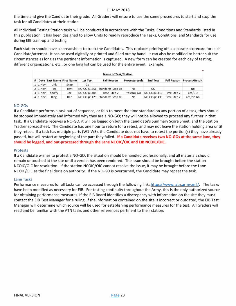
Each station should have a spreadsheet to track the Candidates. This replaces printing off a separate scorecard for each Candidate/attempt. It can be used digitally or printed and filled out by hand. It can also be modified to better suit the circumstances as long as the pertinent information is captured. A new form can be created for each day of testing, different organizations, etc., or one long list can be used for the entire event. Example:
NO-GOs If a Candidate performs a task out of sequence, or fails to meet the time standard on any portion of a task, they should be stopped immediately and informed why they are a NO-GO; they will not be allowed to proceed any further in that task. If a Candidate receives a NO-GO, it will be logged on both the Candidate’s Summary Score Sheet, and the Station Tracker spreadsheet. The Candidate has one hour to return for a retest, and may not leave the station holding area until they retest. If a task has multiple parts (W1-W5), the Candidate does not have to retest the portion(s) they have already passed, but will restart at beginning of the part they failed. If a Candidate receives two NO-GOs at the same lane, they should be logged, and out-processed through the Lane NCOIC/OIC and EIB NCOIC/OIC.
Protests If a Candidate wishes to protest a NO-GO, the situation should be handled professionally, and all materials should remain untouched at the site until a verdict has been rendered. The issue should be brought before the station NCOIC/OIC for resolution. If the station NCOIC/OIC cannot resolve the issue, it may be brought before the Lane NCOIC/OIC as the final decision authority. If the NO-GO is overturned, the Candidate may repeat the task.
Lane Tasks Performance measures for all tasks can be accessed through the following link: https://www. atn.army.mil/. The tasks have been modified as necessary for EIB. For testing continuity throughout the Army, this is the only authorized source for obtaining performance measures. If the EIB Board identifies a discrepancy with information on the site they must contact the EIB Test Manager for a ruling. If the information contained on the site is incorrect or outdated, the EIB Test Manager will determine which source will be used for establishing performance measures for the test. All Graders will read and be familiar with the ATN tasks and other references pertinent to their station.
# Date Last Name First Name 1st Test Fail Reason Protest/result 2nd Test Fail Reason Protest/Result1 1-Nov Link Snap Go2 1-Nov Peg Tent NO GO@1356 Standards-Step 1B No GO No3 1-Nov Snuffy Joe NO GO@1405 Time- Step 2 Yes/NO GO NO GO@1410 Time-Step 2 Yes/GO4 1-Nov Ring Dee NO GO@1429 Standards-Step 1C No NO GO@1439 Time-Step 2 Yes/No Go
Name of Task/Station

11 MAY 2018
FINAL VERSION Page 24
Chapter 7-Phase Four: 12-Mile Foot March and Final Event
1. CONCEPT The final phase of the EIB test is the 12-mile Foot March and Final Event. The Foot March is executed in accordance with the guidance listed in this publication and FM 21-18. All Candidates must successfully complete the 12-mile Foot March in three hours or less, immediately followed by the Final Event within five minutes or less. See Chapter 13 for the Final Event performance measures. The 12-mile Foot March and Final Event is a GO or NO-GO event and is not re-testable.
2. CONDITIONS The Foot March may be executed during the day or at night at the discretion of the EIB Board and the Unit Commander. The Foot March route must be 12 miles in length, clearly marked, and easily identifiable by the Candidates. The length of the route must be verified through the use of a calibrated distance measuring wheel. If a calibrated measuring wheel is not available then the course can be verified by using the average odometer reading taken from three different vehicles.
Route selection needs to include consideration for ease of movement, consistent terrain features, and no obstructions along the route that would require the Candidates to maneuver around. The slope of the terrain should be similar in nature to the terrain that the Candidates had been conducting their conditioning and training on. Units should take every effort to plan the Foot March along a route closed to vehicular traffic; however, if this is not possible, positive safety control measures need to be put in place to ensure Candidates are protected from vehicles. Units will ensure that medics are stationed along the route, ambulances are available, and that safety vehicles are used along the route during this event.
If the route requires a turn-around point, it must be easily recognizable by the Candidates. It must allow the Candidates to turn around without impeding each other or causing congestion. Units need to establish control measures along the route, including turns and turn-around points, to ensure Candidates remain on the route.
Water points need to be established along the route with reasonable distance between each water point. At a minimum, water should be available every three miles along the route.
Units will ensure there are at least two official timing devices which have been calibrated for the Foot March. While it is not required, Units are encouraged to provide the Candidates with the elapsed time when they reach the six-mile point of the Foot March. The time from the official clock will be the only time used to officiate this event.
3. STANDARDS Candidates must carry 35 pounds of dry weight in their ruck-sack over the entire course of the Foot March. This weight is in addition to their personal equipment and water, which is worn and carried evenly distributed over their bodies. Units must have a calibrated scale at the end of the course to ensure that the Candidates finish the event with the required weight in their ruck-sack or the Unit conducts a layout of the required packing list totaling 35 pounds. Any Candidate who finishes with less than the required 35 pounds of dry weight in their ruck-sack or missing a piece of equipment from the layout will be eliminated from the EIB process, even if they completed the Foot March within the required time. The scales must be available to the Candidates at least one day prior to the Foot March. The 12-mile Foot March must be executed in the EIB uniform with approved boots. Units may add additional equipment at the direction of the EIB Board and Commander.
11 MAY 2018
FINAL VERSION Page 25
Chapter 8-Awarding the Expert Infantryman Badge and Streamer
1. CRITERIA Candidates who pass all phases of the EIB test will be awarded the Expert Infantryman Badge, Orders, and a Certificate. Units should ensure that the awarding of the Expert Infantryman Badge occurs during a suitable public ceremony as soon as possible after receiving award orders and certificates from USAIS. Announcement for the award of the EIB is in accordance with AR 600-8-105.
To ensure standardization throughout the Army, Units are required to present the USAIS EIB certificate as the official certificate to accompany the badge and orders. Units are discouraged from awarding a certificate of their own design in addition to the USAIS certificate, as it will not be accepted as proof of earning an EIB. For tracking and verification purposes, the corresponding order number from the orders will be recorded on the EIB certificate by USAIS.
It is the responsibility of the testing Unit to ensure individual Enlisted and Officer Records Briefs are properly updated to reflect the award of the EIB, as well as ensuring a copy of the orders are uploaded into each recipient’s Official Military Personnel File (OMPF).
2. EXPERT INFANTRY STREAMER In accordance with AR 600-8-22, paragraph 7-4, the Expert Infantry Streamer is awarded to an Infantry Company; Infantry Battalion; Infantry Brigade; or a separate Infantry Platoon when at least 65% of the assigned strength has earned the EIB during an EIB testing period.
Once awarded, the receiving Unit can display the Expert Infantry Streamer for a period of 12 months on their Unit colors or guidon. The Streamer must be removed at the end of the 12 month period from when it was awarded.
The Expert Infantryman Streamer consists of the following: a. Size: The Expert Infantry Streamer measures 1 inch wide by 24 inches long (from the flagstaff to the end of
the swallowtail) with a 1 1/2inch fork. This streamer must be ordered and purchased through the individual Unit supply channel from either the GSA catalog or utilizing other local purchase options.
b. Color: The Expert Infantry Streamer is white with blue embroidered lettering indicating the level of recognition as follows:
1. Expert Infantry Brigade 2. Expert Infantry Battalion 3. Expert Infantry Company 4. Expert Infantry Platoon
Commanding Generals may award the Expert Infantry Streamer to separate Infantry Brigades, Battalions, or Platoons under their command. Commanders of Infantry Battalions or Brigades may award the Expert Infantry Streamer to Infantry Companies under their command. When awarding the Expert Infantry Streamer, Commanders should cite this publication as the appropriate authority for the award.

11 MAY 2018
FINAL VERSION Page 26
Chapter 9-Post Test Requirements
The testing Unit will submit an After Action Report (AAR) within 15 days of completion of the EIB process utilizing the format provided by the EIB Test Manager. Any issues that were identified during the EIB process should be resolved during this period.
Information from the AARs will be used for statistical purposes in regards to training and identifying trends across the force. In addition, the AAR information will assist in determining the relevancy of the EIB process and aid in making updates to the test process as needed. Units planning an EIB test are highly encouraged to review previous AARs to improve the efficiency of their own event. Under no circumstances will AAR information be used in assessing any Unit or command capabilities, as the EIB process is designed to test individual abilities only.
It is highly recommended that Units retain all EIB materials upon completion of the test process in order to establish continuity for future EIB tests conducted within the Unit. Units who conclude the EIB process are encouraged to continually share information with other Units concerning the EIB test.
Commanders must follow up with their appropriate S-1 staff to ensure that the records for all Soldiers who received their EIB were properly updated to reflect this award.

11 MAY 2018
FINAL VERSION Page 27
Chapter 10-Weapons Lane
W1: Rifle/Carbine and Light Grenade Launcher Part One-M4/M16 Rifle/Carbine Based on: 071-COM-0032-Maintain an M16-Series Rifle/M4-Series Rifle Carbine 071-COM-0028-Load an M16-Series Rifle/M4-Series Carbine 071-COM-0033-Correct Malfunctions of an M16-Series Rifle/M4-Series Carbine 071-COM-0027-Unload an M16-Series Rifle/M4-Series Carbine
Task: Clear, load, fire until a stoppage occurs, perform immediate action, expend remaining ammunition, unload and clear an M4/M16.
Condition: You are a member of a squad or team conducting dismounted operations. You have a stoppage while engaging targets with your carbine.
Standard: Correctly perform all steps, in sequence, in 30 seconds or less.
Requirements: An M16/M4 carbine with blank adaptor and sling. Starting configuration for the weapon will be: free of ammunition, bolt forward, on FIRE (SEMI/BURST/AUTO), and the trigger pulled. A magazine loaded with four blank rounds of ammunition and one inert/expended round. A target/safe direction for the Candidate to engage. Hearing protection (part of the EIB uniform) must be worn when firing.
Candidate will start with the weapon in the low ready. 1. Clear the weapon.
a. Keep the weapon pointed in a safe direction. b. Attempt to place the weapon on SAFE. c. Ensure chamber is clear.
1. Pull the charging handle to the rear. 2. Check the chamber to ensure it is clear.
Note: The chamber can be checked either by locking the bolt to the rear or by holding the bolt to the rear and then observing the chamber area.
3. Return the charging handle to the forward position. d. Place weapon on SAFE. e. Lock the bolt to the rear (If not done in step b).
1. Pull the charging handle rearward. 2. Press and hold the bottom of the bolt catch. 3. Allow the bolt to move forward until it engages the bolt catch. 4. Release the bottom of the bolt catch. 5. Return the charging handle to the forward position.
2. Load the weapon a. Insert the magazine.
Note: Round may be chambered with the bolt assembly open or closed. 1. Push the magazine upwards until the magazine catch engages. 2. Tap upward on the bottom of the magazine to ensure the magazine is seated.
b. Chamber a round. 1. Chamber a round when the bolt is open.
Note: The bolt should not be ridden forward. a. Press the upper portion of the bolt catch allowing the bolt to go forward b. Tap the forward assist to ensure that the bolt is fully forward and locked. c. The weapon is now loaded.
2. Chamber a round when the bolt is closed. Note: The bolt should not be ridden forward.

11 MAY 2018
FINAL VERSION Page 28
a. Pull the charging handle to the rear as far as it will go. b. Release the charging handle. c. Tap the forward assist to ensure that the bolt is fully forward and locked. d. The weapon is now loaded.
3. Place the weapon on SEMI and begin engaging your target. 4. Perform immediate action.
Note: The key word "SPORTS" will help you remember the steps for immediate action in sequence; slap, pull, observe, release, tap, shoot.
a. Slap upward on the magazine to ensure it is fully seated and that the magazine follower is not jammed. b. Pull the charging handle fully to the rear. c. Observe the ejection of a live round or expended cartridge.
Note: If a weapon fails to eject a cartridge, perform remedial action. d. Release the charging handle; do not ride the charging handle. e. Tap the forward assist to ensure that the bolt is closed. f. Squeeze the trigger.
Note: Weapon should fire. If weapon does not fire, proceed to remedial action (for this task, move to clear the weapon).
5. Clear the weapon. a. Point weapon in safe direction. b. Attempt to place the weapon on SAFE. c. Remove the magazine from the weapon. d. Lock the bolt open (if not already).
1. Pull the charging handle rearward. 2. Press the bottom of the bolt catch. 3. Move the bolt forward until it engages the bolt catch. 4. Return the charging handle to the forward position. 5. Ensure the receiver and chamber are free of ammo.
e. Place the weapon on safe (if not already). f. Press the upper portion of the bolt catch to allow the bolt to go forward. g. Close the ejection port cover.
11 MAY 2018
FINAL VERSION Page 29
Part Two-Light Grenade Launcher Based on: 071-031-0002-Load an M320 Grenade Launcher 071-031-0003-Unload an M320 Grenade Launcher 071-COM-2127-Load an M203 Grenade Launcher 071-COM-2128-Unload an M203 Grenade Launcher Task: Clear, load, unload, and clear an M320 Grenade Launcher
Condition: You are a member of a squad or team conducting dismounted operations. You have been directed to load the M320.
Standard: Correctly clear and load the grenade launcher in 15 seconds. Correctly unload and clear the grenade launcher in 15 seconds. You must not drop the 40-mm ammunition. All tasks will be performed in sequence.
Requirements: An M320/M203 Grenade Launcher; may be attached to the same rifle used in Part 1. A target/safe direction for the Candidate to engage and a dummy/training round. If the EIB uniform does not include a grenade pouch, the station should provide appropriate load bearing equipment to properly secure the grenade. Use the appropriate set of standards based on the weapon system being used:
M320 Clear and Load: Candidate will start with the weapon in the low ready and the grenade secured in the appropriate pouch. 1. Point the weapon in a safe direction. 2. Ensure weapon is on SAFE. 3. Press barrel release and pivot barrel out from receiver. 4. Make sure the bore and chamber is clear of round or spent cartridge. 5. Insert a single round of ammunition into the barrel. 6. Ensure cartridge is seated fully forward in rear of barrel. 7. Pivot barrel into receiver until barrel locking lever engages barrel.
Note: There should be an audible click when the barrel locking lever engages barrel.
Unload and Clear: Candidate will start from the last position in the previous task. 1. Keep the weapon pointed in a safe direction, with trigger finger outside trigger guard. 2. Ensure weapon is on SAFE. 3. Press upward on barrel release lever and pivot barrel out from receiver. 4. Remove any round or cartridge case by hand.
a. Grasp rim of round or cartridge case. b. Pull rearward to remove round or cartridge case from the barrel.
5. Pivot barrel into receiver until barrel release lever engages barrel. 6. Ensure weapon is still on SAFE. 7. Secure the round as per Unit standing operating procedure (SOP)/Grader guidance.
M203 Clear and Load: Candidate will start with the weapon in the low ready and the grenade secured in the appropriate pouch. 1. Point the weapon in a safe direction. 2. Ensure the safety is in SAFE position. 3. Depress the barrel latch. 4. Slide the barrel assembly forward. 5. Make sure the bore and chamber is clear of round or spent cartridge. 6. Insert a single round of ammunition into the chamber. 7. Slide the barrel closed until it locks.
Note: When the barrel locks, you will hear a click.

11 MAY 2018
FINAL VERSION Page 30
Unload and Clear: Candidate will start from the last position in the previous task. 1. Point the weapon muzzle in a safe direction. 2. Attempt to place the safety in the "S" position.
Note: If M203 is not cocked, the lever cannot be placed on SAFE ("S" position). 3. Remove the round from the M203.
a. Depress the barrel latch. b. Place one hand under the barrel assembly forward of the trigger guard. c. Slowly slide barrel assembly forward.
Note: The round will begin to eject. 4. Grasp the round with one hand as it ejects. 5. Secure the round as per Unit standing operating procedure (SOP).

11 MAY 2018
FINAL VERSION Page 31
W2: Pistol and Shotgun Part One-Pistol Based on: 071-COM-0001-Maintain an M9 Pistol 071-COM-0002-Perform a Function Check on an M9 Pistol Task: Clear, Disassemble, Assemble, and Perform a Functions Check on an M9 Pistol
Condition: You are a member of a squad or team that has just returned from a mission and you have been directed to conduct maintenance on your Pistol.
Standard: Correctly clear and disassemble the M9 Pistol within 30 seconds. Correctly assemble and perform a functions check on the M9 Pistol within 45 seconds. All tasks will be performed in sequence.
Requirements: An M9 Pistol with magazine. A target/safe direction for the Candidate to point the weapon. Starting configuration for the weapon will be: free of ammunition, loaded with an empty magazine, bolt forward, on FIRE. Material/flat surface that will prevent the Candidate from losing parts to the weapon. A Glock or other authorized Army pistol may be substituted based on the Unit’s inventory; use the standards outlined in that weapon’s TM for Clear, Disassemble, Assemble, and Perform a Functions check. The following standards are for an M9 Pistol.
Clear and Disassemble: Candidate will start from a standing position with the weapon resting on the flat surface. 1. Clear the weapon.
Note: Do not allow the hammer to fall with full force by pulling the trigger when the slide is removed, as damage to the receiver will occur. If necessary, the hammer should be manually lowered.
a. Point the pistol in a safe direction for the duration of the event. b. Place the safety lever in the safe (down) position. c. Depress the magazine release, and remove the magazine from the pistol. d. Grasp the slide serrations and fully retract the slide to remove the chambered cartridge, if present. e. Lock the slide to the rear using the slide stop. f. Visually inspect the chamber, magazine well, and bolt face to ensure it is clear. g. Release the slide forward.
2. Disassemble the weapon. a. Ensure that decocking/safety lever is in the safe (down) position. b. Hold the pistol with the muzzle slightly raised. c. Press the disassembly lever button with your fingers. d. Rotate the disassembly lever downward until it stops. e. Pull the slide and barrel assembly forward. f. Remove it from the receiver. g. Slightly compress the recoil spring and spring guide. h. Lift and remove the recoil spring and spring guide, allowing the recoil spring to stretch slowly. i. Separate the recoil spring from the spring guide. j. Push in on the locking block plunger while pushing the barrel forward slightly. k. Lift and remove the locking block and barrel assembly from the slide.
Time will stop when the Candidate returns to the standing position with all parts of the weapon on the flat surface.
Assemble and Perform a Functions Check: Candidate will start from the last position in the previous task. 1. Assemble the weapon.
a. Grasp the slide with the bottom facing up. b. Grasp the barrel assembly with the locking block facing up with the opposite hand. c. Insert the muzzle into the forward end of the slide and simultaneously, lower the rear of the barrel assembly
by moving the barrel slightly downward with light thumb pressure. Note: The barrel will fall into place.
d. Insert the recoil spring guide into the recoil spring.

11 MAY 2018
FINAL VERSION Page 32
e. Insert the end of the recoil spring and the recoil spring guide into the recoil spring housing and simultaneously, compress the recoil spring and lower the spring guide until it is fully seated on the locking block cutaway.
f. Push the firing pin block lever down. g. Grasp the slide and barrel assembly with the sights up, and align the slide on the receiver assembly guide
rails. h. Push until the rear of the slide is a short distance beyond the rear of the receiver assembly and hold,
simultaneously, rotate the disassembly latch lever upward. Note: A click indicates a positive lock.
2. Perform a functions check. a. Place the safety lever in SAFE position. b. Depress the slide stop. c. Insert the empty magazine into the pistol. d. Ensure that the magazine catch locks the magazine in place. e. Retract the slide fully and release.
Note: The slide should lock to the rear. f. Depress the magazine release button allowing the magazine to fall free. g. Depress the slide stop and allow the slide to return fully forward.
Note: The hammer should fall to the full forward position. h. Squeeze and release the trigger.
Note: The firing pin block should move up and down. The hammer should not move. i. Place the safety lever in the FIRE position. j. Squeeze the trigger to check the double action.
Note: The hammer should cock and fall. k. Squeeze the trigger again and hold it to the rear. l. Manually retract and release the slide. m. Release the trigger.
Note: You should hear a click, but the hammer should not fall. n. Squeeze the trigger to check the single action.
Note: The hammer should fall. Time will stop when the Candidate returns to the standing position with the weapon on the flat surface.
11 MAY 2018
FINAL VERSION Page 33
Part Two-Shotgun Based on: ARMY Technical Manual 9-1005-338-13&P Task: Clear, Disassemble, Assemble, and Perform a Functions Check on an M500 series Shotgun.
Condition: You are a member of a squad or team that has just returned from a mission and you have been directed to conduct maintenance on your Shotgun.
Standard: Correctly clear and disassemble the M500 series Shotgun within 45 seconds. Correctly assemble and perform a functions check on the M500 series Shotgun within one minute and 30 seconds. All steps will be performed in sequence.
Requirements: An M500 series Shotgun. Starting configuration for the weapon will be: free of ammunition and on SAFE. A target/safe direction for the Candidate to point the weapon. Material/flat surface that will prevent the Candidate from losing parts to the weapon. A Remington 870 or other authorized Army shotgun may be substituted based on the Unit’s inventory; use the standards outlined in that weapon’s TM for Clear, Disassemble, Assemble, and Perform a Functions Check. A Remington 870 will take 30 seconds to clear and disassemble, and 30 seconds to assemble and perform a functions check. The following standards are for a M500 Shotgun.
Clear and Disassemble: Candidate will start from a standing position with the weapon resting on the flat surface. 1. Clear the weapon.
a. Point the weapon in a safe direction. b. Ensure the weapon on safe (fully to the rear). c. Depress the action lock lever, and open the action by sliding the forearm fully rearward. d. Observe the chamber, visually checking for ammunition. e. Ensure magazine plug is visible.
2. Disassemble the weapon. a. Move the forearm slowly forward from the rearward position until the front of the bolt is in the middle of
the ejection port. b. Unlock barrel assembly by turning the takedown screw assembly counterclockwise until screw threads are
completely disengaged from the end of the magazine tube (Model 500 only). c. Unlock barrel assembly by turning magazine cap counterclockwise until screw threads are completely
disengaged from the end of the magazine tube (Model 590 only). d. Remove the barrel from the receiver with a gentle back and forth rotational movement while pulling the
barrel from the receiver assembly. Note: Do not allow the hammer to fall when removing the trigger group from the receiver. To do so may result in personal injury or damage to equipment.
e. Position the shotgun on a clean surface with the trigger guard upward. f. Push out trigger housing retainer pin from the receiver. Rotate the rear of the trigger mechanism upward
and remove the trigger mechanism from the receiver. g. Remove cartridge interrupter from the ejection port side of the receiver. h. Remove the cartridge stop from the opposite side of the receiver. i. Move the forearm/action slide assembly rearward until the bolt assembly and bolt slide are three quarters
of the way rearward. j. When the bottom of the bolt slide is aligned with the clearance cuts in the side of the receiver, lift the bolt
slide upward and out of the receiver. k. Remove fore end assembly from magazine tube. l. Push bolt out the front of the receiver assembly. m. Compress and remove elevator from receiver.
Time will stop when the Candidate returns to the standing position with all parts of the weapon on the flat surface.
Assemble and Perform a Functions Check: Candidate will start from the last position in the previous task.

11 MAY 2018
FINAL VERSION Page 34
1. Assemble the weapon. a. Ensure the weapon is on safe (fully to the rear). b. Insert compressed elevator into receiver. c. Depress ejector and insert bolt into receiver. d. Push sides of elevator down beside the bolt and slide the bolt back. e. Install fore end assembly over magazine tube. Insert action bars into slots in the front of the receiver on
either side of the magazine tube. Note: Moving the fore end assembly approximately three quarters of the way forward will ease installation of the bolt slide.
f. Insert bolt slide, lower the front end and insert rear end first so lug fits in slot in bolt lock and is retained by the action bar.
g. Push down bolt slide and move action slide to rear until engaged. h. Move the bolt, bolt slide, and action forward. i. Insert interrupter and cartridge stop.
Note: Hammer must be in the fully cocked position to allow the trigger housing to be inserted in the receiver.
j. Hold the cartridge stop and cartridge interrupter in place firmly against the receiver walls with one hand and grasp the trigger mechanism assembly with the other.
k. Insert the lugs on each side of the front cover of the trigger mechanism into the slots on each side of the receiver.
l. Ease the rear of the trigger mechanism down and into position. DO NOT FORCE! m. Align the trigger mechanism pin hole in the trigger mechanism with those in the receiver and insert the
trigger housing retainer pin until fully flush on both sides. n. Depress the action lock lever and move the forearm rearward until the front of the bolt is in the middle of
the ejection port. Note: Be sure the barrel is firmly seated to the receiver by looking through the ejection port. The barrel extension must rest firmly against the corresponding cut in the top of the receiver.
o. Slide the barrel into the receiver and tighten the takedown screw fully clockwise finger tight only (Model 500 only).
p. Slide the barrel into the receiver and tighten the magazine cap fully clockwise finger tight only (Model 590 only).
2. Perform a functions check. a. Ensure weapon is on safe. b. Close the action fully. The action lock should be fully down. c. Pull the trigger; the hammer should NOT fall. d. Move the safety forward to the FIRE position. e. Pull the trigger; hammer should fall and the lock lever should be fully up. f. Hold trigger to the rear; recock the weapon by moving the forearm fully to the rear and then forward. g. Release the trigger; hammer should NOT fall and trigger should return to its forward position. h. Pull trigger; hammer should fall and the lock lever should be fully up i. Release trigger and recock the weapon by moving the forearm fully to the rear and then forward. The
hammer should NOT fall. j. Move the safety rearward to the SAFE position.
Time will stop when the Candidate returns to the standing position with the weapon on the flat surface.

11 MAY 2018
FINAL VERSION Page 35
W3: M249 Part One-Maintain an M249 Based on: 071-COM-4025-Maintain an M249 Machine Gun 071-COM-4026-Perform a Function Check on an M249 Machine Gun Task: Clear, Disassemble, Assemble, and Perform a Functions Check on an M249 Machine Gun.
Condition: You are a member of a squad or team that has just returned from a mission and you have been directed to conduct maintenance on your Machine Gun.
Standard: Correctly clear and disassemble the M249 Machine Gun, matching the parts with the correct nomenclature within three minutes. Correctly assemble and perform a functions check on the M249 Machine Gun within three minutes. All tasks will be performed in sequence.
Requirements: An M249 Machine Gun, on a flat surface, with the bipod legs extended. Starting configuration for the weapon will be: free of ammunition, on FIRE, with the bolt forward. Basic maintenance tools. A target/safe direction for the Candidate to point the weapon. Material/flat surface that will prevent the Candidate from losing parts to the weapon. An area for the Candidate to place the weapons parts with the appropriate nomenclature labels. Photos of the parts with nomenclature labels should be available in the training area. Use separate weapon systems for Part One and Two, ensuring to have enough for your projected number of candidates. As of the date of this publication, the ATN tasks are not up to date with the latest procedures and the new TM has not been published yet. The TC that replaced the FM no longer covers these procedures. These performance measures reflect the forthcoming changes to the TM as established by TACOM.
Clear and Disassemble: Candidate will start from a standing position with the weapon resting on the flat surface. 1. Clear the weapon.
a. Point weapon in a safe direction. b. Ensure the safety is on FIRE (F) before moving the bolt/operating rod assembly. c. Pull and hold, with palm up, the cocking handle assembly with the right hand fully to the rear, and ensure
that the bolt locks completely to the rear. d. While holding the cocking handle to the rear (with no tension on the bolt), place the safety to SAFE (S). e. Release the cocking handle assembly to the fully forward and locked position. f. Push in the feed cover latches, look in a safe direction, raise the feed cover, and conduct a four-point safety
check for brass, links, or ammunition. 1. Check the feed pawl assembly under the cover. 2. Check the feed tray. 3. Lift the feed tray and inspect the chamber. 4. Check the space between the face of the bolt and the chamber as well as the space under the
bolt/operating rod assembly. g. Lower the feed tray and close the feed cover, making sure it locks shut. h. Pull and hold, with palm up, the cocking handle assembly with the right hand to the rear. i. While holding the cocking handle to the rear (with no tension on the bolt), place the safety to FIRE (F). j. While fully depressing the trigger, ease the bolt forward to close and lock. k. Release the trigger. l. Attempt to place the safety to SAFE (S); safety must not be able to be moved to SAFE (S).
Note: Be sure the bolt is forward with the safety on FIRE (F) when the weapon is not in use. 2. Disassemble the weapon.
a. Remove drive spring, return rod and transfer mechanism assembly. 1. Ensure bolt is in the forward position. 2. Raise the cover assembly. 3. Pull the upper retaining pin at the rear of the receiver to the left (pin does not remove
completely). 4. Pivot the butt downward so the rear opening of the receiver is clear.

11 MAY 2018
FINAL VERSION Page 36
5. Push the return rod and transfer mechanism assembly in and upward to release it from positioning groove.
6. Remove rod and transfer mechanism assembly. 7. Separate the drive spring from the return rod and spring.
b. Remove the operating rod, slide assembly, and bolt assembly. 1. Pull the cocking handle to the rear to move operating rod, slide assembly, and bolt assembly out
the rear of the receiver. 2. Rotate the bolt clockwise to disengage the lug. 3. Remove the bolt from the slide assembly. 4. Separate the piston from the slide assembly by pressing the rear most retaining pin to the left and
lifting the piston off the slide assembly. c. Remove the heat shield
1. Hold the weapon with one hand. 2. Remove the heat shield, by grasping the heat shield with the other hand just forward of the barrel
handle and lifting it off the barrel. d. Remove the barrel.
1. Ensure the folding handle on the new style barrel is in carrying (up) position. 2. Depress the barrel locking lever with your left hand. 3. Grasp the carrying handle with your right hand. 4. Lift the carrying handle while simultaneously pushing the barrel forward.
e. Remove the handguard 1. Push the handguard retaining pin to the left using a section of the cleaning rod. 2. Pull downward to separate the handguard from the M249.
f. Remove the gas regulator (if not molded to the barrel). 1. Position the gas collar so you can insert the scraper assembly into the notch in the front left of the
gas block. 2. Insert the tip of the scraper assembly in the notch; hold the scraper firmly in position, turn the
collar counterclockwise and remove it. 3. Remove the gas regulator from the gas block.
g. Remove the buttstock and buffer assembly. 1. Push the lowermost retaining pin to the left, using a section of the cleaning rod. 2. Pull the buttstock and buffer assembly rearward while supporting the trigger mechanism with one
hand and using the other to separate it from the M249. h. Remove the trigger mechanism.
1. Grasp the trigger mechanism with one hand. 2. Pull rearward and down to separate the trigger mechanism from the M249.
i. Remove the gas cylinder. 1. Turn the gas cylinder to the left or right to release the locking spring. 2. Pull the gas cylinder forward to remove it.
j. Remove the bipod. 1. Turn the bipod left or right to loosen it. 2. Slip the bipod off the receiver.
3. Ensure all parts are on the correct nomenclature labels. Time will stop when the Candidate returns to the standing position with all parts of the weapon on the flat surface.
Assemble and Perform a Functions Check: Candidate will start from the last position in the previous task. 1. Assemble the weapon.
a. Replace the bipod and gas cylinder. 1. Place the bipod on the receiver with the bipod legs open and pointed down. 2. Push the gas cylinder through the bipod yoke into the receiver. 3. Push the cylinder to the rear while countering the pressure of the locking spring. 4. Guide the end of the cylinder into the receiver with the other hand applying downward pressure. 5. Insert the gas cylinder fully in place.

11 MAY 2018
FINAL VERSION Page 37
6. Rotate the gas cylinder until the spring clicks into place in the recess at the rear of cylinder. b. Replace the handguard.
1. Stow the cleaning equipment in the handguard. 2. Place the handguard onto the receiver. 3. Slide the handguard backward until it stops. 4. Push the handguard retaining pin to the right using a cleaning rod section.
c. Replace the gas regulator (if it was able to be disassembled). 1. Insert the gas regulator into the lower end of the hole in the gas block. 2. Align the notch on the gas regulator body with the notch in the gas block. 3. Place the gas collar on the protruding end of the gas regulator after ensuring the gas regulator is
installed and supported on a firm surface. 4. Rotate the gas collar until it slips in place. 5. Lock the gas regulator in place by pressing it in and rotating it.
d. Replace the barrel. 1. Depress the barrel locking lever with your left hand. 2. Hold the carrying handle with your right hand. 3. Pull the barrel rearward into the receiver. 4. Push the carrying handle downward thereby releasing the barrel locking lever. 5. Check to ensure the barrel locks into position.
e. Replace the trigger mechanism. 1. Pull the retaining pin to the left side of the receiver. 2. Align the trigger mechanism with the slot on the bottom of the receiver. 3. Push the lower retaining pin into the right side hole on the rear of the trigger mechanism
assembly to hold it in place. f. Replace the buttstock and shoulder assembly.
1. Support the trigger mechanism with your left hand. 2. Align the lower hole in buttstock and buffer assembly with the rear hole in the trigger mechanism. 3. Push the lower retaining pin to the right.
g. Replace the operating rod, slide assembly, and bolt assembly. 1. Secure the slide assembly to the piston by pushing the retaining pin from the left to the right. 2. Place the firing pin spring on the firing pin. 3. Put the bolt assembly into the slide assembly. 4. Press in to compress the firing pin spring. 5. Rotate the bolt and hook its driving lug into the slide assembly. 6. Put the assembled parts into the receiver with the feed cover open. 7. Align and place the bolt lugs, ensuring you slide the cutouts carefully onto the receiver rails. 8. Press the trigger while simultaneously pushing the parts all the way forward.
h. Replace the spring, return rod, and transfer mechanism assembly. 1. Put the slide spring on the return rod and transfer mechanism assembly. 2. Ensure that the headed end of the vertical pin in the transfer mechanism assembly (on top of the
transfer mechanism assembly) points upward. 3. Hold the pistol grip (or buttstock) with one hand. 4. Push the return rod and transfer mechanism assembly into its housing in the piston with the other
hand. 5. Press inward and downward on the rear of the assembly until its two lugs move into the receiver
grooves. i. Replace the buttstock and buffer assembly.
1. Pivot the buttstock and buffer assembly upward into position. 2. Push the retaining pin to the right. 3. Close the cover assembly.
j. Replace the heat shield assembly. 1. Hook the metal extensions of the heat shield assembly under the front sight pins (new style
barrel) with the spring clips down on top of the barrel.

11 MAY 2018
FINAL VERSION Page 38
Note: Although old style barrels do not have protruding front sight pins, you can still install heat shield assemblies on them.
2. Apply downward pressure and snap the heat shield onto the barrel. 2. Perform a functions check.
a. Ensure the safety is on FIRE (F) before moving the bolt/operating rod assembly. b. Pull and hold, with palm up, the cocking handle assembly with the right hand fully to the rear, and ensure
that the bolt locks completely to the rear. c. While holding the cocking handle to the rear (with no tension on the bolt), place the safety to SAFE (S) and
depress the trigger. Weapon should not fire. d. While holding the cocking handle to the rear (with no tension on the bolt), place the safety to FIRE (F) and
depress the trigger. Ease the bolt forward to close and lock. e. Release the trigger. f. Attempt to place the safety to SAFE (S); safety must not be able to be moved to SAFE (S).
Note: Be sure the bolt is forward with the safety on FIRE (F) when the weapon is not in use. g. Close the ejection port cover.
Time will stop when the Candidate returns to the standing position with the weapon on the flat surface.
11 MAY 2018
FINAL VERSION Page 39
Part Two-Operate an M249 Based on: 071-COM-4025-Maintain an M249 Machine Gun 071-COM-4027-Load an M249 Machine Gun 071-COM-4029-Correct Malfunctions of an M249 Machine Gun 071-COM-4028-Unload an M249 Machine Gun Task: Clear, Load, Correct Malfunctions, Unload, and Clear an M249 Machine Gun.
Condition: You are assigned an M249 machine gun and must load it in preparation for a tactical operation. While engaging targets, your weapon stops firing. You must then unload the weapon after completion of the fire mission.
Standard: Correctly perform all steps, in sequence, within 30 seconds.
Requirements: An M249 Machine Gun and blank adaptor with blank ammunition; at least three good blank rounds, followed by one expended round, and three more good rounds. Starting configuration for the weapon will be: free of ammunition, on FIRE, with the bolt forward. A target/safe direction for the Candidate to point the weapon. The weapon can alternatively be mounted on a vehicle or other type of fighting position. Hearing protection (part of the EIB uniform) must be worn when firing. As of the date of this publication, the ATN tasks are not up to date with the latest procedures and the new TM has not been published yet. The TC that replaced the FM no longer covers these procedures. These performance measures reflect the forthcoming changes to the TM as established by TACOM.
Candidate will start in the prone position not touching the weapon. 1. Clear the weapon.
a. Point weapon in a safe direction. b. Ensure the safety is on FIRE (F) before moving the bolt/operating rod assembly. c. Pull and hold, with palm up, the cocking handle assembly with the right hand fully to the rear, and ensure
that the bolt locks completely to the rear. d. While holding the cocking handle to the rear (with no tension on the bolt), place the safety to SAFE (S). e. Return the cocking handle assembly to the fully forward and locked position. f. Push in the feed cover latches, look in a safe direction, raise the feed cover, and conduct a four-point safety
check for brass, links, or ammunition. 1. Check the feed pawl assembly under the cover. 2. Check the feed tray. 3. Lift the feed tray and inspect the chamber. 4. Check the space between the face of the bolt and the chamber as well as the space under the
bolt/operating rod assembly. g. Lower the feed tray.
2. Load the weapon. a. Place link belt on feed tray with the first round against the cartridge stop with the tips of the rounds pointing
towards the barrel. Tilt the weapon to the right and/or hold the ammunition belt in place if necessary. b. Close the feed cover. c. Ensure the latches lock into place. Make sure rounds do not move away from cartridge stop during closing
and latching of cover. d. Squeeze the trigger.
3. Take immediate action to correct a malfunction. Note: Immediate action is performed to reduce a stoppage without seeking the cause. The weapon remains on your shoulder while performing immediate action procedures.
a. Pull and hold, with palm up, the cocking handle assembly with the right hand fully to the rear and ensure that the bolt locks completely to the rear.
b. Observe the ejection port to see if a cartridge case, belt link, or round ejects. c. If nothing ejects, place the safety to SAFE (S) while holding the cocking handle to the rear (with no tension
on the bolt). Return the cocking handle assembly to the fully forward and locked position and proceed to clear the weapon.
d. If a cartridge, belt link, or round ejects, push the cocking handle forward.

11 MAY 2018
FINAL VERSION Page 40
e. Squeeze the trigger and continue mission. Proceed to clear the weapon if it does not fire. 4. Unload and clear the weapon.
a. Point weapon in a safe direction. b. If the bolt is forward, ensure the safety is on FIRE (F) before moving the bolt/operating rod assembly. If the
bolt is fully locked to the rear, ensure the safety is on SAFE (S) and proceed to step f. c. Pull and hold, with palm up, the cocking handle assembly with the right hand fully to the rear, and ensure
that the bolt locks completely to the rear. d. While holding the cocking handle to the rear (with no tension on the bolt), place the safety to SAFE (S). e. Return the cocking handle assembly to the fully forward and locked position. f. Push in the feed cover latches, look in a safe direction, raise the feed cover, and conduct a four-point safety
check, removing all brass, links, or ammunition. 1. Check the feed pawl assembly under the cover. 2. Check the feed tray. 3. Lift the feed tray and inspect the chamber. 4. Check the space between the face of the bolt and the chamber as well as the space under the
bolt/operating rod assembly. g. Lower the feed tray and close the feed cover, making sure it locks shut. h. Pull and hold, with palm up, the cocking handle assembly with the right hand to the rear. i. While holding the cocking handle to the rear (with no tension on the bolt), place the safety to FIRE (F). j. While fully depressing the trigger, ease the bolt forward to close and lock. k. Release the trigger. l. Close the ejection port cover.
Note: Be sure the bolt is forward with the safety on FIRE (F) when the weapon is not in use.

11 MAY 2018
FINAL VERSION Page 41
W4: M240 Part One-Maintain an M240 Based on: 071-025-0001-Maintain an M240B Machine Gun 071-025-0002-Perform a Function Check on an M240B Machine Gun Task: Clear, Disassemble, Assemble, and Perform a Functions Check on an M240 Machine Gun.
Condition: You are a member of a squad or team that has just returned from a mission and you have been directed to conduct maintenance on your machine gun.
Standard: Correctly clear and disassemble the M240 Machine Gun, matching the parts with the correct nomenclature all within three minutes. Correctly assemble and perform a functions check on the M240 Machine Gun within three minutes. All tasks will be performed in sequence.
Requirements: An M240 Machine Gun, on a flat surface, with the bipod legs extended. Starting configuration for the weapon will be: free of ammunition, on FIRE, with the bolt forward. Basic maintenance tools. A target/safe direction for the Candidate to point the weapon. Material/flat surface that will prevent the Candidate from losing parts to the weapon. An area for the Candidate to place the weapons parts with the appropriate nomenclature labels. Photos of the parts with nomenclature labels should be available in the training area. Use separate weapon systems for Part One and Two, ensuring to have enough for your projected number of candidates. As of the date of this publication, the ATN tasks are not up to date with the latest procedures and the new TM has not been published yet. The TC that replaced the FM no longer covers these procedures. These performance measures reflect the forthcoming changes to the TM as established by TACOM.
Clear and Disassemble: Candidate will start from a standing position with the weapon resting on the flat surface. 1. Clear the weapon.
a. Point weapon in a safe direction. b. Ensure the safety is on FIRE (F) before moving the bolt/operating rod assembly. c. Pull and hold, with palm up, the cocking handle assembly with the right hand fully to the rear, and ensure
that the bolt locks completely to the rear. d. While holding the cocking handle to the rear (with no tension on the bolt), place the safety to SAFE (S). e. Release the cocking handle assembly to the fully forward and locked position. f. Push in the feed cover latches, look in a safe direction, raise the feed cover, and conduct a four-point safety
check for brass, links, or ammunition. 1. Check the feed pawl assembly under the cover. 2. Check the feed tray. 3. Lift the feed tray and inspect the chamber. 4. Check the space between the face of the bolt and the chamber as well as the space under the
bolt/operating rod assembly. g. Lower the feed tray and close the feed cover, making sure it locks shut. h. Pull and hold, with palm up, the cocking handle assembly with the right hand to the rear. i. While holding the cocking handle to the rear (with no tension on the bolt), place the safety to FIRE (F). j. While fully depressing the trigger, ease the bolt forward to close and lock. k. Release the trigger. l. Attempt to place the safety to SAFE (S); safety must not be able to be moved to SAFE (S).
Note: Be sure the bolt is forward with the safety on FIRE (F) when the weapon is not in use. 2. Disassemble the weapon.
a. Remove barrel assembly. 1. Check to ensure bolt is forward. 2. Turn barrel carrying handle to upright position. 3. Push forward and lift barrel out.
b. Disassemble the barrel assembly. 1. Close cover.
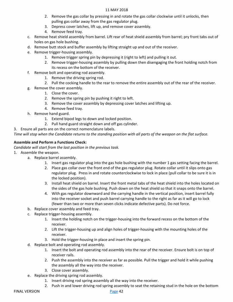
11 MAY 2018
FINAL VERSION Page 42
2. Remove the gas collar by pressing in and rotate the gas collar clockwise until it unlocks, then pulling gas collar away from the gas regulator plug.
3. Depress cover latches, lift up, and remove cover assembly. 4. Remove feed tray.
c. Remove heat shield assembly from barrel. Lift rear of heat shield assembly from barrel; pry front tabs out of holes on gas hole bushing.
d. Remove butt stock and buffer assembly by lifting straight up and out of the receiver. e. Remove trigger-housing assembly.
1. Remove trigger spring pin by depressing it (right to left) and pulling it out. 2. Remove trigger-housing assembly by pulling down then disengaging the front holding notch from
its recess on the bottom of the receiver. f. Remove bolt and operating rod assembly.
1. Remove the driving spring rod. 2. Pull the cocking handle to the rear to remove the entire assembly out of the rear of the receiver.
g. Remove the cover assembly. 1. Close the cover. 2. Remove the spring pin by pushing it right to left. 3. Remove the cover assembly by depressing cover latches and lifting up. 4. Remove feed tray.
h. Remove hand guard. 1. Extend bipod legs to down and locked position. 2. Pull hand guard straight down and off gas cylinder.
3. Ensure all parts are on the correct nomenclature labels. Time will stop when the Candidate returns to the standing position with all parts of the weapon on the flat surface.
Assemble and Perform a Functions Check: Candidate will start from the last position in the previous task. 1. Assemble the weapon.
a. Replace barrel assembly. 1. Insert gas regulator plug into the gas hole bushing with the number 1 gas setting facing the barrel. 2. Place gas collar over the front end of the gas regulator plug. Rotate collar until it slips onto gas
regulator plug. Press in and rotate counterclockwise to lock in place (pull collar to be sure it is in the locked position).
3. Install heat shield on barrel. Insert the front metal tabs of the heat shield into the holes located on the sides of the gas hole bushing. Push down on the heat shield so that it snaps onto the barrel.
4. With gas regulator downward and the carrying handle in the vertical position, insert barrel fully into the receiver socket and push barrel carrying handle to the right as far as it will go to lock (fewer than two or more than seven clicks indicate defective parts). Do not force.
b. Replace cover assembly and feed tray. c. Replace trigger-housing assembly.
1. Insert the holding notch on the trigger-housing into the forward recess on the bottom of the receiver.
2. Lift the trigger-housing up and align holes of trigger-housing with the mounting holes of the receiver.
3. Hold the trigger-housing in place and insert the spring pin. d. Replace bolt and operating rod assembly.
1. Insert the bolt and operating rod assembly into the rear of the receiver. Ensure bolt is on top of receiver rails.
2. Push the assembly into the receiver as far as possible. Pull the trigger and hold it while pushing the assembly all the way into the receiver.
3. Close cover assembly. e. Replace the driving spring rod assembly.
1. Insert driving rod spring assembly all the way into the receiver. 2. Push in and lower driving rod spring assembly to seat the retaining stud in the hole on the bottom

11 MAY 2018
FINAL VERSION Page 43
of the receiver. 3. Pull the trigger to allow the sear to drop and the group to slide all the way into the receiver.
f. Replace butt stock and buffer assembly. 1. Position the bottom recess grooves of the butt stock onto the top of the receiver recess grooves. 2. Slide the butt stock down until it locks on the receiver. Top of buffer should be flush with top of
receiver. 2. Perform a functions check
a. Ensure the safety is on FIRE (F) before moving the bolt/operating rod assembly. b. Pull and hold, with palm up, the cocking handle assembly with the right hand fully to the rear, and ensure
that the bolt locks completely to the rear. c. While holding the cocking handle to the rear (with no tension on the bolt), place the safety to SAFE (S) and
depress the trigger. Weapon should not fire. d. While holding the cocking handle to the rear (with no tension on the bolt), place the safety to FIRE (F) and
depress the trigger. Ease the bolt forward to close and lock. e. Release the trigger. f. Attempt to place the safety to SAFE (S); safety must not be able to be moved to SAFE (S).
Note: Be sure the bolt is forward with the safety on FIRE (F) when the weapon is not in use. g. Close the ejection port cover.
Time will stop when the Candidate returns to the standing position with the weapon on the flat surface.
11 MAY 2018
FINAL VERSION Page 44
Part Two-Operate an M240 Based on: 071-025-0001-Maintain an M240B Machine Gun 071-025-0003-Load an M240B Machine Gun 071-025-0005-Correct Malfunctions of an M240B/M240L Machine Gun 071-025-0004-Unload an M240B Machine Gun Task: Clear, Load, Correct Malfunctions, Unload, and Clear an M240 Machine Gun.
Condition: You are assigned an M240 machine gun and must load it in preparation for a tactical operation. While engaging targets, your weapon stops firing. You must then unload the weapon after completion of the fire mission.
Standard: Correctly perform all steps, in sequence, within 30 seconds.
Requirements: An M240 Machine Gun and blank adaptor with blank ammunition; at least three good blank rounds, followed by one expended/dummy round, and three more good rounds. Starting configuration for the weapon will be: free of ammunition, on FIRE, with the bolt forward. A target/safe direction for the Candidate to point the weapon. The weapon can alternatively be mounted on a vehicle or other type of fighting position. Hearing protection (part of the EIB uniform) must be worn when firing. As of the date of this publication, the ATN tasks are not up to date with the latest procedures and the new TM has not been published yet. The TC that replaced the FM no longer covers these procedures. These performance measures reflect the forthcoming changes to the TM as established by TACOM.
Candidate will start in the prone position not touching the weapon. 1. Clear the weapon.
a. Point weapon in a safe direction. b. Ensure the safety is on FIRE (F) before moving the bolt/operating rod assembly. c. Pull and hold, with palm up, the cocking handle assembly with the right hand fully to the rear, and ensure
that the bolt locks completely to the rear. d. While holding the cocking handle to the rear (with no tension on the bolt), place the safety to SAFE (S). e. Return the cocking handle assembly to the fully forward and locked position. f. Push in the feed cover latches, look in a safe direction, raise the feed cover, and conduct a four-point safety
check for brass, links, or ammunition. 1. Check the feed pawl assembly under the cover. 2. Check the feed tray. 3. Lift the feed tray and inspect the chamber. 4. Check the space between the face of the bolt and the chamber as well as the space under the
bolt/operating rod assembly. g. Lower the feed tray.
2. Load the weapon. a. Place link belt on feed tray with the first round against the cartridge stop with the tips of the rounds pointing
towards the barrel. Tilt the weapon to the right and/or hold the ammunition belt in place if necessary. b. Close the feed cover. c. Ensure the latches lock into place. Make sure rounds do not move away from cartridge stop during closing
and latching of cover. d. Squeeze the trigger.
3. Take immediate action to correct a malfunction. Note: Immediate action is performed to reduce a stoppage without seeking the cause. The weapon remains on your shoulder while performing immediate action procedures.
a. Pull and hold, with palm up, the cocking handle assembly with the right hand fully to the rear and ensure that the bolt locks completely to the rear.
b. Observe the ejection port to see if a cartridge case, belt link, or round ejects. c. If nothing ejects, place the safety to SAFE (S) while holding the cocking handle to the rear (with no tension
on the bolt). Return the cocking handle assembly to the fully forward and locked position and proceed to clear the weapon.
d. If a cartridge, belt link, or round ejects, push the cocking handle forward.
11 MAY 2018
FINAL VERSION Page 45
e. Squeeze the trigger and continue mission. Proceed to clear the weapon if it does not fire. 4. Unload and clear the weapon.
a. Point weapon in a safe direction. b. If the bolt is forward, ensure the safety is on FIRE (F) before moving the bolt/operating rod assembly. If the
bolt is fully locked to the rear, ensure the safety is on SAFE (S) and proceed to step f. c. Pull and hold, with palm up, the cocking handle assembly with the right hand fully to the rear, and ensure
that the bolt locks completely to the rear. d. While holding the cocking handle to the rear (with no tension on the bolt), place the safety to SAFE (S). e. Return the cocking handle assembly to the fully forward and locked position. f. Push in the feed cover latches, look in a safe direction, raise the feed cover, and conduct a four-point safety
check, removing all brass, links, or ammunition. 1. Check the feed pawl assembly under the cover. 2. Check the feed tray. 3. Lift the feed tray and inspect the chamber. 4. Check the space between the face of the bolt and the chamber as well as the space under the
bolt/operating rod assembly. g. Lower the feed tray and close the feed cover, making sure it locks shut. h. Pull and hold, with palm up, the cocking handle assembly with the right hand to the rear. i. While holding the cocking handle to the rear (with no tension on the bolt), place the safety to FIRE (F). j. While fully depressing the trigger, ease the bolt forward to close and lock. k. Release the trigger. l. Close the ejection port cover.
Note: Be sure the bolt is forward with the safety on FIRE (F) when the weapon is not in use.
11 MAY 2018
FINAL VERSION Page 46
W5: Hand Grenades Part One-Identify Hand Grenades Based on: 071-440-0031-Employ Hand Grenades during an Urban Operation Task: Identify Hand Grenades.
Condition: You are a member of a squad or team that is conducting operations in an urban environment. You have been directed to employ hand grenades against a variety of enemy targets.
Standard: Correctly identify the name and purpose of each hand grenade, using the correct nomenclature, within two minutes and 30 seconds.
Requirements: Pictures of grenades or training grenades for identification. Candidates write answers on laminated answer key labeled 1-6. 100% accuracy required for the name and nomenclature; the purpose(s) may be shorthand.
1. M67 Fragmentation. a. This grenade is used to disable or kill personnel.
2. MK3A2 Offensive Grenade. a. Use for concussion effect in enclosed areas. b. Use against enemy in bunkers, buildings and fortified areas. c. Use for blasting. d. Use for demolition tasks.
3. M84 Diversionary/Flash-Bang Stun Hand Grenades. a. Use for disorientation, confusion, and loss of hearing. b. Use as a non-lethal diversionary device. c. Use to damage eyesight and night vision during limited visibility.
4. M18 Colored Smoke. a. Use for screening. b. Use for signaling.
5. AN-M14 TH3 Incendiary Hand Grenade. a. Use to destroy equipment. b. Use to start fires.
6. ABC-M7A2 AND ABC-M7A3 riot control hand grenades. a. To control riots or disable without serious injury.

11 MAY 2018
FINAL VERSION Page 47
Part Two-Employ Hand Grenades against Troops in the Open Based on: 071-COM-4407-Employ Hand Grenades Task: Employ Hand Grenades.
Condition: You are a member of a squad or team that has been directed to employ hand grenades against troops in the open. You have two M67 Fragmentation Grenades.
Standard: Correctly perform all tasks, in sequence, within 30 seconds.
Requirements: Two training grenades with fuses. Candidate should place both grenades on their person, properly secured in their grenade pouches. If the EIB uniform does not include grenade pouches, the station should provide appropriate load bearing equipment to properly secure the grenades. Single enemy silhouette at a range of 35 meters, with a five meter radius circle around it. Covered position for the Candidate. Grader should immediately tell the Candidate if their grenade exploded within the circle, so the Candidate can prepare and throw the second grenade within the time limit if required.
1. Select proper throwing position. Note: There are five standard positions to throw grenades - standing, prone-to-standing, kneeling, prone-to-kneeling, and alternate prone. However, if you can achieve more distance and accuracy using your own personal style, do so as long as your body is facing sideways and toward the enemy’s position, and you throw the grenade overhand while maintaining control of your weapon.
a. Ensure you have a proper covered position. b. Determine the distance to the target. c. Align your body with the target.
2. Grip the hand grenade. Note: Do not remove the safety clip or the safety pin until the grenade is about to be thrown.
a. Place the hand grenade in the palm of the throwing hand with the safety lever placed between the first and second joints of the thumb. Note: For left handed throwers the grenade is inverted with the top of the fuse facing downwards.
b. Keep the pull ring away from the palm of the throwing hand so that it can be easily removed by the index or middle finger of the free hand.
3. Prepare the hand grenade. a. Tilt the grenade forward to observe the safety clip. b. Remove the safety clip by sweeping it away from the grenade with the thumb of the opposite hand. c. Insert the index or middle finger of the non-throwing hand in the pull ring until it reaches the knuckle. d. Ensure that you are holding the safety lever down firmly. e. Twist the pull ring toward the body (away from the body for left handed throwers) to release the pull ring
from the confidence clip. f. Remove the safety pin by pulling the pull ring from the grenade.
4. Throw the hand grenade so it is within the effective range of the target. a. Observe the target to estimate the distance between the throwing position and the target area.
Note: In observing the target, minimize exposure time to the enemy (no more than 3 seconds). b. Ensure there are no obstacles that can alter or block the flight of the grenade when it is thrown. c. Confirm body target alignment. d. Allow the motion of the throwing arm to continue naturally once the grenade is released. e. Seek cover to avoid being hit by fragments or direct enemy fire.
Note: If no cover is available, drop to the prone position with your protective head gear facing the direction of the grenade’s detonation.
f. Prepare second grenade. g. Reengage if grenade did not explode within five meters of the target (Grader guidance).
11 MAY 2018
FINAL VERSION Page 48
Part Three-Employ Hand Grenades through a Window, Door, or Bunker Based on: 071-COM-4407-Employ Hand Grenades 071-440-0031-Employ Hand Grenades during an Urban Operation Task: Employ Hand Grenades.
Condition: You are a member of a squad or team that has been directed to employ hand grenades against troops in a building/room/bunker 10 meters away. You have two M67 Fragmentation Grenades.
Standard: Correctly perform all tasks, in sequence, within one minute.
Requirements: Two training grenades with fuses. Candidate should place both grenades on their person, properly secured in their grenade pouches. If the EIB uniform does not include grenade pouches, the station should provide appropriate load bearing equipment to properly secure the grenades. Building with an open window/door or bunker with overhead cover. Covered position 10 meters away for the Candidate to start from. Both correct and incorrect throwing locations should be available for the Candidate to select. Grader should immediately tell the Candidate if their grenade exploded within the opening, so the Candidate can prepare and throw the second grenade within the time limit if required.
1. Identify the target to engage. 2. Select the appropriate movement technique and move to a safe, secure, and covered position with protection from
a roll back grenade and enemy fields of fire. 3. Select proper throwing position.
Note: Depending upon the type of target, type of grenade, and safety requirements for friendly forces, any of the following methods may also be used as appropriate: overarm throwing, underarm lobbing, throwing like a stone (sidearm delivery and or skipping a stone), flipping, or dropping in place, while maintaining control of your weapon.
4. Determine the distance to the target. 5. Grip the hand grenade.
Note: Do not remove the safety clip or the safety pin until the grenade is about to be thrown. a. Place the hand grenade in the palm of the throwing hand with the safety lever placed between the first and
second joints of the thumb. Note: For left handed throwers the grenade is inverted with the top of the fuse facing downwards.
b. Keep the pull ring away from the palm of the throwing hand so that it can be easily removed by the index or middle finger of the free hand.
6. Prepare the hand grenade. a. Tilt the grenade forward to observe the safety clip. b. Remove the safety clip by sweeping it away from the grenade with the thumb of the opposite hand. c. Insert the index or middle finger of the non-throwing hand in the pull ring until it reaches the knuckle. d. Ensure that you are holding the safety lever down firmly. e. Twist the pull ring toward the body (away from the body for left handed throwers) to release the pull ring
from the confidence clip. f. Remove the safety pin by pulling the pull ring from the grenade.
7. Throw the hand grenade so it is within the opening of the target. a. Observe the target to estimate the distance between the throwing position and the target area.
Note: In observing the target, minimize exposure time to the enemy (no more than 3 seconds). b. Ensure there are no obstacles that can alter or block the flight of the grenade when it is thrown. c. Confirm body target alignment. d. Allow the motion of the throwing arm to continue naturally once the grenade is released. e. Seek cover to avoid being hit by fragments or direct enemy fire.
Note: If no cover is available, drop to the prone position with your protective head gear facing the target. f. Prepare second grenade. g. Reengage if grenade did not explode within five meters of the target (Grader guidance).

11 MAY 2018
FINAL VERSION Page 49
W6: AK-47 and Foreign Weapons Based on: Department of the Army Operator’s Manual for AK-47 Assault Rifle, Produced by 203d Military Intelligence Battalion
Task: Identify foreign weapons. Clear and disassemble and AK-47. Assemble and perform a functions check on an AK-47.
Condition: You have just returned from a mission, and have been directed to perform a functions check on a recovered enemy weapon. This task will be performed on the provided poncho or material.
Standard: Identify three type of foreign weapons, their ammunition type, how they feed, and how they operate within two minutes. Clear and disassemble within one minute. Assemble, and perform a functions check within one minute. All tasks will be performed in sequence.
Station Requirements: Three types of foreign weapons (rifle, machine gun, and pistol) or detailed photographs selected by the Unit. Alcohol pens, eraser, and laminated paper numbered 1-3. Each line should have three additional lines labeled “Ammunition”, “Feed”, and “Action”. An AK-47 Assault Rifle. Starting configuration for the weapon will be: free of ammunition, loaded with an empty magazine, bolt forward, on FIRE (SEMI/AUTO). Basic maintenance tools. A target/safe direction for the Candidate to point the weapon. Material/flat surface that will prevent the Candidate from losing parts to the weapon. An area for the Candidate to place the weapons parts with the appropriate nomenclature labels. Photos of the parts with nomenclature labels should be available in the training area.
Foreign Weapons: 1. AK-47-Assault rifle.
a. Ammunition: 7.62 x 39mm. b. Feed: Magazine. c. Action: Gas-operated, rotating bolt.
2. PK-Machine Gun. a. Ammunition: 7.62 x 54mm. b. Feed: Belt. c. Action: Gas-operated, open bolt.
3. Makarov-Pistol. a. Ammunition: 9 x 18mm. b. Feed: Magazine. c. Action: Blowback.
Clear and Disassemble: Candidate will start from a standing position with the weapon resting on the flat surface. 1. Clear the weapon.
a. Place the weapon on safe. b. Remove the source of feed/magazine. c. Place the weapon on FIRE. d. Pull the operating handle to the rear and hold it. e. Inspect the chamber and receiver. f. Return the operating handle forward. g. Pull the trigger.
2. Disassemble the weapon. a. Remove the bolt cover
1. Press the serrated end of the driving spring guide into the bolt cover. 2. While holding the guide in, lift off the bolt cover, rear end first.
b. Remove the driving spring assembly 1. Push forward on the end of the driving spring guide, disengaging it from its seat in the rear of the
receiver. 2. Pull the complete driving spring assembly out of the bolt carrier.
c. Remove the bolt and carrier
11 MAY 2018
FINAL VERSION Page 50
1. Pull the operating handle fully to the rear. 2. Lift the bolt carrier slightly upward, and then remove the bolt and carrier by pulling it to the rear.
d. Remove the bolt from the carrier. 1. Press the bolt into the carrier until the bolt operating lug can be twisted free of its cam path in the
carrier. 2. Pull the bolt straight forward and out of the carrier.
e. Remove the gas cylinder tube. 1. Rotate the gas cylinder tube lock upward to free the gas cylinder tube. 2. Pull up on the rear of the hand guard and remove the tube.
Time will stop when the Candidate returns to the standing position with all parts of the weapon on the flat surface.
Assemble and Perform a Functions Check: Candidate will start from the last position in the previous task. 1. Reassemble the weapon.
a. Replace the gas cylinder tube. 1. Engage the front opening of the gas cylinder tube with the gas cylinder. 2. Seat the rear of the tube into the rear sight base. 3. Rotate the gas cylinder tube lock down to its lock position.
b. Replace the bolt. 1. Slide the spindle of the bolt into the carrier, and rotate the bolt to mate the operating lug with its
cam path. 2. Pull the bolt as far forward as possible in carrier.
c. Replace the bolt carrier 1. Slide the piston into the hole under the rear sight until carrier fits into its cuts at the rear of the
receiver. 2. Press the carrier down, with the bolt fully forward, and then slide the carrier fully forward.
d. Replace the driving spring. 1. Insert the driving spring into its hole in the rear of the carrier. 2. Reseat the guide into its slot in the receiver.
e. Replace the bolt cover. 1. Insert the front end of the bolt cover into the circular grooves in the rear sight base. 2. Apply thumb pressure over the square hole in the rear of the cover; press down and forward until
the end of the driving spring guide snaps through the hole. 2. Perform a functions check
a. Charge the weapon. b. Place the weapon on SAFE. c. Attempt to fire. Weapon should not fire. d. Place the weapon on SEMI. e. Squeeze and hold the trigger. Weapon should fire. f. Charge the weapon. g. Release trigger. Should hear disconnector. h. Squeeze trigger. Weapon should fire. i. Charge the weapon.
Note: If the weapon is equipped with an AUTO setting, proceed to steps j-o, if not, place the weapon on SAFE for the last step.
j. Place the weapon on AUTO. k. Squeeze and hold the trigger. Weapon should fire. l. Charge the weapon three times. m. Release the trigger. n. Squeeze the trigger. Weapon should not fire. o. Charge the weapon. p. Place the weapon on SAFE.
Time will stop when the Candidate returns to the standing position with the weapon on the flat surface.
11 MAY 2018
FINAL VERSION Page 51
W7: Javelin Based on: 071-060-0004-Prepare a M98-series Javelin for Firing 071-060-0006-React to Javelin that Fails to Fire
Task: Prepare a M98 Javelin for firing. Perform immediate action procedures for a misfire.
Condition: You are a gunner who has been directed to engage enemy targets with your Javelin. While engaging targets, you experience a misfire.
Standard: Prepare to fire in three minutes. Perform immediate action procedures for a misfire in two minutes. All tasks will be performed in sequence.
Station Requirements: A M98 training Javelin with appropriate tools and accessories.
Prepare to Fire: Candidate will start from a standing position next to the Javelin on the ground. 1. Prepare the CLU.
a. Ensure the power switch is in the OFF position. b. Install the CLU battery.
2. Assemble the Javelin a. Place the round on the ground with the flat sides of the end caps down and latch assembly facing up. b. Kneel on the left side of the round, at the forward end, facing forward. c. Remove the forward end cap.
1. Remove the locking pin by pulling straight up on the wire rope. 2. Turn the forward end cap latch release counterclockwise.
Note: If the forward end cap does not come off, press manual release button to relieve pressure. 3. Remove forward end cap by lifting the Javelin away from the forward end cap.
d. Remove the protective covers from the CLU interface connectors. Candidate may verbalize if not equipped. e. Remove the protective covers from the round interface connectors. Candidate may verbalize if not
equipped. f. Position protective covers so that no interference will exist when placing the round interface bracket in
round hooks. g. Engage CLU and round interface connectors by sliding forward, then press down on CLU.
Note: Round and CLU are connected correctly when latch release snaps into place. h. Ensure that the round and CLU are connected.
1. Rock the CLU from side-to-side. 2. Pick up the Javelin.
i. Position open end of round on forward end cap. 3. Power up the CLU.
a. Open day sight and NVS lens covers on CLU. b. Set power switch to the NIGHT position.
Note: The CLU has four modes of operation: Off, Day, Night (IR Surveillance) and test. c. Verify the CLU indicators are lit.
Note: CLU indicators may flash on and off during initial power up. This indicates that the battery needs time to warm up before CLU can power up properly.
d. Perform battery warm-up procedures, as required. 1. Turn the power switch to the DAY position for 30 to 60 seconds. Grader will state, “30 seconds
has elapsed”. 2. Turn the power switch to the OFF position, then back to the NIGHT position.
e. Repeat warm-up if indicators continue to flash. f. Adjust diopter adjust ring for best clarity of CLU display.
Note: The Javelin is now prepared to engage a target. g. Attempt to fire Javelin.
1. Acquire the target.
11 MAY 2018
FINAL VERSION Page 52
2. Lock-on the target. h. Squeeze the fire trigger. Grader will state “misfire”.
Perform Immediate Action for a misfire: Candidate will start from the last position in the previous task. 1. Attempt to engage the target again.
a. Release the seeker and fire triggers. b. Acquire the target. c. Lock-on the target. d. Squeeze the fire trigger. Grader will state, “You have a second misfire”.
2. React to second misfire. a. Disconnect and reconnect CLU from the round.
1. Turn OFF the CLU. 2. Set the Javelin on ground, pointed in direction of enemy target, with the CLU handgrips facing up. 3. Keep back blast area clear. 4. Press the latch release and disconnect the CLU from the round. 5. Check for dirt and debris. 6. Reconnect the CLU to the same round. 7. Turn ON the CLU. 8. Verify CLU indicators are lit. 9. Adjust diopter ring.
b. Attempt to reengage the target. 1. Acquire the target. 2. Lock-on the target. 3. Squeeze the fire trigger. Grader will state, “You have a third misfire”.
3. Replace the round. a. Turn OFF CLU. b. Place the Javelin on the ground, pointing toward the enemy. c. Disconnect the CLU from the round. d. Move 25 meters away or move the round 25 meters from the firing position. Candidate verbalizes this step. e. Stay clear of the forward and aft ends of the round at all times. f. Obtain a replacement round. Candidate verbalizes this step. g. Notify supervisor. Candidate verbalizes this step.
11 MAY 2018
FINAL VERSION Page 53
W8: M2 .50 Caliber Machine Gun Based on: 071-022-0001-Maintain a Caliber .50 M2 Series Machine Gun 071-022-0003-Load a Caliber .50 M2 Series Machine Gun 071-022-0005-Correct Malfunctions of a Caliber .50 M2 Series Machine Gun 071-022-0004-Unload a Caliber .50 M2 Series Machine Gun
Task: Clear, load, fire until a stoppage occurs, perform immediate action, expend remaining ammunition, unload and clear an M2 Machine Gun.
Condition: You are a gunner who has been directed to engage enemy targets with your machine gun. While engaging targets, you experience a misfire.
Standard: Correctly perform all steps, in sequence, in one minute or less.
Station Requirements: An assembled M2 Caliber .50 machine gun, with headspace and timing set, set up for firing blanks. Starting configuration for the weapon will be: free of ammunition, on FIRE/full auto, with the bolt forward. Weapon may be mounted on a tripod, vehicle, or other fighting position, but must be well emplaced and secure. A five round (minimum) belt of blank ammunition, with one dummy round in the middle. Safe direction for the Candidate to engage. Hearing protection (part of the EIB uniform) must be worn when firing.
Candidate will start in the seated (if on tripod) or standing (if vehicle-mounted) position not touching the weapon. 1. Clear the weapon.
a. Place the trigger block on SAFE. b. Unlock the bolt latch release. c. Raise the cover. d. Lift the cartridge extractor. e. Remove the ammunition belt from the freed way. f. Place cartridge extractor down. g. Close the cover. h. Pull and lock the bolt to the rear, leaving the retracting slide handle to the rear. i. Open the cover. j. Inspect the chamber and T-slot for rounds. k. Press the bolt latch release and ease the bolt forward with retracting slide handle. l. Close the cover.
2. Load the weapon. a. With cover closed.
1. Ensure the bolt is forward, and bolt latch release is locked. 2. Ensure the correct front cartridge stop is installed. 3. Insert the double-loop end of the ammunition belt into the feed way until the first round is
engaged by the belt-holding pawl. 4. Pull the retracting slide handle rearward, retracting the bolt all the way to the rear. 5. Release handle.
Note: The machine gun is now half-loaded. A round is not in the chamber. 6. Pull the retracting handle to the rear for a second time to fully load the gun. 7. Release handle.
Note: A round is now in the chamber and the machine gun is ready to fire. 3. Take immediate action to correct a malfunction.
a. Place the trigger block on FIRE. b. Attempt to fire the weapon until a stoppage occurs. c. Immediate action for a cool weapon (has fired less than 200 rounds in two minutes)
1. Hold the weapon on target. 2. Wait 10 seconds in case the weapon has a hang fire. Candidate verbalizes this step. 3. Pull the retracting handle to the rear. 4. Observe that the round or fired case is ejected.
11 MAY 2018
FINAL VERSION Page 54
a. If it ejects, continue to next step. b. If it does not eject, proceed to unload the weapon.
5. Return the retracting slide handle to its forward position. 6. If the bolt locks to the rear, depress the bolt latch to return the bolt to the forward position. 7. Attempt to reengage the target; expend remaining ammunition.
4. Unload and clear the weapon. a. Remove all ammunition and links from the machine gun.
1. Place trigger block on SAFE. 2. Unlock the bolt latch release. 3. Raise the cover. 4. Lift the cartridge extractor. 5. Remove the ammunition belt from the feed way. 6. Place cartridge extractor down. 7. Close the cover. 8. Pull and lock the bolt to the rear, leaving the retracting slide handle to the rear. 9. Open the cover. 10. Inspect the chamber and T-slot for rounds. 11. Press the bolt latch release and ease the bolt forward with retracting slide handle. 12. Close the cover.
11 MAY 2018
FINAL VERSION Page 55
W9: Heavy Grenade Launcher Based on: 071-030-0001-Maintain an MK19 Grenade Machine Gun 071-030-0005-Load an MK 19 Grenade Machine Gun 071-030-0008-Correct Malfunctions of an MK19 Grenade Machine Gun 071-030-0006-Unload an MK 19 Grenade Machine Gun 331-18B-2421-Engage Targets with the MK47 Advanced Lightweight Grenade Launcher
Task: Clear, load, fire until a stoppage occurs, perform immediate action, expend remaining ammunition, unload and clear a MK 19 Machine Gun.
Condition: You are a gunner who has been directed to engage enemy targets with your machine gun. While engaging targets, you experience a misfire.
Standard: Correctly perform all steps, in sequence, in one minute or less.
Station Requirements: An assembled MK 19 grenade machine gun, prepared for firing. Starting configuration for the weapon will be: free of ammunition, on FIRE, with the bolt forward. Weapon may be mounted on a tripod, vehicle, or other fighting position, but must be well emplaced and secure. A five round (minimum) belt of dummy ammunition. Target for the Candidate to engage. A MK 47 Grenade Launcher or other variant may be used based on the Unit’s inventory; use the standards outlined in that weapon’s TM for Clear, Load, Perform Immediate Action, Unload, and Clear.
Candidate will start in the seated (if on tripod) or standing (if vehicle-mounted) position not touching the weapon. 1. Clear the weapon.
a. Clear the bolt. 1. Place the safety switch to SAFE. 2. Remove the case catch bag, if applicable. 3. Charge the weapon.
a. Lower both charger handles. b. Pull both charger handles to the rear ensuring the bolt locks to the rear. c. Return both charger handles to the forward position. d. Rotate only one charger handle up.
4. Remove live round or cartridge case from the bolt, if present. a. Insert the tip of a cleaning rod through the receiver rail as close to the bolt face as possible. b. Place the tip of the cleaning rod on top of the live round or cartridge case, as close to the
bolt face as possible. c. Position one hand beneath the weapon, attempting to catch the round as it falls out. d. Force the live round off the bolt face and out the bottom of the gun by pushing down on the
cleaning rod. e. Attempt to catch the live round as it falls out.
b. Clear the feeder. 1. Open the top cover assembly. 2. Remove linked rounds, if present.
a. Reach beneath the feed tray with one hand. b. Press and hold both the primary and secondary positioning pawls. c. Slide the linked rounds out of the feeder and out the feed throat.
c. Return the bolt to the forward position. 1. Place the safety switch on FIRE. 2. Hold one charger handle to the rear. 3. Ride the bolt forward by squeezing the trigger and easing the bolt forward. 4. Ensure both charger handles are forward and in the up position. 5. Place the safety switch on SAFE.
2. Load the weapon. a. Attach feed throat to feeder.

11 MAY 2018
FINAL VERSION Page 56
1. Squeeze the spring-loaded pins on feed throat. 2. Insert into the slots on both sides of the feeder.
b. Insert a round. Note: When using a vehicle mount, attach ammunition can bracket and can. When using a ground tripod mount, feed the ammunition directly from the can.
1. Open the top cover assembly. 2. Insert the round through the feed throat (female first) into the feeder. 3. Push the round across the first set of feeder pawls. 4. Ensure the round is straight and firmly seated against the bolt. 5. Push the secondary drive lever to the right.
Note: This moves the feed slide to the left. 6. Close the top cover assembly.
c. Load the first round to the fully-loaded position. 1. Charge the weapon.
a. Lower both charger handles. b. Pull both charger handles to the rear ensuring the bolt locks to the rear. c. Return both charger handles to the forward position.
2. Place safety switch in FIRE position. 3. Squeeze the trigger allowing the bolt to slam forward. 4. Rotate both charger handles down. 5. Pull both charging handles to the rear.
Note: This moves the round down the curved rail on the vertical cam assembly. It forces the round down the bolt face out of the extractors into the bolt fingers (position for firing - full load).
6. Return both charging handle to the forward and up position. 3. Take immediate action to correct a malfunction.
a. Attempt to fire the weapon until a stoppage occurs. b. Take immediate action.
1. Hold weapon on target. 2. Pull the bolt to the rear. 3. Attempt to catch live round as it ejects. 4. Push the charger handles forward to the up position. 5. Place the weapon on SAFE. 6. Check for bore obstruction.
a. If bore is clear, go to next step. b. If a bore obstruction is present, proceed to unload the weapon.
7. Place the weapon on FIRE. 8. Attempt to reengage the target; expend remaining ammunition.
4. Unload and clear the weapon. a. Place the safety switch to SAFE. b. Remove the case catch bag, if applicable. c. Charge the weapon.
1. Lower both charger handles. 2. Pull both charger handles to the rear ensuring the bolt locks to the rear. 3. Return both charger handles to the forward position. 4. Rotate only one charger handle up.
d. Remove live round or spent case from the bolt, if present. 1. Insert the tip of a cleaning rod through the receiver rail as close to the bolt face as possible. 2. Place the tip of the cleaning rod on top of the live round or spent case, as close to the bolt face as
possible. 3. Position one hand beneath the weapon to catch the round as it falls out. 4. Force the live round off the bolt face and out the bottom of the gun by pushing down on the
cleaning rod. 5. Attempt to catch the live round as it falls out.

11 MAY 2018
FINAL VERSION Page 57
e. Open the top cover assembly. f. Remove linked rounds from the feeder, if present.
1. Reach beneath the feed tray with one hand. 2. Press and hold both the primary and secondary positioning pawls. 3. Slide the linked rounds out of the feeder and out the feed throat.
g. Return the bolt to the forward position. 1. Place the weapon on FIRE. 2. Hold one charger handle to the rear. 3. Ride the bolt forward by squeezing the trigger and easing the bolt forward. 4. Ensure both charging handles are forward and up position. 5. Place the weapon on SAFE.

11 MAY 2018
FINAL VERSION Page 58
W10: Anti-Tank Weapons Based on: 071-054-0001-Prepare an M136 Launcher for Firing 071-054-0003-Perform Misfire Procedures on an M136 Launcher 071-318-2204-Prepare an M72 Series Light Anti-Tank Weapon for Firing 331-18B-2103-Engage Targets with the Carl Gustaf 84-mm Recoilless Rifle 071-318-2255-Perform Misfire Procedures on an 84-MM Recoilless M3 Rifle
Task: Prepare an M136 launcher/M72 launcher/84-mm Carl Gustav Recoilless Rifle for firing. Perform immediate action procedures for a misfire (and unload for the Carl Gustaf).
Condition: You are a member of a squad or team who has been directed to engage enemy targets with your AT4/LAW/Carl Gustaf. While engaging targets, you experience a misfire.
Standard: Prepare and fire in 15 seconds (one minute for the Carl Gustaf). Perform misfire procedures in 45 seconds (perform misfire procedure and unload in one minute for the Carl Gustaf). All tasks will be performed in sequence.
Station Requirements: An M136 training launcher/M72 training launcher/Carl Gustaf with appropriate tools and accessories, in the appropriate starting configuration. Use the appropriate set of standards based on the weapon system being used:
M136 AT4 Prepare and Fire: Candidate will start from a standing position with the weapon slung. 1. Prepare launcher for firing.
a. Remove the AT4 from its carrying position, and cradle in the left arm. b. Keeping the munition's muzzle toward the target area. c. Pull and release the transport safety pin using the right hand. d. Unsnap, unfold and hold the shoulder stop with the right hand. e. Grip base of the sling on the front of the launcher with the left hand and shoulder stop with the right. f. Raise the munition out away from the body. g. While keeping the munition pointed at the target, pivot the body 90 degrees to face the target. h. Place the munition on the right shoulder. i. Grasp the front sight cover with the right hand, pressing down, and sliding it rearward. j. Grasp the rear sight cover with the right hand, pressing downward and sliding it forward. k. Ensure the back blast area is clear. Candidate visually checks and states, “Back blast area clear”.
2. Arm the AT4. a. Unfold the cocking lever with the right hand. b. Place the thumb under the cocking lever.
1. Push the cocking lever forward using the support of the fingers in front of the firing mechanism. 2. Rotate the cocking lever downward and to the right. 3. Allow the cocking lever to slide backward.
c. Adjust the rear sight to the range given in the instructions. d. Place the first two fingers of the right hand on the red safety catch and extend the thumb. e. Pull back on the sling with the left hand to seat the shoulder stop firmly against the shoulder. f. Attempt to fire the munition.
Perform misfires procedures: Candidate will start from the last position in the previous task. 1. Announce “Misfire” just loud enough for friendly personnel in the immediate area to hear. 2. Maintain the original sight picture. 3. Keep the AT4 pointed at the target. 4. Keep the back blast area clear. Candidate visually checks and states, “Back blast area clear”. 5. Release the red trigger button. 6. Release the red safety release catch. 7. Wait five seconds. Candidate verbalizes this step.

11 MAY 2018
FINAL VERSION Page 59
8. Remove your right hand from the firing mechanism. 9. Check the back blast area. 10. Recock the AT4. 11. Firmly press downward on the red safety release catch, and hold. 12. Aim the AT4 at target. 13. Press and hold the red trigger button. Grader will state, “Misfire”. 14. Announce “Misfire” just loud enough for friendly personnel in the immediate area to hear. 15. Keep the AT4 pointed at the target. 16. Release the red trigger button. 17. Release the red safety release catch. 18. If situation permits, wait two minutes. Candidate verbalizes this step. 19. Return the cocking lever to the SAFE position. 20. Remove the AT4 from your shoulder, keeping it pointed in safe direction. 21. Cradle the AT4 in your left arm. 22. Reinsert the transport safety pin / fork. 23. Break off the sights to identify the AT4 as misfired. Candidate verbalizes this step. 24. Place the AT4 on the ground, pointed in safe direction. 25. Notify supervisor. Candidate verbalizes this step.
M72 LAW Prepare and Fire: Candidate will start from a standing position with the weapon slung. 1. Prepare the LAW for firing.
Note: The M72-series munitions can be fired from your left or right shoulder. a. Cradle the launcher in your non-firing arm. b. Remove transport pin. c. Rotate the rear cover downward.
Note: Sling will fall off. Save sling for reuse if launcher is not fired. d. Grasp the rear sight cover with your firing hand. e. Grasp the launcher, forward of the barrel detent, with your non-firing hand. f. Pull your hands sharply in opposite directions to extend the launcher. g. Check tube lock by trying to push tubes together. h. Grip underneath the rear end of the launcher with your firing hand and underneath the forward end of the
launcher with your non-firing hand. i. Raise the launcher out and away from your body. j. While keeping the launcher pointed at the target, pivot your body 180 degrees to face the target. k. Place the launcher on your firing side shoulder.
2. Arm the LAW. a. Ensure the back blast area is clear of personnel. b. Pull the trigger arming handle to the ARM position.
Note: If the trigger arming handle will not remain in the ARM position, the launcher is not fully extended. c. Pull the rear cover/shoulder stop firmly against your shoulder, and hold. d. Attempt to fire. Grader will state, “Misfire”.
Perform Misfire Procedures: Candidate will start from the last position in the previous task. 1. Squeeze the trigger spring boot again. 2. Announce “MISFIRE”. 3. Wait ten seconds (Candidate verbalizes this step.), and place the trigger safety handle on SAFE. 4. Remove the munition from your shoulder. 5. Wait one minute. Candidate verbalizes this step. 6. Partly collapse the launcher (about four inches), and then extend it to the locked position. 7. Push in on the launcher to ensure it is fully locked. 8. Place the launcher on your shoulder; check back blast area; arm, aim, and fire the munition.

11 MAY 2018
FINAL VERSION Page 60
9. If the launcher fails to fire, firmly squeeze the trigger spring boot again. 10. If the munition still does not fire, announce “MISFIRE”. 11. Release the trigger. 12. Maintain firing position for ten seconds (Candidate verbalizes this step.) and place the trigger safety handle on SAFE. 13. Wait one minute. Candidate verbalizes this step. 14. Remove the munition from your shoulder, keeping the munition pointed toward the target.
Note: DO NOT collapse the launcher. 15. Carefully lay the munition on the ground. 16. Notify leadership, follow post regulations and unit SOPs. Candidate verbalizes this step. Carl Gustaf 84-mm Recoilless Rifle Prepare and Fire: Candidate will start from a standing position with the weapon slung or on a flat surface. 1. Load the weapon.
a. Gunner/Candidate. 1. Assume the firing position. 2. Push the cocking handle forward with the right thumb, returning the right hand to the firing grip
with the index finger running along the trigger guard. 3. Put the safety catch on "S" with the left hand and return the left hand to the front grip. 4. Give the order, "Load," to the assistant gunner.
b. Assistant Gunner/Grader. 1. Repeat, "Load." 2. Open the breech by pushing the venturi lock knob forward with the right hand and rotating the
venturi with the left hand on the venturi lever. 3. Examine the breech and barrel for dirt or unburnt propellant. 4. Pick up the round, nose forward, with the right hand, using the underhand grip; remove the
rubber protective cover and grasp the rim of the round with the left hand, placing a finger in the recess in the rim of the round.
5. Insert the round into the chamber, ensuring that the recess is in line with the cartridge guide. 6. Close the breech with the left hand. 7. Tap the venturi lock knob to the rear to ensure that the lock is closed. 8. Check the back blast area and report, "Back blast area clear."
Note: Ensure the back blast area is clear of all personnel and loose debris. 2. Acquire the target.
a. 78 MK1 telescope. 1. Estimate the range to the target. 2. Set the range on the range knob. 3. Position eye to the rear of the telescope. 4. Move head forward or backward until a full view of the target is obtained. 5. Place the pointer or appropriate lead mark on the center of the visible mass of the target.
b. Open sight. 1. Fold the front and rear sights out from their position against the barrel. 2. Set the estimated range using the correct temperature mark. 3. Take a normal sight picture.
Note: Consider strong winds when firing, particularly at longer ranges; there is no specific amount of "aim off" given; but, as a guide, in a strong wind at a range of about 300 meters, aim at the rear edge or upwind side of the turret as opposed to the center of the visible mass.
3. Fire the weapon. a. Gunner/Candidate.
1. Identify the target. 2. Place the safety catch on "F." 3. Aim and apply slight pressure on the trigger. 4. When satisfied with the aim, fire the weapon. Grader will state, “Misfire”.

11 MAY 2018
FINAL VERSION Page 61
Perform Misfire Procedure and Unload: Candidate will start from the last position in the previous task. 1. Misfire procedures.
a. Keep aim on target. b. Announce, "Misfire." c. Wait five seconds. Candidate verbalizes this step. d. Reengage target (1st attempt).
1. Recharge firing mechanism. 2. Aim on the target. 3. Announce, "On the way." 4. Pull the trigger. Grader will state, “Misfire”. 5. Keep aim on target. 6. Announce, "Misfire." 7. Recharge firing mechanism. 8. Direct Assistant Gunner/Grader to check the venturi lock.
e. Reengage target (2nd attempt) once Assistant Gunner/Grader announces, "Venturi lock checked." 1. Aim on the target. 2. Announce, "On the way." 3. Pull the trigger. Grader will state, “Misfire”. 4. Keep aim on target. 5. Announce, "Misfire." 6. Rotate the safety catch to S (safe). 7. Recharge firing mechanism. 8. Maintain firing position and wait two minutes. Candidate verbalizes this step. 9. Direct Assistant Gunner/Grader to load a new round.
Note: Assistant gunner will inspect the misfired round. If the percussion cap on misfired round was impacted by firing pin the misfired round is to be treated as a dud and handled in accordance with range or unit standard operating procedures. If the percussion cap was not impacted the firing pin and firing mechanism should be checked.
f. Reengage target (3rd attempt). 1. Aim on the target. 2. Announce, "On the way." 3. Pull the trigger. 4. Keep aim on target. Grader will state, “Misfire”. 5. Announce, "Misfire."
2. Unload the weapon. a. Gunner/Candidate.
1. Place the safety catch on "S" with the left hand. 2. Return the left hand to the front grip. 3. With the trigger hand on the firing grip, place the right index finger along the trigger guard. 4. Announce, "Unload." 5. After receiving "Clear" from the assistant gunner, place the safety catch on "F," press the trigger,
and remove the telescope. b. Assistant Gunner/Grader.
1. Repeat, "Unload." 2. Open the breech and tap the venturi lock knob forward to partially eject the round/empty casing. 3. Grasp the rim of the round or empty casing with the left hand, and remove it from the chamber. If
it is a casing, cast it aside out of the back blast area. If it is a live round, catch it with an underhand grip of the right hand.
4. Close the breech with the left hand. 5. Tap the venturi lock knob to the rear. 6. Report, "Clear."
Time will stop when the Candidate says, “Unload” (step 2a4).

11 MAY 2018
FINAL VERSION Page 62
Chapter 11-Medical Lane
M1: Request Medical Evacuation Based on: 081-COM-0101-Request Medical Evacuation
Task: Request a Medical Evacuation (MEDEVAC).
Condition: You are a member of a team who has been directed to request a MEDEVAC for a wounded teammate. You are in a wartime, non-CBRNE environment. Give the Candidate the security of the pickup site, and any additional situation guidance.
Standard: Prepare to send the MEDEVAC within three minutes. Transmit lines 1-5 within 25 seconds of initial contact with evacuation unit. Transmit lines 6-9 within one additional minute. All tasks will be performed in sequence, using the proper brevity codes and radiotelephone pronunciation and procedures, with 100% accuracy.
Station Requirements: A protractor and military map with Candidate location clearly plotted. One set of Signal Operating Instructions (SOI) according to unit SOP, with all pertinent frequencies listed. All call signs and suffixes required. Two operational radios, powered on, with both the MEDEVAC and operational frequencies programmed. It will be set to the operational frequency so the Candidate is forced to make the changes based on the SOI. Two Department of Defense (DD) Form 1380 Tactical Combat Casualty Care (TCCC) Cards properly filled out for the simulated casualties; the casualties should be of different type and precedence. The Candidate is required to derive the applicable information from the cards, not have the information given to them. At least three appropriate signaling devices, such as VS-17 panel, colored smoke grenades, strobe lights, etc., to be used as the method of marking the pickup site. The Candidate must select a device to use, not have the information given to them. Candidate must derive the appropriate special equipment based on the test site, casualties, and additional situation guidance from the Grader. Laminated paper with nine blank lines, alcohol pens and eraser. While all the information will be available in the holding area, during testing the Candidate must not be given any Graphic Training Aids (GTAs), cheat sheets, brevity codes, etc. At the test site, the Candidate must not be able to see any of the information/equipment until time has started. The scenarios/grids/frequencies/casualties must differ between the training week, test holding area, and at least two test sites.
Prepare the MEDEVAC request: 1. Determine the grid coordinates for the pickup site.
a. Candidate uses map and protractor, and provides a complete six digit grid with identifier, accurate within 200 meters.
2. Determine operational radio frequency, call sign, and suffix. a. Candidate uses SOI to determine the necessary information. b. Candidate makes the appropriate changes to the radio, and prepares it for transmission on the MEDEVAC
frequency. 3. Determine number of patients and their precedence.
a. Candidate uses TCCC Cards to determine the necessary information. 4. Determine special equipment required.
a. Candidate determines this information based on the site location, patient injuries, and additional Grader guidance during the introductory brief.
5. Determine number and type of patients. a. Candidate uses TCCC Cards to determine the necessary information.
6. Determine security of pickup site. a. Give this information to the Candidate during the Condition brief.
7. Determine method of marking the pickup site. a. Candidate must choose based on the choices given.
8. Determine patient nationality and status. a. Candidate uses TCCC Cards to determine the necessary information. b. The number of patients in each category need not be transmitted.
9. Determine terrain description.

11 MAY 2018
FINAL VERSION Page 63
a. This is used when not in a CBRNE environment. b. Candidate determines this information based on the site location, map, and additional Grader guidance
during the Condition brief. c. While only required in a peacetime environment, this information can be given as it will be transmitted later
on an encrypted frequency.
Transmit lines 1-5: 1. Candidate states, “I have a MEDEVAC request”. Grader provides a response within three seconds. 2. Line 1: Six digit grid, including grid zone identifier. 3. Line 2: Operational frequency, call sign, and suffix.
a. Candidate will use this frequency later to transmit lines 6-9. 4. Line 3: A-Urgent, B-Urgent-Surgical, C-Priority, D-Routine, E-Convenience.
a. Candidate uses brevity codes. b. Candidate states, “Break” between each category.
5. Line 4: A-None, B-Hoist, C-Extrication Equipment, D-Ventilator. a. Candidate uses brevity codes.
6. Line 5: L+#-Number of litter patients, A+#-Number of ambulatory patients. a. Candidate uses brevity codes. b. Candidate states, “Break” between each category.
7. End transmission by stating, “Over”.
Transmit lines 6-9: 1. Candidate switches radio to operational frequency, and regains contact with evacuation platform for transmission of
remaining lines. Grader initiates contact and requests remaining lines as soon as Candidate switches the radio frequency.
2. Line 6: N-No enemy troops in the area, P-Possibly enemy troops in the area, E-Enemy troops in the area, X-Enemy troops in the area (armed escort required).
a. Candidate uses brevity codes. 3. Line 7: A-Panels, B-Pyrotechnic signal, C-Smoke, D-None, E-Other.
a. Candidate uses brevity codes. 4. Line 8: A-U.S. military, B-U.S. citizen, C-Non-U.S. military, D-Non-U.S. citizen, E-Enemy prisoner of war.
a. Candidate uses brevity codes. 5. Line 9: Provide description of pertinent terrain information. 6. End transmission by stating, “Over”, and wait for any additional guidance or clarification.
11 MAY 2018
FINAL VERSION Page 64
M2: Provide Care under Fire and Move a Casualty. Based on: 081-COM-1001-Evaluate a Casualty 081-000-0048-Apply a Combat Application Tourniquet 081-COM-1046-Movement of a Casualty 081-000-0013-Initiate a Tactical Combat Casualty Care Card
Task: Perform care under fire. Transport and transfer a casualty.
Condition: You are a member of a team or squad on a combat patrol that has come under sporadic small arms fire. You witness a teammate in the open receive a gunshot wound to the (Grader will state left or right) leg. Your teammate is struggling to reach his/her CAT, and you see bright red arterial bleeding. No spinal injury is suspected and you are not in a CBRNE environment.
Standard: Perform Care under Fire, in sequence, within two minutes. Transport and Transfer, in sequence, within 15 minutes. You must not cause further injury, have no safety violations, and not lose any equipment.
Station Requirements: A simulated casualty; either an actual soldier or mannequin (with all extremities) weighing 160-200 lbs. The casualty must have a clearly visible simulated extremity wound, and be in a full combat uniform per Unit SOP, including weapon, and a fully packed Improved First Aid Kit (IFAK) and CAT. The casualty’s TCCC Card will have the administrative data already filled out. Casualty should be positioned on the ground, 10 meters away from a covered position, where the Candidate will apply aid. An additional covered position 50 meters away where the Candidate will fill out the TCCC Card. A functional Sked litter, packaged per Unit SOP. Candidate will start the task in full EIB uniform, carrying the Sked litter, with a magazine of blank rounds loaded. Grader may provide verbal cues as to the enemy rate of fire, use a pneumatic gun, or have Opposing Force (OPFOR) soldiers returning fire with blanks. Provide the Candidate with, or ensure the Candidate has a watch with the correct date and time. Candidate will start from an open position 10 meters away from the first covered position. Hearing protection (part of the EIB uniform) must be worn when firing.
Care under Fire: 1. Return fire and take cover until fire suppression is achieved.
a. Candidate will return fire. b. Direct the casualty to return fire, move to cover, and administer self-aid to stop the bleeding. c. When the Candidate has demonstrated the proper techniques, the Grader will state “Fire superiority has
been achieved”, or the enemy fire will stop. 2. Move the casualty, his/her weapon, and mission-essential equipment to cover using the Cradle-drop drag (below),
or any appropriate technique, without causing further injuries or losing any equipment. a. With the casualty lying on his/her back, kneel at the head. b. Slide your hands, palms up, under the casualty's shoulders getting a firm hold under his/her armpits. c. Partially rise, supporting the casualty's head on one of your forearms.
Note: You may bring your elbows together and let the casualty’s head rest on both of your forearms. d. With the casualty in a semi-sitting position, rise and drag the casualty backwards to the nearest covered
position. 3. Administer life-saving bleeding control by applying the CAT to the wounded extremity.
a. Expose the wound. b. Remove the CAT from the casualty’s IFAK. c. Place CAT, 2-3 inches above the wound on the injured extremity. d. Pull the free end of the self-adhering band through the buckle and route through the friction adapter buckle. e. Pull the self-adhering band tight around the extremity and fasten it back on itself as tightly as possible. f. Twist the windlass until the bleeding stops.
Note: Candidate will verbalize this, and will ensure to not overtighten if using an actual soldier as a casualty. g. Lock the windlass in place within the windlass clip. h. Secure the windlass with the windlass strap. i. Assess for absence of a distal pulse.
Note: Candidate should perform and verbalize with proper technique. Pulse must be taken with skin to skin contact, and not using their thumb.

11 MAY 2018
FINAL VERSION Page 65
j. Place a "T" and the time of the application on the casualty with a marker (provided in casualty’s IFAK). Note: This can be simulated and verbalized, or a piece of lamination can be applied to the casualty’s forehead so each Candidate can perform the task.
k. Secure the CAT in place with tape (provided in casualty’s IFAK).
Transport and Transfer a Casualty: 1. Move the casualty using a Sked litter.
a. Prepare the Sked litter for transport. 1. Remove the Sked litter from its pack and place it on the ground, unfasten the retainer strap. 2. Step on the foot end of the Sked litter and unroll the Sked completely, bending the Sked in half
and back roll. 3. Repeat with the opposite end of the litter so that the Sked litter lays flat. 4. Pull out the handholds, straps for the casualty, and dragline at the head of the litter.
b. Place and secure a casualty to a Sked litter. 1. Place the Sked litter next to the casualty so that the head end of the litter is next to the casualty's
head and place the cross straps under the Sked litter. 2. Log roll the casualty onto his/her side in a steady and even manner.
Note: Casualty must be rolled onto the non-tourniquet leg. 3. Slide the Sked litter as far under the casualty as possible. 4. Gently roll the casualty until he/she is again lying on his/her back with the litter beneath him/her. 5. Slide the casualty to the middle of the Sked litter, keeping his/her spinal column as straight as
possible. 6. Pull out the straps from under the Sked litter and bring the straps across the casualty. 7. Lift the sides of the Sked litter and fasten the four cross straps to the buckles directly opposite the
straps. 8. Lift the foot portion of the Sked litter feeding the foot straps over the casualty's lower extremities
and through the unused grommets at the foot end of the Sked litter. 9. Fasten the straps to the buckles. 10. Check to make sure the casualty is secured to the Sked litter.
c. Suppress the enemy. 1. Candidate will return fire. 2. When the Candidate has demonstrated the proper techniques, the Grader will state “Fire
superiority has been achieved”, or the enemy fire will stop. d. Drag the casualty 50 meters to the casualty collection point (CCP).
2. Document the injuries and the treatment given on the casualty's own TCCC Card (found in casualty's IFAK) for transfer to medical personnel.
a. Remove TCCC Card. Administrative data will already be filled out. b. Complete all pertinent entries as fully as possible.
1. Front of card. a. Evacuation (EVAC) - Mark an “X” on the casualty’s evacuation priority/precedence (Urgent;
Priority; or Routine). b. Date - Write date of injury in DD-MMM-YY format. For example, “29-JUN-13”. c. Time - Write 24 hour time of injury, and indicate whether local (L) or Zulu (Z) time. For
example, “1300Z”. d. Mechanism of Injury - Mark an “X” on the mechanism or cause of injury (artillery, blunt,
burn, fall, grenade, gunshot wound (GSW), improvised explosive device (IED), landmine, motor vehicle crash/collision (MVC), rocket propelled grenade (RPG), other (specify)). Mark all that apply.
e. Injury - Mark an “X” at the site of the injury(ies) on the body picture. f. TQ: R Leg (tourniquet, right leg) - If a tourniquet is applied to the right leg, write type of
tourniquet used and the time of tourniquet application. g. TQ: L Leg (tourniquet, left leg) - If a tourniquet is applied to the left leg, write type of
tourniquet used and the time of tourniquet application.

11 MAY 2018
FINAL VERSION Page 66
2. Back of card. a. Evacuation (EVAC) - Mark an “X” on the casualty’s evacuation priority/precedence (Urgent;
Priority; or Routine). b. C - Mark an “X” for all Circulation hemorrhage control interventions. For tourniquets (TQ),
mark category (Extremity, Junctional and/or Truncal) and write name of TQ(s) used. c. First Responder Name - Print the first responder’s name (Last, First). d. First Responder Last 4 - Write last four numbers of first responder’s Social Security number.
c. Attach the completed TCCC Card to the casualty; in a visible area where follow on medical staff will see it. Note: Do not attach the TCCC Card to the casualty's body armor as this equipment may will be separated from the casualty once they arrive at the medical treatment facility (MTF).

11 MAY 2018
FINAL VERSION Page 67
M3: Perform First Aid to Restore Breathing and/or Pulse. Based on: 081-831-1023-Perform First Aid to Restore Breathing and/or Pulse 081-833-0142-Insert a Nasopharyngeal Airway
Task: Perform first aid to restore breathing and/or pulse of an unconscious adult.
Condition: You see an adult who appears to be choking collapse to the ground. You are not in a combat situation or CBRNE environment and no spinal injury is suspected. You have a Basic Life Support (BLS) bag.
Standard: Correctly perform all tasks to standard, in sequence, within seven minutes, without causing further injury.
Station Requirements: Cardiopulmonary Resuscitation (CPR) mannequin is preferred so the Grader can adequately judge the depth and rate of compressions, as well as the quality of breaths given. If a non-CPR mannequin is used, it should be fully functional with all extremities for maximum training value. The mannequin and Candidate will start in the standard field uniform. A BLS bag with at least two different sizes of Nasopharyngeal Airways (NPAs), and CPR accessories, such as face shields. The mannequin will be on a hard, flat surface.
1. Approach the casualty and check for responsiveness. Grader will state, “Casualty is unresponsive”. a. Direct a specific bystander to call for medical personnel. b. Direct another specific bystander to retrieve an Automated External Defibrillator (AED).
2. Roll the casualty onto his/her back. a. Kneel beside the casualty. b. Raise the near arm and straighten it out above the head. c. Adjust the legs so they are together and straight or nearly straight. d. Place one hand on the back of the casualty's head and neck. e. Grasp the casualty under the arm with the free hand. f. Pull steadily and evenly toward yourself, keeping the head and neck in line with the torso. g. Roll the casualty as a single unit. h. Place the casualty's arms at his/her sides. Grader will state, “Casualty does not appear to be breathing”.
3. Open the airway using the head-tilt/chin-lift method. a. Kneel at the level of the casualty's shoulders. b. Place one hand on the casualty's forehead and apply firm, backward pressure with the palm to tilt the head
back. c. Place the fingertips of the other hand under the bony part of the lower jaw and lift, bringing the chin
forward. Note: Do NOT use the thumb to lift. Do NOT completely close the casualty’s mouth. Do NOT press deeply into the soft tissue under the chin with the fingers.
4. Check for breathing. a. While maintaining the open airway position, place an ear over the casualty's mouth and nose, looking
toward the chest and stomach. b. Look for the chest to rise and fall. c. Listen for air escaping during exhalation. d. Feel for the flow of air on the side of your face. e. Count the number of respirations for 15 seconds. Grader will state, “Casualty is not breathing”.
5. Insert an NPA. a. Keep the casualty in a face-up position. b. Select the appropriate size of airway using one of the following methods.
1. Measure the airway from the patient's nostril to the earlobe. 2. Measure the airway from the patient's nostril to the angle of the jaw.
c. Lubricate the tube of the NPA. d. Push the tip of the casualty's nose upward gently. e. Position the tube of the NPA so that the bevel (pointed end) of the NPA faces toward the septum (the
partition inside the nose that separates the nostrils). Note: Most NPAs are designed to be placed in the right nostril.
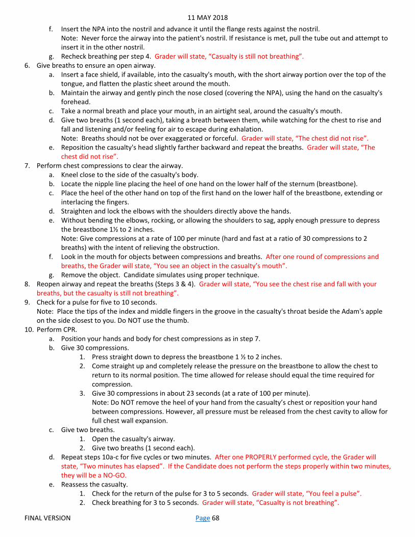
11 MAY 2018
FINAL VERSION Page 68
f. Insert the NPA into the nostril and advance it until the flange rests against the nostril. Note: Never force the airway into the patient's nostril. If resistance is met, pull the tube out and attempt to insert it in the other nostril.
g. Recheck breathing per step 4. Grader will state, “Casualty is still not breathing”. 6. Give breaths to ensure an open airway.
a. Insert a face shield, if available, into the casualty's mouth, with the short airway portion over the top of the tongue, and flatten the plastic sheet around the mouth.
b. Maintain the airway and gently pinch the nose closed (covering the NPA), using the hand on the casualty's forehead.
c. Take a normal breath and place your mouth, in an airtight seal, around the casualty's mouth. d. Give two breaths (1 second each), taking a breath between them, while watching for the chest to rise and
fall and listening and/or feeling for air to escape during exhalation. Note: Breaths should not be over exaggerated or forceful. Grader will state, “The chest did not rise”.
e. Reposition the casualty's head slightly farther backward and repeat the breaths. Grader will state, “The chest did not rise”.
7. Perform chest compressions to clear the airway. a. Kneel close to the side of the casualty's body. b. Locate the nipple line placing the heel of one hand on the lower half of the sternum (breastbone). c. Place the heel of the other hand on top of the first hand on the lower half of the breastbone, extending or
interlacing the fingers. d. Straighten and lock the elbows with the shoulders directly above the hands. e. Without bending the elbows, rocking, or allowing the shoulders to sag, apply enough pressure to depress
the breastbone 1½ to 2 inches. Note: Give compressions at a rate of 100 per minute (hard and fast at a ratio of 30 compressions to 2 breaths) with the intent of relieving the obstruction.
f. Look in the mouth for objects between compressions and breaths. After one round of compressions and breaths, the Grader will state, “You see an object in the casualty’s mouth”.
g. Remove the object. Candidate simulates using proper technique. 8. Reopen airway and repeat the breaths (Steps 3 & 4). Grader will state, “You see the chest rise and fall with your
breaths, but the casualty is still not breathing”. 9. Check for a pulse for five to 10 seconds.
Note: Place the tips of the index and middle fingers in the groove in the casualty's throat beside the Adam's apple on the side closest to you. Do NOT use the thumb.
10. Perform CPR. a. Position your hands and body for chest compressions as in step 7. b. Give 30 compressions.
1. Press straight down to depress the breastbone 1 ½ to 2 inches. 2. Come straight up and completely release the pressure on the breastbone to allow the chest to
return to its normal position. The time allowed for release should equal the time required for compression.
3. Give 30 compressions in about 23 seconds (at a rate of 100 per minute). Note: Do NOT remove the heel of your hand from the casualty’s chest or reposition your hand between compressions. However, all pressure must be released from the chest cavity to allow for full chest wall expansion.
c. Give two breaths. 1. Open the casualty's airway. 2. Give two breaths (1 second each).
d. Repeat steps 10a-c for five cycles or two minutes. After one PROPERLY performed cycle, the Grader will state, “Two minutes has elapsed”. If the Candidate does not perform the steps properly within two minutes, they will be a NO-GO.
e. Reassess the casualty. 1. Check for the return of the pulse for 3 to 5 seconds. Grader will state, “You feel a pulse”. 2. Check breathing for 3 to 5 seconds. Grader will state, “Casualty is not breathing”.

11 MAY 2018
FINAL VERSION Page 69
f. Give breaths at the rate of one every 5 to 6 seconds (10 to 12 breaths per minute). Note: breaths should not be over exaggerated or forceful. After the Candidate has demonstrated PROPER performance, Grader will state, “Two minutes has elapsed”. If the Candidate does not perform the steps properly within two minutes, they will be a NO-GO.
g. Recheck for pulse and breathing. Grader will state, “The casualty is breathing and conscious”. 11. Place the casualty in the recovery position (by rolling him/her as a single unit onto his/her side, placing the hand of
his/her upper arm under his/her chin, and flexing his/her upper leg.) until help arrives. Watch the casualty closely for life-threatening conditions, maintain an open airway, and check for other injuries.
12. Candidate will state that if the casualty’s condition deteriorates, they will continue CPR until: a. The breathing and pulse returns. b. They are relieved or stopped by a qualified person. c. They are physically unable to continue.
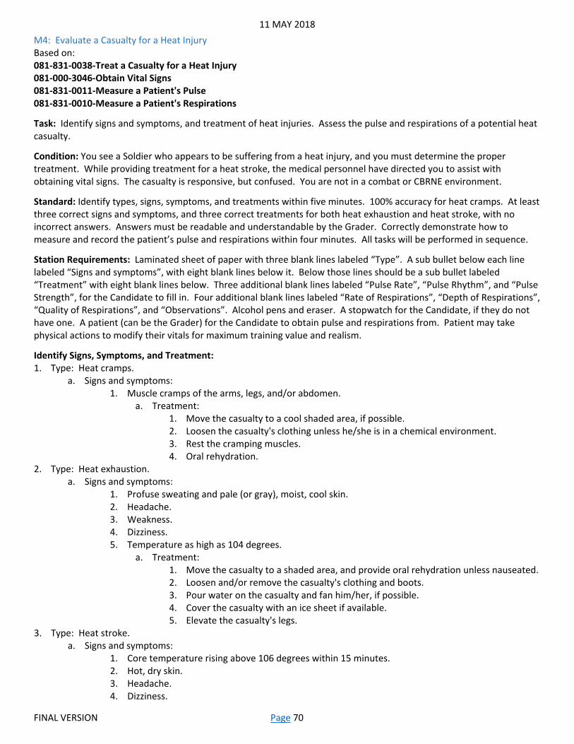
11 MAY 2018
FINAL VERSION Page 70
M4: Evaluate a Casualty for a Heat Injury Based on: 081-831-0038-Treat a Casualty for a Heat Injury 081-000-3046-Obtain Vital Signs 081-831-0011-Measure a Patient's Pulse 081-831-0010-Measure a Patient's Respirations
Task: Identify signs and symptoms, and treatment of heat injuries. Assess the pulse and respirations of a potential heat casualty.
Condition: You see a Soldier who appears to be suffering from a heat injury, and you must determine the proper treatment. While providing treatment for a heat stroke, the medical personnel have directed you to assist with obtaining vital signs. The casualty is responsive, but confused. You are not in a combat or CBRNE environment.
Standard: Identify types, signs, symptoms, and treatments within five minutes. 100% accuracy for heat cramps. At least three correct signs and symptoms, and three correct treatments for both heat exhaustion and heat stroke, with no incorrect answers. Answers must be readable and understandable by the Grader. Correctly demonstrate how to measure and record the patient’s pulse and respirations within four minutes. All tasks will be performed in sequence.
Station Requirements: Laminated sheet of paper with three blank lines labeled “Type”. A sub bullet below each line labeled “Signs and symptoms”, with eight blank lines below it. Below those lines should be a sub bullet labeled “Treatment” with eight blank lines below. Three additional blank lines labeled “Pulse Rate”, “Pulse Rhythm”, and “Pulse Strength”, for the Candidate to fill in. Four additional blank lines labeled “Rate of Respirations”, “Depth of Respirations”, “Quality of Respirations”, and “Observations”. Alcohol pens and eraser. A stopwatch for the Candidate, if they do not have one. A patient (can be the Grader) for the Candidate to obtain pulse and respirations from. Patient may take physical actions to modify their vitals for maximum training value and realism.
Identify Signs, Symptoms, and Treatment: 1. Type: Heat cramps.
a. Signs and symptoms: 1. Muscle cramps of the arms, legs, and/or abdomen.
a. Treatment: 1. Move the casualty to a cool shaded area, if possible. 2. Loosen the casualty's clothing unless he/she is in a chemical environment. 3. Rest the cramping muscles. 4. Oral rehydration.
2. Type: Heat exhaustion. a. Signs and symptoms:
1. Profuse sweating and pale (or gray), moist, cool skin. 2. Headache. 3. Weakness. 4. Dizziness. 5. Temperature as high as 104 degrees.
a. Treatment: 1. Move the casualty to a shaded area, and provide oral rehydration unless nauseated. 2. Loosen and/or remove the casualty's clothing and boots. 3. Pour water on the casualty and fan him/her, if possible. 4. Cover the casualty with an ice sheet if available. 5. Elevate the casualty's legs.
3. Type: Heat stroke. a. Signs and symptoms:
1. Core temperature rising above 106 degrees within 15 minutes. 2. Hot, dry skin. 3. Headache. 4. Dizziness.

11 MAY 2018
FINAL VERSION Page 71
5. Nausea. 6. Confusion. 7. Weakness. 8. Pulse and respirations are weak and rapid.
a. Treatment: 1. Cool the casualty with any means available, even before taking the clothes off. 2. Remove the casualty's outer garments and/or protective clothing. 3. Lay the casualty down and elevate his/her legs. 4. Immerse the casualty in cold water, or cover with an ice sheet if available. 5. Evacuate the casualty.
Assess and Record a Patient’s Pulse and Respirations: 1. Obtain pulse.
a. Position the patient so the pulse site is accessible. b. Palpate (feel) the pulse site.
1. Place the tips of your index and middle fingers on the pulse site. Do not use your thumb to palpate a pulse as your thumb has its own pulse.
2. Apply moderate pressure with your fingers to palpate the pulse. Note: In responsive patients, older than 1 year, you should palpate the radial pulse at the wrist. In unresponsive patients, older than 1 year, you should palpate the carotid pulse at the neck.
c. Count the number of pulses felt in a 30 second period and multiply by two. A pulse that is weak, difficult to palpate, or irregular should be palpitated and counted for one full minute.
d. Evaluate the pulse rhythm (regularity). 1. Regular rhythm.
a. Usually easy to find. b. Has a regular rate and rhythm. c. Varies with the individual.
2. Irregular rhythm (any change from a regular beating pattern). Note: If the pulse is irregular or intermittent, you should palpate a second pulse at the carotid or femoral site.
e. Evaluate the pulse strength. 1. Strong (full) pulse.
a. Usually easy to find. b. Beats evenly and forcefully.
2. Bounding (stronger than normal) pulse. a. Easy to find. b. Exceptionally strong heartbeats that make the arteries difficult to compress.
3. Weak (thready) pulse. a. Usually difficult to find. b. Weak and thin.
2. Record the rate (__BPM), rhythm (Regular or Irregular), strength (Strong, Bounding, or Weak), and any significant deviations from normal.
3. Obtain respirations. a. Remove any clothing or equipment that would prevent or hinder the observation of the respirations. b. Count the number of times the chest rises (inspiration) and returns to its normal position (expiration). Each
respiratory cycle (inspiration/expiration) counts as one respiration. Note: The patient should not be aware that his/her respirations are being counted. The conscious patient that is aware his/her respirations are being counted will often alter his/her respiratory rate by breathing slower and deeper. If a patient is speaking, this too may result in an inaccurate assessment of respirations. A common method is to hold the patient’s wrist as though taking a pulse again, while crossing the patient’s arm across the patient’s chest so as to be able to feel and observe the chest rise and fall.
c. Evaluate the respirations. 1. Depth.

11 MAY 2018
FINAL VERSION Page 72
a. Normal: deep, even movement of the chest. b. Shallow: minimal rise and fall of the chest and abdomen. c. Labored: increased effort to breathe, with possible gasping.
2. Quality (character). a. Normal: effortless, automatic, regular rate, even depth, noiseless, and free of discomfort. b. Dyspnea: difficult or labored breathing. c. Tachypnea: rapid respiratory rate; usually is a rate exceeding 24 breaths/min (adult). d. Noisy: snoring, rattling, wheezing (whistling), or grunting. e. Apnea: temporary absence of breathing.
3. Observe for physical characteristics of abnormal respirations. a. Appearance: the patient may appear restless, anxious, pale, ashen, or cyanotic (blue skin
color). b. Position: the patient may alter his/her position by leaning forward with his/her hands on
legs (tripod position) or may be unable to breathe while lying down. 4. Record the rate (__RPM), depth (Normal, Shallow, or Labored), Quality (Normal, Labored, Rapid, Noisy, or Apnea) of
respirations and any physical observations (Appearances or Positions) noted.
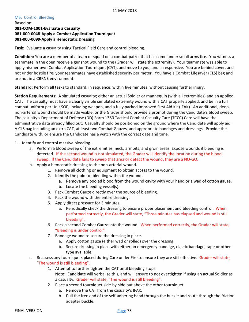
11 MAY 2018
FINAL VERSION Page 73
M5: Control Bleeding Based on: 081-COM-1001-Evaluate a Casualty 081-000-0048-Apply a Combat Application Tourniquet 081-000-0099-Apply a Hemostatic Dressing
Task: Evaluate a casualty using Tactical Field Care and control bleeding.
Condition: You are a member of a team or squad on a combat patrol that has come under small arms fire. You witness a teammate in the open receive a gunshot wound to the (Grader will state the extremity). Your teammate was able to apply his/her own Combat Application Tourniquet (CAT), and move to you, and is responsive. You are behind cover, and not under hostile fire; your teammates have established security perimeter. You have a Combat Lifesaver (CLS) bag and are not in a CBRNE environment.
Standard: Perform all tasks to standard, in sequence, within five minutes, without causing further injury.
Station Requirements: A simulated casualty; either an actual Soldier or mannequin (with all extremities) and an applied CAT. The casualty must have a clearly visible simulated extremity wound with a CAT properly applied, and be in a full combat uniform per Unit SOP, including weapon, and a fully packed Improved First Aid Kit (IFAK). An additional, deep, non-arterial wound should be made visible, or the Grader should provide a prompt during the Candidate’s blood sweep. The casualty’s Department of Defense (DD) Form 1380 Tactical Combat Casualty Care (TCCC) Card will have the administrative data already filled out. Casualty should be positioned on the ground where the Candidate will apply aid. A CLS bag including an extra CAT, at least two Combat Gauzes, and appropriate bandages and dressings. Provide the Candidate with, or ensure the Candidate has a watch with the correct date and time.
1. Identify and control massive bleeding. a. Perform a blood sweep of the extremities, neck, armpits, and groin areas. Expose wounds if bleeding is
detected. If the second wound is not simulated, the Grader will identify the location during the blood sweep. If the Candidate fails to sweep that area or detect the wound, they are a NO-GO.
b. Apply a hemostatic dressing to the non-arterial wound. 1. Remove all clothing or equipment to obtain access to the wound. 2. Identify the point of bleeding within the wound.
a. Remove any pooled blood from the wound cavity with your hand or a wad of cotton gauze. b. Locate the bleeding vessel(s).
3. Pack Combat Gauze directly over the source of bleeding. 4. Pack the wound with the entire dressing. 5. Apply direct pressure for 3 minutes.
a. Periodically check the dressing to ensure proper placement and bleeding control. When performed correctly, the Grader will state, “Three minutes has elapsed and wound is still bleeding”.
6. Pack a second Combat Gauze into the wound. When performed correctly, the Grader will state, “Bleeding is under control”.
7. Bandage wound to secure the dressing in place. a. Apply cotton gauze (either wad or rolled) over the dressing. b. Secure dressing in place with either an emergency bandage, elastic bandage, tape or other
type available. c. Reassess any tourniquets placed during Care under Fire to ensure they are still effective. Grader will state,
“The wound is still bleeding”. 1. Attempt to further tighten the CAT until bleeding stops.
Note: Candidate will verbalize this, and will ensure to not overtighten if using an actual Soldier as a casualty. Grader will state, “The wound is still bleeding”.
2. Place a second tourniquet side-by-side but above the other tourniquet a. Remove the CAT from the casualty’s IFAK. b. Pull the free end of the self-adhering band through the buckle and route through the friction
adapter buckle.

11 MAY 2018
FINAL VERSION Page 74
Note: On an arm wound, it is not necessary to route the strap through the friction adapter. c. Pull the self-adhering band tight around the extremity and fasten it back on itself as tightly
as possible. d. Twist the windlass until the bleeding stops.
Note: Candidate will verbalize this, and will ensure to not overtighten if using an actual Soldier as a casualty.
e. Lock the windlass in place within the windlass clip. f. Secure the windlass with the windlass strap. g. Assess for absence of a distal pulse.
Note: Candidate should perform and verbalize with proper technique. Pulse must be taken with skin to skin contact, and not using their thumb.
h. Place a "T" and the time of the application on the casualty with a marker (provided in casualty’s IFAK). Note: This can be simulated and verbalized, or a piece of lamination can be applied to the casualty’s forehead so each Candidate can perform the task.
i. Secure the CAT in place with tape (provided in casualty’s IFAK).

11 MAY 2018
FINAL VERSION Page 75
M6: Evaluate and Treat a Casualty for a Spinal Injury and Shock Based on: 081-COM-1001-Evaluate a Casualty 081-000-0083-Apply a Cervical Collar 081-831-0012-Measure a Patient's Blood Pressure 081-000-3046-Obtain Vital Signs 081-COM-1005-Perform First Aid to Prevent or Control Shock 081-000-0013-Initiate a Tactical Combat Casualty Care Card
Task: Identify the signs and symptoms of shock. Evaluate and treat a casualty for spinal injury and shock.
Condition: You are a member of a platoon within a secure Forward Operating Base (FOB) in a non-CBRNE environment. You are assisting medical personnel with an injury to a fellow service member, and preparing them for evacuation while waiting on the Medical Evacuation (MEDEVAC). Another Soldier states that he/she witnessed the casualty fall from a guard tower, and suspects internal bleeding and a spinal injury. He/she goes on to state that after initially acting fine, the injured Soldier began complaining of nausea, difficulty breathing, and abdominal pain. The injured Soldier is laying on a litter when you arrive, and is alert to pain only. The uninjured Soldier is available to assist you with spinal stabilization and movement of the casualty while you and the medic provide treatment. The medic directs you to apply a Cervical Collar, obtain the patient’s blood pressure, and treat for shock.
Standard: Identify at least five signs and symptoms of shock with no incorrect answers within one minute. Apply a cervical collar and treat for shock to standard, in sequence, within five minutes, without causing further injury.
Station Requirements: A simulated casualty in a field uniform. A Department of Defense (DD) Form 1380 Tactical Combat Casualty Care (TCCC) Card with the administrative data already filled out. A Basic Life Support (BLS) bag with adjustable Cervical Collars (one pediatric and one adult), set to an incorrect size. Blood Pressure (BP) cuff (at least two sizes) and stethoscope. Casualty should be positioned on the litter where the Candidate will apply aid. Additional Soldier (if available) to assist. Laminated sheet of paper with nine blank lines, alcohol pens, and eraser. Provide the Candidate with, or ensure the Candidate has a stopwatch.
Identify Signs and Symptoms of Shock: 1. Sweaty but cool skin. 2. Pale skin. 3. Restlessness or nervousness. 4. Thirst. 5. Severe bleeding. 6. Confusion. 7. Rapid breathing. 8. Blotchy blue skin. 9. Nausea and/or vomiting.
Apply a Cervical Collar and Treat for Shock: 1. Apply Cervical Collar
a. Have the other Soldier kneel at the casualty's head and manually apply in-line stabilization of the head and neck. If the assistant is notional, the Grader will state, “The other Soldier has the head and neck in-line and immobilized”.
b. Reassure the casualty and explain the procedure to him/her. c. Determine the size of collar to apply.
1. The front height of the collar should fit between the point of the chin and the chest at the suprasternal notch.
2. Once in place, the collar should rest on the shoulder girdle and provide firm support under both sides of the mandible without obstructing the airway or any ventilation efforts.
3. If the collar is too large, the casualty's neck may be placed in hyperextension. 4. If the collar is too small, the casualty's neck may be placed in hyperflexion.
d. Size the collar based on the manufacturer instructions.

11 MAY 2018
FINAL VERSION Page 76
e. Apply the collar to a supine casualty. 1. Ensure the other Soldier maintains in-line stabilization. 2. Set the collar in place around the neck. 3. Secure the Velcro strap in place. 4. Maintain manual stabilization of the head and neck until the casualty is immobilized on a long
spine board. 2. Obtain blood pressure.
a. Explain the procedure to the patient. 1. The length of time the procedure will take. 2. The site to be used (arm). 3. The physical sensations the patient will feel.
b. Select the proper size of BP cuff. The cuff width should wrap around the arm 1-1.5 times and take up two-thirds of the upper arm length, using the brachial artery. A cuff that is too small may result in falsely high readings; a cuff that is too large may result in falsely low readings.
c. Check the equipment. 1. Ensure the cuff is completely deflated and fully retighten the one-way valve thumbscrew. 2. Ensure the BP gauge is reading zero.
d. Position the patient and cuff. 1. Maintain supine position and spinal immobilization. 2. With the patient's arm extended, at approximately heart level and with the palm up, place the
cuff over the brachial artery. Ensure the lower edge of the cuff is 1-2 inches above the elbow and the bladder portion is over the artery.
3. Wrap the cuff just tightly enough to prevent slippage. 4. Support the arm so it is in a relaxed state.
e. Palpate the brachial artery to determine where to place the stethoscope. f. Place the diaphragm of the stethoscope over the pulse site and hold it firmly pressed against the artery with
the fingers of your non-dominant hand. g. With the valve closed tightly, inflate the cuff using the ball-pump until the cuff reads at least 160 mm Hg
(Millimeters of mercury) or until you no longer hear the pulse sounds. Continue pumping to increase the cuff's pressure by an additional 30 mm Hg. Note: The cuff should not remain inflated for more than 2 minutes.
h. Determine the blood pressure reading. 1. Rotate the thumbscrew in a counter clockwise motion, allowing the cuff to deflate slowly at about
3 mm Hg per second. 2. Watch the gauge and listen carefully. Note the patient's systolic blood pressure as the first distinct
"taps" or "thumps" of the pulse waves that can be heard clearly. 3. Continue to watch the gauge and note the reading where the sound changes again or becomes
muffled or disappears. This will be the diastolic blood pressure. 4. As soon as the pulse sounds cease, open the valve by rotating the thumbscrew and release the
remaining air rapidly. 5. Record the blood pressure on the TCCC Card.
a. Record the systolic reading over the diastolic reading, for example 120/80. b. Record all readings in even numbers. c. Record the blood pressure readings with the time it was taken on the TCCC Card from the
casualty’s IFAK. 3. Treat for hemorrhagic shock.
a. Position the casualty. 1. Move the casualty under a permanent or improvised shelter to shade him/her from direct
sunlight. Note: Secure casualty on the litter before moving. If no assistant is available, Candidate will verbalize, but still ensure to secure the casualty on the litter.
2. Maintain supine position and spinal immobilization.

11 MAY 2018
FINAL VERSION Page 77
b. Loosen clothing at the neck, waist, or anywhere it is binding. c. Prevent the casualty from getting chilled or overheated. Using a blanket or clothing, cover the casualty to
avoid loss of body heat by wrapping completely around the casualty, underneath the litter straps. Re-secure the patient on the litter.
d. Calm and reassure the casualty. e. Watch the casualty closely for life-threatening conditions and check for other injuries.
4. Correctly record all treatments on a TCCC Card. a. Front of card.
1. Evacuation (EVAC) - Mark an “X” on the casualty’s evacuation priority/precedence (Urgent; Priority; or Routine).
2. Date - Write date of injury in DD-MMM-YY format. For example, “29-JUN-13”. 3. Time - Write 24 hour time of injury, and indicate whether local (L) or Zulu (Z) time. For example,
“1300Z”. 4. Mechanism of Injury - Mark an “X” on the mechanism or cause of injury (artillery, blunt, burn, fall,
grenade, gunshot wound (GSW), improvised explosive device (IED), landmine, motor vehicle crash/collision (MVC), rocket propelled grenade (RPG), other (specify)). Mark all that apply.
5. Injury - Mark an “X” at the site of the injury(ies) on the body picture. If multiple mechanisms of injury and multiple injuries, draw a line between the mechanism of injury and the anatomical site of the injury. (Spinal injury and internal bleeding).
6. Time - Write time of vital signs taken. 7. Blood Pressure - Write casualty's blood pressure. 8. AVPU - Write casualty's level of consciousness (AVPU: Alert, responds to Verbal stimulus, responds
to Pain stimulus, Unresponsive). b. Back of card.
1. Evacuation (EVAC) - Mark an “X” on the casualty’s evacuation priority/precedence (Urgent; Priority; or Routine).
2. Other - Mark an “X” for other treatments administered (combat pill pack, eye shield (mark right (R) or left (L)), splint, hypothermia prevention) and type of device(s) used. (Cervical collar).
3. Notes - Use this space to record any other pertinent information and/or clarifications. (Patient exhibiting signs and symptoms of shock).
4. First Responder Name - Print the first responder’s name (Last, First). 5. First Responder Last 4 - Write last four numbers of first responder’s Social Security number.

11 MAY 2018
FINAL VERSION Page 78
M7: Apply an Occlusive Dressing and Perform a Needle Chest Decompression Based on: 081-833-0069-Apply an Occlusive Dressing 081-833-3007-Perform Needle Chest Decompression 081-833-0164-Measure a Patient's Pulse Oxygen Saturation 081-000-0013-Initiate a Tactical Combat Casualty Care Card
Task: Treat a chest wound and tension pneumothorax.
Condition: You are a member of a team or squad on a combat patrol that has come under small arms fire in a non-CBRNE environment. You witness a teammate in the open receive a gunshot wound to upper body. Your teammate was able to move to you, and is responsive. You are behind cover, and not under hostile fire; your teammates have established security perimeter. You must begin treatment while waiting on medical personnel to arrive. The injured Soldier is alert and complaining of difficulty breathing. Another Soldier is helping you finish the casualty assessment, and is obtaining the other vital signs.
Standard: Perform all tasks to standard, in sequence, within five minutes, without causing further injury.
Station Requirements: A simulated casualty (mannequin with all extremities) in a full combat uniform per Unit SOP, including weapon, and a fully packed Improved First Aid Kit (IFAK). Casualty must have two simulated gunshot wounds to the upper body; one on the front (entry) and one on the back (exit). A TCCC Card with the administrative data already filled out. A Basic Life Support (BLS) bag with occlusive dressings and/or materials with which to improvise. Pulse oximetry device (fingertip) and alcohol swabs. Laminated sheet of paper with nine blank lines, alcohol pens, and eraser. Provide the Candidate with, or ensure the Candidate has a watch with the correct date and time.
1. Apply occlusive dressing. a. Expose the injuries. b. Apply an occlusive dressing to the entry wound.
1. Upon full expiration, cover the wound with large, occlusive material dressing, covering the first wound encountered.
2. Ensure the material extends 2 inches beyond the edge of the wound. 3. Tape all four sides of the dressing.
c. Log roll the casualty or have them sit up and examine the back for an exit wound. d. Apply an occlusive dressing to the exit wound using the same standards as Step b.
2. Verify the presence of tension pneumothorax by checking for indications of the condition and verbalizing each step. a. Question the casualty about difficulty in breathing, pain on the affected side, or coughing up blood, and
observe for signs of progressive respiratory distress. Grader will state, “Casualty is gasping for air and has pain on the wound side”.
b. Observe the casualty’s bare chest for respiratory rate depth, and abdomen for progressive distension. Grader will state, “Casualty has poor respiratory rate and depth, and the abdomen is mildly distended”.
c. Look for mediastinal shift manifested as a tracheal deviation and/or jugular distension. Grader will state, “Casualty does not have tracheal deviation, but has mild jugular distension”.
d. Look at and feel the patient's chest for signs of air in the chest wall (subcutaneous emphysema). Grader will state, “You feel a crackling sensation on the casualty’s chest”.
e. Check for unilateral distension and chest expansion (excursion). 1. Place one hand on the affected side. 2. Place the other hand on the unaffected side. 3. Observe the height of each hand as the chest rises and falls. 4. Determine if the height of the hand on the affected side is greater during expiration than the
height of the hand on the unaffected side. Grader will state, “The hand on the unaffected side is higher than the other”.
f. Look for deep cyanosis. Grader will state, “You observe mild cyanosis”. g. Look for signs and symptoms of shock. Grader will state, “You observe two signs of shock-(Grader choice)”.
3. Locate the insertion site. Locate the second intercostal space (between the second and third ribs) at the midclavicular line (approximately in line with the nipple) on the affected side of the patient's chest.

11 MAY 2018
FINAL VERSION Page 79
4. Thoroughly cleanse a 3 to 4 inch area around the insertion site. Begin in the center and work outward using a circular motion.
5. Apply a commercial needle decompression kit according to manufacturer’s instructions or improvise by inserting a large bore (10 to 14 gauge) needle with attached catheter (steps below).
a. Place the needle tip, bevel up, on the insertion site (2nd intercostal space, midclavicular line). b. Lower the proximal end of the needle to permit the tip to enter the skin just above the third rib margin. c. Firmly insert the needle into the skin over the third rib, until the pleura has been penetrated, as evidenced
by feeling a "pop" as the needle enters the pleural space. d. Remove the needle and discard per unit SOP.
6. Decompress the affected side by aspirating as much air as is necessary to relieve the patient's acute symptoms. 7. Apply a commercial one-way flutter valve according to manufacturer’s instructions or improvise one (steps below).
a. Cut a finger casing from a sterile glove. b. Cut off the fingertip. c. Tie or tape the finger casing to the needle hub. d. Check the operation of the improvised flutter valve.
1. Ensure that air passes through the needle-valve assembly and improvised flutter valve on expiration.
2. Ensure that the flutter valve collapses against itself on inspiration. e. Secure the catheter to the chest.
8. Measure pulse and O2 SAT. Candidate will perform this step on themselves or another soldier since the casualty must be a mannequin.
a. Wipe the index, middle, or ring finger tip with alcohol to ensure it is clean and dry. b. Apply the sensor. c. Document the readings on the TCCC Card.
9. Record all treatments on the TCCC Card. a. Front of card.
1. Evacuation (EVAC) - Mark an “X” on the casualty’s evacuation priority/precedence (Urgent; Priority; or Routine).
2. Date - Write date of injury in DD-MMM-YY format. For example, “29-JUN-13”. 3. Time - Write 24 hour time of injury, indicating whether local (L) or Zulu (Z) time, such as “1300Z”. 4. Mechanism of Injury - Mark an “X” on the mechanism or cause of injury (artillery, blunt, burn, fall,
grenade, gunshot wound (GSW), improvised explosive device (IED), landmine, motor vehicle crash/collision (MVC), rocket propelled grenade (RPG), other (specify)). Mark all that apply.
5. Injury - Mark an “X” at the site of the injury(ies) on the body picture. For burn injuries, circle the burn percentage(s) on the figure. If multiple mechanisms of injury and multiple injuries, draw a line between the mechanism of injury and the anatomical site of the injury.
6. Time - Write time of vital signs taken. 7. Pulse (rate & location) - Write casualty's pulse rate. 8. O2 Sat - Write casualty's O2 SAT. 9. AVPU - Write casualty's level of consciousness (AVPU: Alert, responds to Verbal stimulus, responds
to Pain stimulus, Unresponsive). b. Back of card.
1. Evacuation (EVAC) - Mark an “X” on the casualty’s evacuation priority/precedence (Urgent; Priority; or Routine).
2. C - Mark an “X” for all Circulation hemorrhage control interventions. For tourniquets (TQ), mark category (Extremity, Junctional and/or Truncal) and write name of TQ(s) used. For dressings, mark category (Hemostatic, Pressure, and/or Other) and write type of dressing(s) used.
3. B - Mark an “X” for all Breathing interventions oxygen (O2), needle decompression (Needle-D), Chest-Tube, (Chest-Seal) and write type of device(s) used.
4. First Responder Name - Print the first responder’s name (Last, First). 5. First Responder Last 4 - Write last four numbers of first responder’s Social Security number.

11 MAY 2018
FINAL VERSION Page 80
M8: Perform First Aid for an Open Head Wound in a CBRNE Environment Based on: 081-831-1033-Perform First Aid for an Open Head Wound
Task: Treat a casualty with an open head wound.
Condition: You are a member of a team or squad on a combat patrol in a CBRNE environment that has come under indirect fire. You witness a teammate in the open receive fragmentation to the head. Your teammate was able to move to you, and is responsive. You are behind cover, and not under hostile fire; your teammates have established security perimeter. You must begin treatment while waiting on medical personnel to arrive. The injured Soldier is conscious and alert. You are in Mission Oriented Protective Posture (MOPP) level three.
Standard: Perform all tasks to standard, in sequence, within five minutes, without causing further injury.
Station Requirements: A simulated casualty (mannequin with all extremities) in a full MOPP level three combat uniform per Unit SOP, including weapon, and a fully packed Improved First Aid Kit (IFAK). Casualty must have a simulated head wound.
1. Check the casualty's level of consciousness. a. "What is your name?" b. "Where are you?" c. "What is today's date (day, month, and year)?"
Grader states, “The casualty replies appropriately”. 2. Position the casualty.
a. Have the casualty sit up if able. b. Turn his/her head to the side or position the casualty on his/her side (opposite the wound) if the wound is
bleeding into the mouth or throat. 3. Expose the wound by removing the casualty's helmet, if necessary, but retaining all MOPP garments.
Do NOT attempt to clean the wound or remove a protruding object. Do NOT put unnecessary pressure on the wound or attempt to push any brain matter back into the head (skull). Do NOT apply a pressure dressing. Do NOT give the casualty any food or drink. Do NOT touch the white (sterile) side of the dressing. Do NOT allow it to come into contact with any surface other than the wound.
4. The following procedures are for applying a field dressing. If you are applying an emergency bandage, follow the general procedure for other bleeding wounds, while observing general guidelines and precautions.
a. Apply the casualty's dressing to a wound on the forehead or back of head. 1. Apply the dressing, white side down, directly over the wound with the tails extending toward the
sides of the head. 2. Wrap the tails, one at a time, around the head in opposite directions, making sure the tails cover
the dressing but not the eyes and ears. 3. Tie the tails at the side of the head using a nonslip knot.
b. Apply the casualty's dressing to a wound on the top of head. 1. Apply the dressing, white side down, directly over the wound. 2. Wrap one tail down under the chin and bring it up in front of the ear over the dressing to a point
just above, and in front of, the opposite ear. Note: Ensure the tails remain wide and close to the front of the chin to avoid choking the casualty.
3. Wrap the other tail down under the chin in the opposite direction and up the side of the head to meet the first tail.
4. Cross the tails. 5. Wrap one tail across the forehead above the eyebrows to a point just above and in front of the
opposite ear. 6. Wrap the other tail above the ear, low over the back of the head, and above the opposite ear to
meet the other tail.

11 MAY 2018
FINAL VERSION Page 81
7. Tie the tails using a nonslip knot. c. Apply the casualty's dressing to a wound on the side of the head or cheek.
1. Apply the dressing, white side down, directly over the wound with the tails extending up and down.
2. Wrap the top tail over the top of the head, down in front of the ear, under the chin, and up over the dressing to a point just above the ear.
3. Wrap the other tail in the opposite direction to meet the first tail. 4. Cross the tails and complete the procedure as follows:
a. Wrap one tail across the forehead above the eyebrows to a point just above, and in front of, the opposite ear.
b. Wrap the other tail above the ear, low over the back of the head, and above the opposite ear to meet the other tail.
c. Tie the tails using a nonslip knot. 5. Watch the casualty for life-threatening conditions, check for other injuries, and treat for shock. Seek medical aid.

11 MAY 2018
FINAL VERSION Page 82
M9: Treat an Open Abdominal Wound and Eye Injuries Based on: 081-COM-1001-Evaluate a Casualty 081-831-1025-Perform First Aid for an Open Abdominal Wound 081-000-0127-Initiate Treatment for an Open Abdominal Wound 081-833-0057-Treat Lacerations, Contusions, and Extrusions of the Eye 081-COM-1055-Apply a Fox Eye Shield
Task: Perform first aid for an abdominal and eye injury.
Condition: You are a member of a team or squad on a mounted combat patrol. You witness the explosion of an Improvised Explosive Device (IED), which immobilized the convoy’s lead vehicle. You are assisting medical personnel with triage and treatment. You are behind cover, and not under hostile fire; your teammates have established a security perimeter. The medic has performed a rapid trauma assessment on the first patient, determining that there are no other immediate, life threatening injuries. The medic has directed you to treat the casualty’s open abdominal wound and eye injury (Grader will state type of eye injury if it is not clearly simulated). You have a Combat Lifesaver (CLS) bag and are not in a CBRNE environment.
Standard: Perform all tasks to standard, in sequence, within six minutes, without causing further injury.
Station Requirements: A simulated casualty; either an actual Soldier or mannequin (with all extremities). The casualty must have a clearly visible simulated abdominal wound (with simulated organs or intestines outside the body) and an eye injury (Grader will select one of the eye injury options), and be in a full combat uniform per Unit SOP, including weapon, and a fully packed Improved First Aid Kit (IFAK). Casualty should be positioned on the ground where the Candidate will apply aid. A CLS bag including all appropriate bandages, dressings, and materials needed to improvise if required.
1. Treat abdominal wound. a. Check for both entry and exit wounds (there should only be one) by sitting casualty up or rolling to the side. b. Position the casualty.
1. On back/face up. 2. Flex knees. 3. Turn head to the side and keep airway clear in case of vomiting.
c. Expose the wound. d. Pick up any organs that are on the ground.
1. Use a clean, dry dressing or the cleanest material available and gently pick up the organs without touching them with your bare hands. Note: Do NOT probe, clean, or try to remove any foreign object from the abdomen. Do NOT push organs back inside the body.
2. Place the organs on top of the casualty's abdomen. e. Apply a sterile abdominal dressing.
Note: Protruding abdominal organs should be kept moist to prevent the tissue from drying out. A moist, sterile dressing should be applied if available. Note: If there is an object extending from the wound, do NOT remove it. Place as much of the wrapper over the wound as possible without dislodging or moving the object. Do NOT place the wrapper over the object.
1. Using the sterile side of the dressing, or other clean material, place any protruding organs near the wound.
2. Ensure that the dressing is large enough to cover the entire mass of protruding organs or area of the wound.
3. If large enough to cover the affected area, place the sterile side of the plastic wrapper directly over the wound.
4. Place the dressing directly on top of the wound or plastic wrapper, if used. Note: Do not apply pressure on the wound or expose internal parts.
5. Tie the dressing tails loosely at the casualty's side. For an emergency bandage, secure the hooking ends of the closure bar into the elastic bandage.
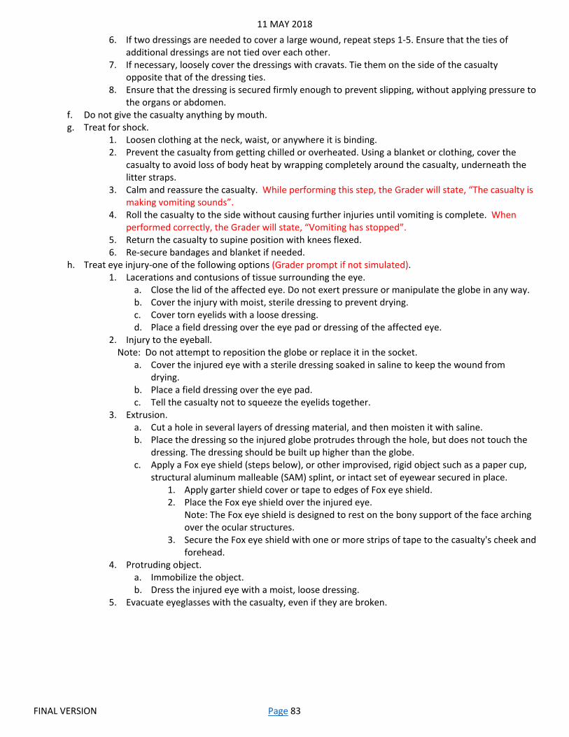
11 MAY 2018
FINAL VERSION Page 83
6. If two dressings are needed to cover a large wound, repeat steps 1-5. Ensure that the ties of additional dressings are not tied over each other.
7. If necessary, loosely cover the dressings with cravats. Tie them on the side of the casualty opposite that of the dressing ties.
8. Ensure that the dressing is secured firmly enough to prevent slipping, without applying pressure to the organs or abdomen.
f. Do not give the casualty anything by mouth. g. Treat for shock.
1. Loosen clothing at the neck, waist, or anywhere it is binding. 2. Prevent the casualty from getting chilled or overheated. Using a blanket or clothing, cover the
casualty to avoid loss of body heat by wrapping completely around the casualty, underneath the litter straps.
3. Calm and reassure the casualty. While performing this step, the Grader will state, “The casualty is making vomiting sounds”.
4. Roll the casualty to the side without causing further injuries until vomiting is complete. When performed correctly, the Grader will state, “Vomiting has stopped”.
5. Return the casualty to supine position with knees flexed. 6. Re-secure bandages and blanket if needed.
h. Treat eye injury-one of the following options (Grader prompt if not simulated). 1. Lacerations and contusions of tissue surrounding the eye.
a. Close the lid of the affected eye. Do not exert pressure or manipulate the globe in any way. b. Cover the injury with moist, sterile dressing to prevent drying. c. Cover torn eyelids with a loose dressing. d. Place a field dressing over the eye pad or dressing of the affected eye.
2. Injury to the eyeball. Note: Do not attempt to reposition the globe or replace it in the socket.
a. Cover the injured eye with a sterile dressing soaked in saline to keep the wound from drying.
b. Place a field dressing over the eye pad. c. Tell the casualty not to squeeze the eyelids together.
3. Extrusion. a. Cut a hole in several layers of dressing material, and then moisten it with saline. b. Place the dressing so the injured globe protrudes through the hole, but does not touch the
dressing. The dressing should be built up higher than the globe. c. Apply a Fox eye shield (steps below), or other improvised, rigid object such as a paper cup,
structural aluminum malleable (SAM) splint, or intact set of eyewear secured in place. 1. Apply garter shield cover or tape to edges of Fox eye shield. 2. Place the Fox eye shield over the injured eye.
Note: The Fox eye shield is designed to rest on the bony support of the face arching over the ocular structures.
3. Secure the Fox eye shield with one or more strips of tape to the casualty's cheek and forehead.
4. Protruding object. a. Immobilize the object. b. Dress the injured eye with a moist, loose dressing.
5. Evacuate eyeglasses with the casualty, even if they are broken.
11 MAY 2018
FINAL VERSION Page 84
M10: Treat a Fracture and a Burn Based on: 081-831-1034-Perform First Aid for a Suspected Fracture 081-000-0044-Initiate Treatment for Burns
Task: Perform first aid for a fracture and a burn.
Condition: You are a member of a team or squad on a combat patrol. You witness the explosion of an Improvised Explosive Device (IED) throw several teammates to the ground. You are assisting medical personnel with triage and treatment. You are behind cover, and not under hostile fire; your teammates have established a security perimeter. The medic has performed a rapid trauma assessment on the first patient, determining that there are no other immediate, life threatening injuries. The medic has directed you to treat the casualty’s (Grader states extremity) closed fracture and burn to (Grader states location of burn injury). You have a Combat Lifesaver (CLS) bag and are not in a CBRNE environment.
Standard: Perform all tasks to standard, in sequence, within six minutes, without causing further injury.
Station Requirements: A simulated casualty; either an actual Soldier or mannequin (with all extremities). The casualty must have a clearly visible simulated fracture to an extremity and a burn injury, and be in a full combat uniform per Unit SOP, including weapon, and a fully packed Improved First Aid Kit (IFAK). Casualty should be positioned on the ground where the Candidate will apply aid. A CLS bag including all appropriate bandages, dressings, splints, and materials needed to improvise if required. All Candidates must be provided the same splint/sling/swathe supplies to choose from; the Graders can provide all options or select one type.
1. Treat facture with a splint, sling, or swathe (Grader choice). a. Reassure the casualty and explain the process. b. Loosen any tight or binding clothing. Do NOT remove boots from the casualty unless they are needed to
stabilize a neck injury or there is actual bleeding from the foot. c. Remove all jewelry from the affected limb and place it in the casualty's pocket. Tell the casualty that you are
doing this to prevent further injury if swelling occurs later. d. Check for signs of blood circulation problems below the injury.
1. Check light-skinned persons for color of skin (skin may be pale, white, or a bluish gray color). 2. Check dark-skinned persons by depressing the toenail or fingernail beds and seeing how fast the
color returns. A slower return of color to the injured side indicates a circulation problem. 3. Feel the injured arm or leg to see if it is colder than the uninjured one. 4. Ask the casualty about the presence of numbness, tightness, or a cold sensation.
e. Splint-improvised or SAM splint (Grader choice). Note: SAM splints are used for arms, forearms, or lower legs; no additional padding required. Note: Improvised splints are made from two rigid objects such as straight tree limbs, boards, tent poles, or unloaded rifles. Materials such as cravats, strips of cloth, or belts can be used to secure the rigid objects and keep the fracture immobilized. Materials such as a jacket, blanket, poncho, shelter half, or leafy vegetation can be used to pad the splints. If splinting materials are not available, use the chest wall to immobilize a suspected fracture of the arm and the uninjured leg to immobilize the fractured leg.
1. As a rule, splint the fracture in the position found. a. If there is no circulation below the fracture site, or if the limb is grossly angulated and you
cannot effectively splint it, you may need to gently realign the limb to effectively splint the fracture site. Grader prompt.
b. With one hand supporting the fracture site, use the other hand to grasp the part of the limb farthest from the fracture and gently place traction on it (pull in the direction of the long axis of the bone, like extending a telescope).
2. Make sure the ends of the splints do not press against the groin. Such pressure could interfere with blood circulation.
3. Place one splint on each side of the arm or leg and pad appropriately. Make sure the splints reach beyond the joints above and below the fracture. A single SAM splint may be bent appropriately for smaller fractures such as a wrist.
11 MAY 2018
FINAL VERSION Page 85
4. Tie the splints with improvised (or actual) cravats. a. Do NOT tie any cravats directly over the fracture. b. Gently place at least two cravats above and two cravats below the fracture if possible. c. Tie nonslip knots on the splint away from the injury.
5. Check the splint for tightness. a. Make sure the cravats are tight enough to hold the splinting materials securely in place. b. Recheck circulation below the injury to make sure that circulation is not impaired. c. Make any adjustments to improve circulation without allowing the splint to become
ineffective. f. Sling-actual or improvised (Grader choice).
Note: Make an improvised sling from any non-stretching material (such as a strip of clothing or blanket, poncho, shelter half, belt, or shirttail).
1. Apply the sling so the supporting pressure is on the casualty's uninjured side. 2. Make sure the hand of the supported arm is slightly higher than the elbow. 3. Recheck circulation below the injury to make sure that circulation is not impaired. 4. Make any adjustments to improve circulation without allowing the sling to become ineffective.
g. Swathe. Note: Apply swathes when the casualty has a splinted, suspected fracture of the elbow or leg, or when a suspected fracture cannot be splinted. (Improvise swathes from large pieces of cloth or belts).
1. Place swathes above and/or below the fracture, not over it. 2. Apply swathes to an injured arm by wrapping the swathes over the injured arm, around the
casualty's back, and under the arm on the uninjured side. Tie the ends on the uninjured side. 3. Apply swathes to an injured leg by wrapping the swathes around both legs and tying the swathes
on the uninjured side. 4. Recheck circulation below the injury to make sure that circulation is not impaired. 5. Make any adjustments to improve circulation without allowing the swathe to become ineffective.
2. Treat burn. a. Cut the casualty's clothing away from the burned areas. b. Remove potentially constricting items such as rings and bracelets. c. Apply a dry sterile dressing securely, but not overly tight. d. Cover extensive burns with a sterile sheet, if available, or clean linen.

11 MAY 2018
FINAL VERSION Page 86
Chapter 12-Patrol Lane
P1: Adjust Indirect Fire Based on: 061-283-6003-Adjust Indirect Fire 071-326-0512-Estimate Range
Task: Call for indirect fire. Adjust indirect fire. Fire for effect.
Condition: You are a senior leader in a platoon or company during a traveling over watch movement in a non-CBRNE environment. Your adjacent unit has come under fire from (Grader states type and size of target) and is requesting fire support. You have no Forward Observer in your element. You have a 10 digit grid to your location, and (Grader states type of mortars/artillery) available.
Standard: Transmit the call for fire to the FDC within four minutes of target identification, locating the target within 250 meters. State the direction to the target within 100 mils/5 degrees with or before the first correction. Adjust fire to within 50 meters of the target using at least two, but no more than six bracketing corrections, calling each adjustment within 45 seconds of the previous round impact. Fire for effect, transmit the results, and end the mission within 30 seconds of the final adjusting round impact. All tasks will be performed in sequence, using the proper radiotelephone pronunciation and procedures, with 100% accuracy.
Station Requirements: A protractor, military map with the correct declination diagram, and compass. Mil-reticle binoculars or other magnified optical device with mil markings and a stable platform to view the target. The 10 digit grid to the Candidate’s location and all call signs and suffixes required. Two operational radios, powered on, with operational frequencies programmed. Laminated paper, superfine point alcohol pens, eraser, and a basic calculator. While all the information will be available in the holding area, during testing the Candidate must not be given any Graphic Training Aids (GTAs), cheat sheets, etc. At the test site, the Candidate must not be able to see any of the information/equipment until time has started. The scenarios/grids must differ between the training week, test holding area, and at least two test sites. Target setup: An actual sand table with terrain features is not required. The intent of this task is for the Candidate to actually have to look through binoculars and talk on the radio during the entire task rather than stand over a terrain model. As a result, a target such as a building or fighting position must be created to scale based on the desired distance and the actual distance from the Candidate. The Grader will stand at the target location and after saying, “Shot over”, will move to the calculated location. Upon moving to the impact area, the Grader will raise one hand for several seconds to signify that the round has impacted, and cue the Candidate to begin their next calculation. The Grader must know the distance scale to mark the round impacts accurately based on the Candidates corrections. For example: At 2000 meters a 25 meter long fighting position will appear as 12.5 mils and a 50 meter long building will appear as 25 mils. If this situation were scaled down to 50 meters away from the Candidate:
• That same 25 meter fighting position will be .625 meters long and still appear as 12.5 mils. • That same 50 meter building will be 1.25 meters long and still appear as 25 mils. • If the Candidate makes a 50 meter correction, the Grader would move 1.25 meters. • If the Candidate makes a 400 meter correction, the Grader would move 10 meters.
At 4000 meters a 25 meter long fighting position will appear as 6.25 mils and a 50 meter long building will appear as 12.5 mils. If this situation were scaled down to 50 meters away from the Candidate:
• That same 25 meter fighting position would be .3125 meters long and still appear as 6.25 mils. • That same 50 meter building would be .625 meters long and still appear as 12.5 mils. • If the Candidate makes a 50 meter correction, the Grader would move .625 meters. • If the Candidate makes a 400 meter correction, the Grader would move 5 meters.
Other distances or target sizes may be used, but: • They must be represented accurately and to scale. • The Candidate must know the actual size of the enemy target.

11 MAY 2018
FINAL VERSION Page 87
• The simulated target should be far enough away to require the Candidate to use the binoculars.
Transmit the Call for Fire: 1. Candidate plots their location on the map. 2. Candidate determines direction to target using compass. 3. Candidate estimates distance to target using mil-relation method based on known size. 4. Candidate plots the enemy location on the map. 5. Candidate transmits call for fire to the FDC using three transmissions.
a. Send observer identification and warning order. b. Send target location. Must be accurate within 250 meters. c. Send target description, method of engagement, and method of fire and control.
Note: Candidate may send the target direction with this transmission if desired.
Adjust Fire: 1. If not already sent, give the direction to the target within 100 mils (M2 compass) or five degrees (lensatic compass)
as a four digit number. 2. Adjust rounds. Grader will stand at or point to the Candidate’s initial impact location. Regardless of how accurate
the grid was, the Grader should put the initial impact far enough away to require at least two corrections. All impact locations must be given accurately based on the target scale and the Candidate’s stated corrections.
a. Spot each round when it impacts as right or left, over or short of your target. b. Determine corrections for deviation left or right of the target.
Note: Measure the horizontal angle in mils, using the reticle pattern in the binoculars. Estimate the range to the target and divide by 1,000. This is the Observer-Target (OT) factor. If the OT distance is 1,000 meters or greater, the OT Factor is expressed to the nearest whole number. If the OT distance is less than 1,000 meters, the OT factor is expressed to the nearest 1/10th. For example, 800 = 0.8. Multiplying the OT factor by the deviation measured in mils produces deviation corrections in meters.
c. When the first range spotting is observed, make a range correction that would result in a range spotting in the opposite direction. For example, if you estimate that the first round impacted 50 mils to the left and 250 meters short on a target that is 2100 meters away, add enough to get an over on the next round. You must drop 400 meters to start successive bracketing procedures. With an OT factor of 2, the round impacted 100 meters left. Your correction to the FDC is "RIGHT 100-DROP 400-OVER".
d. Continue splitting the range bracket until a 100-meter bracket is split or range correct spotting is observed, maintaining deviation on line, and transmitting all corrections to the FDC in meters. After each correction the Grader will state, “Shot over”, and the Candidate will reply with “Shot out”. The Grader will move to the new impact location, raise one hand for several seconds, and wait for the Candidate’s next correction.
e. Use the following guide to establish a bracket. When the estimated round impact distance to the target is: 1. More than 400 meters, add or drop 800 meters. 2. More than 200 but less than 400 meters, add or drop 400 meters. 3. More than 100 but less than 200 meters, add or drop 200 meters. 4. Less than 100 meters, add or drop 100 meters. 5. Add or drop 50 meters and announce Fire for Effect.
Fire for Effect: 1. When a 100-meter bracket is split or a range correct spotting is made, the fire-for-effect phase is entered. 2. Observe the results of fire for effect, and provide end of mission and surveillance.
a. Determine the effects on the target. b. Give a brief description of what happened to the target. Example: "EOM, TARGET DESTROYED, ESTIMATE
TWO CASUALTIES, OVER.

11 MAY 2018
FINAL VERSION Page 88
P2: Move under Direct Fire Based on: 071-COM-0502-Move under Direct Fire
Task: Move under direct fire.
Condition: You are a member of a team conducting movement to contact and are under fire from an enemy position that is 200 meters away from your position.
Standard: Correctly and safely demonstrate all techniques in the appropriate sequence based on the terrain and enemy situation, while continuing to suppress the enemy, and moving to within 100 meters of the enemy position within five minutes.
Station Requirements: Candidate will start the task in full EIB uniform with one magazine of blank rounds loaded, and a sling on their weapon. Grader may provide verbal cues as to the enemy rate of fire, use a pneumatic gun, or have Opposing Force (OPFOR) soldiers returning fire with blanks. Hearing protection (part of the EIB uniform) must be worn when firing. A 100 meter route will be created using a variety of natural and man-made obstacles that will, in conjunction with the enemy rate of fire, allow or force the Candidate to use a specific movement technique.
1. Select an individual movement route that adheres to the instructions provided by your team leader. Grader prompt. a. Search the terrain to your front for good firing positions.
Note: Large trees, rocks, stumps, fallen timber, rubble, vehicle hulls, man-made structures, and folds or creases on the ground may provide both cover and concealment and can be used as fighting positions.
b. Select the best route to the positions. Note: A gully, ravine, ditch, or wall at a slight angle to your direction of travel may provide cover and concealment when using the low or high crawl movement techniques. Hedge rows or a line of thick vegetation may provide concealment only when using the low or high crawl technique.
1. Pick a route that minimizes your exposure to enemy fire. 2. Ensure route does not cross in front of other team members.
2. Communicate your movement intent to your buddy and team leader, as appropriate, using voice or hand and arm signals.
3. Suppress the enemy as required. 4. Conduct movement using the appropriate techniques to reach each position. These three techniques do not need
to be in sequence, but instead must be employed correctly based on the terrain and enemy situation. Using an incorrect technique for the circumstances, or an incorrect sequence of subtasks will be a NO-GO.
a. Move using the high crawl technique. Note: The high crawl lets you move faster than the low crawl and still gives you a low silhouette. Use this crawl when there is good cover and concealment but enemy fire prevents you from getting up.
1. Keep your body off of the ground. 2. Rest your weight on your forearms and lower legs. 3. Cradle your weapon in your arms. 4. Keep the muzzle of the weapon off the ground. 5. Keep your knees well behind your buttocks so it stays low. 6. Move forward by alternately advancing your right elbow and left knee, and left elbow and right
knee. b. Move using the low crawl technique.
Note: The low crawl gives you the lowest silhouette. It is used to cross places where the cover and/or concealment are very low and enemy fire or observation prevents you from getting up.
1. Keep your body as flat as possible to the ground. 2. Grasp the sling of the weapon at the upper sling swivel with your firing hand. 3. Let the hand guard rest on your forearm. 4. Keep the muzzle of the weapon off the ground. 5. Move forward.
a. Push both arms forward while pulling your firing side leg forward. b. Pull on the ground with both arms while pushing with your firing side leg.
11 MAY 2018
FINAL VERSION Page 89
c. Repeat until you reach your next position. c. Move using the rush technique.
Note: The rush is the fastest way to move from one position to another. Use when you must cross an open area and time is critical.
1. Raise your head. 2. Select your next position. 3. Lower your head. 4. Draw your arms into your body. 5. Pull your firing side leg forward. 6. Raise your body. 7. Get up quickly. 8. Run for 3-5 seconds to your next position. 9. Plant both feet just before hitting the ground. 10. Fall forward. 11. Drop to your knees. 12. Slide your firing hand down to the heel of the butt of your weapon. 13. Break your fall with the butt of your weapon.
5. Occupy your identified firing position within 100 meters of the enemy position. a. Assume a firing position. b. Engage enemy with your individual weapon.
11 MAY 2018
FINAL VERSION Page 90
P3: Tactical Handheld Radio Based on: 113-000-1016-Operate Simple Key Loader (SKL) AN/PYQ-10 031-UCS-3174-Operate the Simple Key Loader (SKL) KG-175D 113-100-1138-Operate Multi-band Inter/Intra Team Radio (MBITR) 113-587-2007-Input Program Data into AN/PRC-152 Multi-Band Multi-Mission Handheld Radio (MMHR) 113-587-2009-Perform Cloning on AN/PRC-152 Multi-Band Multi-Mission Handheld Radio (MMHR)
Task: Assemble and load Communications Security (COMSEC) into a tactical handheld radio and program it for voice communications, then conduct a radio check. Use this radio to clone another tactical handheld radio that is already assembled and filled with the correct COMSEC, then use the cloned radio to transmit a secure message to a third radio.
Condition: You are a member of a team or squad who has been directed to prepare the Unit radios for dismounted operations in a non-CBRNE environment. You are in the patrol base preparing to move to the Objective Rally Point. Enemy presence is suspected.
Standard: Assemble, load, and program the first radio, then conduct a secure radio check on two frequencies with the Grader’s radio within ten minutes. Use the first radio to clone the second radio, then use the cloned radio to transmit a secure message to the Grader’s radio within five minutes. All tasks will be performed in sequence, using the proper radiotelephone (RTO) pronunciation and procedures.
Station Requirements: One set of Signal Operating Instructions (SOI) according to unit SOP, with all pertinent frequencies listed. All call signs/suffixes required and an information sheet showing the appropriate COMSEC for each week of the month. One operational, tactical handheld radio with no frequencies programmed, no COMSEC loaded, set up for communication via internal microphone/speaker, and disassembled. A second operational, tactical, radio, powered on, with no frequencies programmed, and loaded with training COMSEC. A third operational, tactical, radio loaded with training COMSEC and pertinent frequencies for the Grader to use. A cloning cable and all other necessary Basic Inventory Items (BII). A Simple Key Loader (SKL) with all necessary BII, and loaded with four weeks of training COMSEC keys. The frequencies, COMSEC, and message to be transmitted must differ between the training week, test holding area, and at least two test sites.
Assemble, Load, Program, and Radio Check: 1. Assemble the radio.
a. Battery. b. Antenna. c. Headset or external microphone/speaker.
2. Power on the radio. 3. Load the appropriate COMSEC keys into the radio with an SKL.
a. Select the correct COMSEC keys for the appropriate week. 4. Program two secure, operational frequencies into the radio according to the SOI. 5. Change the settings to allow the radio to communicate via headset or external microphone/speaker. 6. Radio check both frequencies. It is a NO-GO if the Candidate is unable to communicate with the Grader on both
frequencies, or the Candidate uses improper RTO pronunciation or procedures.
Clone a Handheld Radio and Transmit a Secure Message: 1. Use the first radio to clone the second radio. 2. Use the second radio to transmit a secure message. It is a NO-GO if the Candidate is unable to communicate with
the Grader, or the Candidate uses improper RTO pronunciation or procedures.

11 MAY 2018
FINAL VERSION Page 91
P4: Defense Advanced GPS Receiver (DAGR) Operations Based on: 113-000-1016-Operate Simple Key Loader (SKL) AN/PYQ-10 031-UCS-3174-Operate the Simple Key Loader (SKL) KG-175D 301-PRO-6026-Load the DAGR with Crypto Variable (CV) Keys 301-PRO-6011-Enter Waypoints in the DAGR 301-PRO-6012-Program a Route into the DAGR 301-PRO-6016-Operate the DAGR in a Jamming Environment 301-PRO-6515-Bring AN/PSN-13 Defense Advanced Global Positioning Receiver (DAGR) to an Operational State When Satellite Signals are Weak or Lost
Task: Load crypto keys into the Defense Advanced Global Positioning Receiver (DAGR). Enter waypoints and create a route. Operate DAGR when satellite signals are weak.
Condition: You are a member of a team or squad who has been directed to prepare for dismounted operations in a non-CBRNE, Electronic Warfare (EW) contested environment. You are in the forward operating base (FOB) preparing to move to the Objective Rally Point.
Standard: Correctly load crypto keys within five minutes. Correctly enter waypoints and create a route within 10 minutes. Correctly operate when signals are weak within two minutes. All tasks will be performed in sequence.
Station Requirements: One set of Signal Operating Instructions (SOI) according to unit SOP, with all pertinent information showing the appropriate crypto for each day. One DAGR with all necessary Basic Inventory Items (BII). A Simple Key Loader (SKL) with all necessary BII and loaded with four weeks of training crypto. Three 10 digit grids for the Candidate to enter as waypoints and create the route.
Load Crypto: 1. Use the AN/CYZ-10 to load a red crypto key into the DAGR.
a. From the Main Menu, scroll and highlight Receiver Setup and press ENTER. b. Highlight Crypto Fill and press ENTER. The Crypto Fill page is displayed. c. Press ENTER to highlight the CV Loading Interface field. d. Press ENTER again and select DS-101. e. Connect the crypto key fill cable to the J1 connector port on the rear of the DAGR. f. Power on the AN/CYZ-10 and wait for the self-test to be completed. g. Select RADIO from the display. h. Select COMSEC from the display. i. Select LD from the display. j. Select TEK from the display. k. Press the PgDN or PgUP keys to view the desired crypto key and press ENTER to select. l. Select QUIT from the display. Ignore all messages relating to an RT. m. Press the down arrow key until the display shows PRESS (LOAD) ON RT. n. Connect the crypto key fill cable to the AN/CYZ-10. The crypto key is automatically loaded into the DAGR. o. Locate the CV Status field on the Crypto Fill page of the DAGR. The field reads "Have Today's CV Key." The
crypto key is loaded. p. Disconnect the crypto key fill cable from the AN/CZY-10 and the DAGR.
2. Use the AN/CYZ-10 to load a black crypto key into the DAGR. a. Press ENTER twice to access the main MENU. b. Scroll and highlight Communications and press ENTER. c. Highlight Crypto Fill and press ENTER. The Crypto Fill page is displayed. d. Connect the crypto key fill cable to the J1 connector port on the rear of the DAGR. e. Power on the AN/CYZ-10 and wait for the self test to complete. f. Connect the crypto key fill cable to the AN/CYZ-10. g. Use the arrow key to select the latest version of the software application. h. Select APPL and press ENTER. Wait for the software application to load. LOADING APPLICATION displays. i. Use the arrow key to select UTILITY and press ENTER.
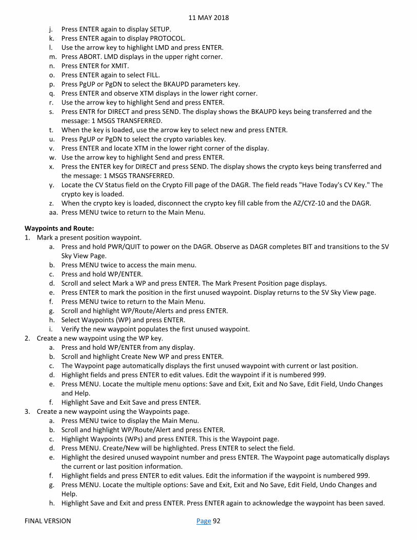
11 MAY 2018
FINAL VERSION Page 92
j. Press ENTER again to display SETUP. k. Press ENTER again to display PROTOCOL. l. Use the arrow key to highlight LMD and press ENTER. m. Press ABORT. LMD displays in the upper right corner. n. Press ENTER for XMIT. o. Press ENTER again to select FILL. p. Press PgUP or PgDN to select the BKAUPD parameters key. q. Press ENTER and observe XTM displays in the lower right corner. r. Use the arrow key to highlight Send and press ENTER. s. Press ENTR for DIRECT and press SEND. The display shows the BKAUPD keys being transferred and the
message: 1 MSGS TRANSFERRED. t. When the key is loaded, use the arrow key to select new and press ENTER. u. Press PgUP or PgDN to select the crypto variables key. v. Press ENTER and locate XTM in the lower right corner of the display. w. Use the arrow key to highlight Send and press ENTER. x. Press the ENTER key for DIRECT and press SEND. The display shows the crypto keys being transferred and
the message: 1 MSGS TRANSFERRED. y. Locate the CV Status field on the Crypto Fill page of the DAGR. The field reads "Have Today's CV Key." The
crypto key is loaded. z. When the crypto key is loaded, disconnect the crypto key fill cable from the AZ/CYZ-10 and the DAGR. aa. Press MENU twice to return to the Main Menu.
Waypoints and Route: 1. Mark a present position waypoint.
a. Press and hold PWR/QUIT to power on the DAGR. Observe as DAGR completes BIT and transitions to the SV Sky View Page.
b. Press MENU twice to access the main menu. c. Press and hold WP/ENTER. d. Scroll and select Mark a WP and press ENTER. The Mark Present Position page displays. e. Press ENTER to mark the position in the first unused waypoint. Display returns to the SV Sky View page. f. Press MENU twice to return to the Main Menu. g. Scroll and highlight WP/Route/Alerts and press ENTER. h. Select Waypoints (WP) and press ENTER. i. Verify the new waypoint populates the first unused waypoint.
2. Create a new waypoint using the WP key. a. Press and hold WP/ENTER from any display. b. Scroll and highlight Create New WP and press ENTER. c. The Waypoint page automatically displays the first unused waypoint with current or last position. d. Highlight fields and press ENTER to edit values. Edit the waypoint if it is numbered 999. e. Press MENU. Locate the multiple menu options: Save and Exit, Exit and No Save, Edit Field, Undo Changes
and Help. f. Highlight Save and Exit Save and press ENTER.
3. Create a new waypoint using the Waypoints page. a. Press MENU twice to display the Main Menu. b. Scroll and highlight WP/Route/Alert and press ENTER. c. Highlight Waypoints (WPs) and press ENTER. This is the Waypoint page. d. Press MENU. Create/New will be highlighted. Press ENTER to select the field. e. Highlight the desired unused waypoint number and press ENTER. The Waypoint page automatically displays
the current or last position information. f. Highlight fields and press ENTER to edit values. Edit the information if the waypoint is numbered 999. g. Press MENU. Locate the multiple options: Save and Exit, Exit and No Save, Edit Field, Undo Changes and
Help. h. Highlight Save and Exit and press ENTER. Press ENTER again to acknowledge the waypoint has been saved.
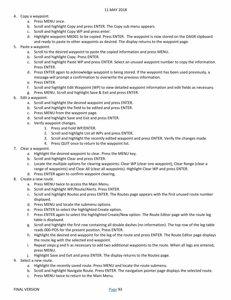
11 MAY 2018
FINAL VERSION Page 93
4. Copy a waypoint. a. Press MENU once. b. Scroll and highlight Copy and press ENTER. The Copy sub menu appears. c. Scroll and highlight Copy WP and press enter. d. Highlight waypoint MK001 to be copied. Press ENTER. The waypoint is now stored on the DAGR clipboard
and ready to paste to other waypoints as desired. The display returns to the waypoint page. 5. Paste a waypoint.
a. Scroll to the desired waypoint to paste the copied information and press MENU. b. Scroll and highlight Copy. Press ENTER. c. Scroll and highlight Paste WP and press ENTER. Select an unused waypoint number to copy the information.
Press ENTER. d. Press ENTER again to acknowledge waypoint is being stored. If the waypoint has been used previously, a
message will prompt a confirmation to overwrite the previous information. e. Press ENTER. f. Scroll and highlight Edit Waypoint (WP) to view detailed waypoint information and edit fields as necessary. g. Press MENU. Scroll and highlight Save & Exit and press ENTER.
6. Edit a waypoint. a. Scroll and highlight the desired waypoint and press ENTER. b. Scroll and highlight the field to be edited and press ENTER. c. Press MENU from the waypoint page. d. Scroll and highlight Save and Exit and press ENTER. e. Verify waypoint changes.
1. Press and hold WP/ENTER. 2. Scroll and highlight List all WPs and press ENTER. 3. Scroll and highlight the recently edited waypoint and press ENTER. Verify the changes made. 4. Press QUIT once to return to the waypoint list.
7. Clear a waypoint. a. Highlight the desired waypoint to clear. Press the MENU key. b. Scroll and highlight Clear and press ENTER. c. Locate the multiple options for clearing waypoints: Clear WP (clear one waypoint), Clear Range (clear a
range of waypoints) and Clear All (clear all waypoints). Highlight Clear WP and press ENTER. d. Press ENTER again to confirm waypoint clearing.
8. Create a new route. a. Press MENU twice to access the Main Menu. b. Scroll and highlight WP/Route/Alerts. Press ENTER. c. Scroll and highlight Routes and press ENTER. The Routes page appears with the first unused route number
displayed. d. Press MENU and locate the submenu options. e. Press ENTER to select the highlighted Create option. f. Press ENTER again to select the highlighted Create/New option. The Route Editor page with the route leg
table is displayed. g. Scroll and highlight the first row containing all double dashes (no information). The top row of the leg table
reads 000-POS for the present position. Press ENTER. h. Highlight the desired end waypoint for the leg of the route and press ENTER. The Route Editor page displays
the route leg with the selected end waypoint. i. Repeat steps g and h as necessary to add two additional waypoints to the route. When all legs are entered,
press MENU. j. Highlight Save and Exit and press ENTER. The display returns to the Routes page.
9. Select a new route. a. Highlight the recently saved route. Press MENU and locate the route submenu. b. Scroll and highlight Navigate Route. Press ENTER. The navigation pointer page displays the selected route. c. Press MENU twice to return to the Main Menu.

11 MAY 2018
FINAL VERSION Page 94
Operate When Signals are Weak: 1. Place DAGR in Average mode when signals are weak or lost.
a. From the Main Menu, use the up and down arrow keys to scroll and highlight Satellites and press ENTER. b. Highlight Satellite Vehicle (SV) Sky View and press ENTER. c. Once SV Sky View page displays, press MENU to access submenu. d. Highlight Select Op Mode and press ENTER. e. Highlight Average and press ENTER. f. Press ENTER to acknowledge note which warns against moving DAGR while in average mode.
2. Exit Average mode. a. Press MENU once conditions have improved and satellite signals are no longer obstructed. b. Highlight Select Op mode and press ENTER. c. Highlight Standby and press ENTER. d. Press MENU. e. Highlight Select Op mode and press ENTER. f. Highlight Fix and press ENTER. g. Verify DAGR performs a direct Y-code acquisition of at least 3 satellites. h. Press MENU twice to return to Main Menu.

11 MAY 2018
FINAL VERSION Page 95
P5: Camouflage and Visual Signaling Techniques Based on: 052-COM-1361-Camouflage Yourself and Your Individual Equipment 071-COM-0608-Use Visual Signaling Techniques
Task: Subtly employ realistic camouflage that resembles the background to your skin, uniform, weapon, and equipment. Demonstrate visual signaling techniques.
Condition: You are a member of a squad or team preparing to establish an ambush position in a non-CBRNE environment. You are in the patrol base preparing to move to the Objective Rally Point. Enemy presence is suspected.
Standard: Correctly apply camouflage within 10 minutes or less. Correctly demonstrate each of the 15 visual signaling techniques within 10 seconds of receiving the prompt.
Requirements: Both appropriate and inappropriate camouflage items based on the environment and the Candidate’s uniform/packing list. The training area should contain a mannequin or an actual Soldier who is completely camouflaged correctly and appropriately. The color charts and other graphic references from the appropriate references must also be available in the training area. The Candidate must know how to apply camouflage correctly, what the standard is for their environment/equipment, and be given the means/materials to succeed. The Unit will choose which 15 visual signaling techniques are to be used, and they must be the same 15 that were used during practice week.
Camouflage: 1. Employ realistic camouflage.
a. Employ camouflage material that resembles the background. b. Employ camouflage subtly without overdoing.
2. Breakup regular shapes. a. Use natural or artificial materials to breakup shapes, outlines, and equipment. b. Disguise or distort the shape of your helmet and your body with natural or artificial materials when
conducting operations close to the enemy. 3. Reduce possible shine by covering or removing items that may reflect light. 4. Blend colors with the surroundings, or at a minimum, ensure that objects do not contrast with the background. 5. Camouflage your exposed skin.
a. Cover your skin oils, using paint sticks, even if you have very dark skin. Note: Do not use oils or insect repellant to soften paint sticks. This defeats the purpose of paint sticks by making the skin shiny. Do not use mud, paint containing motor oil, or other field expedient paints for EIB.
b. Use the color chart when applying paint on the face. c. Paint high, shiny areas (forehead, cheekbones, nose, ears, and chin) with a dark color. d. Paint low, shadow areas (around the eyes, under the nose and under the chin) with a light color. e. Paint exposed skin on the back of the neck, arms, and hands with an irregular pattern.
6. Camouflage your uniform and helmet. a. Roll your sleeves down, and fasten all buttons/zippers/Velcro. b. Attach leaves, grass, small branches, or other items to your uniform and helmet that will distort shapes and
blend colors with the natural background. Note: Soldiers must be aware of local foliage hazards and possible reactions to poisonous leaves.
c. Wear unstarched uniforms. d. Do not wear excessively faded or worn uniforms because camouflage effectiveness is lost.
7. Camouflage your personal equipment. a. Cover or remove shiny items. b. Secure items that rattle or make noise when moved or worn. c. Breakup the shape of large and bulky equipment using natural or man-made items.
Visual Signaling Techniques: 1. Combat formations.
a. Disperse. 1. Extend the arm horizontally.

11 MAY 2018
FINAL VERSION Page 96
2. Wave the arm and hand to the front, left, right, and rear. 3. Point toward the direction of each movement.
b. Assemble or rally. 1. Raise arm vertically overhead. 2. Turn palm to the front. 3. Wave in large horizontal circles. 4. Point to assembly or rally site.
c. Join me, follow me, or come forward. 1. Point toward person(s) or unit. 2. Beckon by holding the arm horizontally to the front with palm up. 3. Motion toward the body.
d. Increase speed, double time, or rush. 1. Raise the fist to the shoulder. 2. Thrust the fist upward to the full extent of the arm and back to shoulder level. 3. Continue rapidly several times.
e. Quick time. 1. Extend the arm horizontally sideward. 2. Turn palm to the front. 3. Wave the arm slightly downward several times, keeping the arm straight. 4. Keep arm at shoulder level.
f. Enemy in sight. 1. Hold the rifle in the ready position at shoulder level. 2. Point the rifle in the direction of the enemy.
g. Wedge. 1. Extend the arms downward to the side. 2. Turn the palms to the front. 3. Place your arms at a 45-degree angle below horizontal.
h. Vee. 1. Raise the arms. 2. Extend the arms 45-degrees above the horizontal.
i. Line. 1. Extend the arms. 2. Turn palms downward parallel to the ground.
j. Coil. 1. Raise one arm above the head. 2. Rotate it in a small circle.
k. Staggered column. 1. Extend the arms so that upper arms are parallel to the ground. 2. Make sure the forearms are perpendicular. 3. Raise the arms so they are fully extended above the head.
2. Battle drills. a. Contact left or right. Grader choice.
1. Extend the left/right arm parallel to the ground. 2. Bend the arm until the forearm is perpendicular. 3. Repeat.
b. Action left or right. Grader choice. 1. Extend both arms parallel to the ground. 2. Raise the right arm until it is overhead. 3. Repeat.
c. Air attack. 1. Bend the arms with forearms at a 45-degree angle. 2. The forearms should cross. 3. Repeat.

11 MAY 2018
FINAL VERSION Page 97
d. Nuclear, biological, or chemical attack. 1. Extend the arms and fists. 2. Bend the arms to the shoulders. 3. Repeat.
3. Patrolling. a. Map check.
1. Place one hand on top of the other. 2. Point at the palm of one hand with the index finger of the other hand.
b. Pace count. 1. Bend the knee so that the heel can be tapped on. 2. Tap the heel of the boot repeatedly with the open hand.
c. Head count. 1. Raise one arm behind the head. 2. Tap the back of the helmet repeatedly with an open hand.
d. Danger area. 1. Raise the right hand up until it is level with the throat. 2. Draw the right hand, palm down in a throat-cutting motion from left to right across the neck.
e. Freeze or halt. 1. Make a fist with the right hand. 2. Raise the fist to head level.
4. Control drivers. a. Start engine or prepare to move.
1. Simulate cranking of the engine by moving the arm, with the fist, in a circular motion at waist level.
b. Halt or stop. 1. Raise the hand upward to the full extent of the arm, with palm to the front. 2. Hold that position until the signal is understood.
c. Left or right turn. Grader choice. 1. Extend the opposite arm horizontally to the side. 2. Turn palm toward vehicle with finger extended in the direction of travel.
d. Move forward. 1. Face the vehicle. 2. Raise the hands to shoulder level with palms facing the chest. 3. Move the hands and forearms backward and forward.
e. Move in reverse. 1. Face the vehicle. 2. Raise the hands to shoulder level with palms facing the vehicle. 3. Move the hands and forearms backward and forward.
f. Stop engine. 1. Extend the arm parallel to the ground with hand open. 2. Move the arm across the body in a throat-cutting motion.
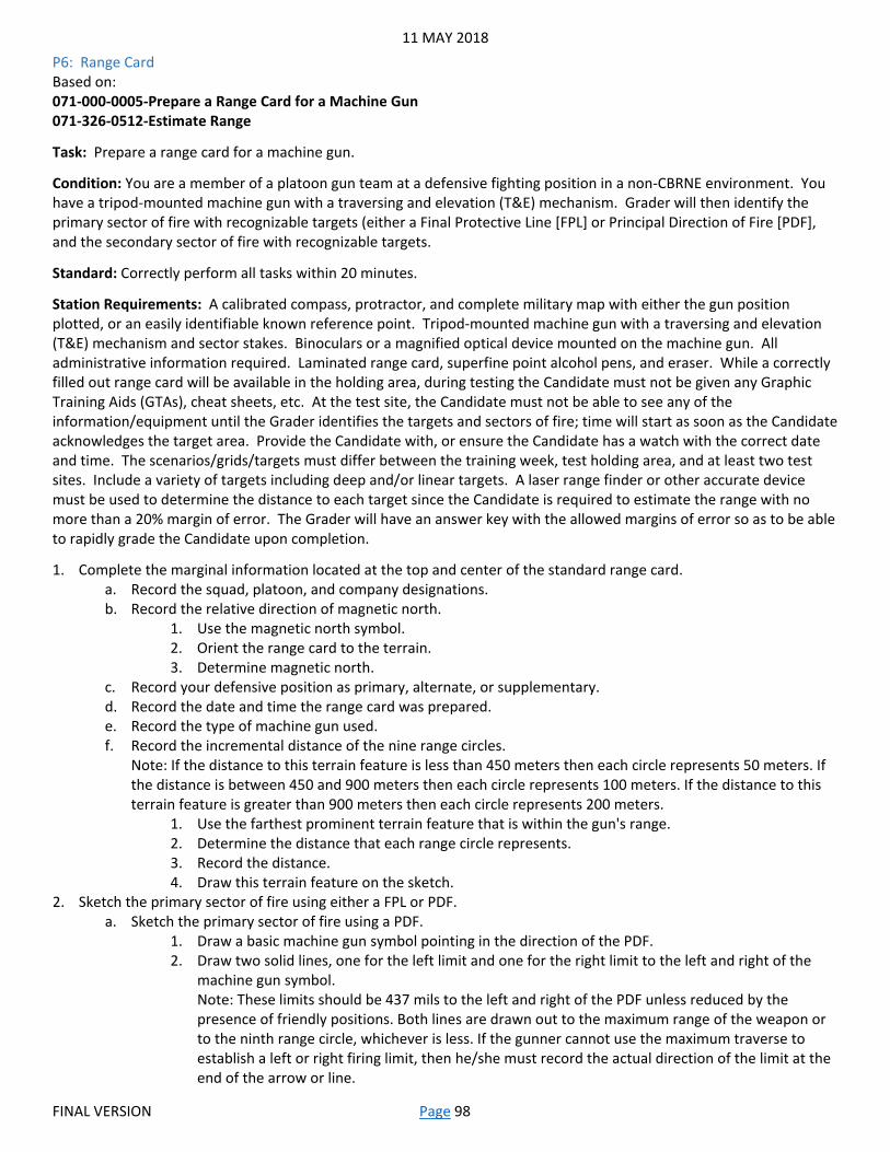
11 MAY 2018
FINAL VERSION Page 98
P6: Range Card Based on: 071-000-0005-Prepare a Range Card for a Machine Gun 071-326-0512-Estimate Range
Task: Prepare a range card for a machine gun.
Condition: You are a member of a platoon gun team at a defensive fighting position in a non-CBRNE environment. You have a tripod-mounted machine gun with a traversing and elevation (T&E) mechanism. Grader will then identify the primary sector of fire with recognizable targets (either a Final Protective Line [FPL] or Principal Direction of Fire [PDF], and the secondary sector of fire with recognizable targets.
Standard: Correctly perform all tasks within 20 minutes.
Station Requirements: A calibrated compass, protractor, and complete military map with either the gun position plotted, or an easily identifiable known reference point. Tripod-mounted machine gun with a traversing and elevation (T&E) mechanism and sector stakes. Binoculars or a magnified optical device mounted on the machine gun. All administrative information required. Laminated range card, superfine point alcohol pens, and eraser. While a correctly filled out range card will be available in the holding area, during testing the Candidate must not be given any Graphic Training Aids (GTAs), cheat sheets, etc. At the test site, the Candidate must not be able to see any of the information/equipment until the Grader identifies the targets and sectors of fire; time will start as soon as the Candidate acknowledges the target area. Provide the Candidate with, or ensure the Candidate has a watch with the correct date and time. The scenarios/grids/targets must differ between the training week, test holding area, and at least two test sites. Include a variety of targets including deep and/or linear targets. A laser range finder or other accurate device must be used to determine the distance to each target since the Candidate is required to estimate the range with no more than a 20% margin of error. The Grader will have an answer key with the allowed margins of error so as to be able to rapidly grade the Candidate upon completion.
1. Complete the marginal information located at the top and center of the standard range card. a. Record the squad, platoon, and company designations. b. Record the relative direction of magnetic north.
1. Use the magnetic north symbol. 2. Orient the range card to the terrain. 3. Determine magnetic north.
c. Record your defensive position as primary, alternate, or supplementary. d. Record the date and time the range card was prepared. e. Record the type of machine gun used. f. Record the incremental distance of the nine range circles.
Note: If the distance to this terrain feature is less than 450 meters then each circle represents 50 meters. If the distance is between 450 and 900 meters then each circle represents 100 meters. If the distance to this terrain feature is greater than 900 meters then each circle represents 200 meters.
1. Use the farthest prominent terrain feature that is within the gun's range. 2. Determine the distance that each range circle represents. 3. Record the distance. 4. Draw this terrain feature on the sketch.
2. Sketch the primary sector of fire using either a FPL or PDF. a. Sketch the primary sector of fire using a PDF.
1. Draw a basic machine gun symbol pointing in the direction of the PDF. 2. Draw two solid lines, one for the left limit and one for the right limit to the left and right of the
machine gun symbol. Note: These limits should be 437 mils to the left and right of the PDF unless reduced by the presence of friendly positions. Both lines are drawn out to the maximum range of the weapon or to the ninth range circle, whichever is less. If the gunner cannot use the maximum traverse to establish a left or right firing limit, then he/she must record the actual direction of the limit at the end of the arrow or line.
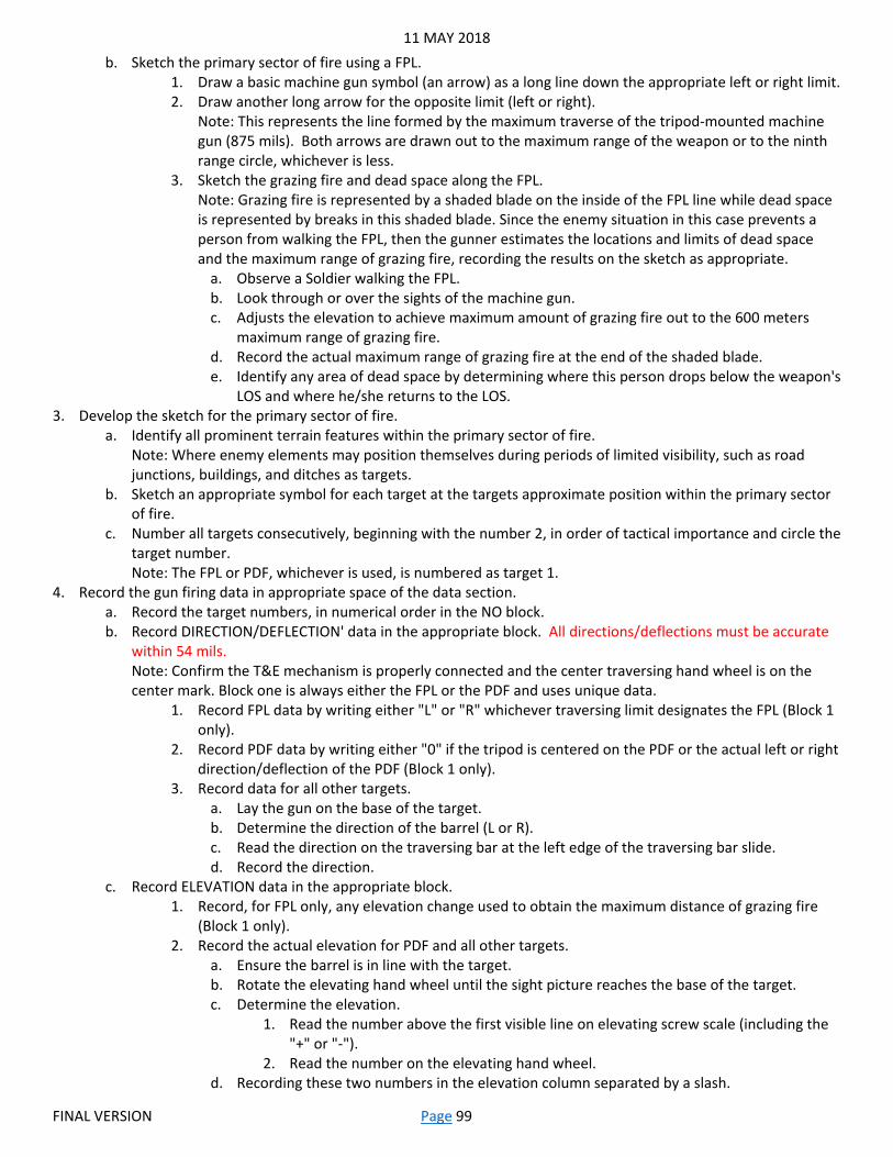
11 MAY 2018
FINAL VERSION Page 99
b. Sketch the primary sector of fire using a FPL. 1. Draw a basic machine gun symbol (an arrow) as a long line down the appropriate left or right limit. 2. Draw another long arrow for the opposite limit (left or right).
Note: This represents the line formed by the maximum traverse of the tripod-mounted machine gun (875 mils). Both arrows are drawn out to the maximum range of the weapon or to the ninth range circle, whichever is less.
3. Sketch the grazing fire and dead space along the FPL. Note: Grazing fire is represented by a shaded blade on the inside of the FPL line while dead space is represented by breaks in this shaded blade. Since the enemy situation in this case prevents a person from walking the FPL, then the gunner estimates the locations and limits of dead space and the maximum range of grazing fire, recording the results on the sketch as appropriate.
a. Observe a Soldier walking the FPL. b. Look through or over the sights of the machine gun. c. Adjusts the elevation to achieve maximum amount of grazing fire out to the 600 meters
maximum range of grazing fire. d. Record the actual maximum range of grazing fire at the end of the shaded blade. e. Identify any area of dead space by determining where this person drops below the weapon's
LOS and where he/she returns to the LOS. 3. Develop the sketch for the primary sector of fire.
a. Identify all prominent terrain features within the primary sector of fire. Note: Where enemy elements may position themselves during periods of limited visibility, such as road junctions, buildings, and ditches as targets.
b. Sketch an appropriate symbol for each target at the targets approximate position within the primary sector of fire.
c. Number all targets consecutively, beginning with the number 2, in order of tactical importance and circle the target number. Note: The FPL or PDF, whichever is used, is numbered as target 1.
4. Record the gun firing data in appropriate space of the data section. a. Record the target numbers, in numerical order in the NO block. b. Record DIRECTION/DEFLECTION' data in the appropriate block. All directions/deflections must be accurate
within 54 mils. Note: Confirm the T&E mechanism is properly connected and the center traversing hand wheel is on the center mark. Block one is always either the FPL or the PDF and uses unique data.
1. Record FPL data by writing either "L" or "R" whichever traversing limit designates the FPL (Block 1 only).
2. Record PDF data by writing either "0" if the tripod is centered on the PDF or the actual left or right direction/deflection of the PDF (Block 1 only).
3. Record data for all other targets. a. Lay the gun on the base of the target. b. Determine the direction of the barrel (L or R). c. Read the direction on the traversing bar at the left edge of the traversing bar slide. d. Record the direction.
c. Record ELEVATION data in the appropriate block. 1. Record, for FPL only, any elevation change used to obtain the maximum distance of grazing fire
(Block 1 only). 2. Record the actual elevation for PDF and all other targets.
a. Ensure the barrel is in line with the target. b. Rotate the elevating hand wheel until the sight picture reaches the base of the target. c. Determine the elevation.
1. Read the number above the first visible line on elevating screw scale (including the "+" or "-").
2. Read the number on the elevating hand wheel. d. Recording these two numbers in the elevation column separated by a slash.

11 MAY 2018
FINAL VERSION Page 100
d. Record the RANGE data, in meters, in the appropriate block. All ranges must be accurate within 20%. 1. Record for a FPL, the maximum achieved distance of grazing fire. 2. Record for the PDF and all other targets the distance to the target.
e. Record any special ammunition required in the AMMO block. If used, this will be given by the Grader in the instruction brief.
f. Describe the target in the block labeled DESCRIPTION. 1. Record a FPL as "FPL". 2. Record a PDF as "PDF". 3. Describe all other targets by providing a simple description of the target.
g. Record REMARKS in the appropriate block. 1. Record the elevation change, for the FPL only that causes the rounds to strike the ground at the
beginning of the first dead space. 2. Record data for Large (Deep) targets that defines the target's depth.
a. Lay the weapon on target. b. Record target number.
1. Write and circle the target number in the remarks section. 2. Write the letters "TD" (target depth). 3. Write the already determined elevation and the word "to".
c. Rotate the elevating hand wheel until the sight picture reaches the top of the target. d. Determine the depth.
Note: This is a second elevation reading, which can be done by reading the number above the first visible line on elevating screw scale (including the "+" or "-") and then reading the number on the elevating hand wheel.
e. Record these two numbers after the "to". Note: Example TD +50/15 to +50/22.
3. Record data for Linear targets that defines the target's width. a. Record target number.
1. Write and circle the target number in the remarks section. 2. Write the letters "TW" (target width) followed by some blank space and then a
slash. b. Lay the gun on the target using existing data.
Note: The initial target data should lay the gun on the most dangerous point of the target, which may be anywhere on the target.
c. Traverse from this initial lay point, to the most dangerous edge of the target. 1. Count the number of MILS. 2. Note the direction (L or R) of movement.
d. Record this data to the right of the slash. Accurate within 54 mils. e. Traverse the gun to the opposite edge of the target counting the total number of MILS. f. Record this data to the left of the slash. Accurate within 54 mils.
Note: Example TW 15 / L8. 5. Sketch the secondary sector of fire.
a. Draw a "V" using two broken lines to represent the left and right limits of the secondary sector of fire. b. Sketch identified targets in the secondary sector of fire. c. Record the range (in meters) to each target above the target's sketch. All ranges must be accurate within
20%. d. Employ field expedient firing aids for the secondary sector. e. Sketch the field expedient firing aid above the target for ease of identification.
Note: Firing data is not determined for the secondary sector of fire as the tripod remains fixed in the primary firing position. To fire in the secondary sector of fire, the gun is dismounted from the tripod, moved, and fired in the bipod mode. The gunner uses field expedient firing aids for targets in the secondary sector.
6. Label the area between the primary and secondary sectors as dead space. 7. Record the position of the machine gun.
a. Use the Grid Method.

11 MAY 2018
FINAL VERSION Page 101
1. Determine the eight-digit grid coordinate of the gun. 2. Record the coordinate directly below the gun position.
b. Use the Reference Point Method. 1. Orient the firing position to a prominent terrain feature (recognizable on a map) no more than
1000 meters away. 2. Draw a line between these two points, with barbed arrows pointing to the gun position. 3. Determine the azimuth from the terrain feature to the gun position. 4. Record the azimuth in mils or degrees below the barbed line. Accurate within three degrees or 54
mils. 5. Determine the distance from the terrain feature to the gun position and recording above the
barbed line.

11 MAY 2018
FINAL VERSION Page 102
P7: Chemical and Biological Operations Based on: 031-COM-1004-Protect Yourself from Chemical and Biological (CB) Contamination Using Your Assigned Protective Mask 031-COM-1006-Decontaminate your Skin 031-COM-1011-Decontaminate Individual Equipment
Task: Assume Mission Oriented Protective Posture (MOPP) level three. Decontaminate your skin and equipment, assuming MOPP level four.
Condition: You are a member of a platoon within a secure Forward Operating Base (FOB). You are in MOPP level two when you suspect a chemical/biological attack.
Standard: Don, clear, and seal the mask within nine seconds and perform all remaining tasks to standard, in sequence, within one minute. Correctly decontaminate and assume MOPP level four within five minutes.
Station Requirements: Candidate’s own functional, properly maintained mask with mask hood if the hood is not integrated in the joint-service lightweight integrated suit technology (JSLIST). Properly fitted JSLIST coat, trousers, over-boots, and gloves for the Candidate to wear. Training decontamination kits or simulated materials. Poncho or overhead cover.
Assume MOPP Level Three: 1. Don mask assembly.
a. Stop Breathing and close eyes. b. Remove helmet, put helmet between legs above knees or hold rifle between legs and place helmet on the
muzzle. Note: If helmet falls continue to mask.
c. Take off glasses and place in helmet, if applicable. d. Open the mask carrier with non-firing hand. e. Grasp the mask assembly with firing hand and remove it from the carrier. f. Place chin in the chin pocket and press the face piece tight against face. g. Hold mask assembly tightly against face. h. Grasp the harness tab, pull the harness over and down the head as far as possible.
Note: Ensure the head harness is centered on the crown of the head and the temple straps are approximately parallel to the ground.
i. Grasp the loose end of the cheek straps, one at a time, and pull until strap feels tight. Note: Both straps should be approximately equal length when complete. The temple and forehead straps have already been adjusted during fitting; do not tighten.
2. Clear mask assembly. a. Seal the outlet disk valve by placing one hand over the outlet valve cover assembly. b. Blow out hard to ensure that any contaminated air is forced out around the edges of the face piece.
3. Seal mask assembly. a. Cover both filter inlet ports with the palms of your hands and breathe in. b. Ensure mask assembly collapse against the face. c. Resume breathing.
4. Give the alarm. a. Shout, "Gas, Gas, Gas." b. Give the appropriate hand-and-arm signal per unit SOP.
5. Close mask carrier. 6. Don the mask hood, if applicable.
Note: If the Soldier is using the mask in conjunction with the joint-service, lightweight integrated suit technology (JSLIST), he/she skips this step (the mask lacks a hood because it is built in on the JSLIST). Be careful when pulling on the hood because it could snag and tear on the buckles of the head harness. Be careful not to break face piece seal when pulling protective hood over your head.
a. Place hands up under the protective hood, stretch elasticized portion and raise protective hood up and over

11 MAY 2018
FINAL VERSION Page 103
filters. b. Carefully pull excess protective hood material over head, neck and shoulders. c. Grasp underarm straps. d. Bring the male end of each underarm strap and fasten to female end. e. Leave underarm straps loose enough to allow decontamination.
Assume MOPP Level Four: 1. Seek overhead cover or use a poncho for protection against further contamination. 2. Decontaminate your hands, face, and the inside of your mask.
a. Remove one RSDL packet from your carrying pouch. Safety: Avoid contact with eyes and wounds. If contact with eyes or wounds occurs, rinse with water as soon as possible.
b. Tear it open quickly at any notch. c. Remove the applicator pad from the packet, and save the packet as the remaining lotion can be added to
the applicator pad, if required. d. Thoroughly scrub the exposed skin of your hand, palm, and fingers with the applicator pad.
Note: The applicator pad can be used from either side and may be gripped in any manner allowing the applicator pad to be applied to the skin.
e. Switch the applicator pad to the other hand, and repeat the procedure. f. Stop breathing, close eyes, grasp mask beneath chin and pull mask away from chin enough to allow one
hand between the mask and your face. Hold the mask in this position. g. Thoroughly scrub the exposed skin of your face with lotion from the applicator pad. h. Thoroughly scrub across your forehead. i. Beginning at one side, scrub up and down across your cheeks, nose, chin, and closed mouth. Avoid ingesting. j. Scrub under the chin from the ear along the jawbone to the other ear to coat your skin with lotion. k. Turn your hand over and scrub the inside surfaces of the mask that may touch your skin. Be sure to include
the drinking tube. Note: Do not apply lotion to the lens of the protective mask. The RSDL may cause loss of transparency.
l. Keep the applicator. m. Seal your mask immediately, clear it, and check it. n. Use the applicator and any remaining lotion in the packet. Without breaking the mask seal, scrub the
applicator pad across the forehead, exposed scalp, the skin of the neck, ears, and throat. o. Secure the hood and tighten the straps. p. Thoroughly scrub your hands with lotion again as in the steps above. q. Assume MOPP Level 4 by putting on protective gloves.
3. Decontaminate your equipment. a. Open the M334 at either end where the Kit is notched. b. Remove one M334 packet from the kit. c. Open an M334 packet at a notch on the packet. d. Remove the individual wipe from the packet and unfold completely. e. Decontaminate all contaminated individual equipment by wiping the surface using sweeping motions away
from the body. Take care not to spread any contamination to any area that has been visually determined as clean. Note: M334 individual wipe may leave behind a film on decontaminated surfaces. This film may alter how certain surfaces (i.e. optics, reflective surfaces) process light. Refer to the decontaminated equipment's TM for cleaning procedures, as some surfaces may require specific procedures to avoid damaging the surface. In the absence of cleaning procedures, a lens cloth has been found to be an effective means of removing any film left behind by the M334 individual wipe. Note: The wipe may be folded/refolded as necessary to maximize use of the clean areas of the wipe, to obtain the proper grip, and to ensure even contact pressure. When wiping, pay special attention to areas that are hard to reach, such as cracks, crevices, and absorbent materials. To avoid premature evaporation of the solvent, do not open a new M334 packet until needed.
f. Dispose of contaminated waste material IAW unit SOP and local and federal regulations.

11 MAY 2018
FINAL VERSION Page 104
P8: Resection and Military Maps Based on: 071-COM-1015-Locate an Unknown Point on a Map and on the Ground by Resection 071-COM-1000-Identify Topographic Symbols on a Military Map 071-COM-1001-Identify Terrain Features on a Map
Task: Determine your location. Identify terrain features and colors. Identify topographic symbols.
Condition: You are a member of a squad or team conducting tactical operations and have a requirement to determine your current location.
Standard: Determine the correct six digit grid to your location using resection within five minutes. Identify five major, three minor, and two supplementary terrain features and what the six basic colors represent within five minutes with 100% accuracy. Identify at least 20 out of 22 topographic symbols within ten minutes with no incorrect answers.
Station Requirements: A protractor, straight edge, calibrated compass, and military map(s) (use as many maps as required to ensure all terrain features are represented). Laminated paper with 39 blank lines labeled appropriately (one for Candidate’s grid, five for the major terrain features, three for the minor terrain features, two for the supplementary terrain features, six for the colors, and 22 for the topographic symbols), alcohol pens, and eraser. The map for resection must have two clearly identifiable features that are visible to the Candidate. If the local terrain is limited, E-Type targets, vehicles, etc. may be used as long as they are clearly plotted and labeled on the map. The map(s) for identifying symbols and features must have each item to be identified clearly labeled. The training area will have the figures and illustrations from the ATN tasks, as well as any additional references. While all the information will be available in the holding area, during testing the Candidate must not be given any Graphic Training Aids (GTAs), cheat sheets, etc. At the test site, the Candidate must not be able to see any of the information/equipment until time has started. The maps/grids/features must differ between the training week, test holding area, and at least two test sites.
Resection: 1. Identify your location on a map by resection using the map and compass method.
a. Orient the map on a flat surface using a compass. b. Identify at least two well-defined points on the ground. c. Mark these well-defined points on the map. d. Plot the back azimuths of these points on the map.
1. Determine the magnetic azimuth from your location to one of the defined points. 2. Convert the magnetic azimuth to a grid azimuth. 3. Convert this grid azimuth to a back grid azimuth. 4. Place the index point of a protractor on the well-defined point. 5. Align the protractor's 0- to 180-degree line to the top of the map's North-South grid line. 6. Ensure the 0-degree mark is pointing to the north (or top of map). 7. Place a tick mark on the map beside the number on the protractor that corresponds to the
computed back grid azimuth. 8. Draw a straight line from the well-defined point to the tick and beyond. 9. Repeat for each well-defined point.
e. Identify the point where the lines intersect as your location. f. Determine the six digit grid coordinates to this location.
2. Identify your location on a map by resection using the straightedge method. a. Orient your map on a flat surface using terrain association. b. Locate at least two known distant locations or prominent features on the ground. c. Plot these distant locations or prominent features on the map. d. Draw a resection line for each of these plotted points.
1. Lay a straightedge on one of the two known points on the map. 2. Rotate the straightedge on the map until straight edge lines up with both the known position on
the map and the known position in the distance. 3. Draw a line along the straightedge away from the known position on the ground toward your
position.

11 MAY 2018
FINAL VERSION Page 105
4. Repeat for each plotted point. e. Identify the point where the lines intersect as your location. f. Determine the six digit grid coordinates to this location.
Identify Terrain Features and Colors: 1. Major terrain features.
a. Hill. Note: A hill is an area of high ground. From a hilltop, the ground slopes down in all directions. A hill is shown on a map by contour lines forming concentric circles. The inside of the smallest closed circle is the hilltop.
b. Saddle. Note: A saddle is a dip or low point between two areas of higher ground. A saddle is not necessarily the lower ground between two hilltops; it may be simply a dip or break along a level ridge crest. If you are in a saddle, there is high ground in two opposite directions and lower ground in the other two directions. A saddle is normally represented as an hourglass.
c. Valley. Note: A valley is a stretched-out groove in the land, usually formed by streams or rivers. A valley begins with high ground on three sides and usually has a course of running water through it. If standing in a valley, three directions offer high ground, while the fourth direction offers low ground. Depending on its size and where a person is standing, it may not be obvious that there is high ground in the third direction, but water flows from higher to lower ground. Contour lines forming a valley are either U-shaped or V-shaped. To determine the direction water is flowing, look at the contour lines. The closed end of the contour line (U or V) always points upstream or toward high ground.
d. Ridge. Note: A ridge is a sloping line of high ground. If you are standing on the centerline of a ridge, you will normally have low ground in three directions and high ground in one direction with varying degrees of slope. If you cross a ridge at right angles, you will climb steeply to the crest and then descend steeply to the base. When you move along the path of the ridge, depending on the geographic location, there may be either an almost unnoticeable slope or a very obvious incline. Contour lines forming a ridge tend to be U-shaped or V-shaped. The closed end of the contour line points away from high ground.
e. Depression. Note: A depression is a low point in the ground or a sinkhole. It could be described as an area of low ground surrounded by higher ground in all directions, or simply a hole in the ground. Usually only depressions that are equal to or greater than the contour interval will be shown. On maps, depressions are represented by closed contour lines that have tick marks pointing toward low ground.
2. Minor terrain features. a. Draw.
Note: A draw is a stream course that is less developed than a valley. In a draw, there is essentially no level ground and, therefore, little or no maneuver room within its confines. If you are standing in a draw, the ground slopes upward in three directions and downward in the other direction. A draw could be considered as the initial formation of a valley. The contour lines depicting a draw are U-shaped or V-shaped, pointing toward high ground.
b. Spur. Note: A spur is a short, continuous sloping line of higher ground, normally jutting out from the side of a ridge. A spur is often formed by two roughly parallel streams cutting draws down the side of a ridge. The ground will slope down in three directions and up in one. Contour lines on a map depict a spur with the U or V pointing away from high ground.
c. Cliff. Note: A cliff is a vertical or near vertical feature; it is an abrupt change of the land. When a slope is so steep that the contour lines converge into one “carrying” contour of contours, this last contour line has tick marks pointing toward low ground. Cliffs are also shown by contour lines very close together and, in some instances, touching each other.
3. Supplementary terrain features. a. Cut.
11 MAY 2018
FINAL VERSION Page 106
Note: A cut is a man-made feature resulting from cutting through raised ground, usually to form a level bed for a road or railroad track. Cuts are shown on a map when they are at least 10 feet high, and they are drawn with a contour line along the cut line. This contour line extends the length of the cut and has tick marks that extend from the cut line to the roadbed, if the map scale permits this level of detail.
b. Fill. Note: A fill is a man-made feature resulting from filling a low area, usually to form a level bed for a road or railroad track. Fills are shown on a map when they are at least 10 feet high, and they are drawn with a contour line along the fill line. This contour line extends the length of the filled area and has tick marks that point toward lower ground. If the map scale permits, the length of the fill tick marks are drawn to scale and extend from the base line of the fill symbol.
4. Colors. a. Blue: Hydrography or water features such as lakes, swamps, rivers, and drainage. b. Black: Cultural (manmade) features such as buildings and roads, surveyed spot elevations, and all labels. c. Green: Vegetation with military significance such as woods, orchards, and vineyards. d. Brown: All relief features and elevation such as contours on older edition maps and cultivated land on red
light readable maps. e. Red: Cultural features, such as populated areas, main roads, and boundaries, on older maps. f. Red-brown: Cultural features, all relief features, non-surveyed spot elevations, and elevation such as
contour lines on red light readable maps.
Identify Topographic Symbols: 1. Identify the sheet name. 2. Identify the sheet number. 3. Identify the series name. 4. Identify the scale. 5. Identify the series number. 6. Identify the edition number. 7. Identify the index to boundaries. 8. Identify the adjoining sheets diagram. 9. Identify the elevation guide. 10. Identify the declination diagram. 11. Identify the bar scales. 12. Identify the contour interval note. 13. Identify the spheroid note. 14. Identify the grid note. 15. Identify the projection note. 16. Identify the vertical datum note. 17. Identify the horizontal datum note. 18. Identify the control note. 19. Identify the preparation note. 20. Identify the printing note. 21. Identify the grid reference box. 22. Identify the unit imprint and symbol.
11 MAY 2018
FINAL VERSION Page 107
P9: M18A1 Claymore Mine Based on: 071-325-4427-Employ an M18A1 Claymore Munition 071-325-4426-Recover an M18A1 Claymore Mine
Task: Employ a Claymore mine. Recover a Claymore mine.
Condition: You are a member of a platoon in a patrol base in a non-CBRNE environment. You have been directed to utilize a Claymore mine with an electrical initiator to enhance the perimeter defense. There is a known enemy presence.
Standard: Correctly employ a Claymore mine, in sequence, within ten minutes. Correctly recover a Claymore mine, in sequence, within five minutes.
Station Requirements: A training Claymore mine/munition with all basic items of inventory (BII). One wooden stake in the ground or a fixed object at the observation position, and one at the mine location. Sandbags, trees, or holes in the ground for Candidate to use to test the mine. A ground level target for the Candidate to aim at 50 meters in front of the mine emplacement location.
Emplace and Fire: 1. Inventory the M18A1 Claymore munition.
Note: For electrical initiation the munition components consist of the M57 firing device, M4 electric blasting cap assembly, the M40 test set and the M7 bandoleer.
2. Select a firing position. Note: The operator should select a firing position that offers cover and unobstructed observation of the site selected for emplacing the munition.
3. Prepare the munition for employment. a. Place the bandoleer on the shoulder or around the neck. b. Ensure that the munition and all accessories are in the M7 bandoleer. c. Conduct a circuit test.
1. Perform circuit test on the M57 firing device. a. Remove the M57 firing device and the M40 test set from the bandoleer. b. Remove the dust cover from the connector of the M57 firing device. c. Remove the dust cover from the female connector of the M40 test set. d. Plug the M40 test set into the M57 firing device. e. Move the firing device bail to the FIRE position. f. Depress the handle of the M57 firing device with a firm, quick squeeze, observing the flash
of light through the window of the test set. Note: The indicator lamp flashes if the firing device is functioning properly. When checking the firing device and blasting cap circuitry, the operator holds the window of the test set near their eye and shades it with their other hand. This minimizes the risk of enemy observation in the dark and enables the operator to see the indicator lamp flashing, even in bright sunlight. Corrosion on the electrical connectors of the test set can cause the indicator lamp to function improperly (not flash). The operator can overcome this by connecting and disconnecting the shorting plug dust cover on the M40 test set. If the test set indicates that several firing devices are faulty, he should retest with another set, since the device may be defective.
g. Move the firing device bail to the SAFE position. h. Place the firing device with the test set attached in the M7 bandoleer.
2. Perform circuit test of the M4 electrical blasting cap assembly. Note: The firing circuit test must be conducted before placing the blasting cap into the detonator well. Before and after completion of the firing device and blasting cap continuity tests, the operator must ensure that the safety bail is in the SAFE position.
a. Remove the M4 electrical blasting cap assembly from the bandoleer. b. Remove the twist tie from the spool. c. Starting at the shorting plug/dust cover end of the electrical wire, uncoil approximately 1
11 MAY 2018
FINAL VERSION Page 108
meter (3 feet) of wire. d. At the 1-meter mark, fold the firing wire to create a loop with a large enough circumference
to go around a stake or a fixed object at the firing position. e. Twist the wire loop over the index and middle fingers of the right hand. f. Push the loop through the circle created in the previous step. g. Secure the firing wire from the blasting cap side of the munition to a stake or a fixed object
at the firing position. h. Uncoil enough wire to place the spool out of sight. i. Place the remaining spool of wire (with the blasting cap inside the spool) under a sandbag,
behind a tree, or in a hole in the ground. j. Remove the M57 firing device with the M40 test set attached from the M7 bandoleer. k. Remove the shorting plug/dust cover from the connector of the firing wire. l. Remove the shorting plug/dust cover from the end of the test set. m. Plug the connector of the firing wire into the test set. n. Move the firing device safety bail to the FIRE position. o. Depress the handle of the firing device with a firm, quick squeeze, observing the flash of
light through the window of the test set. Note: When squeezing the handle of the firing device, an indicator lamp in the window of the test set flashes. This flash indicates that the blasting cap circuitry is satisfactory. If the lamp does not flash, the operator should notify a supervisor.
p. Move the firing device bail from the FIRE position to the SAFE position. q. Disconnect the test set from the firing wire. r. Replace the firing wire shorting plug/dust cover. s. Disconnect the test set from the firing device. t. Replace the firing device and test set dust covers. u. Repack the firing device and test set in the bandoleer.
d. Move tactically to the desired location where the munition will be setup. Note: The setup location should be no more than 30 meters from the firing position.
1. Remove the spool with the remaining firing wire and blasting cap from the protective barrier used during circuit testing of the electrical wire.
2. Unroll the firing wire from the firing position to the site selected for munition emplacement. 3. Lay the spool (with the blasting cap inside) down within arm’s reach of the munition emplacement
site. e. Assume a prone position. f. Remove the munition from the bandoleer. g. Open both pairs of legs to a 45 degree angle with two legs facing to the front and two legs facing to the rear
of the munition. h. Ensure that the face of the munition marked 'FRONT TOWARD ENEMY' and the arrows on the top of the
munition point in the direction of the enemy. i. Push the legs about one-third of the way into the ground with the munition facing in the desired direction of
fire. Note: In windy areas or when the legs cannot be pressed into the ground, the legs should be spread as far as they will go (about 180 degrees) so that the legs are to the front and rear of the mine and the mine will not tip over.
4. Aim the munition. a. Select an aiming point at ground level about 50 meters (150 feet) in front of the munition. b. Position one eye about six inches to the rear of the sight.
1. On a knife-edge sight, align the two edges of the sight with the aiming point. 2. On slit-type peep sight, align the groove of the sight in line with the aiming point that is 2.5 meters
(8 feet) off the ground. Note: The aiming point should be in the center of the desired area of coverage, with the bottom edge of the peep sight parallel to the ground that is to be covered with the fragment spray.
5. Arm the munition.
11 MAY 2018
FINAL VERSION Page 109
a. Remove the blasting cap from the spool’s cavity. b. Secure the firing wire about one meter to the rear of the munition, so the munition will remain aligned if the
firing wire is disturbed. c. Unscrew one of the shipping plug priming adapters from the munition. d. Slide the slotted end of the shipping plug priming adapter onto the firing wire of the blasting cap between
the crimped connections and the blasting cap. e. Pull the excess wire through the slotted end of the adapter until the top of the blasting cap is firmly seated
in the bottom portion of the shipping plug priming adapter. f. Screw the adapter, with the blasting cap, into the detonator well. g. Check the aim of the munition to ensure that the point of aim has not changed.
6. Camouflage the munition and firing wire on the way back to the firing position. 7. Fire the munition.
a. Seek cover. b. Remove the dust cover on the M57 firing device. c. Remove the shorting plug/dust cover from the end of the firing wire. d. Connect the M57 firing device to the firing wire. e. Move the M57 firing device safety bail to the FIRE position. f. Quickly squeeze the M57 firing device handle.
Recover: 1. Disarm the mine.
a. Ensure the M57 firing device safety bail is in the SAFE position. b. Disconnect the M57 firing device from the firing wire. c. Replace the shorting plug dust cover on the firing wire connector. d. Replace the dust cover on the M57 firing device connector. e. Place M57 firing device back in the M7 bandoleer. f. Untie the firing wire from the stake at the firing site. g. Move tactically to the mine. h. Remove the shipping plug priming adapter by unscrewing it from the blasting cap. i. Separate the shipping plug priming adapter and the blasting cap. j. Reverse the shipping plug. k. Screw the shipping plug end of the adapter into the detonator well. l. Remove the firing wire from the stake at the mine site. m. Place the blasting cap into the end of the wire connector. n. Roll the wire onto the wire container.
2. Secure the mine. a. Lift the mine from its emplacement. b. Secure the folding legs. c. Repack the mine and all the accessories into the M7 bandoleer.
11 MAY 2018
FINAL VERSION Page 110
P10: Transmit a Spot Report with a Tactical Satellite Radio Based on: 113-589-2004-Operate TACSAT Radio Set AN/PRC-117 in all Modes of operation 071-326-0512-Estimate Range 171-COM-4080-Send a Spot Report (SPOTREP)
Task: Assemble and load Communications Security (COMSEC) into a tactical man packable or vehicle mounted radio and program it for both Line of Sight (LOS) and Satellite (SAT) voice communications, then conduct a LOS radio check and SAT signal strength test. Use this radio to transmit a secure Spot Report (SPOTREP).
Condition: You are a member of a team or squad who has been directed to prepare the Unit radios for operations in a non-CBRNE environment. For the second portion of this task, you have moved to an observation post (OP) and are witnessing enemy operations. Intelligence reporting gives the size of your target as (Grader gives the height or width of selected target, such as an E-type, vehicle, building, etc.).
Standard: Assemble, load, and program the radio, then conduct a SAT signal strength test, and a LOS radio check within 10 minutes. Correctly transmit a SPOTREP within 10 minutes. All tasks will be performed in sequence, using the proper radiotelephone (RTO) pronunciation and procedures.
Station Requirements: A calibrated compass and mil-reticle binoculars or other magnified optical device with mil markings and a stable platform to view the target. 10 digit grid to Candidate’s location, a protractor, and military map with the correct declination diagram. Blank piece of laminated paper, alcohol pens, and eraser. One set of Signal Operating Instructions (SOI) according to unit SOP, with all pertinent frequencies listed. All call signs/suffixes required and an information sheet showing the appropriate COMSEC for each week of the month. One operational, tactical, man packable or vehicle-mounted radio with no frequencies programmed, no COMSEC loaded, and disassembled, with all other necessary Basic Inventory Items (BII), including a directional SAT antenna. An operational, tactical radio loaded with training COMSEC and pertinent frequencies for the Grader to use. A Simple Key Loader (SKL) with all necessary BII, and loaded with four weeks of training COMSEC keys. The frequencies, COMSEC, distance to target, and enemy situation must differ between the training week, test holding area, and at least two test sites. Provide the Candidate with, or ensure the Candidate has a watch with the correct date and time. Target setup: An actual sand table with terrain features is not required. The intent of this task is for the Candidate to actually have to look through binoculars and talk on the radio during the SPOTREP rather than stand over a terrain model. As a result, a target such as a building, vehicle or person/E-type will be used at actual distance. For example: A person that is 19.5 inches (.495 meters) wide would be 4.95 mils at 100 meters. If the local area does not permit a long enough distance, a target must be created to scale based on the desired distance and the actual distance from the Candidate. For example: At 2000 meters a 6.7 meter long tank will appear as 3.35 mils. A 25 meter long fighting position will appear as 12.5 mils. If this situation were scaled down to 50 meters away from the Candidate:
• That same tank will be .1675 meters long, and still appear as 3.35 mils. • That same fighting position will be .625 meters long, and still appear as 12.5 mils.
Other distances or target sizes may be used, but: • They must be represented accurately and to scale. • The Candidate must know the true size of the target regardless of whether it is scaled or actual distance. • The simulated target should be far enough away to require the Candidate to use the binoculars. • If distances beyond 100 meters are available, it is preferable to use actual size targets rather than a scaled
version. Consider placing the training site on a roadway, power line cut, or elevated position in order to achieve more distance.
Assemble, Load, Program, and Radio Check: 1. Assemble the radio.
a. Battery(ies) or power supply. b. LOS and directional SAT antennas. c. Headset or external microphone/speaker.
11 MAY 2018
FINAL VERSION Page 111
2. Power on the radio. 3. Load the appropriate COMSEC keys into the radio with an SKL.
a. Select the correct COMSEC keys for the appropriate week. 4. Program two secure, operational frequencies, one LOS and one SAT, into the radio according to the SOI. 5. Adjust the SAT antenna to achieve the minimum signal strength for voice communication and conduct a test. SAT
communication can be affected by a number of issues; if the Candidate positions the antenna correctly based on the azimuth and angle given in the SOI, then properly demonstrates a signal strength test, they are a GO for this step.
6. Radio check the LOS frequency. It is a NO-GO if the Candidate is unable to communicate with the Grader on this frequency, or the Candidate uses improper RTO pronunciation or procedures.
Send SPOTREP: 1. Prepare SPOTREP.
a. LINE 1 - date time group (DTG) of report submission. b. LINE 2 - reporting unit (Unit Making Report).
Note: After the unit designation, the method of observation must be indicated: unaided, binoculars, infrared, thermal, night vision device (NVD), unmanned aircraft system (UAS), or other. Follow with narrative if needed.
c. LINE 3 - size of detected element. 1. Persons: Military, Civilian. 2. Vehicles: Military, Civilian. 3. Equipment: Military, Civilian.
d. LINE 4 - activity of detected element at DTG of report. Note: The activity type or types must be indicated and an amplifying sub-type if Applicable. If necessary add a narrative to clarify, describe, or explain the type of activity.
1. Attacking (direction from). a. Air defense artillery (ADA) (engaging). b. Aircraft (engaging) (rotary wing [RW], fixed wing [FW]). c. Ambush (IED [exploded], IED [unexploded], sniper, anti-armor, other). d. Indirect fire (point of impact, point of origin). e. Chemical, biological, radiological or nuclear (CBRN).
2. Defending (direction from). 3. Moving (direction from). 4. Stationary. 5. Cache. 6. Civilian (criminal acts, unrest, infrastructure damage). 7. Personnel recovery (isolating event, observed signal). 8. Other (give name and description).
e. LINE 5 - location (Universal Transverse Mercator (UTM) or grid coordinate with military grid reference system (MGRS) grid zone designator of detected element activity or event observed). Must send correct, complete six-digit grid.
1. Candidate plots their location on the map. 2. Candidate determines direction to target using compass. 3. Candidate estimates distance to target using mil-relation method based on known size. 4. Candidate plots the enemy location on the map.
f. LINE 6 - unit (detected element unit, organization, or facility). Note: The type of unit, organization, or facility detected should be identified. If it cannot be clearly identified is should be described in as much detail as possible to include; the type uniform, vehicle markings, and other identifying information.
1. Conventional. 2. Irregular. 3. Coalition. 4. Host nation. 5. Nongovernmental organization (NGO).

11 MAY 2018
FINAL VERSION Page 112
6. Civilian. 7. Facility.
g. LINE 7 - time (DTG of observation). h. LINE 8 - equipment (equipment of element observed).
Note: The equipment type or types, and amplifying sub-type should be identified, if applicable. A narrative can be added if necessary to clarify, describe, or explain the type of equipment. The nomenclature, type, and quantity of all equipment observed should be provided, if known. If equipment cannot be clearly identified it should be describe in as much detail as possible.
1. ADA (missile (man-portable air defense system [MANPADS]), missile (other), gun). 2. Arty (gun (self-propelled [SP]), gun (towed), missile or rocket, mortar). 3. Armored track vehicle (tank, armored personnel carrier [APC], command and control [C2],
engineer, transport, other). 4. Armored wheel vehicle (gun, APC, C2, engineer, transport, other). 5. Wheel vehicle (gun, C2, engineer, transport, other). 6. INF weapon (WPN) (anti-armor missile, anti-armor gun, rocket-propelled grenade [RPG], heavy
[HVY] machine gun [MG], grenade launcher [GL], small arms, other). 7. Aircraft (RW (attack helicopter [AH]), RW (utility helicopter [UH]), RW (observation helicopter),
FW (atk), FW (trans), UAS, other). 8. Mine or IED (buried, surface, vehicle-borne improvised explosive device [VBIED], person-borne
improvised explosive device [PBIED], other). 9. CBRN. 10. Supplies (class III, class V, other). 11. Civilian. 12. Other.
i. LINE 9 - assessment (apparent reason for or purpose of the activity observed, and apparent threats to or opportunities for friendly forces).
j. LINE 10 - narrative (free text for clarifying report). Note: The narrative should describe the actions taken related to the detected activity: attack, withdraw, continue to observe, or other. When feasible, the narrative should also state potential for subsequent reports such as air support request, battle damage assessment (BDA) report, call for fire, casualty report, explosive ordinance disposal (EOD) support, medical evacuation (MEDEVAC) or other reports.
k. LINE 11 - authentication (report authentication) per SOP. 2. Send SPOTREP to next higher element.
11 MAY 2018
FINAL VERSION Page 113
Chapter 13-Final Event Based on: 071-COM-0032-Maintain an M16-Series Rifle/M4-Series Rifle Carbine 130-CLC-0029-Perform a Function Check on an M16-Series Rifle/M4-Series Carbine
Task: Clear, disassemble, assemble, and perform a functions check on an M4/M16.
Condition: You have just returned from a mission with your loaded M16 series rifle or M4 series carbine and have been directed to conduct maintenance on your weapon.
Standard: Clear and disassemble within two minutes and 30 seconds. Assemble and perform a functions check within two minutes and 30 seconds. All tasks will be performed in sequence.
Station Requirements: Adequate Graders to ensure Candidates flow directly into their task following completion of the Foot March with no rest period. No Candidate should proceed to this event if they fail to complete the Foot March in three hours or less. Candidates failing the Foot March should be segregated in a separate holding area until they can be processed by the station NCOIC/OIC, followed by the EIB NCOIC/OIC for out-processing. Starting configuration for the weapon will be: free of ammunition, loaded with an empty magazine, bolt forward, on SAFE, with a sling. Provide one poncho or other material per station for the Candidates to test on that will prevent the Candidate from losing parts. Candidates failing this task should be segregated in a separate holding area until they can be processed by the station NCOIC/OIC, followed by the EIB NCOIC/OIC for out-processing. Candidates who pass this event should be escorted to the weigh-in NCO. Candidates failing the weigh-in should be escorted to the layout NCO who will determine if they meet the packing list requirements. Candidates who pass the weigh-in or the layout should be escorted to the station NCOIC/OIC for tracking.
Clear and Disassemble: Candidate will start with the weapon in the low ready. 1. Clear the weapon.
a. Point weapon in safe direction. b. Ensure the weapon is on SAFE. c. Remove the magazine from the weapon, if present. d. Lock the bolt open.
1. Pull the charging handle rearward. 2. Press the bottom of the bolt catch. 3. Move the bolt forward until it engages the bolt catch. 4. Return the charging handle to the forward position.
e. Ensure the receiver and chamber are free of ammo. f. Press the upper portion of the bolt catch to allow the bolt to go forward.
2. Disassemble the weapon. Note: Retain sling and optics.
a. Remove the handguards or lower adapter rails if equipped. 1. Place the weapon on the buttstock. 2. Press down on the slip ring with both hands. 3. Pull the handguards free.
b. Push the takedown pin as far as it will go. c. Pivot the upper receiver from the lower receiver. d. Push the receiver pivot pin in as far as it will go. e. Separate the upper and lower receivers. f. Remove carrying handle, if equipped.
1. Loosen the screws on the left side of the clamping bar. 2. Lift the handle off once the clamping bar is loose.
g. Pull back the charging handle. h. Remove the bolt carrier and bolt. i. Remove the charging handle. j. Disassemble the bolt carrier.

11 MAY 2018
FINAL VERSION Page 114
1. Remove the firing pin retaining pin. 2. Push in bolt assembly to locked position. 3. Drop firing pin out of rear of bolt carrier. 4. Remove the bolt cam pin by turning it one-quarter of a turn and lifting it out. 5. Remove bolt assembly from carrier. 6. Press the rear of the extractor pin to check spring function. 7. Remove the extractor pin by pushing it out with the firing pin. 8. Lift out the extractor and spring, taking care that the spring does not separate from the extractor.
k. Remove buffer and buffer spring from buttstock.1. Press in buffer depress retainer and release buffer. 2. Remove buffer and action spring. 3. Separate buffer and action spring.
l. Remove the buttstock. (M4 series only) 1. Extend the buttstock assembly to full open. 2. Separate the buttstock assembly from the lower receiver extension.
a. Grasp the lock lever in the area of the retaining nut. b. Pull downward. c. Slide the buttstock to the rear.
Time will stop when the Candidate returns to the standing position with all parts of the weapon on the flat surface.
Assemble and Perform a Functions Check: Candidate will start from the last position in the previous task. 1. Assemble the weapon.
a. Assemble the bolt carrier. 1. Insert the extractor and spring. 2. Push in the extractor pin. 3. Slide the bolt into the carrier. 4. Replace the bolt cam pin. 5. Drop in and seat the firing pin. 6. Pull the bolt back. 7. Replace the retaining pin.
b. Engage and then push the charging handle in part of the way. c. Slide in the bolt carrier assembly. d. Push in the charging handle and the bolt carrier group together. e. Reassemble buffer and action spring. f. Insert the action spring and buffer. g. Install the buttstock assembly. (M4 series only)
1. Align the buttstock assembly with the lower receiver extension. 2. Pull downward on the lock release lever near the retaining pin. 3. Slide the buttstock assembly onto the lower receiver extension.
h. Join the upper and lower receivers. i. Engage the receiver pivot pin. j. Close the upper and lower receiver groups. k. Push in the takedown pin. l. Replace the handguards. m. Replace the carrying handle, if applicable. n. Replace the sling.
2. Perform a function check on the weapon. a. Check Safety.
1. Place selector lever on SAFE. 2. Pull charging handle to rear and release. 3. Pull trigger.
Note: Hammer should not fall. b. Check SEMI functionality.

11 MAY 2018
FINAL VERSION Page 115
1. Place selector lever on SEMI. 2. Pull trigger.
Note: Hammer should fall. 3. Hold trigger to the rear and charge the weapon. 4. Release the trigger with a slow, smooth motion, until the trigger is fully forward.
Note: An audible click should be heard. 5. Pull trigger.
Note: Hammer should fall. c. Check AUTO/BURST functionality.
1. For BURST weapons. a. Place selector lever on BURST. b. Pull charging handle to the rear and release. c. Squeeze trigger.
Note: Hammer should fall. d. Hold trigger to the rear. e. Charge weapon three times. f. Release trigger. g. Squeeze trigger.
Note: Hammer should fall. h. Charge the weapon again. i. Place the weapon on SAFE. j. Close the dust cover.
2. For AUTO weapons. a. Place the selector switch on AUTO. b. Pull charging handle to the rear and release. c. Squeeze the trigger.
Note: Hammer should fall. d. Hold the trigger to the rear. e. Cock the weapon again. f. Fully release the trigger then squeeze it again.
Note: The hammer should not fall because it should have fallen when the bolt was allowed to move forward during the chambering and locking sequences.
g. Charge the weapon again. h. Place the weapon on SAFE. i. Close the dust cover.


![Molecular Variability and Distribution of Sugarcane Mosaic ...€¦ · Introduction Maizeisone ofthe mostimportant and widely cultivated foodcropsinthe world[1–2].USAis theleading](https://static.documents.pub/doc/80x56/5eac5db33c40c3648815b484/molecular-variability-and-distribution-of-sugarcane-mosaic-introduction-maizeisone.jpg)


![EX-PROTECTION - Wandfluh AG · 2017. 4. 3. · 25 40 80 150 15 40 25 100 6 6 60 25 25 25 Pmax [bar] 350 350 350 315 350 350 350 350 350 350 350 350 40 100 350 350 350 350 VALVES EX](https://static.documents.pub/doc/80x56/610826360cc123139028f4a3/ex-protection-wandfluh-ag-2017-4-3-25-40-80-150-15-40-25-100-6-6-60-25-25.jpg)


