32
EN DE FR ES JA IT USB AUDIO INTERFACE ZH PT
EN
DE
FR
ES
JA
IT
USB AUDIO INTERFACE
ZH
PT
UR242 Operation Manual 2
Contents
Message from the Development Team .......2
Panel Controls and Terminals ..............3Front Panel ................................................... 3
Rear Panel .................................................... 5
Software........................................................ 6
Using the UR242...................................22Connection Examples ................................. 22
Configuring Audio Driver Settings on theDAW Software ............................................ 23
Recording/Playback .................................... 23
Troubleshooting...................................25
Appendix...............................................27Limitations on the use of effects ................. 27
Block Diagrams........................................... 28
Message from the Development TeamThank you for choosing the UR242 USB Audio Interface.
The UR242 offers the same sonic quality and functions as the previously released UR44, but a compact design with two microphone preamps rather than four makes it closer in size to the UR22.
Like all UR series models, D-PRE microphone preamp parts selection and circuit design have been carried out with meticulous care and attention to detail. The highs are extended and open, the midrange dense and detailed, and the lows deliver solid punch. The UR242 inherits the highly regarded sonic character of the Yamaha n8 and n12 Digital Mixing Studios, the Steinberg MR816 series audio interfaces, and of course the UR series.
The UR242 combo inputs feature pads that allow a wide range of sources, from high sensitivity microphones to line level devices, to be connected while fully retaining even the subtlest musical nuances. The level controls have been designed with extra care to ensure minimum noise when recording.
No compromises have been made in the outputs that drive the monitor speakers either. Every effort has been made to ensure that spatial depth is accurately reproduced so that our users can accurately hear width, depth, and the tiniest variations in loudness in exquisite detail.
Built-in DSP delivers the same refined sonic quality and creative potential as the high-end models, with features like True Integrated Monitoring for ultra-low-latency recording, REV-X reverb effects, a Channel Strip that is packed with professional compression and equalization know-how, and Guitar Amp Classics featuring modeled guitar amplifiers from the vintage era through to heavier modern sounds.
Expandability is enhanced by iOS support that provides simple plug-and-play operation with the Apple iPad. With an iPad and an iOS compatible audio application such as Steinberg Cubasis it is easy to record and create with impressive quality just about anywhere. There’s also a loopback function that can be handy for video delivery in today’s fast-paced Internet environment.
High-quality recording that anyone can enjoy is here. We sincerely hope that the UR242 will contribute to the creative efforts of beginners as well as professionals.
The Steinberg HardwareDevelopment Team
Panel Controls and Terminals
Panel Controls and Terminals
Front Panel
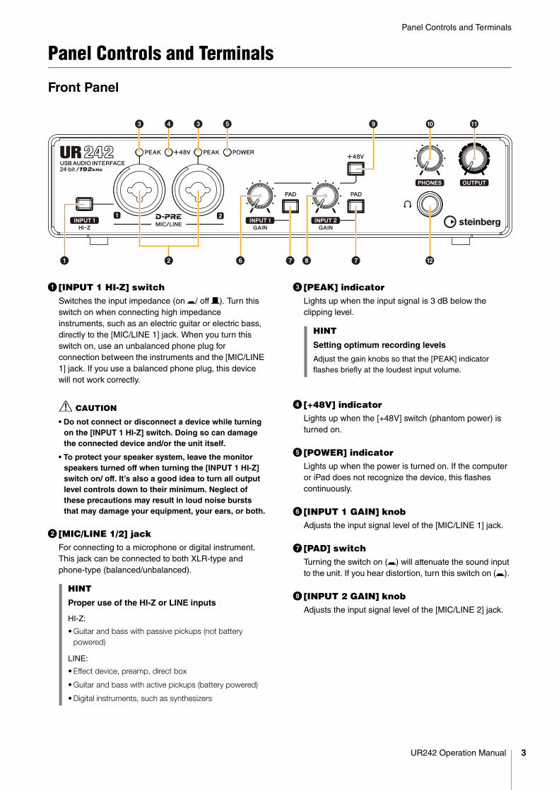
1 [INPUT 1 HI-Z] switchSwitches the input impedance (on O/ off N). Turn this switch on when connecting high impedance instruments, such as an electric guitar or electric bass, directly to the [MIC/LINE 1] jack. When you turn this switch on, use an unbalanced phone plug for connection between the instruments and the [MIC/LINE 1] jack. If you use a balanced phone plug, this device will not work correctly.
CAUTION
• Do not connect or disconnect a device while turning on the [INPUT 1 HI-Z] switch. Doing so can damage the connected device and/or the unit itself.
• To protect your speaker system, leave the monitor speakers turned off when turning the [INPUT 1 HI-Z] switch on/ off. It’s also a good idea to turn all output level controls down to their minimum. Neglect of these precautions may result in loud noise bursts that may damage your equipment, your ears, or both.
2 [MIC/LINE 1/2] jackFor connecting to a microphone or digital instrument. This jack can be connected to both XLR-type and phone-type (balanced/unbalanced).
3 [PEAK] indicatorLights up when the input signal is 3 dB below the clipping level.
4 [+48V] indicatorLights up when the [+48V] switch (phantom power) is turned on.
5 [POWER] indicatorLights up when the power is turned on. If the computer or iPad does not recognize the device, this flashes continuously.
6 [INPUT 1 GAIN] knobAdjusts the input signal level of the [MIC/LINE 1] jack.
7 [PAD] switchTurning the switch on (O) will attenuate the sound input to the unit. If you hear distortion, turn this switch on (O).
8 [INPUT 2 GAIN] knobAdjusts the input signal level of the [MIC/LINE 2] jack.
8
9
1 2
3 4 5
6 7
) !3
@7
HINT
Proper use of the HI-Z or LINE inputs
HI-Z:
• Guitar and bass with passive pickups (not battery powered)
LINE:
• Effect device, preamp, direct box
• Guitar and bass with active pickups (battery powered)
• Digital instruments, such as synthesizers
HINT
Setting optimum recording levels
Adjust the gain knobs so that the [PEAK] indicator flashes briefly at the loudest input volume.
UR242 Operation Manual 3
Panel Controls and Terminals
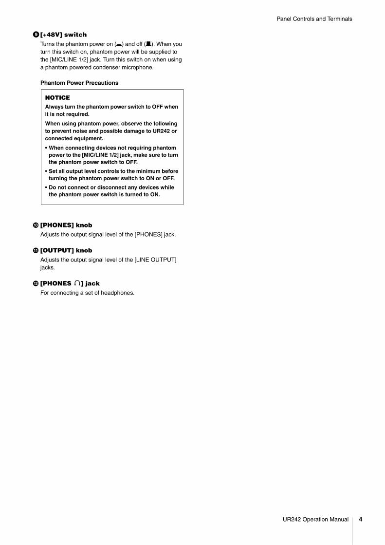
9 [+48V] switchTurns the phantom power on (O) and off (N). When you turn this switch on, phantom power will be supplied to the [MIC/LINE 1/2] jack. Turn this switch on when using a phantom powered condenser microphone.
Phantom Power Precautions
) [PHONES] knobAdjusts the output signal level of the [PHONES] jack.
! [OUTPUT] knobAdjusts the output signal level of the [LINE OUTPUT] jacks.
@ [PHONES ] jackFor connecting a set of headphones.
NOTICEAlways turn the phantom power switch to OFF when it is not required.
When using phantom power, observe the following to prevent noise and possible damage to UR242 or connected equipment.
• When connecting devices not requiring phantom power to the [MIC/LINE 1/2] jack, make sure to turn the phantom power switch to OFF.
• Set all output level controls to the minimum before turning the phantom power switch to ON or OFF.
• Do not connect or disconnect any devices while the phantom power switch is turned to ON.
UR242 Operation Manual 4
Panel Controls and Terminals
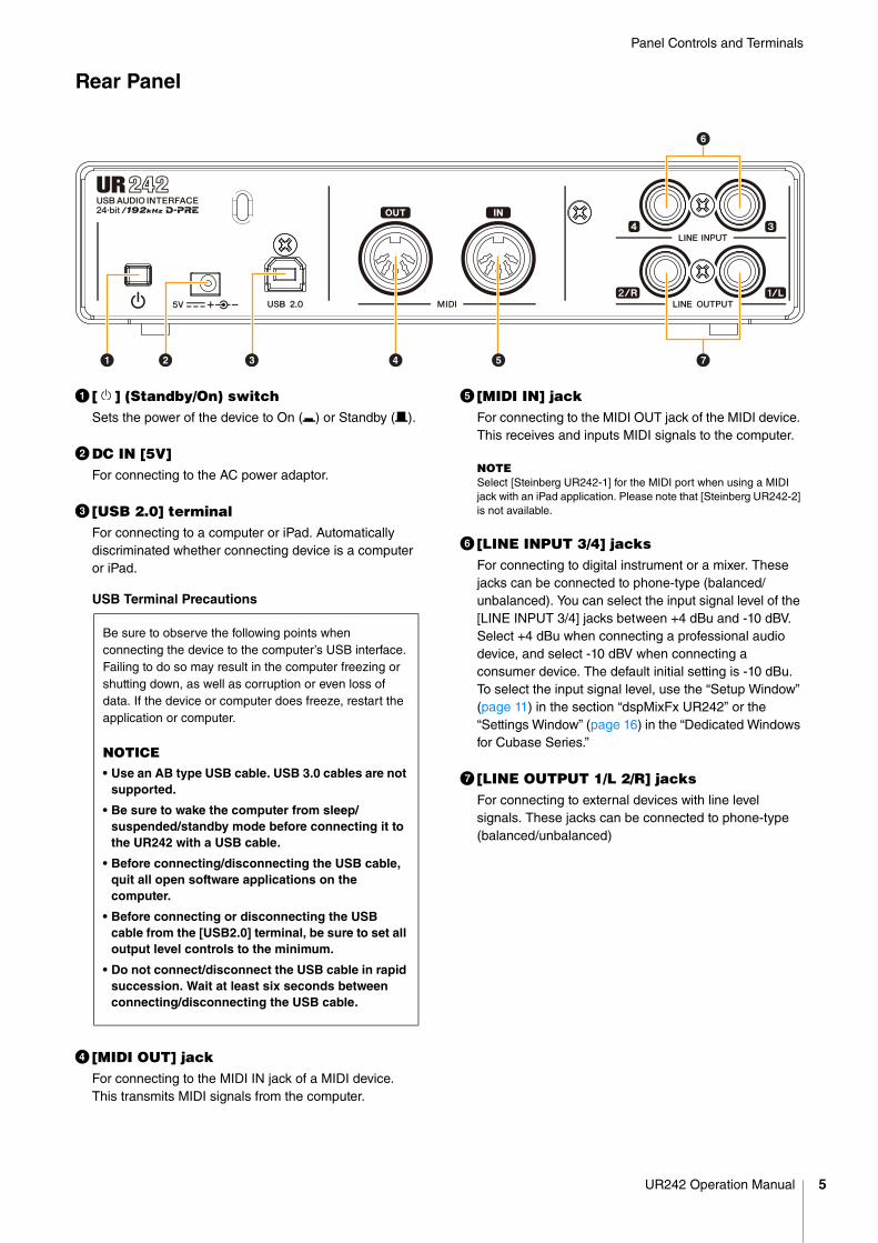
Rear Panel
1 [ ] (Standby/On) switchSets the power of the device to On (O) or Standby (N).
2DC IN [5V]For connecting to the AC power adaptor.
3 [USB 2.0] terminalFor connecting to a computer or iPad. Automatically discriminated whether connecting device is a computer or iPad.
USB Terminal Precautions
4 [MIDI OUT] jackFor connecting to the MIDI IN jack of a MIDI device. This transmits MIDI signals from the computer.
5 [MIDI IN] jackFor connecting to the MIDI OUT jack of the MIDI device. This receives and inputs MIDI signals to the computer.
NOTESelect [Steinberg UR242-1] for the MIDI port when using a MIDI jack with an iPad application. Please note that [Steinberg UR242-2] is not available.
6 [LINE INPUT 3/4] jacksFor connecting to digital instrument or a mixer. These jacks can be connected to phone-type (balanced/unbalanced). You can select the input signal level of the [LINE INPUT 3/4] jacks between +4 dBu and -10 dBV. Select +4 dBu when connecting a professional audio device, and select -10 dBV when connecting a consumer device. The default initial setting is -10 dBu. To select the input signal level, use the “Setup Window” (page 11) in the section “dspMixFx UR242” or the “Settings Window” (page 16) in the “Dedicated Windows for Cubase Series.”
7 [LINE OUTPUT 1/L 2/R] jacksFor connecting to external devices with line level signals. These jacks can be connected to phone-type (balanced/unbalanced)
54
6
321 7
Be sure to observe the following points when connecting the device to the computer’s USB interface. Failing to do so may result in the computer freezing or shutting down, as well as corruption or even loss of data. If the device or computer does freeze, restart the application or computer.
NOTICE• Use an AB type USB cable. USB 3.0 cables are not
supported.
• Be sure to wake the computer from sleep/suspended/standby mode before connecting it to the UR242 with a USB cable.
• Before connecting/disconnecting the USB cable, quit all open software applications on the computer.
• Before connecting or disconnecting the USB cable from the [USB2.0] terminal, be sure to set all output level controls to the minimum.
• Do not connect/disconnect the USB cable in rapid succession. Wait at least six seconds between connecting/disconnecting the USB cable.
UR242 Operation Manual 5
Panel Controls and Terminals
SoftwareThis section explains software operations for using the UR242 with a computer.
Yamaha Steinberg USB DriverYamaha Steinberg USB Driver is a software program that allows communication between the UR242 and a computer. In Control Panel, you can configure the basic settings for the audio driver (Windows) or confirm the audio driver information (Mac).
Windows
How to Open the Window
• Select [Control Panel] [Hardware and Sound] or [Sounds, Speech, and Audio Devices] [Yamaha Steinberg USB Driver].
• From the Cubase series menu, select [Devices] [Device Setup...] [Yamaha Steinberg USB ASIO] [Control Panel].
How to Select Windows
Click the upper tabs to select the desired window.
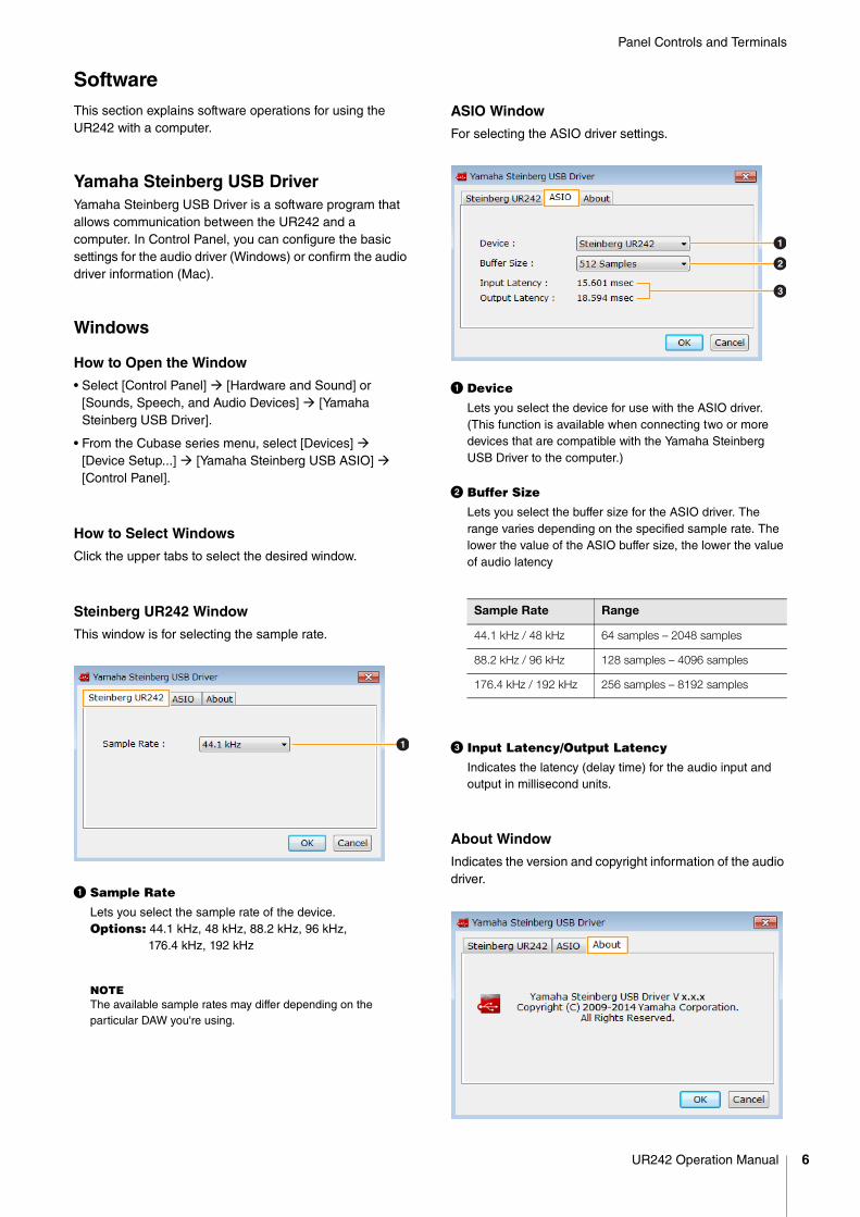
Steinberg UR242 Window
This window is for selecting the sample rate.
1 Sample Rate
Lets you select the sample rate of the device. Options: 44.1 kHz, 48 kHz, 88.2 kHz, 96 kHz, 176.4 kHz, 192 kHz
NOTEThe available sample rates may differ depending on the particular DAW you're using.
ASIO Window
For selecting the ASIO driver settings.
1 Device
Lets you select the device for use with the ASIO driver. (This function is available when connecting two or more devices that are compatible with the Yamaha Steinberg USB Driver to the computer.)
2 Buffer Size
Lets you select the buffer size for the ASIO driver. The range varies depending on the specified sample rate. The lower the value of the ASIO buffer size, the lower the value of audio latency
3 Input Latency/Output Latency
Indicates the latency (delay time) for the audio input and output in millisecond units.
About Window
Indicates the version and copyright information of the audio driver.
1
Sample Rate Range
44.1 kHz / 48 kHz 64 samples – 2048 samples
88.2 kHz / 96 kHz 128 samples – 4096 samples
176.4 kHz / 192 kHz 256 samples – 8192 samples
1
2
3
UR242 Operation Manual 6
Panel Controls and Terminals
Mac
How to Open the Window
• Select [System Preferences] [Yamaha Steinberg USB].
• From the Cubase series menu, select [Devices] [Device Setup...] [Steinberg UR242] [Control Panel] [Open Config App].
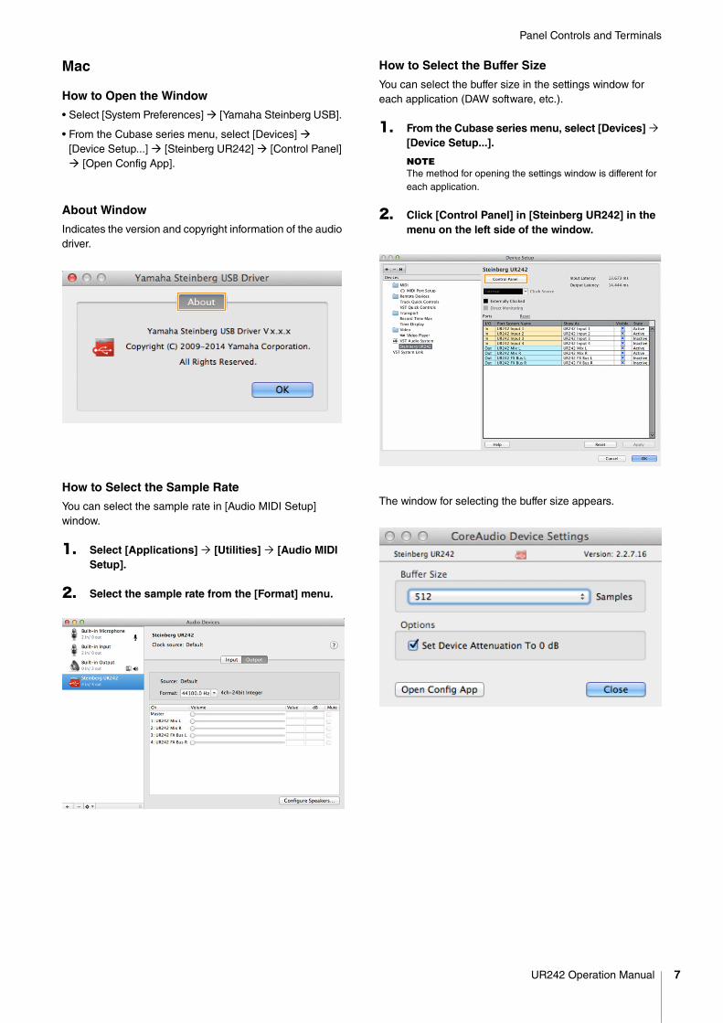
About Window
Indicates the version and copyright information of the audio driver.
How to Select the Sample Rate
You can select the sample rate in [Audio MIDI Setup] window.
1. Select [Applications] [Utilities] [Audio MIDI Setup].
2. Select the sample rate from the [Format] menu.
How to Select the Buffer Size
You can select the buffer size in the settings window for each application (DAW software, etc.).
1. From the Cubase series menu, select [Devices] [Device Setup...].
NOTEThe method for opening the settings window is different for each application.
2. Click [Control Panel] in [Steinberg UR242] in the menu on the left side of the window.
The window for selecting the buffer size appears.
UR242 Operation Manual 7
Panel Controls and Terminals
dspMixFx UR242This software is for operating the convenient built-in DSP mixer and DSP effects. The DSP mixer allows you to mix up to four input channels down to one stereo output. A number of DSP effects for processing the input signals are also provided, and since the processing/mixing is hardware-based, there is no monitoring latency.
NOTE
You cannot operate dspMixFx UR242 while a Cubase series DAW is running. When Cubase is running, configure the DSP mixer and DSP effect from “Dedicated Windows for Cubase Series” (page 13).
How to Open the Window
Windows
[All Programs] or [All apps] [Steinberg UR242] [dspMixFx UR242]
Mac
[Applications] [dspMixFx UR242]
Controls and Functions
Tool Area
This is the area for configuring the overall common settings of dspMixFx UR242.
1 Quit
Quits dspMixFx UR242.
2 Minimize
Minimizes the dspMixFx UR242 window.
3 Menu
Provides four different menus for various settings.
4 Scene
Indicates the scene name. You can change the scene name by clicking on it. Clicking the button on the right opens the window for calling up other scenes. Call up the desired scene by clicking it. To cancel calling up the scene, click outside of the window.
5 STORE
Opens the Scene Store window. Enter the desired scene name into the STORE NAME field. Select the destination for storing the scene in the No. NAME field. Click [OK] to store the scene.
6 Selecting windows
Selects the desired dspMixFx UR242 window. The selected window icon lights in red.
7 Help
Opens the Operation Manual (this manual).
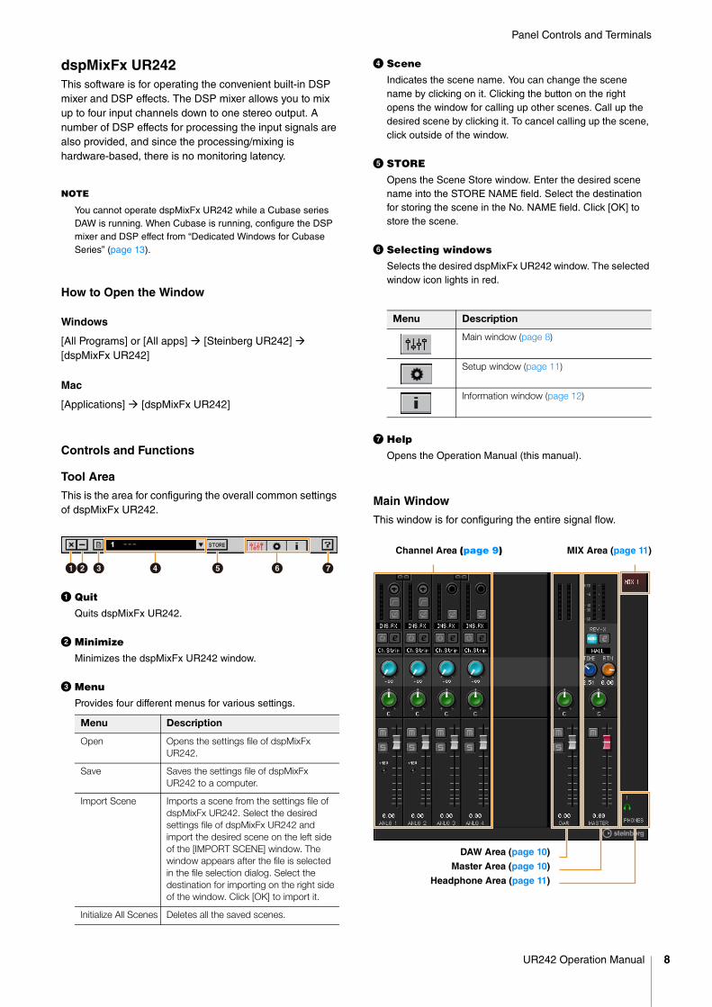
Main Window
This window is for configuring the entire signal flow.
Menu Description
Open Opens the settings file of dspMixFx UR242.
Save Saves the settings file of dspMixFx UR242 to a computer.
Import Scene Imports a scene from the settings file of dspMixFx UR242. Select the desired settings file of dspMixFx UR242 and import the desired scene on the left side of the [IMPORT SCENE] window. The window appears after the file is selected in the file selection dialog. Select the destination for importing on the right side of the window. Click [OK] to import it.
Initialize All Scenes Deletes all the saved scenes.
12 3 4 5 6 7
Menu Description
Main window (page 8)
Setup window (page 11)
Information window (page 12)
Channel Area (page 9) MIX Area (page 11)
DAW Area (page 10)
Master Area (page 10)
Headphone Area (page 11)
UR242 Operation Manual 8
Panel Controls and Terminals
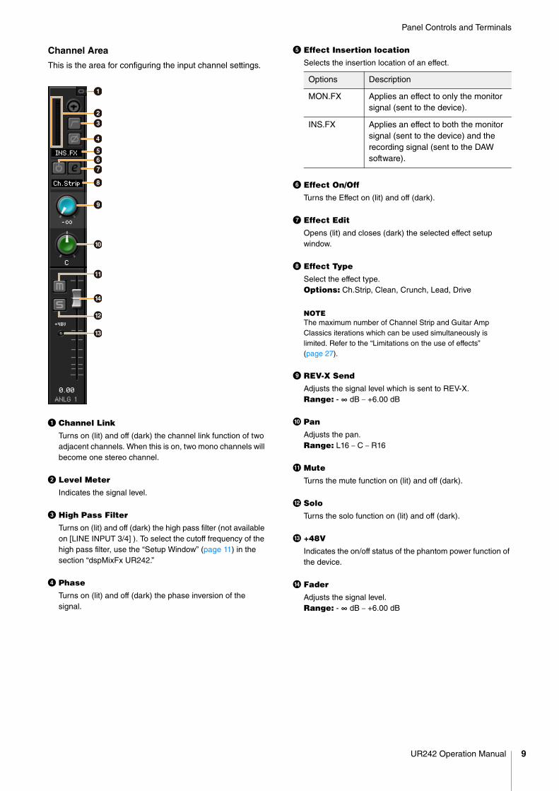
Channel Area
This is the area for configuring the input channel settings.
1 Channel Link
Turns on (lit) and off (dark) the channel link function of two adjacent channels. When this is on, two mono channels will become one stereo channel.
2 Level Meter
Indicates the signal level.
3 High Pass Filter
Turns on (lit) and off (dark) the high pass filter (not available on [LINE INPUT 3/4] ). To select the cutoff frequency of the high pass filter, use the “Setup Window” (page 11) in the section “dspMixFx UR242.”
4 Phase
Turns on (lit) and off (dark) the phase inversion of the signal.
5 Effect Insertion location
Selects the insertion location of an effect.
6 Effect On/Off
Turns the Effect on (lit) and off (dark).
7 Effect Edit
Opens (lit) and closes (dark) the selected effect setup window.
8 Effect Type
Select the effect type.Options: Ch.Strip, Clean, Crunch, Lead, Drive
NOTEThe maximum number of Channel Strip and Guitar Amp Classics iterations which can be used simultaneously is limited. Refer to the “Limitations on the use of effects”(page 27).
9 REV-X Send
Adjusts the signal level which is sent to REV-X.Range: - ∞ dB – +6.00 dB
) Pan
Adjusts the pan.Range: L16 – C – R16
! Mute
Turns the mute function on (lit) and off (dark).
@ Solo
Turns the solo function on (lit) and off (dark).
# +48V
Indicates the on/off status of the phantom power function of the device.
$ Fader
Adjusts the signal level.Range: - ∞ dB – +6.00 dB
4
)
1
23
$
#
!
@
567
8
9
Options Description
MON.FX Applies an effect to only the monitor signal (sent to the device).
INS.FX Applies an effect to both the monitor signal (sent to the device) and the recording signal (sent to the DAW software).
UR242 Operation Manual 9
Panel Controls and Terminals
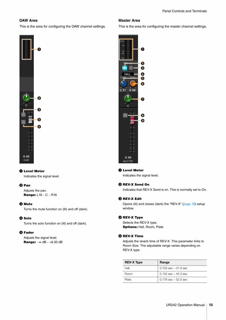
DAW Area
This is the area for configuring the DAW channel settings.
1 Level Meter
Indicates the signal level.
2 Pan
Adjusts the pan.Range: L16 – C – R16
3 Mute
Turns the mute function on (lit) and off (dark).
4 Solo
Turns the solo function on (lit) and off (dark).
5 Fader
Adjusts the signal level.Range: - ∞ dB – +6.00 dB
Master Area
This is the area for configuring the master channel settings.
1 Level Meter
Indicates the signal level.
2 REV-X Send On
Indicates that REV-X Send is on. This is normally set to On.
3 REV-X Edit
Opens (lit) and closes (dark) the “REV-X” (page 18) setup window.
4 REV-X Type
Selects the REV-X type.Options: Hall, Room, Plate
5 REV-X Time
Adjusts the reverb time of REV-X. This parameter links to Room Size. The adjustable range varies depending on REV-X type.
2
3
4
5
1
REV-X Type Range
Hall 0.103 sec – 31.0 sec
Room 0.152 sec – 45.3 sec
Plate 0.176 sec – 52.0 sec
1
2
3
54
6
7
8
9
UR242 Operation Manual 10
Panel Controls and Terminals
6 REV-X Return Level
Adjusts the return level of REV-X.Range: - ∞ dB – +6.00 dB
7 Pan
Adjusts the pan position.Range: L16 – C – R16
8 Mute
Turns the mute function on (lit) and off (dark).
9 Fader
Adjusts the signal level.Range: - ∞ dB – +6.00 dB
MIX Area
Indicates the MIX object. The UR242 can be set only to MIX1.
Headphone Area
Indicates the monitor signal that is sent from the[PHONES ] jack. This is normally on.
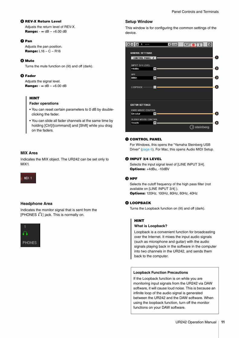
Setup Window
This window is for configuring the common settings of the device.
1 CONTROL PANEL
For Windows, this opens the “Yamaha Steinberg USB Driver” (page 6). For Mac, this opens Audio MIDI Setup.
2 INPUT 3/4 LEVEL
Selects the input signal level of [LINE INPUT 3/4].Options: +4dBu, -10dBV
3 HPF
Selects the cutoff frequency of the high pass filter (not available on [LINE INPUT 3/4] ).Options: 120Hz, 100Hz, 80Hz, 60Hz, 40Hz
4 LOOPBACK
Turns the Loopback function on (lit) and off (dark).
HINTFader operations
• You can reset certain parameters to 0 dB by double-clicking the fader.
• You can slide all fader channels at the same time by holding [Ctrl]/[command] and [Shift] while you drag on the faders.
HINTWhat is Loopback?
Loopback is a convenient function for broadcasting over the Internet. It mixes the input audio signals (such as microphone and guitar) with the audio signals playing back in the software in the computer into two channels in the UR242, and sends them back to the computer.
Loopback Function Precautions
If the Loopback function is on while you are monitoring input signals from the UR242 via DAW software, it will cause loud noise. This is because an infinite loop of the audio signal is generated between the UR242 and the DAW software. When using the loopback function, turn off the monitor functions on your DAW software.
1
2
3
4
5
6
UR242 Operation Manual 11
Panel Controls and Terminals
5 KNOB MOUSE CONTROL
Selects the method of operating the knobs on dspMixFx UR242.
6 SLIDER MOUSE CONTROL
Selects the method of operating the sliders and faders on dspMixFx UR242.
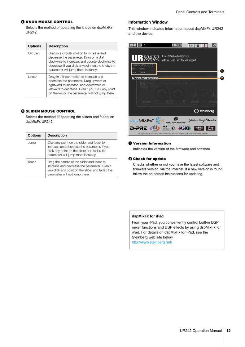
Information Window
This window indicates information about dspMixFx UR242 and the device.
1 Version Information
Indicates the version of the firmware and software.
2 Check for update
Checks whether or not you have the latest software and firmware version, via the Internet. If a new version is found, follow the on-screen instructions for updating.
Options Description
Circular Drag in a circular motion to increase and decrease the parameter. Drag on a dial clockwise to increase, and counterclockwise to decrease. If you click any point on the knob, the parameter will jump there instantly.
Linear Drag in a linear motion to increase and decrease the parameter. Drag upward or rightward to increase, and downward or leftward to decrease. Even if you click any point on the knob, the parameter will not jump there.
Options Description
Jump Click any point on the slider and fader to increase and decrease the parameter. If you click any point on the slider and fader, the parameter will jump there instantly.
Touch Drag the handle of the slider and fader to increase and decrease the parameter. Even if you click any point on the slider and fader, the parameter will not jump there.
dspMixFx for iPad
From your iPad, you conveniently control built-in DSP mixer functions and DSP effects by using dspMixFx for iPad. For details on dspMixFx for iPad, see the Steinberg web site below.http://www.steinberg.net/
1
2
UR242 Operation Manual 12
Panel Controls and Terminals
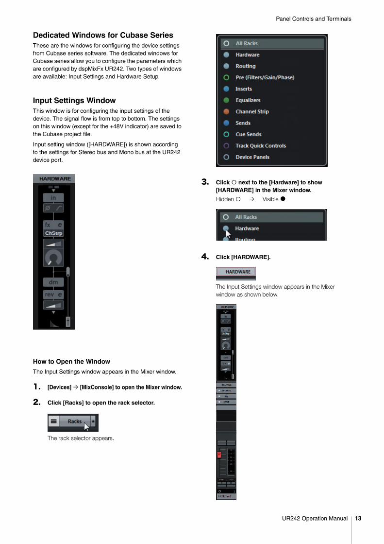
Dedicated Windows for Cubase SeriesThese are the windows for configuring the device settings from Cubase series software. The dedicated windows for Cubase series allow you to configure the parameters which are configured by dspMixFx UR242. Two types of windows are available: Input Settings and Hardware Setup.
Input Settings WindowThis window is for configuring the input settings of the device. The signal flow is from top to bottom. The settings on this window (except for the +48V indicator) are saved to the Cubase project file.
Input setting window ([HARDWARE]) is shown according to the settings for Stereo bus and Mono bus at the UR242 device port.
How to Open the Window
The Input Settings window appears in the Mixer window.
1. [Devices] [MixConsole] to open the Mixer window.
2. Click [Racks] to open the rack selector.
The rack selector appears.
3. Click next to the [Hardware] to show [HARDWARE] in the Mixer window.
Hidden Visible I
4. Click [HARDWARE].
The Input Settings window appears in the Mixer window as shown below.
UR242 Operation Manual 13
Panel Controls and Terminals
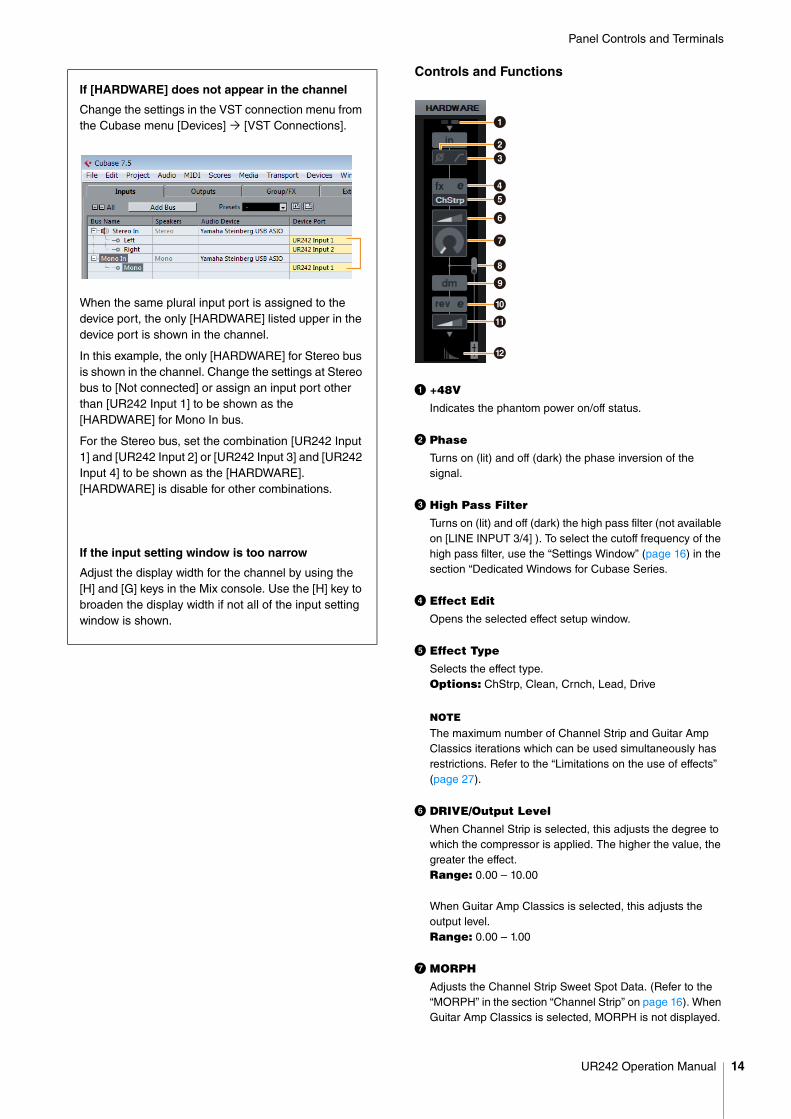
Controls and Functions
1 +48V
Indicates the phantom power on/off status.
2 Phase
Turns on (lit) and off (dark) the phase inversion of the signal.
3 High Pass Filter
Turns on (lit) and off (dark) the high pass filter (not available on [LINE INPUT 3/4] ). To select the cutoff frequency of the high pass filter, use the “Settings Window” (page 16) in the section “Dedicated Windows for Cubase Series.
4 Effect Edit
Opens the selected effect setup window.
5 Effect Type
Selects the effect type.Options: ChStrp, Clean, Crnch, Lead, Drive
NOTE
The maximum number of Channel Strip and Guitar Amp Classics iterations which can be used simultaneously has restrictions. Refer to the “Limitations on the use of effects” (page 27).
6 DRIVE/Output Level
When Channel Strip is selected, this adjusts the degree to which the compressor is applied. The higher the value, the greater the effect.Range: 0.00 – 10.00
When Guitar Amp Classics is selected, this adjusts the output level. Range: 0.00 – 1.00
7 MORPH
Adjusts the Channel Strip Sweet Spot Data. (Refer to the “MORPH” in the section “Channel Strip” on page 16). When Guitar Amp Classics is selected, MORPH is not displayed.
If [HARDWARE] does not appear in the channel
Change the settings in the VST connection menu from the Cubase menu [Devices] [VST Connections].
When the same plural input port is assigned to the device port, the only [HARDWARE] listed upper in the device port is shown in the channel.
In this example, the only [HARDWARE] for Stereo bus is shown in the channel. Change the settings at Stereo bus to [Not connected] or assign an input port other than [UR242 Input 1] to be shown as the [HARDWARE] for Mono In bus.
For the Stereo bus, set the combination [UR242 Input 1] and [UR242 Input 2] or [UR242 Input 3] and [UR242 Input 4] to be shown as the [HARDWARE]. [HARDWARE] is disable for other combinations.
If the input setting window is too narrow
Adjust the display width for the channel by using the [H] and [G] keys in the Mix console. Use the [H] key to broaden the display width if not all of the input setting window is shown.
1
23
45
6
7
8
9
)
!
@
UR242 Operation Manual 14
Panel Controls and Terminals
8 Effect Insertion Location
Selects the insertion location of an effect.
9 Output Position of the Direct Monitoring Signal
Indicates the position from which the audio signals for monitoring will be output when turning on Direct Monitoring in the device settings on Cubase.
) REV-X Edit
Opens the “REV-X” (page 18) setup window.
! REV-X Send
Adjusts the signal level which is sent to the REV-X. Range: - ∞ dB – +6.00 dB
@ Reverb Routing Edit
Opens the “Reverb Routing Window” (page 15) in the section “Dedicated Windows for Cubase Series.”
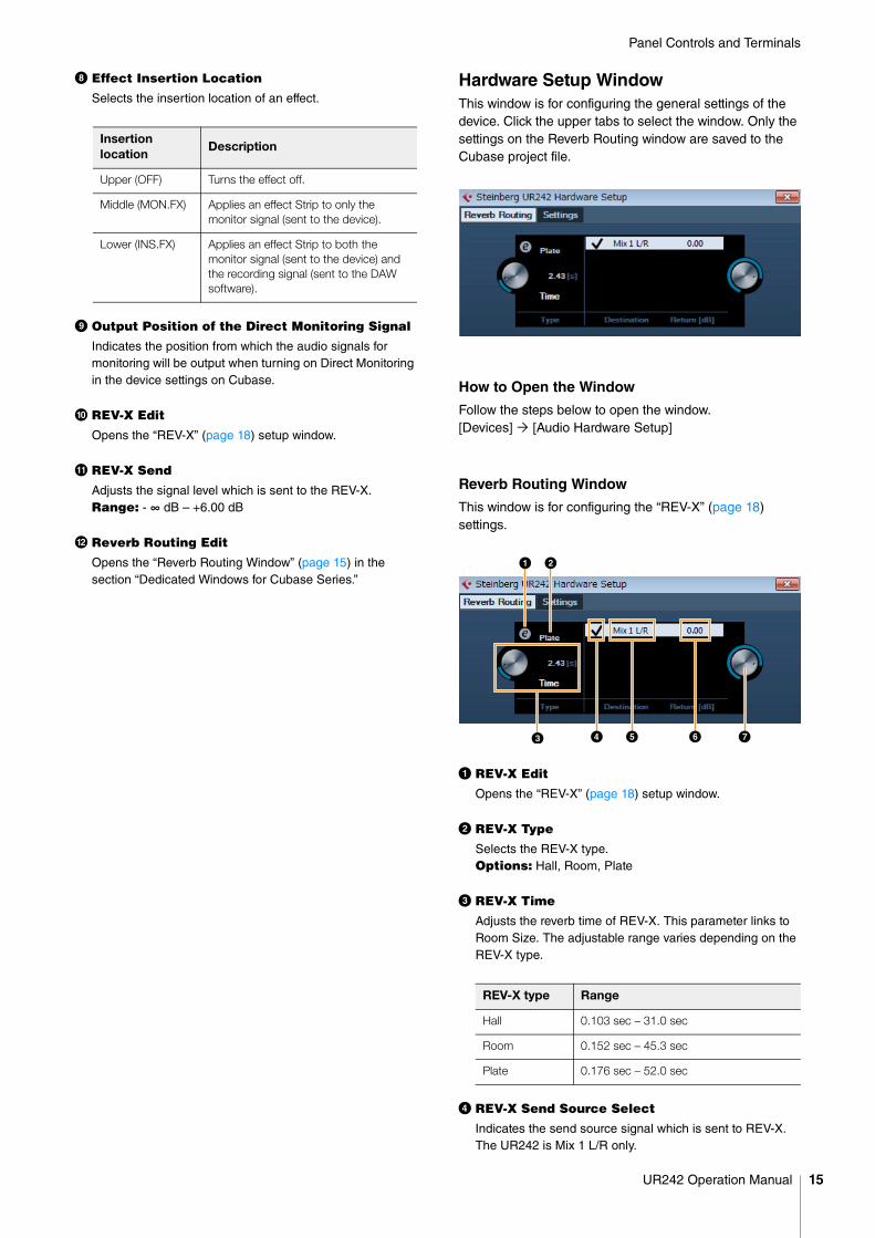
Hardware Setup WindowThis window is for configuring the general settings of the device. Click the upper tabs to select the window. Only the settings on the Reverb Routing window are saved to the Cubase project file.
How to Open the Window
Follow the steps below to open the window.[Devices] [Audio Hardware Setup]
Reverb Routing Window
This window is for configuring the “REV-X” (page 18) settings.
1 REV-X Edit
Opens the “REV-X” (page 18) setup window.
2 REV-X Type
Selects the REV-X type.Options: Hall, Room, Plate
3 REV-X Time
Adjusts the reverb time of REV-X. This parameter links to Room Size. The adjustable range varies depending on the REV-X type.
4 REV-X Send Source Select
Indicates the send source signal which is sent to REV-X. The UR242 is Mix 1 L/R only.
Insertion location
Description
Upper (OFF) Turns the effect off.
Middle (MON.FX) Applies an effect Strip to only the monitor signal (sent to the device).
Lower (INS.FX) Applies an effect Strip to both the monitor signal (sent to the device) and the recording signal (sent to the DAW software).
REV-X type Range
Hall 0.103 sec – 31.0 sec
Room 0.152 sec – 45.3 sec
Plate 0.176 sec – 52.0 sec
UR242 Operation Manual 15
Panel Controls and Terminals
5 REV-X Send Source
Indicates the signal which is sent to REV-X.
6 REV-X Return Level
Indicates the return level of REV-X.
7 REV-X Return Level Knob
Adjusts the return level of the selected (highlighted) signal. Range: - ∞ dB – +6.00 dB
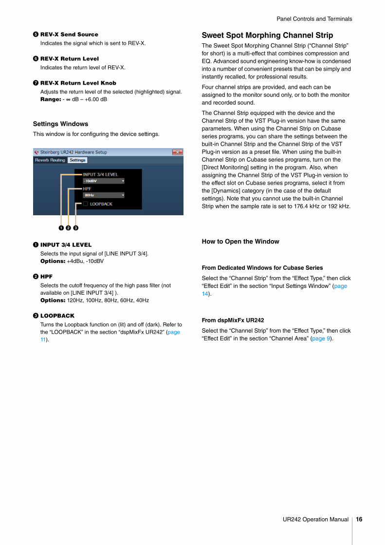
Settings Windows
This window is for configuring the device settings.
1 INPUT 3/4 LEVEL
Selects the input signal of [LINE INPUT 3/4]. Options: +4dBu, -10dBV
2 HPF
Selects the cutoff frequency of the high pass filter (not available on [LINE INPUT 3/4] ). Options: 120Hz, 100Hz, 80Hz, 60Hz, 40Hz
3 LOOPBACK
Turns the Loopback function on (lit) and off (dark). Refer to the “LOOPBACK” in the section “dspMixFx UR242” (page 11).
Sweet Spot Morphing Channel StripThe Sweet Spot Morphing Channel Strip (“Channel Strip” for short) is a multi-effect that combines compression and EQ. Advanced sound engineering know-how is condensed into a number of convenient presets that can be simply and instantly recalled, for professional results.
Four channel strips are provided, and each can be assigned to the monitor sound only, or to both the monitor and recorded sound.
The Channel Strip equipped with the device and the Channel Strip of the VST Plug-in version have the same parameters. When using the Channel Strip on Cubase series programs, you can share the settings between the built-in Channel Strip and the Channel Strip of the VST Plug-in version as a preset file. When using the built-in Channel Strip on Cubase series programs, turn on the [Direct Monitoring] setting in the program. Also, when assigning the Channel Strip of the VST Plug-in version to the effect slot on Cubase series programs, select it from the [Dynamics] category (in the case of the default settings). Note that you cannot use the built-in Channel Strip when the sample rate is set to 176.4 kHz or 192 kHz.
How to Open the Window
From Dedicated Windows for Cubase Series
Select the “Channel Strip” from the “Effect Type,” then click “Effect Edit” in the section “Input Settings Window” (page 14).
From dspMixFx UR242
Select the “Channel Strip” from the “Effect Type,” then click “Effect Edit” in the section “Channel Area” (page 9).
UR242 Operation Manual 16
Panel Controls and Terminals
Controls and Functions
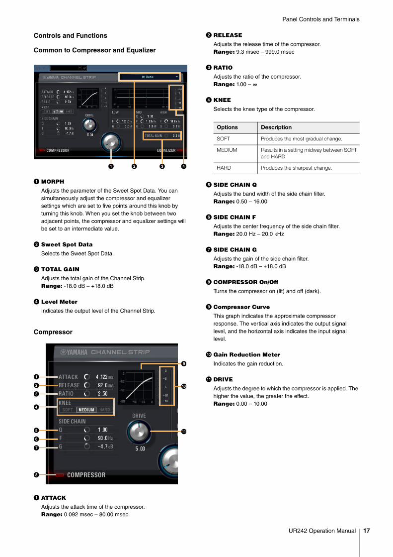
Common to Compressor and Equalizer
1 MORPH
Adjusts the parameter of the Sweet Spot Data. You can simultaneously adjust the compressor and equalizer settings which are set to five points around this knob by turning this knob. When you set the knob between two adjacent points, the compressor and equalizer settings will be set to an intermediate value.
2 Sweet Spot Data
Selects the Sweet Spot Data.
3 TOTAL GAIN
Adjusts the total gain of the Channel Strip. Range: -18.0 dB – +18.0 dB
4 Level Meter
Indicates the output level of the Channel Strip.
Compressor
1 ATTACK
Adjusts the attack time of the compressor.Range: 0.092 msec – 80.00 msec
2 RELEASE
Adjusts the release time of the compressor.Range: 9.3 msec – 999.0 msec
3 RATIO
Adjusts the ratio of the compressor.Range: 1.00 – ∞
4 KNEE
Selects the knee type of the compressor.
5 SIDE CHAIN Q
Adjusts the band width of the side chain filter.Range: 0.50 – 16.00
6 SIDE CHAIN F
Adjusts the center frequency of the side chain filter.Range: 20.0 Hz – 20.0 kHz
7 SIDE CHAIN G
Adjusts the gain of the side chain filter.Range: -18.0 dB – +18.0 dB
8 COMPRESSOR On/Off
Turns the compressor on (lit) and off (dark).
9 Compressor Curve
This graph indicates the approximate compressor response. The vertical axis indicates the output signal level, and the horizontal axis indicates the input signal level.
) Gain Reduction Meter
Indicates the gain reduction.
! DRIVE
Adjusts the degree to which the compressor is applied. The higher the value, the greater the effect.Range: 0.00 – 10.00
Options Description
SOFT Produces the most gradual change.
MEDIUM Results in a setting midway between SOFT and HARD.
HARD Produces the sharpest change.
UR242 Operation Manual 17
Panel Controls and Terminals
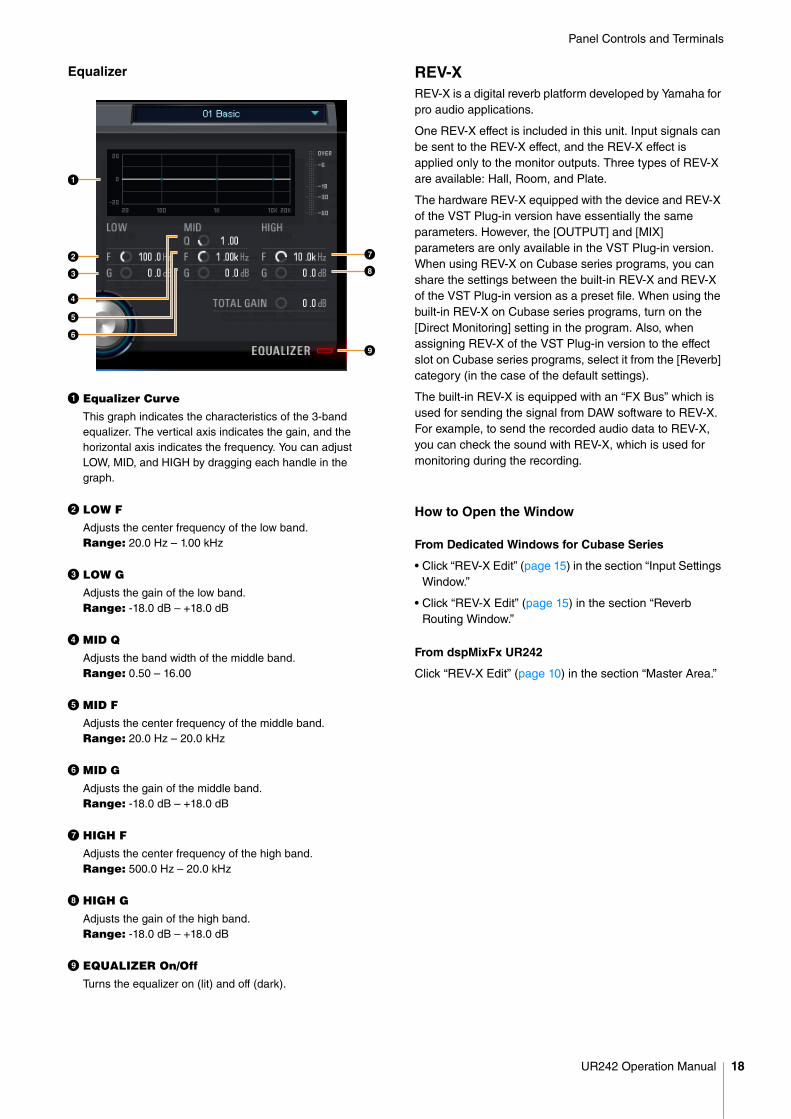
Equalizer
1 Equalizer Curve
This graph indicates the characteristics of the 3-band equalizer. The vertical axis indicates the gain, and the horizontal axis indicates the frequency. You can adjust LOW, MID, and HIGH by dragging each handle in the graph.
2 LOW F
Adjusts the center frequency of the low band.Range: 20.0 Hz – 1.00 kHz
3 LOW G
Adjusts the gain of the low band.Range: -18.0 dB – +18.0 dB
4 MID Q
Adjusts the band width of the middle band.Range: 0.50 – 16.00
5 MID F
Adjusts the center frequency of the middle band.Range: 20.0 Hz – 20.0 kHz
6 MID G
Adjusts the gain of the middle band.Range: -18.0 dB – +18.0 dB
7 HIGH F
Adjusts the center frequency of the high band.Range: 500.0 Hz – 20.0 kHz
8 HIGH G
Adjusts the gain of the high band.Range: -18.0 dB – +18.0 dB
9 EQUALIZER On/Off
Turns the equalizer on (lit) and off (dark).
REV-XREV-X is a digital reverb platform developed by Yamaha for pro audio applications.
One REV-X effect is included in this unit. Input signals can be sent to the REV-X effect, and the REV-X effect is applied only to the monitor outputs. Three types of REV-X are available: Hall, Room, and Plate.
The hardware REV-X equipped with the device and REV-X of the VST Plug-in version have essentially the same parameters. However, the [OUTPUT] and [MIX] parameters are only available in the VST Plug-in version. When using REV-X on Cubase series programs, you can share the settings between the built-in REV-X and REV-X of the VST Plug-in version as a preset file. When using the built-in REV-X on Cubase series programs, turn on the [Direct Monitoring] setting in the program. Also, when assigning REV-X of the VST Plug-in version to the effect slot on Cubase series programs, select it from the [Reverb] category (in the case of the default settings).
The built-in REV-X is equipped with an “FX Bus” which is used for sending the signal from DAW software to REV-X. For example, to send the recorded audio data to REV-X, you can check the sound with REV-X, which is used for monitoring during the recording.
How to Open the Window
From Dedicated Windows for Cubase Series
• Click “REV-X Edit” (page 15) in the section “Input Settings Window.”
• Click “REV-X Edit” (page 15) in the section “Reverb Routing Window.”
From dspMixFx UR242
Click “REV-X Edit” (page 10) in the section “Master Area.”
UR242 Operation Manual 18
Panel Controls and Terminals
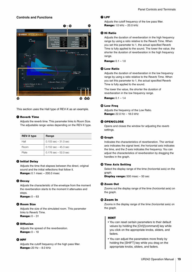
Controls and Functions
This section uses the Hall type of REV-X as an example.
1 Reverb Time
Adjusts the reverb time. This parameter links to Room Size. The adjustable range varies depending on the REV-X type.
2 Initial Delay
Adjusts the time that elapses between the direct, original sound and the initial reflections that follow it. Range: 0.1 msec – 200.0 msec
3 Decay
Adjusts the characteristic of the envelope from the moment the reverberation starts to the moment it attenuates and stops.Range: 0 – 63
4 Room Size
Adjusts the size of the simulated room. This parameter links to Reverb Time. Range: 0 – 31
5 Diffusion
Adjusts the spread of the reverberation.Range: 0 – 10
6 HPF
Adjusts the cutoff frequency of the high pass filter.Range: 20 Hz – 8.0 kHz
7 LPF
Adjusts the cutoff frequency of the low pass filter.Range: 1.0 kHz – 20.0 kHz
8 Hi Ratio
Adjusts the duration of reverberation in the high frequency range by using a ratio relative to the Reverb Time. When you set this parameter to 1, the actual specified Reverb Time is fully applied to the sound. The lower the value, the shorter the duration of reverberation in the high frequency range.
Range: 0.1 – 1.0
9 Low Ratio
Adjusts the duration of reverberation in the low frequency range by using a ratio relative to the Reverb Time. When you set this parameter to 1, the actual specified Reverb Time is fully applied to the sound.
The lower the value, the shorter the duration of reverberation in the low frequency range.
Range: 0.1 – 1.4
) Low Freq
Adjusts the frequency of the Low Ratio.Range: 22.0 Hz – 18.0 kHz
! OPEN/CLOSE
Opens and closes the window for adjusting the reverb settings.
@ Graph
Indicates the characteristics of reverberation. The vertical axis indicates the signal level, the horizontal axis indicates the time, and the Z-axis indicates the frequency. You can adjust the characteristics of reverberation by dragging the handles in the graph.
# Time Axis Setting
Select the display range of the time (horizontal axis) on the graph.Display range: 500 msec – 50 sec
$ Zoom Out
Zooms out the display range of the time (horizontal axis) on the graph.
% Zoom InZooms in the display range of the time (horizontal axis) on the graph.
REV-X type Range
Hall 0.103 sec – 31.0 sec
Room 0.152 sec – 45.3 sec
Plate 0.176 sec – 52.0 sec
HINT• You can reset certain parameters to their default
values by holding the [Ctrl]/[command] key while you click on the appropriate knobs, sliders, and faders.
• You can adjust the parameters more finely by holding the [SHIFT] key while you drag on the appropriate knobs, sliders, and faders.
UR242 Operation Manual 19
Panel Controls and Terminals
Guitar Amp ClassicsGuitar Amp Classics are guitar amp simulations that make extensive use of advanced Yamaha modeling technology. Four amp types with different sonic characteristics are provided.
The Guitar Amp Classics equipped with the device and the Guitar Amp Classics of the VST Plug-in version have the same parameters. When using the Guitar Amp Classics on Cubase series programs, you can share the settings between the built-in Guitar Amp Classics and the Guitar Amp Classics of the VST Plug-in version as a preset file. When using the built-in Guitar Amp Classics on Cubase series programs, turn on the [Direct Monitoring] setting in the program. Also, when assigning the Guitar Amp Classics of the VST Plug-in version to the effect slot on Cubase series programs, select it from the [Distortion] category (in the case of the default settings).
Note that Guitar Amp Classics cannot be used when the sample rate is set to 176.4 kHz or 192 kHz.
How to Open the Window
From Dedicated Windows for Cubase Series
Select the “Guitar Amp Classics” from the “Effect Type” , then click “Effect Edit” in the section “Input Settings Window” (page 14).
From the dspMixFx UR242
Select the “Guitar Amp Classics” from the “Effect Type” , then click “Effect Edit” in the section “Channel Area” (page 9).
Controls and Functions
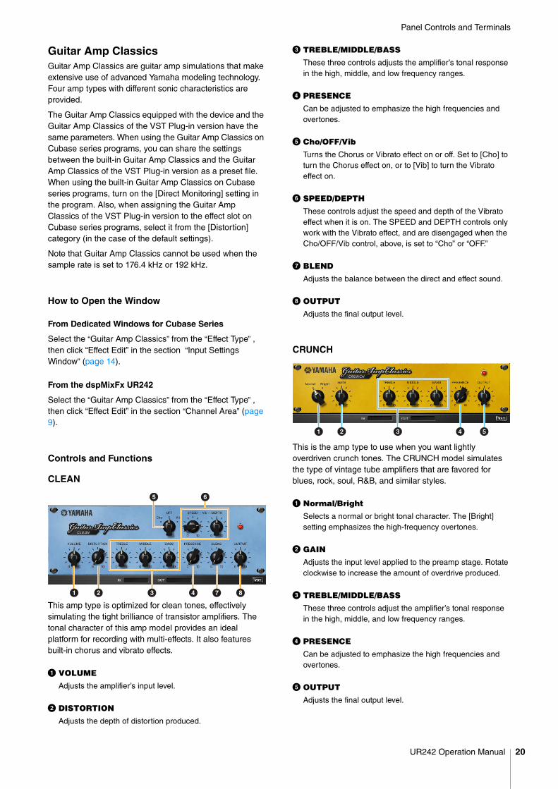
CLEAN
This amp type is optimized for clean tones, effectively simulating the tight brilliance of transistor amplifiers. The tonal character of this amp model provides an ideal platform for recording with multi-effects. It also features built-in chorus and vibrato effects.
1 VOLUME
Adjusts the amplifier’s input level.
2 DISTORTION
Adjusts the depth of distortion produced.
3 TREBLE/MIDDLE/BASS
These three controls adjusts the amplifier’s tonal response in the high, middle, and low frequency ranges.
4 PRESENCE
Can be adjusted to emphasize the high frequencies and overtones.
5 Cho/OFF/Vib
Turns the Chorus or Vibrato effect on or off. Set to [Cho] to turn the Chorus effect on, or to [Vib] to turn the Vibrato effect on.
6 SPEED/DEPTH
These controls adjust the speed and depth of the Vibrato effect when it is on. The SPEED and DEPTH controls only work with the Vibrato effect, and are disengaged when the Cho/OFF/Vib control, above, is set to “Cho” or “OFF.”
7 BLEND
Adjusts the balance between the direct and effect sound.
8 OUTPUT
Adjusts the final output level.
CRUNCH
This is the amp type to use when you want lightly overdriven crunch tones. The CRUNCH model simulates the type of vintage tube amplifiers that are favored for blues, rock, soul, R&B, and similar styles.
1 Normal/Bright
Selects a normal or bright tonal character. The [Bright] setting emphasizes the high-frequency overtones.
2 GAIN
Adjusts the input level applied to the preamp stage. Rotate clockwise to increase the amount of overdrive produced.
3 TREBLE/MIDDLE/BASS
These three controls adjust the amplifier’s tonal response in the high, middle, and low frequency ranges.
4 PRESENCE
Can be adjusted to emphasize the high frequencies and overtones.
5 OUTPUT
Adjusts the final output level.
1 2 3 4 7 8
65
1 2 3 4 5
UR242 Operation Manual 20
Panel Controls and Terminals
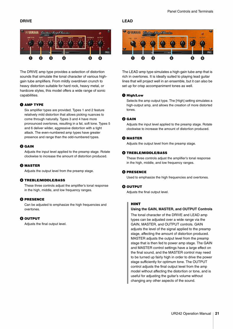
DRIVE
The DRIVE amp type provides a selection of distortion sounds that simulate the tonal character of various high-gain tube amplifiers. From mildly overdriven crunch to heavy distortion suitable for hard rock, heavy metal, or hardcore styles, this model offers a wide range of sonic capabilities.
1 AMP TYPE
Six amplifier types are provided. Types 1 and 2 feature relatively mild distortion that allows picking nuances to come through naturally. Types 3 and 4 have more pronounced overtones, resulting in a fat, soft tone. Types 5 and 6 deliver wilder, aggressive distortion with a tight attack. The even-numbered amp types have greater presence and range than the odd-numbered types.
2 GAIN
Adjusts the input level applied to the preamp stage. Rotate clockwise to increase the amount of distortion produced.
3 MASTER
Adjusts the output level from the preamp stage.
4 TREBLE/MIDDLE/BASS
These three controls adjust the amplifier’s tonal response in the high, middle, and low frequency ranges.
5 PRESENCE
Can be adjusted to emphasize the high frequencies and overtones.
6 OUTPUT
Adjusts the final output level.
LEAD
The LEAD amp type simulates a high-gain tube amp that is rich in overtones. It is ideally suited to playing lead guitar lines that will project well in an ensemble, but it can also be set up for crisp accompaniment tones as well.
1 High/Low
Selects the amp output type. The [High] setting simulates a high-output amp, and allows the creation of more distorted tones.
2 GAIN
Adjusts the input level applied to the preamp stage. Rotate clockwise to increase the amount of distortion produced.
3 MASTER
Adjusts the output level from the preamp stage.
4 TREBLE/MIDDLE/BASS
These three controls adjust the amplifier’s tonal response in the high, middle, and low frequency ranges.
5 PRESENCE
Used to emphasize the high frequencies and overtones.
6 OUTPUT
Adjusts the final output level.
1 2 3 4 5 6
HINTUsing the GAIN, MASTER, and OUTPUT Controls
The tonal character of the DRIVE and LEAD amp types can be adjusted over a wide range via the GAIN, MASTER, and OUTPUT controls. GAIN adjusts the level of the signal applied to the preamp stage, affecting the amount of distortion produced. MASTER adjusts the output level from the preamp stage that is then fed to power amp stage. The GAIN and MASTER control settings have a large effect on the final sound, and the MASTER control may need to be turned up fairly high in order to drive the power stage sufficiently for optimum tone. The OUTPUT control adjusts the final output level from the amp model without affecting the distortion or tone, and is useful for adjusting the guitar’s volume without changing any other aspects of the sound.
1 2 3 4 5 6
UR242 Operation Manual 21
Using the UR242
Using the UR242
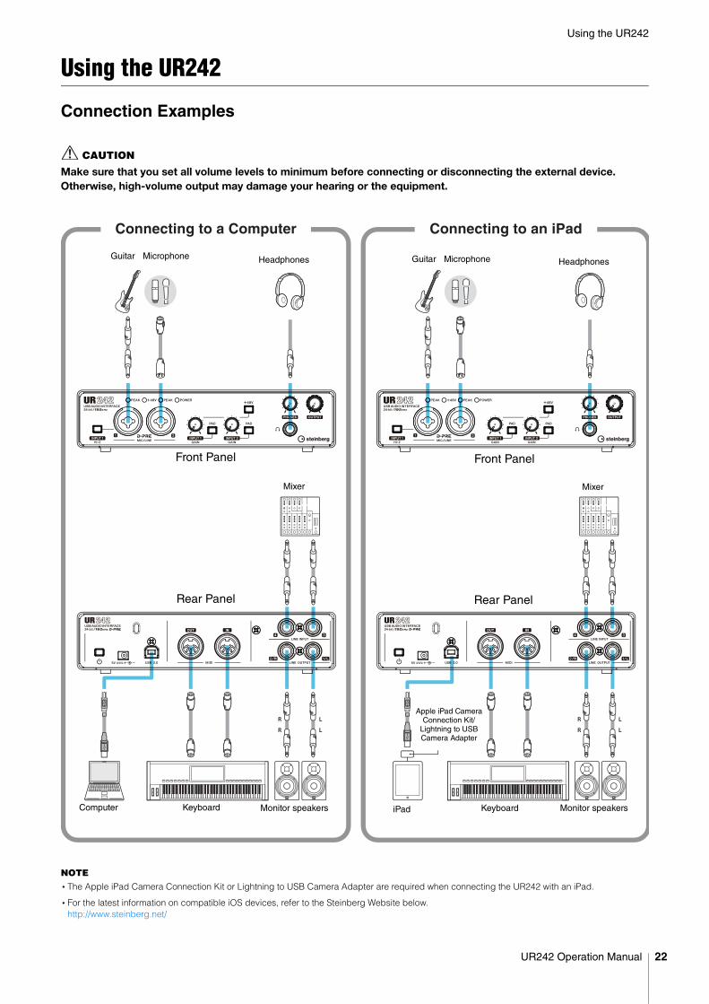
Connection Examples
CAUTION
Make sure that you set all volume levels to minimum before connecting or disconnecting the external device. Otherwise, high-volume output may damage your hearing or the equipment.
NOTE•The Apple iPad Camera Connection Kit or Lightning to USB Camera Adapter are required when connecting the UR242 with an iPad.
•For the latest information on compatible iOS devices, refer to the Steinberg Website below.http://www.steinberg.net/
Connecting to a Computer Connecting to an iPad
HeadphonesGuitar Microphone
Monitor speakersComputer
Front Panel
Rear Panel
HeadphonesGuitar Microphone
Front Panel
Rear Panel
MixerMixer
Monitor speakersKeyboard KeyboardiPad
Apple iPad Camera Connection Kit/
Lightning to USB Camera Adapter
UR242 Operation Manual 22
Using the UR242
Configuring Audio Driver Settings on the DAW Software
Cubase Series Programs
1. Make sure that all applications have been closed.
2. Make sure that the [ ] switch has been turned on (O).
3. Launch the Cubase series DAW.
4. When the [ASIO Driver Setup] window appears while the Cubase series program is launching, confirm that the device is selected, then click [OK].
The audio driver settings are now complete.
Programs other than Cubase Series
1. Make sure that all applications have been closed.
2. Make sure that the [ ] switch has been turned on (O).
3. Launch the DAW software.
4. Open the audio interface settings window.
5. (Windows only) Select the ASIO Driver for the audio driver settings.
6. Set the ASIO Driver for Windows and audio interface for Mac as follows.
Windows
Set the ASIO Driver settings to [Yamaha Steinberg USB ASIO].
Mac
Set the UR242 to the appropriate audio interface settings.
The audio driver settings are now complete.
Recording/PlaybackConnect a microphone as shown in the connection examples (page 22). Turn the [+48V] switch on when using a phantom powered condenser microphone.
Cubase Series Programs
1. Launch the Cubase series DAW.The [steinberg hub] window appears.
2. Select the project template [Steinberg UR242 Vocal-Inst Recording 1-C7] in [Recording] on the [steinberg hub] window, then click [Create].
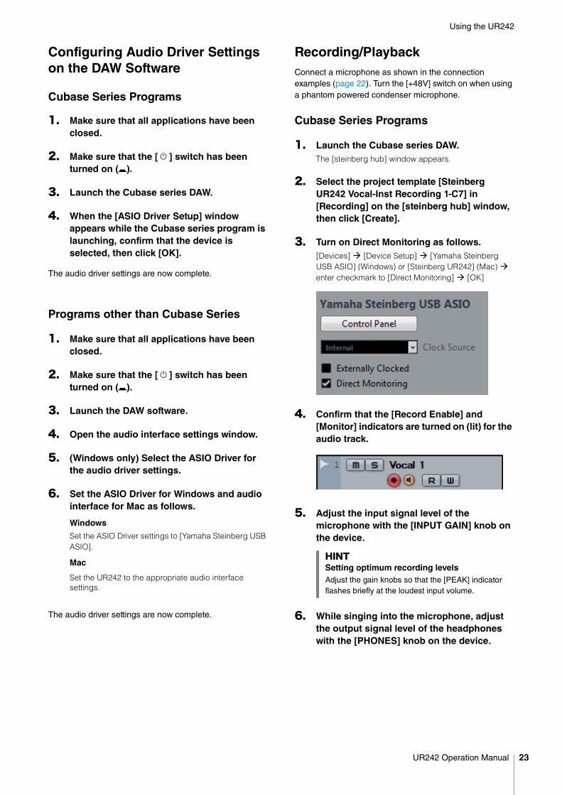
3. Turn on Direct Monitoring as follows. [Devices] [Device Setup] [Yamaha Steinberg USB ASIO] (Windows) or [Steinberg UR242] (Mac) enter checkmark to [Direct Monitoring] [OK]
4. Confirm that the [Record Enable] and [Monitor] indicators are turned on (lit) for the audio track.
5. Adjust the input signal level of the microphone with the [INPUT GAIN] knob on the device.
6. While singing into the microphone, adjust the output signal level of the headphones with the [PHONES] knob on the device.
HINTSetting optimum recording levelsAdjust the gain knobs so that the [PEAK] indicator flashes briefly at the loudest input volume.
UR242 Operation Manual 23
Using the UR242
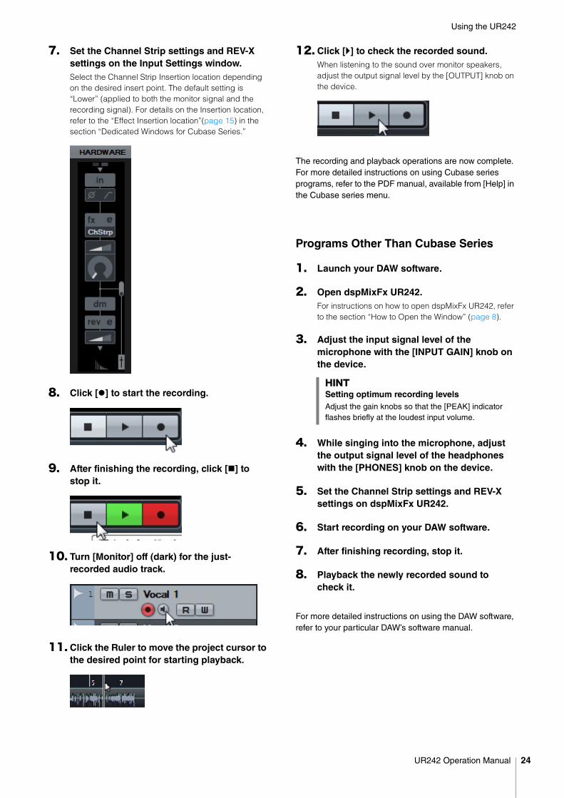
7. Set the Channel Strip settings and REV-X settings on the Input Settings window.Select the Channel Strip Insertion location depending on the desired insert point. The default setting is “Lower” (applied to both the monitor signal and the recording signal). For details on the Insertion location, refer to the “Effect Insertion location”(page 15) in the section “Dedicated Windows for Cubase Series.”
8. Click [] to start the recording.
9. After finishing the recording, click [] to stop it.
10. Turn [Monitor] off (dark) for the just-recorded audio track.
11. Click the Ruler to move the project cursor to the desired point for starting playback.
12. Click [] to check the recorded sound.When listening to the sound over monitor speakers, adjust the output signal level by the [OUTPUT] knob on the device.
The recording and playback operations are now complete. For more detailed instructions on using Cubase series programs, refer to the PDF manual, available from [Help] in the Cubase series menu.
Programs Other Than Cubase Series
1. Launch your DAW software.
2. Open dspMixFx UR242.For instructions on how to open dspMixFx UR242, refer to the section “How to Open the Window” (page 8).
3. Adjust the input signal level of the microphone with the [INPUT GAIN] knob on the device.
4. While singing into the microphone, adjust the output signal level of the headphones with the [PHONES] knob on the device.
5. Set the Channel Strip settings and REV-X settings on dspMixFx UR242.
6. Start recording on your DAW software.
7. After finishing recording, stop it.
8. Playback the newly recorded sound to check it.
For more detailed instructions on using the DAW software, refer to your particular DAW’s software manual.
HINTSetting optimum recording levelsAdjust the gain knobs so that the [PEAK] indicator flashes briefly at the loudest input volume.
UR242 Operation Manual 24
Troubleshooting
Troubleshooting
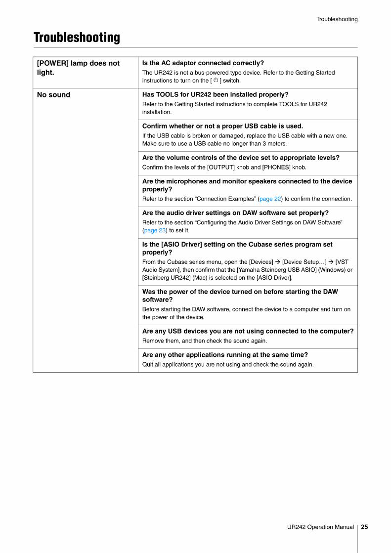
[POWER] lamp does not light.
Is the AC adaptor connected correctly? The UR242 is not a bus-powered type device. Refer to the Getting Started instructions to turn on the [ ] switch.
No sound Has TOOLS for UR242 been installed properly? Refer to the Getting Started instructions to complete TOOLS for UR242 installation.
Confirm whether or not a proper USB cable is used.If the USB cable is broken or damaged, replace the USB cable with a new one. Make sure to use a USB cable no longer than 3 meters.
Are the volume controls of the device set to appropriate levels?Confirm the levels of the [OUTPUT] knob and [PHONES] knob.
Are the microphones and monitor speakers connected to the device properly?Refer to the section “Connection Examples” (page 22) to confirm the connection.
Are the audio driver settings on DAW software set properly? Refer to the section “Configuring the Audio Driver Settings on DAW Software” (page 23) to set it.
Is the [ASIO Driver] setting on the Cubase series program set properly?From the Cubase series menu, open the [Devices] [Device Setup…] [VST Audio System], then confirm that the [Yamaha Steinberg USB ASIO] (Windows) or [Steinberg UR242] (Mac) is selected on the [ASIO Driver].
Was the power of the device turned on before starting the DAW software?Before starting the DAW software, connect the device to a computer and turn on the power of the device.
Are any USB devices you are not using connected to the computer?Remove them, and then check the sound again.
Are any other applications running at the same time?Quit all applications you are not using and check the sound again.
UR242 Operation Manual 25
Troubleshooting
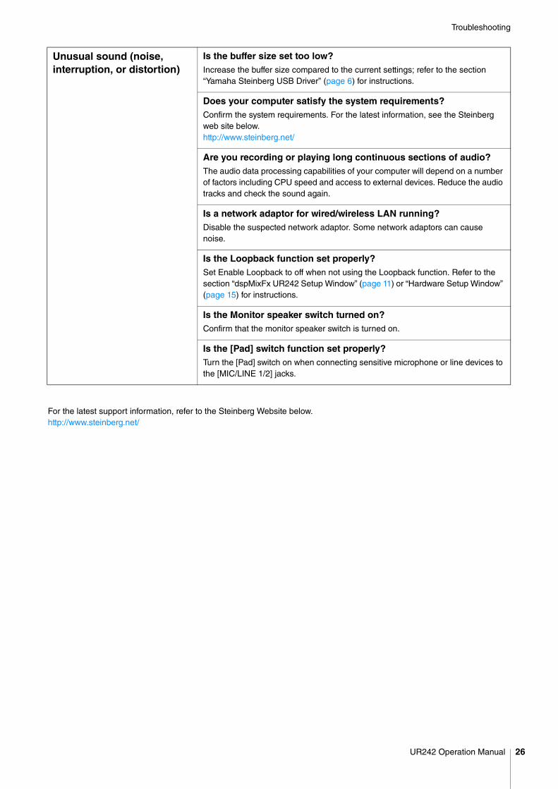
For the latest support information, refer to the Steinberg Website below.http://www.steinberg.net/
Unusual sound (noise,interruption, or distortion)
Is the buffer size set too low?Increase the buffer size compared to the current settings; refer to the section “Yamaha Steinberg USB Driver” (page 6) for instructions.
Does your computer satisfy the system requirements?Confirm the system requirements. For the latest information, see the Steinberg web site below.http://www.steinberg.net/
Are you recording or playing long continuous sections of audio?The audio data processing capabilities of your computer will depend on a number of factors including CPU speed and access to external devices. Reduce the audio tracks and check the sound again.
Is a network adaptor for wired/wireless LAN running?Disable the suspected network adaptor. Some network adaptors can cause noise.
Is the Loopback function set properly?Set Enable Loopback to off when not using the Loopback function. Refer to the section “dspMixFx UR242 Setup Window” (page 11) or “Hardware Setup Window” (page 15) for instructions.
Is the Monitor speaker switch turned on?Confirm that the monitor speaker switch is turned on.
Is the [Pad] switch function set properly?Turn the [Pad] switch on when connecting sensitive microphone or line devices to the [MIC/LINE 1/2] jacks.
UR242 Operation Manual 26
Appendix
Appendix
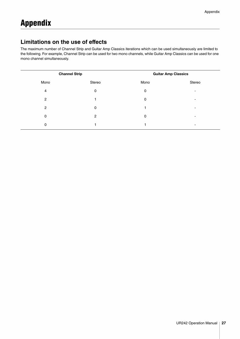
Limitations on the use of effectsThe maximum number of Channel Strip and Guitar Amp Classics iterations which can be used simultaneously are limited to the following. For example, Channel Strip can be used for two mono channels, while Guitar Amp Classics can be used for one mono channel simultaneously.
Channel Strip Guitar Amp Classics
Mono Stereo Mono Stereo
4 0 0 -
2 1 0 -
2 0 1 -
0 2 0 -
0 1 1 -
UR242 Operation Manual 27
Appendix
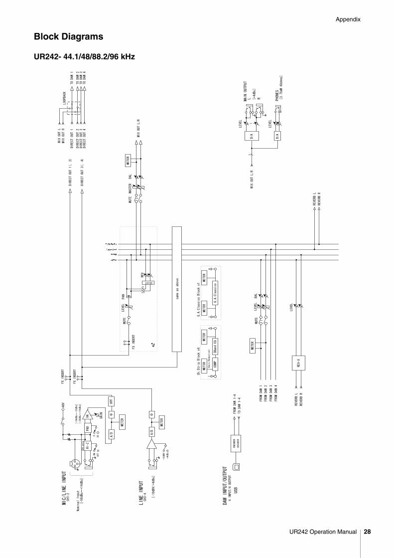
Block Diagrams
UR242- 44.1/48/88.2/96 kHz
UR242 Operation Manual 28
Appendix
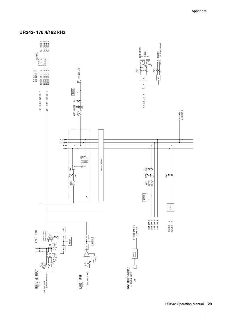
UR242- 176.4/192 kHz
UR242 Operation Manual 29
Appendix
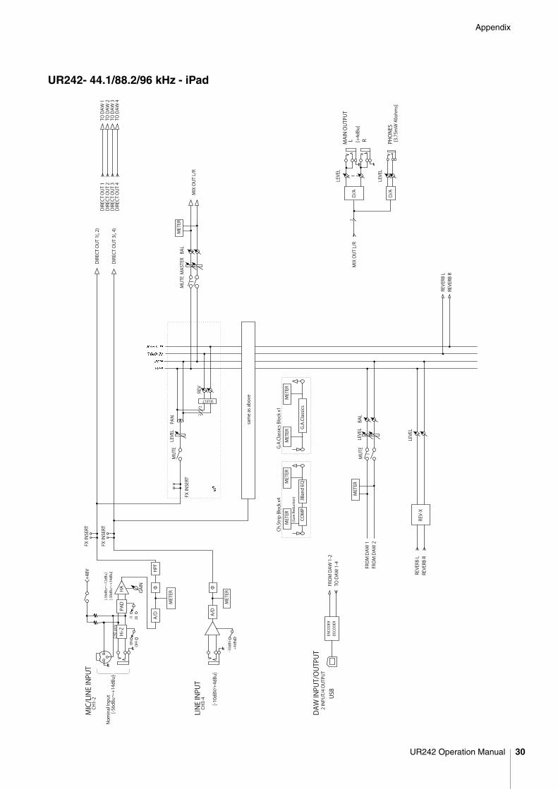
UR242- 44.1/88.2/96 kHz - iPad
MUTELEVELPAN
MUTE
LEVELBAL
METER
LEVEL
REV-X
REVERB L
REVERB R
REV
SELECT
22
DIRECT OUT 3(, 4)
USB
ENCODER
DECODER
FROM DAW 1-2
TO DAW 1-4
DAW INPUT/OUTPUT
2 INPUT/4 OUTPUT
FROM DAW 1
FROM DAW 2
METER
MUTE
BAL
MASTER
MIX OUT L/R
PHONES
[3.75mW 40ohms]
D/A
LEVEL
LEVEL
D/A
[+4dBu]
RMAIN OUTPUT
L
REVERB L
REVERB R
MIX OUT L/R
2
FX INSERT
METER
3Band EQ
COMP
(Gain Reduction)
Ch.Strip Block x4
METER
DIRECT OUT 1
DIRECT OUT 2
DIRECT OUT 3
DIRECT OUT 4
TO DAW 1
TO DAW 2
TO DAW 3
TO DAW 4
G.A.Classics Block x1
METER
METER
G.A.Classics
A/D
Φ
METER
LINE INPUT
CH3-4
[-10dBV/+4dBu]
-10dBV
+4dBu
HA
MIC/LINE INPUT
CH1-2
GAIN
[-30dBu~+14dBu]
[-56dBu~-12dBu]
A/D
HPF
Φ
0 26
PAD
+48V
Hi-Z
ON OFF
CH2 only
[-56dBu~+14dBu]
METER
Nominal Input
DIRECT OUT 1(, 2)
same as above
FX INSERT
FX INSERT
UR242 Operation Manual 30
Appendix
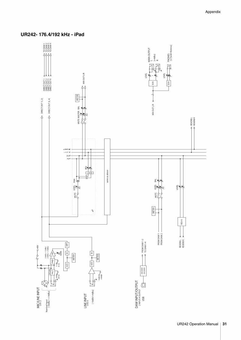
UR242- 176.4/192 kHz - iPad
MUTELEVELPAN
MUTE
LEVELBAL
METER
LEVEL
REV-X
REVERB L
REVERB R
REV
SELECT
22
DIRECT OUT 3(, 4)
USB
ENCODER
DECODER
FROM DAW 1-2
TO DAW 1-4
DAW INPUT/OUTPUT
2 INPUT/4 OUTPUT
FROM DAW 1
FROM DAW 2
METER
MUTE
BAL
MASTER
MIX OUT L/R
PHONES
[3.75mW 40ohms]
D/A
LEVEL
LEVEL
D/A
[+4dBu]
RMAIN OUTPUT
L
REVERB L
REVERB R
MIX OUT L/R
2
A/D
Φ
METER
LINE INPUT
CH3-4
[-10dBV/+4dBu]
-10dBV
+4dBu
HA
MIC/LINE INPUT
CH1-2
GAIN
[-30dBu~+14dBu]
[-56dBu~-12dBu]
A/D
HPF
Φ
0 26
PAD
+48V
Hi-Z
ON OFF
CH2 only
[-56dBu~+14dBu]
METER
Nominal Input
DIRECT OUT 1(, 2)
same as above
DIRECT OUT 1
DIRECT OUT 2
DIRECT OUT 3
DIRECT OUT 4
TO DAW 1
TO DAW 2
TO DAW 3
TO DAW 4
UR242 Operation Manual 31

Steinberg Websitehttp://www.steinberg.net/
Manual Development Department© 2015 Yamaha Corporation
Published 1/2015 发行 MWA0


