42
USB Documentation Christopher D. Leary and Devrin Talen December 17, 2007
USB Documentation
Christopher D. Leary and Devrin Talen
December 17, 2007

Contents
1 Universal Serial Bus 31.1 Introduction . . . . . . . . . . . . . . . . . . . . . . . . . . . . . . 41.2 USB Topology . . . . . . . . . . . . . . . . . . . . . . . . . . . . 41.3 Logical Protocol . . . . . . . . . . . . . . . . . . . . . . . . . . . 5
1.3.1 Control Transfer Grammar . . . . . . . . . . . . . . . . . 71.4 Physical Protocol . . . . . . . . . . . . . . . . . . . . . . . . . . . 8
1.4.1 Signaling . . . . . . . . . . . . . . . . . . . . . . . . . . . 81.4.2 Differential Encoding . . . . . . . . . . . . . . . . . . . . . 81.4.3 Idle States . . . . . . . . . . . . . . . . . . . . . . . . . . . 81.4.4 NRZI Encoding . . . . . . . . . . . . . . . . . . . . . . . . 91.4.5 Bit Stuffing . . . . . . . . . . . . . . . . . . . . . . . . . . 91.4.6 Special Signals . . . . . . . . . . . . . . . . . . . . . . . . 91.4.7 Frames . . . . . . . . . . . . . . . . . . . . . . . . . . . . 10
1.5 Bus Enumeration . . . . . . . . . . . . . . . . . . . . . . . . . . . 101.5.1 Device States . . . . . . . . . . . . . . . . . . . . . . . . . 10
2 Host Controller Interface 122.1 API Overview . . . . . . . . . . . . . . . . . . . . . . . . . . . . . 132.2 Descriptors . . . . . . . . . . . . . . . . . . . . . . . . . . . . . . 13
2.2.1 Endpoint Descriptor . . . . . . . . . . . . . . . . . . . . . 132.2.2 Stage Descriptor . . . . . . . . . . . . . . . . . . . . . . . 14
2.3 Asynchronous I/O . . . . . . . . . . . . . . . . . . . . . . . . . . 152.4 USB Driver . . . . . . . . . . . . . . . . . . . . . . . . . . . . . . 152.5 Host Controller Driver . . . . . . . . . . . . . . . . . . . . . . . . 162.6 Host Controller . . . . . . . . . . . . . . . . . . . . . . . . . . . . 18
2.6.1 Finding Stages . . . . . . . . . . . . . . . . . . . . . . . . 182.6.2 Performing Stages . . . . . . . . . . . . . . . . . . . . . . 192.6.3 Reporting Results . . . . . . . . . . . . . . . . . . . . . . 19
2.7 Limitations . . . . . . . . . . . . . . . . . . . . . . . . . . . . . . 192.7.1 Low Speed Operation . . . . . . . . . . . . . . . . . . . . 192.7.2 CRC Verification . . . . . . . . . . . . . . . . . . . . . . . 20
2.8 Future Improvements . . . . . . . . . . . . . . . . . . . . . . . . . 202.8.1 Hardware Assistance . . . . . . . . . . . . . . . . . . . . . 202.8.2 Power Requirements . . . . . . . . . . . . . . . . . . . . . 21
1

3 Using SIAM32 223.1 Introduction . . . . . . . . . . . . . . . . . . . . . . . . . . . . . . 233.2 Transition to Asynchronous Callbacks . . . . . . . . . . . . . . . 23
3.2.1 Callbacks Explained . . . . . . . . . . . . . . . . . . . . . 233.2.2 Main loop . . . . . . . . . . . . . . . . . . . . . . . . . . . 23
3.3 Define Statements . . . . . . . . . . . . . . . . . . . . . . . . . . 243.4 USB Hardware . . . . . . . . . . . . . . . . . . . . . . . . . . . . 25
4 Serial Interface Engine 264.1 Introduction . . . . . . . . . . . . . . . . . . . . . . . . . . . . . . 274.2 Design . . . . . . . . . . . . . . . . . . . . . . . . . . . . . . . . . 27
4.2.1 Software Interface . . . . . . . . . . . . . . . . . . . . . . 274.2.2 Token & Data Buffers . . . . . . . . . . . . . . . . . . . . 274.2.3 Token & Data Packet Length . . . . . . . . . . . . . . . . 284.2.4 Handshake result . . . . . . . . . . . . . . . . . . . . . . . 294.2.5 Data direction . . . . . . . . . . . . . . . . . . . . . . . . 294.2.6 Data encoding . . . . . . . . . . . . . . . . . . . . . . . . 29
4.3 Implementation . . . . . . . . . . . . . . . . . . . . . . . . . . . . 294.3.1 Transmitting a packet . . . . . . . . . . . . . . . . . . . . 30
5 Hardware 355.1 Introduction . . . . . . . . . . . . . . . . . . . . . . . . . . . . . . 365.2 Design . . . . . . . . . . . . . . . . . . . . . . . . . . . . . . . . . 36
5.2.1 Encoding the output . . . . . . . . . . . . . . . . . . . . . 365.2.2 Transmit and receive . . . . . . . . . . . . . . . . . . . . . 375.2.3 Port configuration . . . . . . . . . . . . . . . . . . . . . . 375.2.4 USB timing considerations . . . . . . . . . . . . . . . . . 38
A Acknowledgments 40
2

Chapter 1
Universal Serial Bus
3

1.1 Introduction
The Universal Serial Bus (USB) protocol is designed to enable communicationbetween many devices by sharing a data bus. The USB specification calls forone of these devices to be a USB Host, which interfaces with the bus via acomponent called the USB Host Controller. Other devices respond to requestsfrom the USB Host, and cannot initiate traffic on their own.
This documentation offers an abridged overview of the USB 2.0 Specificationas it pertains to the low speed capabilities of a USB Host Controller. The lowspeed USB protocol is primarily intended for interactive devices with data ratesranging from 10 to 100kbps.
1.2 USB Topology
A USB system consists of one host and many devices. A function is a logicalpart of a device. For example, a multipurpose printer may have many functions:printer, scanner, etc; however, a mouse typically has just one function whichrepresents its whole state. Many devices can be connected to a single host con-troller by using USB hubs, with each function within each device acknowledgedas a separate entity. Figure 1.1 gives a general overview of a USB system.
Host Controller
USB Hub
Mouse USB Hub
External
Drive
External
Drive
Keyboard
Figure 1.1: Example USB topology
USB devices are recognized as both physical and logical components. Thestructure is defined as follows:
4

Device The physical device that has a single USB connection. This can eitherplug into a USB hub or directly into the host. Examples are familiar:mice, keyboards, printers, etc.
Function As explained above, a USB device may have more than one function.A web camera may have multiple functions; for example, one camerafunction and one microphone function. A function is constituted by oneor more endpoints.
Endpoint An endpoint is a point of transfer for a function. The USB hostestablishes connections between its endpoints and a function’s endpointsin order to perform transfers to and from the function. Different endpointswithin a function typically represent different types of transfers, which arediscussed below.
Hubs are unsupported by the low speed USB protocol; they will be ignoredfor the remainder of this document.
1.3 Logical Protocol
Data transfer over USB is initiated by the host controller. USB low speedprotocol includes the following types of transfers:
Control Transfer Used to perform setup and non-data tasks, such as assigninga device to an address or reading information on the device capabilities.Control transfers don’t occur at regular intervals – this is the behavior ofinterrupt transfers (below).
Interrupt Transfer Used for periodic endpoint polling. The polling intervalis requested by the function and carried out by the host controller. Aninterrupt transfer can either be used to send data to the device or to receivedata from it. Once the host controller has established a connection to aninterrupt endpoint, interrupt endpoint polling continues indefinitely (untilthe device is no longer present).
A transfer is subdivided into one or more stages. An interrupt transferonly has one stage: a data stage (in either the transmit or receive direction). Acontrol transfer is broken up into the following stages:
Setup Stage Informs the device of the type of control transfer that is aboutto occur; i.e. if the device should prepare to receive data, what datathe device should return to the host controller, etc. Keep in mind thatall control transfers are initiated by the USB host, so the setup stage isalways in the transmission direction.
Data Stage This stage is used to transfer data to/from the device. Thoughthis stage will be used in almost all transfers, it is optional.
5

Status Stage Acknowledges via a handshake. If the host controller sent data,it will ask the device to acknowledge that the data was received correctly.Likewise, if the host controller received data, it will inform the device thatthe data was received correctly.
A stage is subdivided into one or more transactions. A transaction can bethought of as an atomic operation on a USB line — when a transaction is beingperformed it will not be interrupted until it completes if the protocol is followed.The structure of a transaction is discussed below and is shown in Figure 1.2.
Token Packet This is the first piece of information, and is always sent by thehost controller. The token packet informs the device of whether it shouldbe sending the data packet or receiving it.
Data Packet Either sent by the device or the host controller. The data packetis of variable length.
Handshake Packet If the host controller sent the data packet, it will wait fora handshake packet from the device. If the device sent the data packet, itwill wait for a handshake packet from the host controller.
See Figure 1.3 for clarification.
Figure 1.2: USB transaction structure
Figure 1.3: Packet ordering
6

1.3.1 Control Transfer Grammar
Grammars are often useful to clarify ambiguities.1 The following grammar de-fines the logical structure of USB communication for control transfers. Thoughnot explicitly mentioned, packets consist of several concatenated fields, the firstof which is a packet identifier, abbreviated as PID in the below.
Transfer Subtypes
<control-transfer> ::= <control-write> | <control-read> | <control-no-data>
<control-write> ::= <setup-stage> <data-out-stage> <status-in-stage>
<control-read> ::= <setup-stage> <data-in-stage> <status-out-stage>
<control-no-data> ::= <setup-stage> <status-in-stage>
Stages
<setup-stage> ::= <setup-transaction>
<data-out-stage ::= <data-out-transaction>*
<data-in-stage ::= <data-in-transaction>*
<status-in-stage> ::= <status-in-transaction>
<status-out-stage> ::= <status-out-transaction>
Transactions
Notably, all data transactions that take place with respect to an endpoint requirethat that data PID be toggled from Data0 PID to Data1 PID on successfultransfer.2
<setup-transaction> ::= <setup-token-packet> <data-0-packet> <opt-handshake>
<data-out-transaction> ::= <out-token-packet> <data-packet> <opt-handshake>
<data-in-transaction> ::= <in-token-packet> <data-packet> <opt-handshake>
<status-in-transaction> ::= <in-token-packet> <data-1-packet> <opt-handshake>
<status-out-transaction> ::= <out-token-packet> <zero-len-data-1-packet> <opt-handshake>
Packets
<token-packet> ::= <setup-token-packet> | <out-token-packet> | <in-token-packet>
<setup-token-packet> ::= <setup-pid> <address> <endpoint-number> <crc5>
<out-token-packet> ::= <out-pid> <address> <endpoint-number> <crc5>
<in-token-packet> ::= <in-pid> <address> <endpoint-number> <crc5>
<data-packet> ::= <data-0-packet> | <data-1-packet>
<data-0-packet> ::= <data-0-pid> <payload> <crc16>
<data-1-packet> ::= <data-1-pid> <payload> <crc16>
<handshake> ::= <ack-pid> | <nak-pid> | <stall-pid>
1Though, ironically, determining whether or not an (arbitrary) grammar is ambiguous is aprovably undecidable problem.
2Further information can be found in section 8.6 of the USB2.0 Specification
7

1.4 Physical Protocol
1.4.1 Signaling
USB low speed is defined as 1.5 Mb/s. Individual bits are held for 666 ns,determined by:
11.5× 106
= 666× 10−9 s
For example, in Figure 1.4 the width of an individual bit is 666 ns.
1.4.2 Differential Encoding
USB communication travels on two of the lines on the USB cable: the D+ andD- lines. Bits are differentially encoded; see Table 1.1 for an overview of linestates and Figure 1.4 for an example of bus traffic.
D+ D- State Meaning0 0 SE0 Single-ended 0.0 1 J Differential 0.1 0 K Differential 1.1 1 SE1 Single-ended 1; illegal bus state.
Table 1.1: Differential encoding for low speed
For low speed communication a differential 0 is also called a “J” state, anda differential 1 is called a “K” state.
1.4.3 Idle States
A low speed device will use a pull-up network on the D- line. The effect of thisis a J state on the bus in cases where the lines are not being driven and a lowspeed device is attached. See Figure 1.4 for an idea of what USB communicationwith a low speed device may look like. In the figure, the signals begin in theidle J state and a sequence of bits are subsequently signaled.
-
Time
D+
D-
0 0 1 0 1 0 1 0 1 1 0
Figure 1.4: Example of bus communication
8
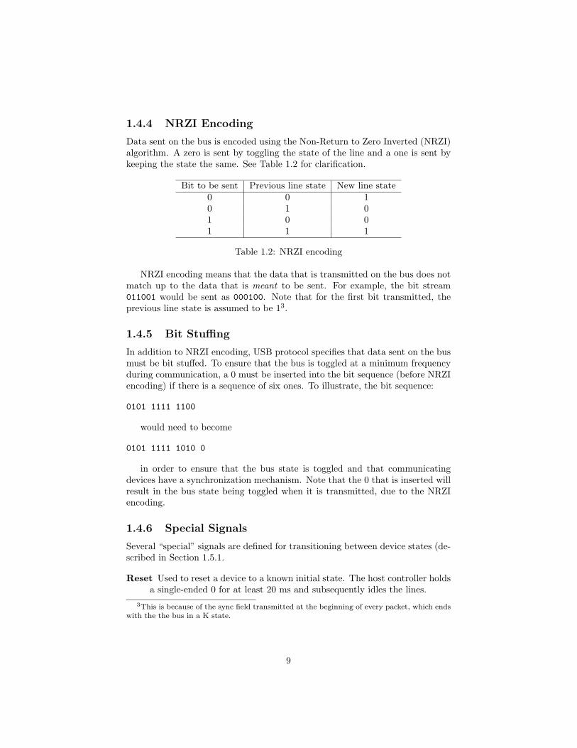
1.4.4 NRZI Encoding
Data sent on the bus is encoded using the Non-Return to Zero Inverted (NRZI)algorithm. A zero is sent by toggling the state of the line and a one is sent bykeeping the state the same. See Table 1.2 for clarification.
Bit to be sent Previous line state New line state0 0 10 1 01 0 01 1 1
Table 1.2: NRZI encoding
NRZI encoding means that the data that is transmitted on the bus does notmatch up to the data that is meant to be sent. For example, the bit stream011001 would be sent as 000100. Note that for the first bit transmitted, theprevious line state is assumed to be 13.
1.4.5 Bit Stuffing
In addition to NRZI encoding, USB protocol specifies that data sent on the busmust be bit stuffed. To ensure that the bus is toggled at a minimum frequencyduring communication, a 0 must be inserted into the bit sequence (before NRZIencoding) if there is a sequence of six ones. To illustrate, the bit sequence:
0101 1111 1100
would need to become
0101 1111 1010 0
in order to ensure that the bus state is toggled and that communicatingdevices have a synchronization mechanism. Note that the 0 that is inserted willresult in the bus state being toggled when it is transmitted, due to the NRZIencoding.
1.4.6 Special Signals
Several “special” signals are defined for transitioning between device states (de-scribed in Section 1.5.1.
Reset Used to reset a device to a known initial state. The host controller holdsa single-ended 0 for at least 20 ms and subsequently idles the lines.
3This is because of the sync field transmitted at the beginning of every packet, which endswith the the bus in a K state.
9
Resume If a device is in a “suspended” state, this signal is used to wake adevice without resetting it. A differential 1 is held for 20 ms. An end-of-packet (EOP) is then sent, after which the lines are idled. Devices enterthe suspend state after 3ms of no bus activity; i.e. if the host controllerneglects to send a keep alive signal at the start of every frame.
End of Packet Used both after a packet has been transmitted and at the endof a resume signal. Signaled by two USB bit-times of a single-ended 0,followed by one bit-time of a J state (differential 0).
1.4.7 Frames
USB traffic is divided into frames, one frame being equal to one millisecond. Atthe start of a frame the host controller must send a keep alive signal to eachdevice to prevent devices from going into the suspend state. Within a frame,the host controller must dedicate enough time to interrupt transfers to poll allof the endpoints with interrupt transfers. After that, the host controller usesthe remaining time to perform control transfers.
1.5 Bus Enumeration
When the host controller detects a J state driven on the bus, it assumes that aUSB device has been plugged in. The host controller then executes the followingsteps:
1. Host waits for at least 100 ms to account for the insertion process.
2. Host resets the device. Device should now be at address 0 and the defaultcontrol pipe will be open (default state).
3. Host queries the device descriptor from the devices default control pipe.
4. The host controller assigns a unique address to the device.
5. Host queries all configuration descriptors from the device, then sets one.At this point, the device will begin to draw the amount of power requestedby the assigned interface.
6. Host queries all other remaining descriptors (interface, endpoint, etc.) andsets up any requested interrupt transfers.
1.5.1 Device States
The externally visible states for a device (those states that are recognized bythe host controller) are enumerated in the following:
Attached Device is attached to the bus, but is only powered with the defaultamount of power.
10
Powered After the USB host analyzes the power requirements for the device(which it queries through “Get Configuration Requests”), it determineswhich configuration it can satisfy power requirements for. The host setsthe satisfiable configuration for the device (through a “Set ConfigurationRequest”), and provides the necessary amount of power to the device.With all these steps completed, the device enters powered state. In thepowered state, the device must be reset to enter the default state.
Suspended After being powered, a device may enter the suspended state afterthree milliseconds of bus inactivity. The device’s function cannot be usedin this state, and it must be resumed into the previous state (the state ofthe device before suspension).
Default After being attached and powered, but before being configured, thedevice will only respond via its default endpoint at address zero.
Address Device has been assigned a unique address. Will respond on thedefault endpoint at its assigned address.
Configured Host has assigned a configuration to the device. The default end-point is still addressable, but now any endpoints specified by the assignedconfiguration are available as well.
11
Chapter 2
Host Controller Interface
12
2.1 API Overview
Our code base roughly follows the Open Host Controller Interface (OHCI) Spec-ification. We chose to implement this standard both to take advantage of thevenerable code structure and to assist in the design process. As such, our HostController API follows naturally from the specification, but offers some conve-nient higher-level functionality in addition.
2.2 Descriptors
The OHCI specification relies heavily on the notion of descriptors. A descriptoris an object that describes the state and capabilities of an endpoint, device,transfer, etc. While the USB specification already defines standard descriptorsfor devices, configurations, and endpoints, etc., the OHCI specification definestwo descriptors that are used only by the host controller driver. These areexplained below:
2.2.1 Endpoint Descriptor
An endpoint descriptor has the following fields:
Function Address The USB address of the device with the endpoint describedby this descriptor.
Endpoint Number The number of the endpoint within the device.
Direction Describes the direction of the endpoint. This can be one of threevalues: IN or OUT, or the direction can be determined by the token packetPID of the transaction being executed. The latter is generally the case forcontrol endpoints, while the former is the usually the case for interruptendpoints.
Speed An endpoint can be full- or low-speed.
Skip A flag to be set if the host controller driver should ignore processing thisendpoint when executing stage descriptors.
Format Set to 0, unless the endpoint is isochronous, in which case this field isset to 1.
Halted Set by the host controller when an error in processing a stage descriptoroccurs on this endpoint.
Toggle Carry Contains the last data toggle value from a retired stage descrip-tor.
Head Pointer Points to the first stage descriptor queued to this endpoint de-scriptor.
13

Tail Pointer Points to the last stage descriptor that is queued on this endpointdescriptor.
Next Endpoint Points to the next endpoint descriptor in the linked list.
The following fields were added to our implementation to simplify the struc-ture of the host controller:
Interrupt Interval Rather than creating an entire binary tree to store inter-rupt endpoint descriptors, we use a separate linked list. This field is usedto determine how often to execute the stage descriptor attached to aninterrupt endpoint descriptor, rather than using the depth of the binarytree.
2.2.2 Stage Descriptor
A stage descriptor describes one or more transactions that need to be processedtogether. For example, as discussed in Section 1.3, a control transfer is made ofthree stages: a setup stage, data stage, and status stage. Each of these stagesis queued to the appropriate control endpoint, where they will be processed bythe host controller. What follows is a description of each of the fields within astage descriptor:
Buffer Rounding If this field is set to 0, then the last data packet receivedfrom an endpoint must exactly fill the data buffer. If set to 1, then thelast data packet received by an endpoint may be shorter than the bufferand not cause an error.
Direction A combination of the direction that data flows and the PID of thetransactions within the stage. This can be OUT, IN, or SETUP. This PIDis applied to the token packet of the transactions.
Our implementation also defines a STATUS PID, which is used in a specialcase for the status stage of a control transfer.
Data Toggle This field determines the DATA0/1 PID of any data packetswithin the stage. This can also be set to toggle in accordance to theToggle Carry field of the endpoint descriptor this stage is associated with.
Error Count Incremented each time there is a transmission error (i.e. mal-formed CRC, etc.). If this count reaches 3 the error code is recorded andthe stage is retired to the done queue.
Condition Code Contains the status of the last completed transaction withinthe stage.
Our implementation has also added;
Buffer Pointer to the data payload either to be transmitted or received by thehost controller. If this payload is larger than the maximum packet size ofthe device it will be broken into multiple transactions and sent in pieces.
14

Buffer Bit Count Total size (in bits) of the allocated buffer.
2.3 Asynchronous I/O
The high level API interface uses an asynchronous I/O mechanism. Whensubmitting an I/O request an object is immediately returned that represents afuture result — this representation is appropriately called a Deffered.1
When a Deferred is returned, one can add a series of callbacks to it. Acallback is a function that is passed by reference and called at some later time.Callbacks are added in chains to a deferred, so that when all I/O has completedthe result (e.g., a data buffer) is passed into the first callback in the chain. Thefirst callback in the chain passes its return value to the second callback in thechain, and so on.
Because callbacks are an efficient and straightforward mechanism for im-plementing deferreds, there is also a mechanism for handling errors in callbackchains, which we term “errbacks”. Errbacks may be used in conjunction withcallbacks in order to handle all kinds of I/O result processing scenarios.
In order to perform correct memory management, there is also a specialDeferred deletion mechanism that the API implements, as demonstrated in thefollowing:
deferred_t deferred = usb_driver_submit_request(...);deferred_add_callback(deferred, &good_result_func);deferred_add_errback(deferred, &bad_result_func);deferred_add_callback(deferred, &next_good_result_func);deferred_add_both(deferred, DEFERRED_DELETE);
The deferred_add_both acts as a kind of “finally” mechanism that acts inboth the callback and errback chain to ensure the deferred deletion occurs viathe special DEFERRED_DELETE construct provided. Note that function referencesmay also be added via the deferred_add_both method.
2.4 USB Driver
The USB Driver exists as the sole member of the USB Function layer — therest of the functionality at the USB Function layer level is implemented by thelibrary user. The USB Driver acts as a main-loop mechanism for USB devicecommunication that allows for user functionality injection.
The USB Driver is initialized with a user function which is called as the USBDriver’s main loop iterates. The main loop is initiated by usb_driver_run, andcalls the user function dynamically — in other words, it can be changed duringruntime using usb_driver_set_user_function, allowing for a good deal offlexibility. The most common manner of using this user function is as some
1The deferred mechanism implemented was inspired by the Twisted Python framework:http://twistedmatrix.com
15

form of state machine that enqueues requests for the USB system and handlesthe results via callbacks chained onto Deferreds.
The user specifies the frequency of two parameters in running the USBDriver’s main loop: control stages per main loop iteration and iterations perdone queue cleaning. Adjusting these parameters should allow the user to ap-propriately configure the frequency with which the user function is called.
2.5 Host Controller Driver
The host controller driver is the bridge between the client software and thehost controller (see Figure 2.1). The host controller driver is responsible forenumerating new devices attached to the bus, and scheduling and executingtransactions. A linked list of control and interrupt endpoints2 is created andmodified as devices are connected/disconnected from the bus. The host con-troller driver schedules transactions by attaching a descriptor to the appropriatecontrol or interrupt endpoint.
Note that unlike the implementation described by the OHCI, the host con-troller driver of this project must be controlled by the USB client software.There are no interrupts defined within the code to handle frames or schedulingstages — these tasks must be initiated by the client software. This decision wasmade partly to simplify the program structure, but mostly to give the clientsoftware the most control over the host controller driver. If the client softwarehas a large computation to process, the host controller is able to respect thatand does not need to operate every frame.
Host Controller
USB Device
Client Software
Host Controller Driver
OHCI
Figure 2.1: Open Host Controller overview
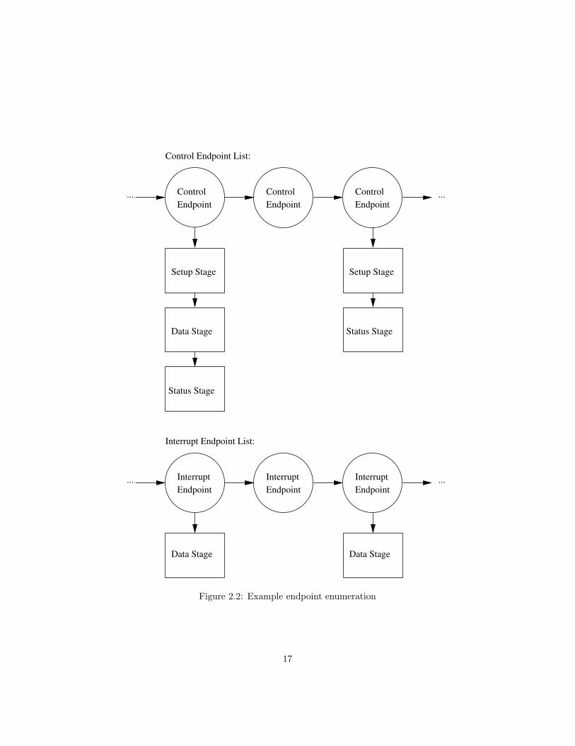
Every frame the host controller driver “walks” the list and executes stagesin the order in which they are queued on the endpoint descriptor. For example,Figure 2.2 shows an example setup. There are three control endpoints and threeinterrupt endpoints enumerated.
The leftmost control endpoint descriptor has three stages queued on it: asetup stage, data stage, and status stage. Together, these make up a control
2Only these two endpoints are used in low speed USB communication.
16
......
Setup Stage Setup Stage
Data Stage
Status Stage
Status Stage
......Endpoint Endpoint Endpoint
Interrupt Interrupt Interrupt
Data Stage Data Stage
Control Endpoint List:
Interrupt Endpoint List:
Control
Endpoint
Control
Endpoint
Control
Endpoint
Figure 2.2: Example endpoint enumeration
17
transfer that might request a device descriptor, set an address, or do any othernumber of tasks. The rightmost control endpoint of Figure 2.2 has only twostages queued on it, representing a control transfer with no data stage.
The other endpoint list is of interrupt endpoints. An interrupt transferhas only one stage, and only one transfer can be associated with a particularinterrupt endpoint. The interrupt endpoint descriptor has an interrupt intervalfield that gets queried to determine the rate at which to poll the device.
At the start of a frame the host controller driver will first “walk” the controlendpoint list to determine if there are any stages that need to be executed. Ifthere are, these will be sent to the host controller to be processed and transfered.The host controller driver will then use the remaining time within the frame toexecute any outstanding control interrupt transfers.
As stages are completed they are moved to the done queue to be processedby the client software. The host controller driver presents methods to the clientsoftware that provide access to the payload from a data stage.
2.6 Host Controller
The host controller, assumed to be implemented in hardware by the OHCI,is implemented in software on the Mega32. The host controller is generallyresponsible for all aspects of “framing” USB traffic: this includes sending keep-alive signals at the start of frames, creating transactions from stage descriptors,NRZI-encoding/decoding bus traffic, etc. Rather than doing these tasks inhardware, they are done in software, and as such must be scheduled by the hostcontroller driver.
The major functions of the host controller — as implemented in software —are:
• Find stages to perform from the interrupt or control endpoint lists.
• Perform a stage on the bus. Record the result; this may include a datapayload received by the device, the exit code (handshake received by thedevice), and/or the number of retries attempted before aborting the stage.
• Report this information to the host controller driver.
These functions are explained in greater detail below:
2.6.1 Finding Stages
The host controller driver can request the host controller to find a stage toperform. The driver specifies if the control or endpoint list should be walkedto find a stage. The host controller returns with the first stage from the firstendpoint with a stage to perform, beginning from the head of the endpoint list.
18

2.6.2 Performing Stages
After finding a stage to be performed, the host controller driver will then taskthe host controller with performing the stage. This involves analyzing the stagedescriptor, deciding on the transmission direction for the data packet, and craft-ing token and data packets for the SIE.
Any stage to be performed will need no more than one token packet. Multiple-transaction data stages of control transfers use an identical token packet for eachtransaction. The host controller creates one token packet object for the entirestage. Data packets, however, can be different on transmissions. If the hostcontroller will be sending a payload larger than the maximum packet size, itmust be broken up across multiple transactions. Each of these transactions willrequire a unique data packet with relevant portion of the payload. Thus whenperforming a stage with a payload, the host controller will create the requirednumber of data packets in advance.
With the token and data packets prepared, the host controller begins to usethe SIE to perform the stage. The token packet is reused for each data packetsent. After the transaction is performed using the SIE, the host controllerchecks the handshake received. If the device returns a STALL or NAK the hostcontroller logs the error, and will retry the transaction a maximum of threetimes3. On stages that receive a payload, the data received by the device isstored into the stage descriptor.
2.6.3 Reporting Results
The host controller reports the result of a stage transfer to the host controllerdriver by using the error count, handshake result, and function return results toindicate if the device did not respond/sent a bad handshake, or if memory errorswere encountered and the host controller was unable to execute. This data is inturn provided to the user program, where it can be used to alter program flow.
2.7 Limitations
2.7.1 Low Speed Operation
The most prominent limitation of this implementation of a USB 2.0 host con-troller is that only low-speed communication is supported. The Atmel Mega32,with a maximum clock speed of 16 MHz, is simply not fast enough to supportfull-speed communication. At low speed the Mega32 must be able to send onebit every 10 cycles (with a 15 MHz clock). Combined with needing to NRZIencode, bit stuff, and process the data all in software, even making low-speedcommunication is barely feasible. The speed required to enable full-speed com-munication is beyond the capabilities of the Mega32.
3Complying with both USB 2.0 and OHCI specifications.
19
Hub Support
A necessary consequence of only supporting low-speed communication is thatUSB hubs are not supported. Hubs rely on full- and high-speed communicationto the host controller, and make use of hub-specific protocols that are differentthan normal communication. The speed required to support hubs is, as statedabove, beyond the Mega32.
2.7.2 CRC Verification
USB specification defines the bus turn-around time of a transaction — theamount of time allowed between successive packets — to be between 4 and 7.5bit-times of the bus. In low speed operation this equates to between 2.6 µs and4.9 µs of delay after a packet has finished the end-of-packet (EOP) signal. Thisis also equivalent to 40 to 75 cycles on the Mega32.
In this amount of time the host controller is expected to verify the CRCreceived by the device on data IN packets against the data payload. If a CRCdoes not match the payload received, the host is expected to issue a NAKhandshake and retry the packet.
Because of speed constraints the Mega32 is not able to complete a CRCverification in 75 cycles or less. To complete such a check the host controllerwould need to decode the NRZI encoding, bit-unstuff the packet, and generatea check CRC, all within 75 cycles. Even with hand-optimized assembly this isnot possible on a Mega32 with a completely software-based implementation.
The host controller will always send an ACK handshake to a device after adata IN packet, no matter if the CRC checks or not. This is a limitation of thehost controller due to speed constraints.
2.8 Future Improvements
2.8.1 Hardware Assistance
Though the host controller was able to implement NRZI encoding and bit stuff-ing in software, these tasks would be best left to specialized hardware. Thelogic required is not very complex, and could be implemented using standard7400 components or an FPGA. Having these functions implemented in hard-ware would alleviate some load from the host controller, leaving more time toschedule transfers or for the user process.
NRZI Encoding
NRZI encoding/decoding can be implemented in hardware using some combi-nation of T-type flip flops and a clock running at twice the frequency of the bitrate (1.5 Mb/s). A circuit for hardware NRZI encoding is shown in Figure 2.3.Note that the clock needed for low-speed communication would be:
20

2× 1.5 Mb/s = 3.0 Mb/s = 3× 10⁶ Hz
clk
TX
D+
D−
J
CLK
K
Q
Q
CLR
VDD
1
12
4
13
2
3
Figure 2.3: Example NRZI encoding circuit
The rising edge of the clock would need to be synchronized with the outputof the Mega32 so that a new input would be latched once per USB bit time.Because the input TX is tied to both J and K the input will toggle when TX islow, and maintain its state when TX is high. This accomplishes NRZI encoding.
Bit Stuffing
While the logic to accomplish bit stuffing might not be feasible with standard7400 components, an FPGA would be sufficient to do hardware bit stuffing.By monitoring the same clock signal that the NRZI encoding circuit uses, theFPGA could keep a buffer of bits that get queued as 0’s get inserted into thebit stream for bit stuffing. Bit unstuffing would be similar; the FPGA wouldbuffer two or more bytes at the beginning of a packet4, and remove stuffed bitsas the input stream is read.
2.8.2 Power Requirements
The hardware setup described in this documentation has no ability to providerequested power levels to devices beyond the default power level (100mA onVBUS). Having a software mechanism which actuated power increases would bea useful addition for more complex devices.
4Two bytes is the largest amount that a packet size could increase by due to bit stuffingin USB low speed.
21

Chapter 3
Using SIAM32
22
3.1 Introduction
The SIAM32 library is designed with ease of integration in mind. Using thelibrary consists of the following steps:
1. Moving the main() procedure of the existing application.
2. Including the library header siam32.h.
3. Defining a few constants.
4. Constructing the hardware & connecting to it.
Each of these steps will be covered in greater detail below. SIAM32 wasbuilt during development with gcc and programmed with avrdude, and thedocumentation will assume that these tools are being used. It may be possibleto compile with another tool.
3.2 Transition to Asynchronous Callbacks
3.2.1 Callbacks Explained
The SIAM32 library uses callbacks to interface with the user program. When aUSB function is called a pointer to a callback function is provided. When theUSB function completes it will call the callback function.
This framework is set up because USB communication takes place at a ratethat is much faster than code compiled for the Mega32 can generally handle.A USB device will go into the sleep state (see section 1.5.1) after 3 ms. Thelibrary calls to execute a complete transaction alone take about 1 ms; whenpaired with a user program that is not constantly communicating on the USBthe device will most likely fall into the sleep state before every transaction.
Rather than sending a resume signal before every USB function call — eachresume signal takes 25 ms — the library is set up to queue up multiple trans-actions and execute them in batches.
3.2.2 Main loop
The most important callback function of any program using SIAM32 is thecallback to the program’s main(). The SIAM32 library has to occupy the actualmain() loop of the Mega32, so the user program provides a callback to whatwould be the main function. The usb_main() function will function as if it werebeing called continuously by a while(1) loop in the main() function.
See the pseudo-code below for clarification1.1This is not how the main() function actually works, but for all intents and purposes the
usb main() function sees it as such.
23

intmain(){
while(1){
if(usb_main())return 0;
}}
When the usb_main() function returns a non-zero number the program willterminate. The structure of most applications on the Mega32 will use someform of infinite loop within the main() function, so this shuffling should not becumbersome. The other constraint placed on the main callback function is thatit must return in finite time: no USB activity will take place until the maincallback has returned2. For more description of the deferreds and asynchronousI/O see Section 2.3.
3.3 Define Statements
Definitions that must be made for the included SIE to function:
• AVR_GCC: Optimized AVR assembly code is used in place of some high-level C functions. Also needed to turn on the SIE (see Chapter 4) andactually have the library work on AVR hardware.
• USBPORT: The PORTX that the hardware is connected to, e.g. PORTA.
• USBPIN: Likewise, the PINX to use when reading from the hardware. Shouldbe the same I/O port as the USBPORT3.
• F_CPU: The clock speed in Hertz.
These are not defined in the source but rather specified in the gcc compileflags4. Use the -D flag to specify compile-time flags:
gcc ... -D AVR_GCC -D F_CPU=15000000UL -D USBPORT=PORTA -D USBPIN=PINA
Every program must define the clock speed as 15000000UL for the USBcommunication to happen at the correct speed5.
2Ideally the turn-around time is within 1 ms.3Unless the USB hardware takes up more than one port on the Mega32, which the writers
cannot imagine a need for.4More realistically in the program’s Makefile.5This necessitates the need for a 15 MHz crystal. The library will not operate correctly
with a 16 MHz crystal.
24

3.4 USB Hardware
A more in-depth overview of the hardware is given in Chapter 5.
25
Chapter 4
Serial Interface Engine
26

4.1 Introduction
The Serial Interface Engine (SIE) is the lowest software layer of the USB HostController. The SIE reads transactions provided by the interface layer andtranslates them into bus traffic using the USB transceiver board.
The SIE is capable of taking a buffer provided by the USB interface layerand creating token, data, and handshake packets. It then sends — or receives— these packets using the USB transceiver board. It is composed of heavilyoptimized assembly code that meets the USB 2.0 specifications.
4.2 Design
4.2.1 Software Interface
Because the SIE must adhere to strict timing requirements it does not havetime to perform much processing on the data passed to it. The SIE expects theinput data to be already encoded into NRZI1 and bit-stuffed2.
4.2.2 Token & Data Buffers
These buffers hold the data to be transmitted during a token or data packettransfer, respectively. The data must be formatted into fields as per the USBspecification. Figure 4.1 outlines the structure of a token and data packet buffer.
Token packet PID Address Endpoint CRC5
Payload CRC16Data packet
Figure 4.1: The structure of token and data buffers.
The data in the buffer is stored with the first bit to be sent in the mostsignificant position of the first byte of the buffer. For example, to send the bitsequence 01011001 (starting on the left bit, ending on the rightmost bit) thedata would be stored as:
buffer[0] = 0b01011001;
The SIE will send the most significant bit of the byte first, and the leastsignificant bit last. After that it will advance one byte and repeat the sameprocess. To send the bit sequence 01011001 00110100 (again, from left toright) the buffer would be created as:
1Non-Return to Zero Inverted encoding. For more information see Section 1.4.4.2USB specification does not allow for more than six ones to be transmitted in a row. If
six ones need to be transmitted, they must be followed by a zero inserted into the bit stream.For more information see Section 1.4.5.
27

buffer[0] = 0b01011001;buffer[1] = 0b00110100;
It’s helpful to think of the data in the buffer as the bit stream “read off”as bytes3. Therefore to store an OUT PID (value 0x01, length of 8 bits4) intothe buffer, the buffer would have to be formatted as in Figure 4.2. The PID is
PID Field: 10000111
lsbmsb
PIDPID
Stored in buffer: 1 0 0 0 0 1 1 1
msb lsb
Figure 4.2: Bit ordering within the PID field.
sent (as are all other fields) LSB first. The PID is stored in the buffer in themanner shown with the first bit to be sent (the LSB of the original PID field)in the MSB position of the buffer.
The token buffer will never be modified by the SIE, nor will the data bufferon a data transmit. On a data receive, however, the SIE will modify the databuffer by storing the data received from the USB function. The data will bestored with the first bit of each byte received in the most significant bit of thebuffer byte. Thus if the SIE receives the bit stream 01000011 the data in thebuffer will appear as 0x43. After the SIE has written a full byte it will writethe next byte of the buffer. The first byte received will be in buffer[0], thesecond in buffer[1], and so on.
4.2.3 Token & Data Packet Length
This field stores the length — in bits — of the token and data buffers, respec-tively. Each of these values has to be equal to or less than 2555. This lengthmust include increases in length due to bit-stuffing, which is not performed bythe SIE.
The SIE will modify both the token and data packet lengths during a trans-fer. The token packet length will always be decremented as the SIE transmitseach bit. On a successful token packet transmission the token packet lengthafter the transfer will be 0. If the SIE did not manage to send the requestednumber of bits, the length will be non-zero6.
3Remember that the fields must be in the stream already reversed; a field is sent leastsignificant bit to most significant bit
4Remember that the PID field is actually the concatenation of the PID and its inverse.5The long explanation is that this value is stored in an 8-bit register during the assembly.
An number larger than 255 would overflow in the register and seem to be the wrong value tothe code.
6In practice this has never happened. The only practical scenario is that somehow aninterrupt broke the transaction. Even that would never happen because the SIE will disableinterrupts before beginning the transaction.
28

Likewise, the SIE will modify the data packet length. This depends, however,on the direction of the transfer. On a data transmit the length will be modifiedin the same fashion as the token packet length (i.e. it should be zero after thetransaction completes). On a data receive, however, the data packet length willincrease by the number of bits received7.
4.2.4 Handshake result
On transactions that send data the handshake result buffer will be filled withthe handshake returned by the USB function. This is always one byte in length.It is stored the same way as the data buffer, with the first bit received in themost significant position in the handshake byte.
4.2.5 Data direction
This field takes a value of the type transmission_direction_t that indicateswhether the SIE should send or receive the data in the data buffer.
4.2.6 Data encoding
This field takes a value of the type encoding_t that indicates if the data andtoken buffers have been NRZI encoded and bit-stuffed. This value is not readby the SIE and should be used by other layers to keep track of the state of thebuffers.
4.3 Implementation
The SIE is implemented almost exclusively in assembly. This is necessary toensure that the code meets the timing requirements of the USB specification8
and that the code base is as compact and efficient as possible.The SIE is structured as loops of transmit and receive code with decision-
making logic in between. This logic determines whether to send or receive thedata packet, and the same for the handshake. The overall execution of the SIEcan be summarized with:
1. Transmit the token sync field, the payload (token buffer), and the end-of-packet for the token.
2. Determine, based on the data direction variable, whether to send or receivethe data packet.
(a) If receiving the data packet, begin to wait for the USB function totransmit a sync field. After receiving the sync, begin capturing thedata.
7Note that this includes bits received as a result of bit stuffing. These are not discardedor accounted for by the SIE.
8Meaning one bit transmitted exactly every ten cycles.
29
Upon receiving the entire data packet (signaled by receiving a single-ended-zero) check to see if the data received is actually a handshakefrom the device. A handshake would be sent, for example, if thehost9 requests data that the function is not ready to send. In thiscase the host may receive a STALL or NAK handshake.
(b) If transmitting the data packet follow the same procedure as trans-mitting the token packet. Send the sync, the payload, and the end-of-packet.
3. Now determine whether to send or receive a handshake.
(a) If the host transmitted the data packet begin to wait for the hand-shake. Like receiving a data packet, the host will wait for the syncfield from the function. Upon receiving that it will record a byte’sworth of data from the function and store that as the handshake.
(b) If the host received the data packet an ACK handshake will be sentregardless of the correctness of the data CRC10. Again, the SIE willtransmit a sync field, a byte representing an ACK handshake, andan end-of-packet.
(c) A third, special case, is that the host received a handshake insteadof a data packet above. In this situation the transaction has alreadybeen terminated by the USB function and no more data should besent. The host will not transmit a handshake.
The following sections will explain the important sections of the SIE assem-bly.
4.3.1 Transmitting a packet
The assembly that reads bytes from a token or data buffer and transmits onthe bus is heavily optimized and thus hard to understand. What follows is anexplanation of how it works.
This is the assembly code11:
mov r21, __zero_reg__ldi r20, 0x01
9In this description the terms host and SIE are exchangeable.10This is a limitation of the SIE. To completely comply to the USB specification the host
has to validate the data packet payload against the CRC16 sent with it. If the two don’tmatch, the host will send a NAK (to indicate a possible bus error). The SIE only has about75 cycles to complete such a check, and this is not enough time. Thus it will always send anACK handshake.
11The code shown here may differ slightly from the code in the source. Any differences aredue to the manner in which gcc expects assemly statements. Other (minor) differences mayinclude directions of shifts and/or initialization code, but the thrust of this discussion shouldbe unchanged.
30
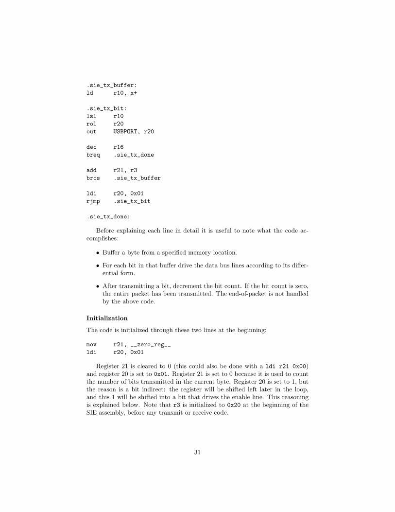
.sie_tx_buffer:ld r10, x+
.sie_tx_bit:lsl r10rol r20out USBPORT, r20
dec r16breq .sie_tx_done
add r21, r3brcs .sie_tx_buffer
ldi r20, 0x01rjmp .sie_tx_bit
.sie_tx_done:
Before explaining each line in detail it is useful to note what the code ac-complishes:
• Buffer a byte from a specified memory location.
• For each bit in that buffer drive the data bus lines according to its differ-ential form.
• After transmitting a bit, decrement the bit count. If the bit count is zero,the entire packet has been transmitted. The end-of-packet is not handledby the above code.
Initialization
The code is initialized through these two lines at the beginning:
mov r21, __zero_reg__ldi r20, 0x01
Register 21 is cleared to 0 (this could also be done with a ldi r21 0x00)and register 20 is set to 0x01. Register 21 is set to 0 because it is used to countthe number of bits transmitted in the current byte. Register 20 is set to 1, butthe reason is a bit indirect: the register will be shifted left later in the loop,and this 1 will be shifted into a bit that drives the enable line. This reasoningis explained below. Note that r3 is initialized to 0x20 at the beginning of theSIE assembly, before any transmit or receive code.
31
Buffering
The next line of code will buffer a byte from memory:
.sie_tx_buffer:ld r10, x+
The code is given a label because it will be branched to later in the loop.The memory location is assumed to be preloaded in the register pair x12. Notethat the value of x is incremented after each load. The next time this loadinstruction is executed, x will already point to the next byte to buffer.
Bit load and transmit
.sie_tx_bit:lsl r10rol r20out USBPORT, r20
At the beginning of this code we have a byte that needs to be transmittedstored in r10. The register r20 has also been set to 0x01 as a result of theinitialization instructions above.
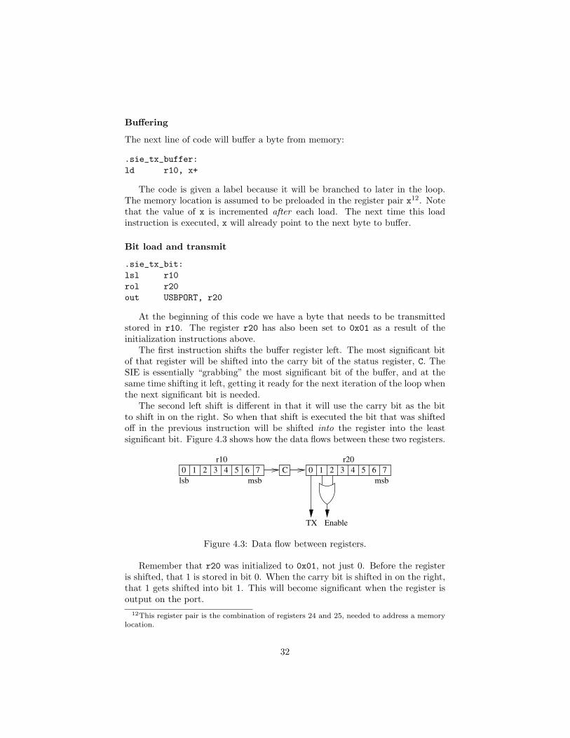
The first instruction shifts the buffer register left. The most significant bitof that register will be shifted into the carry bit of the status register, C. TheSIE is essentially “grabbing” the most significant bit of the buffer, and at thesame time shifting it left, getting it ready for the next iteration of the loop whenthe next significant bit is needed.
The second left shift is different in that it will use the carry bit as the bitto shift in on the right. So when that shift is executed the bit that was shiftedoff in the previous instruction will be shifted into the register into the leastsignificant bit. Figure 4.3 shows how the data flows between these two registers.
0 76543210 7654321 C
r10 r20
msblsb msb
TX Enable
Figure 4.3: Data flow between registers.
Remember that r20 was initialized to 0x01, not just 0. Before the registeris shifted, that 1 is stored in bit 0. When the carry bit is shifted in on the right,that 1 gets shifted into bit 1. This will become significant when the register isoutput on the port.
12This register pair is the combination of registers 24 and 25, needed to address a memorylocation.
32
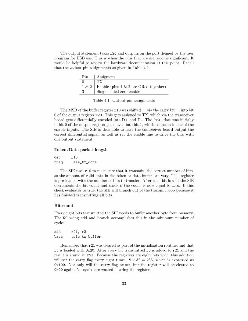
The output statement takes r20 and outputs on the port defined by the userprogram for USB use. This is when the pins that are set become significant. Itwould be helpful to review the hardware documentation at this point. Recallthat the output pin assignments as given in Table 4.1.
Pin Assigment0 TX1 & 2 Enable (pins 1 & 2 are ORed together)3 Single-ended-zero enable
Table 4.1: Output pin assignments
The MSB of the buffer register r10 was shifted — via the carry bit — into bit0 of the output register r20. This gets assigned to TX, which via the transceiverboard gets differentially encoded into D+ and D-. The 0x01 that was initiallyin bit 0 of the output register got moved into bit 1, which connects to one of theenable inputs. The SIE is thus able to have the transceiver board output thecorrect differential signal, as well as set the enable line to drive the bus, withone output statement.
Token/Data packet length
dec r16breq .sie_tx_done
The SIE uses r16 to make sure that it transmits the correct number of bits,as the amount of valid data in the token or data buffer can vary. This registeris pre-loaded with the number of bits to transfer. After each bit is sent the SIEdecrements the bit count and check if the count is now equal to zero. If thischeck evaluates to true, the SIE will branch out of the transmit loop because ithas finished transmitting all bits.
Bit count
Every eight bits transmitted the SIE needs to buffer another byte from memory.The following add and branch accomplishes this in the minimum number ofcycles:
add r21, r3brcs .sie_tx_buffer
Remember that r21 was cleared as part of the initialization routine, and thatr3 is loaded with 0x20. After every bit transmitted r3 is added to r21 and theresult is stored in r21. Because the registers are eight bits wide, this additionwill set the carry flag every eight times: 8 × 32 = 256, which is expressed as0x100. Not only will the carry flag be set, but the register will be cleared to0x00 again. No cycles are wasted clearing the register.
33

When the carry is set — signalling the end of a byte — the transmit loopjumps to sie_tx_buffer, where the SIE loads another byte from the token/databuffer into r10.
Loop back
ldi r20, 0x01rjmp .sie_tx_bit
If the code reaches this point then the SIE is in the middle of a byte that hasbeen buffered. The SIE performs the same initialization that it did at the startof the transmit loop and sets r20 to 0x01. Register r21 isn’t touched becausethat is being used to determine the bit count of the current byte. After theregister is re-initialized the SIE jumps back to the sie_tx_bit label.
Notice that if the SIE needed to buffer another byte, it will not execute thiscode before the first bit of the newly buffered byte is transmitted on the port.This leads to a problem: the reason that r20 is set to 0x01 is so the shift leftmoves the 1 into the enable pin. If the transceiver board had only one pin forthe enable line, the SIE would not be able to guarantee that the enable line isset when the first bit of the next byte is transmitted (it will be the last bit thatwas transmitted, which could be either 1 or 0).
This is why both pins 1 and 2 are ORed together to form the enable line.When the SIE needs to buffer another byte, it can go right on and send the firstbit. The 1 in pin 1 — from the 0x01 originally loaded in r21 — will be shiftedinto pin 2. The SIE can guarantee that pin 2 will be 1. In order to make use ofboth pins 1 and 2 the transceiver board ORs the two pins together to form oneenable line.
34

Chapter 5
Hardware
35

5.1 Introduction
This document will describe the physical layer of the USB engine. This consistsof hardware to perform the following functions:
• Encode the output of the microcontroller into a differential signal.
• Drive/release the data lines under control of the software.
• When needed, drive both lines low.
• Fit on a single port of the Mega32
5.2 Design
These constraints are met with standard 7400 ICs. The design is shown inFigure 5.1.
D+
D−
SE0
TX
En
En
3A
G
A/B
1A
1B
2A
2B
4B
4A
3B
1Y
2Y
3Y
4Y
74157
8GND16 VCC
4
7
15
1
2
3
5
6
11
10
14
13
9
12
Figure 5.1: The final hardware design
The following sections will explain the design.
5.2.1 Encoding the output
A USB connector has two data lines: D+ and D-. Together these are used totransmit a differential signal. The states of the line are shown in Table 5.1.
The Serial Interface Engine on the Mega32 only outputs one line: TX. Thisline needs to be encoded into a differential signal in order to be transmittedon the bus. Encoding the output of the microcontroller is solved by adding aninverter to the output, and using the output of that along with the originalsignal.
36

D+ D- Meaning0 0 Single-ended 00 1 Differential 01 0 Differential 11 1 Illegal state
Table 5.1: States allowed by the USB specification
This solution works for the differential 0 and 1 states, but does not allowus to drive a single-ended 0. In order to this the differential lines are fed intoa 2-input 2:1 multiplexer. D+ and D- are connected to the “A” inputs, andthe “B” inputs are tied to ground. By toggling the select line of the MUX thehardware can select either the differential signal or pull both lines to ground(i.e. the single-ended 0).
At this point the output of the MUX is either a differential 1 or 0, or asingle-ended 0. This is all that is needed to transmit on the bus.
5.2.2 Transmit and receive
To operate correctly the USB host needs to be able to monitor the data lines forcommunication from devices as well as drive the data lines to transmit data. Todo this the hardware sends the output of the MUX (explained above) througha tri-state buffer for each of the data lines.
When the enable of the tri-state buffers is set the host can drive the lineswith the output of the MUX. When the enable line is not set a device will beable to drive the data lines without interference from the host.
The hardware necessary to receive a signal is easier. The data lines can beconnected directly to the port on the Mega32. The SIE requires two copies ofD+ and one D-.
5.2.3 Port configuration
In total the host controller uses seven out of the eight pins on the Mega32. SeeTable 5.2.
Pin Function Notes0 Tx1 Enable ORed with pin 2 to form one enable line.2 Enable See pin 1.3 SE0 Single-ended 0 enable.4 N/A5 D-6 D+ Two copies of this signal are required.7 D+ See pin 6.
Table 5.2: Pin assignments
37

5.2.4 USB timing considerations
The USB 2.0 specification has constraints on the electrical performance of aUSB connection. The host controller hardware has to meet or exceed thesespecifications. A few of the timing constraints that pertain to the hardware arelisted in Table 5.3.
Measurement Expected performanceData line rise/fall time 10ns < t < 20rsDifferential “cross point” 1.3V < V < 2.0V
Table 5.3: Certain timing restrictions
Meeting the rise/fall time
This constraint is given by the hardware for free. Both the inverter and Mega32rise/fall time is about 12ns, as is the delay of the tri-state buffers.
Meeting the cross point
This requirement states that during transitions from a differential 1 to 0 (andvice versa) the voltage at which the differential lines are equal must be between1.3V and 2.0V. This is at the bus (where voltage is from 0V to 3.3V), but thisrequirement is hard to meet earlier in the hardware even when the voltages areat the TTL level.
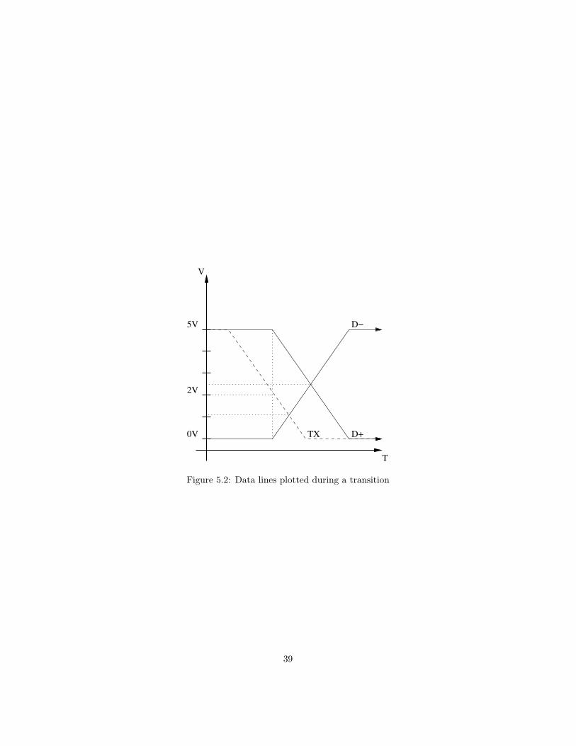
The easiest way to encode the output into a differential signal is to use aninverter to create the D- signal, which is what the simple design discussed abovedid. However, this breaks the cross point requirement. Refer to Figure 5.2 tohelp explain this problem.
The illustrated transition is from a differential 1 to a differential 0. Theproblem is that the inverter will not switch until the input voltage (TX) crossesbelow 2.0 volts. Only when this happens will the inverter pull D- high. By thispoint, however, the TX line is so close to 0V that the D- line “crosses” D+ ata very low voltage (about 1.0V to 1.1V). This is out of spec. In order for thecross point to meet the specifications the cross point needs to be at about 2.5Vat this stage in the hardware.
The same problem occurs at the transition from a differential 0 to a differ-ential 1, albeit at a voltage closer to 5V.
The way the hardware gets around this is to use a buffer on the TX line. D-is still generated by an inverter, but instead of D+ being the original TX linethe TX line is fed into a buffer, the output of which is D+. Because the bufferand inverter have similar input voltage thresholds they switch at the same time.This returns the cross point to spec.
38
T
V
5V
0V
D−
D+
2V
TX
Figure 5.2: Data lines plotted during a transition
39

Appendix A
Acknowledgments
40

We’d like to recognize and thank the following individuals for their contri-butions, who have — directly or indirectly — influenced this project and helpedus bring it to completion:
• Benjamin Hutton, for being on the original team that created the firstrevision; in the process proving that USB on a Mega32 was indeed possible.Several portions of his code have survived through the many revisions.
• Professor Bruce R. Land, for being a tremendous source of wisdom andpractical know-how, as well as providing impetus for the project. Withouthis ECE 476 class this project would have never began.
41


