Table of Contents About This Manual .......................................................................................................... iii
Document Purpose and Intended Audience.............................................................................. iii What’s New in This Document .................................................................................................. iii Document Summary.................................................................................................................. iii Product-Related Documentation ............................................................................................... iii
Upgrades......................................................................................................................... iv
USB Mode ................................................................................................................................. 7 Serial Port Mode........................................................................................................................ 8
Overview ......................................................................................................................... 9 USB4000 Connected to Computer Prior to SpectraSuite Installation.............................. 9
Windows Operating Systems .................................................................................................... 9 Remove the Unknown Device from Windows Device Manager ........................................... 9 Remove Improperly Installed Files........................................................................................ 10
Mac Operating Systems ............................................................................................................ 10 Linux Operating Systems .......................................................................................................... 11
Appendix A: Calibrating the Wavelength of the USB4000...............13
Overview ......................................................................................................................... 13 About Wavelength Calibration......................................................................................... 13 Calibrating the Spectrometer........................................................................................... 14
Preparing for Calibration............................................................................................................ 14 Calibrating the Wavelength of the Spectrometer ...................................................................... 14
Saving the New Calibration Coefficients: USB Mode ...................................................... 16
Quasi-Real Time Acquisition Mode ........................................................................................... 19 Appendix C: Specifications................................................................21
Overview ......................................................................................................................... 21 How the USB4000 Works................................................................................................ 21
About This Manual Document Purpose and Intended Audience This document provides the users of USB4000 Spectrometers with instructions for setting up, calibrating and performing experiments with their spectrometer.
What’s New in This Document This version of the USB4000 Fiber Optic Spectrometer Installation and Operation Manual updates the Ocean Optics list of offices.
Document Summary Chapter Description
Chapter 1: Introduction Contains descriptive information about the USB4000 Spectrometer and how sampling works. It also provides a list of system requirements, interface options, and shipment components.
Chapter 2: Installing the USB4000 Provides installation instructions.
Chapter 3: Troubleshooting Contains recommended steps to isolate and correct common problems.
Appendix A: Calibrating the Wavelength of the USB4000
Provides instructions for calibrating the USB4000 Spectrometer.
Appendix B: External Triggering Contains information about external triggering for the USB4000.
Appendix C: Specifications Contains technical specifications and connector pinouts for the USB4000 Spectrometer.
Product-Related Documentation You can access documentation for Ocean Optics products by visiting our website at http://www.oceanoptics.com. Select Technical → Operating Instructions, then choose the appropriate document from the available drop-down lists. Or, use the Search by Model Number field at the bottom of the web page.
• Detailed instructions for SpectraSuite Spectrometer Operating Software are located at: http://www.oceanoptics.com/technical/SpectraSuite.pdf.
• Detailed instructions for the Breakout Box are located at: http://www.oceanoptics.com/technical/HR4_breakout.pdf.
• Detailed instructions for external triggering are located at: http://www.oceanoptics.com/technical/external triggering.pdf.
Engineering-level documentation is located on our website at Technical → Engineering Docs.
You can also access operating instructions for Ocean Optics products from the Software and Technical Resources CD that ships with the product.
Upgrades Occasionally, you may find that you need Ocean Optics to make a change or an upgrade to your system. To facilitate these changes, you must first contact Customer Support and obtain a Return Merchandise Authorization (RMA) number. Please contact Ocean Optics for specific instructions when returning a product.
Introduction Product Overview The Ocean Optics USB4000 Spectrometer is our next generation, high-performance, miniature fiber-optic spectrometer designed from our popular USB2000 model to include an advanced detector and powerful high-speed electronics. New features consist of the 3648-element detector with shutter, high-speed electronics, and interface capabilities to Linux, Macintosh and Windows operating systems. The USB4000 is responsive from 200-1100 nm, but the specific range and resolution depends on your grating and entrance slit selections.
The USB4000 is perfect for applications where enhanced electronics, high resolution and fast integration times are required.
Data programmed into a memory chip on each USB4000 includes wavelength calibration coefficients, linearity coefficients, and the serial number unique to each spectrometer. Our spectrometer operating software simply reads these values from the spectrometer — a feature that enables hot swapping of spectrometers among computers.
The USB4000 Spectrometer connects to a computer via the USB port or serial port. When connected through a USB 2.0 or 1.1, the spectrometer draws power from the host computer, eliminating the need for an external power supply. The USB4000, like all USB devices, can be controlled by our SpectraSuite software, a completely modular, Java-based spectroscopy software platform that operates on Windows, Macintosh and Linux operating systems.
Ocean Optics USB4000 Fiber Optic Spectrometer
211-00000-000-02-1006 1
1: Introduction
Features TCD1304AP Detector Responsive from 200 to 1100 nm, specific range and resolution depends on your grating and
entrance slit choices Sensitivity of up to 130 photons/count at 400 nm; 60 photons/count at 600 nm An optical resolution of ~0.3 (FWHM) A wide variety of optics available
Integration times from 10 µs to 65 seconds Embedded microcontroller allows programmatic control of all operating parameters and
standalone operation • USB 2.0 480Mbps (high speed) and 12Mbps (full speed) • RS232 115K baud • Multiple communication standards for digital accessories (SPI, I2C)
Low power consumption of only 250 mA @ 5 VDC 16 bit, 3MHz A/D Converter 5 triggering modes 2 programmable strobe signals for triggering other devices 24-pin connector for interfacing to external products Programmable for Standalone Operation CE Certification
System Requirements You can use the USB4000’s USB connectivity with any computer that meets the following requirements:
• Operating system is one of the following: • Windows – 98/Me/2000/XP • Apple Macintosh – OS X version 10.0 or later • Linux – Red Hat 9 or later, Fedora (any version), Debian 3.1 (Sarge), and SUSE (9.0 or
later) • Ocean Optics’ SpectraSuite software application installed and configured for use with the
USB4000.
2 211-00000-000-02-1006
1: Introduction
EEPROM Utilization An EEPROM memory chip in each USB4000 contains wavelength calibration coefficients, linearity coefficients, and a serial number unique to each individual spectrometer. The SpectraSuite software application reads these values directly from the spectrometer, enabling the ability to “hot-swap” spectrometers between computers without entering the spectrometer coefficients manually on each computer.
About SpectraSuite SpectraSuite is the latest generation of operating software for all Ocean Optics spectrometers. It is a completely modular, Java-based spectroscopy software platform that operates on Windows, Macintosh and Linux operating systems. The software can control any Ocean Optics USB spectrometer and device, as well as any other manufacturer’s USB instrumentation using the appropriate drivers.
SpectraSuite is a user-customizable, advanced acquisition and display program that provides a real-time interface to a variety of signal-processing functions. With SpectraSuite, you have the ability to perform spectroscopic measurements (such as absorbance, reflectance, and emission), control all system parameters, collect and display data in real time, and perform reference monitoring and time acquisition experiments. Consult the SpectraSuite manual for hardware requirements when using SpectraSuite (see Product-Related Documentation).
Sampling System Overview How Sampling Works Ocean Optics components function in a sampling system as follows:
1. The user stores reference and dark measurements to correct for instrument response variables.
2. The light from the light source transmits through an optical fiber to the sample.
3. The light interacts with the sample.
4. Another optical fiber collects and transmits the result of the interaction to the spectrometer.
5. The spectrometer measures the amount of light and transforms the data collected by the spectrometer into digital information.
6. The spectrometer passes the sample information to SpectraSuite.
7. SpectraSuite compares the sample to the reference measurement and displays processed spectral information.
Modular Light Sources and Sampling Accessories Ocean Optics offers a complete line of spectroscopic accessories for use with the USB4000. Most of our spectroscopic accessories have SMA connectors for application flexibility. Accordingly, changing the sampling system components is as easy as unscrewing a connector and replacing an accessory. Available accessories include the following:
• USB-ISS-UV-VIS Integrated Sampling System for Cuvettes (200–1100 nm)
211-00000-000-02-1006 3
1: Introduction
• USB-ISS-VIS Integrated Sampling System for Cuvettes (390–900 nm) • USB-LS-450 Pulsed Blue LED Module • USB-DT Deuterium Tungsten Light Source (200–2000 nm) • HR4-BREAKOUT Breakout Box for Controlling Devices (see Breakout Box)
Interface Options The USB4000 has both USB and serial port connectors (with the use of an adapter), enabling you to connect the spectrometer to a computer via a USB or serial port. However, you must create custom software if using the serial port. SpectraSuite software is available if you are connecting via the USB port.
Breakout Box Ocean Optics also offers the Breakout Box (HR4-BREAKOUT), a passive module that separates the signals from their 22-pin port to an array of standard connectors and headers, enabling easy access to a variety of features found in Ocean Optics’ USB4000 Spectrometer. In addition to the accessory connector, the breakout box features a circuit board based on a neutral breadboard pattern that allows custom circuitry to be prototyped on the board itself.
Shipment Components The following information and documentation ships with the USB4000 Spectrometer:
Packing List The packing list is inside a plastic bag attached to the outside of the shipment box (the invoice arrives separately). It lists all items in the order, including customized components in the spectrometer (such as the grating, detector collection lens, and slit). The packing list also includes the shipping and billing addresses, as well as any items on back order.
USB Cable (USB-CBL-1) Use this cable to connect your spectrometer to a computer running on a Windows, Mac or Linux operating system.
Wavelength Calibration Data Sheet Each spectrometer is shipped with a Wavelength Calibration Data Sheet that contains information unique to your spectrometer. SpectraSuite Operating Software reads this calibration data from your spectrometer when it interfaces to a computer via the USB port.
Note
Please save the Wavelength Calibration Data Sheet for future reference.
4 211-00000-000-02-1006
1: Introduction
Software and Technical Resources CD Each order ships with the Ocean Optics Software and Resources CD. This disc contains software, operating instructions, and product information for all Ocean Optics software, spectrometers, and spectroscopic accessories. You need Adobe Acrobat Reader version 6.0 or higher to view these files. Ocean Optics includes the Adobe Acrobat Reader on the Software and Technical Resources CD.
Ocean Optics software requires a password during the installation process. You can locate passwords for the other software applications on the back of the Software and Technical Resources CD package.
Overview You must install the SpectraSuite software application prior to connecting the USB4000 Spectrometer to the computer. The SpectraSuite software installation installs the drivers required for USB4000 installation. If you do not install SpectraSuite first, the system will not properly recognize the USB4000.
If you have already connected the USB4000 to a computer running on a Windows platform prior to installing SpectraSuite, consult Chapter 3: Troubleshooting for information on correcting a corrupt USB4000 installation.
Note the spectrometer(s) that you have installed are listed in the Data Sources pane.
USB4000 Installation This section contains instructions for connecting the USB4000 via both USB and serial modes.
USB Mode Note
The USB port on a computer can power up to five USB4000 spectrometer channels. Systems with more than five channels require a powered USB hub.
► Procedure Follow the steps below to connect the USB4000 to a computer via the USB port:
1. Install SpectraSuite on the destination computer.
2. Locate the USB cable (USB-CBL-1) provided with the USB4000.
3. Insert the square end of the cable into the side of the USB4000.
4. Insert the rectangular end of the cable into the USB port of the computer.
If you installed SpectraSuite prior to connecting the USB4000, the SpectrSuite installs the USB4000 drivers. If the drivers do not successfully install (or if you connected the USB4000 to the computer before installing SpectraSuite), consult Chapter 3: Troubleshooting.
211-00000-000-02-1006 7
2: Installing the USB4000
If you have followed the previous steps and started SpectraSuite, the spectrometer is already acquiring data. Even with no light in the spectrometer, there should be a dynamic trace displayed in the bottom of the graph. If you allow light into the spectrometer, the graph trace should rise with increasing light intensity. This means the software and hardware are correctly installed.
Note the spectrometer(s) that you have installed are listed in the Data Sources pane.
Once you install the software and hardware, and establish your sampling system, you are ready to take measurements.
Serial Port Mode To use the serial port capacity of the USB4000 Spectrometer, the computer must be running a 32-bit version of the Windows operating system.
► Procedure Follow the steps below to connect the USB4000 to the computer via serial port:
1. Connect the serial cable adapter block to the appropriate pins of the USB4000’s 30-Pin Accessory Connector.
2. Connect one end of the 9-pin serial cable to the adapter block on the USB4000, and then connect the other end to a serial port on the computer.
3. Note the number of the serial port (COM Port) to which you connected the USB4000 (some computers may not have numbered ports; handheld computers typically have only one serial port).
4. Plug the 5 VDC external power supply into an outlet and connect it to the USB4000.
Connect Spectroscopic Accessories To find operating instructions for USB4000-compatible products (such as light sources, sampling chambers, and probes), consult the Software and Technical Resources CD or the Ocean Optics website at http://www.oceanoptics.com/technical/operatinginstructions.asp.
External Triggering Options You can trigger the USB4000 using a variety of External Triggering options through the 22-pin Accessory Connector on the spectrometer. See Appendix B: External Triggering for more information.
Troubleshooting Overview The following sections contain information on troubleshooting issues you may encounter when using the USB4000 Spectrometer.
USB4000 Connected to Computer Prior to SpectraSuite Installation Windows Operating Systems If you connected your Ocean Optics USB4000 device to the computer prior to installing your Ocean Optics software application on a Windows platform, you may encounter installation issues that you must correct before your Ocean Optics device will operate properly.
Follow the applicable steps below to remove the incorrectly installed device, device driver, and installation files.
Note
If these procedures do not correct your device driver problem, you must obtain the Correcting Device Driver Issues document from the Ocean Optics website: http://www.oceanoptics.com/technical/engineering/correctingdevicedriverissues.pdf.
Remove the Unknown Device from Windows Device Manager
► Procedure 1. Open Windows Device Manager. Consult the Windows operating instructions for your computer
for directions, if needed.
2. Locate the Other Devices option and expand the Other Devices selection by clicking on the "+" sign to the immediate left.
Improperly installed USB devices can also appear under the Universal Serial Bus Controller option. Be sure to check this location if you cannot locate the unknown device.
3. Locate the unknown device (marked with a large question mark). Right-click on the Unknown Device listing and select the Uninstall or Remove option.
4. Click the OK button to continue. A warning box appears confirming the removal of the Unknown Device. Click the OK button to confirm the device removal.
5. Disconnect the USB4000 from your computer.
6. Locate the section in this chapter that is appropriate to your operating system and perform the steps in the following Remove Improperly Installed Files section.
Remove Improperly Installed Files
► Procedure 1. Open Windows Explorer.
2. Navigate to the Windows | INF directory.
Note
If the INF directory is not visible, you must disable the Hide System Files and Folders and Hide File Extensions for Known File Types options in Windows Folder Options. Access Windows Folder Options from Windows Explorer, under the Tools | Folder Options menu selection.
3. Delete the OOI_USB.INF in the INF directory. If your computer is running either the Windows 2000 or XP operating system, you must also delete the OOI_USB.PNF file in the INF directory.
4. Navigate to the Windows | System32 | Drivers directory.
5. Delete the EZUSB.SYS file.
6. Reinstall your Ocean Optics application and reboot the system when prompted.
7. Plug in the USB device.
The system is now able to locate and install the correct drivers for the USB device.
Mac Operating Systems Since there are no device files for the USB4000 Spectrometer in a Mac operating system, you should not encounter any problems if you installed the spectrometer before the SpectraSuite software.
10 211-00000-000-02-1006
3: Troubleshooting
Linux Operating Systems For Linux operating systems, all you need to do is install the SpectraSuite software, then unplug and replug in the spectrometer. Technically, the driver files for Linux simply give nonprivileged users permission to use newly connected hardware. There isn’t any long-term harm to plugging in the device before installing the software.
211-00000-000-02-1006 11
3: Troubleshooting
12 211-00000-000-02-1006
Appendix A
Calibrating the Wavelength of the USB4000
Overview This appendix describes how to calibrate the wavelength of your spectrometer. Though each spectrometer is calibrated before it leaves Ocean Optics, the wavelength for all spectrometers will drift slightly as a function of time and environmental conditions. Ocean Optics recommends periodically recalibrating the USB4000.
About Wavelength Calibration You are going to be solving the following equation, which shows that the relationship between pixel number and wavelength is a third-order polynomial:
λp = I + C1 p + C2 p2 + C3 p3
Where:
λ = the wavelength of pixel p
I = the wavelength of pixel 0
C1 = the first coefficient (nm/pixel)
C2 = the second coefficient (nm/pixel2)
C3 = the third coefficient (nm/pixel3)
Rλ = the reference intensity at wavelength λ
You will be calculating the value for I and the three Cs.
211-00000-000-02-1006 13
A: Calibrating the Wavelength of the USB4000
Calibrating the Spectrometer Preparing for Calibration To recalibrate the wavelength of your spectrometer, you need the following components:
• A light source capable of producing spectral lines
Note
Ocean Optics’ HG-1 Mercury-Argon lamp is ideal for recalibration. If you do not have an HG-1, you need a light source that produces several (at least 4-6) spectral lines in the wavelength region of your spectrometer.
• An USB4000 spectrometer • An optical fiber (for spectrometers without a built-in slit, a 50-µm fiber works best) • A spreadsheet program (Excel or Quattro Pro, for example) or a calculator that performs third-
order linear regressions
Note
If you are using Microsoft Excel, choose Tools | Add-Ins and check AnalysisToolPak and AnalysisTookPak-VBA.
Calibrating the Wavelength of the Spectrometer ► Procedure Perform the steps below to calibrate the wavelength of the spectrometer:
1. Place SpectraSuite into Scope mode and take a spectrum of your light source. Adjust the integration time (or the A/D conversion frequency) until there are several peaks on the screen that are not off-scale.
2. Move the cursor to one of the peaks and position the cursor so that it is at the point of maximum intensity.
3. Record the pixel number that is displayed in the status bar or legend (located beneath the graph). Repeat this step for all of the peaks in your spectrum.
4. Use the spreadsheet program or calculator to create a table like the one shown in the following figure. In the first column, place the exact or true wavelength of the spectral lines that you used.
In the second column of this worksheet, place the observed pixel number. In the third column, calculate the pixel number squared, and in the fourth column, calculate the pixel number cubed.
5. Use the spreadsheet or calculator to calculate the wavelength calibration coefficients. In the spreadsheet program, find the functions to perform linear regressions.
• If using Quattro Pro, look under Tools | Advanced Math • If using Excel, look under Analysis ToolPak
6. Select the true wavelength as the dependent variable (Y). Select the pixel number, pixel number squared, and the pixel number cubed as the independent variables (X). After executing the regression, you will obtain an output similar to the one shown below. Numbers of importance are noted.
Regression Statistics Multiple R 0.999999831 R Square 0.999999663 R Squared Adjusted R Square 0.999999607 Standard Error 0.125540214 Observations 22
Intercept Coefficients Standard Error Intercept 190.473993 0.369047536 First coefficient X Variable 1 0.36263983 0.001684745 X Variable 2-1.174416E-05 8.35279E-07 X Variable 3-2.523787E-09 2.656608E-10 Second coefficient Third coefficient
211-00000-000-02-1006 15
A: Calibrating the Wavelength of the USB4000
7. Record the Intercept, as well as the First, Second, and Third Coefficients. Additionally, look at the value for R squared. It should be very close to 1. If not, you have most likely assigned one of your wavelengths incorrectly.
Keep these values at hand.
Saving the New Calibration Coefficients: USB Mode Ocean Optics programs wavelength calibration coefficients unique to each USB4000 onto an EEPROM memory chip in the USB4000.
You can overwrite old calibration coefficients on the EEPROM if you are using the USB4000 via the USB port.
► Procedure To save wavelength calibration coefficients using the USB mode, perform the following steps:
1. Ensure that the USB4000 is connected to the computer and that you have closed all other applications.
2. Point your browser to http://www.oceanoptics.com/technical/softwaredownloads.asp and scroll down to Microcode. Select USB EEPROM Programmer.
3. Save the setup file to your computer.
4. Run the Setup.exe file to install the software. The Welcome screen appears.
5. Click the Next button. The Destination Location screen appears.
6. Accept the default installation location, or click the Browse button to specify a directory. Then, click the Next button. The Program Manager Group screen appears.
7. Click the Next button. The Start Installation screen appears.
8. Click the Next button to begin the installation. Once the installation finishes, the Installation Complete screen appears.
9. Click the Finish button and reboot the computer when prompted.
10. Navigate to the USB EEPROM Programmer from the Start menu and run the software.
11. Click on the desired USB4000 device displayed in the left pane of the USB Programmer screen.
12. Double-click on each of the calibration coefficients displayed in the right pane of the USB Programmer screen and enter the new values acquired in Steps 5 and 6 of the Calibrating the Wavelength of the Spectrometer section in this appendix.
13. Repeat Step 12 for all of the new values.
14. Click on the Save All Values button to save the information, and then Exit the USB Programmer software.
The new wavelength calibration coefficients are now loaded onto the EEPROM memory chip on the USB4000.
External Triggering Overview The USB4000 supports five triggering modes, which are set with the Trigger Mode command. A detail of each triggering mode follows.
Normal (Free Running) In this mode, the USB4000 uses the user-defined integration clock and continuously scans the CCD array. All of the signals described in the previous section are provided by the spectrometer to the CCD automatically based on the integration time selected in the software by the user.
External Software Trigger In this mode, the ExtTrigIn signal acts as an enable switch. If ExtTrigIn is kept HIGH, the USB4000 will acquire spectra as if it was in the normal free running mode. If ExtTrigIn is kept LOW, the USB4000 will not acquire spectra.
External Hardware Trigger In this mode, the USB4000 uses the software (user) defined integration clock; however, the integration period doesn’t begin until the External Trigger Input Signal (ExtTrigIn) goes HIGH. If no External Trigger Input Signal is applied, the spectrometer will not take any spectra, and the software will appear “frozen” until an External Trigger Input Signal is detected. With ExtTrigIn going HIGH, the spectrometer will provide the required signals to the CCD as shown below (note that in the following diagram, the spectrometer is in non-shutter mode):
211-00000-000-02-1006 17
B: External Triggering
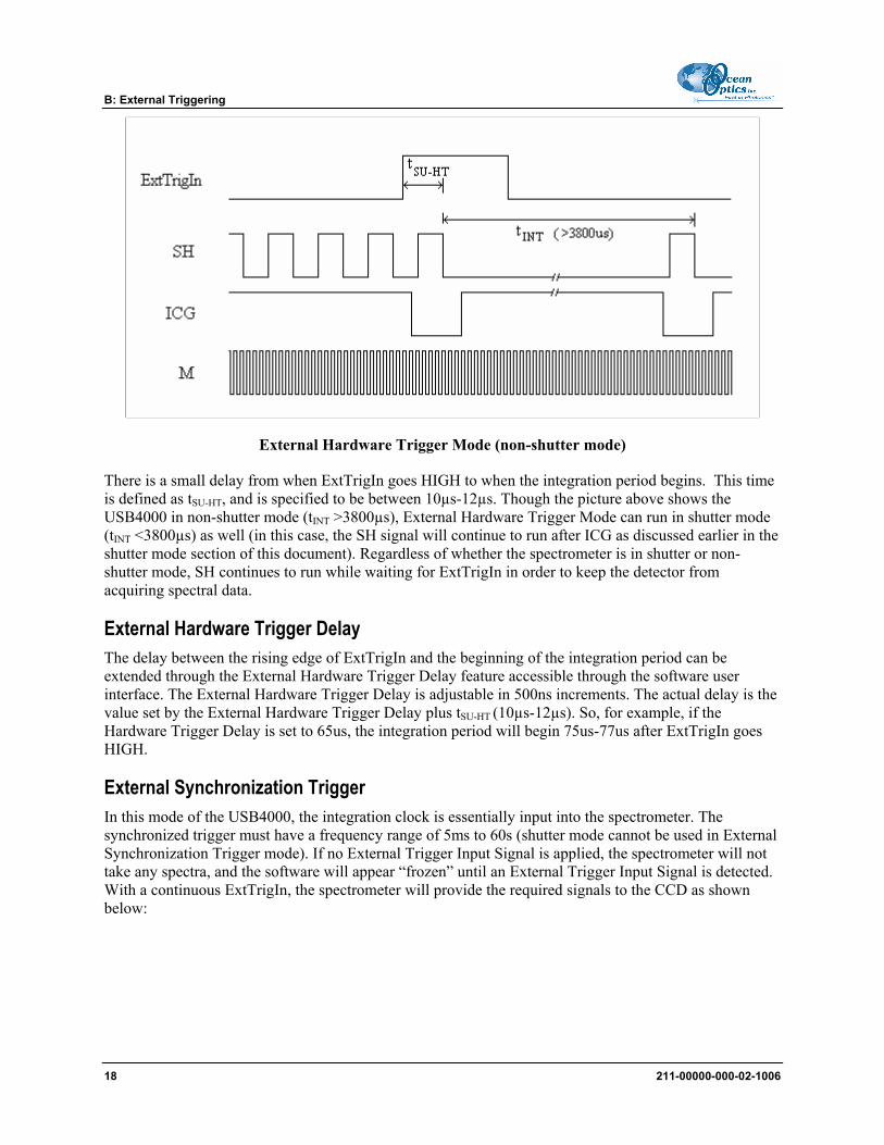
External Hardware Trigger Mode (non-shutter mode)
There is a small delay from when ExtTrigIn goes HIGH to when the integration period begins. This time is defined as tSU-HT, and is specified to be between 10µs-12µs. Though the picture above shows the USB4000 in non-shutter mode (tINT >3800µs), External Hardware Trigger Mode can run in shutter mode (tINT <3800µs) as well (in this case, the SH signal will continue to run after ICG as discussed earlier in the shutter mode section of this document). Regardless of whether the spectrometer is in shutter or non-shutter mode, SH continues to run while waiting for ExtTrigIn in order to keep the detector from acquiring spectral data.
External Hardware Trigger Delay The delay between the rising edge of ExtTrigIn and the beginning of the integration period can be extended through the External Hardware Trigger Delay feature accessible through the software user interface. The External Hardware Trigger Delay is adjustable in 500ns increments. The actual delay is the value set by the External Hardware Trigger Delay plus tSU-HT (10µs-12µs). So, for example, if the Hardware Trigger Delay is set to 65us, the integration period will begin 75us-77us after ExtTrigIn goes HIGH.
External Synchronization Trigger In this mode of the USB4000, the integration clock is essentially input into the spectrometer. The synchronized trigger must have a frequency range of 5ms to 60s (shutter mode cannot be used in External Synchronization Trigger mode). If no External Trigger Input Signal is applied, the spectrometer will not take any spectra, and the software will appear “frozen” until an External Trigger Input Signal is detected. With a continuous ExtTrigIn, the spectrometer will provide the required signals to the CCD as shown below:
18 211-00000-000-02-1006
B: External Triggering
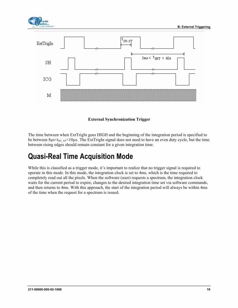
External Synchronization Trigger
The time between when ExtTrigIn goes HIGH and the beginning of the integration period is specified to be between 8µs<tSU_ST<10µs. The ExtTrigIn signal does not need to have an even duty cycle, but the time between rising edges should remain constant for a given integration time.
Quasi-Real Time Acquisition Mode While this is classified as a trigger mode, it’s important to realize that no trigger signal is required to operate in this mode. In this mode, the integration clock is set to 4ms, which is the time required to completely read out all the pixels. When the software (user) requests a spectrum, the integration clock waits for the current period to expire, changes to the desired integration time set via software commands, and then returns to 4ms. With this approach, the start of the integration period will always be within 4ms of the time when the request for a spectrum is issued.
211-00000-000-02-1006 19
B: External Triggering
20 211-00000-000-02-1006
Appendix C
Specifications Overview This appendix contains information on spectrometer operation, specifications, and system compatibility. It also includes accessory connector pinout diagrams and pin-specific information.
How the USB4000 Works Below is a diagram of how light moves through the optical bench of an USB4000 Spectrometer. The optical bench has no moving parts that can wear or break; all the components are fixed in place at the time of manufacture. Items with an asterisk (*) are user-specified.
USB4000 Spectrometer with Components
See USB4000 Components Table on the following page for an explanation of the function of each numbered component in the USB4000 Spectrometer in this diagram.
211-00000-000-02-1006 21
C: Specifications
USB4000 Components Table Ocean Optics permanently secures all components in the USB4000 at the time of manufacture. Only Ocean Optics technicians can replace interchangeable components, where noted.
Item Name Description
1 SMA 905 Connector
Secures the input fiber to the spectrometer. Light from the input fiber enters the optical bench through this connector.
2 Slit
A dark piece of material containing a rectangular aperture, which is mounted directly behind the SMA Connector. The size of the aperture (from 5 µm to 200 µm) regulates the amount of light that enters the optical bench and controls spectral resolution.
You can also use the USB4000 without a Slit. In this configuration, the diameter of the fiber connected to the USB4000 determines the size of the entrance aperture.
Only Ocean Optics technicians can change the Slit.
3 Filter
Restricts optical radiation to pre-determined wavelength regions. Light passes through the Filter before entering the optical bench. Both bandpass and longpass filters are available to restrict radiation to certain wavelength regions.
Only Ocean Optics technicians can change the Filter.
4 Collimating Mirror
Focuses light entering the optical bench towards the Grating of the spectrometer. Specify standard or SAG+.
Light enters the spectrometer, passes through the SMA Connector, Slit, and Filter, and then reflects off the Collimating Mirror onto the Grating.
5 Grating
Diffracts light from the Collimating Mirror and directs the diffracted light onto the Focusing Mirror. Gratings are available in different groove densities, allowing you to specify wavelength coverage and resolution in the spectrometer.
Only Ocean Optics technicians can change the Grating.
6 Focusing Mirror
Receives light reflected from the Grating and focuses first-order spectra onto the detector plane.
7 L4 Detector Collection Lens
An optional component that attaches to the Detector to increase light-collection efficiency. It focuses light from a tall slit onto the shorter Detector elements.
The L4 Detector Collection Lens should be used with large diameter slits or in applications with low light levels. It also improves efficiency by reducing the effects of stray light.
Only Ocean Optics technicians can add or remove the L4 Detection Collection Lens.
8 Detector (UV or VIS)
Collects the light received from the Focusing Mirror or L4 Detector Collection Lens and converts the optical signal to a digital signal. Each pixel on the Detector responds to the wavelength of light that strikes it, creating a digital response. The spectrometer then transmits the digital signal to the SpectraSuite application.
22 211-00000-000-02-1006
C: Specifications
Item Name Description
9 OFLV Filters
OFLV Variable Longpass Order-sorting Filters block second- and third-order light. These filters are optional.
10 UV4 Detector Upgrade
The detector’s standard window is replaced with a quartz window to enhance spectrometer performance (<340 nm). This upgrade is optional.
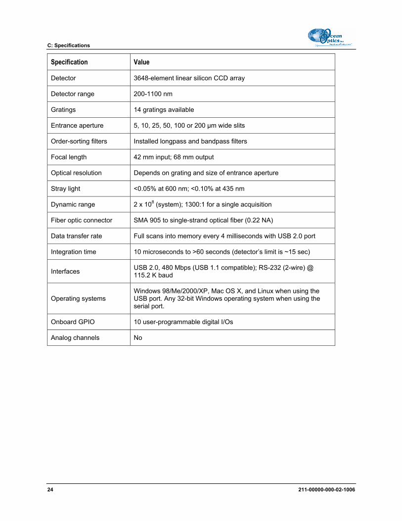
USB4000 Specifications The following sections provide specification information for the CCD detector in the USB4000, as well as the USB4000 Spectrometer itself.
CCD Detector Specifications Specification Value
Detector Toshiba TCD1304AP linear CCD array
No. of elements 3648 pixels
Sensitivity 130 photons per count at 400 nm; 60 photons/count at 600 nm
Order-sorting filters Installed longpass and bandpass filters
Focal length 42 mm input; 68 mm output
Optical resolution Depends on grating and size of entrance aperture
Stray light <0.05% at 600 nm; <0.10% at 435 nm
Dynamic range 2 x 10⁸ (system); 1300:1 for a single acquisition
Fiber optic connector SMA 905 to single-strand optical fiber (0.22 NA)
Data transfer rate Full scans into memory every 4 milliseconds with USB 2.0 port
Integration time 10 microseconds to >60 seconds (detector’s limit is ~15 sec)
Interfaces USB 2.0, 480 Mbps (USB 1.1 compatible); RS-232 (2-wire) @ 115.2 K baud
Operating systems Windows 98/Me/2000/XP, Mac OS X, and Linux when using the USB port. Any 32-bit Windows operating system when using the serial port.
Onboard GPIO 10 user-programmable digital I/Os
Analog channels No
24 211-00000-000-02-1006
C: Specifications
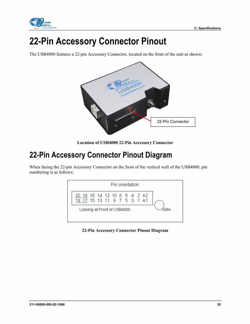
22-Pin Accessory Connector Pinout The USB4000 features a 22-pin Accessory Connector, located on the front of the unit as shown:
22-Pin Connector
Location of USB4000 22-Pin Accessory Connector
22-Pin Accessory Connector Pinout Diagram When facing the 22-pin Accessory Connector on the front of the vertical wall of the USB4000, pin numbering is as follows:
22-Pin Accessory Connector Pinout Diagram
211-00000-000-02-1006 25
C: Specifications
22-Pin Accessory Connector – Pin Definitions and Descriptions The following table contains information regarding the function of each pin in the USB4000’s 22-Pin Accessory Connector:
Pin # Function Input/Output Description
1 VCC, VUSB, or 5VIN
Input or Output
Input power pin for USB4000 – When operating via USB, this pin can power other peripherals – Ensure that peripherals comply with USB specifications
2 RS232 Tx Output RS232 transmit signal – Communicates with a computer over DB9 Pin 2
3 RS232 Rx Input RS232 receive signal – Communicates with a computer over DB9 Pin 3
4 Lamp Enable Output TTL signal driven Active HIGH when the Lamp Enable command
is sent to the spectrometer
5 Continuous Strobe Output TTL output signal used to pulse a strobe – Divided down from the
master clock signal
6 Ground Input/Output Ground
7 External Trigger In Input TTL input trigger signal – See External Triggering Options
document for info
8 Single Strobe Output
TTL output pulse used as a strobe signal – Has a programmable delay relative to the beginning of the spectrometer integration period
9 I2C SCL Input/Output The I2C clock signal for communications to other I2C peripherals.
10 I2C SDA Input/Output The I2C Data signal for communications to other I2C peripherals.
11 MOSI Output SPI Master Out Slave In (MOSI) signal for communication to other SPI peripherals
12 MISO Input SPI Master In Slave Out (MISO) signal for communication to other SPI peripherals
13 GPIO-1(1P)* Input/Output General purpose software-programmable, digital input/output
(channel number)
14 GPIO-0(2P)* Input/Output General purpose software-programmable, digital input/output
(channel number)
26 211-00000-000-02-1006
C: Specifications
Pin # Function Input/Output Description
15 GPIO-3(1N)* Input/Output General purpose software-programmable, digital input/output
(channel number)
16 GPIO-2(2N)* Input/Output General purpose software-programmable, digital input/output
(channel number)
17 GPIO-5(3P)* Input/Output General purpose software-programmable, digital input/output
(channel number)
18 GPIO-4(4P)* Input/Output General purpose software-programmable, digital input/output
(channel number)
19 GPIO-7(3N)* Input/Output General purpose software-programmable, digital input/output
(channel number)
20 GPIO-6(4N)* Input/Output General purpose software-programmable, digital input/output
(channel number)
A1 SPI_CLK Output SPI clock signal for communication to other SPI peripherals
A2 SPICS OUT Output The SPI Chip/Device Select signal for communications to other SPI peripherals
* NOTE: GPIO nP and nN are for future LVDS capability
22-Pin Accessory Connector - Part Numbers The part numbers for the 22-pin accessory connector on the USB4000 Spectrometer are as follows:
• The connector is a Samtec Part Number IPT1-111-01-S-D-RA. • The vertical mating connector is Part Number IPS1-111-01-S-D-VS. • The right-angle PCB mount is Part Number IPS1-111-01-S-D-RA.
If you are customizing your USB4000 Spectrometer system or configuring External Triggering, you may need these part numbers to complete your setup.