13
Use of Advance Scope for Measurement of TP2/ TP4 and Calibration of TP4 Stressor Ali Ghiasi 100GCU Meeting March 13 Kona
Use of Advance Scope for Measurement of TP2/TP4 and Calibration of TP4 Stressor
Ali Ghiasi 100GCU Meeting March 13 Kona
2 100 GCU A. Ghiasi
Overview
• To show feasibility of OIF VSR test specifications these measurement were presented during OIF Q4 2011 meeting – Specific measurements here were made on Agilent DSO-90000 real
time scope but similar measurements can also be made on sampling scope
• The advantage of time domain statistical method is capability to measure TP2 and TP4 compliance on an operating system instead of limited post processing of the channel S-parameters for compliance – The same method can also be used for calibration of the CR4 host
stress signal
• Time domain statistical simulator based on the same principle currently is in use by all SI engineer involved in high speed deigns – The best proof is just looking at contribution given in this group, nearly
all show feasibility with statistical time domain eyes!
3 100 GCU A. Ghiasi
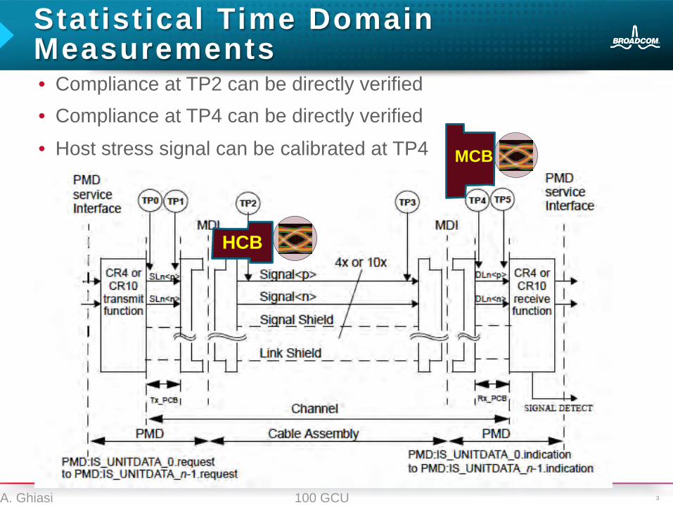
Statistical Time Domain Measurements • Compliance at TP2 can be directly verified • Compliance at TP4 can be directly verified
• Host stress signal can be calibrated at TP4
HCB
MCB

4 100 GCU A. Ghiasi
Constructing VSR Channel and Host
• Based on availability zQSFP MCB was used instead of Quattro based channel
• The channel was build of – Microstrip cal trace with loss of 6.5 dB + zQSFP MCB-HCB with
loss of 5 dB at 14 GHz – Total loss including additional cables was estimated to be 12.25 dB
at 14 GHz
• The transmitter output was set to ~640 mV differential p-p • Transmit FFE post was set to about 2 dB and the CTLE was
doing most of the work – If the FFE was doing most of the work the output eye opening was
about 30% lower
• To excite worst case crosstalk TX1 and TX3 were excited in the zQSFP connector
5 100 GCU A. Ghiasi
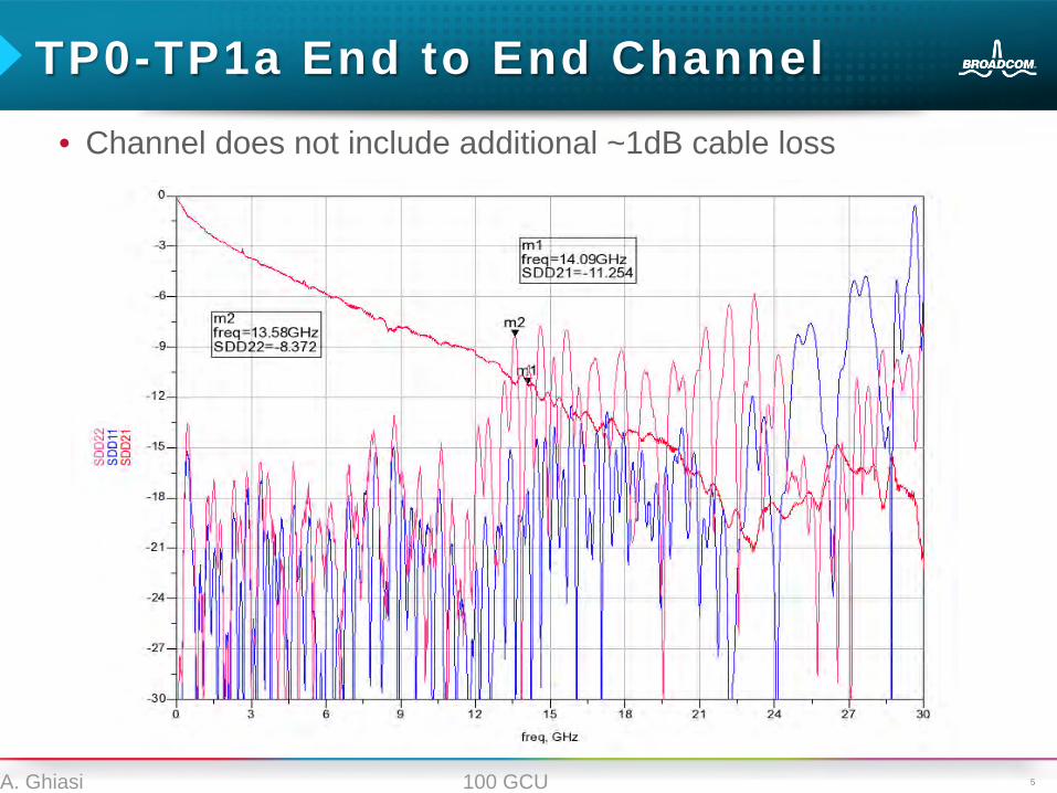
TP0-TP1a End to End Channel • Channel does not include additional ~1dB cable loss
6 100 GCU A. Ghiasi
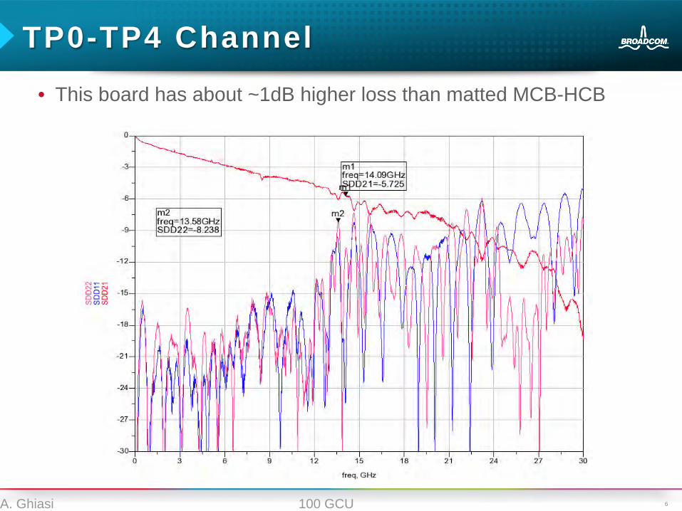
TP0-TP4 Channel
• This board has about ~1dB higher loss than matted MCB-HCB
7 100 GCU A. Ghiasi
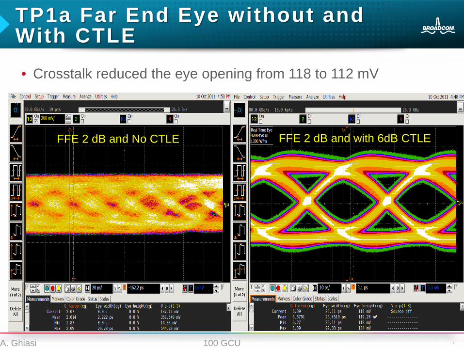
TP1a Far End Eye without and With CTLE
FFE 2 dB and No CTLE FFE 2 dB and with 6dB CTLE
• Crosstalk reduced the eye opening from 118 to 112 mV
8 100 GCU A. Ghiasi
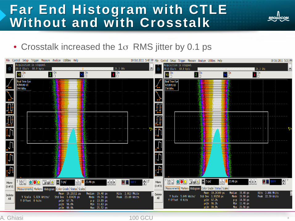
Far End Histogram with CTLE Without and with Crosstalk • Crosstalk increased the 1σ RMS jitter by 0.1 ps

9 100 GCU A. Ghiasi
TP4 Eyes
TP4 FFE 0 dB and 3 dB CTLE
• With 640 mv P-P transmitter in the module and no pre-emphasis – TP4 eye without CTLE 220 mV with 3 dB CTLE 270 mV – Next will show that this eye passes TP5 with 7 dB CTLE
260 mV
10 100 GCU A. Ghiasi
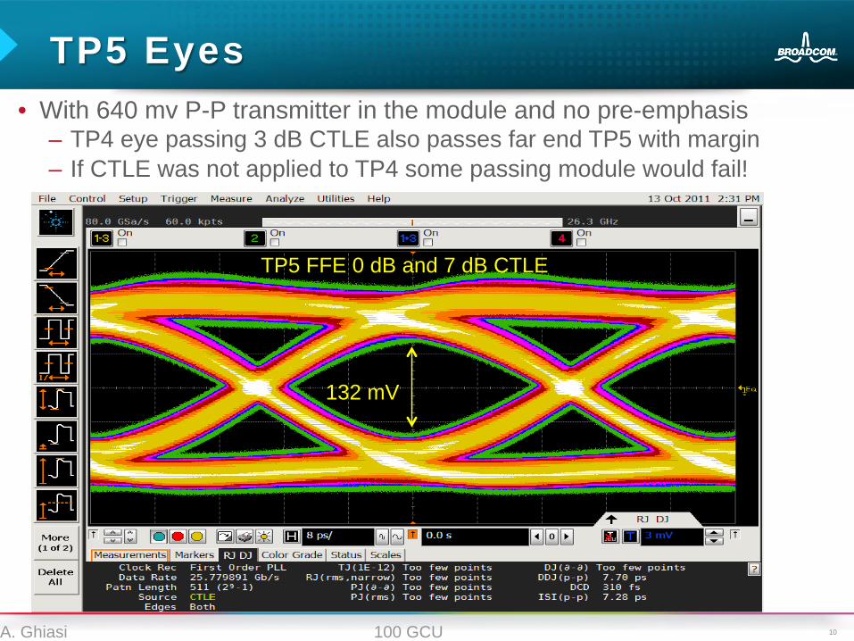
TP5 Eyes
TP5 FFE 0 dB and 7 dB CTLE
• With 640 mv P-P transmitter in the module and no pre-emphasis – TP4 eye passing 3 dB CTLE also passes far end TP5 with margin – If CTLE was not applied to TP4 some passing module would fail!
132 mV
11 100 GCU A. Ghiasi
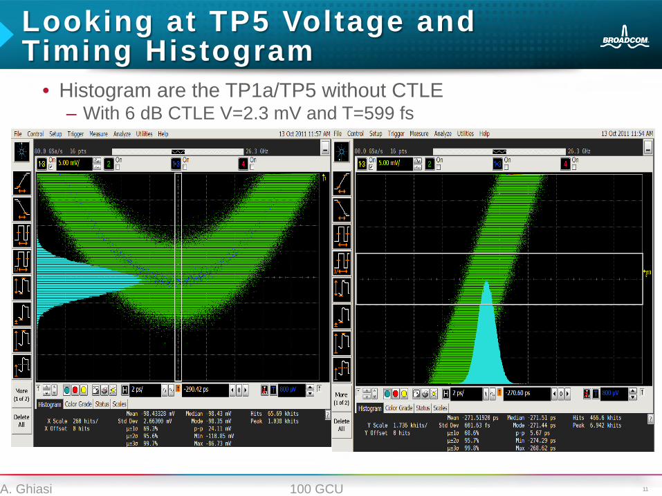
Looking at TP5 Voltage and Timing Histogram
• Histogram are the TP1a/TP5 without CTLE – With 6 dB CTLE V=2.3 mV and T=599 fs
12 100 GCU A. Ghiasi
Summary • These results showed that reference receiver model when
combined with statistical time domain measurement provide the most accurate compliance methodology
• Even with one of fastest scope DSO 90000 with 80 GS/s BER 1E-12 or 1E-15 can not be observed directly – OIF VSR directly measures 10M samples or equivalent number of
edges in case of sampling scope – Then the equivalent eye opening is extrapolate to BER 1E-15 – These scopes are very fast with measurement taking 10’s sec – Scopes do have build in software and/or hardware CDRs
• In OIF VSR a family of CTLE’s were define with specific poles and zeros – Actual receiver implementation might be different but still the
minimum requirement can be traced back to the reference receiver – 100 GCU group would have to agree to an specific reference
receiver to allow taking advantage of the most accurate simulation and measurement capability.
Thank You


![TP2 - Orchestration de Services avec Camunda · TP2 - Orchestration de Services avec Camunda Télécharger PDF [../tp2.pdf ] Objectifs du TP Création d'un processus métier (Business](https://static.documents.pub/doc/80x56/5e0d8596fcade5406c420547/tp2-orchestration-de-services-avec-camunda-tp2-orchestration-de-services-avec.jpg)


