TECHNICAL REPORT STANDARD TITLE PAGE 1. Report No. 2. Accession No. 3. Recipient's Catalog No. FHWA/TX-87/405-2F 4. Title and Subtitle--------L----------·-----1f-: S :-. '""R:-ep-o-rt-=D-ot-e-------- oo Auqust 1987 USE OF GUARDRAILS ON LOW FILL BRIDGE LENGTH CULVERTS 6. Performing Orgoni lotion Code 7, Author's) T. J. Hirsch and Dale Beggs 9. Performing Orgoni zotion Nome and' Address Texas Transportation Institute The Texas A&M University System College Station, Texas 77843 8. Performing Orgoni zotion Report No. Research Report 405-2F 10. Work Unit No. 11. Contract or Grant NOh Study No. 2-5-05-405 1-:-:------------- _____________ -1 13 . Type of Report and Period Covered 12. Sponsoring Agency Nome and Address F. na 1 _ September 1984 Texas State Department of Highways and Public 1 August 1987 I Transportation: Transportation Planning Division P. O. Box 5051 14. Sponsoring Agency Code AIlc;t.in Tpxac; 78763 15. Supplementary Notes Research performed in cooperation with DOT, FHWA. Research Study Title: Guardrail on Low Fill Bridge Length Culverts 16. Abstract When multiple box culverts span over 20 ft, they are defined by AASHTO as bridge length and thus normally require the use of a full strength rigid bridge rail. The use of a rigid bridge rail creates a transition problem between the flexible metal beam guard fence which is commonly used upstream of the bridge rail. It would be safer and more economical to continue the flexible metal beam guard fence across the culvert even when the culvert length is over 20 ft and even when the soil fill depth over the culvert is less than the standard guardrail post embedment depth of 38 in. in Texas. It was believed that more post could be used with a shallow embedment to achieve the desired guardrail strength. A metal beam guard fence design of this type was crash tested in this study and proved to be unsatisfactory. Another concept investigated was to rigidly mount steel guard fence post (with blockout) to the top of the culvert deck when full soil embedment could not be achieved. A design of this type was also crash tested in this study and proved to be satisfactory. 17. Key Words Culverts, Bridge Rails, Guardrails, Longitudinal Barriers, Roadside Barriers. 18. Distribution Statement No restrictions. This document ;s available to the public through the National Technical Information Service 5285 Port Royal Road Springfield, Virginia 22161 19. Security Classif. (of this report) 20. Security Clauif. (of thi. pagel 21. No. of Page. 22. Price Unclassified Unclassified 59 Form DOT F 1700.7 18-69)
FHWA/TX-87/405-2F 4. Title and Subtitle--------L----------·-----1f-:S:-. '""R:-ep-o-rt-=D-ot-e--------
oo
Auqust 1987 USE OF GUARDRAILS ON LOW FILL BRIDGE LENGTH CULVERTS 6. Performing Orgoni lotion Code
7, Author's)
T. J. Hirsch and Dale Beggs 9. Performing Orgoni zotion Nome and' Address Texas Transportation Institute The Texas A&M University System College Station, Texas 77843
8. Performing Orgoni zotion Report No.
Research Report 405-2F 10. Work Unit No.
11. Contract or Grant NOh Study No. 2-5-05-405
1-:-:-------------_____________ -1 13. Type of Report and Period Covered
12. Sponsoring Agency Nome and Address F . na 1 _ September 1984 Texas State Department of Highways and Public 1 August 1987
I Transportation: Transportation Planning Division P. O. Box 5051 14. Sponsoring Agency Code
AIlc;t.in Tpxac; 78763 15. Supplementary Notes
Research performed in cooperation with DOT, FHWA. Research Study Title: Guardrail on Low Fill Bridge Length Culverts
When multiple box culverts span over 20 ft, they are defined by AASHTO as bridge length and thus normally require the use of a full strength rigid bridge rail. The use of a rigid bridge rail creates a transition problem between the flexible metal beam guard fence which is commonly used upstream of the bridge rail. It would be safer and more economical to continue the flexible metal beam guard fence across the culvert even when the culvert length is over 20 ft and even when the soil fill depth over the culvert is less than the standard guardrail post embedment depth of 38 in. in Texas.
It was believed that more post could be used with a shallow embedment to achieve the desired guardrail strength. A metal beam guard fence design of this type was crash tested in this study and proved to be unsatisfactory.
Another concept investigated was to rigidly mount steel guard fence post (with blockout) to the top of the culvert deck when full soil embedment could not be achieved. A design of this type was also crash tested in this study and proved to be satisfactory.
No restrictions. This document ;s available to the public through the National Technical Information Service 5285 Port Royal Road Springfield, Virginia 22161
19. Security Classif. (of this report) 20. Security Clauif. (of thi. pagel 21. No. of Page. 22. Price
Unclassified Unclassified 59
Form DOT F 1700.7 18-69)
USE OF GUARDRAILS ON LOW FILL BRIDGE LENGTH CULVERTS
by
T. J. Hirsch Research Engineer
and
Dale Beggs Research Assistant
Research Report 405-2 (F) on
Research Study No. 2-5-85-405 Guardrail on Low Fill Bridge Length Culverts
Sponsored by
Texas State Department of Highways and Public Transportation in cooperation with
the U.S. Department of Transportation Federal Highway Administration
AU9yst 1987 .- .. ' '.
Texas Transportation Institute The Texas A&M University System College Station, Texas 77843
METRIC CONVERSION FACTORS
= I"! Approximate Conversions to Motrie Meesures
t&I 5!..- Approximate Conversions from Metric Measures s: N -- E ~
Sv .... 1 When You Know Multiplv by To Find Svmbol iii!
Svmbol When You Know Multlplvbv To Find Svmbol
- iii-. ... N
LENGTH 10 I LENGTH - 0 --- N - II
in inches "2.5 nntimete" em 1Ii-. • mm mllllmet .... 0.04 'nchn in ... ft 'Ht 30 centlmet", - == em centimet_ 0.4 Inch .. in em yeI verds 0.9 meter, m -;;r---- S- ID m met", 3.3 fHt ft - ... mi mil .. 1.6 kilomet_ km - m met". 1.1 Vlrd, Vd
mil sqUII' mil .. 2.6 squar. kilomlt_ km' - ... km' square kilom.ter, 0.4 squar. mil., mi' = 0.4 hect., .. he - =-= he heetlr .. (10.000 mil 2.5 Icr .. s::: I"! Icr ..
G! - == ... MASS (weight) - - MASS (weighd - N
- --01 ou_ 21 grlms g - = ... • ",.m. 0.035 oune .. 01 - =- ... Ib pound, 0.45 kilogrlm, kg ,. kg kilogllms 2.2 pound, Ib
short tons 0.9 tonna - E 0 tonn .. llooo kgl 1.1 short ton, - ... 12000 Ibl £: • - VOLUME - =-
VOLUME s:
- E- ID W - == ml millilit." 0.03 fluid ounc .. fI 01
tsp t .. spoons 5 milliliters ml -- !! I liter, 2.1 pints pt - ,.. Tb.p tablespoon, 15 milliliter. ml I Ii .. " 1.06 qUlrtl qt
flol fluid oune .. 30 milliliter, mI - = t&I I liter, 0.26 ,.IIon. gil -c cups 0.24 liter, I - == m' cubic metfl" 35 cubic fftt ft'
0.47 lite" I = m' cubic m ... rs 1.3 cubic yards yd' pt pintl N = III =-cat qUirt. 0.95 lit'" I = =-.. I pllons 3.8 liter, I - == • TEMPERATURE (exact'
ft' CUblCfH' 0.03 cubic miters m' ==-·Vd' m' -
cubic yard, 0.76 cubic mete" - ai- l"! °c Celsius 9/5 II hen Flhrenheit OF == - temperlture Idd 321 temperature
TEMPERATURE (exacd - 55 N
I ~ ~
eF Flhrenhelt 5/911"" C.I,ius °e -- EO-
,ubtr.cting tlmperltur. = u OF tlmplflturt OF
321 32 98.6 712 .40 0 'I~I ~'I·l~, I
160 12~~ I I I I I I I I". I I I I , I , • i , i i , i
"1 in. 2.54lexletlvl. For other e •• et conversion •• nd more detliled tlbles. _ NBS -40 -20 0 20 40 60 80 100
Misc. Publ. 286. Units of Weighlland Me •• ur ... Price $2.25. SO Catllog No. C13.10:286. DC 37 °c
DISCLAIMER
The contents of this report reflect the views of the authors, who are responsible for the opinions, findings and conclusions presented herein. The contents do not necessarily reflect the official views or policies of the Federal Highway Administration. This report does not constitute a standard, specification, or regulation.
This research study was conducted under a cooperative program between the Texas Transportation Institute (TTI), the Texas State Department of Highways and Public Transportation (SDHPT), and the Federal Highway Administration (FHWA). Mr. John J. Panak (Bridge Design Engineer, SDHPT) and Mr. Harold Cooner (Engineer of Geometric Design, SDHPT) were closely involved in all phases of this study
IMPLEMENTATION STATEMENT
As of the writing of this report, the metal beam guard fence mounted on concrete culverts has been utilized in experimental installations on Texas highways.
iii
TABLE OF CONTENTS
TITLE PAGE ABSTRACT DISCLAIMER KEY WORDS ACKNOWLEOGMENTS IMPLEMENTATION STATEMENT TABLE OF CONTENTS LIST OF FIGURES LIST OF TABLES INTRODUCTION METAL BEAM GUARD FENCE DESIGNS AND CRASH TESTS
MODIFIED GUARD FENCE NO.1 Crash Test 1
MODIFIED GUARD FENCE NO.2 Crash Test 2
MODIFIED GUARD FENCE NO.3 Crash Test 3
SUMMARY AND CONCLUSIONS REFERENCE LIST APPENDIX A. GLOSSARY APPENDIX B. METAL BEAM GUARD FENCE - GF(TD) - 84 APPENDIX C. SEQUENCE PHOTOGRAPHS, TESTS 1, 2 and 3 APPENDIX D. ACCELEROMETER DATA, ROLL, PITCH & YAW RATES APPENDIX E. STATIC LOAD TEST DATA FOR GUARD FENCE POST
ATTACHED TO CONCRETE DECK
iv
i
i i
iii
iii
iii
iii
iv v
vi 1
3
3
8
8
12 12 17
23 24
25
26 27
34
47
------------ ---------
LIST OF FIGURES
Fi gure No. Page 1 STANDARD TEXAS TIMBER GUARDRAIL POST AND MODIFIED 2
VERSION USED IN TESTS 1 AND 2 (Prior to 1984) 2 TYPICAL LOAD VS. DEFLECTION DATA FOR 7 IN. DIAMETER 4
TIMBER POST EMBEDDED IN COHENSIONLESS SOIL. 3
4
5
6
7
8
9
10
11
12
13
14
15
16
TABLE 1
SUMMARY OF MAXIMUM FORCE AND ENERGY ABSORBED BY GUARDRAIL POST VS. EMBEDMENT DEPTH PLAN VIEW OF TYPICAL CRASH TEST SITE FOR TESTS 1, 2 AND 3 PLAN VIEW OF MODIFIED GUARD FENCE NO.1 INSTALLATION FOR CRASH TEST 1 MODIFIED GUARD FENCE NO.1 AND CAR BEFORE AND AFTER CRASH TEST 1 SUMMARY OF CRASH TEST 1 PLAN VIEW OF MODIFIED GUARD FENCE NO. 2 INSTALLATION FOR CRASH TEST 2
MODIFIED GUARD FENCE NO. 2 AN~ CAR BEFORE AND AFTER CRASH TEST 2
SUMMARY OF CRASH TEST 2 PLAN VIEW OF MODIFIED GUARD FENCE NO.3 INSTALLATION FOR CRASH TEST 3 DETAIL OF W6 X 9 STEEL GUARDRAIL POST AND ATTACHMENT TO CULVERT SLAB STATIC LOAD TEST RESULTS FOR GUARD FENCE POST USED IN CRASH TEST 3 ANALYSIS OF GUARD FENCE POST LOAD CAPACITY FOR VARIOUS SOIL FILL DEPTHS MODIFIED GUARD FENCE NO. 3 AND CAR BEFORE AND AFTER CRASH TEST 3 SUMMARY OF CRASH TEST 3
LIST OF TABLES
SUMMARY OF BARRIER VII COMPUTER PROGRAM ANALYSIS OF MODIFIED METAL BEAM GUARD FENCE DESIGNS
v
5
6
7
10
11
13
14
15
16
18
19
20
21
22
9
I NTRODUCTI ON
When multiple box culverts span over 20 ft, they are defined by AASHTO
(1)* as bridge length and thus normally require the use of a full strength
rigid bridge rail (see the Glossary in Appendix A for definitions of barrier
types). The use of a rigid bridge rail creates a transition problem between
the flexible metal beam guard fence (see Appendix B for Texas standards)
whi ch is common ly used upstream of the bri dge rail. It woul d be safer and
more economical to continue the flexible metal beam guard fence across the
cul vert even when the cul vert length is over 20 ft and even when the soil
fill depth over the culvert is less than the standard guardrail post
embedment depth of 38 in. Many of these culverts have soil fills of between
6 in. and 38 in.
The objective of this research study was to develop information to
promote the concept of continuing the approach flexible metal beam guard
fence across bridge length (over 20 ft) multiple box culverts. This concept
is believed to be safer, more economical and more effective than using rigid
bridge rails on such culverts.
Research Report 405-1 entitled liThe Effects of Embedment Depth, Soil
Properties, and Post Type on the Performance of Highway Guardrail Post" (5)
presented data which could be used to modify the current metal beam guard
fence for application when the full 38 in. post embedment depth could not be
achieved. It was believed that more post could be used with a shallow
embedment to achieve the desi red guardrail strength. A metal beam guard
fence desi gn of this type was crash tested in this study and proved to be
unsat i sfactory.
Another concept investigated was to rigidly mount the guard fence post
to the top of the cul vert deck when full soil embedment coul d not be
achieved. A design of this type was also crash tested in this study and
proved to be satisfactory.
*Numbers in parentheses, thus (1), refer to corresponding reference in list of references.
1
4"
27"
co M
II
III ttl J:: X -l-l Q) 0.. I- Q)
CI
-l-l C Q)
-e Q) .0 E
L..LJ
21"
-l-l III 0 a.. ~ Q) .0 E
.r-I-
en \.0
~ 0
en -LO
7" diam.
4"
27"
18" Test 1
2,..
27" Test 2
7" diam.
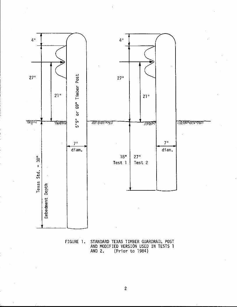
FIGURE 1. STANDARD TEXAS TIMBER GUARDRAIL POST AND MODIFIED VERSION USED IN TESTS 1 AND 2. (Prior to 1984)
2
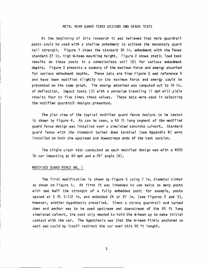
METAL BEAM GUARD FENCE DESIGNS AND CRASH TESTS
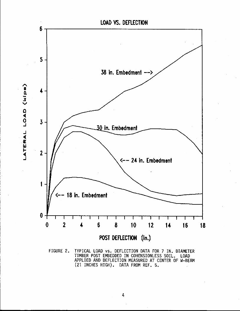
At the beginning of this research it was believed that more guardrail posts coul d be used with a sha 11 ow embedment to achieve the necessary guard rail strength. Figure 1 shows the standard 38 in. embedment with the Texas standard 27 in. high W-beam mounting height. Figure 2 shows static load test results on these posts in a cohesionless soil (6) for various embedment depths. Figure 3 presents a summary of the maximum force and energy absorbed for various embedment depths. These data are from Figure 2 and reference 5 and have been modified slightly so the maximum force and energy could be presented on the same graph. The energy absorbed was computed out to 18 in. of deflection. Impact tests (3) with a pendulum traveling 17 mph will yield results four to five times these values. These data were used in selecting the modified guardrail designs presented.
The plan view of the typical modified guard fence designs to be tested is shown by Figure 4. As can be seen, a 50 ft long segment of the modified
!
guard fence design was installed over a simulated concrete culvert. Standard guard fence with the standard turned down terminal (see Appendix B) were installed on both the upstream and downstream ends of the test section.
The single crash test conducted on each modified design was with a 4500 lb car impacting at 60 mph and a 25° angle (6).
MODIFIED GUARD FENCE NO.1
The first modification is shown by Figure 5 using 7 in. diameter timber as shown on Fi gure 1. At fi rst it was intended to use twi ce as many posts with one half the strength of a fully embedded post: for example, posts spaced at 3 ft 1-1/2 in. and embedded 24 or 27 in. (see Figures 2 and 3). However, another hypothesis prevailed. Since a strong guardrail and turned down end anchor was to be used upstream and downstream of the 50 ft long simulated culvert, the post only needed to hold the W-beam up to make initial contact with the car. The hypothesis was that the W-beam firmly anchored on each end could by itself redirect the car over this 50 ft length.
3
'" II Q. -:I.
v
0 ~ 0 .J
.J ~
.Il bI .. ~ .J
LOAD VS. DEFLECTION 6~----------------------------------------~
5
4
3
. 2
1
o
38 in. Embedment --)
<-- 24 in. Embedment
<-- 18 in. Embedment
2 4 6 8 10 12 14 16
POST DEflECTION (in.)
FIGURE 2. TYPICAL LOAD VS. DEFLECTION DATA FOR 7 IN. DIAMETER TIMBER POST EMBEDDED IN COHENSIONLESS SOIL. LOAD APPLIED AND DEFLECTION MEASURED AT CENTER OF W-BEAM (21 INCHES HIGH). DATA FROM REF. 5.
FIGURE 5. PLAN VIEW OF r·10DIFIED GUARD FENCE NO. INSTALLATION FOR CRASH TEST 1.
20
Impact Posts
._------..
61 '" -,)
, . t ..
0 0
\0 .
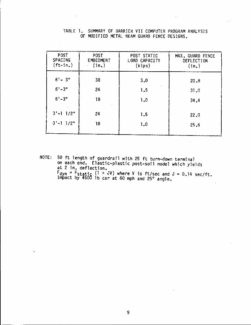
This hypothesis was investigated using the BARRIER VII computer program, and a summary of the results is presented in Table 1. This table indicates the standard guard fence (6 ft-3 in. post spacing with 38 in. embedment) would deflect 20.8 in. when impacted with a 4500 lb car at 60 mph and 250
angle. The modified guard fence No. 1 shown on Figure 5 (6 ft-3 in. post spacing with 18 in. embedment) would deflect 34.4 in.
One problem with the analysis, which crash test 1 will demonstrate, is that RARRIER VII is a planar two-dimensional analysis. BARRIER VII cannot indicate that the W-beam will drop vertically and the car will vault vertically over the guardrail.
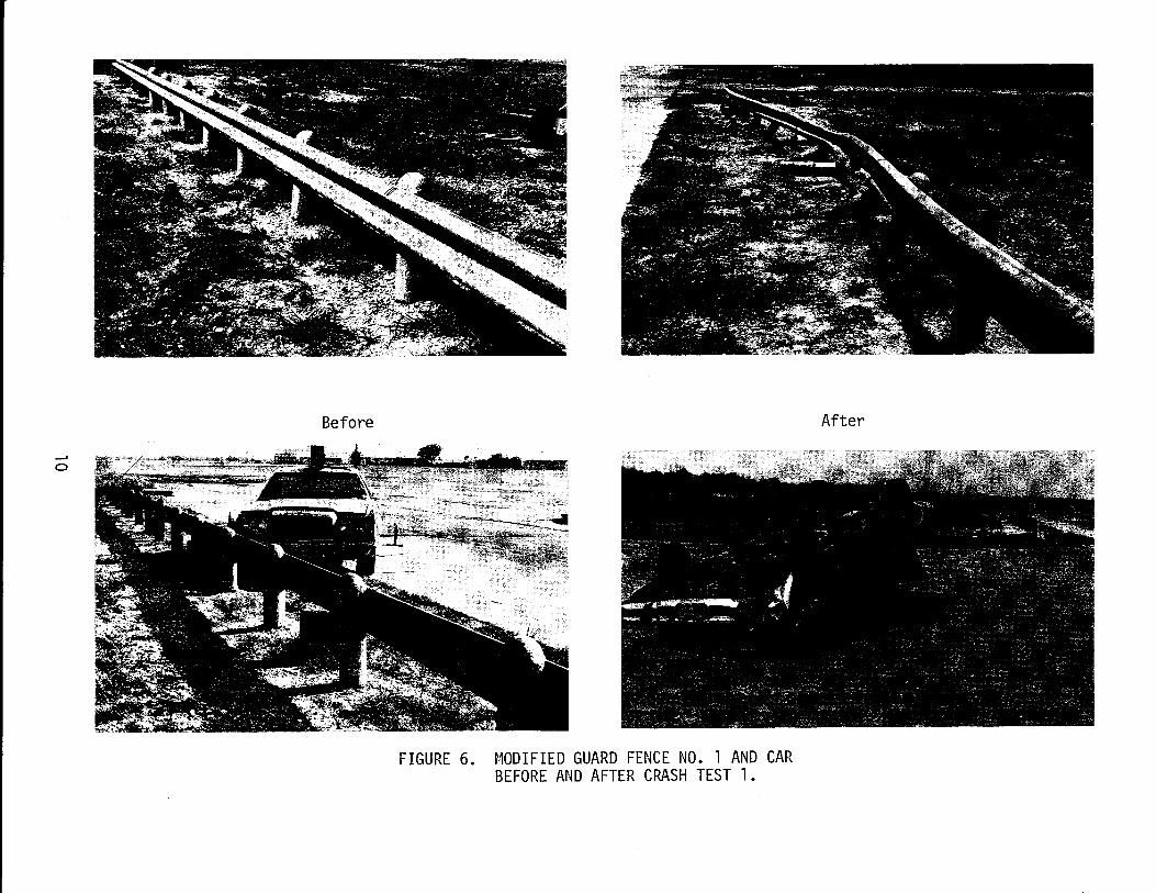
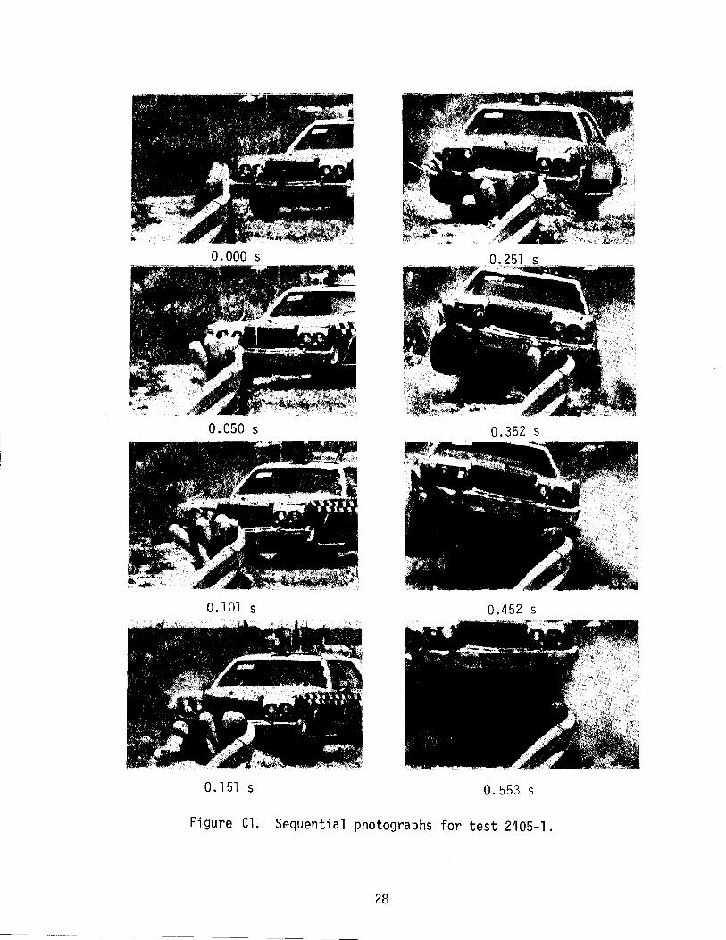
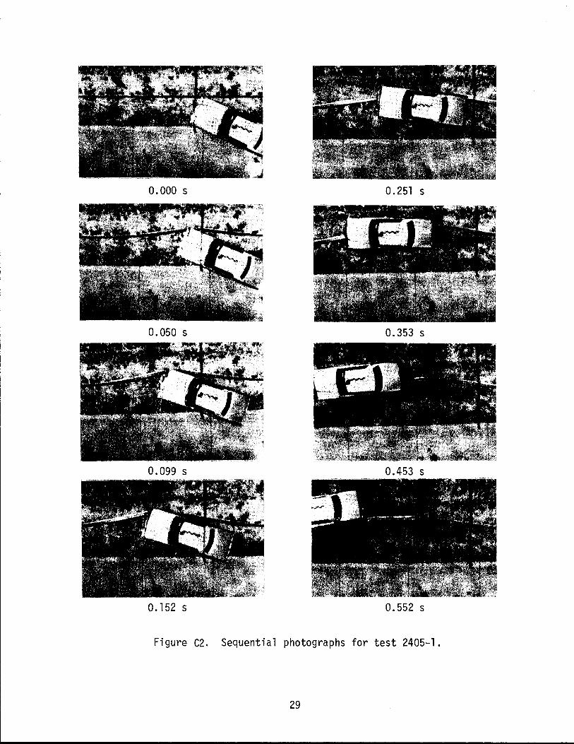
Crash Test 1. Figure 6 shows the modified guard fence installation and car before and after crash test 1. In this test a 4400 1b Chrysler Newport impacted the modified guard fence No.1 at 61.9 mph and 26.20 angle. At 0.2 sec into the impact the car began to parallel the deflected (about 46.8 in.) W-beam rai 1, and the W-beam dropped and the car ramped over it. The car
penetrated behind the rail and rolled over. The test was unsuccessful.
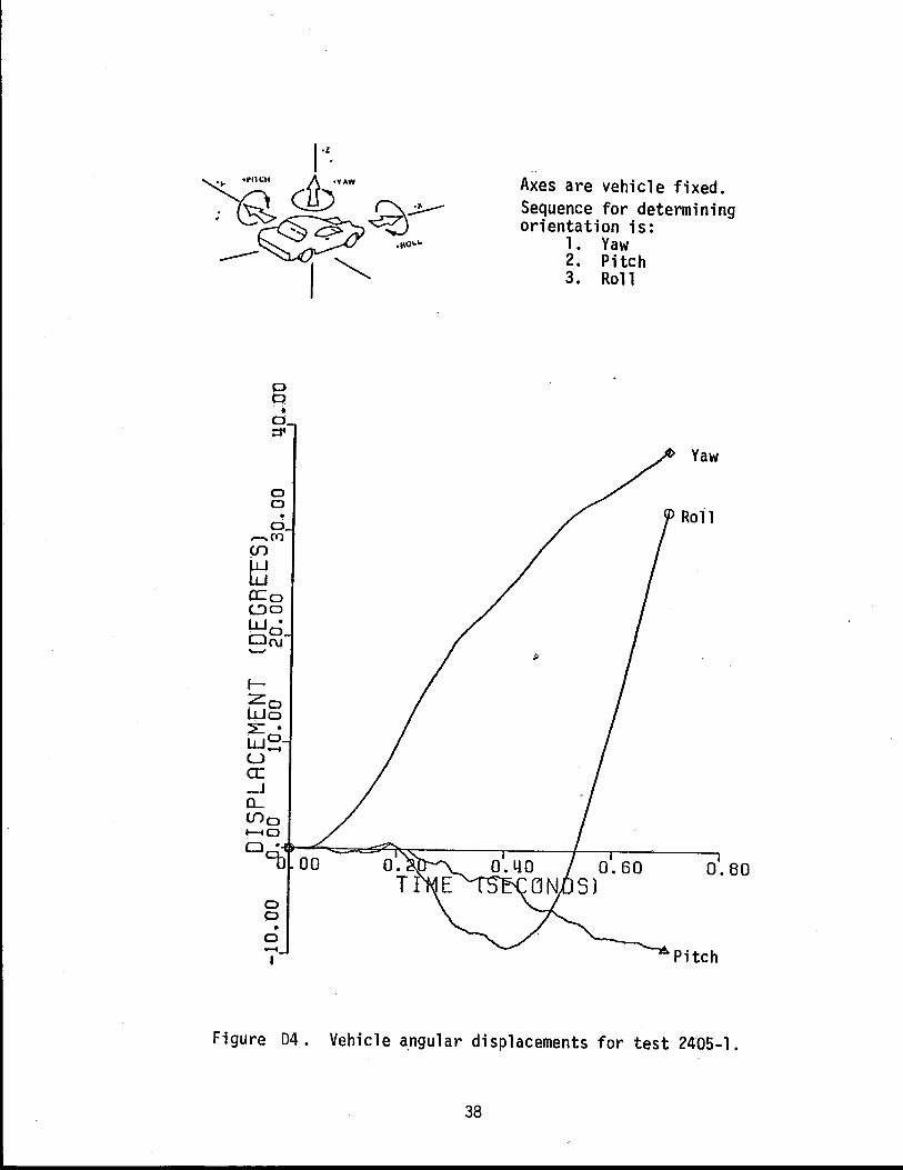
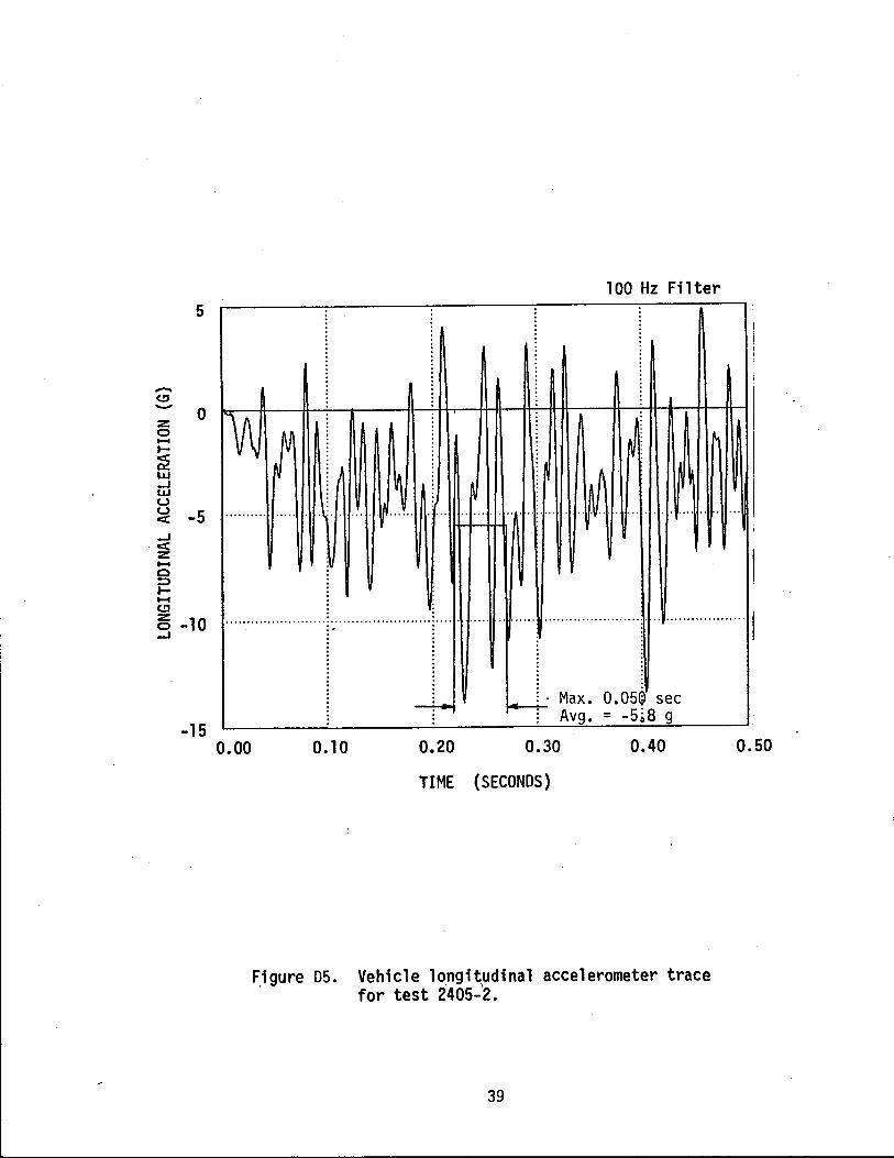
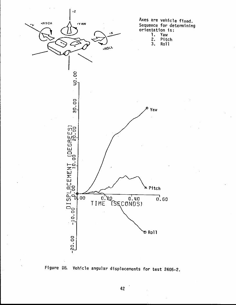
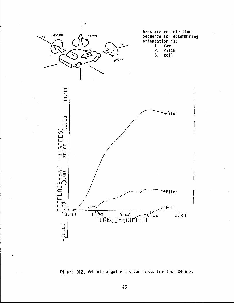
Fi gure 7 presents a summary of the crash test 1 data. Appendi x C presents the seq uence photographs of the test, and Appendi x D presents the accelerometer, roll, pitch, and yaw data from the test vehicle.
MODIFIED GUARD FENCE NO.2
This guard fence design was in accordance with the original hypothesis that one could use twice as many posts with one half the strength to achieve the desired strength for vehicle redirection. Figure 3 was used to select the 7 in. diameter timber post embedded 27 in. in cohensionless soil to obtain one half the strength (both force and energy absorbed) of the standard 38 in. embedded post. This yields the design shown by Figure 8. Interpolating the data in Table 1 would indicate this guard fence design would deflect laterally about 20 in., which is about the same as the standard guard fence.
8
TABLE 1. SUMMARY OF BARRIER VII COMPUTER PROGRAM ANALYSIS OF MODIFIED METAL BEAM GUARD FENCE DESIGNS.
POST POST POST STATIC MAX. GUARD FENCE SPACING EMBEDMENT LOAD CAPACITY DEFLECTION (ft-in.) (in.) (kips) (i n. )
6 1- 311 38 3.0 20.R
6 1 -3 11 24 1.5 31.0
6 1 -3 11 18 1.0 34.4
31 -1 1/211 24 1.5 22.0
31 -1 1/211 18 1.0 25.6
NOTE: 50 ft length of guardrail with 25 ft turn-down terminal on each end. Elastic-plastic post-soil model which yields at 2 in. deflection. Fdyn = Fstatic (1 + JV) where V is ft/sec and J = 0.14 sec/ft. Impact by 4500 lb car at 60 mph and 25° angle.
9
Before
FIGURE 6. MODIFIED GUARD FENCE NO. 1 AND CAR BEFORE AND AFTER CRASH TEST 1.
After
00000 sec
/, .
L
00 251 sec
--- -fIf::J -- __ --ITT-=t _ _ ~~
Test No. Date Face Rai I Post Post Spacing Length of Installation Beam Rail Deflection
"ax. Dynamic "ax. Permanent
Vehicle Damage TAE SA[
• • • • ~. • LLi.--T:-::!"---.----.-
2405-1 7/22/65 12 gao steel W-shape standard timber 1. 9 m (6 ft 3 in) 53.3 m (175 ft)
("ax. 0.050 sec. avg.) Longitudinal Transverse Vertical
FIGURE 7. SUl4MARY OF CRASH TEST 1.
0.452 sec
1971 Chrysler Newport 1996 kg (4400 Ib)
99.4 km/h (61.6 mph) 26.2 degrees
-3.1 g 2.1 g 3.5 g
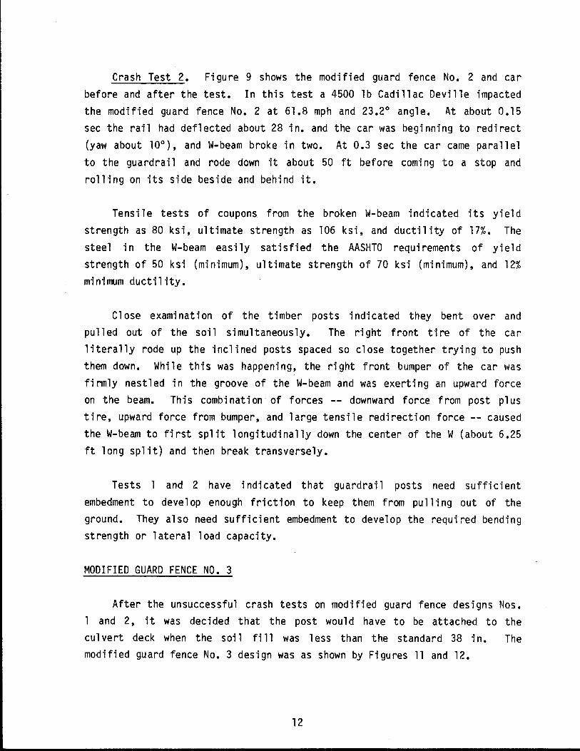
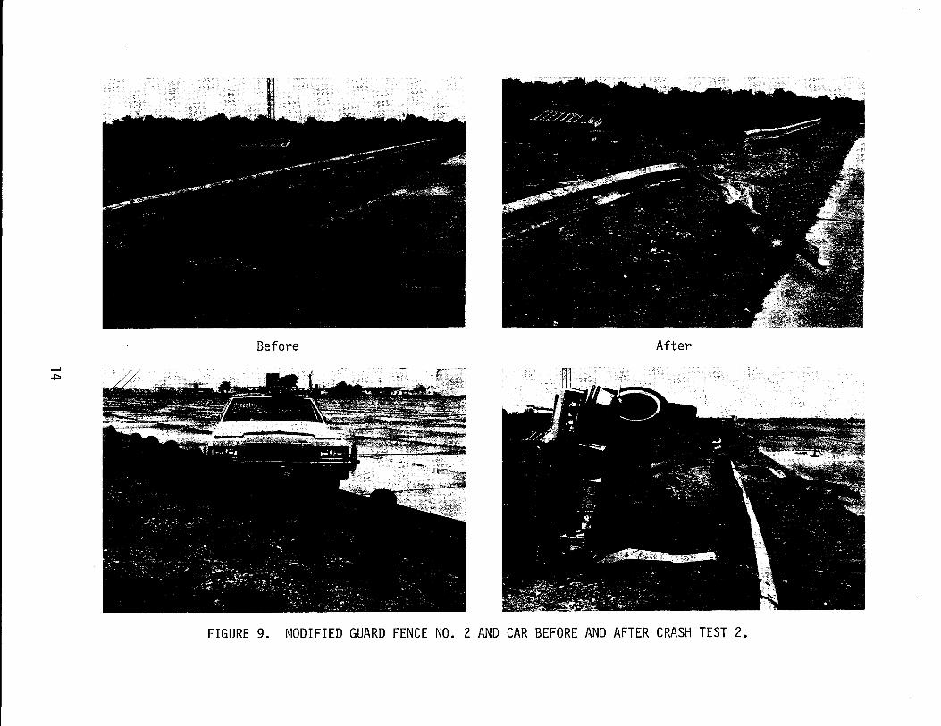
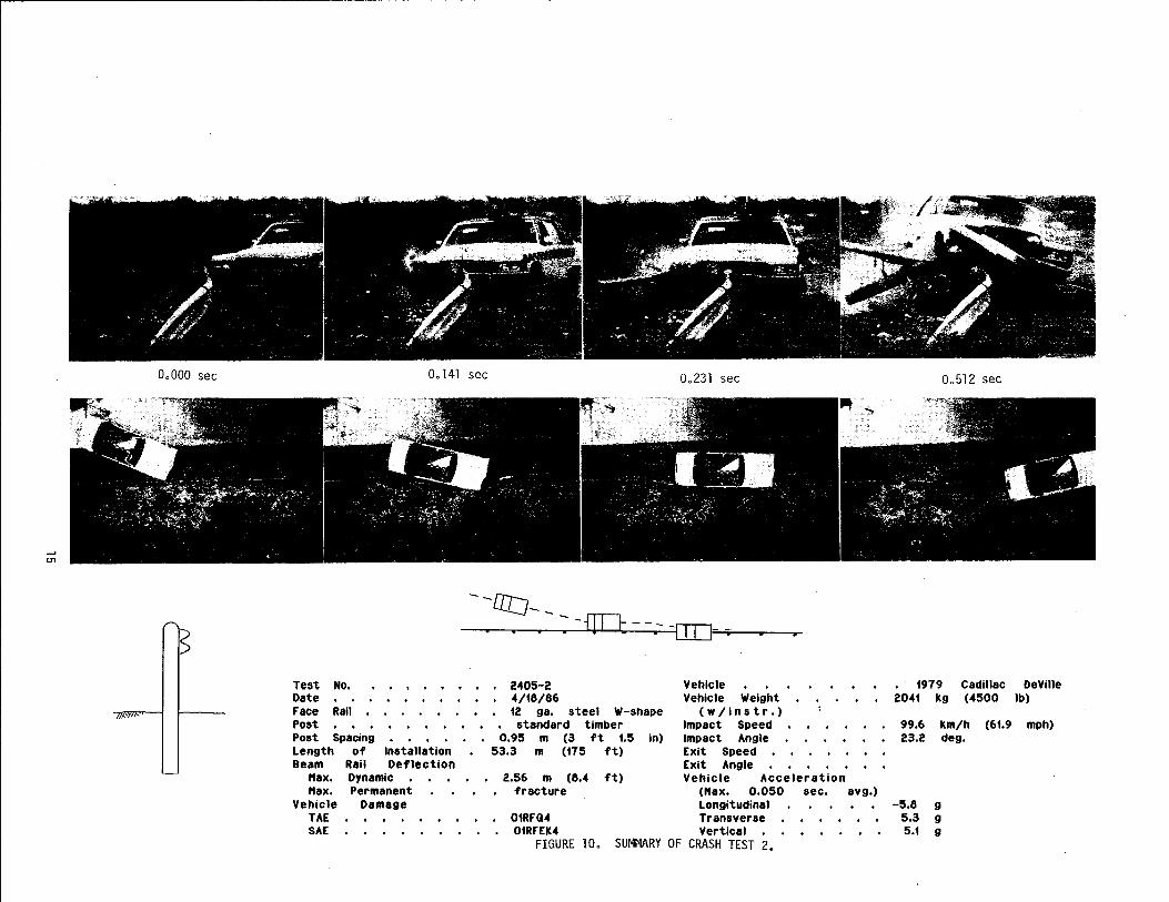
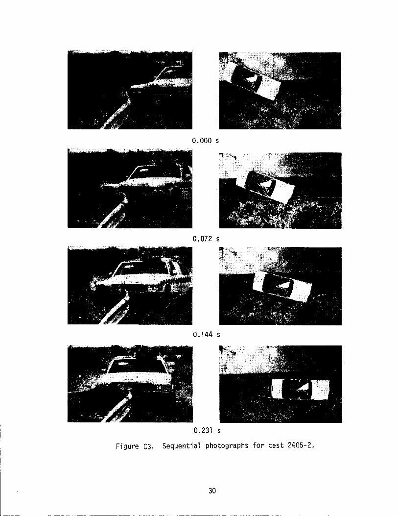
Crash Test 2. Figure 9 shows the modified guard fence No. 2 and car before and after the test. In this test a 4500 1b Cadillac Deville impacted the modified guard fence No.2 at 61.8 mph and 23.2° angle. At about 0.15 sec the rail had deflected about 28 in. and the car was beginning to redirect (yaw about 10°), and W-beam broke in two. At 0.3 sec the car came parallel to the guardrai 1 and rode down it about 50 ft before comi ng to a stop and rolling on its side beside and behind it.
Tensile tests of coupons from the broken W-beam indicated its yield strength as 80 ksi, ultimate strength as 106 ksi, and ductility of 17%. The steel in the W-beam easily satisfied the AASHTO requirements of yield strength of 50 ksi (minimum), ultimate strength of 70 ksi (minimum), and 12% minimum ductility.
Close exami nat i on of the timber posts i ndi cated they bent over and pulled out of the soil simultaneously. The right front tire of the car literally rode up the inclined posts spaced so close together trying to push them down. Whi 1 e thi s was happeni ng, the ri ght front bumper of the car was fi rm1y nestled in the groove of the W-beam and was exerting an upward force on the beam. This combination of forces -- downward force from post plus tire, upward force from bumper, and large tensile redirection force -- caused the W-beam to first split longitudinally down the center of the W (about 6.25 ft long split) and then break transversely.
Tests 1 and 2 have i ndi cated that guardrai 1 posts need suffi ci ent embedment to develop enough friction to keep them from pull i ng out of the ground. They also need sufficient embedment to develop the required bending strength or lateral load capacity.
MODIFIED GUARD FENCE NO.3
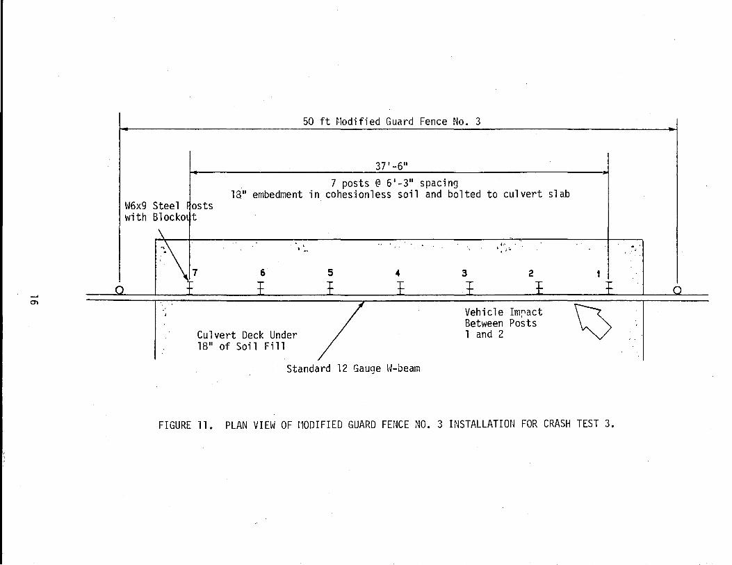
After the unsuccessful crash tests on modified guard fence designs Nos. and 2, it was decided that the post would have to be attached to the
culvert deck when the soil fill was less than the standard 38 in. The modified guard fence No.3 design was as shown by Figures 11 and 12.
FIGURE 8. PLAN V I El·J OF j'1ODIFIED GUARD FE~JCE (W. 2 INSTALL/\TION FOR CRASH TEST 2.
~, . ~.~ , .
" . "
,,:- . ... , " " .
Before After
FIGURE 9. MODIFIED GUARD FENCE NO. 2 AND CAR BEFORE AND AFTER CRASH TEST 2.
00000 sec 00 141 sec 00 231 sec
- -Dl:J--. . . : - f[Tl: - -.- -O::O~---r-
Test No. 2405-2 Vehicle Date .. /18/86 Vehicle Weight Face Rail 12 gao steel W-shape (w/instr.) Post standard timber Impact Speed Post Spacing 0.95 m (3 ft 1.5 in) Impact Angle Length of Installation 53.3 m (175 ft) Exit Speed Beam Rail Deflection Exit Angle
"ax. Dynamic 2.56 m (8." ft) Vehicle Acceleration "ax. Permanent fracture ("ax. 0.050 sec.
18" embedment in cohesion1ess soil and bolted to culvert slab W6x9 Steel osts with Blocko t
7 6
Culvert Deck Under 18" of Soil Fi 11
5
Standard 12 Gauge W-beam
k . . . . . ,. 3 2
Vehicle Im~act Bet\'Ieen Posts 1 and 2
1
FIGURE 11. PLAN VIEW OF r10DIFIED GUARD FENCE NO.3 INSTALLATION FOR CRASH TEST 3.
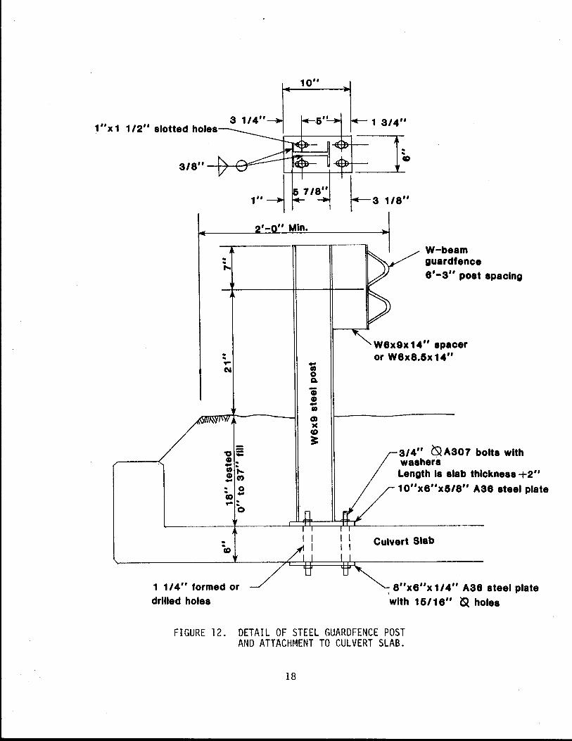
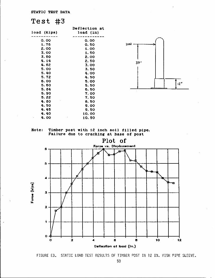
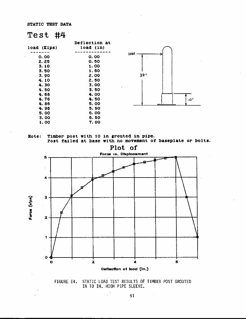
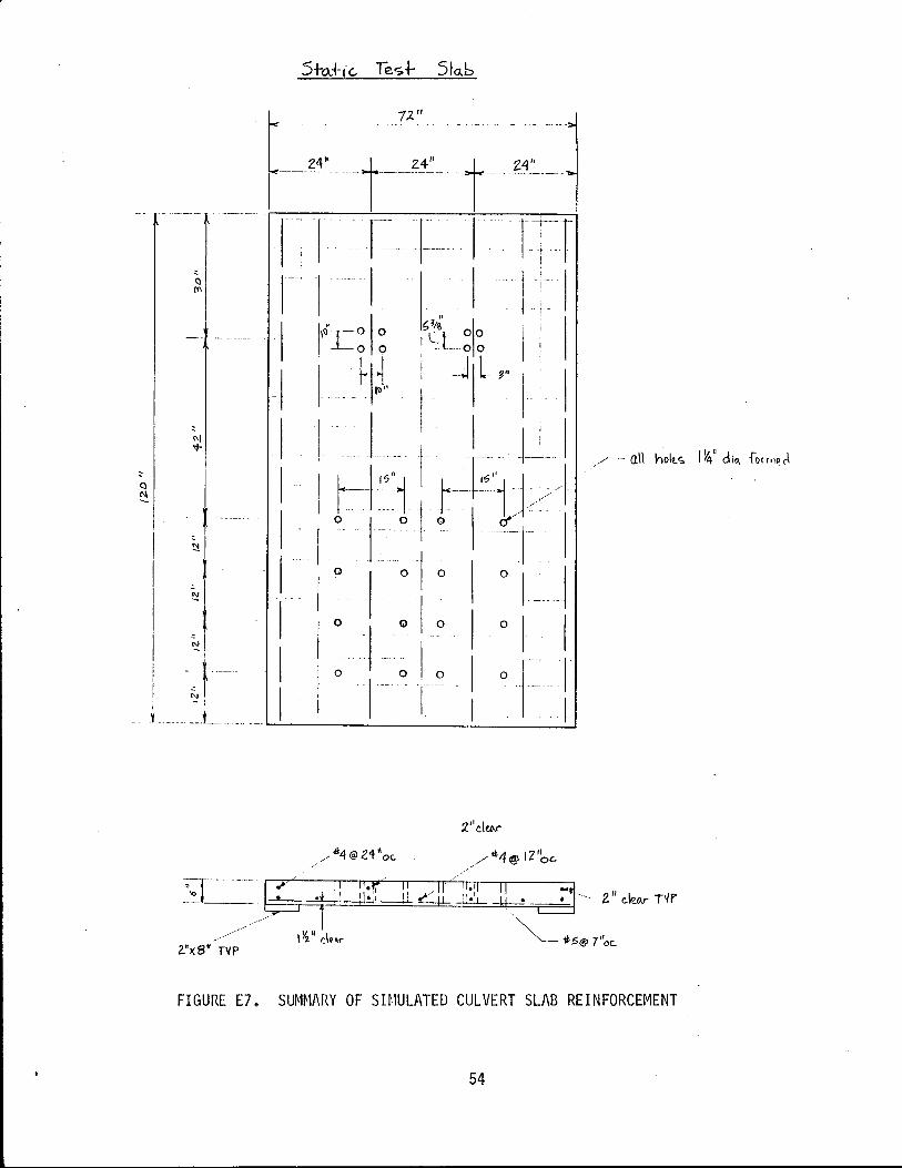
The W6 x 9 standard steel guardrail post with b10ckout was fitted with a steel base plate and bolted to the simulated culvert slab as shown by Figure 12. The 6 in. thick culvert slab was reinforced as a typical Texas culvert slab (Appendix E). The centers of the posts were located 30 in. from the outer edge of the culvert. This design should not crack the culvert slab. Static load test results of this post (without soil fill) is shown by Figure 13. Failure was by yielding and then by local buckling of the compression flange. Damaged post could relatively easily be replaced by bolting on a new post. Additional load test results and simulated culvert slab details are presented in Appendix E.
Figure 14 presents the results of an analysis of how the guard fence post load capacity would change with different soil fill depths. The 18 in. soi 1 fi 11 depth was chosen for this test because the load capacity is low (about 8.5 kips) and the probability of the car tire snagging a post highest with low fill depths.
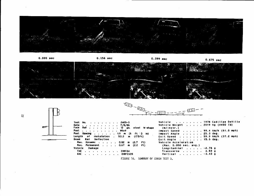
Crash Test 3. Figure 15 shows the modified guard fence No.3 and car before and after crash test 3. The 4450 1 b Cadi 11 ac Devi 11e impacted the guard fence at 61.8 mph and 25.3° angle. The car was smoothly redirected as intended. The maximum rail deflection was 2.7 ft and four posts were severely damaged.
This test and modified guard fence No.3 was very successful. With this design the guard fence can now be used over culverts even when full embedment depth of the guardrail post cannot be achieved.
17
10"
1"x 1 1/2" slotted holes 3 1/4" 1 3/4"
=-T~ 3/8" -lr++~:::'--- ~
!-+-i---+-+ ......
.. .. ....
.. .. ... (\I
-0= 0 .. -.. CI) .... !C') .. 0 'Co... :
o
1 1/4" formed or drilled holes
'- " Min.
1--3 118"
W-beam guardfence 8'-3" poat apacing
W8x9x 14" spacer or W8x8.5x 14"
3/4" ~A307 bolts with washers Length Is slab thickness +2"
10"x8"x5/8" A38 steel plate
Culvert Slab
. 8"x8"x1/4" A38 steel plate with 15/18" & holes
FIGURE 12. DETAIL OF STEEL GUARDFENCE POST AND ATTACHMENT TO CULVERT SLAB.
18
STATIC TEST RESULTS
Test #1
load
" 39
Rote: W6x9 steel post Ro £ailure or bending o£ baseplates or bolts. Failure due entirely to bending in post.
Plot of 7
B v -~
" 5 /
-" "' D. -.::I. ...... • e 3 0 II.
2
1
I / t I I
0 o 2 B
'19
FIGURE 13. STATIC LOAD TEST RESULTS FOR GUARD FENCE POST USED IN CRASH TEST 3.
~ ........ I I I "-~ I I ~ , ~ .. """ _____ +- P~~+ 2021..£ohe:2;'=-~
""'--- I ------- I ............... -~ .- ....,..---Post + So;l Cohes;on1essl
20 30
SOIL riLL DEPTH (tn.)
FIGURE 14. ANALYSIS OF GUARD FENCE POST LOAD CAPACITY FOR VARIOUS SOIL FILL DEPTHS.
40
Before
FIGURE 15. MODIFIED GUARD FENCE NO.3 AND CAR BEFORE AND AFTER CRASH TEST 3.
After
'" '"
0.000 Bec 0.156 sec
Test No. Date Face Rail Post Post Spacing Length of Installation Beam Rail Deflection
!tax. Dynamic !tax. Permanent
Vehicle Damage TAE SAE
2405-3 7/8/86
0.399 sec
trB-fH3 - - -=:==-:c
Vehicle Vehicle Weight
12 gao steel W-shape (w/instr.) W6x9 Impact Speed
1.9 m (6 ft -3 in) Impact Angle 53.3 m (175ft) Exit Speed
Exit Angle 0.82 m (2.7 ft) Vehicle Acceleration 0.67 m (2.2 ft) ("ax. 0.050 sec. avg. )
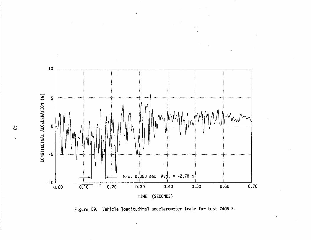
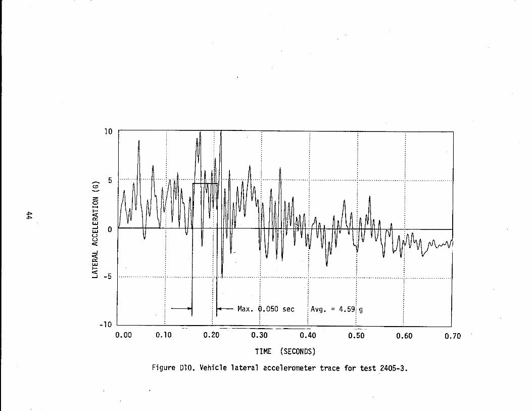
Longitudinal 01RFQ4 Transverse 01RFES35 Vertical
FIGURE 16. SUMMARY OF CRASH TEST 3.
1978 Cadi Ilae DeVille 2019 kg (4450 I b)
99.4 km/h (61. 8 mph) 25.3 deg. 59.9 km/h (3,7.2 mph) 15.6 deg.
-2.78 g 4.59 g
-3.43 g
SUMMARY AND CONCLUSIONS
The culvert-mounted Modified Guard Fence No. 3 design meets all crash test performance requi rements. The new guard fence smoothly redi rected a 2019 kg (4450 lb) vehicle traveling 99.4 km/hr (61.8 mph) and impacting the rail at an angle of 25.3 degrees. This guard fence system does not have the transition problem that the presently required rigid system does because it is flexible along its entire length.
This new guard fence system is also cheaper than using more rigid bridge rails. The new system has an approximate installation cost of $17 per ft as opposed to the $35 per ft cost of typical T10l steel bridge rail.
23
REFERENCES
1. Standard Specifications for Highway Bridges, Thirteenth Edition, American Association of State Highway and Transportation Officials, Washington, D.C., 1983.
2. Ross, H. E., Jr., Kohutek, T. L., and Pledger, J., "Guide for Selecting, Locating, and Designing Traffic Barriers," Report No. FHWA-RD-76-503, Federal Highway Administration, Washington. D.C., Feb. 1976.
3. Dewey, J. F., Jeyapa1an, J. K., Hirsch, T. J., and Ross, H. E., "A Study of the Soi 1-Structure I nteracti on Behavi or of Hi ghway Guardrail Post," Research Report No. 343-1, Texas Transportati on Institute, Texas A~M University, College Station, Texas, July 1983.
4. Eggers, D. W., Hirsch, T. J., and Ross, H. E., "Strength of Guardrail Post in Rock, Research Report No. 343-1 Supplement, Texas Transportation Institute, Texas A&M University, College Station, Texas, Sept. 1984.
5. Eggers, D. W. and Hirsch, T. J., "The Effects of Embedment Depth, Soil Properties, and Post Type on the Performance of Highway Guardrail Posts," Research Report 405-1, Texas Transportation Institute, Texas A&M University, College Station, Texas, Aug. 1986.
6. Michie, Jarvis 0., "Recommended Procedures for the Safety Performance Evaluation of Highway Appurtenances," NCHRP Report 230, Transportation Research Board, National Research Council, Washington, D.C., Mar. 1981.
7. Arnold, Althea and Hirsch, T. J., "Bridge Deck Designs for Railing Impacts," Research Report 295-1F, Texas Transportation Institute, Texas A&M University, College Station, Texas, Nov. 1983.
24
N CJ'1
APPENDIX A
GLOSSARY From Reference 2.
Area of Concern- An object or roadside condition that warrants shielding by a traffic barrier.
Barrier Warranl- A criterion that identifies an area of concern which should be shielded by a traffic barrier. The criterion may be a function of relative safety. economics. etc .• or a combination of factors.
Bridge Rail - A longitudinal barrier whose primary function is to prevent an errant vehicle from going over the side of the bridge structure.
Clear Zone- That roadside border area, starting at the edge of the traveled way, available for safe use by errant vehicles. Establishment of a minimum width clear zone implies that rigid objects and certain other hazards with clearances less than the minimum width should be removed, relocated to an inaccessible position or outside the minimum clear zone, remodeled to make safely traversable or breakaway, or shielded.
Clearance- Lateral distance from edge of traveled way to a roadside object or feature.
Crash Cushion - A traffic barrier used to safely shield fixed objects or other hazards .from approximately head-on impacts by errant vehicles. Examples are sandfilled plastic barrels, water-filled tubes, vermiculite concrete cartridges, and steel drums.
Crash worthy Ba"ier- One that can be impacted by a vehicle at or below the anticipated operating speed of the roadway with low probability of serious injury to the vehicle's occupants.
Experimental Barrier- One that has performed satisfactorily in full-scale crash tests and promises satisfactory in-service performance.
Impact Angle- For a longitudinal barrier, it is the ~ngl~ between. a tangent to' the face of the barrier and a tangent to the vehIcle s path at Impact. For a crash cushion, it is the angle between the axis of symmetry of the crash cushion and a tangent to the vehicle's path at impact.
Length of Need- Total length of a longitudinal barrier, measured with respect to centerline of roadway needed to shield an area of concern.
Longitudinal Barrier- A barrier whose primary functions are to prevent ~netration and to safely redirect an errant vehicle away from a roadsIde or median hazard. The three types of longitudinal barriers are roadside barriers, median barriers, and bridge rails.
Median Ba"ier- A longitudinal barrier used to prevent an errant vehicle from crossing the portion of a divided highway separating the traveled ways for traffic in opposite directions.
Operating Speed - The highest speed· at which reasonably prudent drivers can ~e expected to operate vehicles on a section of highway un~er low traffIC densities and good weather conditions. This speed may be hIgher or lower than posted or legislated speed limits or nominal design speeds where align-
iv
ment, surface, roadside development, or other fealures affect vehicle operation.
Operational Barrier- One that has performed satisfactorily in full-scale crash tests and has demonstrated satisfactory in-service performance.
Research and Development Barrier- One that is in the development stage and has had insufficient full-scale tests and in-service performance to be classified otherwise.
Roadside Ba"ier- A longitudinal barrier used to shield hazards located within an established minimum width clear zone. It may also be used to shield hazards in extensive areas between the rcadways of a divided highway. It may occasionally be used to protect pedestrians or "bystanders" from vehicular traffic.
Roadway- The portion of a highway, including shoulders, for vehicular lise.
Shy Distance- Distance from the edge of the traveled way beyond which a roadside object will not be perceived as an immediate hazard. by the typical driver, to the extent that he will change his vehicle's placement or speed.
Traffic Barrier- A device used to shield a hazard that is located on the roadside or in the median, or a device used to prevent crossover median accidents. As defined herein, there are four classes of traffic barriers, namely, roadside barriers, median barriers, bridge rails, and crash cushions.
Traveled Way- The portion of the roadway for the movement of vehicles, exclusive of shoulders and auxiliary lanes .
v
APPENDIX B •• UIUOI ctaUf 1/01' _ .... .-d few SftOr, (SO' or -.J
NC1'IOftt of "IGF at "". lIMIt ........
..... "',. .n 'M plOM 6'·3" IOQC'", mo, ... UM' 011 "" o .. ,..fteom (tt',,", a trotflc tao. ttanOpctlftti eftCJ ot "I!IGF' pICo:.d Oft rMO..,. WI,tI OM-way "OH"'::"":OO~'::'.:::.':::"::"=-________ •
ANCHOR OR SPLICE BOLT "eo NUT POST SOL T : $ .. ft,IO' .. cut I ... ,ff'
( ~.' "'1 bonl "OVI". for T'"'"ftCll ConNCtOr I
Ie 0: I CI ':':
I -:Gt.""'":.. t
i ~:. .... 'O: I c:a.. 0 ~
it Pel' Sln~K~~:-I_ --,._
RAIL SPLICE
I
.:. 0".1;''''' -A' T'ott,to
TIll IUCT I'OSITUIII 0' Q;AII:I racE SIIAU " AS 1_ u.s ....... tM! ~ oro AS 1I1UCTt~ BY lU !:lIC1"U~. "~oUI) rntl SIlAl.~ It ltAlli51~'OIIED 1\1. _nt ~IOII "'iJI O"IIIPI GIiAatI ratl. oa STI!1Cn.'U IAIl.lJo., N> 5~ USIMIIU 0lI P!MIII,
.uTIIlCII'TIO!IO'T1!E~nlllAll.ll.IIIDC1l ... ntr:IlUMIIPlllCtM¥.r.""IIIIDI~ !tT1lD 1: :IZ 0lI a fOOt 'iO,m;Ao!. I.DCTIIS WITtI POST IOLT SLOH r.:- C*1IG:1"10II HI P'IIIIS.
3, .... n SIIAU. IE or I"",ICIPI UJI;nt TO ana TIl ... Tn JUU. TII'CUU, Of" TIll IIt.'I _ 110) _nwr,,,".I:'fOIIOI:.
4, T1I: TOIl OP TIll: ~I)W, jIIIQIOl POSI AIiD AU. nm. PlTTI .. s ,...,.. IIIAU. ar. ~\,"lZlD • IIIWUII."IIOPIO".uI_.
), IMPIC SOLID IOCIt IS Illco.,',rnaD Ol II1II:11 _ C!I TIll ,~. TIll 1II&111~n. or TIll -.:t~ SIIIoU. U ."'_IMULI I: I~OIb. "1111 JACltrlLl.'liI. IlUoLl JE 111:"11 .. COllUIOllI.Z'~ 'VoJlIIAo!.. UII DIIIDMrlCT DD'TII SMo\IJ. .t l '_6~ 01 lIOII: .u IIII1CIED If lU IIICII&&J;, IlNaU 'Off> Sll.-l.i.1OO1 UsrftllCCIIICIUl,
CIICIIIII IIILI. H '"11111D 10 MXDIiIIIA"I"I c;a:.u roa:, 'TRLPOSTSStw.LKII.OCIDOI":. "_',)OII_,OtTULlPllCUltw,l.lEtiEDII'tllntu _TS, ~P P .... TtI s...u II .-.wIDlD U I~ .. n 1~lal .nn I'OIIU.
""0 IUCIDtT ~J.:.aD FDa II SPK"UD WIIIII!U I" nil I'UIII, • '" • '" • 14' ntrATC nlGD ".cu OP 'WoCIII PIli! SItALI. ., rlllllllTll YDOII P'IIIU,
~""I.ZSSO'l1lUlll"''''"TM!PlA''S.r.I.''''''nIICI;F'UCEIII)I'"I1II''CUCI,,''''a:a'''AIIoU,Il IUICIIED 0'.', ~o IlIAT "nil PAC! III a:1. !$ LOCIonn OII£CT~' II.UIII 011 1Dl:SO TIll 'o\CI. 0' UIo,
Figure 06. Vehicle lateral accelerometer trace for test 2405-2.
40
20 100 Hz Fil ter
-e 10 ................................................................................................. , ....... "',' z o ...... ~ 0:: LLI ..J LLI U 0 U .:c ..J 0:( U ...... I-0:: LLI :>
. fI\, IMJ ~ M) ~ A ~ !f'III, ~A • O~iV+ff~--~~~~**r+~~~~~~~~~. __ ~~A~r.v~~/~V~v~~ __ v __ ~ __ ~ V\
N N j~ ~ I~, i
: :
................•..................•................... \.i ........................ i ........................ i ........................ · ....................... .