. INTRODUCTIONadially polarized laser beams have received consider-ble attention in recent years [1–17]. Generation methodsnclude the use of fibers [5], sub-wavelength gratings [7],nd liquid crystals [9]. High-power radially polarizedeams have been shown to have increased efficiency inoth cutting and drilling, and to bypass thermally in-uced birefringence in laser rods [10–12]. High-powereneration of radial polarization in 1 �m solid-state la-ers has been achieved intra-cavity by exploiting theeated laser rod’s own thermally induced birefringence13–15] or by using multilayer polarization gratings16,17]. Extra-cavity generation has been achieved by these of specially designed optical elements such as a spi-ally variable-retarder [4,17].
Increased power from a rod-based resonator requiresigher pumping levels. At such pump levels, higher-orderhermo-optical aberrations arise, especially the radiallyymmetric spherical aberrations [18]. While spherical ab-rrations do not influence the polarization properties of aesonator designed to produce radial polarization [19],hey have a strong influence on the beam quality andower output [20,21]. While compensation methods werenvestigated in the past [22–24], a detailed analysis of
ode structure inside an aberrated resonator was noterformed.In this work we present both experimental measure-ent and quantitative theoretical analysis of spherical
berration propagation inside a radially polarized resona-or. Such a resonator has an inherent geometrical dis-rimination between radial and azimuthal polarizations.he presence of spherical aberration inside the resonatorauses the fundamental mode of the laser to have a phasetep of almost � near the optical axis, and to have a dis-inct two-ring structure. Nevertheless, a high-power 480
operation with a relatively low M2 value of 5.4 waschieved. The extra-cavity correction of the spherical ab-rration was able to reduce M2 to 4.5, and the intra-cavity
hase correction simultaneously increased the power to00 W and reduced M2 to 3.5.
. RESONATOR CONFIGURATION ANDTABILITY ANALYSIShe laser resonator configuration is illustrated in Fig. 1.he high-power diode-pumped Nd:yttrium aluminum gar-et (Nd:YAG) rod-based pump chamber was placed be-ween flat �R=�� and concave �R=30 cm� mirrors. The di-meter of the laser rod was 8 mm, the rod length was 20.5m, and the pumped length was 15 cm. The distance be-ween the rod and the flat mirror was 40 cm �L1�, and theistance between the rod and the concave mirror was 70m �L2+L3�. At a distance of 40 cm �L2� from the rod, anperture was placed in order to filter out higher-orderodes.The stability diagram of such a resonator describing
he effect of the thermal lensing of the laser rod is de-icted in Fig. 2. There are two stability zones—one for thehermal focal length fth between 46 and 76 cm and one forth between 23 and 28.5 cm. We are interested in the sec-nd zone, denoted as Stability Zone II, because it corre-ponds to operations in higher pump powers (strongerhermal focus). The stability zone has a relative width of
28.523 =1.24. This is approximately equal to the Nd:YAGod’s thermal birefringence ratio of b= f� / fr=nr /n��1.225]. Therefore, such a resonator configuration can pro-ide an inherent geometrical discrimination between theadial and azimuthal polarizations via its stability dia-ram, when operating with either radial or azimuthal po-arization inside Stability Zone II.
. OPERATION WITHOUT PHASEORRECTION. Experimental Resultshe resonator was operated at the highest pump powerossible, near the stability limit at f =23 cm, in a
th
010 Optical Society of America
cdTstimtscae
ppmsTm4iiahr
rl
taMmerpcor
F=cssa
FfTnbI
Fp
FpI(b
Fwp
1338 J. Opt. Soc. Am. B/Vol. 27, No. 7 /July 2010 Lumer et al.
ontinuous-wave mode. The pump cavity was specificallyesigned to achieve a radially symmetric pump profile.he high degree of symmetry was achieved by usingeven horizontal diode-stacks that were close-coupled tohin (1 mm) light-guides and that protruded through slitsn a ceramic diffuse reflector. Long light-guides (5 cm) ho-
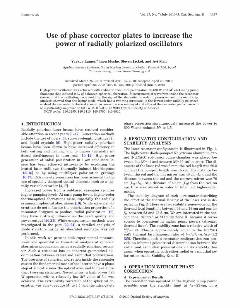
ogenized irregularities introduced by bar height varia-ions. The pump profile was measured using the diode-tacks at different orientations, and the bestonfiguration was picked and shown in Fig. 3. With suchn absorption profile, only radially symmetric optical ab-rrations arise.
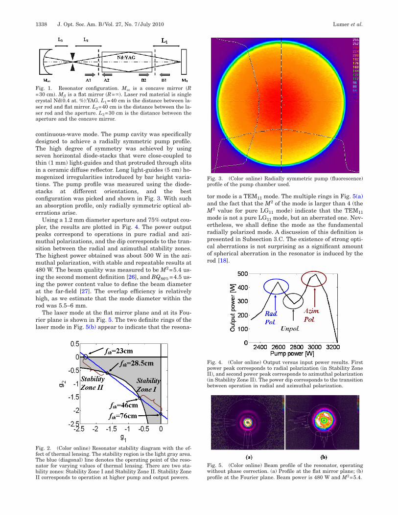
Using a 1.2 mm diameter aperture and 75% output cou-ler, the results are plotted in Fig. 4. The power outputeaks correspond to operations in pure radial and azi-uthal polarizations, and the dip corresponds to the tran-
ition between the radial and azimuthal stability zones.he highest power obtained was about 500 W in the azi-uthal polarization, with stable and repeatable results at
80 W. The beam quality was measured to be M2=5.4 us-ng the second moment definition [26], and BQ86%=4.5 us-ng the power content value to define the beam diametert the far-field [27]. The overlap efficiency is relativelyigh, as we estimate that the mode diameter within theod was 5.5–6 mm.
The laser mode at the flat mirror plane and at its Fou-ier plane is shown in Fig. 5. The two definite rings of theaser mode in Fig. 5(b) appear to indicate that the resona-
ig. 1. Resonator configuration. Mcc is a concave mirror �R30 cm�. Mfl is a flat mirror �R=��. Laser rod material is singlerystal Nd(0.4 at. %):YAG. L1=40 cm is the distance between la-er rod and flat mirror. L2=40 cm is the distance between the la-er rod and the aperture. L3=30 cm is the distance between theperture and the concave mirror.
ig. 2. (Color online) Resonator stability diagram with the ef-ect of thermal lensing. The stability region is the light gray area.he blue (diagonal) line denotes the operating point of the reso-ator for varying values of thermal lensing. There are two sta-ility zones: Stability Zone I and Stability Zone II. Stability ZoneI corresponds to operation at higher pump and output powers.
or mode is a TEM11 mode. The multiple rings in Fig. 5(a)nd the fact that the M2 of the mode is larger than 4 (the
2 value for pure LG11 mode) indicate that the TEM11ode is not a pure LG11 mode, but an aberrated one. Nev-
rtheless, we shall define the mode as the fundamentaladially polarized mode. A discussion of this definition isresented in Subsection 3.C. The existence of strong opti-al aberrations is not surprising as a significant amountf spherical aberration in the resonator is induced by theod [18].
ig. 3. (Color online) Radially symmetric pump (fluorescence)rofile of the pump chamber used.
ig. 4. (Color online) Output versus input power results. Firstower peak corresponds to radial polarization (in Stability ZoneI), and second power peak corresponds to azimuthal polarizationin Stability Zone II). The power dip corresponds to the transitionetween operation in radial and azimuthal polarization.
ig. 5. (Color online) Beam profile of the resonator, operatingithout phase correction. (a) Profile at the flat mirror plane; (b)rofile at the Fourier plane. Beam power is 480 W and M2=5.4.
nmptcarrptmrrctm
BTfssmAcrToopp
wt(fttc
wtbsl
wtbmal
tcpmflwactrflvpswcflabt
CSedsrfiedA
FtfsaTf
L
AABBc
Lumer et al. Vol. 27, No. 7 /July 2010 /J. Opt. Soc. Am. B 1339
To validate the claim that the mode is a pure mode andot a multi-mode beam, a simple interferometric experi-ent was conducted. A tilted thick glass window was
laced outside the resonator, near the concave mirror, andhe interference from its front and back surfaces is re-orded as shown in Fig. 6. The dark ellipses point out thereas where the outer ring is interfering with the innering, indicating that there is a phase relation between theings, thus confirming the assumption that the mode is aure single mode, albeit aberrated by spherical aberra-ion. The dashed lines indicate that there is an approxi-ate � phase shift between the inner and outer rings, by
unning through constructive interference in the outering and destructive interference in the inner ring. Theircular fringes arise from interference between reflec-ions from the flat and concave surfaces of the concaveirror.
. Wavefront Measurement Inside the Cavityhe beam’s wavefront was measured inside the cavity at
our different locations as described in Fig. 1. The mea-urements were taken using a Hartman–Shack wavefrontensor (HASO-32 from Imagine Optics). In all wavefronteasurements, the focusing term was subtracted. Labelsand B in Fig. 1 represent the rod planes facing the con-
ave and flat mirrors, respectively, and labels 1 and 2 rep-esent beams going into and out of the rod, respectively.he results are summarized in Table 1. The added valuef aberration was determined by a separate measurementf the aberrations of a probe beam passing through theump chamber operated at the same pump power. Thehase of an aberrated laser beam is described by
��r� = k�C2r2 + C4r4 + �higher orders��, �1�
here C2 is the focusing term, C4 is the spherical aberra-ion term, and k is the wavenumber. The peak-to-valleyPtV) value of spherical aberration is defined as the dif-erence between the maximum and minimum values ofhe phase within the effective radius of the beam, withhe focusing term subtracted. When subtracting the fo-using term, one should decompose C2 so that
ig. 6. (Color online) Interference profile of the laser mode athe concave mirror plane. The dark ellipses correspond to inter-erence between the inner and outer rings, indicating lasing at aingle transverse mode. The dashed lines indicate that there isn approximate � phase shift between the inner and outer rings.he circular fringes arise from interference between reflections
rom the flat and concave surfaces of the concave mirror.
��r� � k�C2�r2 + �C2�r
2 + C4r4��, �2�
here C2� is the subtracted term and C2� is chosen to givehe minimal PtV value within the effective radius of theeam. After such a decomposition, called the balancedpherical aberration [28], the PtV value obeys (in wave-engths)
PtV =C4R4
4�, �3�
here R is the effective radius of the beam. Notice the fac-or of 4 from the naive PtV of C4R4 /�. In this case, theeam radius at the rod plane was measured to be approxi-ately 3 mm, and thus the PtV of the balanced spherical
berration with C4=1.6�104 �m−3� is 0.3� for a wave-ength of �=1.064�.
The laser mode evolved in the resonator in such a wayhat the spherical aberration induced by the laser rod wasompensated in a round trip. Such a general behavior wasredicted in [29]. As the results in Table 1 show, the laserode propagating in the region between the rod and theat mirror had very little spherical aberration. In otherords, the beam had a nearly flat wavefront in planes B1nd B2. When the beam exited the rod in plane A2, it ac-umulated the positive spherical aberration induced byhe laser rod. As the beam propagated back to enter theod in plane A1, the spherical aberration of the beamipped its sign while maintaining the same absolutealue. Thus, as the beam propagated through the rod tolane B2 its negative spherical aberration was compen-ated by the rod and regained its approximately flatavefront. Midway between planes A2 and A1, i.e., at the
oncave mirror plane, the wavefront was approximatelyat, indicating a continuous transition between positivend negative spherical aberrations. Such an asymmetricehavior inside the resonator originated from the resona-or’s asymmetric configuration.
. Simulation of the Mode Structure Inside the Cavityimulation results for a resonator with the same param-ters are also summarized in Table 1. The simulation wasone using a matrix diagonalization calculation, de-cribed in [15], but with spherical aberration inside theesonator. The simulation assumes a radially symmetriceld amplitude, with an azimuthal dependence ofxp�±in��. The azimuthal dependence determines the or-er of the Bessel-function that appears in the propagator.s was mentioned in [15], propagation of radially and azi-
Table 1. Spherical Aberration Inside theResonator for Added Value of Aberration
of C4=1.6Ã104†m−3
‡
ocation (See Fig. 1)C4 Expt.
�m−3�C4 Sim.
�m−3�
1 −1.7�104 −1.3�104
2 1.6�104 1.3�104
1 0.13�104 −0.4�104
2 −0.12�104 0.4�104
oncave mirror −0.1�104 0.06�104
muortasmmttaspcm
nttepsimtat
fiastmgtor
4Cisde
ap
ctiahrirtpr
w[tioltsaS
pwspPuqittis
5Fpcaslf
Fae
Frt(
1340 J. Opt. Soc. Am. B/Vol. 27, No. 7 /July 2010 Lumer et al.
uthally polarized beams is equivalent to propagation ofniformly polarized beams with an azimuthal dependencef exp�±i��. The simulation gives the eigen-modes of theesonator with their eigen-values (loss per pass). Givenhe inherent geometrical discrimination between radialnd azimuthal polarizations in the resonator, it was as-umed in the simulation that lasing in radial or azi-uthal polarization occurred, and therefore the azi-uthal index n=1 was chosen. The calculations showed
hat the phases at planes B1 and B2 are more than threeimes flatter than the phases at planes A1 and A2, and ingreement with the measured results. While the mea-ured results show a more significant flattening of thehase in planes B1 and B2 than the calculations, the cal-ulated results support the general description of theode evolution inside the resonator.Only one mode had a low loss per pass ��1%�, while the
ext mode had a loss of 15% per pass, and the one afterhat had a loss of 26% per pass. Therefore, it can be saidhat the matrix diagonalization calculation predicts op-ration in a single transverse mode. The intensity andhase (focusing removed) of the mode in plane B2 ishown in Fig. 7. The two-ring pattern with low intensitynner ring and high intensity outer ring in Fig. 7(a)
atches the measured result in Fig. 5(b). The phase ofhe mode, shown in Fig. 7(b), is quite flat except for anbrupt step of about 0.86� at the intensity minima be-ween the two rings.
Despite the two-ring pattern of the laser mode, it is theundamental radially polarized mode of the resonator, ast is the lowest-order lasing mode. The two-ring patternnd phase step are a result of the spherical aberration in-ide the resonator, causing the eigen-modes of the resona-or to differ significantly from the Laguerre–Gaussianodes of free space. The simulation results show, to-
ether with the interferometric measurement in Fig. 6,hat it is not correct to identify the laser mode as a high-rder mode or as an incoherent superposition of unaber-ated TEM01 and TEM11 modes.
. EXTRA-CAVITY PHASE CORRECTIONorrecting spherical aberration intra-cavity was shown to
mprove the performance [22–24], even when using atatic corrector. Such an intra-cavity correction will beiscussed in Section 5. The addition of a phase correctinglement inside the resonator does, however, introduce an
ig. 7. (a) Intensity and (b) phase of the laser mode at plane B2s obtained from resonator simulations with added spherical ab-rration. Intensity minima correspond to a 0.86� phase step.
dditional source of sensitivity. Therefore, extra-cavityhase correction was explored.Extra-cavity phase correction is possible in our case be-
ause of the nature of the spherical aberration propaga-ion inside the resonator. As shown in Table 1, the modenside the resonator has regions with positive, negative,nd zero spherical aberrations. Assuming that the modeas the same beam quality at every position inside theesonator, it is reasonable to further assume that flatten-ng the phase in a certain phase-aberrated plane wouldesult in the improvement of the beam quality. Imaginghe rod plane A2 to outside the cavity and correcting thehase using a spherical aberration corrector (SAC) couldesult in such a phase flattening.
The phase corrector used was a pair of spherical lensesith short focal length (40 mm), previously discussed in
22]. Such a SAC introduces negative spherical aberra-ion, opposite in sign to the positive spherical aberrationnduced by the laser rod. Careful alignment is needed inrder to avoid the addition of unwanted focusing by theenses. Using the concave mirror as the output coupler ofhe resonator, imaging plane A2 outside the cavity istraightforward. By adjusting the magnification of the im-ging, an exact spherical aberration correction using theAC could be achieved.Figure 8 shows the experimentally measured phase at
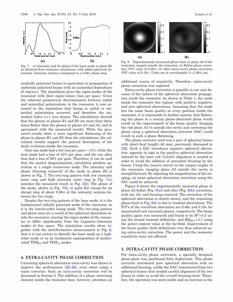
lane A2 before [Fig. 8(a)] and after [Fig. 8(b)] correction,ith tip, tilt, and focusing removed. The correction of the
pherical aberration is clearly shown, and the remaininghase front in Fig. 8(b) is due to residual aberrations. ThetV’s of the wavefront aberration are 0.46� and 0.18� forncorrected and corrected phases, respectively. The beamuality again was measured and found to be M2=4.5 us-ng the second moment definition, and BQ86%=3.7 usinghe power content value at the far-field. Improvement ofhe beam quality (both definitions) was thus achieved us-ng extra-cavity correction. The power and the resonatorensitivity were not affected.
. INTRA-CAVITY PHASE CORRECTIONor intra-cavity phase correction, a specially designedhase-plate was purchased from Asphericon. This phaseorrector introduced pure spherical aberration with nodditional focusing, unlike the SAC (constructed from twopherical lenses) that needed careful alignment of the twoenses in order to avoid the overall focusing term. There-ore, the operation was more stable and an increase in the
ig. 8. Experimentally measured phase front at plane A2 of theesonator, imaged outside the resonator. (a) Before phase correc-ion (PtV value of 0.46�); (b) after extra-cavity phase correctionPtV value of 0.18�). Units are in wavelengths ��=1.064 �m�.
oqmAtrtts
aWgbBTirsv
6OdaaflrelTatmrmr
aiiatr
R
1
1
1
1
1
1
1
1
1
P
NEI
FwpM
Lumer et al. Vol. 27, No. 7 /July 2010 /J. Opt. Soc. Am. B 1341
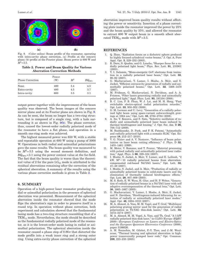
utput power together with the improvement of the beamuality was observed. The beam images at the concaveirror plane and at its Fourier plane are shown in Fig. 9.s can be seen, the beam no longer has a two-ring struc-
ure, but is composed of a single ring, with a halo sur-ounding it as shown in Fig. 9(b). The phase corrector,hus, caused the lowest-order radially polarized mode ofhe resonator to have a flat phase, and operation in amooth one-ring mode was achieved.
The highest measured power was 650 W, with a stablend repeatable operation at 600 W using a pump of 3000. Operations in both radial and azimuthal polarizations
ave the same results. The beam quality was measured toe M2=3.5 using the second moment definition, andQ86%=3.1 using the power content value at the far-field.he fact that the beam quality is worse than the theoret-
cal value of 2 for the pure LG01 mode is attributed to theesidual aberrations remaining after the correction of thepherical aberration. A summary of the results using thearious phase correction methods is given in Table 2.
. SUMMARYperation of a high-power laser resonator producing ra-ial or azimuthal polarization in the presence of sphericalberration was presented. Measurement of the sphericalberration inside the resonator showed that the modeips the aberration’s sign in order to preserve itself in aound trip. In operation without phase correction, bothxperiment and calculation showed that the fundamentalasing mode has a two-ring structure resembling that of aEM11 mode. Nevertheless, the mode should be describeds the fundamental radially polarized mode of the resona-or, as it is the lowest-order mode lasing in radial or azi-uthal polarization. The spherical aberration inside the
esonator caused a phase step of 0.86� that distorted theode profile into a weak inner ring and a strong outer
ing. Using extra-cavity phase correction of the spherical
Table 2. Power and Beam Quality for VariousAberration Correction Methods
hase CorrectionPower
(W) M2 BQ86%
one 480 5.4 4.5xtra-cavity 480 4.5 3.7
ntra-cavity 600 3.5 3.1
ig. 9. (Color online) Beam profile of the resonator, operatingith intra-cavity phase correction. (a) Profile at the concavelane; (b) profile at the Fourier plane. Beam power is 600 W and
2=3.5.
berration improved beam quality results without affect-ng the power or sensitivity. Insertion of a phase correct-ng plate inside the resonator improved the power by 25%nd the beam quality by 35%, and allowed the resonatoro extract 600 W output beam in a smooth albeit aber-ated TEM01 mode with M2=3.5.
EFERENCES1. Q. Zhan, “Radiation forces on a dielectric sphere produced
by highly focused cylindrical vector beams,” J. Opt. A, PureAppl. Opt. 5, 229–232 (2003).
2. R. Dorn, S. Quabis, and G. Leuchs, “Sharper focus for a ra-dially polarized light beam,” Phys. Rev. Lett. 91, 233901(2003).
3. Y. I. Salamin, “Mono-energetic GeV electrons from ioniza-tion in a radially polarized laser beam,” Opt. Lett. 32,90–92 (2007).
4. G. Machavariani, Y. Lumer, I. Moshe, A. Meir, and S.Jackel, “Efficient extracavity generation of radially and azi-muthally polarized beams,” Opt. Lett. 32, 1468–1470(2007).
5. M. Fridman, G. Machavariani, N. Davidson, and A. A.Friesem, “Fiber lasers generating radially and azimuthallypolarized light,” Appl. Phys. Lett. 93, 191104 (2008).
6. B. C. Lim, P. B. Phua, W. J. Lai, and M. H. Hong, “Fastswitchable electro-optical radial polarization retarder,”Opt. Lett. 33, 950–952 (2008).
7. G. M. Lerman and U. Levy, “Generation of a radially polar-ized light beam using space-variant subwavelength grat-ings at 1064 nm,” Opt. Lett. 33, 2782–2784 (2008).
8. A. Ito, Y. Kozawa, and S. Sato, “Selective oscillation of ra-dially and azimuthally polarized laser beam induced bythermal birefringence and lensing,” J. Opt. Soc. Am. B 26,708–712 (2009).
9. M. Bashkansky, D. Park, and F. K. Fatemi, “Azimuthallyand radially polarized light with a nematic SLM,” Opt. Ex-press 18, 212–217 (2010).
0. V. G. Niziev and A. V. Nesterov, “Influence of beam polar-ization on laser beam cutting efficiency,” J. Phys. D 32,1455–1461 (1999).
1. M. Meier, V. Romano, and T. Feurer, “Material processingwith pulsed radially and azimuthally polarized laser radia-tion,” Appl. Phys. A 86, 329–334 (2007).
2. I. Moshe, S. Jackel, A. Meir, Y. Lumer, and E. Leibush, “2kW, M2�10 radially polarized beams from aberration-compensated rod-based Nd:YAG lasers,” Opt. Lett. 32,47–49 (2007).
3. I. Moshe, S. Jackel, and A. Meir, “Production of radially orazimuthally polarized beams in solid-state lasers and theelimination of thermally induced birefringence effects,”Opt. Lett. 28, 807–809 (2003).
4. M. S. Roth, E. W. Wyss, H. Glur, and H. P. Weber, “Genera-tion of radially polarized beams in a Nd:YAG laser with selfadaptive overcompensation of the thermal lens,” Opt. Lett.30, 1665–1667 (2005).
5. G. Machavariani, Y. Lumer, I. Moshe, A. Meir, S. Jackel,and N. Davidson, “Birefringence-induced bifocusing for se-lection of radially or azimuthally polarized laser modes,”Appl. Opt. 46, 3304–3310 (2007).
6. M. A. Ahmed, A. Voss, M. M. Vogel, and T. Graf, “Multilayerpolarizing grating mirror used for the generation of radialpolarization in Yb:YAG thin-disk lasers,” Opt. Lett. 32,3272–3274 (2007).
7. M. A. Ahmed, M. M. Vogel, A. Voss, and Th. Graf, “A 1-kWradially polarized thin-disk laser,” in CLEO/Europe (EQEC2009)—European Conference on Lasers and Electro-Opticsand the European Quantum Electronics Conference (2009),paper 5196626.
8. A. M. Bonnefois, M. Gilebrt, P.-Y. Thro, and J.-M. Weul-ersse, “Thermal lensing and spherical aberration in high-power transversally pumped laser rods,” Opt. Commun.259, 223–235 (2005).
1
2
2
2
2
2
2
2
2
2
2
1342 J. Opt. Soc. Am. B/Vol. 27, No. 7 /July 2010 Lumer et al.
9. Y. Lumer, I. Moshe, A. Meir, Y. Paiken, G. Machavariani,and S. Jackel, “Effects of thermally induced aberrations onradially and azimuthally polarized beams,” J. Opt. Soc. Am.B 24, 2279–2286 (2007).
0. I. Buske and U. Wittrock, “Diffraction analysis of aberratedlaser resonators,” Appl. Phys. B 83, 229–233 (2006).
1. J. Bourderionnet, A. Brignon, J.-P. Huignard, and R. Frey,“Influence of aberrations on fundamental mode of highpower rod solid-state lasers,” Opt. Commun. 204, 299–310(2002).
2. I. Moshe, S. Jackel, and A. Meir, “Correction of sphericaland azimuthal aberrations in radially polarized beams fromstrongly pumped laser rods,” Appl. Opt. 44, 7823–7827(2005).
3. A. Montmerle Bonnefois, M. Gilbert, P.-Y. Thro, D. Farcage,and J.-M. Weulersse, “Novel method to improve the perfor-mance of Nd:YAG high-power, low divergence lasers using apassive compensation of the spherical aberration inside the
resonator,” in Solid-State Lasers XIV: Technology and De-vices, H. J. Hoffman and R. K. Shori, eds., Proc. SPIE 5707,362–369 (2005).
4. G. D. Love, Adaptive Optics for Industry and Medicine, 2nded. (World Scientific, 2000).
5. I. Moshe and S. Jackel, “Influence of birefringence-inducedbifocusing on optical beams,” J. Opt. Soc. Am. B 22, 1228–1235 (2005).
6. A. E. Siegman, “New developments in laser resonators,” inOptical Resonators, D. A. Holmes, ed., Proc. SPIE 1224,2–14 (1990).
7. H. Weber, “Some historical and technical aspects of beamquality,” Opt. Quantum Electron. 24, S861–S864 (1992).
8. V. N. Mahajan, Aberration Theory Made Simple, Vol. TT6 ofSPIE Tutorial Text Series (SPIE, 1991).
9. P. A. Bélanger and C. Paré, “Optical resonators usinggraded-phase mirrors,” Opt. Lett. 16, 1057–1059 (1991).