1600 IEEE TRANSACTIONS ON COMPONENTS, PACKAGING AND MANUFACTURING TECHNOLOGY, VOL. 2, NO. 10, OCTOBER 2012
Use of Al2O3–Cu/Water Hybrid Nanofluid inan Electronic Heat Sink
Ponnusamy Selvakumar and Sivan Suresh
Abstract— Cooling of electronic components is important asdemand for reduced component size and the increased heatgeneration rate cause the heat flux to increase. Liquid-cooledheat sinks work better than air-cooled heat sinks due to theimproved heat transfer capability of liquids over air. If thethermal properties of the liquids are further improved, theperformance of the heat sinks can be increased in terms oftheir capacity of heat removal at reduced size. In this paper, thethermal properties of water are altered by adding Al2O3–Cunanocomposite powder. This nanocomposite powder issynthesized in a thermochemical route followed by a hydrogenreduction technique. The synthesized nanocomposite powder ischaracterized by X-ray diffraction, scanning electron microscopy,and energy-dispersive spectroscopy. Al2O3–Cu/water hybridnanofluid is prepared and tested in a thin-channeled copperheat sink of overall dimensions 59 × 59 × 12.6 mm. The effectof hybrid nanofluid in the enhancement of convective heattransfer and pressure drop is studied. The experimental resultsdemonstrate that the convective heat transfer coefficient of theheat sink is increased significantly when hybrid nanofluid is usedas the working fluid compared with water. The rise in pumpingpower with the use of hybrid nanofluid compared with water isless than the rise in the convective heat transfer coefficient.
Index Terms— Al2O3–Cu/water hybrid nanofluid, convectiveheat transfer coefficient, interface temperature, pressure drop,pumping power.
NOMENCLATURE
A Exposed heat transfer area of the water block (m2).A1 Total surface area of the thin channels.A2 Inside surface area of the block other
than channel area.Cp Specific heat (J/kg K).D Orifice diameter (m).h Convective heat transfer coefficient (W/m2 K).k Thermal conductivity (W/m K).m Mass flow rate (kg/s).Nu Nusselt number, hD/k.Pr Prandtl number, μcp/k.q Actual heat flux (W/m2).Q Heat input (W).Re Reynolds number, 4m/πdμ.
Manuscript received September 10, 2011; revised July 3, 2012; acceptedJuly 3, 2012. Date of publication September 4, 2012; date of current versionSeptember 28, 2012. This work was supported by the Council of Scientific andIndustrial Research, CSIR Sanction Letter 22 (0484)/09/EMR-II, November10, 2009. Recommended for publication by Associate Editor M. Arik uponevaluation of reviewers’ comments.
Color versions of one or more of the figures in this paper are availableonline at http://ieeexplore.ieee.org.
Digital Object Identifier 10.1109/TCPMT.2012.2211018
T Temperature (°C).V̇ Volume flow rate (m3/s).
GREEK SYMBOLS
ϕ Volume concentration (%).�P Pressure drop in heat sink (Pa).μ Dynamic viscosity (N-s/m2).
ρ Density (kg/m3).�T Temperature difference between the inlet
fluid and the interface (°C).
SUBSCRIPTS
f Fluid.fm Fluid mean.i Interface.in Inlet.nf Nanofluid.out Outlet.s Solid phase.w Water block (heat sink).
I. INTRODUCTION
AS THE demand for miniaturized high-performance elec-tronic components increases, the heat flux produced
by the electronic components during its functioning alsoincreases. The heat flux has to be removed efficiently forthe reliability and long life of the electronic components.Excess temperature is the primary reason for the failureof electronic components [1]. If the heat dissipated to thesurrounding area is less than the heat produced, then the tem-perature of the components will increase, causing performancedeterioration and damaging the components. Functioning ofelectronic components at high temperatures may also generatenoise because of the rise in free electron movement. Thetemperature between the components case and the heat sinkis called the interface temperature. The maximum allow-able interface temperature is decided at the design stage bythe components manufacturer. When the operating interfacetemperature exceeds the maximum allowable temperature,the number of failures tremendously increases [2]. In mostelectronic equipment, the cooling system has to maintain theinterface temperature below 85 °C for better performance,reliability, and lifetime of the system. The conventional air-cooled heat sinks have reached their cooling capacity limitsas the heat flux in the electronic components is very highcompared with earlier electronic systems [3]. If air is replacedby liquids, the heat removal capacity of the heat sinks canbe increased. The advantages of liquids in cooling the elec-tronic components over air are: 1) very high heat capacity
SELVAKUMAR AND SURESH: USE OF Al2O3–Cu/WATER HYBRID NANOFLUID IN AN ELECTRONIC HEAT SINK 1601
and 2) increased thermal conductivity that would increase theconvective heat transfer coefficient [4]. When compared withthe size of the air-cooled heat sink, the size of the liquid-cooledheat sinks is appreciably small, which is most desirable for thepresent electronic components’ thermal management systems.
The performance of a liquid cooling system can further beimproved by enhancing the thermal conductivity of liquids.This enhancement in thermal conductivity of the conventionalheat transfer fluids such as water or ethylene glycol can beachieved by dispersing nanoscale solid particles into them.The improved thermal conductivity of the heat transfer fluidswill improve the convective heat transfer capability and will behelpful in developing a high-capacity compact cooling system.Suspending micrometer-sized particles in the conventionalheat transfer fluids was tried by Ahuja [5]. Heat transferfluids suspended with micrometer-sized particles had numberof drawbacks such as erosion, poor stability, clogging inmicrochannels, and high pressure drop. Choi [6] engineerednanofluid in 1995 at Argonne National Laboratory, Argonne,IL, with an objective of developing a new class of heat transferfluid with enhanced thermal properties. He reported that thereis a possibility for doubling convective heat transfer usingnanofluids without much rise in pumping power. It is interest-ing to note here that for doubling the heat transfer, pumpingpower will have to be increased by 10 times without anymodification in the thermal properties of the heat transfer fluid.Lee et al. [7] prepared Al2O3- and CuO-based nanofluids withwater and ethylene glycol as the base fluids and measured theirthermal conductivities. They found from their study that thereis a significant increase in thermal conductivity of nanofluidscompared with base fluids. Eastman et al. [8] prepared copper-based nanofluids in one-step method by producing coppernanoparticles and simultaneously dispersing them in ethyleneglycol. They reported that there is 40% increase in effectivethermal conductivity of the copper or ethylene glycol nanofluidwith 0.3% volume concentration. Keblinski et al. [9] explainedthat Brownian motion of the particles, molecular level layeringof the liquid over the surface of the particle, the ballisticnature of heat transport in the nanoparticles, and particleclustering are the possible mechanisms for improved heattransfer characteristics of nanofluids.
Yoo et al. [10] prepared nanofluids by dispersing differentnanoparticles (TiO2, Al2O3, Fe, and WO3) in DI water usingtwo-step method and measured thermal conductivity usingtransient hot wire apparatus. They compared the thermalconductivities of different nanofluids and studied the factorsthat affect them. They suggested that the surface-to-volumeratio is a key factor in determining thermal conductivity. Itwas also reported that there is a need to develop new theoriesfor predicting the thermal conductivity on the basis of stabilityof suspended nanoparticles, size of the particles, and viscosityof the base fluids. Fotukian and Nasr Esfahany [11] studiedexperimentally the effect of Al2O3/water nanofluids of lowvolume concentrations in a plain tube under turbulent flowconditions. They used nanofluids of volume concentrations<0.2% and the Reynolds number was varied from 5180to 32 000. They observed from their experimental resultsthat for the nanofluid of 0.054% volume concentration, the
enhancement in convective heat transfer is 48% compared withwater at a particular Reynolds number of 10 000. They alsoobserved that increasing the volume concentration of nanopar-ticle did not show remarkable enhancement in heat transfer.They measured the pressure drop of water and nanofluidand observed 30% increase in pressure drop compared withwater for the nanofluid volume concentration of 0.135% ata Reynolds number of 20 000. The increased heat transfer intheir work is attributed to expulsion of nanoscale particles fromthe wall to the bulk flow. Kalteh et al. [12] studied the con-vective heat transfer characteristics of Al2O3/water nanofluidin a wide rectangular channel heat sink of size 94.3 × 28.1 ×580 mm. The microchannels were made using a silicon waferwith glass layers. They found from their experimental andnumerical analysis that Nusselt number in the heat sinkincreases with increase in Reynolds number and particlevolume concentration of the nanofluid and decrease in par-ticle size. They also compared the experimental results withthe numerical results and observed a deviation of 12.61%.Sun et al. [13] studied the thermal conductivity of Ar–Cunanofluid confined in a nano-sized thin channel by equi-librium molecular dynamics through Green–Kubo formula.Their simulation results show that the vibration of nano-sized particles in the direction along the channel height isprevented because of the existence of solid boundaries andthus the thermal conductivity of the confined nanofluid isanisotropic. It is found that anomalous increase in thermalconductivity perpendicular to the channel height direction,which is attributed to the interactions between the fluid atomsand the atoms of the wall.
Lelea [14] conducted conjugate heat transfer numericalanalysis to study the effect of Al2O3/water nanofluid in amicrochannel heat sink in the laminar flow regime throughconsidering the viscous dissipation effect. It is reported thatthe heat transfer enhancement increases with increase inparticle loading and enhancement decreases with increase inparticle diameter. It is also found from the numerical resultsthat when the viscous heating effect is not considered, thenumerical analysis underestimates the heat transfer coefficientof nanofluid by 30% in the case of cooling and overestimatesby 20% for heating. Lelea et al. [15] analyzed numericallythe effect of nanofluid on heat transfer enhancement in amicrotube through accounting the viscous dissipation effect.Higher heat transfer coefficient is observed in the entranceregion.
Limited literature is available for this paper of convectiveheat transfer in the electronic heat sinks using nanofluids.Nguyen et al. [16], using a commercially available liquid-cooled heat sink, studied the heat transfer performance ofAl2O3/water nanofluid with different volume concentrationsand particle size. They showed that the addition of nanoparti-cles in the base fluid increases the convective heat transfercoefficient of heat sink and there is a maximum of 40%rise in convective heat transfer coefficient compared withthat of base fluid with a particular volume concentration of6.8%. Gherasim et al. [17] experimentally investigated theheat transfer performance of Al2O3/water nanofluid througha radial flow cooling device and showed that the Nusselt
1602 IEEE TRANSACTIONS ON COMPONENTS, PACKAGING AND MANUFACTURING TECHNOLOGY, VOL. 2, NO. 10, OCTOBER 2012
number increases with volume concentration and Reynoldsnumber, but it decreases with increase in spacing betweenthe heated plate and the disk. In these two previous studies[16], [17], the pressure drops associated with the use ofnanofluids are not presented. Roberts and Walker [18] verifiedthe convective heat transfer enhancement in a plain tube shownby Lai et al. [19] using Al2O3/water nanofluid under constantheat flux boundary condition. They also conducted experi-ments using Al2O3/water nanofluid in an electronic heat sink.An enhancement of 20% in thermal conductance has beenreported for the nanofluid containing alumina nanoparticles ofsize 20–30 nm.
Escher et al. [20] evaluated the potential benefits of nanoflu-ids for cooling electronics systems with aqueous suspensionsof silica nanoparticles of high concentrations up to 31%.The Nusselt number was extracted from the experimentalresults and compared with theoretical predictions consideringthe change of fluids bulk properties. As the deviation was<10% between the experiments and the predictions, theydemonstrated that standard correlations can be used to estimatethe convective heat transfer of nanofluids. The specific thermo-physical properties of the coolant and their impact on the heatsink performance were studied. Finally, it was demonstratedthat the relative thermal conductivity enhancement must belarger than the relative viscosity increase to gain a sizeableperformance benefit. Furthermore, they showed that it wouldbe preferable to increase the volumetric heat capacity of thefluid instead of increasing its thermal conductivity. Betz et al.[21] conducted experiments in microchannel heat sinks withsegmented flow. They observed an increase in Nusselt numbercompared with single phase flow in a heat sink of overalldimension 25 × 25 mm. The maximum pressure drop in theheat sink, however, was ∼20 kPa. Also Copeland et al. [22]explained that heat sinks with microchannels in parallel flowfashion is experiencing very high pressure drop because of thenarrow channel size and high flow rate.
In our previous work [23], we studied the effect ofCuO/water nanofluids in an electronic heat sink and observeda significant rise in convective heat transfer coefficientwith very low rise in pumping power. Most of the heattransfer studies using nanofluids have considered the oxidenanoparticles because of their superior stability characteris-tics. Metal nanoparticles have attracted the researchers lesswhen compared with oxides because of poor stability despitehigh thermal conductivity. Alumina and copper possess thedesired stability and higher thermal conductivity, respectively.Jena et al. [24] and Niihara et al. [25] have synthesizedCu–Al2O3 nanocomposites in a thermochemical method fol-lowed by hydrogen reduction technique. They used the nitratesof aluminum and copper as the starting precursor materials. Inthis paper, Al2O3–Cu hybrid nanoparticles have been synthe-sized using thermochemical method and hydrogen reductiontechnique. The hybrid nanofluid is formulated with a vol-ume concentration of 0.1% by dispersing specified amountof synthesized Al2O3–Cu hybrid nanoparticles in DI waterto investigate the effect of the flow rate on the interfacetemperature and convective heat transfer coefficient. The flowin the heat sink involves impingement at the center continued
Fig. 1. XRD pattern of synthesized Al2O3–Cu hybrid particles.
by flow through thin channels and then over the plain surfaces.The effect of hybrid nanofluid in enhancing the heat transferin the heat sink comprising all the three flow natures is studiedin this paper. We have also studied the rise in pressure dropvalues due to the inclusion of nanoscale solid particles in thewater and it is compared with that of DI water.
II. EXPERIMENTAL
A. Preparation and Characterization of Hybrid Nanoparticles
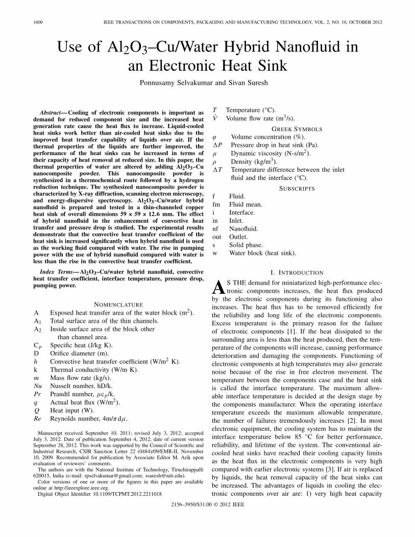
Mixture of aluminum oxide and copper oxide wassynthesized by thermochemical method. The synthesizednanoparticle mixture was then used to obtain the stablecombination of alumina and copper nanoparticles. For this,soluble nitrates of aluminum and copper (Al(NO3)3 × 9H2Oand Cu(NO3)2 × 3H2O) were used as the precursors. Watersolution of both the nitrates was prepared in such a way thatthe final proportions of alumina and copper oxide would be90:10. The prepared solution was spray dried at 180 °C toobtain the precursor powder. The collected powder after spraydrying was heated at 900 °C for 1 h in air atmosphere to obtainstable alumina and copper oxide mixture. The obtained oxidesof aluminum and copper were heated to 400 °C in hydrogenatmosphere for 1 h using a tubular furnace. Copper oxide isreduced to copper, and alumina remains stable. The powderwas ball milled for 1 h to obtain a homogenous mixture ofalumina and copper. The powder XRD of the synthesizedparticles was carried out using a Bruker AXS D8 advanceX-ray diffractometer by Cu kα1 radiation in the range of10°–80°. The reflections in the XRD pattern (Fig. 1) wereidentified corresponding to the tetragonal phase of Al2O3and cubical copper nanoparticles using joint committee onpowder diffraction standards. The average grain size of thehybrid particles was calculated to be 17 nm using Scherrerformula. The scanning electron microscopic characterization[using JSM 6390LV scanning electron microscope (SEM)] ofthe prepared hybrid nanopowders is shown in Fig. 2, whichshows that the prepared nanopowders are in the form of minuteagglomerates. Hence it is understood that the agglomeratesmust be broken by means of ultrasonication before the powdersare used in the heat transfer studies.
SELVAKUMAR AND SURESH: USE OF Al2O3–Cu/WATER HYBRID NANOFLUID IN AN ELECTRONIC HEAT SINK 1603
Fig. 2. SEM photograph of synthesized Al2O3–Cu hybrid particles at amagnification of 20 000×.
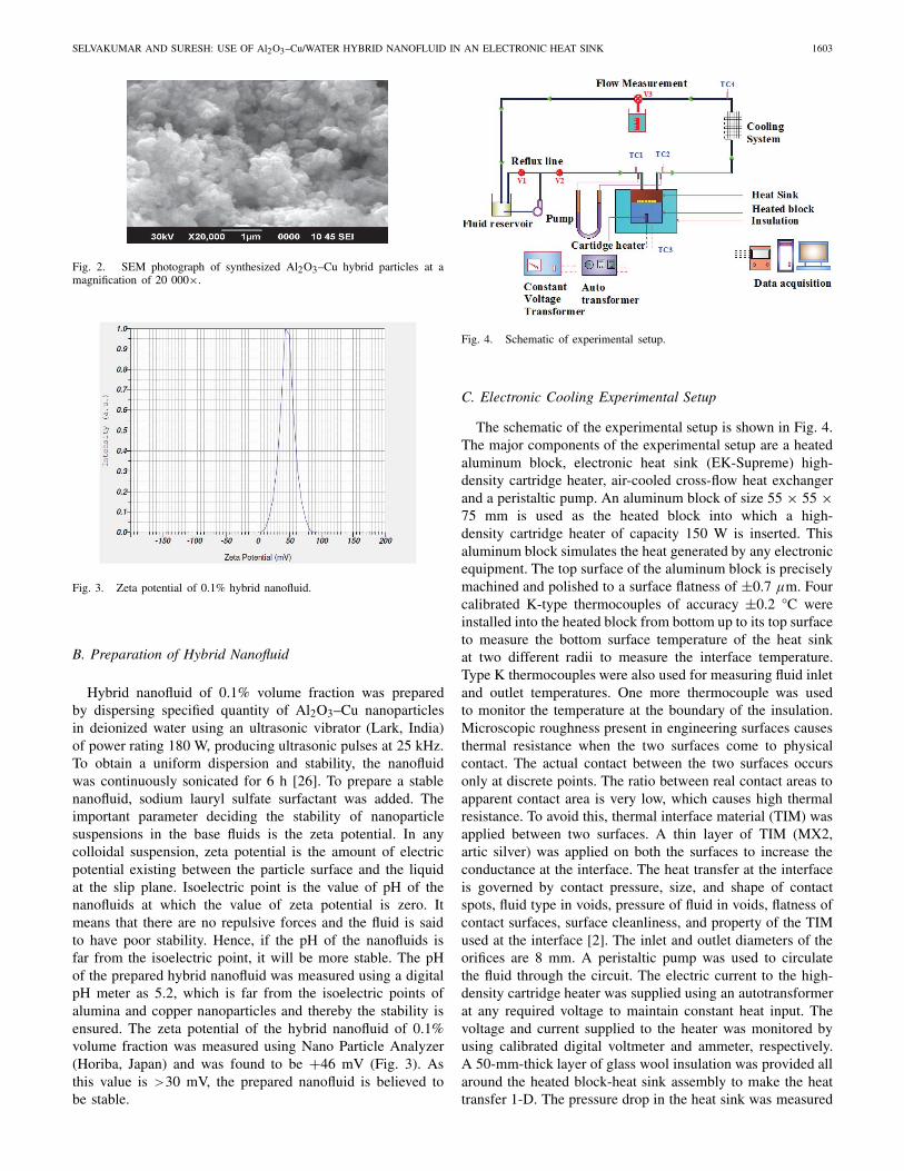
Fig. 3. Zeta potential of 0.1% hybrid nanofluid.
B. Preparation of Hybrid Nanofluid
Hybrid nanofluid of 0.1% volume fraction was preparedby dispersing specified quantity of Al2O3–Cu nanoparticlesin deionized water using an ultrasonic vibrator (Lark, India)of power rating 180 W, producing ultrasonic pulses at 25 kHz.To obtain a uniform dispersion and stability, the nanofluidwas continuously sonicated for 6 h [26]. To prepare a stablenanofluid, sodium lauryl sulfate surfactant was added. Theimportant parameter deciding the stability of nanoparticlesuspensions in the base fluids is the zeta potential. In anycolloidal suspension, zeta potential is the amount of electricpotential existing between the particle surface and the liquidat the slip plane. Isoelectric point is the value of pH of thenanofluids at which the value of zeta potential is zero. Itmeans that there are no repulsive forces and the fluid is saidto have poor stability. Hence, if the pH of the nanofluids isfar from the isoelectric point, it will be more stable. The pHof the prepared hybrid nanofluid was measured using a digitalpH meter as 5.2, which is far from the isoelectric points ofalumina and copper nanoparticles and thereby the stability isensured. The zeta potential of the hybrid nanofluid of 0.1%volume fraction was measured using Nano Particle Analyzer(Horiba, Japan) and was found to be +46 mV (Fig. 3). Asthis value is >30 mV, the prepared nanofluid is believed tobe stable.
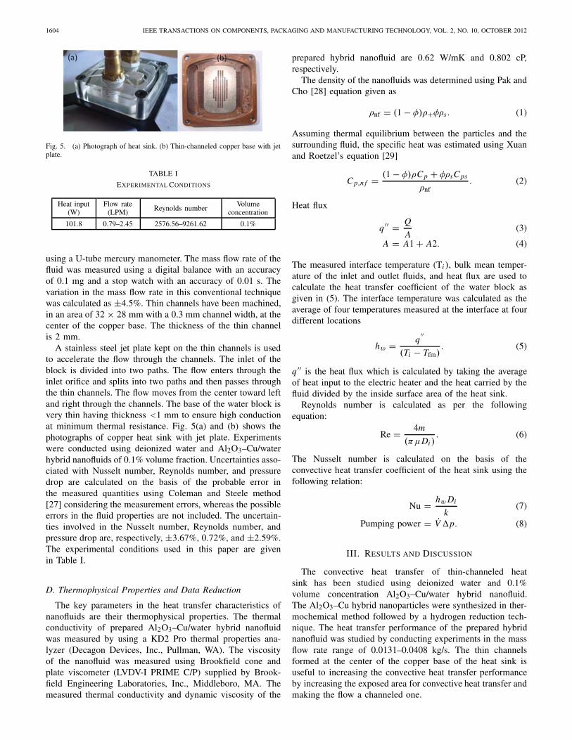
Fig. 4. Schematic of experimental setup.
C. Electronic Cooling Experimental Setup
The schematic of the experimental setup is shown in Fig. 4.The major components of the experimental setup are a heatedaluminum block, electronic heat sink (EK-Supreme) high-density cartridge heater, air-cooled cross-flow heat exchangerand a peristaltic pump. An aluminum block of size 55 × 55 ×75 mm is used as the heated block into which a high-density cartridge heater of capacity 150 W is inserted. Thisaluminum block simulates the heat generated by any electronicequipment. The top surface of the aluminum block is preciselymachined and polished to a surface flatness of ±0.7 μm. Fourcalibrated K-type thermocouples of accuracy ±0.2 °C wereinstalled into the heated block from bottom up to its top surfaceto measure the bottom surface temperature of the heat sinkat two different radii to measure the interface temperature.Type K thermocouples were also used for measuring fluid inletand outlet temperatures. One more thermocouple was usedto monitor the temperature at the boundary of the insulation.Microscopic roughness present in engineering surfaces causesthermal resistance when the two surfaces come to physicalcontact. The actual contact between the two surfaces occursonly at discrete points. The ratio between real contact areas toapparent contact area is very low, which causes high thermalresistance. To avoid this, thermal interface material (TIM) wasapplied between two surfaces. A thin layer of TIM (MX2,artic silver) was applied on both the surfaces to increase theconductance at the interface. The heat transfer at the interfaceis governed by contact pressure, size, and shape of contactspots, fluid type in voids, pressure of fluid in voids, flatness ofcontact surfaces, surface cleanliness, and property of the TIMused at the interface [2]. The inlet and outlet diameters of theorifices are 8 mm. A peristaltic pump was used to circulatethe fluid through the circuit. The electric current to the high-density cartridge heater was supplied using an autotransformerat any required voltage to maintain constant heat input. Thevoltage and current supplied to the heater was monitored byusing calibrated digital voltmeter and ammeter, respectively.A 50-mm-thick layer of glass wool insulation was provided allaround the heated block-heat sink assembly to make the heattransfer 1-D. The pressure drop in the heat sink was measured
1604 IEEE TRANSACTIONS ON COMPONENTS, PACKAGING AND MANUFACTURING TECHNOLOGY, VOL. 2, NO. 10, OCTOBER 2012
Fig. 5. (a) Photograph of heat sink. (b) Thin-channeled copper base with jetplate.
TABLE I
EXPERIMENTAL CONDITIONS
Heat input(W)
Flow rate(LPM) Reynolds number
Volumeconcentration
101.8 0.79–2.45 2576.56–9261.62 0.1%
using a U-tube mercury manometer. The mass flow rate of thefluid was measured using a digital balance with an accuracyof 0.1 mg and a stop watch with an accuracy of 0.01 s. Thevariation in the mass flow rate in this conventional techniquewas calculated as ±4.5%. Thin channels have been machined,in an area of 32 × 28 mm with a 0.3 mm channel width, at thecenter of the copper base. The thickness of the thin channelis 2 mm.
A stainless steel jet plate kept on the thin channels is usedto accelerate the flow through the channels. The inlet of theblock is divided into two paths. The flow enters through theinlet orifice and splits into two paths and then passes throughthe thin channels. The flow moves from the center toward leftand right through the channels. The base of the water block isvery thin having thickness <1 mm to ensure high conductionat minimum thermal resistance. Fig. 5(a) and (b) shows thephotographs of copper heat sink with jet plate. Experimentswere conducted using deionized water and Al2O3–Cu/waterhybrid nanofluids of 0.1% volume fraction. Uncertainties asso-ciated with Nusselt number, Reynolds number, and pressuredrop are calculated on the basis of the probable error inthe measured quantities using Coleman and Steele method[27] considering the measurement errors, whereas the possibleerrors in the fluid properties are not included. The uncertain-ties involved in the Nusselt number, Reynolds number, andpressure drop are, respectively, ±3.67%, 0.72%, and ±2.59%.The experimental conditions used in this paper are givenin Table I.
D. Thermophysical Properties and Data Reduction
The key parameters in the heat transfer characteristics ofnanofluids are their thermophysical properties. The thermalconductivity of prepared Al2O3–Cu/water hybrid nanofluidwas measured by using a KD2 Pro thermal properties ana-lyzer (Decagon Devices, Inc., Pullman, WA). The viscosityof the nanofluid was measured using Brookfield cone andplate viscometer (LVDV-I PRIME C/P) supplied by Brook-field Engineering Laboratories, Inc., Middleboro, MA. Themeasured thermal conductivity and dynamic viscosity of the
prepared hybrid nanofluid are 0.62 W/mK and 0.802 cP,respectively.
The density of the nanofluids was determined using Pak andCho [28] equation given as
ρnf = (1 − φ)ρ+φρs . (1)
Assuming thermal equilibrium between the particles and thesurrounding fluid, the specific heat was estimated using Xuanand Roetzel’s equation [29]
Cp,n f = (1 − φ)ρCp + φρsCps
ρnf. (2)
Heat flux
q ′′ = Q
A(3)
A = A1 + A2. (4)
The measured interface temperature (Ti ), bulk mean temper-ature of the inlet and outlet fluids, and heat flux are used tocalculate the heat transfer coefficient of the water block asgiven in (5). The interface temperature was calculated as theaverage of four temperatures measured at the interface at fourdifferent locations
hw = q′′
(Ti − Tfm). (5)
q ′′ is the heat flux which is calculated by taking the averageof heat input to the electric heater and the heat carried by thefluid divided by the inside surface area of the heat sink.
Reynolds number is calculated as per the followingequation:
Re = 4m
(πμDi ). (6)
The Nusselt number is calculated on the basis of theconvective heat transfer coefficient of the heat sink using thefollowing relation:
Nu = hw Di
k(7)
Pumping power = V̇ �p. (8)
III. RESULTS AND DISCUSSION
The convective heat transfer of thin-channeled heatsink has been studied using deionized water and 0.1%volume concentration Al2O3–Cu/water hybrid nanofluid.The Al2O3–Cu hybrid nanoparticles were synthesized in ther-mochemical method followed by a hydrogen reduction tech-nique. The heat transfer performance of the prepared hybridnanofluid was studied by conducting experiments in the massflow rate range of 0.0131–0.0408 kg/s. The thin channelsformed at the center of the copper base of the heat sink isuseful to increasing the convective heat transfer performanceby increasing the exposed area for convective heat transfer andmaking the flow a channeled one.
SELVAKUMAR AND SURESH: USE OF Al2O3–Cu/WATER HYBRID NANOFLUID IN AN ELECTRONIC HEAT SINK 1605
A. Interface Temperature
In a real electronic system, there are three thermal resis-tances: 1) junction to case thermal resistance; 2) case toheat sink thermal resistance; and 3) heat sink to workingfluid thermal resistance. The innermost thermal resistanceis junction to case thermal resistance that depends on themethod of packaging of electronic devices inside the case andpacking and case materials. The interface thermal resistancebetween the case and the heat sink is on the basis of the TIM,the amount of pressure at the interface, and surface flatnessof surfaces in contact. The third resistance depends on theconvective heat transfer coefficient of the heat transfer fluidand the amount of surface area of heat sink. But the interfacetemperature between the case of the electronic component andthe heat sink is on the basis of the performance of the heatsink. This temperature is to be kept minimum for the reliableperformance and lifetime of the electronic component and alsoto avoid the undesirable noise generation in the electroniccomponents.
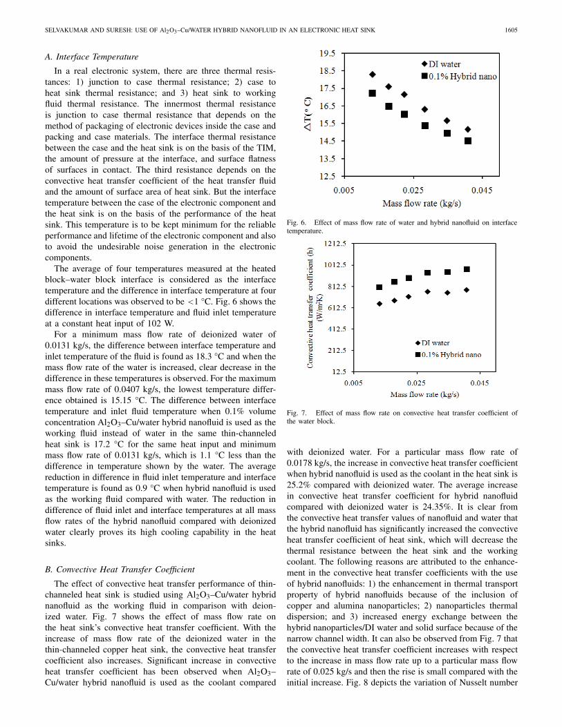
The average of four temperatures measured at the heatedblock–water block interface is considered as the interfacetemperature and the difference in interface temperature at fourdifferent locations was observed to be <1 °C. Fig. 6 shows thedifference in interface temperature and fluid inlet temperatureat a constant heat input of 102 W.
For a minimum mass flow rate of deionized water of0.0131 kg/s, the difference between interface temperature andinlet temperature of the fluid is found as 18.3 °C and when themass flow rate of the water is increased, clear decrease in thedifference in these temperatures is observed. For the maximummass flow rate of 0.0407 kg/s, the lowest temperature differ-ence obtained is 15.15 °C. The difference between interfacetemperature and inlet fluid temperature when 0.1% volumeconcentration Al2O3–Cu/water hybrid nanofluid is used as theworking fluid instead of water in the same thin-channeledheat sink is 17.2 °C for the same heat input and minimummass flow rate of 0.0131 kg/s, which is 1.1 °C less than thedifference in temperature shown by the water. The averagereduction in difference in fluid inlet temperature and interfacetemperature is found as 0.9 °C when hybrid nanofluid is usedas the working fluid compared with water. The reduction indifference of fluid inlet and interface temperatures at all massflow rates of the hybrid nanofluid compared with deionizedwater clearly proves its high cooling capability in the heatsinks.
B. Convective Heat Transfer Coefficient
The effect of convective heat transfer performance of thin-channeled heat sink is studied using Al2O3–Cu/water hybridnanofluid as the working fluid in comparison with deion-ized water. Fig. 7 shows the effect of mass flow rate onthe heat sink’s convective heat transfer coefficient. With theincrease of mass flow rate of the deionized water in thethin-channeled copper heat sink, the convective heat transfercoefficient also increases. Significant increase in convectiveheat transfer coefficient has been observed when Al2O3–Cu/water hybrid nanofluid is used as the coolant compared
Fig. 6. Effect of mass flow rate of water and hybrid nanofluid on interfacetemperature.
Fig. 7. Effect of mass flow rate on convective heat transfer coefficient ofthe water block.
with deionized water. For a particular mass flow rate of0.0178 kg/s, the increase in convective heat transfer coefficientwhen hybrid nanofluid is used as the coolant in the heat sink is25.2% compared with deionized water. The average increasein convective heat transfer coefficient for hybrid nanofluidcompared with deionized water is 24.35%. It is clear fromthe convective heat transfer values of nanofluid and water thatthe hybrid nanofluid has significantly increased the convectiveheat transfer coefficient of heat sink, which will decrease thethermal resistance between the heat sink and the workingcoolant. The following reasons are attributed to the enhance-ment in the convective heat transfer coefficients with the useof hybrid nanofluids: 1) the enhancement in thermal transportproperty of hybrid nanofluids because of the inclusion ofcopper and alumina nanoparticles; 2) nanoparticles thermaldispersion; and 3) increased energy exchange between thehybrid nanoparticles/DI water and solid surface because of thenarrow channel width. It can also be observed from Fig. 7 thatthe convective heat transfer coefficient increases with respectto the increase in mass flow rate up to a particular mass flowrate of 0.025 kg/s and then the rise is small compared with theinitial increase. Fig. 8 depicts the variation of Nusselt number
1606 IEEE TRANSACTIONS ON COMPONENTS, PACKAGING AND MANUFACTURING TECHNOLOGY, VOL. 2, NO. 10, OCTOBER 2012
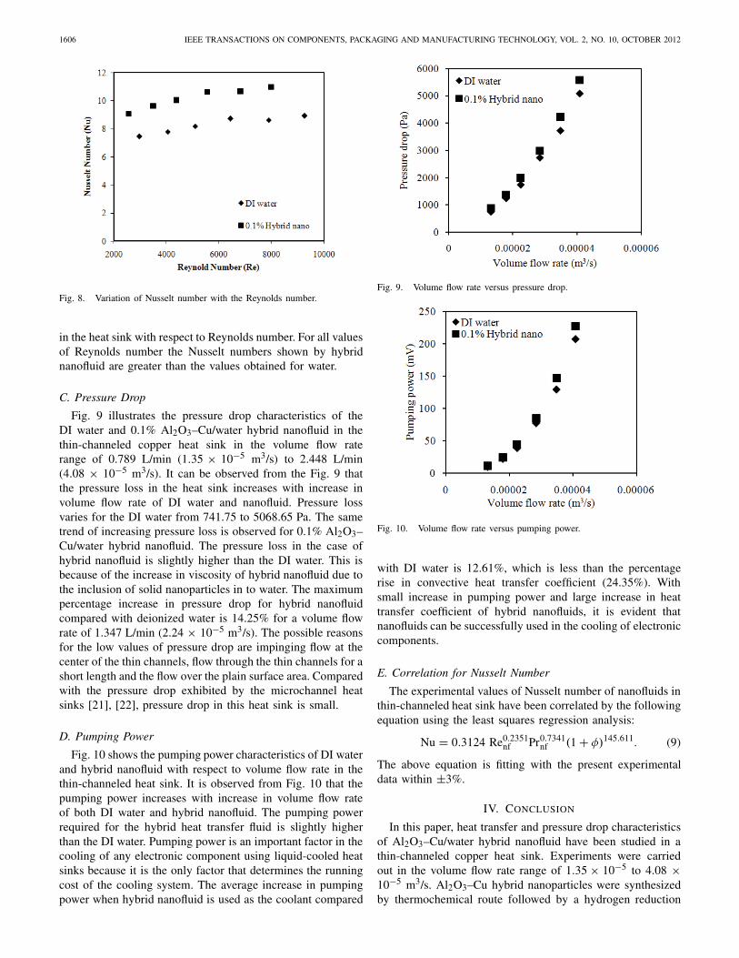
Fig. 8. Variation of Nusselt number with the Reynolds number.
in the heat sink with respect to Reynolds number. For all valuesof Reynolds number the Nusselt numbers shown by hybridnanofluid are greater than the values obtained for water.
C. Pressure Drop
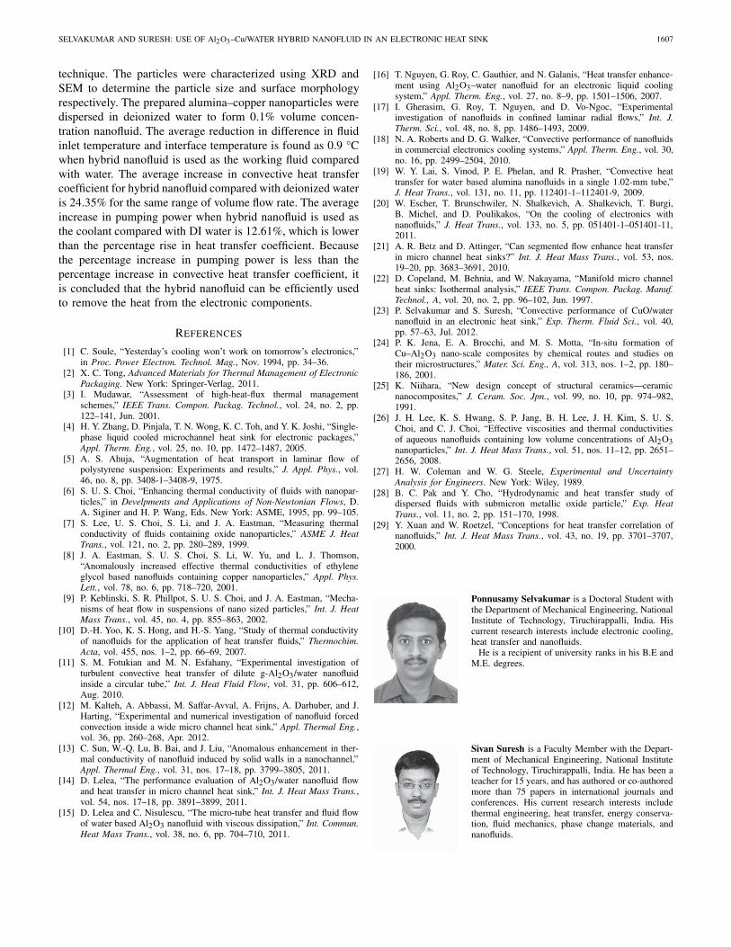
Fig. 9 illustrates the pressure drop characteristics of theDI water and 0.1% Al2O3–Cu/water hybrid nanofluid in thethin-channeled copper heat sink in the volume flow raterange of 0.789 L/min (1.35 × 10⁻⁵ m3/s) to 2.448 L/min(4.08 × 10−5 m3/s). It can be observed from the Fig. 9 thatthe pressure loss in the heat sink increases with increase involume flow rate of DI water and nanofluid. Pressure lossvaries for the DI water from 741.75 to 5068.65 Pa. The sametrend of increasing pressure loss is observed for 0.1% Al2O3–Cu/water hybrid nanofluid. The pressure loss in the case ofhybrid nanofluid is slightly higher than the DI water. This isbecause of the increase in viscosity of hybrid nanofluid due tothe inclusion of solid nanoparticles in to water. The maximumpercentage increase in pressure drop for hybrid nanofluidcompared with deionized water is 14.25% for a volume flowrate of 1.347 L/min (2.24 × 10⁻⁵ m3/s). The possible reasonsfor the low values of pressure drop are impinging flow at thecenter of the thin channels, flow through the thin channels for ashort length and the flow over the plain surface area. Comparedwith the pressure drop exhibited by the microchannel heatsinks [21], [22], pressure drop in this heat sink is small.
D. Pumping Power
Fig. 10 shows the pumping power characteristics of DI waterand hybrid nanofluid with respect to volume flow rate in thethin-channeled heat sink. It is observed from Fig. 10 that thepumping power increases with increase in volume flow rateof both DI water and hybrid nanofluid. The pumping powerrequired for the hybrid heat transfer fluid is slightly higherthan the DI water. Pumping power is an important factor in thecooling of any electronic component using liquid-cooled heatsinks because it is the only factor that determines the runningcost of the cooling system. The average increase in pumpingpower when hybrid nanofluid is used as the coolant compared
Fig. 9. Volume flow rate versus pressure drop.
Fig. 10. Volume flow rate versus pumping power.
with DI water is 12.61%, which is less than the percentagerise in convective heat transfer coefficient (24.35%). Withsmall increase in pumping power and large increase in heattransfer coefficient of hybrid nanofluids, it is evident thatnanofluids can be successfully used in the cooling of electroniccomponents.
E. Correlation for Nusselt Number
The experimental values of Nusselt number of nanofluids inthin-channeled heat sink have been correlated by the followingequation using the least squares regression analysis:
Nu = 0.3124 Re0.2351nf Pr0.7341
nf (1 + φ)145.611. (9)
The above equation is fitting with the present experimentaldata within ±3%.
IV. CONCLUSION
In this paper, heat transfer and pressure drop characteristicsof Al2O3–Cu/water hybrid nanofluid have been studied in athin-channeled copper heat sink. Experiments were carriedout in the volume flow rate range of 1.35 × 10⁻⁵ to 4.08 ×10⁻⁵ m3/s. Al2O3–Cu hybrid nanoparticles were synthesizedby thermochemical route followed by a hydrogen reduction
SELVAKUMAR AND SURESH: USE OF Al2O3–Cu/WATER HYBRID NANOFLUID IN AN ELECTRONIC HEAT SINK 1607
technique. The particles were characterized using XRD andSEM to determine the particle size and surface morphologyrespectively. The prepared alumina–copper nanoparticles weredispersed in deionized water to form 0.1% volume concen-tration nanofluid. The average reduction in difference in fluidinlet temperature and interface temperature is found as 0.9 °Cwhen hybrid nanofluid is used as the working fluid comparedwith water. The average increase in convective heat transfercoefficient for hybrid nanofluid compared with deionized wateris 24.35% for the same range of volume flow rate. The averageincrease in pumping power when hybrid nanofluid is used asthe coolant compared with DI water is 12.61%, which is lowerthan the percentage rise in heat transfer coefficient. Becausethe percentage increase in pumping power is less than thepercentage increase in convective heat transfer coefficient, itis concluded that the hybrid nanofluid can be efficiently usedto remove the heat from the electronic components.
REFERENCES
[1] C. Soule, “Yesterday’s cooling won’t work on tomorrow’s electronics,”in Proc. Power Electron. Technol. Mag., Nov. 1994, pp. 34–36.
[2] X. C. Tong, Advanced Materials for Thermal Management of ElectronicPackaging. New York: Springer-Verlag, 2011.
[3] I. Mudawar, “Assessment of high-heat-flux thermal managementschemes,” IEEE Trans. Compon. Packag. Technol., vol. 24, no. 2, pp.122–141, Jun. 2001.
[4] H. Y. Zhang, D. Pinjala, T. N. Wong, K. C. Toh, and Y. K. Joshi, “Single-phase liquid cooled microchannel heat sink for electronic packages,”Appl. Therm. Eng., vol. 25, no. 10, pp. 1472–1487, 2005.
[5] A. S. Ahuja, “Augmentation of heat transport in laminar flow ofpolystyrene suspension: Experiments and results,” J. Appl. Phys., vol.46, no. 8, pp. 3408-1–3408-9, 1975.
[6] S. U. S. Choi, “Enhancing thermal conductivity of fluids with nanopar-ticles,” in Develpments and Applications of Non-Newtonian Flows, D.A. Siginer and H. P. Wang, Eds. New York: ASME, 1995, pp. 99–105.
[7] S. Lee, U. S. Choi, S. Li, and J. A. Eastman, “Measuring thermalconductivity of fluids containing oxide nanoparticles,” ASME J. HeatTrans., vol. 121, no. 2, pp. 280–289, 1999.
[8] J. A. Eastman, S. U. S. Choi, S. Li, W. Yu, and L. J. Thomson,“Anomalously increased effective thermal conductivities of ethyleneglycol based nanofluids containing copper nanoparticles,” Appl. Phys.Lett., vol. 78, no. 6, pp. 718–720, 2001.
[9] P. Keblinski, S. R. Phillpot, S. U. S. Choi, and J. A. Eastman, “Mecha-nisms of heat flow in suspensions of nano sized particles,” Int. J. HeatMass Trans., vol. 45, no. 4, pp. 855–863, 2002.
[10] D.-H. Yoo, K. S. Hong, and H.-S. Yang, “Study of thermal conductivityof nanofluids for the application of heat transfer fluids,” Thermochim.Acta, vol. 455, nos. 1–2, pp. 66–69, 2007.
[11] S. M. Fotukian and M. N. Esfahany, “Experimental investigation ofturbulent convective heat transfer of dilute g-Al2O3/water nanofluidinside a circular tube,” Int. J. Heat Fluid Flow, vol. 31, pp. 606–612,Aug. 2010.
[12] M. Kalteh, A. Abbassi, M. Saffar-Avval, A. Frijns, A. Darhuber, and J.Harting, “Experimental and numerical investigation of nanofluid forcedconvection inside a wide micro channel heat sink,” Appl. Thermal Eng.,vol. 36, pp. 260–268, Apr. 2012.
[13] C. Sun, W.-Q. Lu, B. Bai, and J. Liu, “Anomalous enhancement in ther-mal conductivity of nanofluid induced by solid walls in a nanochannel,”Appl. Thermal Eng., vol. 31, nos. 17–18, pp. 3799–3805, 2011.
[14] D. Lelea, “The performance evaluation of Al2O3/water nanofluid flowand heat transfer in micro channel heat sink,” Int. J. Heat Mass Trans.,vol. 54, nos. 17–18, pp. 3891–3899, 2011.
[15] D. Lelea and C. Nisulescu, “The micro-tube heat transfer and fluid flowof water based Al2O3 nanofluid with viscous dissipation,” Int. Commun.Heat Mass Trans., vol. 38, no. 6, pp. 704–710, 2011.
[16] T. Nguyen, G. Roy, C. Gauthier, and N. Galanis, “Heat transfer enhance-ment using Al2O3–water nanofluid for an electronic liquid coolingsystem,” Appl. Therm. Eng., vol. 27, no. 8–9, pp. 1501–1506, 2007.
[17] I. Gherasim, G. Roy, T. Nguyen, and D. Vo-Ngoc, “Experimentalinvestigation of nanofluids in confined laminar radial flows,” Int. J.Therm. Sci., vol. 48, no. 8, pp. 1486–1493, 2009.
[18] N. A. Roberts and D. G. Walker, “Convective performance of nanofluidsin commercial electronics cooling systems,” Appl. Therm. Eng., vol. 30,no. 16, pp. 2499–2504, 2010.
[19] W. Y. Lai, S. Vinod, P. E. Phelan, and R. Prasher, “Convective heattransfer for water based alumina nanofluids in a single 1.02-mm tube,”J. Heat Trans., vol. 131, no. 11, pp. 112401-1–112401-9, 2009.
[20] W. Escher, T. Brunschwiler, N. Shalkevich, A. Shalkevich, T. Burgi,B. Michel, and D. Poulikakos, “On the cooling of electronics withnanofluids,” J. Heat Trans., vol. 133, no. 5, pp. 051401-1–051401-11,2011.
[21] A. R. Betz and D. Attinger, “Can segmented flow enhance heat transferin micro channel heat sinks?” Int. J. Heat Mass Trans., vol. 53, nos.19–20, pp. 3683–3691, 2010.
[22] D. Copeland, M. Behnia, and W. Nakayama, “Manifold micro channelheat sinks: Isothermal analysis,” IEEE Trans. Compon. Packag. Manuf.Technol., A, vol. 20, no. 2, pp. 96–102, Jun. 1997.
[23] P. Selvakumar and S. Suresh, “Convective performance of CuO/waternanofluid in an electronic heat sink,” Exp. Therm. Fluid Sci., vol. 40,pp. 57–63, Jul. 2012.
[24] P. K. Jena, E. A. Brocchi, and M. S. Motta, “In-situ formation ofCu–Al2O3 nano-scale composites by chemical routes and studies ontheir microstructures,” Mater. Sci. Eng., A, vol. 313, nos. 1–2, pp. 180–186, 2001.
[25] K. Niihara, “New design concept of structural ceramics—ceramicnanocomposites,” J. Ceram. Soc. Jpn., vol. 99, no. 10, pp. 974–982,1991.
[26] J. H. Lee, K. S. Hwang, S. P. Jang, B. H. Lee, J. H. Kim, S. U. S.Choi, and C. J. Choi, “Effective viscosities and thermal conductivitiesof aqueous nanofluids containing low volume concentrations of Al2O3nanoparticles,” Int. J. Heat Mass Trans., vol. 51, nos. 11–12, pp. 2651–2656, 2008.
[27] H. W. Coleman and W. G. Steele, Experimental and UncertaintyAnalysis for Engineers. New York: Wiley, 1989.
[28] B. C. Pak and Y. Cho, “Hydrodynamic and heat transfer study ofdispersed fluids with submicron metallic oxide particle,” Exp. HeatTrans., vol. 11, no. 2, pp. 151–170, 1998.
[29] Y. Xuan and W. Roetzel, “Conceptions for heat transfer correlation ofnanofluids,” Int. J. Heat Mass Trans., vol. 43, no. 19, pp. 3701–3707,2000.
Ponnusamy Selvakumar is a Doctoral Student withthe Department of Mechanical Engineering, NationalInstitute of Technology, Tiruchirappalli, India. Hiscurrent research interests include electronic cooling,heat transfer and nanofluids.
He is a recipient of university ranks in his B.E andM.E. degrees.
Sivan Suresh is a Faculty Member with the Depart-ment of Mechanical Engineering, National Instituteof Technology, Tiruchirappalli, India. He has been ateacher for 15 years, and has authored or co-authoredmore than 75 papers in international journals andconferences. His current research interests includethermal engineering, heat transfer, energy conserva-tion, fluid mechanics, phase change materials, andnanofluids.