Industrial Scale Ltd Phone: 306-949-1322 Fax: 306-949-8842 Toll Free: 1-800-661-1588 Training Levels for Weigh Scale Service Technicians WI 1 Rev 4-10.08.2015 Approved by: JTH Page 1 of 4 Achievement of a 3A drivers license at any time. The learner is expected to write and pass the air brake test and achieve his learner’s license on his own. ISL will cover the cost to write the test once and get the physical. Once this is achieved the learner at ISL’s expense will be sent to driving school for one week and take the Class 3A driving test at the end of the week. Level 1 (up to the first 6 months of employment) At Level 1 the employee gains an understanding of the scale industry and is introduced to the Quality System while gaining the skills necessary to service our customers: Week 1, the objective is to expose the new technician to the scale industry and ISL’s forms. Introduce and review ISL’s Quality Policy and the ISO Management System. Introduce and review ISL’s Safety Manual. Ensure the tech understands his responsibilities for his safety and the safety of others. Introduce and review ISL’s Policy Manual Tab 10 and Tab 11. Teach the tech to understand and fill out the following forms accurately and consistently: Time Sheet Analysis vehicle maintenance checklists Sales order, other forms as necessary Week 2 Test and Evaluate the Skills and Abilities learned in level 1 and train as required. Ensure the above terms are understood and can be applied. Understand and operate a multimeter to test a scale and a load cell. Understand and operate a load cell simulator. Understand and perform metric conversions easily. Understand and perform the soldering of wires leaving a neat result. Understand and perform the soldering of connectors. Teach the tech to understand and apply the following terms: calibration of scales span capacity shift lbs. to kg conversion strain tolerance load cell levers digital weight indicators mechanical electro-mechanical grad size raw counts Week 3 Test and Evaluate the Skills and Abilities learned in level 2 and train as required. Ensure the above terms are understood and can be applied. Assign the tech his own tools and safety equipment. The tech is responsible to take care of all tools of Industrial Scale Ltd. and replace those tools he should lose. Teach the tech to understand and complete work orders, scale test reports, scale service checklists. Introduce the IPO’s (Inspection Procedure Outline) found in the NAWDS manual. Introduce the STP’s (Standard Test Procedures) found in the NAWDS manual. Introduce RAMS as part of testing a truck scale. How they are used and why they are used? Introduce basic troubleshooting techniques to determine whether a load cell is malfunctioning. A review of the Load Cell Handbook from Rice Lake should be beneficial at this time. Introduce, train and test the technician on using the various hoist systems for moving the test weights on the test trucks. ISL’s work instruction #3. Introduce, train and test the technician on performing routine vehicle checks for the vehicle he is driving that day (This includes form # 22, 23, 24 and 25) and restock any used parts at the end of the day form #34.
Training Levels for Weigh Scale Service Technicians WI 1 Rev 4-10.08.2015 Approved by: JTH Page 1 of 4
Achievement of a 3A drivers license at any time. The learner is expected to write and pass the air brake test and achieve his learner’s license on his own. ISL will cover the cost to write the test once and get the physical. Once this is achieved the learner at ISL’s expense will be sent to driving school for one week and take the Class 3A driving test at the end of the week. Level 1 (up to the first 6 months of employment) At Level 1 the employee gains an understanding of the scale industry and is introduced to the Quality System while gaining the skills necessary to service our customers: Week 1, the objective is to expose the new technician to the scale industry and ISL’s forms. Introduce and review ISL’s Quality Policy and the ISO Management System. Introduce and review ISL’s Safety Manual. Ensure the tech understands his responsibilities for his safety and the safety of others. Introduce and review ISL’s Policy Manual Tab 10 and Tab 11. Teach the tech to understand and fill out the following forms accurately and consistently: Time Sheet Analysis vehicle maintenance checklists Sales order, other forms as necessary Week 2 Test and Evaluate the Skills and Abilities learned in level 1 and train as required. Ensure the above terms are understood and can be applied. Understand and operate a multimeter to test a scale and a load cell. Understand and operate a load cell simulator. Understand and perform metric conversions easily. Understand and perform the soldering of wires leaving a neat result. Understand and perform the soldering of connectors. Teach the tech to understand and apply the following terms: calibration of scales span capacity shift lbs. to kg conversion strain tolerance load cell levers digital weight indicators mechanical electro-mechanical grad size raw counts Week 3 Test and Evaluate the Skills and Abilities learned in level 2 and train as required. Ensure the above terms are understood and can be applied. Assign the tech his own tools and safety equipment. The tech is responsible to take care of all tools of Industrial Scale Ltd. and replace those tools he should lose. Teach the tech to understand and complete work orders, scale test reports, scale service checklists. Introduce the IPO’s (Inspection Procedure Outline) found in the NAWDS manual. Introduce the STP’s (Standard Test Procedures) found in the NAWDS manual. Introduce RAMS as part of testing a truck scale. How they are used and why they are used? Introduce basic troubleshooting techniques to determine whether a load cell is malfunctioning. A review of the Load Cell Handbook from Rice Lake should be beneficial at this time. Introduce, train and test the technician on using the various hoist systems for moving the test weights on the test trucks. ISL’s work instruction #3. Introduce, train and test the technician on performing routine vehicle checks for the vehicle he is driving that day (This includes form # 22, 23, 24 and 25) and restock any used parts at the end of the day form #34.
Training Levels for Weigh Scale Service Technicians WI 1 Rev 4-10.08.2015 Approved by: JTH Page 2 of 4
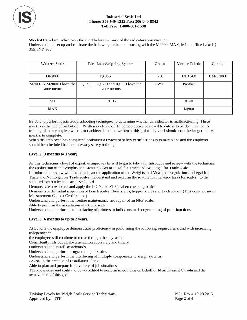
Week 4 Introduce Indicators - the chart below are most of the indicators you may see. Understand and set up and calibrate the following indicators; starting with the M2000, MAX, M1 and Rice Lake IQ 355, IND 560
Western Scale Rice LakeWeighing System Ohaus Mettler Toledo Condec
DF2000 IQ 355 I-10 IND 560 UMC 2000
M2000 & M2000D have the same menus
IQ 390 IQ 590 and IQ 710 have the same menus
CW11 Panther
M1 RL 120 8140
MAX Jaguar
Be able to perform basic troubleshooting techniques to determine whether an indicator is malfunctioning. Three months is the end of probation. Written evidence of the competencies achieved to date is to be documented. A training plan to complete what is not achieved is to be written at this point. Level 1 should not take longer than 6 months to complete. When the employee has completed probation a review of safety certifications is to take place and the employee should be scheduled for the necessary safety training. Level 2 (3 months to 1 year) As this technician’s level of expertise improves he will begin to take call. Introduce and review with the technician the application of the Weights and Measures Act to Legal for Trade and Not Legal for Trade scales. Introduce and review with the technician the application of the Weights and Measures Regulations to Legal for Trade and Not Legal for Trade scales. Understand and perform the routine maintenance tasks for scales to the standards set out by Industrial Scale Ltd. Demonstrate how to use and apply the IPO’s and STP’s when checking scales Demonstrate the initial inspection of bench scales, floor scales, hopper scales and truck scales. (This does not mean Measurement Canada Certification) Understand and perform the routine maintenance and repair of an NH3 scale. Able to perform the installation of a truck scale. Understand and perform the interfacing of printers to indicators and programming of print functions. Level 3 (6 months to up to 2 years) At Level 3 the employee demonstrates proficiency in performing the following requirements and with increasing independence the employee will continue to move through the pay scale. Consistently fills out all documentation accurately and timely. Understand and install scoreboards. Understand and perform programming of scales. Understand and perform the interfacing of multiple components to weigh systems. Assists in the creation of Installation Plans Able to plan and prepare for a variety of job situations The knowledge and ability to be accredited to perform inspections on behalf of Measurement Canada and the achievement of this goal.
Training Levels for Weigh Scale Service Technicians WI 1 Rev 4-10.08.2015 Approved by: JTH Page 3 of 4
Level 4 (not all technicians will have the ability to achieve this level) This level is a high performance, extremely knowledgeable technician with Management capabilities. This technician is fully independent, he is able to schedule his/her own work. He is able to work through challenges that are new to him/her. When given a job he is able to create his own installation plan and follow through with out assistance. Assists in the training and evaluation of scale technicians. High Level programming of weight indicators. Set up and installation of various scale systems (set points). Assists in quoting of service work. Assists in the scheduling of service work. Has knowledge of a wide variety of scales, for example belt scale, bulkweighers etc. At all levels the employee must continue to: Continue to take responsibility for ensuring that all Health and Safety requirements are met. Consistently fill out all documentation accurately and timely. Continue to perform routine vehicle checks for the vehicle he is driving that day and restock any used parts at the end of the day. Continue to take care of all tools of Industrial Scale Ltd. and replace those tools he should lose.
Skills Matrix for Weigh Scale Service Technicians Employee Acknowledgement: Please note that the skills matrix and the job descriptions are designed to be used together and in conjunction with all other procedures and processes established by the company that guide employee decision making and performance. Employees are to perform other relevant duties such as planning, reporting, paperwork, maintaining vehicles and equipment, preparing for jobs, promoting and selling the company’s services, etc. as required by management. Employees are to actively promote the expertise and services of Industrial Scale Ltd. to customers, potential customers and other business associates, etc. Employees are to act in accordance with sound business practices and high ethical standards at all times. Employees are to comply with all company and customer safety standards and work standards while on the customer’s site. Employees are to comply with all company safety standards and work standards at all times. Employees are to report any safety risks or issues, either real or perceived, within the company or the customer to their supervisor immediately. Employees are not to take risks which could jeopardize their safety or the safety of their co-workers or customers, including risks to person, property or equipment, etc. Employees are to protect the assets and equipment of Industrial Scale Ltd. and the customer at all times. Include tangible items such as tools, vehicles, inventory, etc. and intangible items such as reputation, name, certifications (ISO, Measurement Canada, etc.), goodwill, image, relationships, etc. Employees shall be prepared to leave the shop with sufficient time in order to attend customer appointments on time and on schedule. As such, the employee will be required to plan in advance, prepare vehicles and equipment and inventory for customer projects, etc. as required by management. Employees agree to abide by the company policies and procedures and to be held accountable for their performance in relation to the company policy and procedures, job descriptions and skills matrix. Employees shall attest to their commitment to these company requirements by signing their names to the respective documents. These documents will be subject to change in order to protect the interests of the company and our customers and in order to provide the highest level of services possible.
Training Levels for Weigh Scale Service Technicians WI 1 Rev 4-10.08.2015 Approved by: JTH Page 4 of 4
Training Levels
The following information is to be used by management in the assessment of the wage provided to technicians. There are two components to the wage: 1. Qualifications 2. COLA (Cost of Living Allowance); Technical Remuneration is based on qualifications achieved. There is a numerical raise attached to each qualification. For example, the achievement of a Class 3A drivers license results ins an automatic raise and the achievement of becoming a Measurement Canada inspector results in an automatic raise. The technician shall be started at a step that considers the qualification and experience of that tech. The second component comes into play if a technician does receive any new qualifications, therefore does not receive a raise, for one years time. In this case COLA (cost of living adjustment) comes into affect and is given based on an anniversary or hiring date. In regards to technicians who are fully qualified and have been with the company for a long time, wage will be looked at annually to ensure they are properly compensated. In conjunction with qualification raises and COLA requirements at every raise include: following company policies to work always in a safe and efficient manner; protecting the customer and their assets and property; protecting yourself and the company including its reputation and assets at all times; presenting yourself in a polite and professional manner; refraining from abusive or harassing behavior or language; and complying with standard company policies and procedures as indicated in the Weigh Scale Service Technician job descriptions, skills matrix, code of conduct and other company documents. Starting Wage: _______________________ Qualification Level:_________________________________ Prepared by: __________________________ Acknowledged by Employee: __________________________ Date Prepared: ________________________ Date Acknowledged: ________________________________
Identification and Storage The following instructions apply to: Identification, handling and storage of equipment (devices, parts or components of devices) when received from a supplier. Identification, handling and storage of customer equipment brought into the shop for repair. Identification, handling and storage of customer equipment to be used as part of a purchase . Industrial Scale Ltd is responsible to handle and store equipment including customer equipment in such a way as to prevent deterioration or damage. This applies to all processes from the time the items are received to such time as they are installed and inspected at the customer’s location. Definitions Industrial Scale Ltd. Label is a silver sticker with the companies name and phone number. Customer’s Equipment When the customer brings in a piece of equipment a docket is filled out with a description of the equipment and the reason that the equipment has been brought in. The docket number is written on an identification tag and attached to the piece of equipment for identification. The equipment is then moved to the designated area. If the customer supplied product is lost or damaged or is otherwise unsuitable for use a Nonconformance Report F#7 is completed and the customer is notified immediately. Equipment Received When a piece of equipment is received it is placed in the receiving area for identification. When a new piece of equipment is received to be sold directly to a customer: The package is inspected for any possible damage by the person receiving it. The Purchase order is pulled and matched to packing slip for verification. The sales/service person who ordered the equipment is notified of its arrival by the person receiving the equipment. Either the Parts Order Request Form #34 &/or the Purchase Order is labeled with the part # and any serial numbers and given to the person who ordered the equipment. An Industrial Scale Ltd. label is placed on the equipment in an area visible to the customer. Any instruction manuals are stamped with the Industrial Scale Ltd. address stamp. If the piece of equipment is not legal for trade, the “Not Legal for Trade” sticker is applied. To identify the equipment it is either tagged with the customer’s name or the customer’s name is written on the box. The device is then moved to the storage area for safekeeping. The sales/service person has the equipment tested if possible before contacting the customer to ensure it is in working condition. If the equipment is for field service work (e.g. load cells), the equipment is given to the service department for the job to be scheduled. If the scales is to be certified “Legal for Trade”, the salesperson who ordered the equipment will complete a docket . The salesperson is responsible to notify the customer of the equipment’s arrival and request delivery instructions. All correspondence with the customer is documented on the Parts Order Request or the Purchase Order. If the equipment is to be shipped, it is packaged to prevent damage and the box is labeled with an address label and waybill if applicable and moved to shipping area.
Identification and Storage WI 2 Rev 5-07.23.2010 Approved by: JTH Page 1 of 2
When a new piece of equipment is received to be inventoried: Purchase Order is pulled and matched to packing slip for verification. An Industrial Scale Ltd. label is placed on the equipment in an area visible to the customer. Any instruction manuals are stamped with the Industrial Scale Ltd. address stamp. If the piece of equipment is not legal for trade, ensure the “Not Legal for Trade” sticker is present or one is applied. The equipment is tested (if possible) to ensure it is in working condition. Some items such as load cells cannot be tested. Form 87 Scale Test Report-Verification of Equipment is completed and filed in the filing cabinet in a folder labeled “Verification of Equipment for Scales in inventory” or it is put in the box with the scale. A price sticker is placed on all equipment used in display which includes the part number, description, serial number (if applicable) and the price. All boxes are resealed, and the part number, description, serial number (if applicable) and the price are written on a sticker and applied to the box. Following identification the equipment is moved to the appropriate area depending on its intended use (e.g. inventory or display). Storage All equipment for inventory is stored in such a manner as to protect it from damage. All customer’s equipment is stored in such a manner as to protect it from damage. All equipment is stored in such a manner as to protect it from damage. Packaging Equipment requiring delivery to the customer or another location is packaged or secured in such a way as to protect it from damage. Instructions for installation are included to ensure the equipment is intact when placed into service.
Identification and Storage WI 2 Rev 5-07.23.2010 Approved by: JTH Page 2 of 2
HOW TO OPERATE WHITE (INTERNATIONAL) CARGOMASTER HOIST Make sure there are no obstructions in work area. Truck must be level in order to unload weights. Open back doors locking doors open with cargo box side clips. Ensure door handle is folded in flat preventing it from hitting the side of the cargo box. Place pylons around weight drop perimeter. Swing out hoist tracks and install lock pins. Remove hoist parking boomers. Push clutch in and engage P.T.O. in cab of truck ( If air pressure is too low, P.T.O. will not engage) WARM up P.T.O for 5 minutes in winter Set RPM @ 1000 Turn on hoist On/Off switch located in back right corner of cargo box as well as inside cargo box light if necessary. Move hoist out box and visually inspect hoist cable.
*NOTE: If there are any broken strands in cable contact supervisor immediately.*
When unloading weights operator must stand clear of weights on hoist. KEEP 5’ -10’ away from weights at all times until weights are safely on the ground. When picking up weights, ensure the crane is directly over top of the weights you are loading, ensuring the cable is straight up and down. Carefully stack weights behind truck, making sure ground is solid, stable and clean. When reloading weights make sure there is no mud, ice or debris on the bottom of the weights. Park hoist and lock in place with boomers. Let hook cradle down, sitting directly behind last set of test weights. Turn hoist and light switches off. Load pylons into truck.
Crane Operation - Cargomaster WI 3A Rev 2-09.22.2008 Approved by: JTH Page 1 of 2
HOW TO OPERATE WHITE (INTERNATIONAL) CARGOMASTER HOIST Place hoist hand control on transport hook and make sure control cable is not in weight and hook area. Pull lock pins on hoist swivel tracks and swing back into truck and lock in place and close doors. Disengage P.T.O. DO NOT DRIVE WITH P.T.O. ENGAGED. Do not back truck up with hoist swivel tracks in unload position without rear supervision.
ALWAYS PERFORM SAFETY WALK AROUND TRUCK BEFORE LEAVING SITE.
Verification of Training: By signing this document the supervisor is acknowledging he has demonstrated this proce-dure to the technician. He has then had the technician demonstrate the procedure back to him. He is satisfied the technician has the knowledge and capability to perform this procedure consistently and safely. Supervisor Printed Name: _________________________ Signature: _____________________________ Technician Printed Name: _________________________ Signature: _____________________________ The technician by signing this document agrees the training he has received is complete and he feels he can confi-dently perform this procedure with no supervision and meet all the safety requirements. Should the technician re-quire further training indicate so below with a date at which time the next training shall occur do not sign above.
Crane Operation - Cargomaster WI 3A Rev 2-09.22.2008 Approved by: JTH Page 2 of 2
HOW TO OPERATE HIAB CRANE ALWAYS Make sure there are NO OVERHEAD LINES AND/OR OBSTRUCTIONS in work area. Place pylons around weight drop perimeter. Ensure this includes the entire area in which you will be moving the weights around in to get them to their final resting place. Push clutch in and engage P.T.O. in cab of truck, set RPM @ 1000 (PTO will not engage if air pressure too low) Warm up PTO for 5 minutes in winter. Flip Switch to Dump suspension air bags. Check to make sure hydraulic bypass valve is in the correct position. IN for Crane/ OUT for Center Rams PLUG IN AND LOCK CABLED REMOTE The outrigger on the side of the truck which you are swinging the test weights from requires the outrigger to be ex-tended outward from the truck with the locking pin set. Make sure you have clearance with any over head lines or obstructions with crane extended. To get crane out of HOME position Fold-up secondary knuckle to remove from lock position. Unfold crane and push out first extension, the latch will unlock. Use 3 hook cradle to move test weights.
*** NEVER WALK UNDER CRANE AT ANY TIME. *** Always unload weights away from you. DO NOT swing weights over where you are standing. Always have test weights in your sight when moving them. Always try to keep weights close to truck when setting them in final position. Try not to move weights when crane is fully extended beside truck. Try to set weights directly behind truck and close to truck, when possible. When reloading weights make sure there is no mud, ice or debris on the bottom of the weights. When all weights are reloaded, place cradle back in mount. Remove hook and connection bolt and place in cabinet. Unfold the crane until straight, extend boom and set down into cradle. Raise outrigger rams ensuring they are in transport position, unlock them and move laterally back to transport posi-tion and confirm they are locked in transport position. Load pylons into truck.
Crane Operation - Hiab WI 3B Rev 4-09.14.2012 Approved by: JTH Page 1 of 2
Unhook cabled remote, replace plug cover and lock. Disengage PTO. DO NOT DRIVE WITH P.T.O. ENGAGED Flip switch to fill suspension air bags.
ALWAYS PERFORM SAFETY WALK AROUND TRUCK BEFORE LEAVING SITE.
USE OF SECTION RAMS
Section Rams are located between truck cab and tool box. Rams are used to provide a concentrated load on the scale to test the accuracy of the scale sections. The ram bypass valve is located on the drivers side between the truck cab and the tool box. In order for lever to operate the rams, the hydraulic bypass valve must be pulled toward operator for the rams to operate. The individual rams do not raise and lower at the same speed and operator must visually confirm the rams are raised or lowered depending on which action the operator is performing. Operator must also make sure the rams are in the proper position when in the lowered position that they are tilting in the direction of the test truck. When section testing is completed, visually confirm rams are in the transport position (completely raised) Push ram bypass valve in so crane will operate. Return to page 1 of HOW TO OPERATE HIAB CRANE for details of transport preparation.
ALWAYS PERFORM SAFETY WALK AROUND TRUCK BEFORE LEAVING SITE.
Verification of Training: By signing this document the supervisor is acknowledging he has demonstrated this procedure to the technician. He has then had the technician demonstrate the procedure back to him. He is satisfied the technician has the knowledge and capability to perform this procedure consistently and safely. Supervisor Printed Name: __________________________________________ Signature: _____________________________________________ Technician Printed Name: ___________________________________________ Signature: ______________________________________________ The technician by signing this document agrees the training he has received is complete and he feels he can confidently perform this procedure with no supervision and meet all the safety requirements. Should the technician require further training indicate so below with a date at which time the next training shall occur do not sign above.
Crane Operation - Hiab WI 3B Rev 4.09.14.2012 Approved by: JTH Page 2 of 2
Crane Operation – Effer WI 3C Rev 0 10-08-2015 Approved by: JTH Page 1 of 2 .
HOW TO OPERATE EFFER CRANE (Unit 17) ALWAYS Make sure there are NO OVERHEAD LINES AND/OR OBSTRUCTIONS in work area. Place pylons around weight drop perimeter. Ensure this includes the entire area in which you will be slinging the weights in, in order to get them to their final resting place. Push clutch in and engage P.T.O. in cab of truck, set RPM @ 1000 Note: **(PTO will not engage if air pressure too low)** Note: **In winter ensure you Warm up PTO for 5 minutes.** Check to make sure hydraulic bypass valve is in the correct position. Up for Crane/ Down for Center Rams Disengage holding pin and aluminum safety catches for outriggers , extend outriggers until pin automatically engages Turn blue knob on outrigger til cutaway portion faces inwards The outrigger on both sides of the truck require Pads to be placed under the footing and are to be lowered until truck is stabilized firmly by outriggers Make sure you have clearance with any over head lines or obstructions with crane extended. To get crane out of HOME position remove holding pin from crane and mount place holding pin in mount and secure crane should be free to Extend Fold-up secondary knuckle to remove from lock position. Unfold crane and push out first extension, the latch will unlock. Use 3 hook cradle to move test weights start by removing retaining Pin from cradle (stow pin) in mount once cradle has been properly affixed to Crane, begin safely slowly moving test weights. ****Test weights which come loose and fall have the capability for loss of life or limb always ensure weights are fully engaged on cradle and NEVER WALK UNDER CRANE AT ANY TIME. *** Always unload weights away from you. DO NOT swing weights over where you are standing. Always have test weights in your sight when moving them. Always try to keep weights close to truck when setting them in final position. Try not to move weights when crane is fully extended beside truck. Try to set weights directly behind truck and close to truck, when possible. When reloading weights make sure there is no mud, ice or debris on the bottom of the weights. When all weights are reloaded, place cradle back in Transport mount. Replace locking pin and lock in transport position . Stow Crane ensuring all three locks are utilized extension lock, secondary boom rest and finally transport pin. Raise outrigger rams ensuring they are in transport position and turn blue knobs so cutaway portion is facing outwards, unlock them and move laterally back to transport position and confirm transport pins have engaged and safety slides are firmly in place. Load pylons into truck. NH3 Rack Note there is a center loop which bolts on to rack ( Must be removed in order to transport rack on truck.) When using rack – it is lifted off or putting on truck using 1 lifting strap and clevice (2 point lifting)
Crane Operation – Effer WI 3C Rev 0 10-08-2015 Approved by: JTH Page 1 of 2 .
Take rack off truck lay on the ground then bolt center lifting hook on rack and double nut bolt, then lift on and off NH3 truck with center hook of lifting cradle.
Disengage PTO. DO NOT DRIVE WITH P.T.O. ENGAGED ALWAYS PERFORM SAFETY WALK AROUND TRUCK BEFORE LEAVING SITE. USE OF SECTION RAMS Section Rams are located between truck cab and tool box. Rams are used to provide a concentrated load on the scale to test the accuracy of the scale sections. The ram bypass valve is located on the drivers side In the First large tool box a. In order for lever to operate the rams, the hydraulic bypass valve must be inline with the hydraulic hose or pulled toward operator for the rams to operate. The individual rams do not raise and lower at the same speed and operator must visually confirm the rams are raised or lowered depending on which action the operator is performing. Operator must also make sure the rams are in the proper position when in the lowered position that they are tilting in the direction of the test truck. When section testing is completed, visually confirm rams are in the transport position (completely raised). Push ram bypass valve in so crane will operate. Return to page 1 of HOW TO OPERATE EFFER CRANE for details of transport preparation. ALWAYS PERFORM SAFETY WALK AROUND TRUCK BEFORE LEAVING SITE. Verification of Training: By signing this document the supervisor is acknowledging he has demonstrated this procedure to the technician. He has then had the technician demonstrate the procedure back to him. He is satisfied the technician has the knowledge and capability to perform this procedure consistently and safely. Supervisor Printed Name: __________________________________________ Signature: _____________________________________________ Technician Printed Name: ___________________________________________ Signature: ______________________________________________ The technician by signing this document agrees the training he has received is complete and he feels he can confidently perform this procedure with no supervision and meet all the safety requirements. Should the technician require further training indicate so below with a date at which time the next training shall occur do not sign above.
HOW TO OPERATE FLiner CRANE ALWAYS Make sure there are NO OVERHEAD LINES AND/OR OBSTRUCTIONS in work area. Place pylons around weight drop perimeter. Ensure this includes the entire area in which you will be moving the weights around in to get them to their final resting place. Push clutch in and engage P.T.O. in cab of truck, set RPM @ 1200 (PTO will not engage if air pressure too low) Warm up PTO for 5 minutes in winter. Flip Switch to Dump suspension air bags. Turn on the switch on the remote that operates the crane. The outrigger on the side of the truck which you are swinging the test weights from requires the outrigger to be ex-tended outward from the truck with the locking pin set. Turn line lock. Lower the outrigger rams until there is weight on each outrigger. Make sure you have clearance with any over head lines or obstructions with crane extended. Unfold crane. Use 2 hook cradle to move test weights. NEVER WALK UNDER CRANE AT ANY TIME. Always unload weights away from you. DO NOT swing weights over where you are standing. Always have test weights in your sight when moving them. Always try to keep weights close to truck when setting them in final position. Try not to move weights when crane is fully extended beside truck. Try to set weights directly behind truck and close to truck, when possible. When reloading weights make sure there is no mud, ice or debris on the bottom of the weights. When all weights are reloaded, place cradle back in service body, close top of service body and make sure back doors are in lock position. Fold crane, making sure main knuckle is in transport lip and extension is back in home position. Unlock line lock. Raise outrigger rams ensuring they are in transport position, unlock them and move laterally back to transport posi-tion and confirm they are locked in transport position. Flip switch to fill suspension air bags. Load pylons into truck. Turn off the switch on the remote that operates the crane.
Crane Operation - Hiab WI 3D Rev 0-10.08.2008 Approved by: JTH Page 1 of 2
Disengage PTO. DO NOT DRIVE WITH P.T.O. ENGAGED
ALWAYS PERFORM SAFETY WALK AROUND TRUCK BEFORE LEAVING SITE.
USE OF SECTION RAMS Section Rams are located between truck cab and tool box. Rams are used to provide a concentrated load on the scale to test the accuracy of the scale sections. The individual rams do not raise and lower at the same speed and operator must visually confirm the rams are raised or lowered depending on which action the operator is performing. When section testing is completed, visually confirm rams are in the transport position (completely raised) Return to page 1 of HOW TO OPERATE FLiner CRANE for details of transport preparation.
ALWAYS PERFORM SAFETY WALK AROUND TRUCK BEFORE LEAVING SITE. Verification of Training: By signing this document the supervisor is acknowledging he has demonstrated this procedure to the technician. He has then had the technician demonstrate the procedure back to him. He is satisfied the technician has the knowledge and capability to perform this procedure consistently and safely. Supervisor Printed Name: __________________________________________ Signature: _____________________________________________ Technician Printed Name: ___________________________________________ Signature: ______________________________________________ The technician by signing this document agrees the training he has received is complete and he feels he can confidently perform this procedure with no supervision and meet all the safety requirements. Should the technician require further training indicate so below with a date at which time the next training shall occur do not sign above.
Crane Operation - Hiab WI 3D Rev 0-10.08.2008 Approved by: JTH Page 2 of 2
HOW TO OPERATE UNIT #7 (2010 International) CARGO MASTER HOIST
Crane Operation – Unit 7 WI 3E Rev 0-01.10.2014 Approved by: JTH Page 1 of 2
1. Make sure there are no obstructions in the work area. 2. Perform safety walk around.The truck must be level before loading or unloading weights. 3. Open the back doors and lock them to the main body with the clips. 4. Ensure the handle is folded in so it won’t contact the cargo body. 5. Place pylons appropriately around the weight drop area. 6. Swing out hoist tracks and install lock pins.Remove hoist parking boomers. 7. Using the wireless hand held remote, press the start button.
The wireless receiver will show two lit LED’s when turned on.
The hoist is now ready for use, if needed turn on the cargo box lights. The switch is located on the driver’s side just inside the rear of the cargo area.
1. Move hoist out to the open for a cable inspection. a. **NOTE: if the cable is showing wear (broken strands) contact your supervisor
immediately.** b. **COLD WEATHER: during cold weather run the hoist up and down when empty 2 to 3
times to circulate the oil and loosen the system up.** 2. When unloading or loading weights the operator must stand clear of the weights on the hoist.
KEEP 5 to 10 feet away from the weights when they are being moved. Insure the cable is vertical when lifting weights.
3. When placing weights on any surface make sure that surface is stable, solid and clean. 4. When reloading weights back into the truck insure there is nothing stuck on the bottom (mud,
ice or other debris). 5. Store the hoist and lock with the boomers. 6. Let the hook cradle down on the floor behind the weights. 7. Pull the lock pins and store the hoist tracks. 8. Turn off hoist and lights. 9. Return hoist remote to truck cab. 10. Load pylons and close cargo doors.
HOW TO OPERATE UNIT #7 (2010 International) CARGO MASTER HOIST
Crane Operation – Unit 7 WI 3E Rev 0-01.10.2014 Approved by: JTH Page 2 of 2
11. Perform safety walk around truck before leaving site.
**NOTE: Do not move the truck with the hoist tracks in the unloading position without an outside attendant**.
Verification of training: By signing this document the supervisor is acknowledging he has demonstrated this procedure to the technician. He has then had the technician demonstrate the procedure back to him. He is satisfied the technician has the knowledge and capability to perform this procedure consistently and safely.
The technician by signing this document agrees the training he has received is complete and he feels he can confidently perform this procedure with no supervision and meet all safety requirements. Should the technician require further training indicate so below with a date at which time the next training shall occur do not sign above.
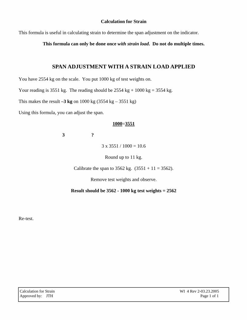
Calculation for Strain This formula is useful in calculating strain to determine the span adjustment on the indicator.
This formula can only be done once with strain load. Do not do multiple times.
SPAN ADJUSTMENT WITH A STRAIN LOAD APPLIED
You have 2554 kg on the scale. You put 1000 kg of test weights on. Your reading is 3551 kg. The reading should be 2554 kg + 1000 kg = 3554 kg. This makes the result –3 kg on 1000 kg (3554 kg – 3551 kg) Using this formula, you can adjust the span.
1000=3551 3 ?
3 x 3551 / 1000 = 10.6
Round up to 11 kg.
Calibrate the span to 3562 kg. (3551 + 11 = 3562).
Remove test weights and observe.
Result should be 3562 - 1000 kg test weights = 2562
Re-test.
Calculation for Strain WI 4 Rev 2-03.23.2005 Approved by: JTH Page 1 of 1
Use of Test Standards WI5 Rev 6-10.08.2015 Approved by: JTH Page 1 of 2
Use of Test Standards Test standards (or test weights) are certified annually by Measurement Canada as per the current version of Measurement Canada Bulletin A-2-E. Measurement Canada issues a Certificate of Designation which includes the SN (serial number) of the standard, the date it was certified and the date it expires. ISL keeps current versions of the Certificates of Designation in the Weight Inspection Certificate Binder stored in the office of the Manager of Operations. To ensure accuracy is maintained it is important to take care of the test standards as follows: Test Kits Each technician is assigned a test kit. The weights in the test kit are certified annually by Measurement Canada. Measurement Canada issues a Certificate of Designation, the original is kept in Weight Inspection Certificate Binder, copies are available on the K drive and the ISL Web site. Do not drop the kit or a test standard from the kit. Keep test standards clean. Store the individual standards in the appropriate case at all times. Hand Weights Certificates of Designation for hand weights are kept Weight Inspection Certificate Binder, copies are available on the K drive (Custpro)and the ISL Website. Do not throw or drop a hand weight. When transporting hand weights using the weight cart there is to be no more than 10 weights on the cart at a time. When transporting hand weights in a vehicle they are to be placed individually in rows as close together as possible in one layer. No stacking of the hand weights. Keep hand weights clean and free from the buildup of dirt. If using weights in a dirty environment try to make sure that the minimum numbers of weights get dirty. Clean any weights following completion of the job. When stacking hand weights for storage in the shop, hand weights are to be stacked no more than five high. All vehicles should be driven in such a manner that prevents the weights from shifting in the vehicle. Large Test Weights Certificates of Designation for large test weights are kept in the Weight Inspection Certificate Binder, copies are available on the K drive(Custpro )and the ISL Website. When stacking the large test weights place them in such a manner that prevents them from tipping. It is important to keep the large test weights free from dirt and ice buildup as this may affect the accuracy. Clean the large test weights in a car wash or with a garden hose should they become dirty. When moving the large test weights using the heavy duty test trucks make sure the weight is securely attached before moving the weights. Ensure that the large test weights are placed on a clean flat surface with the base of the weight flat on the truck floor or the large test weight may tip over. The test truck should be driven in such a manner that the large test weights will remain safely in place.
Damaged Test Standards If any test standard is found to be damaged to the extent its accuracy is in question, this test standard must not be used and must be removed from service. The Service Manager is to be notified of the damaged test standard and he will tag and isolate the test standard. The Service Manager will review the devices checked using this test standard to determine if any of the devices would require retesting.
Use of Test Standards WI5 Rev 6-10.08.2015 Approved by: JTH Page 2 of 2
Borrowed Test Standards If borrowed test standards are to be used a copy of the Certificate of Designation for the standards must be examined to ensure it is current. A copy of the Certificate of Designation must accompany any paper work for the device where the standards have been used. Before using the borrowed standards they must be visually inspected for intact seals, damage, cleanliness or other discrepancy which may affect the accuracy of the standard. The borrowed test standards can only be used if they meet the above criteria.
Delivery of Goods WI 6 Rev 1-10.19.2015 Approved by JTH Page 1 of 1
Delivery of Goods This instruction applies to the delivery, pickup or shipment of any goods. When the serviced item has been moved to the designated Work Completed Area, the customer is notified and given the option to have the item delivered, shipped, or picked up. If the item is for pick up, the item is packaged as necessary to keep it safe from damage using the appropriate packaging materials. The package is labeled using the Industrial Scale preprinted label and addressing it to the customer. The invoice is secured to the outside of the package for signing at the time of pickup. The item remains ready in the Work Completed Area until picked up. If the item does not require packaging the invoice is secured to the item for signing at the time of pickup. When the customer or his designated representative arrives he is given the completed invoice to sign, acknowledging receipt of the goods. Assistance is given to help the customer to his vehicle should he require. If the customer requests delivery, the item is packaged as necessary to keep it safe from damage using the appropriate packaging materials. The package is labeled using the Industrial Scale preprinted label and addressing it to the customer. The invoice is secured to the outside of the package for signing at the time of delivery. A designated Industrial Scale Ltd. representative then delivers the scale to the customer and has the customer sign the invoice acknowledging receipt of the goods. The signed work order goes back to the Administrative Assistant for processing. If the item is to be shipped, the item is packaged as necessary to keep it safe from damage using the appropriate packaging materials. The package is labeled using the Industrial Scale Ltd. preprinted label and addressing it to the customer. If possible a copy of the invoice is faxed to the customer for signing. The invoice is placed in an envelope to indicate the contents of the package. The customer indicates the method of transport to use. A copy of the waybill remains on file as proof of shipment.
Van Maintenance WI 7 Rev 9-10.08.2015 Approved by JTH Page 1 of 1
Van Maintenance Vans The Vehicle Readiness and Inventory Checklist Form 104 is filled out Daily. Any new problems are to be reported immediately to the Manager of Operations, the Service Manager or his designate, using the Vehicle Repair Notification Form 71. The Vehicle Readiness and Inventory Checklist Form 104 is filled out on the first day that a Van is driven in any weekly period from Sunday to Sunday. The Vehicle Readiness Portion only, is required to be filled out for each consecutive day the vehicle is driven during that work week. It is recommended that if a piece of inventory is used that it be replaced by the technician as soon as the vehicle arrives back at the shop. Fleet Tracker allows ISL to monitor its service vehicles (Test Trucks and Vans) in real-time using such features as reporting, alerts and maintenance tracking. Fleet Tracker is available in all actively used service vehicles. Fleet Tracker tracks odometer readings, maintenance schedules and repairs. All oil changes and filter changes are recorded into Fleet Tracker and an appropriate alert is set up to remind when the next scheduled maintenance is due. Information pertaining to repairs and maintenance is recorded in to Fleet Tracker by the Operations Manager, Service Manager or their designate.
Confidential Service Rates
Service Rates WI 8 Rev 20-08.01.2014
This page has been left blank intentionally due to the confidential nature of our service rates
Installation of Scales WI 9 Rev4-10.08.2015 Approved by JTH Page 1 of 1
Installation of Scales The following are the steps necessary to construct the Installation Plan for the installation of scales. Identify material requirements and create a purchase order. Establish with the supplier the expected date of shipment. Identify service requirements and create a plan for the physical installation of the scale. Includes: site preparation construction material testing 3rd party testing Identify critical processes (e.g. lead time and curing time for the foundation if it’s a truck scale, W & M inspection, etc.). Create a timeline for the entire process. Record all information on the Installation Plan.
Scale Test Trucks - Rules & Regulations WI 10 Rev 5-10.08.2015 Approved by JTH Page 1 of 3
Scale Test Trucks
Overweight Permits Weights allowed on public highways are separate from the registered gross weight of a vehicle. Vehicle registration relates specifically to The Highway Traffic Act. Vehicles are to be registered to the maximum weight the vehicle will generally carry. Despite gross weights allowed on a given highway, an operator cannot exceed the registered weight; which otherwise may result in a fine under The Highway Traffic Act. Saskatchewan has established different weight systems for various classes of highways. These are referred to as the Primary Highway System, the Secondary Highway System and the Municipal Highway System. Industrial Scale Ltd. operates Scale Test Trucks. The trucks are 3 axle tandem trucks. The trucks are used to carry our own goods. The Gross Vehicle Weight (GVW) of each truck is approx. 23,500 kg. The approved weight for a truck with 3 axles driving on a Primary Highway is 24,250 kg. The approved weight for a truck with 3 axles driving on a Secondary Highway is 20,000 kg. The approved weight for a truck with 3 axles driving on a Secondary Highway in the winter is 23,500 kg. Therefore an overweight permit is required to drive on Saskatchewan’s Secondary highways. This permit is kept in the cab of the test truck. A copy of the permit is kept in the vehicle’s file. All permits are valid in Saskatchewan only. When road bans are on in the spring and the roads are thawing, we must comply and stay off the road because the permit does not cover us for driving on a road with a ban. Trip Inspection Standard Test Trucks Industrial Scale Ltd. is required to meet the Federal and Provincial Regulations of the Highways and Transportation Act when driving a test truck or a commercial van weighing more than 4500kg. The mandatory requirements include: A Trip Inspection that must be completed by the driver every 24 hours that the vehicle is used. The Log Book; as the completion of the Time Grid is a mandatory Federal Regulation being able to account for the on duty time of the driver in the preceding 14 consecutive days. The requirements of the Trip Inspection can be met by filling out the Inspection Checklist at the front of the Log Book and by conducting an ISL Driver Inspection also known as the Vehicle readiness and Inventory Form 104. Any new problems are to be reported immediately to the Service Manager or Manager of Operations or their designate. A visual check of the truck and the tires must be done at every available opportunity, such as after stopping for lunch or before leaving a job site.
Scale Test Trucks - Rules & Regulations WI 10 Rev 5-10.08.2015 Approved by JTH Page 2 of 3
The Log Book must be completed when driving the Test Truck and the driver is to have his Time Sheet Analysis with the preceding 14 consecutive days time accounted for. The white copy of the Driver’s Log must be turned in weekly with the Driver’s paper work. The white copy is to be filed by individual driver in the front office. The Driver’s Log and Vehicle inspection record must be kept for a minimum of 5 years, the current years plus 4 additional years. All records must be kept at the principle place of business. ***The Log Book and Timesheet Analysis together must be producible to a compliance officer at all times.*** All test trucks receive an annual Safety Certification by an accredited company. The original certificate is kept in the specific vehicle to which it applies. A copy of the certificate is in the vehicle’s own file in the front office. There is a requirement to carry third party liability insurance for our commercial vehicles. A Certificate of Insurance must be carried in the vehicle as proof of such insurance. Carriers are to keep records on: Drivers Hours of Service (we are exempt while driving only in Saskatchewan) Vehicle Maintenance Accidents Dangerous Goods Vehicle readiness and Inventory (F104) Drivers A driver profile on each driver must be kept that contains the following: A copy of the driver’s license and photo card. A Driver’s Abstract issued within the last 12 months. The driver’s most recent medical report prepared pursuant to the Vehicle Administration Act or similar enactment in other jurisdictions. Every five years for drivers 18 - 45 years of age, every three years for drivers 46 - 65 years of age, every year for drivers 66 years of age or older. A record of traffic and criminal driving convictions, not including parking tickets, while operating the carrier’s commercial vehicles. A record of any written warning issued to a driver while operating the carrier’s commercial vehicle. Note: Section 9 of the Regulations require that a driver report to the carrier, and supply copies of any convictions, written warnings, accidents, on-road or terminal inspections at least once every two weeks. All records pertaining to the driver are kept in the driver’s file online. Accident Reports
Scale Test Trucks - Rules & Regulations WI 10 Rev 5-10.08.2015 Approved by JTH Page 3 of 3
Carrier must maintain a written record Form #68 of all accidents involving the carrier’s commercial vehicle mentioning the name of the driver, any information identifying the commercial vehicle involved that results in: death, injury, or property damage that exceeds $4,500.00. Dangerous Goods At this time there will be no dangerous goods to transported using the Scale Test Trucks. Vehicle Maintenance Carrier must maintain a written record of all on-road & Terminal inspection reports prepared by an employee of the Saskatchewan Government Insurance or a Peace Officer. Carrier must maintain a written record of all periodic vehicle inspection programs done in Saskatchewan as well as in other jurisdictions. Carrier must maintain written record of any and all regular inspections/maintenance carried out by the carrier. Carrier must maintain written record of notices of defect received from any manufacturer of a commercial vehicle and records establishing that the defect has been corrected. All records from the current year are kept in the vehicle file. All records of vehicle maintenance for the current year are kept in the vehicle’s file.
Use of the Acetylene Cutting Torch
Storage The pressurized oxygen and acetylene tanks are to be respected and taken care of, they can be quite lethal if dropped or misused. Acetylene gas is highly unstable at pressures over 15 psi so it is stored in an unusual manner. The acetylene tank contains an inert substance like fullers earth or lime silica, which absorbs acetone. The acetone absorbs the acetylene and keeps it in suspension preventing accumulating pockets of high pressure gas thus stabilizing the explosive tendencies of the gas. Do not lay the tanks on their side as this will permit some of the acetone to enter the valves, lines, and gauges and contaminate the system. A purplish flame color at the torch is an indication of this contamination. Also note that the shutoff valve on the acetylene tanks have left handed threads so the appropriate regulator and corresponding hardware can be properly installed. It is recommended that this valve only be opened an average of 1/2 turn when in use so it can be quickly turned off in case of emergency. Oxygen in a fully charged cylinder has more than one ton of pressure for every square inch of surface area and could be characterized as a loaded bomb. The gas is an oxidizer that supports common combustion to the extreme and will make typical items burn with an unbelievable violence and intensity. It should be respected as such and measures should be taken to ensure a secure storage and usage environment. When not in use with the corresponding regulator the oxygen cylinder, as with the acetylene tank, has a heavy duty screw on cap that protects the valve. It should always be used. In addition the cylinders should always remain securely fastened to a wall or similar structure to keep them from tipping over. Pressure Regulating Mechanisms Since the various gases are stored at considerably higher pressures than are used in the welding process a pressure regulating mechanism must be provided. Pressure regulators that fasten to the respective cylinders of gas provide this function. They reduce the cylinder pressure to a working pressure and also maintain a constant gas pressure at the torch even though the cylinder pressure may vary. The regulators used are a two gauge unit, the high pressure or primary gauge reflecting the cylinder pressure, the low pressure or secondary gauge showing the delivery pressure to the torch hose. The oxygen fittings are right hand thread, the acetylene are left hand threads. Take care fastening the respective gauges to their cylinders and hoses. Don’t over tighten and make sure to use the correct wrench to avoid curling the brass nuts and fittings. Check to make sure the regulator adjusting valve is screwed out all the way to prevent premature charging of the secondary circuit. Charge the gauges by slowly cracking the cylinder valves open to prevent pinging of the gauge needles or melting of the seats due to sudden heat compression in the gauge. Never use any type of oil or grease in conjunction with oxy-acetylene fittings or related components as this can create an explosive situation. Make sure all tanks are securely fastened to a wall or supporting structure to prevent them from tipping over. Keep in mind that acetylene gas is highly unstable at pressures over 15 psi. Make sure the secondary gauge measuring the acetylene gas going to the torch hosing never goes over that pressure.
Hoses The hoses delivering the gases from the tanks to the torch should be of a regular welding type. The rubber is designed not to break down by the respective gases and already has the correct fittings pre- fitted on the ends. Take care not to kink the hose or step on it as it stretches across the work area. Also try to protect it from melted metal globules that are produced in the welding process. The hose fittings are either left or right hand threads matching the corresponding gas used. The hose fittings screw into the respective left or right hand receptacles of the gas torch. Torch The torch is where the gases are mixed and delivered to the torch tip where they are ignited and used for welding purposes. The gases are directed into the torch base and through respective shut off valves. These valves serve two purposes: one for shutting off and on the gas stream the other for throttling the gas flow to give the flame the correct characteristics for proper burning. From the valves the gases flow into the main body of the torch and into the mixing chamber. Then on through the torch barrel to the tip where it is expelled through a drilled hole called the orifice. Keeping the orifice cleaned and free of welding debris will assure a clean and properly formed flame. Safety Equipment As with any welding proper safety gear should be mentioned before the welding procedure takes place. Make sure and wear the correct protective eyewear. The flame and puddle of molten metal emits both ultraviolet and infrared rays that may cause eye injury if viewed at close distance. The goggles also protect the eyes from flying sparks and the occasional popping of overheated metal. Generally speaking the thicker the metal to be welded and the more heat produced by the torch requires a darker shade for eye protection. A number of 4 to 5 is a good all around shading for the casual gas welder. Protective clothing consists of heavy leather gloves with a gauntlet covering the wrists, a non-flammable shirt or jacket and flame resistant trousers without cuffs. Good heavy leather shoes with thick soles will award a little more time if one accidentally steps on a hot piece of metal. A carefully misplaced spark in an oxygen rich environment might cause a quick burn scenario that could create a potential problem. Acquire and use a flint and steel lighter for igniting the torch. The steel cup tends to trap a small amount of gas that quickly and safely ignites when sparked. Lighting the Acetylene Torch Make sure the oxygen is turned off at the torch before attempting to light. Open the acetylene torch valve no more than 1/16 of a turn. Cup the flint lighter over the tip to collect a little gas and ignite. Next, turn the acetylene torch valve on slowly until the acetylene flame becomes turbulent a distance of 3/4 inch to one inch away from the orifice. Note that at this distance the flame will stop smoking. When proper turbulence is recognized open the oxygen valve a little bit. Note the color change in the flame and the slow development of a double inner core within the acetylene flame. As oxygen is increased the larger middle flame will merge with the inner greenish hued cone. When there is only one lightish green/blue cone established then the flame is called a neutral flame. If the secondary or middle flame is still visible then the flame is called a carburizing flame; a cooler flame with too much acetylene is being consumed. If the inner cone is established and then additional oxygen is added it becomes an oxidizing flame. This is also characterized by a hissing sound to the torch and more of a bluish tinge to the flame. Too much oxygen will burn or oxidize the metal being welded. The neutral flame has a soft purring sound to the torch, has a well defined inner cone with the greenish/blue tinge, and is the hottest part of the flame produced. This is the flame we are looking for.
1. Lighting Torch • Make sure the oxygen is turned “OFF” at the torch (GREEN HOSE) • Light Acetylene first, using a friction lighter, then turn on Oxygen and adjust the flame. 2. For Cutting Steel up to 1/2” in thickness * REGULATOR SETTINGS ARE: Oxygen 25 - 30 psi Acetylene 3 - 5 psi 3. For cutting Steel 1/2” to 1” *REGULATOR SETTINGS ARE: Oxygen 35 - 50 psi Acetylene 10 - 15 psi
VERY IMPORTANT • Purge torch lines after each use. *
Verification of Training: By signing this document the supervisor is acknowledging he has demonstrated this proce-dure to the technician. He has then had the technician demonstrate the procedure back to him. He is satisfied the technician has the knowledge and capability to perform this procedure consistently and safely. Supervisor Printed Name: _________________________ Signature: _____________________________ Technician Printed Name: _________________________ Signature: _____________________________ The technician by signing this document agrees the training he has received is complete and he feels he can confi-dently perform this procedure with no supervision and meet all the safety requirements. Should the technician re-quire further training indicate so below with a date at which time the next training shall occur do not sign above.
The following instructions are to be used when there are changes in acceleration due to gravity because the inspection site of a scale is not the final destination. Using the Location Calculator for non-automatic weighing devices found on Measurement Canada’s web site insert the longitude and latitude for inspection site and final destination. Following the calculation use the values as follows; Looking at the calculator g1 represents the inspection site and g2 represents the final destination, determine which is greater. The value for the error due to a change in location is shown as a percentage in the bottom right hand corner. (ie 0.0226). Use this value to determine the error by multiplying it by the amount of weight required to cali-brate the scale. Example Using the amount of weight required to calibrate the scale (ie. 1000 lbs.) x .0226% = 0.226 lbs. If g1 is greater than g2 add 1000 lbs. to the scale and calibrate to 1000 + 0.226 lb. If g1 is less than g2 subtract the error from the 1000 lbs. added to the scale and calibrate to 1000 - 0.226 lb.
Biasing a Scale WI 13 Rev0-09.08.2003 Approved by JTH Page 1 of 1
Sales Order Processing WI 14 Rev1-10.19.2015 Approved by JTH Page 1 of 2
Sales Order Process The Sales Order (SO) process applies to all requests for service. The SO may be initiated by anyone receiving the request for service. Request for service is received: A Job is created in Quickbooks by the Service Administration Assistant or a designated. The Job is filled out with information provided by customer and set to pending unless scheduled. If the Job is scheduled an SO is generated. The Service Administration Assistant or designate reviews the Outlook Contact to verify the customer contact, address and phone information received are the same as the contact and fills the SO with the information collected the service department regarding service. . Service Administration Assistant or designate sends the SO via email to [email protected] for input into the scheduling calendar. Service creates a PDF and places it in Open Work Orders ( in the Z Drive ”Docket” under service Open Work orders) and a copy is provided to the Technician via the scheduling calendar The technicians are requested to email Service Administration Assistant or designate ([email protected]) and [email protected] at the completion of the job to say they are finished. When the SO is for Preventative Maintenance On the first working day of the month 1 months prior Service Administration Assistant or designate pulls the maintenance appointments from ISL Maintenance Quickbooks and generates jobs set to pending. Service contacts customers from the job list and schedules the service work. The Service Manager places the SO in the assigned tech’s appointment on the scheduling calendar. The technicians are requested to email Service Administration Assistant or designate ([email protected]) and cc [email protected] at the completion of the job to say they are finished. Service Administration Assistant or designate resets the appointment in ISL Maintenance Quickbooks. When the technician is complete he places the SO and applicable paperwork into Drop box to begin the invoicing process. If corrections are necessary the paperwork is given back to the technician and or the Service Manager is notified of the issues. Filing Process Once invoiced the paperwork is filed by the accounting department or designate who updates contacts and any related spreadsheet (Device Inspection Certificate, Mettler SO) The SOs are filed electronically under the customer’s in the customer drive “X” drive. The Maintenance appointment is updated in ISL Maintenance Quickbooks. Closing SOs If a SO is closed due to cancellation prior to invoicing the SO is given to the accounting department or designate to close in Quickbooks. If a MCD (Maintenance Customer SO) is closed without a sales order the job is marked decline.If the job is closed and a sales order is present the job is marked as declined and the SO is given to the accounting department of designate to close. Service Administration Assistant or designate then resets the maintenance appointment in ISL Maintenance Quickbooks. Every week an open Job report is generated from the accounting program by the Service Administration Assistant and given to the Manager of Operation to review the status of open jobs and SOs. Any issues are reported to the Service Manager.
Sales Order Processing WI 14 Rev1-10.19.2015 Approved by JTH Page 2 of 2
Mettler –Toledo Service Instructions WI 15 Rev-3 10.19.2015 Aprroved by JTH Page 1 of 1
Service Instructions for Mettler-Toledo
1. Call comes in to Mettler-Toledo-Inc., Columbus, the SSR (Service Support Representative) creates a Customer Service Acknowledgement (CSA). 2. The SSR contacts ISL by phone and emails both reception and the service manager with the Service Order
number. 3. ISL contacts the customer to arrange for service as soon as the call comes in, whomever speaks to the
customer starts an ISL Job and SO if required with the pertinent information. The Weigh Scale Service Technician 4. Starts the CSA with the required information: a) The Service Order No. (this is the number given to ISL by the SSR). b) Customer Authorization must be signed prior to providing the service 5. Services the customer 6. Completes the CSA (made out to the customer) with the required information: a) Problem Found b) Service Performed c) Parts used d) Hours required including travel time, the number of km and the type of vehicle used e) The customer must sign that the service has been performed to meet his requirements f) A purchase order from the customer if the invoice is over $1000.00 is mandatory 7. Turns in all the completed Test Reports and CSA’s to the Customer Accounts Specialist along with an ISL
work order made out to Mettler Toledo. (The ISL work order should be filled out as per normal). The Customer Accounts Specialist: 8. Processes the invoice and emails it to Columbus along with a copy of the signed CSA. Warranty Should a part require warranty replacement. 1. Fill out a yellow Mettler-ToledoWarranty Part Return Material Tag. 2. Photocopy the CSA with the completed warranty tag and send a copy to the area Service Manager 3. Staple a photocopy of the CSA to the Warranty Part Tag and tag the defective part. 4. Store the part away from usable goods and the area Service Manager will field scrap the part on his next
visit.
Emergency Preparedness Plan
The following is an explanation of the resources available and the plan ISL has put in place for Emergency
Preparedness. On site, ISL has phones situated throughout the building giving access to activate the 911
emergency response team if required.
In the case of fire and or explosion at Industrial Scale shop;
Step 1 - the staff member that finds the fire/explosion is to call or designate someone to call 911 to report the
fire and or explosion, instruct the designated person to begin evacuation of the building.
To evacuate the upper level if the stairs are blocked there is a rope ladder that is able to be tossed out from the
upstairs office window allowing anyone to climb down.
Step 2 - if the fire is small an attempt to extinguish the fire using the nearest fire extinguisher may be tried.
Step 3 - if the fire does not respond to the fire extinguisher this person must also evacuate the building.
Fire extinguishers are located:
By both exits of the back shops
Outside of the server room
Beside each doorway on the upstairs level
At the first aid station
In the lunch room
In each of the test trucks
On the forklift
A Fire Blanket is available in the First Aid station
The Safety Coordinator/or representative (this is the receptionist) ensures the building is evacuated and all
people are accounted for at our designated meeting area across the street at 450 Maxwell Cr.
In case of accident with injury;
First Aid only - . Report any supplies that were used to the Safety Coordinator for restocking.
Accident report Form 68 is completed and given to the Safety Coordinator for investigation.
Medical Aid - non life threatening (the injury is such that outside medical attention by a doctor, medi-
cal clinic or hospital is required) arrangements for transportation are to be made. Family may be contacted to
drive the employee or if no family is available then another staff member should drive the employee to the ap-
propriate medical care facility. The staff member may leave the injured employee at the medical facility but is
to return to give the injured employee a ride home or back to the office.
Medical Aid - life threatening, call 911 and designate a staff member to stay with the injured employee
at all times awaiting emergency medical attention.
In all of the above instances Form 68 Accident Report must be completed by the employees involved and
given to the Safety Coordinator for investigation. A Worker’s Compensation Report (WCB) is to be filled in by
the employees directly involved if there is an injury or the potential for an injury to reveal itself as a result of
the accident/incident. The supervisior is required to fill out the Employers WCB Report. All paper work is to
be turned in within 24 hours of the incident; the Accident Report to the Safety Coordinator and the WCB Re-
ports to the WCB with a copy to the Safety Coordinator.
Emergency Preparedness Plan WI 16 Rev 1-07.26.2012