48
User guide

User guide
Eppu_en1.fm Page 1 Thursday, January 8, 2004 3:48 PM

DECLARATION OF CONFORMITY
We, NOKIA CORPORATION declare under our sole responsibility that the product DTX-3 is in conformity with the provisions of the following Council Directive: 1999/5/EC. A copy of the Declaration of Conformity can be found from http://www.nokia.com/phones/declaration_of_conformity/.
Copyright © 2002-2003 Nokia. All rights reserved.
Reproduction, transfer, distribution or storage of part or all of the contents in this document in any form without the prior written permission of Nokia is prohibited.
Nokia and Nokia Connecting People are registered trademarks of Nokia Corporation. Other product and company names mentioned herein may be trademarks or tradenames of their respective owners.
Nokia operates a policy of continuous development. Nokia reserves the right to make changes and improvements to any of the products described in this document without prior notice.
Under no circumstances shall Nokia be responsible for any loss of data or income or any special, incidental, consequential or indirect damages howsoever caused.
The contents of this document are provided “as is”. Except as required by applicable law, no warranties of any kind, either expressed or implied, including, but not limited to, the implied warranties of merchantability and fitness for a particular purpose, are made in relation to the accuracy, reliability or contents of this document. Nokia reserves the right to revise this document or withdraw it at any time without prior notice.
The availability of particular products may vary by region. Please check with the Nokia dealer nearest to you.
Issue 2
Eppu_en1.fm Page 2 Thursday, January 8, 2004 3:48 PM

For
your
saf
ety
3Copyright © 2003 Nokia. All rights reserved.
1. For your safety
Read these simple guidelines. Breaking the rules may be dangerous or illegal. Further detailed information is given in this guide.
INTERFERENCEAll wireless equipment may get interference which could affect performance.
DO NOT USE IN HOSPITALSFollow any regulations and rules. Do not install the Nokia 32 terminal near medical equipment.
DO NOT USE IN AIRCRAFTWireless devices can cause interference in aircraft.
DO NOT USE NEAR FUEL OR CHEMICALSDo not install the Nokia 32 terminal at a refuelling point. Do not install near fuel or chemicals.
DO NOT USE NEAR BLASTINGDo not install the Nokia 32 terminal where blasting is in progress. Observe restrictions, and follow any regulations and rules.
QUALIFIED SERVICEOnly qualified service personnel must repair equipment.
INSTALLATIONFollow the installation instructions. Use only approved accessories.
ACCESSORIES AND BATTERIESUse only approved accessories and batteries. Do not connect incompatible products.
CONNECTING TO OTHER DEVICESWhen connecting to any other device, read its user guide for detailed safety instructions. Do not connect incompatible products.
Eppu_en1.fm Page 3 Thursday, January 8, 2004 3:48 PM

Copyright © 2003 Nokia. All rights reserved. 4
WATER-RESISTANCEYour terminal is not water-resistant. Keep it dry.
MAKE BACKUP COPIESRemember to make backup copies of all important data.
EMERGENCY CALLSThis terminal, like all wireless equipment, operates using radio signals, wireless and landline networks as well as user-programmed functions which cannot guarantee connection in all conditions.
Therefore, you should never rely solely upon any wireless equipment for essential communications (e.g. medical emergencies.)If a call is on, put down the handset to exit the call. Wait for the dial tone and enter the emergency number. Give your location. Do not end the call until told to do so.
Eppu_en1.fm Page 4 Thursday, January 8, 2004 3:48 PM
For
your
saf
ety
Copyright © 2003 Nokia. All rights reserved. 5
Contents
Introduction.............................. 7Network services .............................. 9Installation conditions .................. 10
Setting up the Nokia 32 terminal ..................................11PBX installation .....................14
Connecting the Nokia 32 terminal to a PBX trunk line.................................. 15Connecting the Nokia 32 terminal to a PBX extension line ......................... 17
Connecting the Nokia 32 terminal to a fax machine ....22
Sending faxes .................................. 23Receiving faxes ............................... 23Configuration .................................. 23
Light indicators ......................25Tone indicators ......................28
Configuration ........................ 29Basic settings .................................. 29Advanced settings ......................... 30
Features ................................. 32Supplementary services ................ 32
Nokia 32 terminal’s accessories ............................. 37Troubleshooting .................... 38
First things to check ..................... 38Dial tone is not heard ................... 38Noise is heard during a call ........ 39Reception is poor ........................... 39Entering PIN code does not succeed ............................................. 39Nokia 32 terminal cannot be reached in extension mode .............................. 40
Technical specifications ....... 41
Eppu_en1.fm Page 5 Thursday, January 8, 2004 3:48 PM

Copyright © 2003 Nokia. All rights reserved. 6
Care and maintenance.......... 44Important safety information 46
Eppu_en1.fm Page 6 Thursday, January 8, 2004 3:48 PM

Intr
oduc
tion
7Copyright © 2003 Nokia. All rights reserved.
2. Introduction
The Nokia 32 PBX Connectivity Terminal is a device for various voice and data communication services. The Nokia 32 terminal operates in the GSM 900 and GSM 1800 networks.
The Nokia 32 terminal connects a company telephone switch (PBX; Private Branch Exchange) to a GSM network. This allows the company to bypass the fixed telephone network when calling GSM numbers. The Nokia 32 terminal works also as a backup in cases when the fixed telephone line is down.
The Nokia 32 terminal provides telecommunication services in premises where landline connection is not available. Phone calls and faxes are routed via the GSM network, and the Nokia 32 terminal works as a substitute for a fixed telephone line.
With the Nokia 32 terminal it is possible to make data calls using a compatible PC. The Nokia 32 terminal works as a GSM modem, allowing the user to browse the Internet and send PC faxes, for example. The Nokia 32 terminal also supports connection for an analog fax machine. Connecting a fax machine to the trunk connector of the terminal enables using fax machines in the GSM environment.
Installing and using the Nokia 32 terminal is easy. For making calls with a normal landline telephone, just insert the SIM card, connect the handset to the Nokia 32 terminal, connect the power supply, and start making calls. In most cases of PBX installations, some configuration of the PBX is needed for proper routing of the telephone calls.
Eppu_en1.fm Page 7 Thursday, January 8, 2004 3:48 PM

Copyright © 2003 Nokia. All rights reserved. 8
The Nokia 32 terminal supports different kinds of network features, such as GSM supplementary services, High Speed Circuit Switched Data, and GPRS. For information about various GSM network services, contact your network service provider.
For more information and downloadable files, contact www.nokia.com.
The Nokia 32 terminal incorporates:
• GSM terminal (1)
• PBX application module (2)
• PBX extension connector (3)
• trunk connector (4)
• RS-232 data connector (5)
• power supply connector (6)
Eppu_en1.fm Page 8 Thursday, January 8, 2004 3:48 PM

Intr
oduc
tion
9Copyright © 2003 Nokia. All rights reserved.
The sales package contains:
• user guide (1)
• GSM terminal (2)
• PBX application module (3)
• power supply with a wall rack, AC and DC cables (4)
• mounting screws (5)
■ Network servicesThe cellular device described in this user guide is designed to be used as an end-user terminal on the GSM 900 and GSM 1800 networks and on the GSM 900/1800 dual band network. A number of features included in this guide are called network services. These are special services that you arrange through your wireless service provider. For information on different network services in GSM networks, please consult your network service provider. Before you can use any of these network services, you must subscribe to them through your network service provider and obtain instructions for their use from your service provider.
Note: Dual band functionality is a network-dependent feature. Check with your local service provider if you can subscribe to and use dual band functionality.
Eppu_en1.fm Page 9 Thursday, January 8, 2004 3:48 PM

Copyright © 2003 Nokia. All rights reserved. 10
Note: For availability, rates, and information on using SIM services, contact your SIM card vendor, e.g. network operator, service provider, or other vendor.
■ Installation conditionsDo not install the Nokia 32 terminal very close to a metal ceiling. This can be done under some circumstances, however, if an external antenna is used.
The environmental temperature should range between -10ºC and +55ºC and the humidity between 20% and 75%.
Caution: In order to comply with RF exposure requirements, install the Nokia 32 terminal so that a minimum distance of 20 cm can be maintained between the antenna and all persons. If you use an external antenna, install the antenna so that a minimum distance of 20 cm can be maintained between the antenna and all persons, with antenna gain not exceeding 3 dBi.
Eppu_en1.fm Page 10 Thursday, January 8, 2004 3:48 PM
Sett
ing
up t
he N
okia
32
term
inal
11Copyright © 2003 Nokia. All rights reserved.
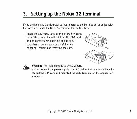
3. Setting up the Nokia 32 terminal
If you use Nokia 32 Configurator software, refer to the instructions supplied with the software. To use the Nokia 32 terminal for the first time:
1 Insert the SIM card. Keep all miniature SIM cards out of the reach of small children. The SIM card and its contacts can easily be damaged by scratches or bending, so be careful when handling, inserting or removing the card.
Warning! To avoid damage to the SIM card, do not connect the power supply to an AC wall outlet before you have in-stalled the SIM card and mounted the GSM terminal on the application module.
Eppu_en1.fm Page 11 Thursday, January 8, 2004 3:48 PM

Copyright © 2003 Nokia. All rights reserved. 12
2 Mount the GSM terminal on the application module using the two screws supplied with the terminal.
Note: If you mount the Nokia 32 terminal for example on a wall, attach the application module first to the wall with the two screws supplied with the terminal. Then mount the GSM terminal onto the application module.
3Connect a DTMF telephone to the trunk connector. For information on connecting the Nokia 32 terminal to the PBX (Private Branch Exchange), see “PBX installation” on page 14.
Warning! To avoid damaging the devices, you must connect the telephone to the trunk connector with a standard 6/6-pin RJ-11 connector that has only its two middle pins connected.
Note: The distance between the telephone or a PBX and the Nokia 32 terminal should not be less than 1 meter. The distance from one Nokia 32 terminal to another should be greater than 30 cm. In case of interference, try increasing the distance.
Eppu_en1.fm Page 12 Thursday, January 8, 2004 3:48 PM

Sett
ing
up t
he N
okia
32
term
inal
13Copyright © 2003 Nokia. All rights reserved.
4 Connect the power cord from the power supply to the Nokia 32 terminal.
5 Connect the power supply to an AC wall outlet. When the Nokia 32 terminal is powered up, it shows the GSM signal strength with light indicators. Make sure that the signal strength is adequate to make and receive calls, see “Light indicators” on page 25.
Note: Use only the ACW-5 power supply provided with the Nokia 32 terminal. The use of any other power supply may cause damage to the terminal.
6 Use the telephone connected to the Nokia 32 terminal to enter the PIN code, if your SIM card requires it: when light indicator 2 blinks red, lift the receiver. When you hear the enter PIN code tone, enter the PIN code followed by #. The Nokia 32 terminal gives the OK tone, and light indicator 1 lights up.
Note: If entering the PIN code fails, see “Entering PIN code does not succeed” on page 39. If the AutoPIN feature is active, the Nokia 32 terminal automatically enters your PIN code the next time the power is switched on.
7 Make a test call using the telephone connected to the Nokia 32 terminal.
To adjust the volume, key in 0**x during the call. Replace x with a value ranging from 1 (the lowest volume level) to 10 (the highest volume level).
Eppu_en1.fm Page 13 Thursday, January 8, 2004 3:48 PM
Copyright © 2003 Nokia. All rights reserved. 14
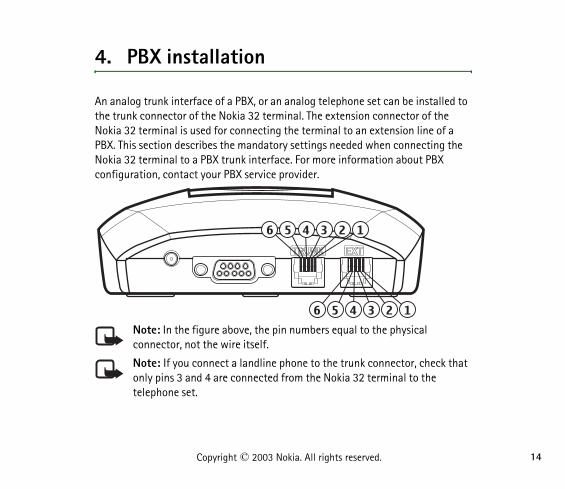
4. PBX installation
An analog trunk interface of a PBX, or an analog telephone set can be installed to the trunk connector of the Nokia 32 terminal. The extension connector of the Nokia 32 terminal is used for connecting the terminal to an extension line of a PBX. This section describes the mandatory settings needed when connecting the Nokia 32 terminal to a PBX trunk interface. For more information about PBX configuration, contact your PBX service provider.
Note: In the figure above, the pin numbers equal to the physical connector, not the wire itself.
Note: If you connect a landline phone to the trunk connector, check that only pins 3 and 4 are connected from the Nokia 32 terminal to the telephone set.
Eppu_en1.fm Page 14 Thursday, January 8, 2004 3:48 PM

PBX
inst
alla
tion
15Copyright © 2003 Nokia. All rights reserved.
■ Connecting the Nokia 32 terminal to a PBX trunk lineThe pins number 3 and 4 are TIP and RING. The leftmost pin in the connector is the ground connector. Connect pin 1 to the ground if the mains voltage might be a source of interference.
1 Disconnect the power supply of the Nokia 32 terminal from the AC wall outlet.
2 Connect the Nokia 32 terminal to the PBX trunk line using an RJ-11 cable.
3 Connect the power supply to the Nokia 32 terminal.
When light indicator 1 lights up, the network connection is established. When light indicator 2 lights up, the PBX trunk line connection is established.
If the AutoPIN feature is active, the Nokia 32 terminal attempts to connect to the network within 20-30 seconds. If the AutoPIN feature is not active, light indicator 2 starts to blink and you must enter your PIN code before the network connection can be established.
Eppu_en1.fm Page 15 Thursday, January 8, 2004 3:48 PM
Copyright © 2003 Nokia. All rights reserved. 16
Warning! Inappropriate installation of the Nokia 32 terminal to a PBX may damage the PBX or the Nokia 32 terminal. If an extension line of the PBX is connected to the trunk connector of the Nokia 32 terminal, the devices attempt to feed current to each other and they can be damaged.
To avoid damaging the devices, you must connect an analog trunk line of the PBX to the trunk connector of the Nokia 32 terminal with a standard 6/6-pin RJ-11 cable that has only its two middle pins connected. An analog extension line of the PBX must be connected to the extension connector of the Nokia 32 terminal with a standard 6/6-pin RJ-11 cable that has only its two middle pins connected. Note that the trunk and extension connectors of the Nokia 32 terminal cannot be used at the same time to connect a device.
Do not connect the Nokia 32 terminal to a digital (ISDN) interface of a PBX.
Making an incoming test callMake a call to the GSM number of the SIM card inserted into the Nokia 32 terminal. The Nokia 32 terminal routes the call to the switching centre and sends a ringing tone to the PBX trunk line. The switching centre then answers and routes the call.
Making an outgoing test callThe PBX must be configured to route certain outgoing numbers (for example numbers with a mobile prefix) to the trunk line to which the Nokia 32 terminal is
Eppu_en1.fm Page 16 Thursday, January 8, 2004 3:48 PM

PBX
inst
alla
tion
17Copyright © 2003 Nokia. All rights reserved.
connected before an outgoing call can be made. When the PBX sends a number to the Nokia 32 terminal, the Nokia 32 terminal connects the call.
■ Connecting the Nokia 32 terminal to a PBX extension line
Note: Only an analog extension interface can be connected to the extension connector.
Only pins 3 and 4 are used as A and B.
In the figure on page 14, the pin numbers correspond to the physical connector, not the wire itself.
The line impedance of the Nokia 32 terminal is 600 Ù and the maximum line current is 120 mA.
1 Disconnect the power supply of the Nokia 32 terminal from the AC wall outlet.
2 Connect the Nokia 32 terminal to the PBX extension line using an RJ-11 cable.
3 Connect the power supply to the Nokia 32 terminal.
If the AutoPIN feature is active, the Nokia 32 terminal attempts to connect to the network within 20-30 seconds. If the AutoPIN feature is not active, light indicator 2 starts to blink and you must enter your PIN code before the network connection can be established.
When light indicator 2 lights up, the network connection is established. When light indicator 3 lights up, the PBX extension connection is established.
Eppu_en1.fm Page 17 Thursday, January 8, 2004 3:48 PM

Copyright © 2003 Nokia. All rights reserved. 18
Note: When the Nokia 32 terminal is connected to an extension line of a PBX, some precautions must be taken. If no calling restrictions have been set up, any caller calling the GSM number of the Nokia 32 terminal gains access to the outgoing PBX trunk line and can make phone calls that are charged to the PBX owner.
To prevent this situation, configure the PBX to deny any outgoing calls coming from the extension line to which the Nokia 32 terminal is connected. If the PBX cannot be configured in such a way, it is possible to configure the Nokia 32 terminal automatically to call a predefined extension number when it receives a GSM call.
Note: When calls are restricted or barred, calls may be possible to the emergency number programmed into your phone (e.g. 112 or other official emergency number).
For further information about PBX configuration, see your PBX user’s guide.
Call monitoringThe PBX notifies the Nokia 32 terminal that the call is disconnected by providing either a busy tone or a silence to the Nokia 32 terminal. To clear the call to the GSM network, the Nokia 32 terminal must be set to monitor either one of those. The default setting is monitoring the busy tone.
Eppu_en1.fm Page 18 Thursday, January 8, 2004 3:48 PM

PBX
inst
alla
tion
19Copyright © 2003 Nokia. All rights reserved.
Setting up the busy tone monitoringWhen the Nokia 32 terminal is used in the extension mode with a PBX, the busy tone must be monitored on the PBX. Tone monitoring is needed because the PBX emits the tone when the hook-on transition occurs in the extension line.
The Tone Teaching feature of the Nokia 32 terminal is used to teach the Nokia 32 terminal the busy tone of each PBX.
After the Nokia 32 terminal has physically been installed to the final position, the learning mode can be activated:
1 Make a call from another extension to the extension where the Nokia 32 terminal is installed.
2 After you get the dial tone from the Nokia 32 terminal, dial **####**1234#88**own_ext_number# (own_ext_number is the extension number where you are commanding the Nokia 32 terminal from).
3 After the last digit (#), put the receiver down, and wait until the Nokia 32 terminal calls you back.
4 When the phone in the extension rings, pick up the receiver, and listen to the tone:
• If you hear a busy tone, the learning did not succeed, and you should repeat the steps.
• If you hear three beeps, the Nokia 32 terminal has learned the busy tone.
Eppu_en1.fm Page 19 Thursday, January 8, 2004 3:48 PM

Copyright © 2003 Nokia. All rights reserved. 20
Set the hook on, and wait for 60 seconds. The Nokia 32 terminal will reboot itself and is then ready for use.
Making an incoming test callMake a call to the GSM number of the SIM card inserted into the Nokia 32 terminal. The Nokia 32 terminal answers the call and opens the line to the PBX. The PBX then emits a dial tone and you can dial an extension number or outgoing number. After that, the PBX connects the call.
Making an outgoing test callMake a call to the PBX extension number to which the Nokia 32 terminal is connected. The Nokia 32 terminal answers the call. After that, you hear a dial tone, provided that the Nokia 32 terminal has been set to emit a dial tone, and you can dial the desired number. The Nokia 32 terminal connects the call.
The PBX can also be configured to route certain numbers automatically.
Functionality in extension mode
Outgoing call on the extension line, mode A
1 Key in the number of the extension to which the Nokia 32 terminal is connected.
2 The Nokia 32 terminal answers the call and emits a dial tone.
3 Key in the recipient’s number. The Nokia 32 terminal establishes the call.
Eppu_en1.fm Page 20 Thursday, January 8, 2004 3:48 PM

PBX
inst
alla
tion
21Copyright © 2003 Nokia. All rights reserved.
Outgoing call on the extension line, mode B
1 Key in the number of the extension where the Nokia 32 terminal is connected.
2 The Nokia 32 terminal answers the call and provides silence.
3 Key in the recipient’s number. The Nokia 32 terminal establishes the call.
Incoming call on the extension line, mode A
1 The Nokia 32 terminal answers the call and opens the extension line.
2 The PBX emits a dial tone.
3 Enter an extension number or outgoing number.
4 The PBX routes the call as if the call would come from an extension telephone.
Incoming call on the extension line, mode B
1 The Nokia 32 terminal answers the incoming call and opens the extension line.
2 The Nokia 32 terminal sends a predefined number to the PBX extension.
3 The recipient answers the call.
Eppu_en1.fm Page 21 Thursday, January 8, 2004 3:48 PM

Copyright © 2003 Nokia. All rights reserved. 22
5. Connecting the Nokia 32 terminal to a fax machine
The Nokia 32 terminal supports connection to Group 3 analog fax machines. The fax machine is connected to the RJ11 trunk connector of the Nokia 32 terminal with a 2-wire connection.
Note: The fax functionality must be activated on your SIM card before you can send or receive faxes.
Eppu_en1.fm Page 22 Thursday, January 8, 2004 3:48 PM

Conn
ectin
g th
e N
okia
32
term
inal
to
a fa
x m
achi
ne
23Copyright © 2003 Nokia. All rights reserved.
■ Sending faxes
1 Connect the analog fax machine to the Nokia 32 terminal.
2 Dial *01* to inform the Nokia 32 terminal about the fax call.
3 Dial the recipient’s number.
Example: *01*recipient’s number
■ Receiving faxesIncoming faxes are received in the same way as using a fixed line.
Note: SIM cards usually have a separate number for fax usage. For incoming faxes, the fax number of the SIM card is used. For information on using fax services, contact your service provider.
If the Nokia 32 terminal does not receive information about the incoming call type from the GSM network, dial *01#* to force the Nokia 32 terminal to receive the next incoming call as a fax call. This temporary setting is deactivated by receiving a fax or by dialling #01#*.
For the light indicators when waiting for a fax call, see “Light indicators” on page 25.
■ ConfigurationIn the Fax connection menu of Nokia 32 Configurator software, you can select to route incoming fax calls to an analog fax (RJ-11 trunk port, default) or a PC fax (RS232 port).
Eppu_en1.fm Page 23 Thursday, January 8, 2004 3:48 PM

Copyright © 2003 Nokia. All rights reserved. 24
To force the Nokia 32 terminal to handle all calls as analog fax calls, select the Permanent fax mode in Nokia 32 Configurator. To disable the Permanent fax mode, select either PC fax or Analog fax mode.
In the Permanent fax mode, it is not necessary to use the *01* prefix when sending an analog fax.
To make the configurations with a landline telephone, dial:
• **####**1234#12**0# for Analog fax mode (default)
• **####**1234#12**1# for PC fax mode
• **####**1234#12**2# for Permanent analog fax mode (only fax calls available)
After the command, key in 555**# to save the new settings and restart the terminal.
Note: **####**1234# activates the Configuration mode of the Nokia 32 terminal.
When you have given the commands successfully to the terminal with the landline telephone, you hear the OK tone in the receiver.
For the light indicators in the Permanent fax mode, see “Light indicators” on page 25.
Eppu_en1.fm Page 24 Thursday, January 8, 2004 3:48 PM
Ligh
t in
dica
tors
25Copyright © 2003 Nokia. All rights reserved.
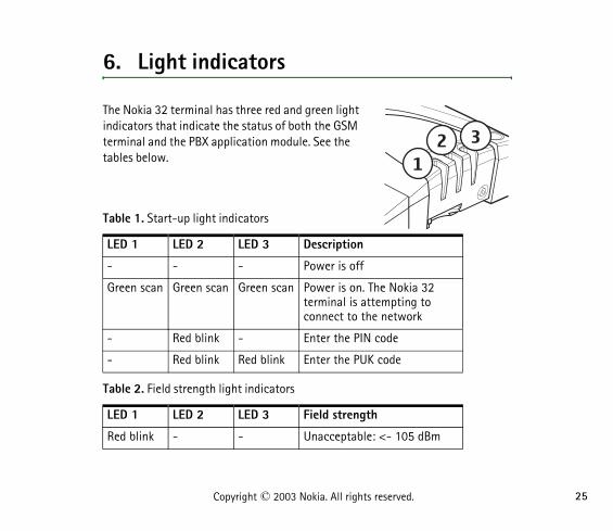
6. Light indicators
The Nokia 32 terminal has three red and green light indicators that indicate the status of both the GSM terminal and the PBX application module. See the tables below.
Table 1. Start-up light indicators
Table 2. Field strength light indicators
LED 1 LED 2 LED 3 Description
- - - Power is off
Green scan Green scan Green scan Power is on. The Nokia 32 terminal is attempting to connect to the network
- Red blink - Enter the PIN code
- Red blink Red blink Enter the PUK code
LED 1 LED 2 LED 3 Field strength
Red blink - - Unacceptable: <- 105 dBm
Eppu_en1.fm Page 25 Thursday, January 8, 2004 3:48 PM

Copyright © 2003 Nokia. All rights reserved. 26
Table 3. Light indicators during normal operation
* Depends on whether the Nokia 32 terminal is in the trunk or the extension mode.
Green blink - - Unacceptable: 105...100 dBm
Green - - Weak: 100...95 dBm
Green Green blink - Weak: 95...90 dBm
Green Green - Moderate: 90...85 dBm
Green Green Green blink Moderate: 85...80 dBm
Green Green Green Good: -> 80 dBm
LED 1 LED 2 LED 3 Description
- Green Green In service, trunk mode
Green - Green In service, extension mode
* * Green blink Call in progress/incoming call
* * Green/red blink
Message/voice mail received
* * Red blink Message storage full
- Green blink Green In Permanent fax mode/waiting for a fax call
LED 1 LED 2 LED 3 Field strength
Eppu_en1.fm Page 26 Thursday, January 8, 2004 3:48 PM
Ligh
t in
dica
tors
27Copyright © 2003 Nokia. All rights reserved.
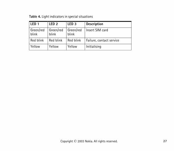
Table 4. Light indicators in special situations
LED 1 LED 2 LED 3 Description
Green/red blink
Green/red blink
Green/red blink
Insert SIM card
Red blink Red blink Red blink Failure, contact service
Yellow Yellow Yellow Initialising
Eppu_en1.fm Page 27 Thursday, January 8, 2004 3:48 PM

Copyright © 2003 Nokia. All rights reserved. 28
7. Tone indicators
The following tones indicate the state of the Nokia 32 terminal when a telephone is used to change the settings of the Nokia 32 terminal or to check whether the Nokia 32 terminal has received new SMS messages.
Tones Description
- - - - - - - - - - - - - - - - - Enter SIM card
- _ _ - _ _ - _ _ Enter PIN code
- - Enter PUK code
- - - - Error
OK
SMS received
Eppu_en1.fm Page 28 Thursday, January 8, 2004 3:48 PM

Conf
igur
atio
n
29Copyright © 2003 Nokia. All rights reserved.
8. Configuration
The Nokia 32 terminal can be configured using a DTMF telephone connected to the application module, or using Nokia 32 Configurator software. Nokia 32 Configurator is a special tool for the configuration of the terminal. Detailed instructions about using Nokia 32 Configurator is supplied with the software.
Most of the Nokia 32 terminal settings can be configured with a normal DTMF telephone.
■ Basic settingsThe basic settings include PIN and PUK code input, speaker volume control, and activation of the Intensity of Field (IOF) feature.
Entering PIN and PUK codeTo enter the PIN code, key in PINCode#.
To enter the PUK code, key in PUKCode#.
If entering the PIN code fails three times, the code is blocked. You can unblock it by entering your PUK (PIN Unblocking Key) code. After entering the PUK code, you must assign a new PIN code to the SIM card.
Enter a new PIN code (4-8 digits) followed by # when light indicator 2 blinks and the 'enter PIN code' tone is heard. Confirm the new PIN code by re-entering the code followed by #.
Eppu_en1.fm Page 29 Thursday, January 8, 2004 3:48 PM

Copyright © 2003 Nokia. All rights reserved. 30
Adjusting telephone speaker volumeTo adjust the telephone set's speaker volume, key in 0**x during the call. Replace x with a value between 1 (the lowest volume level) and 10 (the highest volume level). The default value is 5.
Activating IOFIoF (Intensity of Field strength) is activated when the terminal is powered up. The field strength is shown with the terminal LEDs for ten seconds, after which the feature is automatically deactivated.
■ Advanced settingsTo change the advanced settings, you need to activate the configuration mode of the Nokia 32 terminal.
1 Key in **####**.
2 The terminal prompts for an access code. The default code is 1234. You can change the code with Nokia 32 Configurator. To enter the access code, key in AccessCode#.
3 Configure the settings with a normal DTMF telephone. The table below lists the available settings.
Eppu_en1.fm Page 30 Thursday, January 8, 2004 3:48 PM

Conf
igur
atio
n
31Copyright © 2003 Nokia. All rights reserved.
4 Key in 555**# to save the new settings and to restart the terminal.
Feature Command to change settings
Note
Loop interruption time [ms]
2**Interruption_Time# The default loop interruption time is 300 ms
Polarity reversal time [ms]
3**Polarity_Reversal_Time#
Calling line identification (CLI) mode
4**CLI_Mode# The available modes are:000 = ETSI FSK001 = DTMF010 = DTMF-DK
Network selection 5**Operator_Code# For automatic network selection, enter 000 as the Operator Code
Extension mode, outgoing call
6**#7**#
Mode A (default)Mode B
Extension mode, incoming call
8**#9**Pre-Defined_Extension_Number#
Mode A (default)Mode B
Eppu_en1.fm Page 31 Thursday, January 8, 2004 3:48 PM

Copyright © 2003 Nokia. All rights reserved. 32
9. Features
■ Supplementary servicesThese features are network services provided by wireless network service providers. These services differ from one network and country to another. For details, check with the local network service provider. The Nokia 32 terminal supports the GSM Phase 2+ Supplementary Services:
• Number identification
• Call forwarding
• Call waiting
• In-call handling
• Call transfer
• Call restriction
• High Speed Circuit Switched Data (HSCSD)
• General Packet Radio Service (GPRS)
• Security options
SMS (Short Message Service)The Nokia 32 terminal supports both Mobile Originated (MO) and Mobile Terminated (MT) short message services with the help of AT commands. A PC and an RS-232 data cable are needed when using the SMS feature.
Eppu_en1.fm Page 32 Thursday, January 8, 2004 3:48 PM

Feat
ures
33Copyright © 2003 Nokia. All rights reserved.
The Nokia 32 terminal indicates the received SMS with light indicators and also by emitting a tone in the telephone set's receiver.
Voice mailThe Nokia 32 terminal supports the GSM network voice mail service. If the network sends an SMS of received voice mail, the Nokia 32 terminal indicates the received SMS with light indicators and also by emitting a tone in the telephone set's receiver.
High Speed Circuit Switched DataThe GSM terminal supports High Speed Circuit Switched Data (HSCSD) that enables a data transmission speed of up to 43.2 kbps. HSCSD relies on the simultaneous use of multiple GSM timeslots. HSCSD is a network service. For details, contact your service provider.
General Packet Radio ServiceThe General Packet Radio Service (GPRS) utilises packet switched technology where information is transmitted in small bursts of data. The GPRS mobile station class of the Nokia 32 terminal is class B. This means that both GPRS connections and circuit switched connections are possible, although it must be defined which one is used each time. The Nokia 32 terminal supports GPRS multi-slot class 6, thus multiple timeslots can be used for data transfer at the same time: 3+1, 2+2 or 2+1 slots.
Eppu_en1.fm Page 33 Thursday, January 8, 2004 3:48 PM

Copyright © 2003 Nokia. All rights reserved. 34
Calling Line IdentificationThe Calling Line Identification (CLI) feature displays the caller's number with an external calling line display device. Two signalling methods are available: ETSI FSK (European Telecommunications Standards Institute Frequency Shift Keying) and DTMF (Dual Tone Multi Frequency). The signalling mode varies depending on the operator and the country. The default mode is ETSI FSK.
Note: Nokia does not provide CLI devices. For details and availability, contact your service provider.
Charge Advice InformationThe Charge Advice Information (CAI) feature indicates the cost of the most recent calls and the total of calls in an external tariff pulse counter or display. The Nokia 32 terminal converts GSM's standard Advice of Charge (AoC) information to Charge Advice Information (CAI) tariff pulse (12/16 kHz) information, in which case an external tariff counter or display can be used. The CAI settings of the Nokia 32 terminal can be modified using Nokia 32 Configurator software.
Note: Data call costs cannot be shown on the display or counter. Nokia does not provide CAI devices. For details and availability, contact your service provider.
Automatic Area Code and routingThe Automatic Area Code (AAC) feature allows you for example to dial local numbers without a local area code in the GSM network. Before the number is sent, the Nokia 32 terminal adds a pre-programmed local area code automatically. You
Eppu_en1.fm Page 34 Thursday, January 8, 2004 3:48 PM

Feat
ures
35Copyright © 2003 Nokia. All rights reserved.
can also specify the Nokia 32 terminal to change certain prefixes automatically, for example to provide a cost-effective route. The AAC and routing settings can be modified using Nokia 32 Configurator software.
Intensity of FieldThe intensity of Field (IoF) feature indicates the strength of the received radio signal. IoF (Intensity of Field strength) is activated when the terminal is powered up. The field strength is shown with the terminal LEDs for ten seconds, after which the feature is automatically deactivated.
Faster call setupFaster call setup allows faster call establishment. The last 10 different dialled numbers are stored in the memory of the Nokia 32 terminal. If the dialled number matches one of the stored numbers, there is no delay before the Nokia 32 terminal sends the number, and the call is established immediately.
AutoPIN security featureThe Nokia 32 terminal supports the AutoPIN security feature. The PIN code is saved in the memory of the Nokia 32 terminal when the code is entered for the first time or when the code is changed. In addition, the AutoPIN feature enables device recovery after occasional power cuts without on-site intervention. The Nokia 32 terminal enters the PIN code automatically the next time it is switched on.
Eppu_en1.fm Page 35 Thursday, January 8, 2004 3:48 PM

Copyright © 2003 Nokia. All rights reserved. 36
Use of the SIM card in other GSM terminals or mobile phones can be prevented. The user does not have to know the PIN code. However, other SIM cards can be used with the Nokia 32 terminal. The AutoPIN feature can be deactivated using Nokia 32 Configurator software. The default is that the AutoPIN feature is active.
Eppu_en1.fm Page 36 Thursday, January 8, 2004 3:48 PM

Nok
ia 3
2 te
rmin
al’s
acce
ssor
ies
37Copyright © 2003 Nokia. All rights reserved.
10. Nokia 32 terminal’s accessories
For availability of approved accessories, please check with your dealer.
• Power supply (ACW-5): supplied with the Nokia 32 terminal. Check the model number of any charger before use with this device. This device is intended for use when supplied with power from ACW-5.
• Backup battery set: features a backup battery (BBW-6) and power supply (ACW-4).
• Data package: features an RS-232 data cable and an AT command guide.
• Antenna adapter (XRM-1): allows an external antenna to be connected to the Nokia 32 terminal.
• Configurator software package: for more advanced configuration of the Nokia 32 terminal. Features the software and a configurator cable.
Warning! Use only batteries, chargers and accessories approved by the terminal manufacturer for use with this particular terminal model. The use of any other types may invalidate any approval or warranty applying to the terminal, and may be dangerous.
When you disconnect the power cord of any accessory, grasp and pull the plug, not the cord.
Eppu_en1.fm Page 37 Thursday, January 8, 2004 3:48 PM

Copyright © 2003 Nokia. All rights reserved. 38
11. Troubleshooting
For more information on troubleshooting, please see FAQ (Frequently Asked Questions) at www.nokia.com.
■ First things to check1 If a telephone is connected to the Nokia 32 terminal, check that it is connected
to the trunk connector and that the connection is firm.
2 Check that the power supply is firmly connected to the Nokia 32 terminal and to an AC outlet.
3 Check that the antenna is firmly connected to the Nokia 32 terminal.
■ Dial tone is not heardIf the dial tone is not heard when you lift the receiver of the telephone connected to the Nokia 32 terminal:
1 Check that the power supply is firmly connected to the Nokia 32 terminal and to the AC wall outlet.
2 Check the light indicators for further information.
3 If the dial tone is still not heard, disconnect the power supply from the AC wall outlet and then reconnect it.
Eppu_en1.fm Page 38 Thursday, January 8, 2004 3:48 PM

Trou
bles
hoot
ing
39Copyright © 2003 Nokia. All rights reserved.
■ Noise is heard during a callThe Nokia 32 terminal may be too close to a telephone or another electronic device. Place the Nokia 32 terminal and the devices possibly interfering with the Nokia 32 terminal further apart from each other.
■ Reception is poorIf there are problems with reception, for example interruptions in speech, the signal may be too weak. Check the signal strength. If the signal is weaker than 95 dBm, move the Nokia 32 terminal to another location. If the Nokia 32 terminal does not receive a stronger signal, contact your service provider.
■ Entering PIN code does not succeedIf entering the PIN code fails three times, the code is blocked. You can unblock it by entering your PUK (PIN Unblocking Key) code. The PUK code may be supplied with the SIM card. If not, contact your local service provider for the code. If you lose the code, contact your service provider. When the PIN code is blocked, light indicators 2 and 3 blink. To unblock the code:
1 Lift the receiver of the telephone connected to the Nokia 32 terminal. When the enter PUK code tone is heard, enter your PUK code followed by #.
2 When light indicator 2 blinks and you hear the enter PIN code tone, enter a new PIN code (4 - 8 digits) followed by #.
3 Confirm the new PIN code by re-entering the code followed by #.
Eppu_en1.fm Page 39 Thursday, January 8, 2004 3:48 PM

Copyright © 2003 Nokia. All rights reserved. 40
■ Nokia 32 terminal cannot be reached in extension mode
Check that light indicator 2 is lit. Check also that the extension line is connected to the extension connector. Restart the Nokia 32 terminal and make sure that before powering up the Nokia 32 terminal, it is properly connected to the extension line.
Eppu_en1.fm Page 40 Thursday, January 8, 2004 3:48 PM

Tech
nica
l spe
cific
atio
ns
41Copyright © 2003 Nokia. All rights reserved.
12. Technical specifications
Technical data
Telephone/PBX trunk interface
Size 121 x 158 x 45 mm
Weight 239 g
Operating temperature -10ºC...+55ºC
Storage temperature -40ºC...+85ºC
Humidity range, operation 20-75%
Humidity range, storage 5-95%
Input voltage Absolute min. 6.2 V, absolute max. 14.0 V
Small size SIM cards supported
RF Power 2W/1W (900/1800 Mhz)
Line voltage high impedance mode
50 V
Line impedance 600 Ohm
Fax connection speed Up to 9600 bps
Eppu_en1.fm Page 41 Thursday, January 8, 2004 3:48 PM

Copyright © 2003 Nokia. All rights reserved. 42
Extension interface
Power supply ACW-5
AntennaThe Nokia 32 terminal has an integrated antenna. The use of an external antenna is supported with the XRM-1 antenna adapter.
RS-232A D9 female connector for standard level RS-232 is available. It supports AT commands (ITU-T V. 25ter, ETS GSM 07.07, ETS GSM 07.05).
Electromagnetic compatibility (Europe)The GSM terminal is tested for electromagnetic compatibility (EMC) according to the ETS 300 342-1/13/standards. The application module fullfils the ITU-T
Off-hook AC impedance 600 Ohm
Loop DC current 15-120 mA
Voltage 13.5 V
DC current 750 mA
Operating range 90-264 Vac
Frequency range 47-63 Hz
Weight 70 g + cables
Volume <110 cm3
Eppu_en1.fm Page 42 Thursday, January 8, 2004 3:48 PM

Tech
nica
l spe
cific
atio
ns
43Copyright © 2003 Nokia. All rights reserved.
standard and the ETS 300-001 specifications for PBX extension and trunk connections. The module supports also ETS 300-659 Calling Line Identification (FSK and DTMF).
Eppu_en1.fm Page 43 Thursday, January 8, 2004 3:48 PM
Copyright © 2003 Nokia. All rights reserved. 44
13. Care and maintenance
Your terminal is a product of superior design and craftsmanship and should be treated with care. The suggestions below will help you to fulfil any warranty obligations and to enjoy this product for many years.
• Keep the terminal and all its parts and accessories out of the reach of small children.
• Keep the terminal dry. Precipitation, humidity and all types of liquids or moisture can contain minerals that will corrode electronic circuits.
• Do not use or store the terminal in dusty, dirty areas. Its moving parts can be damaged.
• Do not store the terminal in hot areas. High temperatures can shorten the life of electronic devices, damage batteries, and warp or melt certain plastics.
• Do not store the terminal in cold areas. When it warms up (to its normal temperature), moisture can form inside, which may damage electronic circuit boards.
• Do not attempt to open the terminal. Non-expert handling may damage it.
• Do not drop, knock or shake the terminal. Rough handling can break internal circuit boards.
• Do not use harsh chemicals, cleaning solvents, or strong detergents to clean the terminal.
• Do not paint the terminal. Paint can clog the moving parts and prevent proper operation.
• Unauthorised antennas, modifications or attachments could damage the terminal and may violate regulations governing radio devices.
Eppu_en1.fm Page 44 Thursday, January 8, 2004 3:48 PM
Care
and
mai
nten
ance
45Copyright © 2003 Nokia. All rights reserved.
All of the above suggestions apply equally to your terminal, battery, charger or any accessory. If any of them is not working properly, take it to your nearest qualified service facility. The personnel there will assist you and, if necessary, arrange for service.
Eppu_en1.fm Page 45 Thursday, January 8, 2004 3:48 PM
Copyright © 2003 Nokia. All rights reserved. 46
14. Important safety information
Operating environmentRemember to follow any special regulations in force in any area and do not install your terminal where its usage is forbidden, or where it may cause interference or danger. Use the terminal only in its normal operating position.
Electronic devicesMost modern electronic equipment is shielded from radio frequency (RF) signals. However, certain electronic equipment may not be shielded against the RF signals from your terminal.
Medical devicesOperation of any radio transmitting equipment, including cellular terminals, may interfere with the functionality of inadequately protected medical devices. Consult a physician or the manufacturer of the medical device to determine if they are adequately shielded from external RF energy or if you have any questions. Do not install your terminal in health care facilities where any regulations prohibit using cellular terminals. Hospitals or health care facilities may be using equipment that could be sensitive to external RF energy.
Posted facilitiesDo not install your terminal in any facility where posted notices prohibit it.
Eppu_en1.fm Page 46 Thursday, January 8, 2004 3:48 PM

Impo
rtan
t sa
fety
info
rmat
ion
47Copyright © 2003 Nokia. All rights reserved.
Potentially explosive atmospheresDo not install your terminal in any area with a potentially explosive atmosphere and obey all signs and instructions. Sparks in such areas could cause an explosion or fire resulting in bodily injury or even death. Users are reminded of the need to observe restrictions on the use of radio equipment in fuel depots (fuel storage and distribution areas), chemical plants or where blasting operations are in progress. Areas with a potentially explosive atmosphere are often but not always clearly marked. They include below deck on boats; chemical transfer or storage facilities; vehicles using liquified petroleum gas (such as propane or butane); areas where the air contains chemicals or particles, such as grain, dust or metal powders; and any other area where you would normally be advised to turn off your vehicle engine.
Emergency callsThis terminal operates using radio signals, wireless and landline networks as well as user-programmed functions. Because of this, connections in all conditions cannot be guaranteed. Therefore you should never rely solely upon any wireless terminal for essential communications (e.g. medical emergencies).
Emergency calls may not be possible on all wireless phone networks or when certain network services and/or terminal features are in use. Check with local service providers.
To make an emergency call:
1. If the terminal is not on, power it up. Check for adequate signal strength.
2. If a call is on, put down the handset to exit the call.
3. Wait for the dial tone and enter the emergency number.
Eppu_en1.fm Page 47 Thursday, January 8, 2004 3:48 PM

Copyright © 2003 Nokia. All rights reserved. 48
If certain features are in use, you may first need to turn those features off before you can make an emergency call. Consult this guide and your local cellular service provider.
When making an emergency call, remember to give all the necessary information as accurately as possible. Remember that your terminal may be the only means of communication at the scene of an accident - do not cut off the call until given permission to do so.
Eppu_en1.fm Page 48 Thursday, January 8, 2004 3:48 PM


![SAP HowTo Guide - Unlocking User SAPStar [User Guide]](https://static.documents.pub/doc/80x56/544ac849b1af9f7c4f8b4bd1/sap-howto-guide-unlocking-user-sapstar-user-guide.jpg)


