209
User Guide SMART SWITCH LGS3XX

1
User Guide
SMART SWITCH
LGS3XX
2
Contents
Chapter 1 – Getting Started ............................................................................... 5
Chapter 2 – System Status ................................................................................. 9
System Summary .................................................................................................................................... 9 RMON ........................................................................................................................................................ 10 Interface Statistics .............................................................................................................................. 17
Chapter 3 – Quick Start ..................................................................................... 19
Chapter 4 – System Management ................................................................. 20
System Information ............................................................................................................................. 20 Management Session Timeout ........................................................................................................ 21 Time ........................................................................................................................................................... 21 SNMP ........................................................................................................................................................ 27 Logs ........................................................................................................................................................... 44
Chapter 5 – Port Management ........................................................................ 50
Ports .......................................................................................................................................................... 50 Link Aggregation ................................................................................................................................... 52 Green Ethernet ...................................................................................................................................... 56 PoE ............................................................................................................................................................. 59 Discovery - LLDP .................................................................................................................................. 65
Chapter 6 – VLAN Management ..................................................................... 77
VLANs ....................................................................................................................................................... 77 Interfaces ................................................................................................................................................ 81 VLAN Memberships ............................................................................................................................. 84 VLAN Groups.......................................................................................................................................... 85 Voice VLAN ............................................................................................................................................. 88
Chapter 7 - Spanning Tree Management .................................................... 93
Spanning Tree ........................................................................................................................................ 94 STP Interfaces ....................................................................................................................................... 96 RSTP Interfaces .................................................................................................................................... 97

3
MSTP Properties ................................................................................................................................... 99 MSTP Instance Status ..................................................................................................................... 102 MSTP Instance Interface ................................................................................................................ 103
Chapter 8 - MAC Address Management .................................................. 106
Dynamic MAC Addresses ............................................................................................................... 106 Static MAC Addresses .................................................................................................................... 107 Reserved MAC Addresses ............................................................................................................. 108
Chapter 9 – Multicast ...................................................................................... 110
Feature Configuration ..................................................................................................................... 112 IGMP Snooping ................................................................................................................................... 114 MLD Snooping .................................................................................................................................... 115 Multicast Router Ports .................................................................................................................... 116 Forward All ........................................................................................................................................... 117 Unregistered Multicast ................................................................................................................... 118 IGMP/MLD IP Group Addresses ................................................................................................... 120 MAC Group Address FDB ............................................................................................................... 121 IP Group Address FDB ..................................................................................................................... 123
Chapter 10 - IP Interface ............................................................................... 125
IPv4 ......................................................................................................................................................... 125 IPv6 ......................................................................................................................................................... 128
Chapter 11 - IP Network Operations .......................................................... 135
Domain Name System ...................................................................................................................... 135 DHCP ...................................................................................................................................................... 136 DHCP Snooping Binding Database ............................................................................................. 141 Interface Settings ............................................................................................................................. 143
Chapter 12 – Security ..................................................................................... 144
Management Security ..................................................................................................................... 144 RADIUS ................................................................................................................................................. 152 Network Access Control ................................................................................................................. 155 Port Security ....................................................................................................................................... 165 Storm Control ..................................................................................................................................... 167

4
Chapter 13 - Access Control List ............................................................... 169
MAC-Based ACL ................................................................................................................................ 170 MAC-Based ACE ................................................................................................................................ 171 IPv4-Based ACL ................................................................................................................................. 173 IPv4-Based ACE................................................................................................................................. 174 IPv6-Based ACL ................................................................................................................................. 176 IPv6-Based ACE................................................................................................................................. 176 ACL Binding ......................................................................................................................................... 178
Chapter 14 - Quality of Service ................................................................... 180
Feature Configuration ..................................................................................................................... 182 Queue Scheduling ............................................................................................................................. 183 CoS/802.1p to Queue ..................................................................................................................... 184 DSCP to Queue ................................................................................................................................... 186 Bandwidth Control ............................................................................................................................ 187 Egress Shaping .................................................................................................................................. 188 Basic QoS ............................................................................................................................................. 189 QoS Statistics .................................................................................................................................... 191
Chapter 15 - Maintenance ............................................................................ 193
Reboot ................................................................................................................................................... 193 File Management ............................................................................................................................... 193 Diagnostics .......................................................................................................................................... 201
Chapter - 16 Support ...................................................................................... 208

5
Chapter 1 – Getting Started There are two ways to configure the device: through the graphical user interface and through the menu command line interface.
Starting the Web-based Configuration Utility
This section describes how to navigate the Web-based switch configuration utility. If you are using a pop-up blocker, make sure it is disabled. The following browsers are supported:
• Firefox (versions 16 and latest) • IE version (versions 10 and latest) • Chrome (versions 35 and latest)
Browser Restrictions
If you are using IPv6 interfaces on your management station, use the IPv6 global address and not the IPv6 link local address to access the device from your browser.
Launching the Configuration Utility
To open the Web-based configuration utility, do the following:
1. Open a Web browser.
2. Enter the IP address of the device you are configuring in the address bar on the browser, and then press Enter.
NOTE—When the device is using the factory default IP address of 192.168.1.251, its power LED flashes continuously. When the device is using a DHCP assigned IP address or an administrator-configured static IP address, the power LED is on solid.
3. On the login page, enter the username/password. The password can contain up to 64 ASCII characters. The default username is “admin” and the default password is “admin”.

6
Logging Out
By default, the application logs out after ten minutes of inactivity.
CAUTION Unless the Running Configuration is copied to the Startup Configuration, rebooting the device will remove all changes made since the last time the file was saved. Save the Running Configuration to the Startup Configuration before logging off to preserve any changes you made during this session.
When you click Quick Start > Save Your Configurations, the Configuration File Copy page appears. Save the Running Configuration file by copying it to the Startup Configuration file.
To log out, click Logout in the top right corner of any page. The system logs out of the device.
NOTE—When a timeout occurs or you intentionally log out of the system, a message appears, and the login page appears with a message indicating the logged-out state.
Interface Naming Conventions
Within the GUI, interfaces are denoted by linking the following elements:
• Type of interface: The following types of interfaces are found on the switch: o Gigabit Ethernet ports (displayed as GE). o LAG (Port Channel) (displayed as LAG). o VLAN
• Interface Number: Port, LAG or VLAN ID
Window Navigation
This section describes the features of the Web-based switch configuration utility.
Application Header
The Application Header appears on every page. It provides the following application links:
Application Link Name Description
Logout Click to log out of the Web-based switch configuration utility.
Firmware Version Display the device version number.
Help Click for the link to this administration guide.

7
Management Buttons
The following table describes the commonly used buttons that appear on various pages in the system.
Button Name Description
Add Click to display the related Add page and add an entry to a table. Enter the information and click Apply to save it to the Running Configuration. Click Close to return to the main page. Click Save to display the Configuration File Copy page and save the Running Configuration to the Startup Configuration file type on the device.
Apply Click to apply changes to the Running Configuration on the device. If the device is rebooted, the Running Configuration is lost unless it is saved to the Startup Configuration file type or another file type. Click Save to display the Configuration File Copy page and save the Running Configuration to the Startup Configuration file type on the device.
Close Click to return to the previous page. Any changes not applied are cleared.
Clear All Click to clear the statistic counters for all interfaces.
Clear Click to clear information, such a counters of an interface, all interface, or log files.
Delete After selecting an entry in the table, click Delete to remove.
Edit Select the entry and click Edit.
1. Click Apply to save the changes to the Running Configuration.
2. Click Close to return to the main page.
Search Enter the query filtering criteria and click Search.
Refresh Click Refresh to refresh the counter values.
Test or Start Click Test/Start to perform the related tests.
View or View All Click View to display details associated with the entry selected or for all entries (respectively).

8
Configuring with Menu Command Line Interface
To configure with the device through the menu CLI:
1. Log on to the device through telnet.
2. Configure the device.
3. Click Logout.

9
Chapter 2 – System Status
System Summary
The System Summary page provides a graphic view of the device, and displays device status, hardware information, firmware version information, general PoE status, and other items.
To view system information, click System Status > System Summary. The System Summary page contains system and hardware information.
• System Mode—Specifies whether the system is operating in Layer 2 system mode.
• System Description—A description of the system.
• System Location—Physical location of the device. To edit this field, go to Configuration > System Management > System Information.
• System Contact—Name of a contact person. To edit this field, go to Configuration > System Management > System Information.
• Host Name—Name of the device. By default, the device host name is composed of the word “switch” followed by the three least significant bytes of the device base MAC address (the six furthest right hexadecimal digits).
• Base MAC Address—Device MAC address.
• SNMP Object ID—Unique vendor identification of the network management subsystem.

10
• Firmware Version—Firmware version number.
• Boot Code Version—Boot version number.
• Hardware Version —Hardware version number of the device.
• Serial Number—Serial number. Device Status
• Fan Status—Applicable only to models that have fans. The following values are possible: o OK—Fan is operating normally. o Fail—Fan is not operating correctly.
• Date & Time—System date and time.
• System Uptime—Length of time since last reboot.
RMON RMON Statistics
The Statistics page displays detailed information regarding packet sizes and information regarding physical layer errors. The information displayed is according to the RMON (Remote Network Monitoring) standard. An oversized packet is defined as an ethernet frame with the following criteria:
• Packet length is greater than MRU byte size.
• Collision event has not been detected.
• Late collision event has not been detected.
• Received (Rx) error event has not been detected.
• Packet has a valid CRC.

11
To view RMON statistics and/or set the refresh rate:
1. Click System Status > RMON > Statistics.
2. Select the Interface for which statistics are to be displayed.
3. Select the Refresh Rate, the time period that passes before the interface statistics are refreshed.
The statistics are displayed for the selected interface.
• Bytes Received—Number of octets received, including bad packets and FCS octets, but excluding framing bits.
• Drop Events—Number of packets dropped.
• Packets Received—Number of good packets received, including Multicast and Broadcast packets.
• Broadcast Packets Received—Number of good Broadcast packets received. This number does not include Multicast packets.
• Multicast Packets Received—Number of good Multicast packets received.
• CRC & Align Errors—Number of CRC and Align errors that have occurred.
• Undersize Packets—Number of undersized packets (less than 64 octets) received.
• Oversize Packets—Number of oversized packets (over 2000 octets) received.
• Fragments—Number of fragments (packets with less than 64 octets, excluding framing bits, but including Frame Check Sequence octets) received.
• Jabbers—Total number received packets that were longer than 1632 octets. This number excludes frame bits, but includes FCS octets that had either a bad FCS with an integral number of octets (FCS Error) or a bad FCS with a non-integral octet (Alignment Error) number. A jabber packet is defined as an Ethernet frame that satisfies the following criteria:
• Packet data length is greater than MRU.
• Packet has an invalid CRC.
• Received (Rx) Error Event has not been detected.
• Collisions—Number of collisions received. If Jumbo Frames are enabled, the threshold of Jabber Frames is raised to the maximum size of Jumbo Frames.
• Frames of 64 Bytes—Number of frames, containing 64 bytes that were received.
• Frames of 65 to 127 Bytes—Number of frames, containing 65-127 bytes that were received.
• Frames of 128 to 255 Bytes—Number of frames, containing 128-255 bytes that were received.
• Frames of 256 to 511 Bytes—Number of frames, containing 256-511 bytes that were received.

12
• Frames of 512 to 1023 Bytes—Number of frames, containing 512-1023 bytes that were received.
• Packets of 1024 and More Bytes—Number of frames, containing 1024- 2000 bytes, and Jumbo Frames, that were received.
To clear or view statistics counters:
• Click Refresh to refresh the counters on the page.
• Click Clear to clear the selected interfaces counters.
• Click View All to see all ports on a single page.
RMON History
The RMON feature enables monitoring statistics per interface.
The History Control Table page defines the sampling frequency, amount of samples to store and the port from which to gather the data.
After the data is sampled and stored, it appears in the History Table page that can be viewed by clicking the History button.
To enter RMON control information:
1. Click System Status > RMON > History.
2. Click Add.
3. Enter the parameters.
• New History Control Entry Index—Displays the number of the new History table entry.
• Source Interface—Select the type of interface from which the history samples are to be taken.
• Maximum Samples—Enter the number of samples to store.
• Samples Collected—RMON is allowed by the standard to not grant all requested samples, but rather to limit the number of samples per request. Therefore, this field represents the sample number actually granted to the request that is equal or less than the requested maximum sample.
• Sampling Interval—Enter the time in seconds that samples are collected from the ports. The field range is 1-3600.
• Owner—Enter the RMON station or user that requested the RMON information.
13
4. Click Apply. The entry is added to the History Control Table page, and the Running Configuration file is updated.
5. Click the History button (described below) to view the actual statistics.
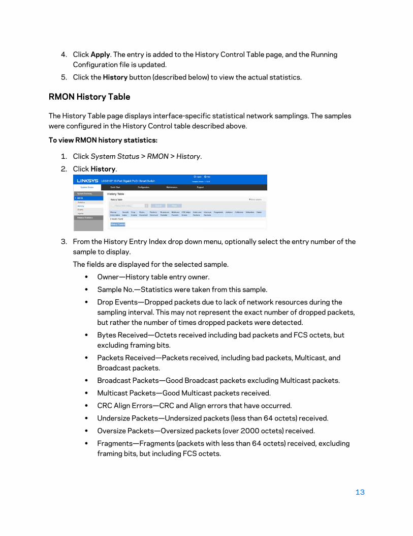
RMON History Table
The History Table page displays interface-specific statistical network samplings. The samples were configured in the History Control table described above.
To view RMON history statistics:
1. Click System Status > RMON > History.
2. Click History.
3. From the History Entry Index drop down menu, optionally select the entry number of the sample to display.
The fields are displayed for the selected sample.
• Owner—History table entry owner.
• Sample No.—Statistics were taken from this sample.
• Drop Events—Dropped packets due to lack of network resources during the sampling interval. This may not represent the exact number of dropped packets, but rather the number of times dropped packets were detected.
• Bytes Received—Octets received including bad packets and FCS octets, but excluding framing bits.
• Packets Received—Packets received, including bad packets, Multicast, and Broadcast packets.
• Broadcast Packets—Good Broadcast packets excluding Multicast packets.
• Multicast Packets—Good Multicast packets received.
• CRC Align Errors—CRC and Align errors that have occurred.
• Undersize Packets—Undersized packets (less than 64 octets) received.
• Oversize Packets—Oversized packets (over 2000 octets) received.
• Fragments—Fragments (packets with less than 64 octets) received, excluding framing bits, but including FCS octets.

14
• Jabbers—Total number of received packets that were longer than 2000 octets. This number excludes frame bits, but includes FCS octets that had either a bad FCS (Frame Check Sequence) with an integral number of octets (FCS Error) or a bad FCS with a non-integral octet (Alignment Error) number.
• Collisions—Collisions received.
• Utilization—Percentage of current interface traffic compared to maximum traffic that the interface can handle.
RMON Events
You can control the occurrences that trigger an alarm and the type of notification that occurs.
• Events Page—Configures what happens when an alarm is triggered. This can be any combination of logs and traps.
• Alarms Page—Configures the occurrences that trigger an alarm.
To define RMON events:
1. Click System Status > RMON > Events.
This page displays previously defined events.
2. Click Add.
3. Enter the parameters.
• Event Entry Index —Displays the event entry index number for the new entry.
• Community—Enter the SNMP community string to be included when traps are sent (optional). Note that the community must be defined using the Defining SNMPv1 and v2 Notification Recipients or Defining SNMPv3 Notification Recipients pages for the trap to reach the Network Management Station
• Description—Enter a name for the event. This name is used in the Add RMON Alarm page to attach an alarm to an event.
• Notification Type—Select the type of action that results from this event. o None—No action occurs when the alarm goes off. o Log (Event Log Table)—Add a log entry to the Event Log table when the
alarm is triggered.
15
o Trap (SNMP Manager and SYSLOG Server)—Send a trap to the remote log server when the alarm goes off.
o Log and Trap—Add a log entry to the Event Log table and send a trap to the remote log server when the alarm goes off.
• Last Event Time—Displays the time of the event. (This is a read-only table in the parent window and cannot be defined).
• Owner—Enter the device or user that defined the event.
4. Click Apply. The RMON event is saved to the Running Configuration file.
5. Click Event Log to display the log of alarms that have occurred and that have been logged (see description below).
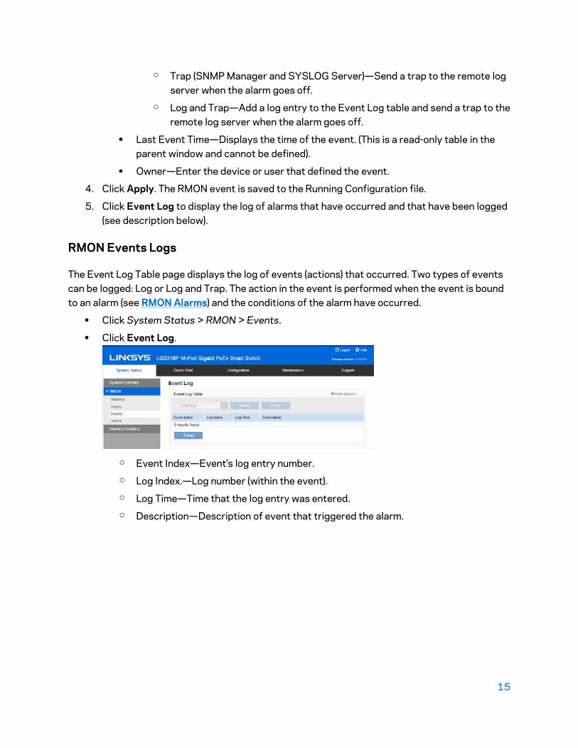
RMON Events Logs
The Event Log Table page displays the log of events (actions) that occurred. Two types of events can be logged: Log or Log and Trap. The action in the event is performed when the event is bound to an alarm (see RMON Alarms) and the conditions of the alarm have occurred.
• Click System Status > RMON > Events.
• Click Event Log.
o Event Index—Event’s log entry number. o Log Index.—Log number (within the event). o Log Time—Time that the log entry was entered. o Description—Description of event that triggered the alarm.

16
RMON Alarms
RMON alarms provide a mechanism for setting thresholds and sampling intervals to generate exception events on counters or any other SNMP object counter maintained by the agent. Both the rising and falling thresholds must be configured in the alarm. After a rising threshold is crossed, no rising events are generated until the companion falling threshold is crossed. After a falling alarm is issued, the next alarm is issued when a rising threshold is crossed.
One or more alarms are bound to an event, which indicates the action to be taken when the alarm occurs.
Alarm counters can be monitored by either absolute values or changes (delta) in the counter values.
To enter RMON alarms:
1. Click System Status > RMON > Alarms. All previously-defined alarms are displayed. The fields are described in the Add RMON Alarm page below.
• Counter Value—Displays the value of the statistic during the last sampling period.
2. Click Add.
3. Enter the parameters.
• Alarm Entry Index—Displays the alarm entry number.
• Interface—Select the type of interface for which RMON statistics are displayed.
• Counter Name—Select the MIB variable that indicates the type of occurrence measured.
• Sample Type—Select the sampling method to generate an alarm. The options are: o Absolute—If the threshold is crossed, an alarm is generated. o Delta—Subtracts the last sampled value from the current value. The
difference in the values is compared to the threshold. If the threshold was crossed, an alarm is generated.
o Interval—Enter the alarm interval time in seconds.
• Rising Event—Select an event to be performed when a rising event is triggered. Events are created in the Events page.
• Rising Threshold—Enter the value that triggers the rising threshold alarm
• Falling Event—Select an event to be performed when a falling event is triggered.

17
• Falling Threshold—Enter the value that triggers the falling threshold alarm.
• Startup Alarm—Select the first event from which to start generation of alarms. Rising is defined by crossing the threshold from a low-value threshold to a higher-value threshold.
o Rising Alarm—A rising value triggers the rising threshold alarm. o Falling Alarm—A falling value triggers the falling threshold alarm. o Rising and Falling—Both rising and falling values trigger the alarm.
• Owner—Enter the name of the user or network management system that receives the alarm.
4. Click Apply. The RMON alarm is saved to the Running Configuration file.
Interface Statistics
The Interface Statistics page displays traffic statistics per port. The refresh rate of the information can be selected.
This page is useful for analyzing the amount of traffic that is both sent and received and its dispersion (Unicast, Multicast, and Broadcast).

18
To display Ethernet statistics and/or set the refresh rate:
1. Click System Status > Interface Statistics.
2. Enter the parameters. o Interface—Select the specific interface for which Ethernet statistics are to be
displayed. o Refresh Rate—Select the time period that passes before the interface Ethernet
statistics are refreshed. The available options are as follows: - No Refresh—Statistics are not refreshed. - 15 Sec—Statistics are refreshed every 15 seconds. - 30 Sec—Statistics are refreshed every 30 seconds. - 60 Sec—Statistics are refreshed every 60 seconds.
o Total Octets—Octets received, including bad packets and FCS octets, but excluding framing bits.
o Unicast Packets—Good Unicast packets received. o Multicast Packets—Good Multicast packets received. o Broadcast Packets—Good Broadcast packets received. o Error Packets—Packets with errors received. o Total Octets—Octets transmitted, including bad packets and FCS octets, but
excluding framing bits. o Unicast Packets—Good Unicast packets transmitted. o Multicast Packets—Good Multicast packets transmitted. o Broadcast Packets—Good Broadcast packets transmitted.
To clear or view statistics counters:
• Click Refresh to refresh the counters on the page.
• Click Clear to clear the selected interfaces counters.
• Click View All to see all ports on a single page.
19
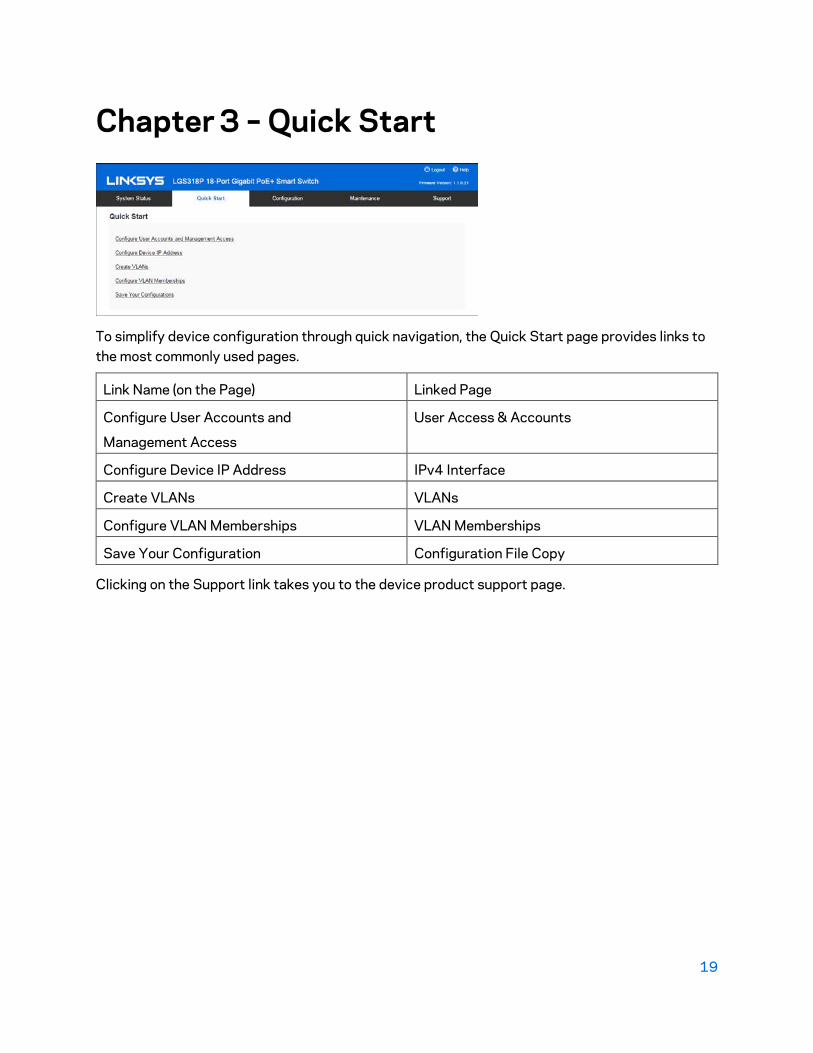
Chapter 3 – Quick Start
To simplify device configuration through quick navigation, the Quick Start page provides links to the most commonly used pages.
Link Name (on the Page) Linked Page
Configure User Accounts and
Management Access
User Access & Accounts
Configure Device IP Address IPv4 Interface
Create VLANs VLANs
Configure VLAN Memberships VLAN Memberships
Save Your Configuration Configuration File Copy
Clicking on the Support link takes you to the device product support page.
20
Chapter 4 – System Management
System Information
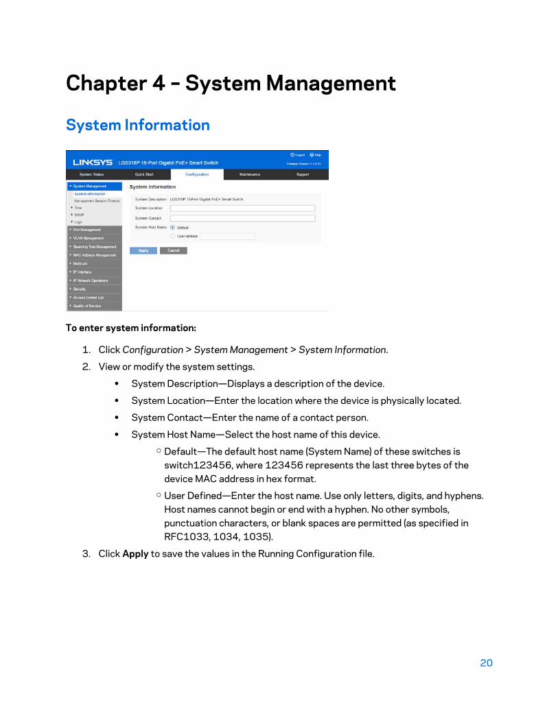
To enter system information:
1. Click Configuration > System Management > System Information.
2. View or modify the system settings.
• System Description—Displays a description of the device.
• System Location—Enter the location where the device is physically located.
• System Contact—Enter the name of a contact person.
• System Host Name—Select the host name of this device. o Default—The default host name (System Name) of these switches is
switch123456, where 123456 represents the last three bytes of the device MAC address in hex format.
o User Defined—Enter the host name. Use only letters, digits, and hyphens. Host names cannot begin or end with a hyphen. No other symbols, punctuation characters, or blank spaces are permitted (as specified in RFC1033, 1034, 1035).
3. Click Apply to save the values in the Running Configuration file.

21
Management Session Timeout
The Management Session Timeout configures the time intervals that the management sessions can remain idle before they timeout and you must log in again to reestablish the session.
To set the idle session timeout for various types of sessions:
1. Click Configuration > System Management > Management Session Timeout.
2. Select the timeout for the following sessions from the corresponding list. The default timeout value is 10 minutes.
• Telnet Session Timeout—Select the timeout for a Telnet session.
• HTTP Session Timeout—Select the timeout for an HTTP session.
• HTTPs Session Timeout—Select the timeout for an HTTPS session.
3. Click Apply to set the configuration settings on the device.
Time
Network time synchronization is critical because every aspect of managing, securing, planning, and debugging a network involves determining when events occur. Without synchronized clocks, accurately correlating log files between devices when tracking security breaches or network usage is impossible.
Synchronized time also reduces confusion in shared file systems, as it is important for the modification times to be consistent, regardless of the machine on which the file systems reside.
For these reasons, it is important that the time configured on all of the devices on the network is accurate.
Note—The device supports Simple Network Time Protocol (SNTP) and when enabled, the device dynamically synchronizes the device time with time from an SNTP server. The device operates only as an SNTP client, and cannot provide time services to other devices.

22
Clock Source
System time can be set manually by the user, or dynamically from an SNTP server. If an SNTP server is chosen, the manual time settings are overwritten when communications with the server are established.
As part of the boot process, the device always configures the time, time zone, and DST. These parameters are obtained from SNTP, values set manually, or if all else fails, from the factory defaults.
• Manual—User must manually set the time.
• SNTP—Time can be received from SNTP time servers. SNTP ensures accurate network time synchronization of the device up to the millisecond by using an SNTP server for the clock source. When specifying an SNTP server, if choosing to identify it by hostname, three suggestions are given in the GUI:
o time-a.timefreq.bldrdoc.gov o time-b.timefreq.bldrdoc.gov o time-c.timefreq.bldrdoc.gov
Note—SNTP is the recommended method for time setting.
SNTP Modes
The device can receive system time from an SNTP server in one of the following ways:
• Client Broadcast Reception (passive mode)—SNTP servers broadcast the time, and the device listens to these broadcasts. When the device is in this mode, there is no need to define a Unicast SNTP server.
• Client Broadcast Transmission (active mode)—The device, as an SNTP client, periodically requests SNTP time updates. This mode works in either of the following ways:
o SNTP Anycast Client Mode—The device broadcasts time request packets to all SNTP servers in the subnet, and waits for a response.
o Unicast SNTP Server Mode—The device sends Unicast queries to a list of manually-configured SNTP servers, and waits for a response.
The device supports having all of the above modes active at the same time and selects the best system time received from an SNTP server, according to an algorithm based on the closest stratum (distance from the reference clock).
Time Zone and Daylight Savings Time (DST)
The Time Zone and DST can be set on the device in the following ways:
• Dynamic configuration of the device through a DHCP server, where:
• Dynamic DST, when enabled and available, always takes precedence over the manual configuration of DST.
23
• If the server supplying the source parameters fails, or dynamic configuration is disabled by the user, the manual settings are used.
• Dynamic configuration of the time zone and DST continues after the IP address lease time has expired.
• Manual configuration of the time zone and DST becomes the Operational time zone and DST, only if the dynamic configuration is disabled or fails.
Note—The DHCP server must supply DHCP option 100 in order for dynamic time zone configuration to take place.
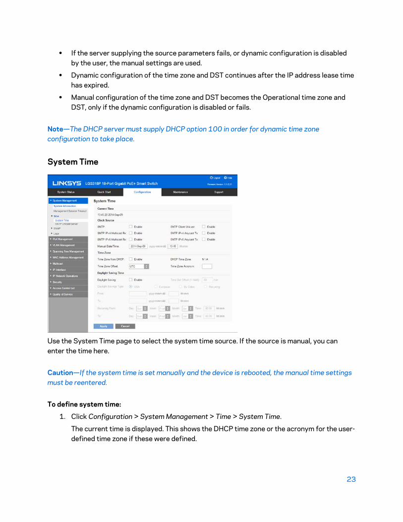
System Time
Use the System Time page to select the system time source. If the source is manual, you can enter the time here.
Caution—If the system time is set manually and the device is rebooted, the manual time settings must be reentered.
To define system time:
1. Click Configuration > System Management > Time > System Time.
The current time is displayed. This shows the DHCP time zone or the acronym for the user-defined time zone if these were defined.
24
2. Enter these parameters:
Clock Source
• SNTP-If you enable this, the system time is obtained from an SNTP server.
To use this feature, you must also configure a connection to an SNTP server in the SNTP Unicast Server page.
• SNTP Client Unicast-Select to enable client Unicast mode.
• SNTP IPv4 Multicast Rx-Select to receive SNTP IPv4 Multicast synchronization packets requesting system time information. The packets are transmitted to all SNTP servers on the subnet.
• SNTP IPv4 Anycast Tx-Select to transmit SNTP IPv4 Anycast synchronization packets requesting system time information. The packets are transmitted from any SNTP servers on the subnet.
• SNTP IPv6 Multicast Rx-Select to receive SNTP IPv6 Multicast synchronization packets requesting system time information. The packets are transmitted to all SNTP servers on the subnet.
• SNTP IPv6 Anycast Tx-Select to transmit SNTP IPv6 Anycast synchronization packets requesting system time information. The packets are transmitted from any SNTP servers on the subnet.
• Manual Date/Time-Set the date and time manually. The local time is used when there is no alternate source of time, such as an SNTP server.
Time Zone
• Time Zone from DHCP-Select to enable dynamic configuration of the time zone and the DST from the DHCP server. Whether one or both of these parameters can be configured depends on the information found in the DHCP packet. If this option is enabled, you must also enable DHCP client on the device. The DHCP Client supports Option 100 providing dynamic time zone setting.
• DHCP Time Zone-Displays the acronym of the time zone configured from the DHCP server. This acronym appears in the Actual Time field.
• Time Zone Offset-Select the difference in hours between Greenwich Mean Time (GMT) and the local time. For example, the Time Zone Offset for Paris is GMT +1, while the Time Zone Offset for New York is GMT - 5.
• Time Zone Acronym-Enter a user-defined name that represents the time zone you have configured. This acronym appears in the Actual Time field.
Daylight Savings Time
Select to enable Daylight Saving Time.
• Time Set Offset-Enter the number of minutes offset from GMT ranging from1-1440. The default is 60.

25
• Daylight Savings Type o USA - DST is set according to the dates used in the USA. o European - DST is set according to the dates used by the European Union
and other countries that use this standard. o By Dates - DST is set manually, typically for a country other than the USA
or a European country. This allows customization of the start and stop of DST.
- From - Date and time that DST starts. - To - Date and time that DST ends.
o Recurring From / Recurring To) - DST occurs on the same date every year. This allows customization of the start and stop of DST
- Day - Day of the week on which DST begins every year. - Week - Week within the month from which DST begins every year. - Month - Month of the year in which DST begins every year. - Time - The time at which DST begins every year.
3. Click Apply. The system time values are written to the Running Configuration file.
SNTP Unicast Server
Up to 16 Unicast SNTP servers can be configured.
Note—To specify a Unicast SNTP server by name, you must first configure DNS server(s) on the device (see Domain Name System). To add a Unicast SNTP server, SNTP Client Unicast must be enabled (in the System Time page).

26
To add a Unicast SNTP server:
1. Click Configuration > System Management > Time > SNTP Unicast Server.
This page displays the following information for each Unicast SNTP server:
• SNTP Server—SNTP server IP address. The preferred server, or hostname, is chosen according to its stratum level.
• SNTP Server Status—SNTP server status. The possible values are: - Up—SNTP server is currently operating normally. - Down—SNTP server is currently not available. - Unknown—SNTP server is currently being searched for by the device. - In Process—Occurs when the SNTP server does not fully trust its own time
server (i.e. when first booting up the SNTP server).
• Stratum Level—Distance from the reference clock expressed as a numerical value. An SNTP server cannot be the primary server (stratum level 1) unless polling interval is enabled.
• Offset—Estimated offset of the server's clock relative to the local clock, in milliseconds. The host determines the value of this offset using the algorithm described in RFC 2030.
• Delay—Estimated round-trip delay of the server's clock relative to the local clock over the network path between them, in milliseconds. The host determines the value of this delay using the algorithm described in RFC 2030.
• Poll Interval—Displays whether polling is enabled or disabled.
• Authentication Key ID—Key Identification used to communicate between the SNTP server and device.
• Last Response Time—Last date and time a response was received from this SNTP server.
2. To add a Unicast SNTP server, enable SNTP Client Unicast.
3. Click Add.
4. Enter the following parameters:
• SNTP Server—Select if the SNTP server is going to be identified by its IP address or if you are going to select a well-known SNTP server by name from the list.
Note—To specify a well-known SNTP server, the device must be connected to the internet and configured with a DNS server or configured so that a DNS server is identified by using DHCP. (See Domain Name System in Chapter 11.)
• IP Version—Select the version of the IP address: Version 6 or Version 4.
• IPv6 Address Type—Select the IPv6 address type (if IPv6 is used). The options are
27
• Link Local—The IPv6 address uniquely identifies hosts on a single network link. A link local address has a prefix of FE80, is not routable, and can be used for communication only on the local network. Only one link local address is supported. If a link local address exists on the interface, this entry replaces the address in the configuration.
• Link Local Interface—Select the link local interface (if IPv6 AddressType Link Local is selected) from the list.
• Global—The IPv6 address is a global Unicast IPV6 type that is visible and reachable from other networks.
• SNTP Server IP Address—Enter the SNTP server IP address. The format depends on which address type was selected.
• SNTP Server Name—Select the name of the SNTP server from a list of well-known NTP servers. If other is chosen, enter the name of an SNTP server in the adjacent field.
• Poll Interval—Select to enable polling of the SNTP server for system time information. All NTP servers that are registered for polling are polled, and the clock is selected from the server with the lowest stratum level (distance from the reference clock) that is reachable. The server with the lowest stratum is considered to be the primary server. The server with the next lowest stratum is a secondary server, and so forth. If the primary server is down, the device polls all servers with the polling setting enabled, and selects a new primary server with the lowest stratum.
5. Click Apply. The STNP server is added, and you are returned to the main page.
SNMP
This section describes the Simple Network Management Protocol (SNMP) feature that provides a method for managing network devices.
SNMP Versions
The device functions as an SNMP agent and supports SNMPv1, v2, and v3. It also reports system events to trap receivers using the traps defined in the supported MIBs (Management Information Base).
• SNMPv1 and v2
To control access to the system, a list of community entries is defined. Each community entry consists of a community string and its access privilege. The system responds only to SNMP messages specifying the community which has the correct permissions and correct operation.
SNMP agents maintain a list of variables that are used to manage the device. These variables are defined in the Management Information Base (MIB).

28
Note—Due to the security vulnerabilities of other versions, it is recommended to use SNMPv3.
• SNMPv3
In addition to the functionality provided by SNMPv1 and v2, SNMPv3 applies access control and new trap mechanisms to SNMPv1 and SNMPv2 PDUs. SNMPv3 also defines a User Security Model (USM) that includes:
o Authentication—Provides data integrity and data origin authentication. o Privacy—Protects against disclosure message content. Cipher Block- Chaining
(CBC-DES) is used for encryption. Either authentication alone can be enabled on an SNMP message, or both authentication and privacy can be enabled on an SNMP message. However, privacy cannot be enabled without authentication.
o Timeliness—Protects against message delay or playback attacks. The SNMP agent compares the incoming message time stamp to the message arrival time.
SNMP Workflow
Note—For security reasons, SNMP is disabled by default. Before you can manage the device via SNMP, you must turn on SNMP in the SNMP > Feature Configuration page.
If you decide to use SNMPv1 or v2:
1. Navigate to the SNMP -> Communities page and click Add. The community can be associated with access rights and a view in Basic mode or with a group in Advanced mode. There are two ways to define access rights of a community:
• Basic mode—The access rights of a community can configure with Read Only, Read Write, or SNMP Admin. In addition, you can restrict the access to the community to only certain MIB objects by selecting a view (defined in the Views page).
• Advanced Mode—The access rights of a community are defined by a group (defined in the Groups page). You can configure the group with a specific security model. The access rights of a group are Read, Write, and Notify.
2. Choose whether to restrict the SNMP management station to one address or allow SNMP management from all addresses. If you choose to restrict SNMP management to one address, then input the address of your SNMP Management PC in the IP Address field.
3. Input the unique community string in the Community String field.
4. Optionally, enable traps by using the Trap Settings page.
5. Optionally, define a notification filter(s) by using the Notification Filter page.
6. Configure the notification recipients on the Notification Recipients SNMPv1, v2 page.

29
If you decide to use SNMPv3:
1. Define the SNMP engine by using the Engine ID page. Either create a unique Engine ID or use the default Engine ID. Applying an Engine ID configuration clears the SNMP database.
2. Optionally, define SNMP view(s) by using the Views page. This limits the range of Object IDs available to a community or group.
3. Define groups by using the Groups page.
4. Define users by using the SNMP Users page, where they can be associated with a group. If the SNMP Engine ID is not set, then users may not be created.
5. Optionally, enable or disable traps by using the Trap Settings page.

30
6. Optionally, define a notification filter(s) by using the Notification Filter page.
7. Define a notification recipient(s) by using the Notification Recipients SNMPv3 page.
Device Model Object IDs (OIDs):
Mode Name Description Object ID
LGS308
8-Port Smart Gigabit Switch enterprises(1) . linksys(3955) . smb(1000).3.8.1
LGS318 18-Port Smart Gigabit Switch enterprises(1) . linksys(3955) .
smb(1000).3.18.1
LGS326 26-Port Smart Gigabit Switch enterprises(1) . linksys(3955) .
smb(1000).3.26.1
LGS308P 8-Port Smart Gigabit PoE+ Switch enterprises(1) . linksys(3955) .
smb(1000).3.8.2
LGS318P 18-Port Smart Gigabit PoE+ Switch enterprises(1) . linksys(3955) .
smb(1000).3.18.2
LGS326P 26-Port Smart Gigabit PoE+ Switch enterprises(1) . linksys(3955) . smb(1000).3.26.
Private OIDs are placed under: enterprises(1).linksys(3955).smb(1000).switch01(201).
31
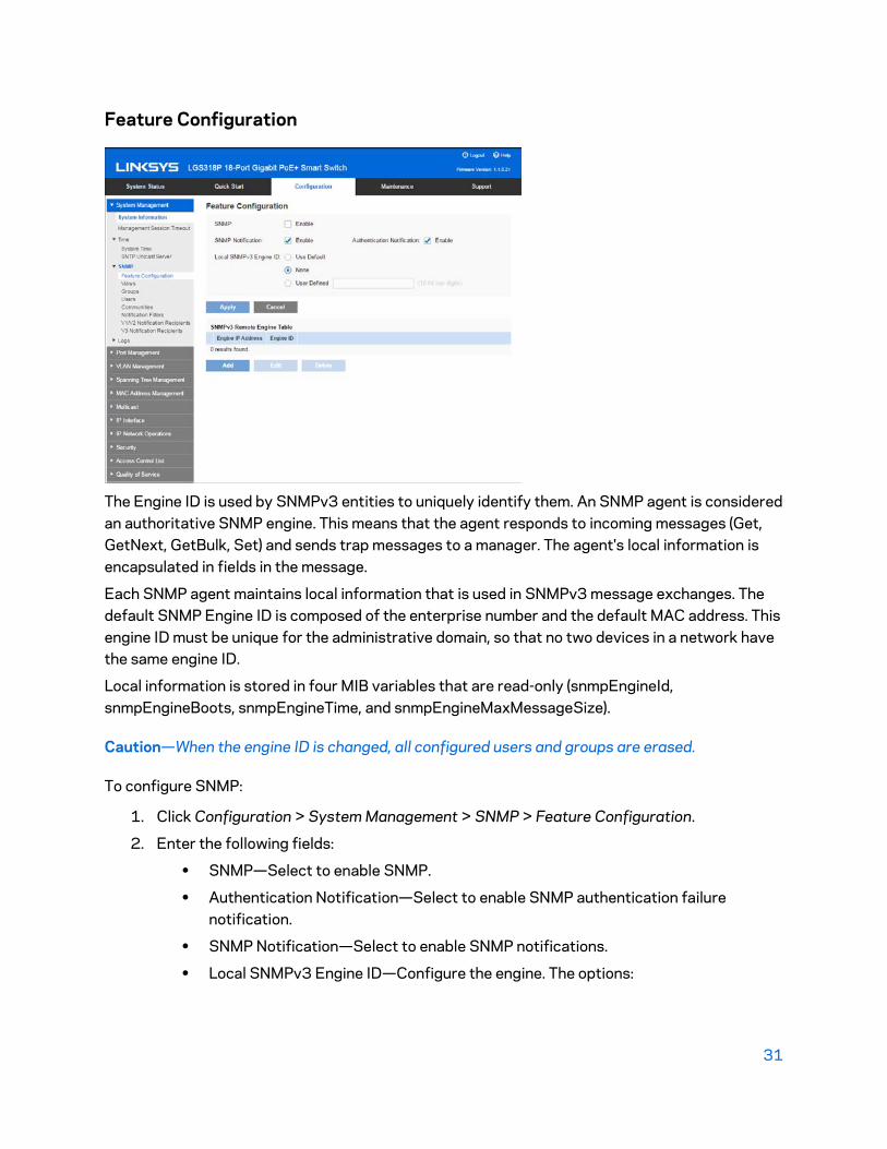
Feature Configuration
The Engine ID is used by SNMPv3 entities to uniquely identify them. An SNMP agent is considered an authoritative SNMP engine. This means that the agent responds to incoming messages (Get, GetNext, GetBulk, Set) and sends trap messages to a manager. The agent's local information is encapsulated in fields in the message.
Each SNMP agent maintains local information that is used in SNMPv3 message exchanges. The default SNMP Engine ID is composed of the enterprise number and the default MAC address. This engine ID must be unique for the administrative domain, so that no two devices in a network have the same engine ID.
Local information is stored in four MIB variables that are read-only (snmpEngineId, snmpEngineBoots, snmpEngineTime, and snmpEngineMaxMessageSize).
Caution—When the engine ID is changed, all configured users and groups are erased.
To configure SNMP:
1. Click Configuration > System Management > SNMP > Feature Configuration.
2. Enter the following fields:
• SNMP—Select to enable SNMP.
• Authentication Notification—Select to enable SNMP authentication failure notification.
• SNMP Notification—Select to enable SNMP notifications.
• Local SNMPv3 Engine ID—Configure the engine. The options:

32
o Use Default—Select to use the device-generated engine ID. The default engine ID is based on the device MAC address, and is defined per standard as:
- First 4 octets—First bit = 1, the rest is the IANA enterprise number. - Fifth octet—Set to 3 to indicate the MAC address that follows. - Last 6 octets—MAC address of the device. - None—No engine ID is used.
o User Defined—Enter the local device engine ID. The field value is a hexadecimal string (range: 10 - 64). Each byte in the hexadecimal character strings is represented by two hexadecimal digits.
All remote engine IDs and their IP addresses are displayed in the Remote Engine ID table.
3. Click Apply. The Running Configuration file will be updated.
The Remote Engine ID table shows the mapping between IP addresses of the engine and Engine ID. To add the IP address of an engine ID:
4. Click Add. Enter the following fields:
• Remote Engine IP Address—Select whether to specify the Engine ID server by IP address or name.
• IP Version—Select the supported IP format.
• IPv6 Address Type—Select the IPv6 address type (if IPv6 is used). The options are: o Link Local—The IPv6 address uniquely identifies hosts on a single network
link. A link local address has a prefix of FE80, is not routable, and can be used for communication only on the local network. Only one link local address is supported. If a link local address exists on the interface, this entry replaces the address in the configuration.
o Global—The IPv6 address is a global Unicast IPV6 type that is visible and reachable from other networks.
• Remote Engine IP Address—Enter the IP address of the log server.
• Remote Engine IP Name—Enter the domain name of the log server.
• Engine ID—Enter the Engine ID.
5. Click Apply. The Running Configuration file is updated.

33
Views
A view is a user-defined label for a collection of MIB subtrees. Each subtree ID is defined by the Object ID (OID) of the root of the relevant subtrees. Either well- known names can be used to specify the root of the desired subtree or an OID can be entered (see Device Model Object IDs).
Each subtree is either included or excluded in the view being defined.
The Views page enables creating and editing SNMP views. The default views (Default, DefaultSuper) cannot be changed.
Views can be attached to groups in the Groups page or to a community which employs basic access mode through the Communities page.
To define SNMP views:
1. Click Configuration > System Management > SNMP > Views.
2. Click Add to define new views.
3. Enter the parameters.
• View Name—Enter a view name between 0-30 characters.
• View Object—Select the node in the MIB tree that is included or excluded in the selected SNMP view. The options to select the object are as follows:
o Object ID—Enter an OID not offered in the Object ID Selection List option. o Object ID Selection List—Enables you to navigate the MIB tree. Press the
Up arrow to go to the level of the selected node's parent and siblings; press the Down arrow to descend to the level of the selected node's children. Click nodes in the view to pass from one node to its sibling. Use the scrollbar to bring siblings in view.

34
4. Include or exclude the MIB object from the view. If Include Object is selected, the MIB objects are included in the view, otherwise they are excluded.
5. Click Apply.
6. In order to verify your view configuration, select the user-defined views from the View Name list. The following views exist by default:
• Default—Default SNMP view for read and read/write views.
• DefaultSuper—Default SNMP view for administrator views. Other views can be added.
• Object ID—Displays the Object ID and its subtree to be included or excluded in the SNMP view.
• Object View—Displays whether the defined object and its subtree are included or excluded in the selected SNMP view.
Groups
In SNMPv1 and SNMPv2, a community string is sent along with the SNMP frames. The community string acts as a password to gain access to an SNMP agent. However, neither the frames nor the community string are encrypted. Therefore, SNMPv1 and SNMPv2 are not secure.
In SNMPv3, the following security mechanisms can be configured:
• Authentication—The device checks that the SNMP user is an authorized system administrator. This is done for each frame.
• Privacy—SNMP frames can carry encrypted data. Thus, in SNMPv3, there are three levels of security:
• No security (No authentication and no privacy)
• Authentication (Authentication and no privacy)
• Authentication and privacy
35
SNMPv3 provides a means of controlling the content each user can read or write and the notifications they receive. A group defines read/write privileges and a level of security. It becomes operational when it is associated with an SNMP user or community.
Note—To associate a non-default view with a group, first create the view in the Views page.
To create an SNMP group:
1. Click Configuration > System Management>SNMP > Groups.
This page displays the existing SNMP groups and their security levels. The following fields are displayed for each SNMP group (only the fields not explained in the Add page):
• No Authentication Read View—No authentication is needed, and anyone is able to read the view.
• No Authentication Write View—No authentication is needed, and anyone is able to write the view.
• No Authentication Notify View—No authentication is needed, and anyone is able to receive notification of the view.
• Authentication Read View—Only authenticated users are allowed to read the view. By default, all users or community of a group can access all the MIB objects. A group can be limited to specific view(s) based on the read, write, notify, authentication and/or privacy configurations.
• Authentication Write View—Only authenticated users are able to write the view. Management access is write for the selected view.
• Authentication Notify View—Only authentication users are allowed to received notification.
• Privacy Read View— When reading the objects in the view, the SNMP messages are encrypted.
• Privacy Write View—When writing the object in the view, the SNMP messages are encrypted.
• Privacy Notify View - Notification on the objects in the view are encrypted.
2. Click Add.
3. Enter the parameters.
• Group Name—Enter a new group name.
• Security Model—Select the SNMP version attached to the group, SNMPv1, v2, or v3.
Three types of views with various security levels can be defined. For each security level, select the views for Read, Write and Notify by entering the following fields:
o Enable—Select this field to enable the Security Level.

36
o Security Level—Define the security level attached to the group. SNMPv1 and SNMPv2 support neither authentication nor privacy. If SNMPv3 is selected, select to enable one of the following:
o No Authentication and No Privacy—Neither the Authentication nor the Privacy security levels are assigned to the group.
o Authorized View—Select the Read, Write and Notify views associated with this group and with the above security level.
o Authentication and No Privacy—Authenticates SNMP messages, and ensures the SNMP message origin is authenticated but does not encrypt them.
o Authorized View—Select the Read, Write and Notify views associated with this group and with the above security level.
o Authentication and Privacy—Authenticates SNMP messages, and encrypts them.
o Authorized View—Select the Read, Write and Notify views associated with this group and with the above security level.
4. Click Apply. The SNMP group is saved to the Running Configuration file.
Users
An SNMP user is defined by the login credentials (username, passwords, and authentication method) and by the context and scope in which it operates by association with a group and an Engine ID.
The configured user has the attributes of its group, and the access privileges configured within the associated view.

37
Groups enable network managers to assign access rights to a group of users instead of to a single user.
A user can only belong to a single group.
To create an SNMPv3 user, the following must first exist:
An engine ID must first be configured on the device. This is done in the Engine ID page.
An SNMPv3 group must be available. An SNMPv3 group is defined in the Groups page.
To display SNMP users and define new ones:
1. Click Configuration > System Management>SNMP > Users.
This page contains existing users.
2. Click Add.
This page provides information for assigning SNMP access control privileges to SNMP users.
3. Enter the parameters.
• User Name—Enter a name for the user.
• Engine ID—Select either the local or remote SNMP entity to which the user is connected. Changing or removing the local SNMP Engine ID deletes the SNMPv3 User Database. To receive inform messages and request information, you must define both a local and remote user.
o Local—User is connected to the local device. o Engine—User is connected to a different SNMP entity besides the local
device. If the remote Engine ID is defined, remote devices receive inform messages, but cannot make requests for information.
Select the remote engine ID.
• Group Name—Select the SNMP group to which the SNMP user belongs. SNMP groups are defined in the Add Group page.
Note—Users, who belong to groups which have been deleted, remain, but they are inactive.
• Authentication Method—Select the Authentication method that varies according to the Group Name assigned. If the group does not require authentication, then the user cannot configure any authentication. The options are:
o None—No user authentication is used. o MD5—A password that is used for generating a key by the MD5
authentication method. o SHA—A password that is used for generating a key by the SHA (Secure
Hash Algorithm) authentication method.

38
• Authentication Password—If authentication is accomplished by either a MD5 or a SHA password, enter the local user password in either Encrypted or Plaintext. Local user passwords are compared to the local database, and can contain up to 32 ASCII characters.
• Privacy Method—Select one of the following options: o None—Privacy password is not encrypted. o DES—Privacy password is encrypted according to the Data Encryption
Standard (DES).
• Privacy Password—16 bytes are required (DES encryption key) if the DES privacy method was selected. This field must be exactly 32 hexadecimal characters. The Encrypted or Plaintext mode can be selected.
4. Click Apply to save the settings.
Communities
Access rights in SNMPv1 and SNMPv2 are managed by defining communities in the Communities page. The community name is a type of shared password between the SNMP management station and the device. It is used to authenticate the SNMP management station.
Communities are only defined in SNMPv1 and v2 because SNMPv3 works with users instead of communities. The users belong to groups that have access rights assigned to them.
The Communities page associates communities with access rights, either directly (Basic mode) or through groups (Advanced mode):
• Basic Mode—The access rights of a community can configure with Read Only, Read Write, or SNMP Admin. In addition, you can restrict the access to the community to only certain MIB objects by selecting a view (defined in the SNMP Views page).
39
• Advanced Mode—The access rights of a community are defined by a group (defined in the Groups page). You can configure the group with a specific security model. The access rights of a group are Read, Write, and Notify.
To define SNMP communities:
1. Click Configuration > System Management>SNMP > Communities.
This page contains a table of configured SNMP communities and their properties.
2. Click Add.
This page enables network managers to define and configure new SNMP communities.
3. Enter the following fields:
• SNMP Management Station—Select User Defined to enter the management station IP address that can access the SNMP community. Select All to indicate that any IP device can access the SNMP community.
• IP Version—Select either IPv4 or IPv6.
• IPv6 Address Type—Select the supported IPv6 address type if IPv6 is used. The options are:
o Link Local—The IPv6 address uniquely identifies hosts on a single network link. A link local address has a prefix of FE80, is not routable, and can be used for communication only on the local network. Only one link local address is supported. If a link local address exists on the interface, this entry replaces the address in the configuration.
o Global—The IPv6 address is a global Unicast IPV6 type that is visible and reachable from other networks.
o Interface—If the IPv6 address type is Link Local, select whether it is received through a VLAN or ISATAP.
• IP Address—Enter the SNMP management station IP address.
• Community—Enter the community name used to authenticate the management station to the device.
• Access Control—Select one of the following: o Basic—In this mode, there is no connection to any group. You can only
choose the community access level (Read Only, Read Write, or SNMP Admin) and, optionally, further qualify it for a specific view. By default, it applies to the entire MIB.
o Advanced—In this mode, access is controlled by group configurations.
• Access Mode—Configure the community: o Read Only—Management access is restricted to read-only. Changes
cannot be made to the community.
40
o Read Write—Management access is read-write. Changes can be made to the device configuration, but not to the community.
o SNMP Admin—User has access to all device configuration options, as well as permissions to modify the community. SNMP Admin is equivalent to Read Write for all MIBs except for the SNMP MIBs. SNMP Admin is required for access to the SNMP MIBs.
o View Name—Select an SNMP view (a collection of MIB subtrees to which access is granted).
o Group Name—Select an SNMP group that determines the access rights in Advanced mode.
4. Click Apply. The SNMP Community is defined, and the Running Configuration is updated.
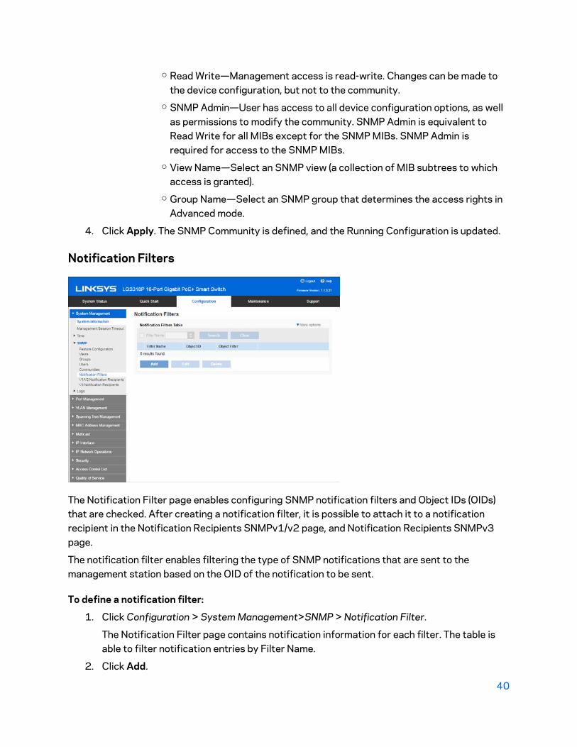
Notification Filters
The Notification Filter page enables configuring SNMP notification filters and Object IDs (OIDs) that are checked. After creating a notification filter, it is possible to attach it to a notification recipient in the Notification Recipients SNMPv1/v2 page, and Notification Recipients SNMPv3 page.
The notification filter enables filtering the type of SNMP notifications that are sent to the management station based on the OID of the notification to be sent.
To define a notification filter:
1. Click Configuration > System Management>SNMP > Notification Filter.
The Notification Filter page contains notification information for each filter. The table is able to filter notification entries by Filter Name.
2. Click Add.

41
3. Enter the parameters.
• Filter Name—Enter a name between 0-30 characters.
• Filter Object—Select the node in the MIB tree that is included or excluded in the selected SNMP filter. The options to select the object are as follows:
o Selection List—Enables you to navigate the MIB tree. Press the Up arrow to go to the level of the selected node's parent and siblings; press the Down arrow to descend to the level of the selected node's children. Click nodes in the view to pass from one node to its sibling. Use the scrollbar to bring siblings in view.
o If Object ID is used, the object identifier is included in the view if the Include in filter option is selected.
4. Include or exclude in Object Filter. If this is selected, the selected MIBs are included in the filter, otherwise they are excluded.
5. Click Apply. The SNMP views are defined and the running configuration is updated.
V1/V2 Notification Recipients
Trap messages are generated to report system events, as defined in RFC 1215. The system can generate traps defined in the MIB that it supports.
Trap receivers (aka Notification Recipients) are network nodes where the trap messages are sent by the device. A list of notification recipients are defined as the targets of trap messages.
A trap receiver entry contains the IP address of the node and the SNMP credentials corresponding to the version that is included in the trap message. When an event arises that requires a trap message to be sent, it is sent to every node listed in the Notification Recipient Table.
42
The Notification Recipients SNMPv1/v2 page and the Notification Recipients SNMPv3 page enable configuring the destination to which SNMP notifications are sent, and the types of SNMP notifications that are sent to each destination (traps or informs). The Add/Edit pop-ups enable configuring the attributes of the notifications.
An SNMP notification is a message sent from the device to the SNMP management station indicating that a certain event has occurred, such as a link up/ down.
It is also possible to filter certain notifications. This can be done by creating a filter in the Notification Filter page and attaching it to an SNMP notification recipient. The notification filter enables filtering the type of SNMP notifications that are sent to the management station based on the OID of the notification that is about to be sent.
To define a recipient in SNMPv1/v2:
1. Click Configuration > System Management >SNMP > Notification Recipients.
This page displays the currently-defined SNMP recipients.
2. Enter the parameters.
• Recipient—Select whether to specify the remote log server by IP address or server name.
• IP Version—Select either IPv4 or IPv6.
• IPv6 Address Type—Select either Link Local or Global. o Link Local—The IPv6 address uniquely identifies hosts on a single network
link. A link local address has a prefix of FE80, is not routable, and can be used for communication only on the local network. Only one link local address is supported. If a link local address exists on the interface, this entry replaces the address in the configuration.
o Global—The IPv6 address is a global Unicast IPV6 type that is visible and reachable from other networks.
o Interface—If the IPv6 address type is Link Local, select whether it is received through a VLAN or ISATAP.
• Recipient IP Address—Enter the IP address of where the traps are sent.
• Recipient IP Name—Enter the server name of where the traps are sent.
• UDP Port—Enter the UDP port used for notifications on the recipient device.
• Notification Type—Select whether to send Traps or Informs. If both are required, two recipients must be created.
• Notification Version—Select the trap SNMP version 1 or 2.
• Community—Select from the pull-down the community string of the trap manager. Community String names are generated from those listed in the Community page.
• Notification Filter—Select to enable filtering the type of SNMP notifications sent to the management station. The filters are created in the Notification Filter page.
43
• Filter Name—Select the SNMP filter that defines the information contained in traps (defined in the Notification Filter page).
3. Click Apply. The SNMP Notification Recipient settings are written to the Running Configuration file.
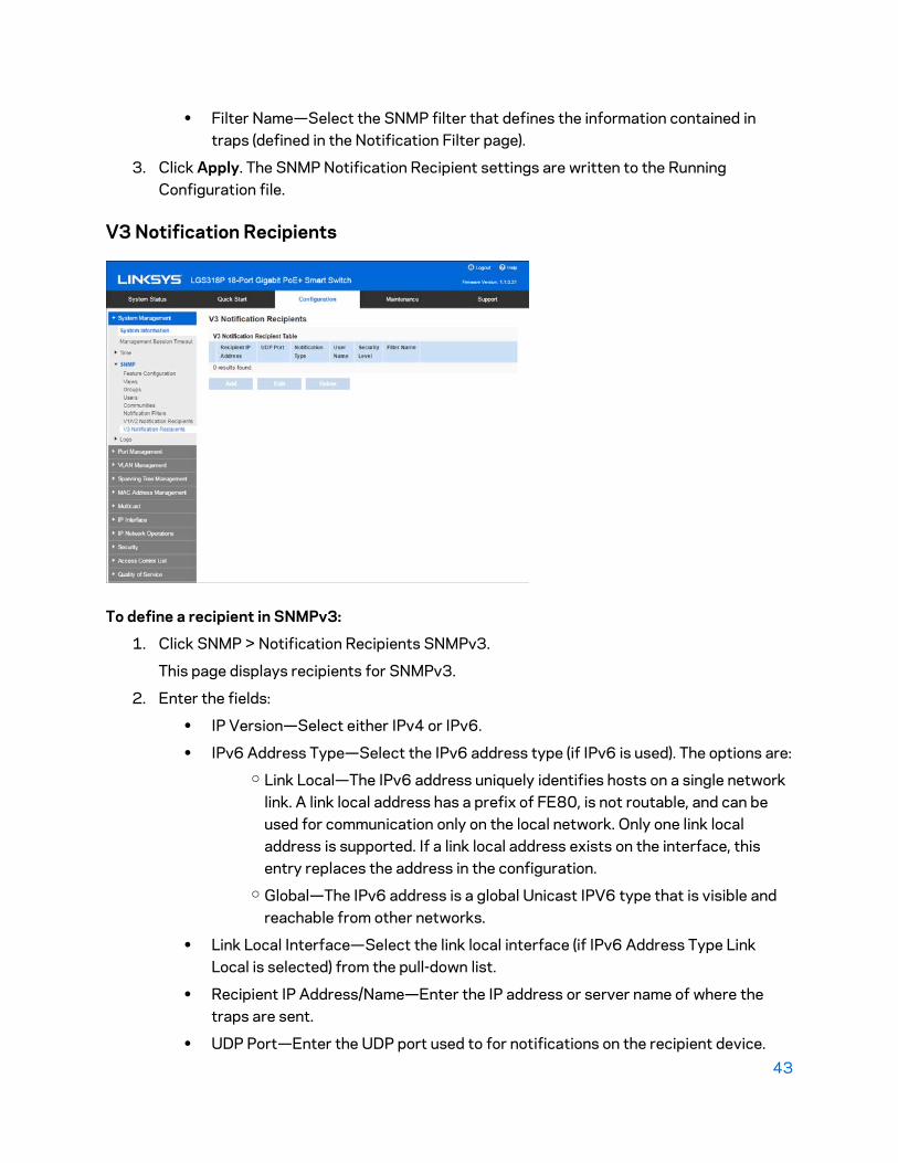
V3 Notification Recipients
To define a recipient in SNMPv3:
1. Click SNMP > Notification Recipients SNMPv3.
This page displays recipients for SNMPv3.
2. Enter the fields:
• IP Version—Select either IPv4 or IPv6.
• IPv6 Address Type—Select the IPv6 address type (if IPv6 is used). The options are: o Link Local—The IPv6 address uniquely identifies hosts on a single network
link. A link local address has a prefix of FE80, is not routable, and can be used for communication only on the local network. Only one link local address is supported. If a link local address exists on the interface, this entry replaces the address in the configuration.
o Global—The IPv6 address is a global Unicast IPV6 type that is visible and reachable from other networks.
• Link Local Interface—Select the link local interface (if IPv6 Address Type Link Local is selected) from the pull-down list.
• Recipient IP Address/Name—Enter the IP address or server name of where the traps are sent.
• UDP Port—Enter the UDP port used to for notifications on the recipient device.

44
• Notification Version—Select SNMP v3.
• Notification Type—Select whether to send traps or informs. If both are required, two recipients must be created.
• Timeout—Enter the amount of time (seconds) the device waits before re- sending informs/traps. Timeout: Range 1-300, default 15.
• Retries—Enter the number of times that the device resends an inform request. Retries: Range 1-255, default 3.
• User Name—Select from the drop-down list the user to whom SNMP notifications are sent. In order to receive notifications, this user must be defined on the SNMP User page, and its engine ID must be remote.
• Security Level—Select how much authentication is applied to the packet.
Note—The Security Level here depends on which User Name was selected. If this User Name was configured as No Authentication, the Security Level is No Authentication only. However, if this User Name has assigned Authentication and Privacy on the User page, the security level on this screen can be either No Authentication, or Authentication Only, or Authentication and Privacy.
The options are: o No Authentication—Indicates the packet is neither authenticated nor
encrypted. o Authentication—Indicates the packet is authenticated but not encrypted. o Privacy—Indicates the packet is both authenticated and encrypted.
• Notification Filter—Select to enable filtering the type of SNMP notifications sent to the management station. The filters are created in the Notification Filter page.
• Filter Name—Select the SNMP filter that defines the information contained in traps (defined in the Notification Filter page).
3. Click Apply. The SNMP Notification Recipient settings are written to the Running Configuration file.
Logs
Each log is a set of messages describing system events. The device generates the following local logs:
• Log sent to the console interface.
• Log written into a cyclical list of logged events in the RAM and erased when the device reboots.
• Log written to a cyclical log-file saved to the Flash memory and persists across reboots.

45
In addition, you can send messages to remote SYSLOG servers in the form of SNMP traps and SYSLOG messages.
You can configure the messages that are written to each log by severity, and a message can go to more.
Log Management
You can select the events by severity level. Each log message has a severity level marked with the first letter of the severity level separated by dashes (-) on each side (except for Emergency that is indicated by the letter F). For example, the log message “%INIT-I-InitCompleted: … “ has a severity level of I, meaning Informational.
The event severity levels are listed from the highest severity to the lowest severity:
1. Emergency—System is not usable.
2. Alert—Action is needed.
3. Critical—System is in a critical condition.
4. Error—System is in error condition.
5. Warning—System warning has occurred.
6. Notice—System is functioning properly, but a system notice has occurred.
7. Informational—Device information.
8. Debug—Detailed information about an event.
You can select different severity levels for RAM and Flash logs. These logs are displayed in the RAM Log page and Flash Memory Log page, respectively.
Selecting a severity level to be stored in a log causes all of the higher severity events to be automatically stored in the log. Lower severity events are not stored in the log.
46
For example, if Warning is selected, all severity levels that are Warning and higher are stored in the log (Emergency, Alert, Critical, Error, and Warning). No events with severity level below Warning are stored (Notice, Informational, and Debug).
To set global log parameters:
1. Click Configuration > System Management > Logs > Log Management.
2. Enter the parameters:
• System Log o Logging—Select to enable message logging. o Originator Identifier—Enables adding an origin identifier to SYSLOG
messages. The options: o None—Do not include the origin identifier in SYSLOG messages. o Hostname—Include the system hostname in SYSLOG messages. o IPv4 Address—Include the IPv4 address of the sending interface
inSYSLOG messages. o IPv6 Address—Include the IPv6 address of the sending interface
inSYSLOG messages. o User Defined—Enter a description to be included in SYSLOG messages.
• Log Settings o Severity—Select the severity levels of the messages to be logged to the
following: o RAM Memory Logging—Severity levels of the messages to be logged to
the RAM. o Flash Memory Logging—Severity levels of the messages to be logged to
the Flash memory.
3. Click Apply. The Running Configuration file is updated.

47
Remote Log Servers
The Remote Log Servers page enables defining remote SYSLOG servers where log messages are sent (using the SYSLOG protocol). For each server, you can configure the severity of the messages that it receives.
To define SYSLOG servers, do the following:
1. Click Configuration > System Management > Logs > Remote Log Servers.
2. Click Add.
3. Enter the parameters.
• Enter New Server o Remote Log Server—Select whether to identify the remote log server
by IP address or name. o IP Version—Select the supported IP version. o IPv6 Address Type—Select the IPv6 address type (if IPv6 is used). The
options: - Global—The IPv6 address is a global Unicast IPV6 type that
is visible and reachable from other networks. - Link Local—The IPv6 address uniquely identifies hosts on a
single network link. A link local address has a prefix of FE80, is not routable, and can be used for communication only on the local network. Only one link local address is supported. If a link local address exists on the interface, this entry replaces the address in the configuration.
- Interface—Select the link local interface (if IPv6 Address Type Link Local is selected) from the list.

48
o Log Server IP Address—Enter the IP address of the log server if it is to be identified by address.
o Log Server Name—Enter the domain name of the log server if it is to be identified by name.
• Server Settings o UDP Port—Enter the UDP port to which the log messages are sent. o Facility—Select a facility value from which system logs are sent to the
remote server. Only one facility value can be assigned to a server. If a second facility code is assigned, the first facility value is overridden.
o Description—Enter a server description. o Minimum Logging Level—Select the minimum level of system log
messages to be sent to the server.
4. Click Apply. The SYSLOG server is added, and the Running Configuration file is updated.
RAM Log
The RAM Log page displays all messages that were saved in the RAM (cache) in chronological order. Entries are stored in the RAM log according to the configuration in the Log Management page.
Click Configuration > System Management > Logs > RAM Log.
• Log Index—Log entry number.
• Log Time—Time when message was generated.

49
• Severity—Event severity.
• Description—Message text describing the event.
To clear the log messages, click Clear.
Flash Memory Log
The Flash Memory Log page displays the messages that were stored in the Flash memory, in chronological order. The minimum severity for logging is configured in the Log Management page. Flash logs remain when the device is rebooted. You can clear the logs manually.
Click Configuration > System Management > Logs > Flash Memory Log.
• Log Index—Log entry number.
• Log Time—Time when message was generated.
• Severity—Event severity.
• Description—Message text describing the event.
To clear the messages, click Clear.

50
Chapter 5 – Port Management
Ports
To configure port settings:
1. Click Configuration > Port Management > Ports.
2. Select Enable to support jumbo packets of up to 10 KB in size. If Jumbo Frames is not enabled (default), the system supports packet size up to 2,000 bytes. For Jumbo Frames to take effect, the device must be rebooted after the feature is enabled.
3. To update the port settings, select the desired port, and click Edit.
• Select Your Port o Port—Select the port number from the drop-down menu.
• Port settings o Operational Status—Displays whether the port is up or down. If the
port is down because of an error, the description of the error is
displayed. o Administrative Mode—Select to change the operational status. o Suspended Port—Select to reactivate a port that has been suspended.
The reactivate operation brings the port up without regard to why the
port was suspended.

51
o Protected Port—Select to make this a protected port. (A protected port
is also referred to as a Private VLAN Edge.)
Features of a protected port: - Protected Ports provide Layer 2 isolation between interfaces
(Ethernet ports and LAGs) that share the same VLAN. - Packets received from protected ports can be forwarded only
to unprotected egress ports. Protected port filtering rules are
also applied to packets that are forwarded by software, such as
snooping applications. - Port protection is not subject to VLAN membership. Devices
connected to protected ports are not allowed to communicate
with each other, even if they are members of the same VLAN. - Both ports and LAGs can be defined as protected or
unprotected. - Protected LAGs are described in the LAGs section.
o Auto Negotiation—Select to enable auto-negotiation on the port. Auto
negotiation enables a port to advertise its transmission speed, duplex
mode, and flow control abilities to the port link partner. o Port Speed—Port type determines available speeds. You can designate
this field only when port Auto Negotiation is disabled. o Duplex Mode—Select the port duplex mode. This field is configurable
only when Auto Negotiation is disabled, and the port speed is set to
10M or 100M. At port speed of 1G, the mode is always full duplex. - Half—The interface supports transmission between the device
and the client in only one direction at a time. - Full—The interface supports transmission between the device
and the client in both directions simultaneously. o Auto Advertisement—Select the capabilities advertised by Auto
Negotiation when it is enabled. - Max Capability—All port speeds and duplex mode settings can
be accepted. - 10 Full Duplex—10 Mbps speed and Full Duplex mode. - 10 Half Duplex—10 Mbps speed and Half Duplex mode. - 100 Full Duplex—100 Mbps speed and Full Duplex mode. - 100 Half Duplex—100 Mbps speed and Half Duplex mode. - 1000 Full Duplex—1000 Mbps speed and Full Duplex mode.

52
o Back Pressure—Used with Half Duplex mode to slow down the packet
reception speed when the device is congested. It disables the remote
port, preventing it from sending packets by jamming the signal. o Flow Control—Enable or disable 802.3x Flow Control, or enable the
Auto Negotiation of flow control on the port (only when in Full Duplex
mode). o MDI/MDIX—Media Dependent Interface/Media Dependent o Interface with Crossover status on the port.
- MDIX—Select to swap the port’s transmit and receives pairs. - MDI—Select to connect this device to a station by using a
straight-through cable. - Auto—Select to configure this device to automatically detect
the correct pinouts for the connection to another device. o Description—Enter a port description.
4. Click Apply.
Link Aggregation
Link Aggregation Control Protocol (LACP) is part of the IEEE specification (802.3ad) that enables you to bundle several physical ports together to form a single logical channel (LAG). LAGs multiply
the bandwidth, increase port flexibility, and provide link redundancy between two devices.
This switch supports two kinds of LAG. • Static—A LAG is static if the LACP is disabled. The ports assigned to a static LAG are
always active members. After a LAG is manually created, the LACP option cannot be
added or removed until the LAG is edited and a member is removed (which can be added prior to applying), then the LACP button becomes available for editing.
• Dynamic—A LAG is dynamic if LACP is enabled. The ports assigned to dynamic LAG are
candidate ports. LACP determines which candidate ports are active member ports. The non-active candidate ports are standby ports ready to replace any failing active member
ports.
Load Balancing Traffic forwarded to a LAG is load-balanced across the active member ports, thus achieving an
effective bandwidth close to the aggregate bandwidth of all the active member ports of the LAG.
Traffic load balancing over the active member ports of a LAG is managed by a hash-based distribution function that distributes Unicast and Multicast traffic based on Layer 2 or Layer 3
packet header information.

53
This switch supports two modes of load balancing. • By MAC Addresses—(Default) Based on the destination and source MAC addresses of all
packets. • By IP and MAC Addresses—Based on the destination and source IP addresses for IP
packets, and destination and source MAC addresses for non-IP packets. LAG Management In general, a LAG is treated by the system as a single logical port. In particular, the LAG has port
attributes similar to a regular port, such as state and speed. The device supports four LAGs. Each LAG has the following characteristics:
• All ports in a LAG must be of the same media type. • To add a port to the LAG, it cannot belong to any VLAN except the default VLAN. • Ports in a LAG must not be assigned to another LAG. • No more than eight ports are assigned to a static LAG and no more than 16 ports can be
candidates for a dynamic LAG. • All the ports in a LAG must have auto-negotiation disabled, although the LAG can have
auto-negotiation enabled. • When a port is added to a LAG, the configuration of the LAG is applied to the port. When
the port is removed from the LAG, its original configuration is reapplied. • Protocols, such as Spanning Tree, consider all the ports in the LAG to be one port.
Default Settings and Configuration Ports are not members of a LAG and are not candidates to become part of a LAG.
Static and Dynamic LAG Workflow After a LAG has been manually created, LACP cannot be added or removed until the LAG is edited
and a member is removed. Only then the LACP field is activated. • To configure a static LAG:
1. Disable LACP on the LAG to make it static. Assign up to eight member ports to the
static LAG in the Port List to the LAG Port Member list. Perform these actions in
the LAGs page. 2. Configure various aspects of the LAG, such as speed and flow control by using the
Edit LAG page. • To configure a dynamic LAG:
1. Enable LACP on the LAG. Assign up to 16 candidates ports to the dynamic LAG by
selecting and moving the ports from the Port List to the LAG Port Member List by
using the LAGs page. 2. Configure various aspects of the LAG, such as speed and flow control by using the
LAGs page.
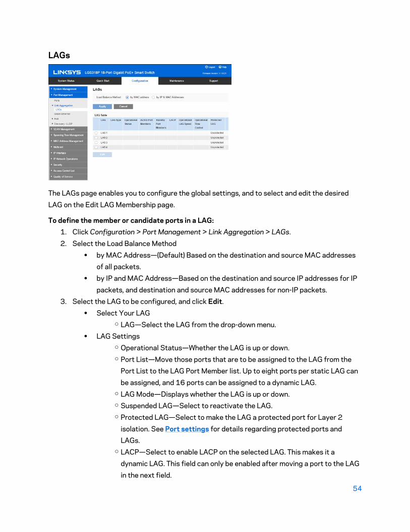
54
LAGs
The LAGs page enables you to configure the global settings, and to select and edit the desired
LAG on the Edit LAG Membership page.
To define the member or candidate ports in a LAG: 1. Click Configuration > Port Management > Link Aggregation > LAGs.
2. Select the Load Balance Method • by MAC Address—(Default) Based on the destination and source MAC addresses
of all packets. • by IP and MAC Address—Based on the destination and source IP addresses for IP
packets, and destination and source MAC addresses for non-IP packets. 3. Select the LAG to be configured, and click Edit.
• Select Your LAG o LAG—Select the LAG from the drop-down menu.
• LAG Settings o Operational Status—Whether the LAG is up or down. o Port List—Move those ports that are to be assigned to the LAG from the
Port List to the LAG Port Member list. Up to eight ports per static LAG can
be assigned, and 16 ports can be assigned to a dynamic LAG. o LAG Mode—Displays whether the LAG is up or down. o Suspended LAG—Select to reactivate the LAG. o Protected LAG—Select to make the LAG a protected port for Layer 2
isolation. See Port settings for details regarding protected ports and LAGs.
o LACP—Select to enable LACP on the selected LAG. This makes it a dynamic LAG. This field can only be enabled after moving a port to the LAG
in the next field.

55
o Auto Negotiation—Select to enable auto-negotiation on the LAG. Auto-
negotiation is a protocol between two link partners that enables a LAG to advertise its transmission speed and flow control to its partner (the Flow
Control default is disabled). It is recommended to keep auto-negotiation
enabled on both sides of an aggregate link, or disabled on both sides, while ensuring that link speeds are identical.
o Port Speed—Configure the speed of the LAG. The port types determine the
available speeds. You can designate this field only when port auto- negotiation is disabled.
o Auto Advertisement—Select the capabilities to be advertised by the LAG. - Max Capability—All LAG speeds and both duplex modes are
available. - 10 Full Duplex—The LAG advertises a 10 Mbps speed and the
mode is full duplex. - 100 Full Duplex—The LAG advertises a 100 Mbps speed and the
mode is full duplex. - 1000 Full Duplex—The LAG advertises a 1000 Mbps speed and
the mode is full duplex. o Flow Control—Set Flow Control to either Enable or Disable or Auto-
Negotiation. o Description—Enter the LAG name or a comment.
4. Click Apply. LAG membership is saved to the Running Configuration file.

56
Green Ethernet
Green Ethernet is a common name for a set of features that is designed to be environmentally
friendly, and to reduce the power consumption of a device. Green Ethernet is different from EEE
in that Green Ethernet energy-detect is enabled on all devices where only the gigabyte ports are enabled with EEE.
The Green Ethernet feature can reduce overall power usage in the following ways. • Short-Reach Mode—Provides for power savings on a short length of cable. After cable
length is analyzed, the power usage is adjusted for various cable lengths. If the cable is
shorter than 50 meters, the device uses less power to send frames over the cable, thus
saving energy. This mode is only supported on RJ45 GE ports; it does not apply to Combo ports. This mode is globally disabled by default. It cannot be enabled if EEE mode is
enabled (see below).
802.3 Energy Efficient Ethernet (EEE)—Reduces power consumption when there is no traffic on
the port. See Energy Efficient Ethernet for more information. EEE is enabled globally by default.
On a given port, if EEE is enabled, short reach mode will be disabled. If Short Reach Mode is
enabled, EEE is grayed out.
These modes are configured per port, without taking into account the LAG membership of the
ports.

57
Power savings, current power consumption and cumulative energy saved can be monitored. The
total amount of saved energy can be viewed as a percentage of the power that would have been consumed by the physical interfaces had they not been running in Green Ethernet mode.
The saved energy displayed is only related to Green Ethernet. The amount of energy saved by
EEE is not displayed.
Energy Efficient Ethernet
EEE is designed to save power when there is no traffic on the link. In Green Ethernet, power is
reduced when the port is down. With EEE, power is reduced when the port is up, but there is no traffic on it.
When using 802.3 EEE, systems on both sides of the link can disable portions of their
functionality and save power during periods of no traffic. 802.3 EEE supports IEEE 802.3 MAC operation at 100 Mbps and 1000 Mbps.
LLDP is used to select the optimal set of parameters for both devices. If LLDP is not supported by
the link partner, or is disabled, 802.3 EEE will still be operational, but it might not be in the optimal operational mode.
The 802.3 EEE feature is implemented using a port mode called Low Power Idle (LPI) mode. When
there is no traffic and this feature is enabled on the port, the port is placed in the LPI mode, which reduces power consumption dramatically.
Both sides of a connection (device port and connecting device) must support 802.3 EEE for it to
work. When traffic is absent, both sides send signals indicating that power is about to be reduced. When signals f s (and not in Down status), and power is reduced.
For ports to stay in LPI mode, the Keep Alive signal must be received continuously from both
sides.
Power Saving by Disabling Port LEDs
Use the Green Ethernet feature to disable port LEDs (link, speed, and PoE) when they are not
needed. Enable them if needed (debugging, connecting additional devices, etc.).
Advertise Capabilities Negotiation
802.3 EEE support is advertised during the Auto-Negotiation stage. Auto-Negotiation provides a
linked device with the capability to detect the abilities (modes of operation) supported by the
device at the other end of the link, determine common abilities, and configure itself for joint operation. Auto-Negotiation is performed at the time of link-up, on command from management,
or upon detection of a link error. During the link establishment process, both link partners
exchange their 802.3 EEE capabilities. Auto- Negotiation functions automatically without user interaction when it is enabled on the device.

58
Note—If Auto-Negotiation is not enabled on a port, the EEE is disabled. The only exception is if the
link speed is 1GB, then EEE will still be enabled even though Auto-Negotiation is disabled.
Default Configuration
By default, 802.3 EEE is enabled globally and per port.
Interactions Between Features
802.3 EEE interactions with other features:
• If auto-negotiation is not enabled on the port, the 802.3 EEE operational status is disabled. The exception to this rule is that if the link speed is 1gigabit, EEE will still be enabled even though Auto-Negotiation is disabled.
• If 802.3 EEE is enabled and the port is going up, it commences to work immediately in accordance with the maximum wake time value of the port.
• On the GUI, the EEE field for the port is not available when the Short Reach Mode option on the port is checked.
• If the port speed on the GE port is changed to 10Mbit, 802.3 EEE is disabled. This is supported in GE models only.
802.3 EEE Configuration Workflow
This section describes how to configure the 802.3 EEE feature and view its counters.
1. Ensure that auto-negotiation is enabled on the port by opening the Ports page.
• Select a port and open the Edit Ports page.
• Select Auto Negotiation field to ensure that it is enabled.
2. Ensure that 802.3 Energy Efficient Ethernet (EEE) is globally enabled in the Green Ethernet page (it is enabled by default). This page also displays how much energy has been saved.
3. Ensure that 802.3 EEE is enabled on a port by opening the Green Ethernet page.
• Select a port, open the Edit Ports page.
• Check the 802.3 Energy Efficient Ethernet (EEE) mode on the port (it is enabled by default).
Configuring Green Ethernet To configure Green Ethernet globally and on a port:
1. Click Configuration > Port Management > Green Ethernet.
• Energy Detect Mode—Select to globally enable. • Port LEDs—Select to disable port LEDs. When disabled, ports do not display link
status, activity, etc. • Short Reach—Select to globally enable Short Reach mode if there are Green
Ethernet ports on the device.

59
Note—If Short Reach is enabled, EEE must be disabled.
• 802.3 Energy Efficient Ethernet (EEE)—Select to globally enable EEE. 2. Click Apply to set the global settings.
• Power Savings—The percentage of power saved by running Green Ethernet and
Short Reach. The power savings displayed is only relevant to the power saved by
Short Reach and Energy Detect modes. The EEE power savings is dynamic by
nature since it is based on port utilization and is therefore not taken into
consideration. The power saving calculation is performed by comparing the
maximum power consumption without power savings to the current consumption. • Cumulative Energy Saved—The amount of energy saved from the last device
reboot in watt hours. This value is updated each time there is an event that affects
power saving.
3. Select a port and click Edit. • Select Your Port
o Port—Select a port from the drop-down menu. • Port Settings
o Energy Detect Mode—Select to enable. o Short Reach Mode—Select to enable. o 802.3 EEE Mode—Select to enable. o EEE LLDP Mode—Select to enable.
• EEE Status—Whether EEE is currently operating on the local port. This is a
function of whether it has been enabled (Administrative Status), whether it has
been enabled on the local port and whether it is operational on the local port.
Note—The Green Ethernet Table displays the Short Reach, Energy Detect and
EEE settings for each port; however, they are not enabled on any port unless they
are also enabled globally.
PoE
A Power over Ethernet (PoE) device is PSE (Power Sourcing Equipment) that delivers electrical power to connected PD (Powered Devices) over existing copper cables without interfering with the network traffic, updating the physical network or modifying the network infrastructure. The PoE feature is only available on PoE-based devices.
60
PoE capabilities:
• Eliminates the need to run 110/220 V AC power to all devices on a wired LAN.
• Removes the necessity for placing all network devices next to power sources.
• Eliminates the need to deploy double cabling systems in an enterprise, significantly decreasing installation costs.
Power over Ethernet can be used in any enterprise network that deploys relatively low-powered devices connected to the Ethernet LAN:
• IP phones
• Wireless access points
• IP gateways
• Audio and video remote monitoring devices
PoE Operation
PoE implementation stages:
• Detection—Sends special pulses on the copper cable. When a PoE device is located at the other end, that device responds to these pulses.
• Classification—Negotiation between the Power Sourcing Equipment (PSE) and the Powered Device (PD) commences after the Detection stage. During negotiation, the PD specifies its class, which is the amount of maximum power that the PD consumes.
• Power Consumption—After the classification stage completes, the PSE provides power to the PD. If the PD supports PoE, but without classification, it is assumed to be class 0 (the maximum). If a PD tries to consume more power than permitted by the standard, the PSE stops supplying power to the port.
Power Modes
Power per port can be limited depending on the Power Mode:
• Port Limit—Power is limited to a specified wattage. For these settings to be active, the system must be in PoE Port Limit mode. That mode is configured in the PoE Feature Configuration page. When the power consumed on the port exceeds the port limit, the port power is turned off.
• Class Limit—Power is limited based on the class of the connected PD. For these settings to be active, the system must be in PoE Class Limit mode. That mode is configured in the PoE Feature Configuration page. When the power consumed on the port exceeds the class limit, the port power is turned off.

61
PoE Priority Example
A 48-port device is supplying a total of 375 watts.
The administrator configures all ports to allocate up to 30 watts each. This results in 48 times 30 ports equaling 1440 watts, which is too much. The device cannot provide enough power to each port, so it provides power according to the priority.The administrator sets the priority for each port, allocating how much power it can be given.
These priorities are entered in the PoE Port Limit Mode or Class Limit Power Mode pages.
PoE Configuration Considerations
There are two factors to consider in PoE configuration:
• The amount of power that the PSE can supply
• The amount of power that the PD is attempting to consume
You can decide the following:
• Maximum power a PSE is allowed to supply to a PD
• POE mode—To change the mode from Class Power Limit to Port Limit, and vice versa, during device operation. The power values per port that were configured for the Port Limit mode are retained.
Note—Changing the mode from Class Limit to Port limit, and vice versa, when the device is operational forces the Powered Device to reboot.
• Maximum port limit allowed as a per-port numerical limit in mW (Port Limit mode).
The PoE-specific hardware automatically detects the PD class and its power limit according to the class of the device connected to each specific port (Class Limit mode).
If at any time during the connectivity an attached PD requires more power from the device than the configured allocation allows (no matter if the device is in Class Limit or Port Limit mode), the device maintains the up/down status of the PoE port link, turns off power delivery to the PoE port, and logs the reason for turning off power.
Caution—Consider the following when connecting switches capable of supplying PoE. o The PoE model of the device is PSE (Power Sourcing Equipment) that is capable of
supplying DC power to attaching PD (Powered Devices). These devices include VoIP phones, IP cameras, and wireless access points.
o Even though the PoE switches are PSE, and as such should be powered by AC, they could be powered up as a legacy PD by another PSE due to false detection. When this happens, the PoE device may not operate properly and may not be able to properly supply power to its attaching PDs.

62
o To prevent false detection, you should disable PoE on the ports on the PoE switches that are used to connect to PSEs. You should also first power up a PSE device before connecting it to a PoE device. When a device is being falsely detected as a PD, you should disconnect the device from the PoE port and power cycle the device with AC power before reconnecting its PoE ports.
Feature Configuration
The Feature Configuration page enables selecting either the Port Limit or Class Limit PoE mode.
These settings are entered in advance. When the PD actually connects and is consuming power, it might consume much less than the maximum power allowed.
Output power is disabled during power-on reboot, initialization, and system configuration to ensure that PDs are not damaged.
To configure PoE on the device and monitor current power usage:
1. Click Configuration > Port Management > PoE > Feature Configuration.
2. Enter values for:
• Power Mode—Select one of the following options:
• Port Limit—The maximum power limit per each port is configured by the user.
• Class Limit—The maximum power limit per port is determined by the class of the device, which results from the Classification stage.
Note—When you change from Port Limit to Class Limit, or vice versa, you must disable PoE ports, and enable them after changing the power configuration.
The following counters are displayed for the device:
• Nominal Power —The total amount of power in watts that the device can supply to all the connected PDs.

63
• Consumed Power—Amount of power in watts that is currently being consumed by the PoE ports.
• Available Power—Nominal power in watts minus the amount of consumed power.
3. Click Apply to save the PoE properties.
Port Limit Power Mode
To configure port limit power mode:
1. Click Configuration > Port Management > PoE > Port Limit Power Mode. The list of fields below is for Port Limit Power Mode.
• PoE Status—Enable or disable PoE on the port.
• Power Priority Level—Port priority is low, high, or critical, for use when the power supply is low. For example, if the power supply is running at 99% usage and port 1 is prioritized as high, but port 3 is prioritized as low, port 1 receives power and port 3 might be denied power.
• Power Allocation Limit (mW)—Power in milliwatts allocated to the port.
• Max Power Allocation (mW)—Maximum amount of power permitted on this port.
• Power Consumption (mW)—Amount of power assigned to the powered device connected to the selected interface.
• Class—Power class of device.
• Operational Status—Displays whether Power Limit mode is enabled or disabled on the port.
2. Select a port and click Edit. Enter the fields as described above.
3. Click Apply. The PoE settings for the port are written to the Running Configuration file.

64
Class Limit Power Mode
To configure class limit power mode:
1. Click Configuration > Port Management > PoE > Class Limit Power Mode.
• PoE Status—Enable or disable PoE on the port.
• Power Priority Level—Port priority is low, high, or critical, for use when the power supply is low. For example, if the power supply is running at 99% usage and port 1 is prioritized as high, but port 3 is prioritized as low, port 1 receives power and port 3 might be denied power.
• Class—Class configured on this port. The classes are shown in the following:
Class Maximum Power Delivered by Device Port
0 15.4 watt
1 4.0 watt
2 7.0 watt
3 15.4 watt
4 30.0 watt
• Max Power Allocation (mW)—Maximum amount of power permitted on this port. The switch hardware may actually supply 5-10% more power than Max Power Allocation to accommodate the power loss over the wire.
• Power Consumption (mW)—Amount of power assigned to the powered device connected to the selected interface.
• Operational Status—Whether the Class Limit mode is enabled or disabled on the port.

65
2. Select a port and click Edit. Enter the fields as described above.
3. Click Apply. The PoE settings for the port are written to the Running Configuration file.
Discovery - LLDP
Link Layer Discovery Protocol (LLDP) is a link layer protocol for directly-connected LLDP-capable neighbors to advertise themselves and their capabilities. LLDP enables network managers to troubleshoot and enhance network management in multi-vendor environments. LLDP standardizes methods for network devices to advertise themselves to other systems, and to store discovered information.
By default, the device sends an LLDP advertisement periodically to all its interfaces and processes incoming LLDP packets as required by the protocols. In LLDP, advertisements are encoded as TLV (Type, Length, Value) in the packet.
The information learned is stored in the data in a Management Information Base (MIB). The network management system models the topology of the network by querying these MIB databases.
By default, the device terminates and processes all incoming LLDP packets as required by the protocol.
The LLDP protocol has an extension called LLDP Media Endpoint Discovery (LLDP-MED) that provides and accepts information from media endpoint devices such as VoIP phones and video phones.
Some notes about LLDP configuration:
• LLDP can be enabled or disabled globally or per port. The LLDP capability of a port is relevant only if LLDP is globally enabled.
• If LLDP is globally enabled, the device filters out incoming LLDP packets from ports that are LLDP-disabled.
• If LLDP is globally disabled, the device can be configured to discard, VLAN- aware flooding, or VLAN-unaware flooding of all incoming LLDP packets. VLAN-aware flooding floods an incoming LLDP packet to the VLAN where the packet is received excluding the ingress port. VLAN-unaware flooding floods an incoming LLDP packet to all the ports excluding the ingress port. The default is to discard LLDP packets when LLDP is globally disabled. You can configure the discard/flooding of incoming LLDP packets from the LLDP Feature Configuration page.
• LLDP end devices, such as IP phones, learn the voice VLAN configuration from LLDP advertisements. By default, the device is enabled to send out LLDP advertisement based on the voice VLAN configured at the device. Refer to the Voice VLAN for details.
Note—LLDP does not distinguish if a port is in a LAG. If there are multiple ports in a LAG, LLDP transmit packets on each port without taking into account the fact that the ports are in a LAG.

66
The operation of LLDP is independent of the STP status of an interface.
If 802.1x port access control is enabled at an interface, the device transmits and receives LLDP packets to and from the interface only if the interface is authenticated and authorized.
If a port is the target of mirroring, then LLDP considers it down.
Note—LLDP are link layer protocols for directly-connected LLDP capable devices to advertise themselves and their capabilities. In deployments where the LLDP-capable devices are not directly connected and are separated with LLDP-incapable devices, the LLDP-capable devices may be able to receive the advertisement from other devices only if the LLDP-incapable devices flood the LLDP packets they receive. If the LLDP-incapable devices perform VLAN-aware flooding, then LLDP-capable devices can hear each other only if they are in the same VLAN. An LLDP-capable device may receive advertisements from more than one device if the LLDP-incapable devices flood the LLDP packets.
Workflows
Following are examples of actions that can be performed with the LLDP feature and in a suggested order. You can refer to the LLDP section for additional guidelines on LLDP configuration. LLDP configuration pages are accessible under the Configuration > Port Management > Discovery - LLDP menu.
1. Enter LLDP global parameters, such as LLDP Frames Handling using the LLDP Feature Configuration page.
2. Configure LLDP per port by using the LLDP Feature Configuration page. On this page, interfaces can be configured to receive/transmit LLDP PDUs, send SNMP notifications, specify which TLVs to advertise, and advertise the device's management address.
3. Create LLDP MED network policies by using the LLDP MED Network Policy page.
4. Associate LLDP MED network policies and the optional LLDP-MED TLVs to the desired interfaces by using the LLDP MED Port Settings page.
Feature Configuration

67
The LLDP-MED TLVs to be advertised can be selected in the LLDP MED Port Settings page, and the management address TLV of the device may be configured to be advertised.
To configure the LLDP port settings:
1. Click Configuration > Port Management > Discovery – LLDP > Feature Configuration.
The following fields are displayed (only fields that do not appear in the Edit page are described):
• Interface—The port to edit.
• LLDP MED Status—Enabled or disabled.
• Number of neighbors—Number of neighbors discovered.
• Neighbor Capability—Displays the primary functions of the neighbor; for example: Bridge or Router.
• Local PoE—Local PoE information advertised. o power priority—Port power priority o power value—Port power value
• Neighbor PoE—PoE information advertised by the neighbor. o power priority—Port power priority o power value—Port power value
2. Enter the following fields.
• LLDP Status—Select to enable LLDP on the device (enabled by default).
• LLDP Frame Handling—If LLDP is not enabled, select the action to be taken if a packet that matches the selected criteria is received:
o Filtering—Delete the packet. o Flooding—Forward the packet to all VLAN members.
3. Select a port and click Edit.
• Port—Select the port to edit.
• LLDP Status—Select the LLDP publishing option for the port. The values are: o Tx Only—Publishes but does not discover. o Rx Only—Discovers but does not publish. o Tx & Rx—Publishes and discovers. o Disable—Indicates that LLDP is disabled on the port.
• Available Optional TLVs—Information to be published by the device.
• Advertise Optional TLVs—Select the information to be published by the device by moving the TLV from the Available Optional TLVs list. The available TLVs contain the following information:
68
o Port Description—Information about the port, including manufacturer, product name and hardware/software version.
o System Name—System's assigned name (in alpha-numeric format). The value equals the sysName object.
o System Description—Description of the network entity (in alpha-numeric format). This includes the system's name and versions of the hardware, operating system, and networking software supported by the device. The value equals the sysDescr object.
o System Capabilities—Primary functions of the device, and whether or not these functions are enabled on the device. The capabilities are indicated by two octets. Bits 0 through 7 indicate Other, Repeater, Bridge, WLAN AP, Router, Telephone, DOCSIS cable device, and station respectively. Bits 8 through 15 are reserved.
o 802.3 MAC-PHY—Duplex and bit rate capability and the current duplex and bit rate settings of the sending device. It also indicates whether the current settings are due to auto-negotiation or manual configuration.
o 802.3 Link Aggregation—Whether the link (associated with the port on which the LLDP PDU is transmitted) can be aggregated. It also indicates whether the link is currently aggregated, and if so, provides the aggregated port identifier.
o 802.3 Maximum Frame—Maximum frame size capability of the MAC/PHY Management Address TLV—Select one of the following ways to advertise the IP management address of the device:
o Auto Advertise—Specifies that the software automatically chooses a management address to advertise from all the IP addresses of the device. In case of multiple IP addresses, the software chooses the lowest IP address among the dynamic IP addresses. If there are no dynamic addresses, the software chooses the lowest IP address among the static IP addresses.
o None—Do not advertise the management IP address. o Manual Advertise—Select this option and the management IP address to
be advertised.
• Management IP Address—If Manual Advertise was selected, select the Management IP address from the addresses provided.
4. Enter the relevant information, and click Apply. The port settings are written to the Running Configuration file.

69
LLDP MED Ports
The LLDP MED Ports page enables the selection of the LLDP MED TLVs and/or the network policies to be included in the outgoing LLDP advertisement for the desired interfaces. Network Policies are configured using the LLDP MED Network Policy page.
To configure LLDP MED on each port:
1. Click Configuration > Port Management > Discovery – LLDP > LLDP MED Ports.
This page displays the following LLDP MED settings for all ports (only fields not described in the Edit page are listed):
• Location—Whether Location TLV is transmitted.
• PoE—Whether POE-PSE TLV is transmitted.
• Inventory—Whether Inventory TLV is transmitted.
2. The message at the top of the page indicates whether the generation of the LLDP MED Network Policy for the voice application is automatic or not. Click on the link to change the mode.
3. To associate additional LLDP MED TLV and/or one or more user-defined LLDP MED Network Policies to a port, select it, and click Edit.
4. Enter the parameters:
• Port—Select the interface to configure.
• LLDP MED Status—Enable/disable LLDP MED on this port.
• Available Optional TLVs—Select the TLVs that can be published by the device by moving them from the Advertise Optional TLVs list.

70
• Available Network Policies—Select the LLDP MED policies to be published by LLDP by moving them from the Available Network Policies list. These were created in the LLDP MED Network Policy page. To include one or more user-defined network polices in the advertisement, you must also select Network Policy from the Available Optional TLVs.
Note—The following fields must be entered in hexadecimal characters in the exact data format that is defined in the LLDP-MED standard (ANSI-TIA-1057_final_for_publication.pdf):
• Location Coordinate—Enter the coordinate location to be published by LLDP. • Location Civic Address—Enter the civic address to be published by LLDP. • Location (ECS) ELIN—Enter the Emergency Call Service (ECS) ELIN location to
be published by LLDP. 5. Click Apply. The LLDP MED port settings are written to the Running Configuration file.
LLDP Local Information

71
To view the LLDP local port status advertised on a port:
1. Click Configuration > Port Management Discovery - LLDP > LLDP Local Information.
2. Select the desired port from the Port list.
This page displays the following groups of fields (the actual fields displayed depend on the optional TLVs selected to be advertised):
• Global o Chassis ID Subtype—Type of chassis ID. (For example, the MAC address.) o Chassis ID—Identifier of chassis. Where the chassis ID subtype is a MAC
address, the MAC address of the device appears. o System Name—Name of device. o System Description—Description of the device (in alpha-numeric format). o Supported System Capabilities—Primary functions of the device, such as
Bridge, WLAN AP, or Router. o Enabled System Capabilities—Primary enabled function(s) of the device. o Port ID Subtype—Type of the port identifier that is shown. o Port ID—Identifier of port. o Port Description—Information about the port, including manufacturer,
product name and hardware/software version.
• Management Address o Displays the table of addresses of the local LLDP agent. Other remote
managers can use this address to obtain information related to the local device. The address consists of the following elements:
o Address Subtype—Type of management IP address that is listed in the o Management Address field; for example, IPv4. o Address—Returned address most appropriate for management use. o Interface Subtype—Numbering method used for defining the interface
number. o Interface Number—Specific interface associated with this management
address.
• MED Information o Capabilities Supported—MED capabilities supported on the port. o Current Capabilities—MED capabilities enabled on the port. o Device Class—LLDP-MED endpoint device class. The possible device
classes are: o Endpoint Class 1—Generic endpoint class, offering basic LLDP services.

72
o Endpoint Class 2—Media endpoint class, offering media streaming capabilities, as well as all Class 1 features.
o Endpoint Class 3—Communications device class, offering all Class 1 and Class 2 features plus location, 911, Layer 2 device support, and device information management capabilities.
o PoE Device Type—Port PoE type; for example, powered. o PoE Power Source—Port power source. o PoE Power Priority—Port power priority. o PoE Power Value—Port power value. o Hardware Revision—Hardware version. o Firmware Revision—Firmware version. o Software Revision—Software version. o Serial Number—Device serial number. o Manufacturer Name—Device manufacturer name. o Model Name—Device model name. o Asset ID—Asset ID.
• Location Information o Civic—Street address. o Coordinates—Map coordinates: latitude, longitude, and altitude. o ECS ELIN—Emergency Call Service (ECS) Emergency Location
Identification Number (ELIN).
• Network Policy o Application Type—Network policy application type; for example, Voice. o VLAN ID—VLAN ID for which the network policy is defined. o VLAN Type—VLAN type for which the network policy is defined. The
possible field values are: - Tagged—Indicates the network policy is defined for tagged VLANs. - Untagged—Indicates the network policy is defined for untagged
VLANs. o User Priority—Network policy user priority. o DSCP—Network policy DSCP.

73
LLDP Neighbor Information
The LLDP Neighbors Information page contains information that was received from neighboring devices. After timeout (based on the value received from the neighbor Time To Live TLV during which no LLDP PDU was received from a neighbor), the information is deleted.
To view the LLDP neighbor information:
Click Configuration>Port Management > Discovery - LLDP > LLDP Neighbor Information.
• Local Port—Number of the local port to which the neighbor is connected
• Global
o Local Port—Port number. (Ron- Gina Please confirm the Global items.) o MSAP Entry—Device Media Service Access Point (MSAP) entry number.
• Basic Details
o Chassis ID Subtype—Type of chassis ID (for example, MAC address). o Chassis ID—Identifier of the 802 LAN neighboring device chassis. o Port ID Subtype—Type of the port identifier that is shown. o Port ID—Identifier of port. o Port Description—Information about the port, including manufacturer, product
name and hardware/software version. o System Name—Name of system that is published. o System Description—Description of the network entity (in alpha-numeric format).
This includes the system name and versions of the hardware, operating system, and networking software supported by the device. The value equals the sysDescr object.

74
o Supported System Capabilities—Primary functions of the device. The capabilities are indicated by two octets. Bits 0 through 7 indicate Other, Repeater, Bridge, WLAN AP, Router, Telephone, DOCSIS cable device, and station, respectively. Bits 8 through 15 are reserved.
o Enabled System Capabilities—Primary enabled function(s) of the device.
• Management Address
o Address Subtype—Managed address subtype; for example, MAC or IPv4. o Address—Managed address. o Interface Subtype—Port subtype. o Interface Number—Port number.
• MED Information
o Capabilities Supported—MED capabilities enabled on the port. o Current Capabilities—MED TLVs advertised by the port. o Device Class—LLDP-MED endpoint device class. The possible device classes are:
- Endpoint Class 1—Indicates a generic endpoint class, offering basic LLDP services.
- Endpoint Class 2—Indicates a media endpoint class, offering media streaming capabilities as well as all Class 1 features.
- Endpoint Class 3—Indicates a communications device class, offering all Class 1 and Class 2 features plus location, 911, Layer 2 switch support and device information management capabilities.
o PoE Device Type—Port PoE type, for example, powered. o PoE Power Source—Port’s power source. o PoE Power Priority—Port’s power priority. o PoE Power Value—Port’s power value. o Hardware Revision –Hardware version. o Firmware Revision—Firmware version. o Software Revision—Software version. o Serial Number—Device serial number. o Manufacturer Name—Device manufacturer name. o Model Name—Device model name. o Asset ID—Asset ID.
• Location Information
Enter the following data structures in hexadecimal as described in section 10.2.4 of the ANSI-TIA-1057 standard:

75
o Civic—Civic or street address. o Coordinates—Location map coordinates—latitude, longitude, and altitude. o ECS ELIN—Device’s Emergency Call Service (ECS) Emergency Location
Identification Number (ELIN). o Unknown—Unknown location information.
• Network Policy
o Application Type—Network policy application type, for example, Voice. o VLAN ID—VLAN ID for which the network policy is defined. o VLAN Type—VLAN type, Tagged or Untagged, for which the network policy is
defined. o User Priority—Network policy user priority. o DSCP—Network policy DSCP.
LLDP MED Network Policy
LLDP Media Endpoint Discovery (LLDP-MED) is an extension of LLDP that provides the following additional capabilities to support media endpoint devices:
• Enables the advertisement and discovery of network polices for real-time applications such as voice and/or video.
• Enables discovery of the device location to allow creation of location databases and, in the case of Voice over Internet Protocol (VoIP), Emergency Call Service (E-911) by using IP Phone location information.
• Troubleshooting information. LLDP MED sends alerts to network managers upon: o Port speed and duplex mode conflicts o QoS policy misconfigurations

76
Setting LLDP MED Network Policy
An LLDP-MED network policy is a related set of configuration settings for a specific real-time application such as voice, or video. A network policy, if configured, can be included in the outgoing LLDP packets to the attached LLDP media endpoint device. The media endpoint device must send its traffic as specified in the network policy it receives. For example, a policy can be created for VoIP traffic that instructs VoIP phone to:
• Send voice traffic on VLAN 10 as tagged packet and with 802.1p priority 5.
• Send voice traffic with DSCP 46.
Network policies are associated with ports by using the LLDP MED Port Settings page. An administrator can manually configure one or more network policies and the interfaces where the policies are to be sent. It is the administrator's responsibility to manually create the VLANs and their port memberships according to the network policies and their associated interfaces.
In addition, an administrator can instruct the device to automatically generate and advertise a network policy for voice application based on the voice VLAN maintained by the device. Refer the Auto Voice VLAN section for details on how the device maintains its voice VLAN.
To define an LLDP MED network policy:
1. Click Configuration > Port Management > Discovery – LLDP > LLDP MED Network.
This page contains previously-created network policies.
2. When Network Policy for Voice Application is enabled, the device automatically generates and advertises a network policy with the current voice VLAN configuration. Go to Voice VLAN > Feature Configuration page to configure the voice VLAN.
3. Click Apply to add this setting to the Running Configuration file.
4. To define a new policy, click Add.
5. Enter the values:
• Network Policy Number—Select the number of the policy to be created.
• Application—Select the type of application (type of traffic) for which the network policy is being defined.
• VLAN ID—Enter the VLAN ID to which the traffic must be sent.
• VLAN Tag—Select whether the traffic is Tagged or Untagged.
• Layer 2 Priority—Select the traffic priority applied to traffic defined by this network policy. This is the CoS value.
• DSCP Value—Select the DSCP value to associate with application data sent by neighbors. This informs them how they must mark the application traffic they send to the device.
6. Click Apply. The network policy is defined.
Note—You must manually configure the interfaces to include the desired manually-defined network policies for the outgoing LLDP packets using the LLDP MED Port Settings.

77
Chapter 6 – VLAN Management
VLANs
A VLAN is a logical group of ports that enables devices associated with it to communicate with each other over the Ethernet MAC layer, regardless of the physical LAN segment of the bridged network to which they are connected.
Each VLAN is configured with a unique VLAN ID (VID) with a value from 1 to 4094. A port on a device in a bridged network is a member of a VLAN if it can send data to and receive data from the VLAN. A port is an untagged member of a VLAN if all packets destined for that port into the VLAN have no VLAN tag. A port is a tagged member of a VLAN if all packets destined for that port into the VLAN have a VLAN tag. A port can be a member of only one untagged VLAN but can be a member of multiple tagged VLANs.
A port in VLAN Access mode can be part of only one VLAN. If it is in General or Trunk mode, the port can be part of one or more VLANs.
VLANs address security and scalability issues. Traffic from a VLAN stays within the VLAN, and terminates at devices in the VLAN. It also eases network configuration by logically connecting devices without physically relocating those devices.
If a frame is VLAN-tagged, a four-byte VLAN tag is added to each Ethernet frame. The tag
contains a VLAN ID between 1 and 4094, and a VLAN Priority Tag (VPT) between 0 and 7. See
QoS Operation for details about VPT.
When a frame enters a VLAN-aware device, it is classified as belonging to a VLAN, based on the four-byte VLAN tag in the frame.
If there is no VLAN tag in the frame or the frame is priority-tagged only, the frame is classified to the VLAN based on the PVID (Port VLAN Identifier) configured at the ingress port where the frame is received.

78
The frame is discarded at the ingress port if Ingress Filtering is enabled and the ingress port is not a member of the VLAN to which the packet belongs. A frame is regarded as priority-tagged only if the VID in its VLAN tag is 0.
Frames belonging to a VLAN remain within the VLAN. This is achieved by sending or forwarding a frame only to egress ports that are members of the target VLAN. An egress port may be a tagged or untagged member of a VLAN.
The egress port:
• Adds a VLAN tag to the frame if the egress port is a tagged member of the target VLAN, and the original frame does not have a VLAN tag.
• Removes the VLAN tag from the frame if the egress port is an untagged member of the target VLAN, and the original frame has a VLAN tag.
VLAN Roles
All VLAN traffic (Unicast/Broadcast/Multicast) remains within its VLAN. Devices attached to different VLANs do not have direct connectivity to each other over the Ethernet MAC layer.
Device VLANs can only be created statically. Some VLANs can have additional roles, including:
• Voice VLAN: For more information refer to the Voice VLAN section.
• Guest VLAN: Set in the Edit VLAN Authentication page.
• Default VLAN: For more information refer to the Configuring Default VLAN Settings section.
• Management VLAN: For more information refer to the Configuring IP Information section.
VLAN Configuration
To configure VLANs:
1. If required, change the default VLAN as described in the Default VLAN Settings section.
2. Create the required VLANs as described in the VLANs - Creating VLANs section.
3. Set the desired VLAN-related configuration for ports, as described in the Interface Settings section.
4. Assign interfaces to VLANs as described in the Port to VLAN section or the VLAN Memberships section.
5. View the current VLAN port membership for all the interfaces as described in the VLAN Memberships section.
6. If required, configure VLAN groups as described in the MAC-based Groups section.
79
Default VLAN Settings
When using factory default settings, the device automatically creates VLAN 1 as the default VLAN, the default interface status of all ports is Trunk, and all ports are configured as untagged members of the default VLAN.
The default VLAN has the following characteristics:
• It is distinct, non-static/non-dynamic, and all ports are untagged members by default.
• It cannot be deleted.
• It cannot be given a label.
• It cannot be used for any special role, such as unauthenticated VLAN or Voice VLAN. This is only relevant for OUI-enabled voice VLAN.
• If a port is no longer a member of any VLAN, the device automatically configures the port as an untagged member of the default VLAN. A port is no longer a member of a VLAN if the VLAN is deleted or the port is removed from the VLAN.
When the VID of the default VLAN is changed, the device performs the following on all the ports in the VLAN, after saving the configuration and rebooting the device:
• Removes VLAN membership of the ports from the original default VLAN (takes effect after reboot).
• Changes the PVID (Port VLAN Identifier) of the ports to the VID of the new default VLAN.
• The original default VLAN ID is removed from the device. To be used, it must be recreated.
• Adds the ports as untagged VLAN members of the new default VLAN.
To change the default VLAN:
1. Click Configuration > VLAN Management > VLANs.
2. Enter the value for the following field:
• Current Default VLAN ID—Displays the current default VLAN ID.
• Default VLAN ID After Reboot—Enter a new VLAN ID to replace the default VLAN ID after reboot.
3. Click Apply.
4. Click Save and save the Running Configuration to the Startup Configuration.
The Default VLAN ID After Reset becomes the Current Default VLAN ID after you reboot the device.
Creating VLANs
You can create a VLAN, but this has no effect until the VLAN is attached to at least one port, either manually or dynamically. Ports must always belong to one or more VLANs.

80
The Smart device supports up to 128 VLANs, including the default VLAN. Each VLAN must be configured with a unique VID with a value from 1 to 4094. The device reserves VID 4095 as the Discard VLAN and VID 4094 for 802.1x. All packets classified to the Discard VLAN are discarded at ingress, and are not forwarded to a port. The VLANs page enables you to change the default VLAN and create a new VLAN.
To change or add a VLAN:
1. Click Configuration > VLAN Management > VLANs.
2. Click Add to add one or more new VLANs.
The page enables the creation of either a single VLAN or a range of VLANs.
3. Enter the following fields for the new VLANs.
• VLAN—Select one of the following options: - Single VLAN—Select to create a single VLAN. - Range of VLANs—Select to create a range of VLANs and specify the range
of VLANs to be created by entering the Starting VID and Ending VID, inclusive. When using the Range function, the maximum number of VLANs you can create at one time is 100.
• VLAN ID—Enter a VLAN ID.
• VLAN Name—Enter a VLAN name.
• VLAN ID Range—Enter a range of VLANs.
4. Click Apply to create the VLAN(s).

81
Interfaces
The Interface Settings page displays and enables configuration of VLAN-related parameters for all interfaces.
To configure the interface settings:
1. Click VLAN Management > Interface Settings.
2. Select an interface type (Port or LAG), and click Search. Ports or LAGs and their VLAN Membership are displayed.
3. To configure a Port or LAG, select it and click Edit.
Note—To add a port or LAG to a VLAN, click Join VLAN. The Join VLAN page is displayed.
4. Enter the values for the following fields:
• Interface—Select a Port/LAG.
• Interface VLAN Mode—Select the interface mode for the VLAN. The options are: - Access—The interface is an untagged member of a single VLAN. A port
configured in this mode is known as an access port. - Trunk—The interface is an untagged member of one VLAN at most, and is a
tagged member of zero or more VLANs. A port configured in this mode is known as a trunk port.
- General Port—The interface can support all functions as defined in the IEEE 802.1q specification. The interface can be a tagged or untagged member of one or more VLANs.
82
• PVID—Enter the Port VLAN ID (PVID) of the VLAN to which incoming untagged and priority tagged frames are classified. The possible values are 1 to 4094.
• Acceptable Frame Type—Select the type of frame that the interface can receive. Frames that are not of the configured frame type are discarded at ingress. These frame types are only available in General mode. Possible values are:
- Admit All—The interface accepts all types of frames: untagged frames, tagged frames, and priority tagged frames.
- Admit Tagged Only—The interface accepts only tagged frames. - Admit Untagged Only—The interface accepts only untagged and priority
frames.
• Ingress Filtering—(Available only in General mode) Select to enable ingress filtering. When an interface is ingress filtering enabled, the interface discards all incoming frames that are classified as VLANs of which the interface is not a member. Ingress filtering can be disabled or enabled on general ports. It is always enabled on access ports and trunk ports.
5. Click Apply. The parameters are written to the Running Configuration file.
Join VLAN
When a port is forbidden default VLAN membership, that port is not allowed membership in any other VLAN. An internal VID of 4095 is assigned to the port.
To forward packets properly, intermediate VLAN-aware devices that carry VLAN traffic along the path between end nodes must be manually configured.
Untagged port membership between two VLAN-aware devices with no intervening VLAN-aware devices, must be to the same VLAN. In other words, the PVID on the ports between the two devices must be the same if the ports are to send and receive untagged packets to and from the VLAN. Otherwise, traffic might leak from one VLAN to another.
Frames that are VLAN-tagged can pass through other network devices that are VLAN-aware or VLAN-unaware. If a destination end node is VLAN-unaware, but is to receive traffic from a VLAN, then the last VLAN-aware device (if there is one), must send frames of the destination VLAN to the end node untagged.
To add a port to a VLAN:
1. Click VLAN Management > Interface Settings.
2. Select an interface type (Port or LAG), and click Search.
3. To add a Port or LAG to a VLAN, select it and click Join VLAN.

83
4. Enter the following fields:
• VLAN Mode - Access—The interface is an untagged member of a single VLAN. A port
configured in this mode is known as an access port. - Trunk—The interface is an untagged member of one VLAN at most, and is a
tagged member of zero or more VLANs. A port configured in this mode is known as a trunk port.
- General Port—The interface can support all functions as defined in the IEEE 802.1q specification. The interface can be a tagged or untagged member of one or more VLANs.
• Tagging - Forbidden—The interface is not allowed to join the VLAN. When a port is
not a member of any other VLAN, enabling this option on the port makes the port part of internal VLAN 4095 (a reserved VID).
- Excluded—The interface is currently not a member of the VLAN. This is the default for all the ports and LAGs when the VLAN is newly created.
- Tagged—The interface is a tagged member of the VLAN. - Untagged—The interface is an untagged member of the VLAN. Frames of
the VLAN are sent untagged to the interface VLAN. - PVID—Port PVID is set to this VLAN. If the interface is in access mode or
trunk mode, the device automatically makes the interface an untagged member of the VLAN. If the interface is in general mode, you must manually configure VLAN membership.
5. Click Apply. The port is added to the VLAN and the settings are written to the Running Configuration file.

84
VLAN Memberships
The VLAN Memberships page displays the VLAN memberships of the ports in various presentations. You can use them to add memberships to or remove memberships from the VLANs.
When a port is forbidden default VLAN membership, that port is not allowed membership in any other VLAN. An internal VID of 4095 is assigned to the port.
To forward packets properly, intermediate VLAN-aware devices that carry VLAN traffic along the path between end nodes must be manually configured.
Untagged port membership between two VLAN-aware devices with no intervening VLAN-aware devices, must be to the same VLAN. In other words, the PVID on the ports between the two devices must be the same if the ports are to send and receive untagged packets to and from the VLAN. Otherwise, traffic might leak from one VLAN to another.
Frames that are VLAN-tagged can pass through other network devices that are VLAN-aware or VLAN-unaware. If a destination end node is VLAN-unaware, but is to receive traffic from a VLAN, then the last VLAN-aware device (if there is one), must send frames of the destination VLAN to the end node untagged.
Use the VLAN Memberships page to display and configure the ports within a specific VLAN.
To assign a port to one or more VLANs:
1. Click Configuration > VLAN Management > VLAN Memberships.
2. Select VLAN ID and interface type (Port or LAG), and click Search.

85
• Interface—Port/LAG ID.
• PVID—Port PVID is set to this VLAN. If the interface is in access mode or trunk mode, the device automatically makes the interface an untagged member of the VLAN. If the interface is in general mode, you must manually configure VLAN membership.
• Access—Select to make the interface an access interface on this VLAN.
• Trunk—Select to make the interface a trunk interface on this VLAN.
• General Port—The interface can support all functions as defined in the IEEE 802.1q specification. The interface can be a tagged or untagged member of one or more VLANs.
• Forbidden—The interface is not allowed to join the VLAN. When a port is not a member of any other VLAN, enabling this option on the port makes the port part of internal VLAN 4095 (a reserved VID).
• Excluded—The interface is currently not a member of the VLAN. This is the default for all the ports and LAGs when the VLAN is newly created.
• Tagged—The interface is a tagged member of the VLAN. This is not relevant for Access ports.
• Untagged—The interface is an untagged member of the VLAN. Frames of the VLAN are sent untagged to the interface VLAN. This is not relevant for Access ports.
3. Click Apply. The settings are modified and written to the Running Configuration file.
VLAN Groups
This section describes how to configure Mac-based VLAN groups.
VLAN groups classify packets into VLANs based on their MAC addresses.
VLAN groups can be used to separate traffic into different VLANs for security and/or load balancing.
If several classifications schemes are defined, packets are assigned to a VLAN in the following order:
• TAG—If the packet is tagged, the VLAN is taken from the tag.
• MAC-Based VLAN—If a MAC-based VLAN has been defined, the VLAN is taken from the source MAC-to-VLAN mapping of the ingress interface.
• PVID—VLAN is taken from the port default VLAN ID.

86
MAC-Based Group
MAC-based VLAN classification enables packets to be classified according to their source MAC address. You can then define MAC-to-VLAN mapping per interface.
You can define several MAC-based groups, which each group containing different MAC addresses.
These MAC-based groups can be assigned to specific ports/LAGs. MAC-based groups cannot contain overlapping ranges of MAC addresses on the same port.
The following table describes the availability of MAC-based groups in various SKUs:
Table 1 MAC-Based Group Availability
SKU System Mode MAC-Based Groups
S d Smart Layer 2 Yes
Layer 3 No
Managed Layer 2 Yes
Layer 3 No
To define a MAC-based group:
1. Assign a MAC address to a VLAN group ID (using the MAC-Based Groups page).
2. For each required interface:
• Assign the VLAN group to a VLAN (using the Mac-Based VLAN page). The interfaces must be in General mode.
• If the interface does not belong to the VLAN, manually assign it to the VLAN using the VLAN Membership page.

87
To assign a MAC address to a VLAN Group:
1. Click Configuration > VLAN Management > MAC-Based Group.
2. Click Add.
3. Enter the values for the following fields:
• Group ID—Enter a user-created VLAN group ID number.
• MAC Address—Enter a MAC address to be assigned to a VLAN group.
Note—This MAC address cannot be assigned to any other VLAN group.
• Prefix Mask—Enter one of the following: - Host—Source host of the MAC address - Length—Prefix of the MAC address
4. Click Apply. The MAC address is assigned to a VLAN group.
MAC-Based VLAN per interface
See Table 1 for a description of the availability of this feature. Ports/LAGs must be in General mode.
To assign a MAC-based VLAN group to a VLAN on an interface:
1. Click Configuration > VLAN Management > MAC-Based VLAN.
2. Click Add.
3. Enter the values for the following fields:
• Interface—Enter a general interface (port/LAG) through which traffic is received.
• Group ID—Select a VLAN group, defined in the MAC-Based Groups page.
• VLAN ID—Select the VLAN to which traffic from the VLAN group is forwarded.

88
4. Click Apply to set the mapping of the VLAN group to the VLAN. This mapping does not bind the interface dynamically to the VLAN; the interface must be manually added to the VLAN.)
Voice VLAN
In a LAN, voice devices, such as IP phones, VoIP endpoints, and voice systems are placed into the same VLAN. This VLAN is referred as the voice VLAN. If the voice devices are in different voice VLANs, IP (Layer 3) routers are needed to provide communication.
Auto Voice VLAN
The device supports the Telephony OUI (Organization Unique Identifier) voice VLAN mode. The two modes affect how voice VLAN and/or voice VLAN port memberships are configured.
In Telephony OUI mode, the voice VLAN must be a manually-configured VLAN, and cannot be the default VLAN.
When the device is in Telephony OUI mode and a port is manually configured as a candidate to join the voice VLAN, the device dynamically adds the port to the voice VLAN if it receives a packet with a source MAC address matching one of the configured telephony OUIs. An OUI is the first three bytes of an Ethernet MAC address. For more information about Telephony OUI, see Telephony OUI Interfaces.
Voice End-Points
To have a voice VLAN work properly, the voice devices, such as IP phones and VoIP endpoints, must be assigned to the voice VLAN where it sends and receives its voice traffic.
Two possible scenarios:
• A phone/endpoint may be statically configured with the voice VLAN.
• A phone/endpoint may obtain the voice VLAN in the boot file it downloads from a TFTP server. A DHCP server may specify the boot file and the TFTP server when it assigns an IP address to the phone.
You can create a network policy manually or enable the device to automatically generate a network policy, based on a voice VLAN configuration.
The device expects the attaching voice devices to send voice VLAN, tagged packets. On ports where the voice VLAN is the native VLAN or that is configured with auto voice VLAN by Telephony OUI, voice VLAN untagged packets are possible.

89
Voice VLAN CoS
The device can advertise the CoS/802.1p and DSCP settings of the voice VLAN by using LLDP-MED Network policies. You can create your network policy manually or enable the device to automatically generate the network policy based on your voice VLAN configuration. MED-supported devices must send their voice traffic with the same CoS/802.1p and DSCP values, as received with the LLDP- MED response.
You can disable the automatic update between Voice VLAN and LLDP-MED and use his own network policies.
Working with the OUI mode, the device can additionally configure the mapping and remarking (CoS/802.1p) of the voice traffic based on the OUI.
By default, all interfaces are CoS/802.1p trusted. The device applies the quality of service based on the CoS/802.1p value found in the voice stream.
For Telephony OUI voice streams, you can override the class of service and optionally remark the 802.1p of the voice streams by specifying the desired CoS/802.1p values and using the remarking option under Telephony OUI.
Voice VLAN Constraints
The following constraints exist:
• Only one Voice VLAN is supported.
• A VLAN that is defined as a Voice VLAN cannot be removed.
In addition the following constraints are applicable for Telephony OUI:
• The Voice VLAN cannot be VLAN1 (the default VLAN).
• The Voice VLAN QoS decision has priority over any other QoS decision, except for the Policy decision.
• A new VLAN ID can be configured for the Voice VLAN only if the current Voice VLAN does not have candidate ports.
• The interface VLAN of a candidate port must be in General or Trunk mode.
• The Voice VLAN QoS is applied to candidate ports that have joined the Voice VLAN, and to static ports.
• The voice flow is accepted if the MAC address can be learned by the Forwarding Database (FDB). (If there is no free space in FDB, no action occurs).

90
Feature Configuration
To configure Auto Voice VLAN:
1. Click Configuration > VLAN Management > Voice VLAN > Feature Configuration.
2. Enter the following to configure Voice VLAN:
• Voice VLAN ID—Enter the identifier of the current voice VLAN
• CoS/802.1p—Select the CoS/802.1p value to be used by the LLDP-MED as a voice network policy.
3. Enter the following to configure telephone OUI voice VLAN:
• Telephone OUI Voice VLAN—Check to enable automatically adding ports to voice VLAN when OUI packets are received.
• Remark CoS/802.1p—Select the enable remarking packets with the CoS/802.1p value.
• Aging Time—Enter the time delay to remove a port from the voice VLAN after all of the MAC addresses of the phones detected on the ports have aged out.
4. Click Apply to save the settings to the Running Configuration file.
Refer to Administration > Discovery > LLDP > LLDP MED Network Policy to enable automatic generation of network policy for voice.
To view or add a new OUI:
1. Click Configuration > VLAN Management > Voice VLAN > Feature Configuration.
2. Click Add to add a new OUI.

91
3. Enter the values for the following fields:
• Telephony OUI—First six digits of the MAC address that are reserved for OUIs.
• Description—User-assigned OUI description.
Note—Click Restore to delete all of the user-created OUIs, and leave only the default OUIs in the table. The OUI information may not be accurate until the restoration is
completed. This may take several seconds. After several seconds have passed, refresh
the page by exiting it and re-entering it.
To delete all the OUIs, select the top checkbox. All the OUIs are selected and can be deleted by clicking Delete. If you then click Restore, the system recovers the known OUIs.
4. Click Apply. The OUI is added to the Telephony OUI Table.
Telephony OUI Interfaces
QoS attributes can be assigned per port to the voice packets in one of two modes:
• All—Quality of Service (QoS) values configured to the Voice VLAN are applied to all of the incoming frames that are received on the interface and are classified to the Voice VLAN.
• Telephony Source MAC Address (SRC)—The QoS values configured for the Voice VLAN are applied to any incoming frame that is classified to the Voice VLAN and contains an OUI in the source MAC address that matches a configured telephony OUI.
Use the Telephony OUI Interface page to add an interface to the voice VLAN on the basis of the OUI identifier and to configure the OUI QoS mode of voice VLAN.

92
To configure Telephony OUI on an interface:
1. Click Configuration > VLAN Management > Voice VLAN > Telephony OUI Interfaces.
2. To configure an interface to be a candidate port of the telephony OUI-based voice VLAN, click Edit.
3. Enter the values for the following fields:
• Interface—Select an interface.
• Telephony OUI VLAN—If enabled, the interface is a candidate port of the telephony OUI based voice VLAN. When packets that match one of the configured telephony OUI are received, the port is added to the voice VLAN.
• QoS Mode—Select one of the following options: o All—QoS attributes are applied on all packets that are classified to the
Voice VLAN. o Telephony Source MAC Address—QoS attributes are applied only on
packets from IP phones.
4. Click Apply.

93
Chapter 7 - Spanning Tree Management Spanning Tree Protocol protects a Layer 2 Broadcast domain from Broadcast storms by selectively setting links to standby mode to prevent loops. In standby mode, these links temporarily stop transferring user data. After the topology changes so that the data transfer is made possible, the links are automatically reactivated.
Loops occur when alternate routes exist between hosts. Loops in an extended network can cause switches to forward traffic indefinitely, resulting in increased traffic load and reduced network efficiency.
STP provides a tree topology for any arrangement of switches and interconnecting links, by creating a unique path between end stations on a network, and thereby eliminating loops.
Spanning Tree Protocol versions:
• Classic STP – Provides a single path between any two end stations, avoiding and eliminating loops.
• Rapid STP (RSTP) – Detects network topologies to provide faster convergence of the spanning tree. This is most effective when the network topology is naturally tree-structured, and therefore faster convergence might be possible. RSTP is enabled by default.
• Multiple STP (MSTP) – Classic STP and Rapid STP detect Layer 2 loops, and attempt to mitigate them by preventing the involved port from transmitting traffic. Since loops exist on a per-Layer 2-domain basis, there can be a loop in VLAN A and no loop in VLAN B. If both VLANs are on Port X, Classic STP and Rapid STP will mitigate the loop by stopping traffic on the entire port, including VLAN B traffic.
MSTP solves this problem by enabling several STP instances, so that it is possible to detect and mitigate loops separately in each instance. By associating instances to VLANs, each instance is associated with the Layer 2 domain on which it performs loop detection and mitigation. This enables a port to be stopped in one instance, such as traffic from VLAN A that is causing a loop, while traffic can remain active in another domain where no loop was seen, such as on VLAN B.

94
Spanning Tree
To set the STP status and global settings:
1. Click Configuration > Spanning Tree Management > Spanning Tree.
2. Enter the parameters.
Global Settings:
• Spanning Tree—Select to enable on the device.
• Spanning Tree Mode—Select an STP mode - Classic STP, Rapid STP or Multiple STP.
• Path Cost Default Values—Selects the method used to assign default path costs to the STP ports. The default path cost assigned to an interface varies according to the selected method.
o Short—Specifies the range 1 through 65,535 for port path costs. o Long—Specifies the range 1 through 200,000,000 for port path costs.
• BPDU Handling—Select how Bridge Protocol Data Unit (BPDU) packets are managed when STP is disabled on the port or the device. BPDUs are used to transmit spanning tree information.
o Filtering—Filters BPDU packets when Spanning Tree is disabled on an interface.
o Flooding—Floods BPDU packets when Spanning Tree is disabled on an interface.

95
Bridge Settings:
• Priority—Sets the bridge priority value. After exchanging BPDUs, the device with the lowest priority becomes the Root Bridge. In the case that all bridges use the same priority, then their MAC addresses are used to determine the Root Bridge. The bridge priority value is provided in increments of 4096. For example, 4096, 8192, 12288, and so on.
• Hello Time—Set the interval (in seconds) that a Root Bridge waits between configuration messages.
• Max Age—Set the interval (in seconds) that the device can wait without receiving a configuration message, before attempting to redefine its own configuration.
• Forward Delay—Set the interval (in seconds) that a bridge remains in a learning state before forwarding packet.
Designated Root:
• Bridge ID—The bridge priority concatenated with the MAC address of the device.
• Root Bridge ID—The Root Bridge priority concatenated with the MAC address of the Root Bridge.
• Root Port—The port that offers the lowest cost path from this bridge to the Root Bridge. (This is significant when the bridge is not the root.)
• Root Path Cost—The cost of the path from this bridge to the root.
• Topology Changes Counts—The total number of STP topology changes that have occurred.
• Last Topology Change—The time interval that elapsed since the last topology change occurred. The time appears in a days/hours/minutes/seconds format.
3. Click Apply. The STP Global settings are written to the Running Configuration file.
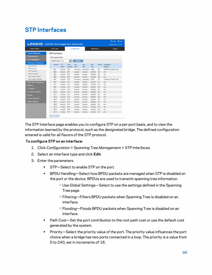
96
STP Interfaces
The STP Interface page enables you to configure STP on a per-port basis, and to view the information learned by the protocol, such as the designated bridge. The defined configuration entered is valid for all flavors of the STP protocol.
To configure STP on an interface:
1. Click Configuration > Spanning Tree Management > STP Interfaces.
2. Select an interface type and click Edit.
3. Enter the parameters.
• STP—Select to enable STP on the port.
• BPDU Handling—Select how BPDU packets are managed when STP is disabled on the port or the device. BPDUs are used to transmit spanning tree information.
o Use Global Settings—Select to use the settings defined in the Spanning Tree page.
o Filtering—Filters BPDU packets when Spanning Tree is disabled on an interface.
o Flooding—Floods BPDU packets when Spanning Tree is disabled on an interface.
• Path Cost—Set the port contribution to the root path cost or use the default cost generated by the system.
• Priority—Select the priority value of the port. The priority value influences the port choice when a bridge has two ports connected in a loop. The priority is a value from 0 to 240, set in increments of 16.

97
• Port State—Displays the current STP state of a port. o Disabled—STP is currently disabled on the port. The port forwards traffic
while learning MAC addresses. o Blocking—The port is currently blocked, and cannot forward traffic (with
the exception of BPDU data) or learn MAC addresses. o Listening—The port is in Listening Mode. The port cannot forward traffic,
and cannot learn MAC addresses. o Learning—The port is in Learning Mode. The port cannot forward traffic,
but it can learn new MAC addresses. o Forwarding—The port is in Forwarding Mode. The port can forward traffic
and learn new MAC addresses.
• Designated Bridge ID—Displays the priority and interface of the selected port.
• Designated Port ID—Displays the priority and interface of the selected port.
• Designated Cost—Displays the cost of the port participating in the STP topology. Ports with a lower cost are less likely to be blocked if STP detects loops.
4. Click Apply. The interface settings are written to the Running Configuration file.
RSTP Interfaces
Rapid Spanning Tree Protocol (RSTP) enables a faster STP convergence without creating forwarding loops.
The RSTP Interface Settings page enables you to configure RSTP per port. Any configuration that is done on this page is active when the global STP mode is set to RSTP or MSTP.

98
To configure RSTPs:
1. Click Configuration > Spanning Tree Management > Spanning Tree.
2. Select Rapid STP on the Spanning Tree Mode line.
3. Click Configuration > Spanning Tree Management > Spanning Tree > RSTP Interfaces.
4. Select an interface, and click Edit.
5. Enter the interface settings:
• Point to Point Mode - Define the point-to-point link status. Ports defined as full duplex are considered point-to-point port links.
o Enable - This port is an RSTP edge port when this feature is enabled, and is brought to Forwarding Mode quickly (usually within 2 seconds).
o Disable - The port is not considered point-to-point for RSTP purposes, which means that STP works on it at regular speed, as opposed to high speed.
o Auto - Automatically determines the device status by using RSTP BPDUs
• Edge Port Mode - Enables or disables Fast Link on the port. If Fast Link Mode is enabled on a port, the port is automatically set to forwarding state when the port link is up. Fast Link optimizes the STP protocol convergence.
The options: o Enable - Enables Fast Link immediately. o Disable - Disables Fast Link. o Auto - Enables Fast Link a few seconds after the interface becomes active.
This allows STP to resolve loops before enabling Fast Link.
Note—It is recommended to set the value to Auto so that the device sets the port to fast link mode if a host is connected to it, or sets it as a regular STP port if connected to another device. This helps avoid loops.
• STP Mode - Select either STP or RSTP.
• Point to Point Status-Displays the point-to-point operational status if the Point to Point Administrative Status is set to Auto.
• Port Role - Displays the role of the port that was assigned by STP to provide STP paths. Possible roles:
o Root - Lowest cost path to forward packets to the root bridge. o Designated - The interface through which the bridge is connected to the
LAN, which provides the lowest cost path from the LAN to the root bridge. o Alternate - Provides an alternate path to the root bridge from the root
interface.
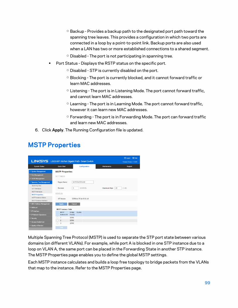
99
o Backup - Provides a backup path to the designated port path toward the spanning tree leaves. This provides a configuration in which two ports are connected in a loop by a point-to-point link. Backup ports are also used when a LAN has two or more established connections to a shared segment.
o Disabled - The port is not participating in spanning tree.
• Port Status - Displays the RSTP status on the specific port. o Disabled - STP is currently disabled on the port. o Blocking - The port is currently blocked, and it cannot forward traffic or
learn MAC addresses. o Listening - The port is in Listening Mode. The port cannot forward traffic,
and cannot learn MAC addresses. o Learning - The port is in Learning Mode. The port cannot forward traffic,
however it can learn new MAC addresses. o Forwarding - The port is in Forwarding Mode. The port can forward traffic
and learn new MAC addresses.
6. Click Apply. The Running Configuration file is updated.
MSTP Properties
Multiple Spanning Tree Protocol (MSTP) is used to separate the STP port state between various domains (on different VLANs). For example, while port A is blocked in one STP instance due to a loop on VLAN A, the same port can be placed in the Forwarding State in another STP instance. The MSTP Properties page enables you to define the global MSTP settings.
Each MSTP instance calculates and builds a loop free topology to bridge packets from the VLANs that map to the instance. Refer to the MSTP Properties page.

100
Decide which MSTP instance be active in what VLAN, and associate these MSTP instances to VLAN(s) accordingly.
Configure MSTP attributes on the following pages:
• MSTP Properties
• MSTP Instance Status
• MSTP Instance Interface
MSTP Interfaces
The global MSTP configures a separate Spanning Tree for each VLAN group and blocks all but one of the possible alternate paths within each spanning tree instance. MSTP enables formation of MST regions that can run multiple MST instances (MSTI). Multiple regions and other STP bridges are interconnected using one single common spanning tree (CST).
MSTP is fully compatible with RSTP bridges, in that an MSTP BPDU can be interpreted by an RSTP bridge as an RSTP BPDU. This not only enables compatibility with RSTP bridges without configuration changes, but also causes any RSTP bridges outside of an MSTP region to see the region as a single RSTP bridge, regardless of the number of MSTP bridges inside the region itself.
Up to three MST instances (predefined from 1-3) can be defined on Smart switches, in addition to instance zero.
VLAN to MSTP Instance Mapping
For two or more switches to be in the same MST region, they must have the same VLANs to MST instance mapping, the same configuration revision number, and the same region name. Switches intended to be in the same MST region are never separated by switches from another MST region. If they are separated, the region becomes two separate regions.
The VLAN to MSTP instance mapping is done in the MSTP Properties page. Each VLAN can be mapped to a MSTP instance. For devices to be in the same region, they must have the same mapping of VLANs to MSTP instances.
Configuration on this page (and all of the MSTP pages) applies if the system STP mode is MSTP.
Note—The same MSTI can be mapped to more than one VLAN, but each VLAN can only have one MST Instance attached to it.
For those VLANs that are not explicitly mapped to one of the MST instances, the device automatically maps them to the CIST (Core and Internal Spanning Tree) instance. The CIST instance is MST instance 0.
To configure MSTP:
1. Click Configuration > Spanning Tree Management > Spanning Tree.
2. Select Multiple STP on the Spanning Tree Mode line.
3. Click Configuration > Spanning Tree Management> MSTP Properties.

101
4. Enter the parameters.
• Region Name—Define an MSTP region name.
• Revision—Define an unsigned 16-bit number that identifies the revision of the current MST configuration. The field range is from 0 to 65535.
• Maximum Hops—Set the total number of hops that occur in a specific region before the BPDU is discarded. Once the BPDU is discarded, the port information is aged out. The field range is from 1 to 40.
• IST Master (display only)—Displays the region’s master.
5. Click Apply. The MSTP properties are defined, and the Running Configuration file is updated.
To edit an MSTP instance:
1. Click Configuration > Spanning Tree Management> MSTP Properties.
2. Select the MST instance from the MST Instance Table and click Edit.
3. Enter the parameters.
• MST Instance ID—Select an MST instance to be displayed and defined.
• Bridge Priority—Set the priority of this bridge for the selected MST instance.
• Action—Select Add VLAN or Remove VLAN.
• VLANs—Displays the VLANs mapped to the selected instance. The default mapping is that all VLANs are mapped to the common and internal spanning tree (CIST) instance 0).
4. Click Apply. The MSTP properties are defined, and the Running Configuration file is updated.
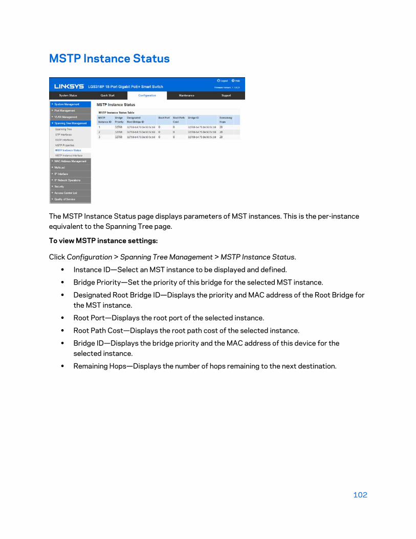
102
MSTP Instance Status
The MSTP Instance Status page displays parameters of MST instances. This is the per-instance equivalent to the Spanning Tree page.
To view MSTP instance settings:
Click Configuration > Spanning Tree Management > MSTP Instance Status.
• Instance ID—Select an MST instance to be displayed and defined.
• Bridge Priority—Set the priority of this bridge for the selected MST instance.
• Designated Root Bridge ID—Displays the priority and MAC address of the Root Bridge for the MST instance.
• Root Port—Displays the root port of the selected instance.
• Root Path Cost—Displays the root path cost of the selected instance.
• Bridge ID—Displays the bridge priority and the MAC address of this device for the selected instance.
• Remaining Hops—Displays the number of hops remaining to the next destination.

103
MSTP Instance Interface
The MSTP Instance Interface page enables you to configure the port MSTP settings for every MST instance, and to view information that has currently been learned by the protocol, such as the designated bridge per MST instance.
To configure the ports in an MST instance:
1. Click Configuration > Spanning Tree Management > MSTP Instance Interface.
2. Enter the parameters.
• MSTP Instance—Select the MSTP instance to be configured.
• Interface Type—Select whether to display the list of ports or LAGs.
3. Click Search. The following MSTP parameters for the interfaces on the instance are displayed:
• Interface—Select the interface for which the MSTI settings are to be defined.
• Interface Priority—Set the port priority for the specified interface and MST instance.
• Path Cost—Enter the port contribution to the root path cost in the User Defined textbox or select Use Default to use the default value.
• Port State—Displays the MSTP status of the specific port on a specific MST instance. The parameters are defined as:
o Disabled—STP is currently disabled. o Blocking—The port on this instance is currently blocked, and cannot
forward traffic (with the exception of BPDU data) or learn MAC addresses. o Listening—The port on this instance is in Listening mode. The port cannot
forward traffic, and cannot learn MAC addresses.
104
o Learning—The port on this instance is in Learning mode. The port cannot forward traffic, but it can learn new MAC addresses.
o Forwarding—The port on this instance is in Forwarding mode. The port can forward traffic and learn new MAC addresses.
o Boundary—The port on this instance is a boundary port. It inherits its state from instance 0 and can be viewed on the STP Interface Settings page.
• Port Role—Displays the port or LAG role, per port or LAG per instance, assigned by the MSTP algorithm to provide STP paths:
o Root—Forwarding packets through this interface provides the lowest cost path for forwarding packets to the root device.
o Designated—The interface through which the bridge is connected to the LAN, which provides the lowest root path cost from the LAN to the Root Bridge for the MST instance.
o Alternate—The interface provides an alternate path to the root device from the root interface.
o Backup—The interface provides a backup path to the designated port path toward the Spanning Tree leaves. Backup ports occur when two ports are connected in a loop by a point-to-point link. Backup ports also occur when a LAN has two or more established connections to a shared segment.
o Disabled—The interface does not participate in the Spanning Tree. o Boundary—The port on this instance is a boundary port. It inherits its state
from instance 0 and can be viewed on the STP Interface Settings page.
• Mode—Displays the current interface Spanning Tree mode. o If the link partner is using MSTP or RSTP, the displayed port mode is RSTP. o If the link partner is using STP, the displayed port mode is STP.
• Type—Displays the MST type of the port. o Boundary—A Boundary port attaches MST bridges to a LAN in a remote
region. If the port is a boundary port, it also indicates whether the device on the other side of the link is working in RSTP or STP mode.
o Internal—The port is an internal port.
• Designated Bridge ID—Displays the ID number of the bridge that connects the link or shared LAN to the root.
• Designated Port ID—Displays the Port ID number on the designated bridge that connects the link or the shared LAN to the root.
• Designated Cost—Displays the cost of the port participating in the STP topology. Ports with a lower cost are less likely to be blocked if STP detects loops.
• Remain Hops—Displays the hops remaining to the next destination.

105
• Forward Transitions—Displays the number of times the port has changed from the Forwarding state to the Blocking state.
4. Select an interface, and click Edit.
5. Enter the parameters.
6. Click Apply. The Running Configuration file is updated.

106
Chapter 8 - MAC Address Management There are two types of MAC addresses—static and dynamic. Depending on their type, MAC addresses are either stored in the Static Address table or in the Dynamic Address table, along with VLAN and port information.
Static addresses are configured by the user, and therefore, they do not expire.
A new source MAC address that appears in a frame arriving at the device is added to the Dynamic Address table. This MAC address is retained for a configurable period of time. If another frame with the same source MAC address does not arrive at the device before that time period expires, the MAC entry is aged (deleted) from the table.
When a frame arrives, the device searches for a corresponding/matching MAC address in the static or dynamic table. If a match is found, the frame is marked for egress on the port specified in the table. If frames are sent to a MAC address that is not found in the tables, they are transmitted/broadcasted to all the ports on the relevant VLAN. Such frames are referred to as unknown Unicast frames.
The device supports a maximum of 8,000 static and dynamic MAC addresses.
Dynamic MAC Addresses
The Dynamic Address Table (bridging table) contains the MAC addresses acquired by monitoring the source addresses of frames entering the device.
To prevent this table from overflowing and to make room for new MAC addresses, an address is deleted if no corresponding traffic is received for a certain period of time known as the aging time.
To configure the aging time for dynamic addresses:
1. Click Configuration > MAC Address Management > Dynamic MAC Addresses.
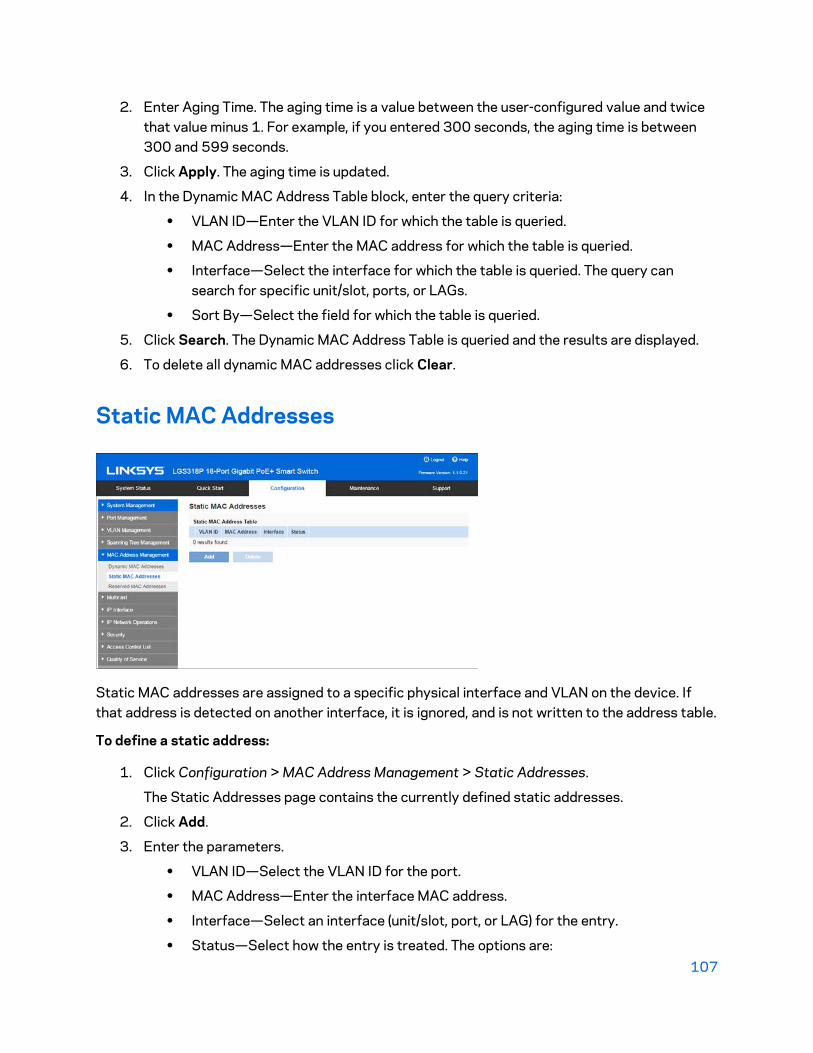
107
2. Enter Aging Time. The aging time is a value between the user-configured value and twice that value minus 1. For example, if you entered 300 seconds, the aging time is between 300 and 599 seconds.
3. Click Apply. The aging time is updated.
4. In the Dynamic MAC Address Table block, enter the query criteria:
• VLAN ID—Enter the VLAN ID for which the table is queried.
• MAC Address—Enter the MAC address for which the table is queried.
• Interface—Select the interface for which the table is queried. The query can search for specific unit/slot, ports, or LAGs.
• Sort By—Select the field for which the table is queried.
5. Click Search. The Dynamic MAC Address Table is queried and the results are displayed.
6. To delete all dynamic MAC addresses click Clear.
Static MAC Addresses
Static MAC addresses are assigned to a specific physical interface and VLAN on the device. If that address is detected on another interface, it is ignored, and is not written to the address table.
To define a static address:
1. Click Configuration > MAC Address Management > Static Addresses.
The Static Addresses page contains the currently defined static addresses.
2. Click Add.
3. Enter the parameters.
• VLAN ID—Select the VLAN ID for the port.
• MAC Address—Enter the interface MAC address.
• Interface—Select an interface (unit/slot, port, or LAG) for the entry.
• Status—Select how the entry is treated. The options are:

108
o Permanent—The system never removes this MAC address. If the static MAC address is saved in the Startup Configuration, it is retained after rebooting.
o Delete on reset—The static MAC address is deleted when the device is reset.
o Delete on timeout—The MAC address is deleted when aging occurs. o Secure—The MAC address is secure when the interface is in classic locked
mode (see Port Security).
4. Click Apply. A new entry appears in the table.
Reserved MAC Addresses
When the device receives a frame with a destination MAC address that belongs to a reserved range (per the IEEE standard), the frame can be discarded or bridged. The entry in the Reserved MAC Address Table can either specify the reserved MAC address or the reserved MAC address and a frame type.
To add an entry for a reserved MAC address:
1. Click Configuration > MAC Address Management > Reserved MAC Addresses.
2. Click Add.
3. Enter the values for the following fields:
• MAC Address—Select the MAC address to be reserved.
• Frame Type—Select a frame type based on the following criteria: o Ethernet II—Applies to Ethernet II packets with the specific MAC address
and ethertype. o LLC—Applies to Logical Link Control (LLC) packets with the specific MAC
address and DSAP-SSAP.

109
o LLC-SNAP—Applies to Logical Link Control/Sub-Network Access Protocol (LLC-SNAP) packets with the specific MAC address.
o All—Applies to all packets with the specific MAC address and protocol.
• Action—Select one of the following actions to be taken upon receiving a packet that matches the selected criteria:
o Bridge—Forward the packet to all VLAN members. o Discard—Delete the packet.
4. Click Apply. A new MAC address is reserved.

110
Chapter 9 – Multicast Multicast forwarding enables one-to-many information dissemination. Multicast applications are useful for dissemination of information to multiple clients, where clients do not require reception of the entire content. A typical application is a cable-TV-like service, where clients can join a channel in the middle of a transmission, and leave before it ends.
The data is sent only to relevant ports. Forwarding the data only to the relevant ports conserves bandwidth and host resources on links.
For Multicast forwarding to work across IP subnets, nodes and routers must be Multicast-capable. A Multicast-capable node must be able to do the following:
• Send and receive Multicast packets.
• Register the Multicast addresses being listened to by the node with local routers, so that local and remote routers can route the Multicast packet to the nodes.
Typical Multicast Setup
While Multicast routers route Multicast packets between IP subnets, Multicast- capable Layer 2 switches forward Multicast packets to registered nodes within a LAN or VLAN.
A typical setup involves a router that forwards the Multicast streams between private and/or public IP networks, a device with Internet Group Membership Protocol (IGMP) snooping capabilities, and a Multicast client that wants to receive a Multicast stream. In this setup, the router sends IGMP queries periodically.
These queries reach the device, which in turn floods the queries to the VLAN, and also learns the port where there is a Multicast router (Mrouter). When a host receives the IGMP query message, it responds with an IGMP Join message saying that the host wants to receive a specific Multicast stream and optionally from a specific source. The device with IGMP snooping analyzes the Join messages, and learns that the Multicast stream the host has requested must be forwarded to this specific port. It then forwards the IGMP Join to the Mrouter only. Similarly, when the Mrouter receives an IGMP Join message, it learns the interface from which it received the Join messages that wants to receive a specific Multicast stream. The Mrouter forwards the requested Multicast stream to the interface.
In a Layer 2 Multicast service, a Layer 2 switch receives a single frame addressed to a specific Multicast address. It creates copies of the frame to be transmitted on each relevant port.
When the device is IGMP snooping-enabled and receives a frame for a Multicast stream, it forwards the Multicast frame to all the ports that have registered to receive the Multicast stream using IGMP Join messages.

111
The device can forward Multicast streams based on one of the following options:
• Multicast MAC Group Address
• IP Multicast Group Address (G)
• A combination of the source IP address (S) and the destination IP Multicast Group Address (G) of the Multicast packet.
• One of these options can be configured per VLAN.
The system maintains lists of Multicast groups for each VLAN, and this manages the Multicast information that each port should receive. The Multicast groups and their receiving ports can be configured statically or learned dynamically using IGMP snooping.
Multicast registration is the process of listening and responding to Multicast registration protocols. The available protocols are IGMP for IPv4.
When IGMP snooping is enabled in a device on a VLAN, it analyzes the IGMP packets it receives from the VLAN connected to the device and Multicast routers in the network.
When a device learns that a host is using IGMP messages to register to receive a Multicast stream, optionally from a specific source, the device adds the registration to its Multicast Forwarding Data Base (MFDB).
IGMP snooping can effectively reduce Multicast traffic from streaming bandwidth- intensive IP applications. A device using IGMP snooping only forwards Multicast traffic to the hosts interested in that traffic. This reduction of Multicast traffic reduces the packet processing at the device, and also reduces the workload of the end hosts, since they do not have to receive and filter all of the Multicast traffic generated in the network. This device supports IGMP v1/v2/v3.
Multicast Address Properties
Each IPv4 Multicast address is in the address range 224.0.0.0 to 239.255.255.255.
To map an IP Multicast group address to a Layer 2 Multicast address for IPv4, take the 23 low-order bits from the IPv4 address, and add them to the 01:00:5e prefix. By standard, the upper nine bits of the IP address are ignored. IP addresses that differ only in the value of the upper nine bits are mapped to the same Layer 2 address because the lower 23 bits are identical. For example, 234.129.2.3 is mapped to a MAC Multicast group address 01:00:5e:01:02:03. Up to 32 IP Multicast group addresses can be mapped to the same Layer 2 address.
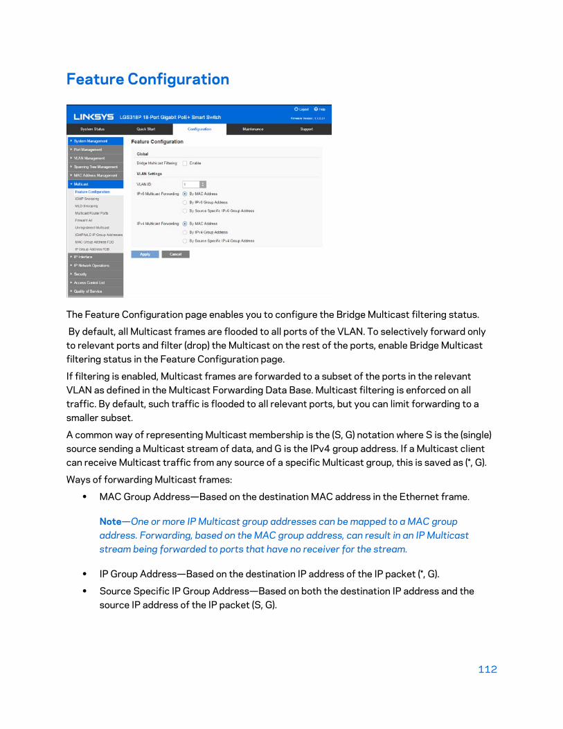
112
Feature Configuration
The Feature Configuration page enables you to configure the Bridge Multicast filtering status.
By default, all Multicast frames are flooded to all ports of the VLAN. To selectively forward only to relevant ports and filter (drop) the Multicast on the rest of the ports, enable Bridge Multicast filtering status in the Feature Configuration page.
If filtering is enabled, Multicast frames are forwarded to a subset of the ports in the relevant VLAN as defined in the Multicast Forwarding Data Base. Multicast filtering is enforced on all traffic. By default, such traffic is flooded to all relevant ports, but you can limit forwarding to a smaller subset.
A common way of representing Multicast membership is the (S, G) notation where S is the (single) source sending a Multicast stream of data, and G is the IPv4 group address. If a Multicast client can receive Multicast traffic from any source of a specific Multicast group, this is saved as (*, G).
Ways of forwarding Multicast frames:
• MAC Group Address—Based on the destination MAC address in the Ethernet frame.
Note—One or more IP Multicast group addresses can be mapped to a MAC group address. Forwarding, based on the MAC group address, can result in an IP Multicast stream being forwarded to ports that have no receiver for the stream.
• IP Group Address—Based on the destination IP address of the IP packet (*, G).
• Source Specific IP Group Address—Based on both the destination IP address and the source IP address of the IP packet (S, G).

113
By selecting the forwarding mode, you can define the method used by hardware to identify Multicast flow by one of the following options: MAC Group Address, IP Group Address, or Source Specific IP Group Address. (S, G) is supported by IGMPv3, while IGMPv1/2 support only (*, G), which is just the group ID. The device supports a maximum of 256 static and dynamic Multicast group addresses. To enable Multicast filtering, and select the forwarding method:
1. Click Configuration > Multicast > Feature Configuration.
2. Bridge Multicast Filtering—Select to enable filtering of Multicast addresses.
3. VLAN ID—Select the VLAN ID to set its forwarding method.
4. IPv6 Multicast Forwarding—Select one of the following options:
• By MAC Address—Select to enable the MAC address method for forwarding Multicast packets.
• By IPv6 Group Address—Select to enable the IPv4 group address method for forwarding Multicast packets.
• By Source Specific IPv6 Group Address—Select to enable the source-specific IPv6 group address method for forwarding Multicast packets.
5. IPv4 Multicast Forwarding—Select one of the following options:
• By MAC Address—Select to enable the MAC address method for forwarding Multicast packets.
• By IPv4 Group Address—Select to enable the IPv4 group address method for forwarding Multicast packets.
• By Source Specific IPv4 Group Address—Select to enable the source-specific IPv4 group address method for forwarding Multicast packets.
6. Click Apply. The Running Configuration file is updated.

114
IGMP Snooping
To enable IGMP Snooping and identify the device as an IGMP Snooping Querier on a VLAN:
1. Click Configuration > Multicast > IGMP Snooping.
2. Enable IGMP Snooping.
When IGMP Snooping is enabled globally, the device monitoring network traffic can determine which hosts have requested to receive Multicast traffic.
The device only performs IGMP Snooping if both IGMP snooping and Bridge Multicast filtering are enabled.
3. Select a VLAN, and click Edit.
4. Enter the parameters:
• VLAN ID-Select the VLAN ID on which IGMP snooping is defined.
• IGMP Snooping Status-Enable or disable the monitoring of network traffic for the selected VLAN.
• Auto Learn MRouter Ports -Select to enable auto learning of the ports to which the Mrouter is connected.
• Immediate Leave-Select to enable Immediate Leave to decrease the time it takes to block a Multicast stream sent to a member port when an IGMP Group Leave message is received on that port.
• IGMP Querier-Select to enable the IGMP Querier.
• IGMP Querier Version-Select the IGMP version used if the device becomes the elected querier. Select IGMPv3 if there are switches and/or Multicast routers in the VLAN that perform source-specific IP Multicast forwarding.

115
• Querier Source IP Address-Select the source IP address of the IGMP Querier. The following options are available:
o Auto-The system decides whether to use the IP address of the VLAN or the management IP address.
o User Defined-This can be the IP address of the VLAN or it can be the management IP address.
5. Click Apply. The Running Configuration file is updated.
MLD Snooping
To enable MLD Snooping and configure it on a VLAN:
1. Click Configuration > Multicast > MLD Snooping.
When MLD Snooping is globally enabled, the device monitoring network traffic can determine which hosts have requested to receive Multicast traffic. The device performs MLD Snooping only if both MLD snooping and Bridge Multicast filtering are enabled.
2. Enable MLD Snooping.
3. Choose a VLAN ID.
4. Click Edit.
5. Enable or disable the following features for the selected VLAN:
• VLAN ID—Select a VLAN on which to configure MLD Snooping.
• MLD Snooping Status—Select to enable MLD snooping globally on all interfaces.
• Auto-Learn MRouter Ports—Select to enable Auto Learn of the Multicast router.

116
• Immediate Leave—Select to enable the switch to remove an interface that sends a leave message from the forwarding table without first sending out MAC-based general queries to the interface. When an MLD Leave Group message is received from a host, the system removes the host port from the table entry. After it relays the MLD queries from the Multicast router, it deletes entries periodically if it does not receive any MLD membership reports from the Multicast clients. When enabled, this feature reduces the time it takes to block unnecessary MLD traffic sent to a device port.
6. Click Apply. The Running Configuration file is updated.
Multicast Router Ports
A Multicast router (Mrouter) port is a port that connects to a Multicast router. The device includes the Multicast router port(s) numbers when it forwards the Multicast streams and IGMP registration messages. This is required so that the Multicast routers can, in turn, forward the Multicast streams and propagate the registration messages to other subnets.
To statically configure or see dynamically-detected ports connected to the Multicast router:
1. Click Configuration > Multicast > Multicast Router Ports.
2. Enter some or all of following query filter criteria:
• VLAN ID—Select the VLAN ID for the router ports that are described
• IP Version--Select IPv4 or IPv6
• Interface Type—Select whether to display ports or LAGs.

117
3. Click Search. The interfaces matching the query criteria are displayed.
For each port or LAG, select its association type.
• Static—The port is statically configured as a Multicast router port.
• Dynamic—(Display only) The port is dynamically configured as a Multicast router port by a IGMP query. To enable the dynamic learning of Multicast router ports, go to the IGMP Snooping page.
• Forbidden—This port is not to be configured as a Multicast router port, even if IGMP queries are received on this port. If Forbidden is enabled on a port, Mrouter is not learned on this port (i.e. MRouter Ports Auto-Learn is not enabled on this port).
• None—The port is not currently a Multicast router port.
4. Click Apply to update the device.
Forward All
The Forward All page enables and displays the configuration of the ports and/ or LAGs that are to receive Multicast streams from a specific VLAN. This feature requires that Bridge Multicast filtering in the Feature Configuration page be enabled. If it is disabled, then all Multicast traffic is flooded to ports in the device.
You can statically (manually) configure a port to Forward All, if the devices connecting to the port do not support IGMP.
IGMP messages are not forwarded to ports defined as Forward All.
Note—The configuration affects only the ports that are members of the selected VLAN.
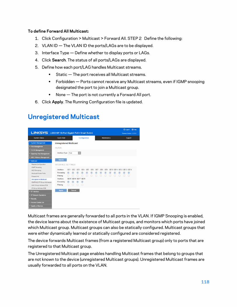
118
To define Forward All Multicast:
1. Click Configuration > Multicast > Forward All. STEP 2 Define the following:
2. VLAN ID — The VLAN ID the ports/LAGs are to be displayed.
3. Interface Type — Define whether to display ports or LAGs.
4. Click Search. The status of all ports/LAGs are displayed.
5. Define how each port/LAG handles Multicast streams.
• Static — The port receives all Multicast streams.
• Forbidden — Ports cannot receive any Multicast streams, even if IGMP snooping designated the port to join a Multicast group.
• None — The port is not currently a Forward All port.
6. Click Apply. The Running Configuration file is updated.
Unregistered Multicast
Multicast frames are generally forwarded to all ports in the VLAN. If IGMP Snooping is enabled, the device learns about the existence of Multicast groups, and monitors which ports have joined which Multicast group. Multicast groups can also be statically configured. Multicast groups that were either dynamically learned or statically configured are considered registered.
The device forwards Multicast frames (from a registered Multicast group) only to ports that are registered to that Multicast group.
The Unregistered Multicast page enables handling Multicast frames that belong to groups that are not known to the device (unregistered Multicast groups). Unregistered Multicast frames are usually forwarded to all ports on the VLAN.
119
You can select a port to receive or filter unregistered Multicast streams. The configuration is valid for any VLAN of which it is a member (or will be a member).
This feature ensures that the customer receives only the Multicast groups requested and not others that may be transmitted in the network.
To define unregistered Multicast settings:
1. Click Configuration > Multicast > Unregistered Multicast.
2. Define the following:
• Interface Type — Define whether to display ports or LAGs.
• Interface Settings — Displays the forwarding status of the selected interface. The possible values are as follows:
• Forwarding — Enables forwarding of unregistered Multicast frames to the selected interface.
• Filtering — Enables filtering (rejecting) of unregistered Multicast frames to the selected interface.
3. Click Apply. The settings are saved, and the Running Configuration file is updated.

120
IGMP/MLD IP Group Addresses
The IGMP IP Group Addresses page displays the IPv4 group address learned from IGMP messages.
There might be a difference between information on this page and, for example, information displayed in the MAC Group Address FDB page. Assuming that the system is in MAC-based groups and a port that requested to join the following Multicast groups 224.1.1.1 and 225.1.1.1, both are mapped to the same MAC Multicast address 01:00:5e:01:01:01. In this case, there is a single entry in the MAC Group Address FDB page, but two entries on this page.
To query for an IP Multicast group:
1. Click Configuration > Multicast > IGMP IP Group Addresses.
2. Enter some or all of following query filter criteria:
• VLAN ID — Defines the VLAN ID to query.
• IP Group Address — Defines the Multicast group MAC address or IP address to query.
• Source IP Address — Defines the sender address to query.
3. Click Search.
The following fields are displayed for each Multicast group:
• Dynamic IP Group Type
• VLAN ID — The VLAN ID.
• IP Group Address — The Multicast group MAC address or IP address.
• Source IP Address — The sender address for all of the specified group ports.
• Included Ports — The list of destination ports for the Multicast stream.

121
• Excluded Ports — The list of ports not included in the group.
• Compatibility Mode — The oldest IGMP version of registration from the hosts the device receives on the IP group address.
MAC Group Address FDB
The device supports forwarding incoming Multicast traffic based on the Multicast group information. This information is derived from the IGMP packets received or as the result of manual configuration, and it is stored in the Multicast Forwarding Database (MFDB). When a frame is received from a VLAN that is configured to forward Multicast streams, based on MAC group addresses, and its destination address is a Layer 2.
Multicast address, the frame is forwarded to all ports that are members of the MAC group address.
The MAC Group Address FDB page has the following functions:
• Query and view information from the MFDB, relating to a specific VLAN ID or a specific MAC address group. This data is acquired either dynamically through IGMP snooping or statically by manual entry.
• Add or delete static entries to the MFDB that provide static forwarding information, based on MAC destination addresses.
• Display a list of all ports/LAGs that are a member of each VLAN ID and MAC address group, and enter whether traffic is forwarded to it or not.
122
To define and view MAC Multicast groups:
1. Click Configuration > Multicast > MAC Group Address FDB.
2. Enter the parameters.
• VLAN ID —Enter the VLAN ID of the group to be displayed.
• MAC Group Address —Set the MAC address of the Multicast group to be displayed. If no MAC Group Address is specified, the page contains all the MAC Group Addresses from the selected VLAN.
3. Click Search, and the MAC Multicast group addresses are displayed in the lower block.
Entries that were created both in this page and in the IP Group Address FDB page are displayed. For those created in the IP Group Address FDB page, the IP addresses are converted to MAC addresses.
4. Click Add to add a static MAC Group Address.
5. Enter the parameters.
• VLAN ID — Defines the VLAN ID of the new Multicast group.
• MAC Group Address — Defines the MAC address of the new Multicast group.
6. Click Apply, the MAC Multicast group is saved to the Running Configuration file.
To configure and display the registration for the interfaces within the group, select an address, and click Membership.
The MAC Group Address FDB page opens. Enter the following:
• VLAN ID—The VLAN ID of the Multicast group.
• MAC Group Address—The MAC address of the group.
• Interface Type—Port or LAG.
7. Click Search to display the port or LAG membership.
8. Select the way that each interface is associated with the Multicast group:
• Static—Attaches the interface to the Multicast group as a static member.
• Dynamic—Indicates that the interface was added to the Multicast group as a result of IGMP snooping.
• Forbidden—Specifies that this port is not allowed to join this group on this VLAN.
• Excluded—Specifies that the port is not currently a member of this Multicast group on this VLAN.
9. Click Apply, and the Running Configuration file is updated.
Note—Entries that were created in the IP Group Address FDB page cannot be deleted in this page (even if they are selected).

123
IP Group Address FDB
The IP Group Address FDB page enables querying and adding IP Multicast groups contained in the IP Multicast Groups Forwarding Data Base.
To define and view IP Multicast groups:
1. Click Configuration > Multicast > IP Group Address FDB.
The page contains all of the IP Multicast group addresses learned by snooping.
2. Enter the parameters required for filtering.
• VLAN ID—Enter the VLAN ID of the group to be displayed.
• IP Group Address—Define the IP address of the Multicast group to be displayed. This is only relevant when the Forwarding Mode is (S, G).
• Source IP Address—Define the source IP address of the sending device. If mode is (S, G), enter the sender S. This together with the IP group address is the Multicast group ID (S,G) to be displayed. If mode is (*, G), enter an * to indicate that the Multicast group is only defined by destination.
3. Click Search. The results are displayed in the lower block..
4. Click Add to add a static IP Multicast group address.
5. Enter the parameters.
• VLAN ID—Defines the VLAN ID of the group to be added.
• IP Group Address—Define the IP address of the new Multicast group. Group Address Settings
• Source Specific IP Multicast—Select to indicate that the entry contains a specific source, and adds the address in the IP Source Address field. If not, the entry is added as a (*,G) entry, an IP group address from any IP source.
• Source IP Address—Enter the source address to be included.
124
6. Click Apply. The IP Multicast group is added, and the device is updated.
To configure and display the registration of an IP group address, select an address and click Membership.
The VLAN ID, IP Version, IP Multicast group address, and Source IP address selected are displayed as read-only in the top of the window. You can select whether to display ports or LAGs.
7. For each interface, select its association type.
• Static—Attaches the interface to the Multicast group as a static member.
• Dynamic—Indicates that the interface was added to the Multicast group as a result of IGMP snooping.
• Forbidden—Specifies that this port is forbidden from joining this group on this VLAN.
• Excluded—Indicates that the port is not currently a member of this Multicast group on this VLAN. This is selected by default until Static or Forbidden is selected.
8. Click Apply. The Running Configuration file is updated.

125
Chapter 10 - IP Interface
IPv4
Layer 2 IP Addressing
The device has one IPv4 address and up to two IPv6 interfaces in the management VLAN. This IP address and the default gateway can be configured manually, or by DHCP. The static IP address and default gateway are configured on the IPv4 Interface page. The device uses the default gateway, if configured, to communicate with devices that are not in the same IP subnet as the device. By default, VLAN 1 is the management VLAN, but this can be modified. The device can only be reached at the configured IP address through its management VLAN.
The factory default setting of the IPv4 address configuration is DHCPv4. This means that the device acts as a DHCPv4 client, and sends out a DHCPv4 request during boot up.
If the device receives a DHCPv4 response from the DHCPv4 server with an IPv4 address, it sends Address Resolution Protocol (ARP) packets to confirm that the IP address is unique. If the ARP response shows that the IPv4 address is in use, the device sends a DHCPDECLINE message to the offering DHCP server, and sends another DHCPDISCOVER packet that restarts the process.
If the device does not receive a DHCPv4 response in 60 seconds, it continues to send DHCPDISCOVER queries, and adopts the default IPv4 address: 192.168.1.251/24.
IP address collisions occur when the same IP address is used in the same IP subnet by more than one device. Address collisions require administrative actions on the DHCP server and/or the devices that collide with the device.
When a VLAN is configured to use dynamic IP addresses, the device issues DHCPv4 requests until it is assigned an IPv4 address from a DHCPv4 server. The management VLAN can be configured with a static or dynamic IP address.
The IP address assignment rules for the device:
• Unless the device is configured with a static IPv4 address, it issues DHCPv4 queries until a response is received from a DHCPv4 server.
• If the IP address on the device is changed, the device issues gratuitous ARP packets to the corresponding VLAN to check IP address collisions. This rule also applies when the device reverts to the default IP address.
• The system status LED changes to solid blue when a new unique IP address is received from the DHCP server. If a static IP address has been set, the system status LED also changes to solid blue. The LED flashes when the device is acquiring an IP address and is currently using the factory default IP address 192.168.1. 251.
• The same rules apply when a client must renew the lease, prior to its expiration date through a DHCPREQUEST message.

126
• With factory default settings, when no statically defined or DHCP- acquired IP address is available, the default IP address is used. When the other IP addresses become available, the addresses are automatically used. The default IP address is always on the management VLAN.
IPv4 Interface
To manage the device by using the web-based configuration utility, the IPv4 device management IP address must be defined and known. The device IP address can be manually configured or automatically received from a DHCP server.
To configure the IPv4 device IP address:
1. Click Configuration > IP Interface > IPv4 > IPv4 Interface.
2. Enter values for the following fields:
• Management VLAN—Select the Management VLAN used to access the device through telnet or the Web GUI. VLAN1 is the default Management VLAN.
• IP Address Type—Select one of the following options: o Dynamic (DHCP)—Discover the IP address using DHCP from the
management VLAN. o Static IP Address—Manually define a static IP address.
Note—DHCP Option 12 (Host Name option) is supported when the device is a DHCP client. If DHCP Option 12 is received from a DHCP server, it is saved as the server’s host name. DHCP option 12 will not be requested by the device. The DHCP server must be configured to send option 12, regardless of what is requested in order to make use of this feature.
• Dynamic IP Address—Select to renew the DHCP-supplied IP address.
• IP Address—Enter the IP address, and configure one of the following Mask fields: o IP Subnet Mask—Configure one of the following Mask fields:
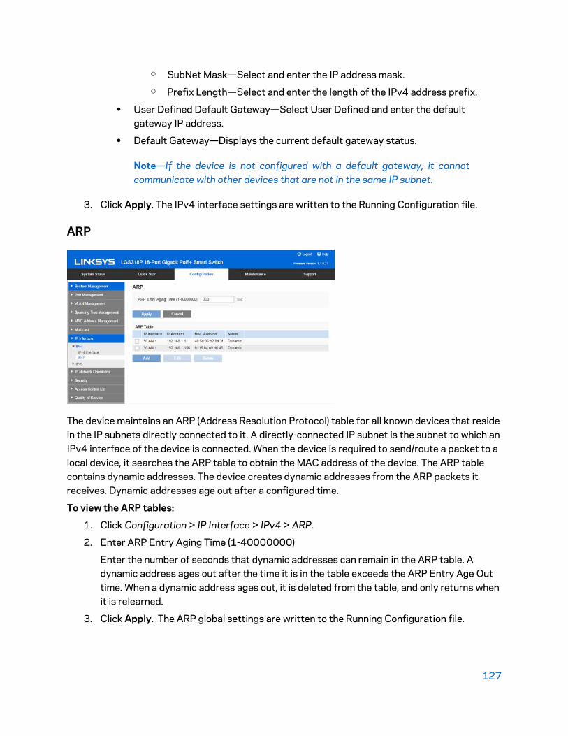
127
o SubNet Mask—Select and enter the IP address mask. o Prefix Length—Select and enter the length of the IPv4 address prefix.
• User Defined Default Gateway—Select User Defined and enter the default gateway IP address.
• Default Gateway—Displays the current default gateway status.
Note—If the device is not configured with a default gateway, it cannot communicate with other devices that are not in the same IP subnet.
3. Click Apply. The IPv4 interface settings are written to the Running Configuration file.
ARP
The device maintains an ARP (Address Resolution Protocol) table for all known devices that reside in the IP subnets directly connected to it. A directly-connected IP subnet is the subnet to which an IPv4 interface of the device is connected. When the device is required to send/route a packet to a local device, it searches the ARP table to obtain the MAC address of the device. The ARP table contains dynamic addresses. The device creates dynamic addresses from the ARP packets it receives. Dynamic addresses age out after a configured time.
To view the ARP tables:
1. Click Configuration > IP Interface > IPv4 > ARP.
2. Enter ARP Entry Aging Time (1-40000000)
Enter the number of seconds that dynamic addresses can remain in the ARP table. A dynamic address ages out after the time it is in the table exceeds the ARP Entry Age Out time. When a dynamic address ages out, it is deleted from the table, and only returns when it is relearned.
3. Click Apply. The ARP global settings are written to the Running Configuration file.

128
The ARP table displays the following fields:
• IP Interface—The IPv4 Interface of the directly-connected IP subnet where the IP device resides.
• IP Address—The IP address of the IP device.
• MAC Address—The MAC address of the IP device.
• Status—Whether the entry was manually entered (static) or dynamically learned. To add a static ARP entry:
1. Click Add.
2. Enter the parameters:
• Interface—An IPv4 interface can be configured on a port, LAG or VLAN. Select the desired interface from the list of configured IPv4 interfaces on the device.
• IP Address—Enter the IP address of the local device.
• MAC Address—Enter the MAC address of the local device.
3. Click Apply. The ARP entry is saved to the Running Configuration file
IPv6
The Internet Protocol version 6 (IPv6) is a network-layer protocol for packet-switched Internet works. IPv6 was designed to replace IPv4, the predominantly deployed Internet protocol.
IPv6 introduces greater flexibility in assigning IP addresses because the address size increases from 32-bit to 128-bit addresses. IPv6 addresses are written as eight groups of four hexadecimal digits, for example FE80:0000:0000:0000:0000:9C00:876A:130B. The abbreviated form, in which a group of zeroes can be left out, and replaced with ‘::’ is also acceptable, for example, ::-FE80::9C00:876A:130B.
IPv6 nodes require an intermediary mapping mechanism to communicate with other IPv6 nodes over an IPv4-only network. This mechanism, called a tunnel, enables IPv6-only hosts to reach IPv4 services, and enables isolated IPv6 hosts and networks to reach an IPv6 node over the IPv4 infrastructure.
The device detects IPv6 frames by the IPv6 Ethertype.
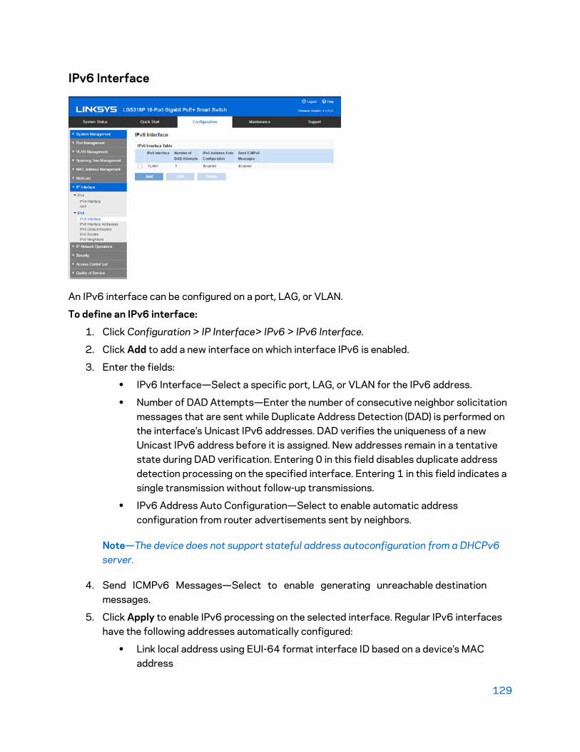
129
IPv6 Interface
An IPv6 interface can be configured on a port, LAG, or VLAN.
To define an IPv6 interface:
1. Click Configuration > IP Interface> IPv6 > IPv6 Interface.
2. Click Add to add a new interface on which interface IPv6 is enabled.
3. Enter the fields:
• IPv6 Interface—Select a specific port, LAG, or VLAN for the IPv6 address.
• Number of DAD Attempts—Enter the number of consecutive neighbor solicitation messages that are sent while Duplicate Address Detection (DAD) is performed on the interface’s Unicast IPv6 addresses. DAD verifies the uniqueness of a new Unicast IPv6 address before it is assigned. New addresses remain in a tentative state during DAD verification. Entering 0 in this field disables duplicate address detection processing on the specified interface. Entering 1 in this field indicates a single transmission without follow-up transmissions.
• IPv6 Address Auto Configuration—Select to enable automatic address configuration from router advertisements sent by neighbors.
Note—The device does not support stateful address autoconfiguration from a DHCPv6 server.
4. Send ICMPv6 Messages—Select to enable generating unreachable destination messages.
5. Click Apply to enable IPv6 processing on the selected interface. Regular IPv6 interfaces have the following addresses automatically configured:
• Link local address using EUI-64 format interface ID based on a device’s MAC address

130
• All link local Multicast addresses (FF02::1)
• Solicited-Node Multicast address (format FF02::1:FFXX:XXXX)
IPv6 Interface Addresses
To assign an IPv6 address to an IPv6 Interface:
1. Click Configuration > IP Interface> IPv6 > IPv6 Interface Addresses.
2. To filter the table, select an interface name, and click Search. The interface appears in the IPv6 Address Table.
3. Click Add.
4. Enter values for the fields.
• IPv6 Interface—Displays the interface on which the IPv6 address is to be defined. If an * is displayed, the IPv6 interface is not enabled but has been configured.
• IPv6 Address Type—Select the type of the IPv6 address to add.
• Link Local—An IPv6 address that uniquely identifies hosts on a single network link. A link local address has a prefix of FE80, is not routable, and can be used for communication only on the local network. Only one link local address is supported. If a link local address exists on the interface, this entry replaces the address in the configuration.
• Global—An IPv6 address that is a global Unicast IPV6 type that is visible and reachable from other networks.
• IPv6 Address—In Layer 2, the device supports a singleIPv6 interface. In addition to the default link local and Multicast addresses, the device also automatically adds global addresses to the interface based on the router advertisements it receives. The device supports a maximum of 128 addresses at the interface. Each address must be a valid IPv6 address that is specified in hexadecimal format by using 16-bit values separated by colons.
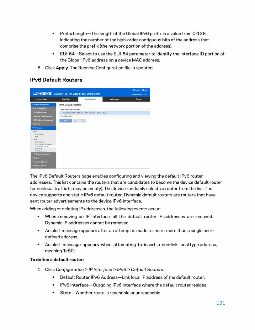
131
• Prefix Length—The length of the Global IPv6 prefix is a value from 0-128 indicating the number of the high-order contiguous bits of the address that comprise the prefix (the network portion of the address).
• EUI-64—Select to use the EUI-64 parameter to identify the interface ID portion of the Global IPv6 address on a device MAC address.
5. Click Apply. The Running Configuration file is updated.
IPv6 Default Routers
The IPv6 Default Routers page enables configuring and viewing the default IPv6 router addresses. This list contains the routers that are candidates to become the device default router for nonlocal traffic (it may be empty). The device randomly selects a router from the list. The device supports one static IPv6 default router. Dynamic default routers are routers that have sent router advertisements to the device IPv6 interface.
When adding or deleting IP addresses, the following events occur:
• When removing an IP interface, all the default router IP addresses are removed. Dynamic IP addresses cannot be removed.
• An alert message appears after an attempt is made to insert more than a single user-defined address.
• An alert message appears when attempting to insert a non-link local type address, meaning ‘fe80:’.
To define a default router:
1. Click Configuration > IP Interface > IPv6 > Default Routers.
• Default Router IPv6 Address—Link local IP address of the default router.
• IPv6 Interface—Outgoing IPv6 interface where the default router resides.
• State—Whether route is reachable or unreachable.

132
• Type — The default router configuration that includes the following options:
• Static—The default router was manually added to this table through the Add button.
• Dynamic—The default router was dynamically configured.
2. Click Add to add a static default router.
3. Enter the following fields:
• IPv6 Interface—Displays the outgoing Link Local interface.
• Default Router IPv6 Address—The IP address of the default router
4. Click Apply. The default router is saved to the Running Configuration file.
IPv6 Routes
The IPv6 Forwarding Table contains the various routes that have been configured. One of these routes is a default route (IPv6 address:0) that uses the default router selected from the IPv6 Default Router List to send packets to destination devices that are not in the same IPv6 subnet as the device. In addition to the default route, the table also contains dynamic routes that are ICMP redirect routes received from IPv6 routers by using ICMP redirect messages. This could happen when the default router the device uses is not the router for traffic to which the IPv6 subnets that the device wants to communicate.
To view IPv6 routes:
1. Click Configuration > IP Interface > IPv6 > IPv6 Routes.
This page displays the following fields:
• IPv6 Subnet Address—The IPv6 subnet address.
• Prefix Length—IP route prefix length for the destination IPv6 subnet address. It is preceded by a forward slash.
• IPv6 Interface—Interface used to forward the packet.

133
• Next Hop Router IPv6 Address—Address where the packet is forwarded.
Typically, this is the address of a neighboring router. It can be one of the following types.
o Link Local—An IPv6 interface and IPv6 address that uniquely identifies hosts on a single network link. A link local address has a prefix of FE80, is not routable, and can be used for communication only on the local network. Only one link local address is supported. If a link local address exists on the interface, this entry replaces the address in the configuration.
o Global—An IPv6 address that is a global Unicast IPV6 type that is visible and reachable from other networks.
o Point-to-Point—A Point-to-point tunnel.
• Metric—Value used for comparing this route to other routes with the same destination in the IPv6 router table. All default routes have the same value.
• Lifetime—Time period during which the packet can be sent, and resent, before being deleted.
• Route Type—How the destination is attached, and the method used to obtain the entry. The following values are:
• Local—A directly-connected network whose prefix is derived from a manually-configured device’s IPv6 address.
o Dynamic—The destination is an indirectly-attached (remote) IPv6 subnet address. The entry was obtained dynamically via the ND or ICMP protocol.
IPv6 Neighbors
134
The IPv6 Neighbors page enables configuring and viewing the list of IPv6 neighbors on the IPv6 interface. The IPv6 Neighbor Table (also known as IPv6 Neighbor Discovery Cache) displays the MAC addresses of the IPv6 neighbors that are in the same IPv6 subnet as the device. This is the IPv6 equivalent of the IPv4 ARP Table. When the device needs to communicate with its neighbors, the device uses the IPv6 Neighbor Table to determine the MAC addresses based on their IPv6 addresses.
This page displays the neighbors that were automatically detected. Each entry displays to which interface the neighbor is connected, the neighbor’s IPv6 and MAC addresses, the entry type), and the state of the neighbor.
To define IPv6 neighbors:
Click Configuration > IP Interface > IPv6 > IPv6 Neighbors.
The following fields are displayed for the neighboring interfaces:
• IPv6 Interface—Neighboring IPv6 interface type.
• IPv6 Address—IPv6 address of a neighbor.
• MAC Address—MAC address mapped to the specified IPv6 address.
• Type—Neighbor discovery cache information entry type.
• State—Specifies the IPv6 neighbor status. The values are: o Incomplete—Address resolution is working. The neighbor has not yet responded. o Reachable—Neighbor is known to be reachable. o Stale—Previously-known neighbor is unreachable. No action is taken to verify its
reachability until traffic must be sent. o Delay—Previously-known neighbor is unreachable. The interface is in Delay state
for a predefined Delay Time. If no reachability confirmation is received, the state changes to Probe.
o Probe—Neighbor is no longer known to be reachable, and Unicast Neighbor Solicitation probes are being sent to verify the reachability.

135
Chapter 11 - IP Network Operations Domain Name System The Domain Name System (DNS) translates domain names into IP addresses for the purpose of locating and addressing hosts.
As a DNS client, this device resolves domain names to IP addresses through the use of one or more configured DNS servers.
DNS
Use the DNS page to enable the DNS feature, configure the DNS servers and set the default domain used by the device.
1. Click Configuration > IP Network Operations > Domain Name System > DNS.
2. Enter the following fields:
• DNS—Select to designate the device as a DNS client, which can resolve DNS names into IP addresses through one or more configured DNS servers.
• Default Domain Name—Enter the DNS domain name used to complete unqualified host names. The device appends this to all non-fully qualified domain names (NFQDNs) turning them into FQDNs.
The following fields are displayed for each configured DNS server:
• DNS Server IP Address—IP address of the DNS server.
• DNS Server State — Whether DNS server is Active or Inactive.
• IP Interface — Interface connected to DNS server.
• Preference — Each server has a preference value, a lower value means a higher chance of being used.
• Configuration Source — Source of the server’s IP address (static or DHCPv4 or DHCPv6)

136
Up to eight DNS servers can be defined.
To add a DNS server:
1. Click Add.
2. Enter the parameters.
• IP Version—Select IPv6 or IPv4.
• IPv6 Address Type—Select the IPv6 address type (if IPv6 is used). o Global — The IPv6 address is a global Unicast IPV6 type that is visible and
reachable from other networks. o Link Local — The IPv6 address uniquely identifies hosts on a single network
link. A link local address has a prefix of FE80, is not routable, and can be used for communication only on the local network. Only one link local address is supported. If a link local address exists on the interface, this entry replaces the address in the configuration.
• Interface — If the IPv6 address type is Link Local, select the interface through which it is received.
• DNS Server IP Address — Enter the DNS server IP address.
• Preference — Select a value that determines the order in which the domains are used (from low to high). This effectively determines the order in which unqualified names are completed during DNS queries.
3. Click Apply. The DNS server is saved to the Running Configuration file.
DHCP
DHCP snooping provides a security mechanism to prevent receiving false DHCP response packets and to log DHCP addresses. It does this by treating ports on the device as either trusted or untrusted.
A trusted port is a port that is connected to a DHCP server and is allowed to assign DHCP addresses. DHCP messages received on trusted ports are allowed to pass through the device.
An untrusted port is a port that is not allowed to assign DHCP addresses. By default, all ports are considered untrusted until you declare them trusted in the Interface Settings page.
Option 82
Option 82 (DHCP Relay Agent Information Option) passes port and agent information to a central DHCP server, indicating where an assigned IP address physically connects to the network.
The main goal of option 82 is to help to the DHCP server select the best IP subnet (network pool) from which to obtain an IP address.
The following Option 82 options are available on the device:

137
• DHCP Insertion - Add Option 82 information to packets that do not have foreign Option 82 information.
• DHCP Passthrough - Forward or reject DHCP packets that contain Option 82 information from untrusted ports. On trusted ports, DHCP packets containing Option 82 information are always forwarded.
DHCP Snooping Binding Database
DHCP Snooping builds a database (known as the DHCP Snooping Binding database) derived from information taken from DHCP packets entering the device through trusted ports.
The DHCP Snooping Binding database contains the following data: input port, input VLAN, MAC address of the client, and IP address of the client if it exists.
The DHCP Snooping Binding database is also used by IP Source Guard and Dynamic ARP Inspection features to determine legitimate packet sources.
DHCP Trusted Ports
Ports can be either DHCP trusted or untrusted. By default, all ports are untrusted. To create a port as trusted, use the DHCP Snooping Trusted Interface page. Packets from these ports are automatically forwarded. Packets from trusted ports are used to create the Binding database and are handled as described below.
If DHCP Snooping is not enabled, all ports are trusted by default.
How the DHCP Snooping Binding Database is Built
The following describes how the device handles DHCP packets when both the DHCP client and DHCP server are trusted. The DHCP Snooping Binding database is built in this process.
DHCP Trusted Packet Handling
1. Device sends DHCPDISCOVER to request an IP address or DHCPREQUEST to accept an IP address and lease.
2. Device snoops packet and adds the IP-MAC information to the DHCP Snooping Binding database.
3. Device forwards DHCPDISCOVER or DHCPREQUEST packets.
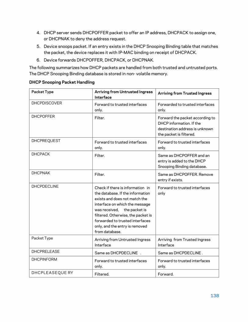
138
4. DHCP server sends DHCPOFFER packet to offer an IP address, DHCPACK to assign one, or DHCPNAK to deny the address request.
5. Device snoops packet. If an entry exists in the DHCP Snooping Binding table that matches the packet, the device replaces it with IP-MAC binding on receipt of DHCPACK.
6. Device forwards DHCPOFFER, DHCPACK, or DHCPNAK.
The following summarizes how DHCP packets are handled from both trusted and untrusted ports. The DHCP Snooping Binding database is stored in non- volatile memory.
DHCP Snooping Packet Handling
Packet Type Arriving from Untrusted Ingress Interface
Arriving from Trusted Ingress
DHCPDISCOVER Forward to trusted interfaces only.
Forwarded to trusted interfaces only.
DHCPOFFER Filter. Forward the packet according to DHCP information. If the destination address is unknown the packet is filtered.
DHCPREQUEST Forward to trusted interfaces only.
Forward to trusted interfaces only.
DHCPACK Filter. Same as DHCPOFFER and an entry is added to the DHCP Snooping Binding database.
DHCPNAK Filter. Same as DHCPOFFER. Remove entry if exists.
DHCPDECLINE Check if there is information in the database. If the information exists and does not match the interface on which the message was received, the packet is filtered. Otherwise, the packet is forwarded to trusted interfaces only, and the entry is removed from database.
Forward to trusted interfaces only
Packet Type Arriving from Untrusted Ingress Interface
Arriving from Trusted Ingress Interface
DHCPRELEASE Same as DHCPDECLINE . Same as DHCPDECLINE .
DHCPINFORM Forward to trusted interfaces only.
Forward to trusted interfaces only.
DHCPLEASEQUE RY Filtered. Forward.

139
DHCP Snooping
In Layer 2, DHCP Snooping can only be enabled on VLANs with IP addresses.
To globally configure DHCP Snooping/Relay:
1. Click Configuration > IP Network Operations > DHCP > DHCP Snooping.
2. To enable DHCP Snooping enter the following fields:
• DHCP Snooping—Select to enable DHCP Snooping.
• Option 82 Passthrough—Select to leave foreign Option 82 information when forwarding packets.
• Verify MAC Address—Select to verify that the source MAC address of the Layer 2 header matches the client hardware address as appears in the DHCP Header (part of the payload) on DHCP untrusted ports.
• Backup Database—Select to back up the DHCP Snooping Binding database on the device’s flash memory.
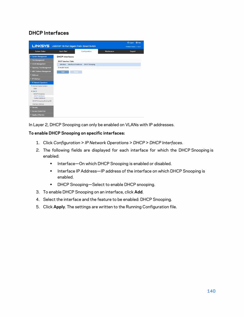
140
DHCP Interfaces
In Layer 2, DHCP Snooping can only be enabled on VLANs with IP addresses.
To enable DHCP Snooping on specific interfaces:
1. Click Configuration > IP Network Operations > DHCP > DHCP Interfaces.
2. The following fields are displayed for each interface for which the DHCP Snooping is enabled:
• Interface—On which DHCP Snooping is enabled or disabled.
• Interface IP Address—IP address of the interface on which DHCP Snooping is enabled.
• DHCP Snooping—Select to enable DHCP snooping.
3. To enable DHCP Snooping on an interface, click Add.
4. Select the interface and the feature to be enabled: DHCP Snooping.
5. Click Apply. The settings are written to the Running Configuration file.
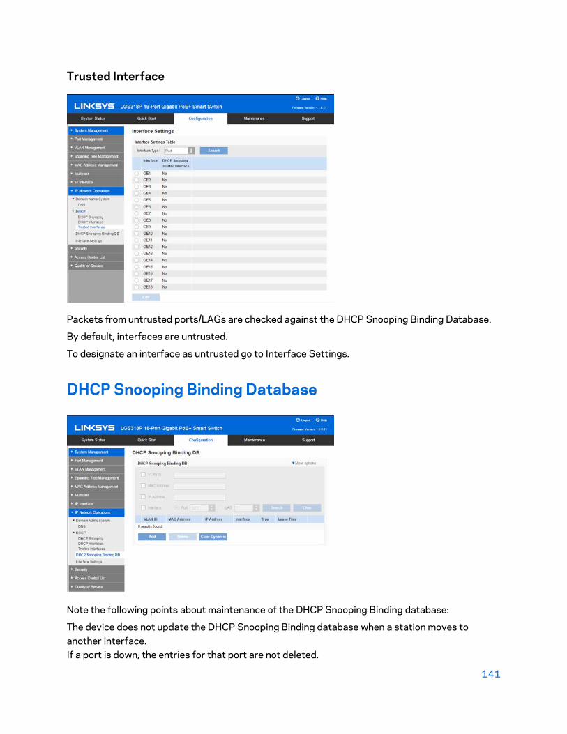
141
Trusted Interface
Packets from untrusted ports/LAGs are checked against the DHCP Snooping Binding Database.
By default, interfaces are untrusted.
To designate an interface as untrusted go to Interface Settings.
DHCP Snooping Binding Database
Note the following points about maintenance of the DHCP Snooping Binding database:
The device does not update the DHCP Snooping Binding database when a station moves to another interface. If a port is down, the entries for that port are not deleted.

142
When DHCP Snooping is disabled for a VLAN, the binding entries that were collected for that VLAN are removed.
If the database is full, DHCP Snooping continues to forward packets, but new entries are not created.
To add entries to the DHCP Snooping Binding database:
1. Click Configuration > IP Network Operations > DHCP Snooping Binding Database.
To see a subset of entries in the DHCP Snooping Binding database, enter the relevant search criteria and click Search.
2. To add an entry, click Add and enter the fields:
• VLAN ID—VLAN on which a packet is expected.
• MAC Address—MAC address of a packet.
• IPv4 Address—IP address of a packet.
• Interface—Type of interface on which a packet is expected.
• Type—The possible field values are the following:
• Dynamic—Entry has limited lease time.
• Static—Entry was statically configured.
• Lease Time—If the entry is dynamic, enter the amount of time that the entry is to be active in the DHCP Database in User Defined. If there is no Lease Time, check Infinite.)
3. Click Apply. The settings are defined, and the device is updated.
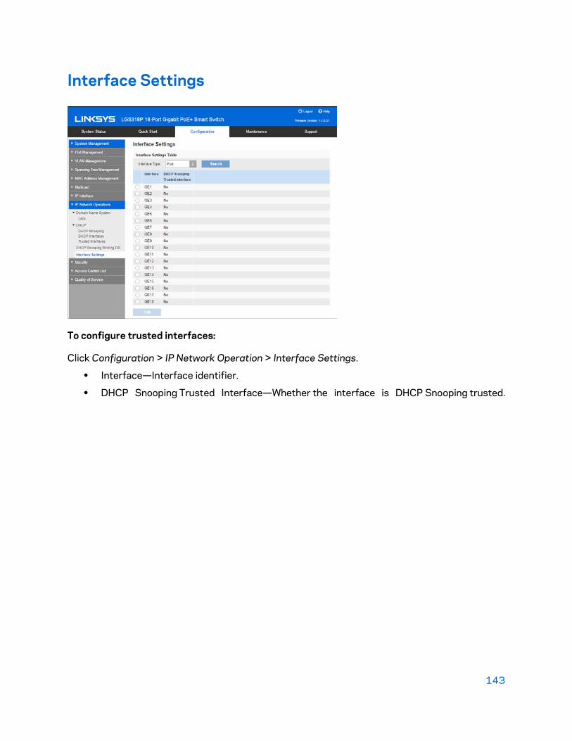
143
Interface Settings
To configure trusted interfaces:
Click Configuration > IP Network Operation > Interface Settings.
• Interface—Interface identifier.
• DHCP Snooping Trusted Interface—Whether the interface is DHCP Snooping trusted.
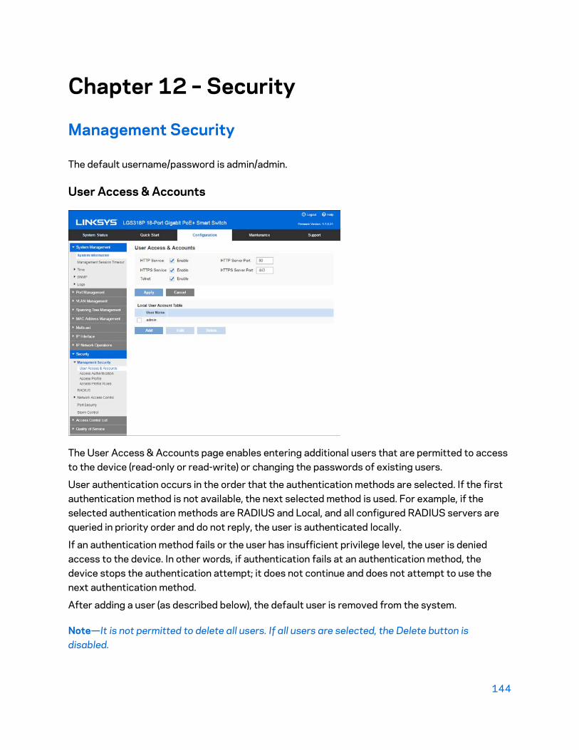
144
Chapter 12 – Security
Management Security
The default username/password is admin/admin.
User Access & Accounts
The User Access & Accounts page enables entering additional users that are permitted to access to the device (read-only or read-write) or changing the passwords of existing users.
User authentication occurs in the order that the authentication methods are selected. If the first authentication method is not available, the next selected method is used. For example, if the selected authentication methods are RADIUS and Local, and all configured RADIUS servers are queried in priority order and do not reply, the user is authenticated locally.
If an authentication method fails or the user has insufficient privilege level, the user is denied access to the device. In other words, if authentication fails at an authentication method, the device stops the authentication attempt; it does not continue and does not attempt to use the next authentication method.
After adding a user (as described below), the default user is removed from the system.
Note—It is not permitted to delete all users. If all users are selected, the Delete button is disabled.

145
To add a new user:
1. Click Configuration > Security > Management Security > User Access & Accounts.
2. Enter the following fields:
• HTTP Service—Select to enable on the device.
• HTTP Server Port—Enter the port on which HTTP is enabled.
• HTTPS Service—Select to enable on the device.
• HTTPS Server Port—Enter the port on which HTTPS is enabled.
• Telnet—Select to enable on the device.
3. Click Add to add a new user or click Edit to modify a user.
4. Enter the parameters.
• User Name—Enter a new username between 0 and 20 characters. UTF-8 characters are not permitted.
• Password—Enter a password (UTF-8 characters are not permitted).
• Confirm Password—Enter the password again.
5. Click Apply. The user is added to the Running Configuration file of the device.
Access Authentication
You can assign authentication methods to the various management access methods, such as console, HTTP, and HTTPS. The authentication can be performed locally or on a RADIUS server.

146
User authentication occurs in the order that the authentication methods are selected. If the first authentication method is not available, the next selected method is used. For example, if the selected authentication methods are RADIUS and Local, and all configured RADIUS servers are queried in priority order and do not reply, the user is authenticated locally.
If an authentication method fails or the user has insufficient privilege level, the user is denied access to the device. If authentication fails at an authentication method, the device stops the authentication attempt; it does not continue and does not attempt to use the next authentication method.
To define authentication methods for an access method:
1. Click Configuration > Security > Management Security > Management Access Authentication.
2. Select an access method from the Application list.
3. Use the arrows to move the authentication method between the Method Available column and the Method To Use column. The first method selected is the first method that is used.
• RADIUS—User is authenticated on a RADIUS server. You must have configured one or more RADIUS servers.
• None—User is allowed to access the device without authentication.
• Local—Username and password are checked against the data stored on the local device. These username and password pairs are defined in the User Accounts page.
Note—The Local or None authentication method must always be selected last. All authentication methods selected after Local or None are ignored.
4. Click Apply. The selected authentication methods are associated with the access method.

147
Access Profile
Access profiles determine how to authenticate and authorize users accessing the device through various access methods. Access profiles can limit management access from specific sources.
Only users who pass both the active access profile and are authorized based on the authentication methods that correspond to the access method are given management access to the device. For more information, see Access Authentication.
There can only be a single access profile active on the device at one time. Access profiles consist of one or more rules. The rules are executed in order of their priority within the access profile (top to bottom).
Rules are composed of filters that include the following elements:
• Access Methods—Methods for accessing and managing the device: The authentication method for the selected access method is specified in Management Access Authentication
o Telnet o Hypertext Transfer Protocol (HTTP) o Secure HTTP (HTTPS) o Simple Network Management Protocol (SNMP) o All of the above
• Action—Permit or deny access to an interface or source address.
• Interface—Which ports, LAGs, or VLANs are permitted to access or are denied access to the web-based configuration utility.
148
• Source IP Address—IP addresses or subnets. Access to management methods might differ among user groups. For example, one user group might be able to access the device module only by using an HTTPS session, while another user group might be able to access the device module by using both HTTPS and Telnet sessions.
The Access Profile page displays the access profiles that are defined and enables selecting one access profile to be the active one.
When a user attempts to access the device through an access method, the device looks to see if the active access profile explicitly permits management access to the device through this method. If no match is found, access is denied.
When an attempt to access the device is in violation of the active access profile, the device generates a SYSLOG message to alert the system administrator of the attempt.
If a console-only access profile has been activated, the only way to deactivate it is through a direct connection from the management station to the physical console port on the device.
Use the Access Profiles page to create an access profile and to add its first rule. If the access profile only contains a single rule, you are finished. To add additional rules to the profile, use the Profile Rules page.
1. Click Configuration > Security > Management Security > Access Profile.
This page displays all of the access profiles, active and inactive.
2. To change the active access profile, select a profile from the Active Access Profile drop down menu and click Apply. This makes the chosen profile the active access profile.
Note—A caution message appears if you selected Console Only. If you continue, you are immediately disconnected from the web-based configuration utility and can access the device only through the console port. This only applies to device types that offer a console port.
3. Click OK to select the active access profile or click Cancel to discontinue the action.
4. Click Add to open the Add Access Profile page. The page allows you to configure a new profile and one rule.
5. Enter the Access Profile Name. This name can contain up to 32 characters.
6. Enter the new rule parameters.
• Rule Priority—Enter the rule priority. When the packet is matched to a rule, user groups are either granted or denied access to the device. The rule priority is essential to matching packets to rules, as packets are matched on a first-match basis. One is the highest priority.
• Management Access Method—Select the management method for which the rule is defined. The options are:
• All—Assigns all management methods to the rule.

149
• Telnet—Users requesting access to the device that meets the Telnet access profile criteria are permitted or denied access.
• HTTP— Users requesting access to the device that meets the HTTP access profile criteria, are permitted or denied.
• Secure HTTP (HTTPS)—Users requesting access to the device that meets the HTTPS access profile criteria, are permitted or denied.
• SNMP—Users requesting access to the device that meets the SNMP access profile criteria are permitted or denied.
• Access Control—Select the action attached to the rule. The options are: o Permit—Permits access to the device if the user matches the settings in
the profile. o Deny—Denies access to the device if the user matches the settings in the
profile.
• Interface—Select the interface attached to the rule. The options are: o All—Applies to all ports, VLANs, and LAGs. o Port—Rule applies to ports. o LAG—Rule applies to LAGs. o VLAN—Rule applies to VLANs.
• Source IP Address—Select the type of source IP address to which the access profile applies. The Source IP Address field is valid for a subnetwork. Select one of the following values:
o All—Applies to all types of IP addresses. o User Defined—Applies to only those types of IP addresses defined in the
fields.
• IP Version—Enter the version of the source IP address: Version 6 or Version 4.
• IP Address—Enter the source IP address.
• IP Subnet Mask—Select the format for the subnet mask for the source IP address, and enter a value in one of the fields:
o Network Mask—Select the subnet to which the source IP address belongs and enter the subnet mask in dotted decimal format.
o Prefix Length—Select the Prefix Length and enter the number of bits that comprise the source IP address prefix.
7. Click Apply. The access profile is written to the Running Configuration file. You can now select this access profile as the active access profile.

150
Access Profile Rules
Access profiles can contain up to 128 rules to determine who is permitted to manage and access the device, and the access methods that may be used.
Each rule in an access profile contains an action and criteria (one or more parameters) to match. Each rule has a priority; rules with the lowest priority are checked first. If the incoming packet matches a rule, the action associated with the rule is performed. If no matching rule is found within the active access profile, the packet is dropped.
For example, you can limit access to the device from all IP addresses except IP addresses that are allocated to the IT management center. In this way, the device can still be managed and has gained another layer of security.
To add profile rules to an access profile:
1. Click Configuration > Security > Management Security > Access Profile Rules.
2. Select the Filter field, and an access profile. Click Search.
The selected access profile appears in the Profile Rule Table.
3. Click Add to add a rule.
4. Enter the parameters.
• Access Profile Name—Select an access profile.
• Rule Priority—Enter the rule priority. When the packet is matched to a rule, user groups are either granted or denied access to the device. The rule priority is essential to matching packets to rules, as packets are matched on a first-fit basis.
• Management Access Method—Select the management method for which the rule is defined. The options are:
151
o All—Assigns all management methods to the rule. o Telnet—Users requesting access to the device that meets the Telnet
access profile criteria are permitted or denied access. o HTTP—Assigns HTTP access to the rule. Users requesting access to the
device that meets the HTTP access profile criteria, are permitted or denied. o Secure HTTP (HTTPS)—Users requesting access to the device that meets
the HTTPS access profile criteria, are permitted or denied. o SNMP—Users requesting access to the device that meets the SNMP
access profile criteria are permitted or denied.
• Access Control—Select Permit to permit the users that attempt to access the device by using the configured access method from the interface and IP source defined in this rule. Or select Deny to deny access.
• Interface—Select the interface attached to the rule. The options are: o All—Applies to all ports, VLANs, and LAGs. o Port—Select the port attached to the rule. o LAG—Select the LAG attached to the rule. o VLAN—Select the VLAN attached to the rule.
• Source IP Address—Select the type of source IP address to which the access profile applies. The Source IP Address field is valid for a subnetwork. Select one of the following values:
o All—Applies to all types of IP addresses. o User Defined—Applies to only those types of IP addresses defined in the
fields.
• IP Version—Select the supported IP version of the source address: IPv6 or IPv4.
• IP Address—Enter the source IP address.
• IP Subnet Mask—Select the format for the subnet mask for the source IP address, and enter a value in one of the field:
o Network Mask—Select the subnet to which the source IP address belongs and enter the subnet mask in dotted decimal format.
o Prefix Length—Select the Prefix Length and enter the number of bits that comprise the source IP address prefix.
5. Click Apply, and the rule is added to the access profile.

152
RADIUS
Remote Authorization Dial-In User Service (RADIUS) servers provide a centralized 802.1X network access control. The device is a RADIUS client that can use a RADIUS server to provide centralized security.
An organization can establish a RADIUS server to provide centralized 802.1X network access control for all of its devices. In this way, authentication and authorization can be handled on a single server for all devices in the organization.
The device can act as a RADIUS client that uses the RADIUS server for the following services:
• Authentication—Provides authentication of regular and 802.1X users logging onto the device by using usernames and user-defined passwords.
• Authorization—Performed at login. After the authentication session is completed, an authorization session starts using the authenticated username. The RADIUS server then checks user privileges.
• Accounting—Enable accounting of login sessions using the RADIUS server. This enables a system administrator to generate accounting reports from the RADIUS server.
Accounting Using a RADIUS Server
The user can enable accounting of login sessions using a RADIUS server.
The user-configurable, TCP port used for RADIUS server accounting is the same TCP port that is used for RADIUS server authentication and authorization.

153
Defaults
The following defaults are relevant to this feature:
• No default RADIUS server is defined by default.
• If you configure a RADIUS server, the accounting feature is disabled by default.
To user a RADIUS server:
1. Open an account for the device on the RADIUS server.
2. Configure that server along with the other parameters in the RADIUS and ADD RADIUS Server pages.
Note—If more than one RADIUS server has been configured, the device uses the configured priorities of the available RADIUS servers to select the RADIUS server to be used by the device.
To set the RADIUS server parameters:
1. Click Security > RADIUS.
2. Enter the default RADIUS parameters if required. If a value is not entered for a specific server (in the Add RADIUS Server page) the device uses the values in these fields.
• Retries—Enter the number of transmitted requests that are sent to the RADIUS server before a failure is considered to have occurred.
• Timeout for Reply—Enter the number of seconds that the device waits for an answer from the RADIUS server before retrying the query, or switching to the next server.
• Dead Time—Enter the number of minutes that elapse before a non- responsive RADIUS server is bypassed for service requests. If the value is 0, the server is not bypassed.
• Key String—Enter the default key string used for authenticating and encrypting between the device and the RADIUS server. This key must match the key configured on the RADIUS serve. A key string is used to encrypt communications by using MD5. This overrides the default key string if one has been defined.
3. Click Apply. The RADIUS default settings for the device are updated in the Running Configuration file.
4. To add a RADIUS server, click Add.
5. Enter the values in the fields for each RADIUS server. To use the default values entered in the RADIUS page, select Use Default.
• Add Server—Select whether to specify the RADIUS server by IP address or name.
• IP Version—Select the version of the IP address of the RADIUS server.

154
• IPv6 Address Type—Select the IPv6 address type (if IPv6 is used). The options are: o Link Local—The IPv6 address uniquely identifies hosts on a single network
link. A link local address has a prefix of FE80, is not routable, and can be used for communication only on the local network. Only one link local address is supported. If a link local address exists on the interface, this entry replaces the address in the configuration.
o Global—The IPv6 address is a global Unicast IPV6 type that is visible and reachable from other networks.
o Interface—Select the link local interface (if IPv6 Address Type Link Local is selected) from the list.
• Server IP Address—Enter the IP address of the RADIUS server.
• Server IP Name—Enter the name of the RADIUS server.
• Authentication Port—Enter the UDP port number of the RADIUS server port for authentication requests.
• Accounting Port—Enter the UDP port number of the RADIUS server port for accounting requests.
• Priority—Enter the priority of the server. The priority determines the order the device attempts to contact the servers to authenticate a user. The device starts with the highest priority RADIUS server first. Zero is the highest priority.
• Key String—Enter the key string used for authenticating and encrypting communication between the device and the RADIUS server. This key must match the key configured on the RADIUS server. If Use Default is selected, the device attempts to authenticate to the RADIUS server by using the default Key String.
• Usage Type—Enter the RADIUS server authentication type. The options are: o Login—RADIUS server is used for authenticating users that ask to
administer the device. o 802.1X—RADIUS server is used for 802.1x authentication. o All—RADIUS server is used for authenticating user that ask to administer
the device and for 802.1X authentication.
6. Click Apply. The RADIUS server definition is added to the Running Configuration file of the device.

155
Network Access Control
802.1x authentication restricts unauthorized clients from connecting to a LAN through publicity-accessible ports. 802.1x authentication is a client-server model. In this model, network devices have the following specific roles:
• Client or supplicant
• Authenticator
• Authentication server
This is described in the figure below:
A network device can be either a client/supplicant, an authenticator or both per port.
Client or Supplicant
A client or supplicant is a network device that requests access to the LAN. The client is connected to an authenticator.
If the client uses the 802.1x protocol for authentication, it runs the supplicant part of the 802.1x protocol and the client part of the EAP protocol.
Authenticator
An authenticator is a network device that provides network services and to which supplicant ports are connected.
The following authentication modes on ports are supported:
• Multiple Host (802.1x)—Supports port-based authentication. If one client is authenticated, all client devices attaching to the port have access.
• Multiple Sessions—Supports client-based authentication. Each client must be authenticated individually before receiving access.
See Port Host Modes for more information.
In 802.1x-based authentication, the authenticator extracts the EAP messages from the 802.1x messages (EAPOL frames) and passes them to the authentication server, using the RADIUS protocol.
156
Authentication Server
An authentication server performs the actual authentication of the client. The authentication server for the device is a RADIUS authentication server with EAP extensions.
Port Administrative Authentication States
The port administrative state determines whether the client is granted access to the network.
The port administrative state can be configured in the Port Authentication page. The following values are available:
• Force Authorized Port authentication is disabled and the port transmits all traffic in accordance with its static configuration without requiring any authentication. The switch sends the 802.1x EAP-packet with the EAP success message inside when it receives the 802.1x EAPOL-start message. This is the default state.
• Force Unauthorized Port authentication is disabled and the port transmits all traffic via the guest VLAN. The switch sends 802.1x EAP packets with EAP failure messages inside when it receives 802.1x EAPOL- Start messages.
• Auto Enables 802.1 x authentications in accordance with the configured port host mode and authentication methods configured on the port.
Port Host Modes
Ports can be placed in the following port host modes (configured in the Host Authentication page):
• Multi-Host Mode
A port is authorized if there is at least one authorized client.
When a port is unauthorized and a guest VLAN is enabled, untagged traffic is remapped to the guest VLAN. Tagged traffic is dropped unless it belongs to the guest VLAN.When a port is authorized, untagged and tagged traffic from all hosts connected to the port is bridged, based on the static VLAN membership port configuration.
You can specify that untagged traffic from the authorized port will be remapped to a VLAN that is assigned by a RADIUS server during the authentication process. Tagged traffic is dropped unless it belongs to the RADIUS-assigned VLAN. Radius VLAN assignment on a port is set in the Port Authentication page.
• Multi-Sessions Mode
Unlike multi-host modes, a port in the multi-session mode does not have an authentication status. The maximum number of authorized hosts allowed on the port is configured in the Port Authentication page.
Tagged and untagged traffic from unauthorized hosts is remapped to the guest VLAN if it is defined and enabled on the VLAN, or it is dropped if the guest VLAN is not enabled on the port.
If an authorized host is assigned a VLAN by a RADIUS server, all its tagged and untagged traffic is bridged via the VLAN. If the VLAN is not assigned, all its traffic is bridged based on the static VLAN membership port configuration.

157
Multiple Authentication Methods
If more than one authentication method is enabled on the switch, the following hierarchy of authentication methods is applied:
• 802.1x Authentication: Highest
• MAC-Based Authentication: Lowest
Multiple methods can run at the same time. When one method finishes successfully, the client becomes authorized, the methods with lower priority are stopped and the methods with higher priority continue.
When one of the authentication methods running simultaneously fails, the other methods continue.
When an authentication method finishes successfully for a client authenticated by a method with a lower priority, the attributes of the new method are applied.When the new method fails, the client is left authorized with the old method.
802.1x-Based Authentication
The device supports the 802.1x authentication mechanism, as described in the standard, to authenticate and authorize 802.1x supplicants.
The 802.1x-based authenticator relays transparent EAP messages between
802.1x supplicants and authentication servers. The EAP messages between supplicants and the authenticator are encapsulated into the 802.1x messages, and the EAP messages between the authenticator and authentication servers are encapsulated into the RADIUS messages.
This is described in the following:
MAC-Based Authentication
MAC-based authentication is an alternative to 802.1X authentication that allows network access to devices (such as printers and IP phones) that do not have the 802.1X supplicant capability. MAC-based authentication uses the MAC address of the connecting device to grant or deny network access.
This image cannot currently be displayed.
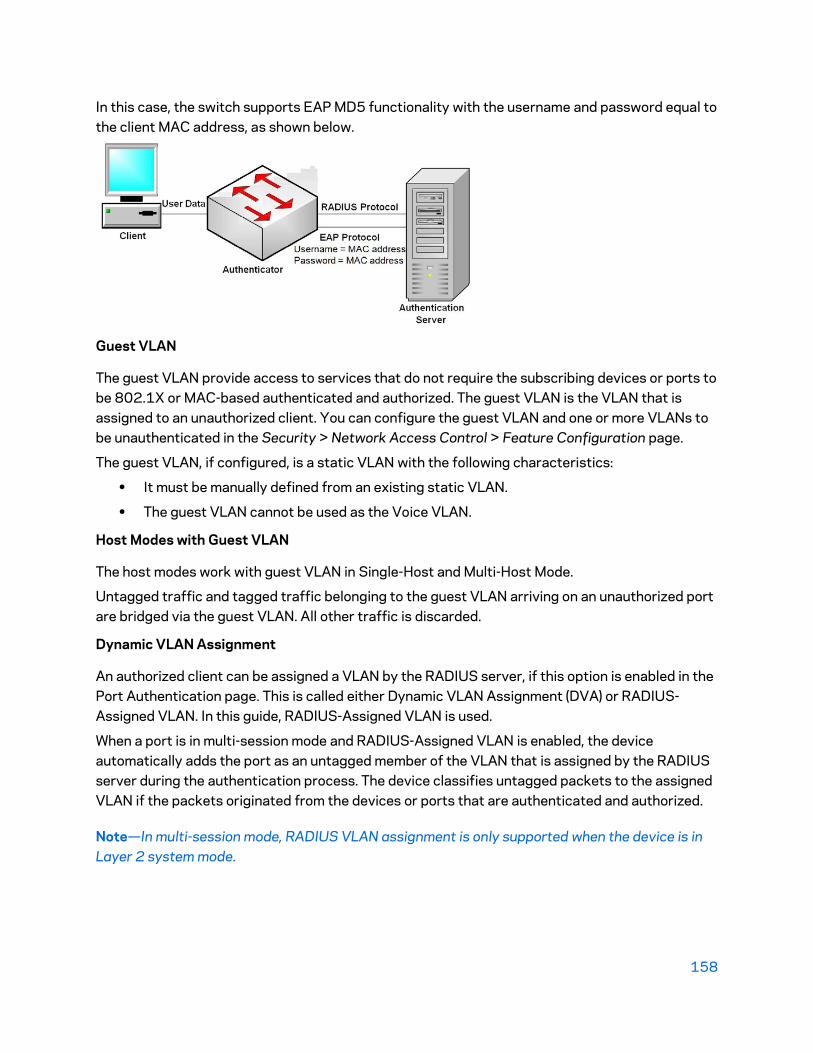
158
In this case, the switch supports EAP MD5 functionality with the username and password equal to the client MAC address, as shown below.
Guest VLAN
The guest VLAN provide access to services that do not require the subscribing devices or ports to be 802.1X or MAC-based authenticated and authorized. The guest VLAN is the VLAN that is assigned to an unauthorized client. You can configure the guest VLAN and one or more VLANs to be unauthenticated in the Security > Network Access Control > Feature Configuration page.
The guest VLAN, if configured, is a static VLAN with the following characteristics:
• It must be manually defined from an existing static VLAN.
• The guest VLAN cannot be used as the Voice VLAN.
Host Modes with Guest VLAN
The host modes work with guest VLAN in Single-Host and Multi-Host Mode.
Untagged traffic and tagged traffic belonging to the guest VLAN arriving on an unauthorized port are bridged via the guest VLAN. All other traffic is discarded.
Dynamic VLAN Assignment
An authorized client can be assigned a VLAN by the RADIUS server, if this option is enabled in the Port Authentication page. This is called either Dynamic VLAN Assignment (DVA) or RADIUS-Assigned VLAN. In this guide, RADIUS-Assigned VLAN is used.
When a port is in multi-session mode and RADIUS-Assigned VLAN is enabled, the device automatically adds the port as an untagged member of the VLAN that is assigned by the RADIUS server during the authentication process. The device classifies untagged packets to the assigned VLAN if the packets originated from the devices or ports that are authenticated and authorized.
Note—In multi-session mode, RADIUS VLAN assignment is only supported when the device is in Layer 2 system mode.

159
When the RADIUS-Assigned VLAN feature is enabled, the host modes behave as follows:
• Single-Host and Multi-Host Mode
Untagged traffic and tagged traffic belonging to the RADIUS-assigned VLAN are bridged via this VLAN. All other traffic not belonging to unauthenticated VLANs is discarded.
• Full Multi-Sessions Mode
Untagged traffic and tagged traffic not belonging to the unauthenticated VLANs arriving from the client are assigned to the RADIUS-assigned VLAN using TCAM rules and are bridged via the VLAN.
Workflow 1: To enable 802.1x authentication on a port
1. Click Configuration > Security > Network AccessControl > Feature Configuration.
2. Enable Port-based Authentication.
3. Select the Authentication Method.
4. Click Apply, and the Running Configuration file is updated.
5. Click Configuration > Security > Network Access Control > Port Authentication.
6. Select the required port and click Edit.
7. Set the Host Authentication mode.
8. Select a port, and click Edit.
9. Set the Administrative Port Control field to Auto.
10. Define the authentication methods.
11. Click Apply, and the Running Configuration file is updated.
Workflow 2: To configure 802.1x-based authentication
1. Click Configuration > Security > Network Access Control > Port Authentication.
2. Select the required port and click Edit.
3. Enter the fields required for the port. The fields in this page are described in Port Authentication.
4. Click Apply, and the Running Configuration file is updated.
Workflow 3: To configure the guest VLAN
1. Click Security > Network Access Control > Feature Configuration.
2. Select Enable in the Guest VLAN field.
3. Select the guest VLAN in the Guest VLAN ID field.
4. Click Apply, and the Running Configuration file is updated.
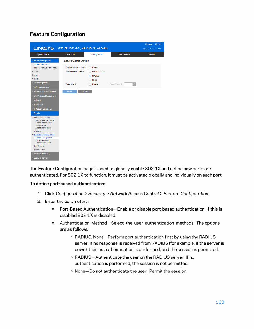
160
Feature Configuration
The Feature Configuration page is used to globally enable 802.1X and define how ports are authenticated. For 802.1X to function, it must be activated globally and individually on each port.
To define port-based authentication:
1. Click Configuration > Security > Network Access Control > Feature Configuration.
2. Enter the parameters:
• Port-Based Authentication—Enable or disable port-based authentication. If this isdisabled 802.1X is disabled.
• Authentication Method—Select the user authentication methods. The optionsare as follows:
o RADIUS, None—Perform port authentication first by using the RADIUSserver. If no response is received from RADIUS (for example, if the server isdown), then no authentication is performed, and the session is permitted.
o RADIUS—Authenticate the user on the RADIUS server. If noauthentication is performed, the session is not permitted.
o None—Do not authenticate the user. Permit the session.
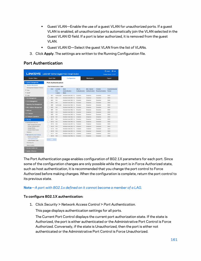
161
• Guest VLAN—Enable the use of a guest VLAN for unauthorized ports. If a guestVLAN is enabled, all unauthorized ports automatically join the VLAN selected in theGuest VLAN ID field. If a port is later authorized, it is removed from the guestVLAN.
• Guest VLAN ID—Select the guest VLAN from the list of VLANs.
3. Click Apply. The settings are written to the Running Configuration file.
Port Authentication
The Port Authentication page enables configuration of 802.1X parameters for each port. Since some of the configuration changes are only possible while the port is in Force Authorized state, such as host authentication, it is recommended that you change the port control to Force Authorized before making changes. When the configuration is complete, return the port control to its previous state.
Note—A port with 802.1x defined on it cannot become a member of a LAG.
To configure 802.1X authentication:
1. Click Security > Network Access Control > Port Authentication.
This page displays authentication settings for all ports.
The Current Port Control displays the current port authorization state. If the state isAuthorized, the port is either authenticated or the Administrative Port Control is ForceAuthorized. Conversely, if the state is Unauthorized, then the port is either notauthenticated or the Administrative Port Control is Force Unauthorized.

162
2. Select a port, and click Edit.
3. Enter the parameters.
• Interface—Select a port.
• Port Control—Select the Administrative Port Authorization state.o Force Unauthorized—Denies the interface access by moving the interface
into the unauthorized state. The device does not provide authenticationservices to the client through the interface.
o Auto—Enables port-based authentication and authorization on the device.The interface moves between an authorized or unauthorized state basedon the authentication exchange between the device and the client.
o Force Authorized—Authorizes the interface without authentication.
• Host Authentication Modeo Multiple Host (802.1x)—Supports port-based authentication with multiple
clients per port.o Multiple Sessions—Supports client-based authentication with multiple
clients per port.
• RADIUS VLAN Assignment—Select to enable Dynamic VLAN assignment on theselected port.
• Guest VLAN—Select to indicate that the usage of a previously-defined guestVLAN is enabled for the device. Enables using a guest VLAN for unauthorizedports. If a guest VLAN is enabled, the unauthorized port automatically joins theVLAN selected in the Guest VLAN ID field in the 802.1X Port Authentication page.
After an authentication failure, and if guest VLAN is activated globally on a givenport, the guest VLAN is automatically assigned to the unauthorized ports as anUntagged VLAN.
• 802.1X Based Authentication—Select to enable 802.1X authentication on theport.
• MAC Based Authentication—Select to enabled MAC-based authentication on theport. The port is authenticated based on the supplicant MAC address. Only 8 MAC-based authentications can be used on the port.
Note—For MAC authentication to succeed, the RADIUS server supplicantusername and password must be the supplicant MAC address. The MAC addressmust be in lower case letters and entered without the . or - separators; forexample: 0020aa00bbcc.
• Period Reauthentication—Select to enable port re-authentication attempts afterthe specified Reauthentication Period.
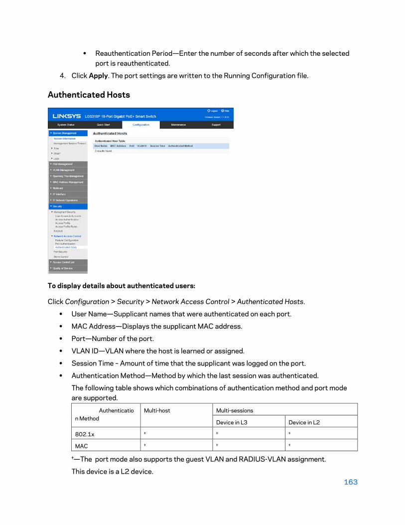
163
• Reauthentication Period—Enter the number of seconds after which the selectedport is reauthenticated.
4. Click Apply. The port settings are written to the Running Configuration file.
Authenticated Hosts
To display details about authenticated users:
Click Configuration > Security > Network Access Control > Authenticated Hosts.
• User Name—Supplicant names that were authenticated on each port.
• MAC Address—Displays the supplicant MAC address.
• Port—Number of the port.
• VLAN ID—VLAN where the host is learned or assigned.
• Session Time – Amount of time that the supplicant was logged on the port.
• Authentication Method—Method by which the last session was authenticated.
The following table shows which combinations of authentication method and port modeare supported.
Authentication Method
Multi-host Multi-sessions
Device in L3 Device in L2
802.1x † † †
MAC † † †
†—The port mode also supports the guest VLAN and RADIUS-VLAN assignment.
This device is a L2 device.

164
Mode Behavior
The following tables describes how authenticated and non-authenticated traffic is handled in various situations.
Unauthenticated Traffic
With Guest VLAN Without Guest VLAN
Untagged Tagged Untagged Tagged
Multi-host Frames are remapped to the guest VLAN
Frames are dropped unless they belong to the guest VLAN or to the unauthenticated VLANs
Frames are dropped Frames are dropped unless they belong to the unauthenticated VLANs
Multi-
session
N/S N/S Frames are dropped Frames are dropped unless they belong to the unauthenticated VLANs
N/S—The authentication method does not support the port mode.
Authenticated Traffic
With RADIUS VLAN Without RADIUS VLAN
Untagged Tagged Untagged Tagged
Multi-host Frames are remapped to the RADIUS VLAN
Frames are dropped unless they belong to the guest RADIUS or unauthenticated VLANs
Frames are bridged based on the static VLAN configuration
Frames are bridged based on the static VLAN configuration
Multi-
session
N/S N/S Frames are bridged based on the
static VLAN configuration
Frames are bridged based on the static VLAN configuration
N/S—The authentication method does not support the port mode.

165
Port Security
Network security can be increased by limiting access on a port to users with specific MAC addresses. The MAC addresses can be either dynamically learned or statically configured.
Port security monitors received and learned packets. Access to locked ports is limited to users with specific MAC addresses.
Port Security has two modes:
• Classic Lock—All learned MAC addresses on the port are locked, and the port does notlearn any new MAC addresses. The learned addresses are not subject to aging orrelearning.
• Limited Dynamic Lock—The device learns MAC addresses up to the configured limit ofallowed addresses. After the limit is reached, the device does not learn additionaladdresses. In this mode, the addresses are subject to aging and relearning.
When a frame from a new MAC address is detected on a port where it is not authorized (the port is classically locked, and there is a new MAC address, or the port is dynamically locked, and the maximum number of allowed addresses has been exceeded), the protection mechanism is invoked, and one of the following actions can take place:
• Frame is discarded
• Frame is forwarded
• Port is shut down
166
To configure port security:
1. Click Configuration > Security > Port Security.
2. Select an interface to be modified, and click Edit.
3. Enter the parameters.
• Interface—Select the interface name.
• Interface Status—Select to lock the port.
• Learning Mode—Select the type of port locking. To configure this field, theInterface Status must be unlocked. The Learning Mode field is enabled only if theInterface Status field is locked. To change the Learning Mode, the Lock Interfacemust be cleared. After the mode is changed, the Lock Interface can be reinstated.
The options:o Classic Lock—Locks the port immediately, regardless of the number of
addresses that have already been learned.o Limited Dynamic Lock—Locks the port by deleting the current dynamic
MAC addresses associated with the port. The port learns up to themaximum addresses allowed on the port. Both relearning and aging of MACaddresses are enabled.
• Maximum Addresses—Enter the maximum number of MAC addresses that can belearned on the port if Limited Dynamic Lock learning mode is selected. The number0 indicates that only static addresses are supported on the interface.
• Action on Violation—Select an action to be applied to packets arriving on a lockedport.
The options:o Discard—Discards packets from any unlearned source.o Forward—Forwards packets from an unknown source without learning the
MAC address.o Shutdown—Discards packets from any unlearned source, and shuts down
the port. The port remains shut down until reactivated, or until the device isrebooted.
• Trap—Enable Trap and set the trap frequency
4. Click Apply. Port security is modified, and the Running Configuration file is updated.

167
Storm Control
When Broadcast, Multicast, or Unknown Unicast frames are received, they are duplicated, and a copy is sent to all possible egress ports. This means that in practice they are sent to all ports belonging to the relevant VLAN. In this way, one ingress frame is turned into many, creating the potential for a traffic storm.
Storm protection enables you to limit the number of frames entering the device and to define the types of frames that are counted towards this limit.
When the rate of Broadcast, Multicast, or Unknown Unicast frames is higher than the user-defined threshold, frames received beyond the threshold are discarded.
To define Storm Control:
1. Click Configuration > Security > Storm Control.
2. Select a port and click Edit.
• Port—Select the port for which storm control is enabled.
• Storm Control—Select to enable Storm Control.
• Storm Control Mode—Select one of the modes:o Unknown Unicast, Multicast & Broadcast—Counts unknown Unicast,
Broadcast, and Multicast traffic towards the bandwidth threshold.o Multicast & Broadcast—Counts Broadcast and Multicast traffic towards
the bandwidth threshold.o Broadcast Only—Counts only Broadcast traffic towards the bandwidth
threshold.

168
• Storm Control Rate Threshold—Enter the maximum rate at which unknownpackets can be forwarded. The default for this threshold is 10,000 for FE devicesand 100,000 for GE devices.
3. Click Apply. Storm control is modified, and the Running Configuration file is updated.

169
Chapter 13 - Access Control List The Access Control List (ACL) feature is part of the security mechanism. ACLs enable network managers to define patterns (filter and actions) for ingress traffic. Packets, entering the device on a port or LAG with an active ACL, are either admitted or denied entry.
An Access Control List (ACL) is an ordered list of classification filters and actions. Each single classification rule, together with its action, is called an Access Control Element (ACE).
Each ACE is made up of filters that distinguish traffic groups and associated actions. A single ACL may contain one or more ACEs, which are matched against the contents of incoming frames. Either a DENY or PERMIT action is applied to frames whose contents match the filter.
The device supports a maximum of 256 ACLs, and a maximum of 256 ACEs.
When a packet matches an ACE filter, the ACE action is taken and that ACL processing is stopped. If the packet does not match the ACE filter, the next ACE is processed. If all ACEs of an ACL have been processed without finding a match, and if another ACL exists, it is processed in a similar manner.
Note—If no match is found to any ACE in all relevant ACLs, the packet is dropped (as a default action). Because of this default drop action you must explicitly add ACEs into the ACL to permit the desired traffic, including management traffic, such as Telnet, HTTP or SNMP that is directed to the device itself. For example, if you do not want to discard all the packets that do not match the conditions in an ACL, you must explicitly add a lowest priority ACE into the ACL that permits all the traffic.
If IGMP snooping is enabled on a port bound with an ACL, add ACE filters in the ACL to forward IGMP/MLD packets to the device; otherwise, IGMP snooping fails at the port.
The order of the ACEs within the ACL is significant, since they are applied in a first-fit manner. The ACEs are processed sequentially, starting with the first ACE.
ACLs can be used for security, for example by permitting or denying certain traffic flows.
There can only be one ACL per port.
To associate more than one ACL with a port, a policy with one or more class maps must be used.
The following types of ACLs can be defined (depending on which part of the frame header is examined):
• MAC ACL—Examines Layer 2 fields only, as described in Defining MAC-based ACLs.
• IP ACL—Examines the Layer 3 layer of IP frames, as described in IPv4/IPv6-Based ACLs.
If a frame matches the filter in an ACL, it is defined as a flow with the name of that ACL.
Creating ACLs Workflow
To create ACLs and associate them with an interface: 1. Create one or more of the following types of ACLs:

170
• MAC-based ACL by using the MAC Based ACL page and the MAC Based ACE
page.• IPv4-Based ACL by using the IPv4 Based ACL page and the IPv4 Based ACE page.• IPv6-Based ACL by using the IPv6 Based ACL page and the IPv6 Based ACE page.
2. Associate the ACL with interfaces by using the ACL Binding page.
Modifying ACLs Workflow
An ACL can only be modified if it is not in use.
To unbind an ACL in order to modify it:
1. If the ACL has been associated with an interface, unbind it from the interface using theACL Binding page.
2. If the ACL is part of the class map and not bound to an interface, then it can be modified.
3. If the ACL is part of a class map contained in a policy bound to an interface, you mustperform the chain of unbinding:
• Unbind the policy containing the class map from the interface by using PolicyBinding.
• Delete the class map containing the ACL from the policy using the Configuring aPolicy (Edit).
• Delete the class map containing the ACL, by using Defining Class Mapping page.
• Only then can the ACL be modified, as described in this section.
MAC-Based ACL
MAC-based ACLs are used to filter traffic based on Layer 2 fields. MAC-based ACLs check all frames for a match.

171
MAC-based ACLs are defined in the MAC Based ACL page. The rules are defined in the MAC-Based ACE page. To define a MAC-based ACL:
1. Click Configuration > Access Control List > MAC Based ACL.
This page contains a list of all currently-defined MAC-based ACLs.
2. Click Add.
3. Enter the name of the new ACL in the ACL Name field. ACL names are case-sensitive.
4. Click Apply. The MAC-based ACL is saved to the Running Configuration file.
MAC-Based ACE
To add rules (ACEs) to an ACL:
1. Click Configuration > Access Control List > MAC-based ACE.
2. Select an ACL, and click Search. The ACEs in the ACL are listed.
3. Click Add.
4. Enter the parameters.
• ACL Name—Select the name of the ACL to which an ACE is being added.
• ACE Priority—Enter the priority of the ACE. ACEs with higher priority areprocessed first. One is the highest priority.
• Action on Matched Packets—Select the action taken upon a match.
• The options:o Permit—Forward packets that meet the ACE criteria.o Deny—Drop packets that meet the ACE criteria.o Shutdown—Drop packets that meet the ACE criteria, and disable the port
from where the packets were received. Such ports can be reactivated fromthe Port Settings page.

172
• Destination MAC Address—Select Any if all destination addresses are acceptableor User Defined to enter a destination address or a range of destination addresses.
• Destination MAC Address Value—Enter the MAC address to which the destinationMAC address is to be matched and its mask (if relevant).
• Destination MAC Wildcard Mask—Enter the mask to define a range of MACaddresses. Note that this mask is different than in other uses, such as subnetmask. Here, setting a bit as 1 indicates don’t care and 0 indicates to mask thatvalue.
Note—Given a mask of 0000 0000 0000 0000 0000 0000 1111 1111 (whichmeans that you match on the bits where there is 0 and don’t match on the bitswhere there are 1’s). You need to translate the 1’s to a decimal integer and youwrite 0 for each four zeros. In this example since 1111 1111 = 255, the maskwould be written: as 0.0.0.255.
• Source MAC Address—Select Any if all source address are acceptable or UserDefined to enter a source address or range of source addresses.
• Source MAC Address Value—Enter the MAC address to which the source
• MAC address is to be matched and its mask (if relevant).
• Source MAC Wildcard Mask—Enter the mask to define a range of MAC addresses.
• VLAN ID—Enter the VLAN ID section of the VLAN tag to match.
• 802.1p—Select Match to use 802.1p.
• 802.1p Value—Enter the 802.1p value to be added to the VPT tag.
• 802.1p Mask—Enter the wildcard mask to be applied to the VPT tag.
• EtherType—Enter the frame EtherType to be matched.
5. Click Apply. The MAC-Based ACE is saved to the Running Configuration file.
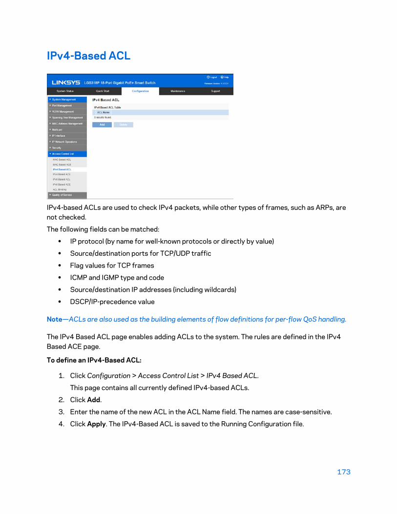
173
IPv4-Based ACL
IPv4-based ACLs are used to check IPv4 packets, while other types of frames, such as ARPs, are not checked.
The following fields can be matched:
• IP protocol (by name for well-known protocols or directly by value)
• Source/destination ports for TCP/UDP traffic
• Flag values for TCP frames
• ICMP and IGMP type and code
• Source/destination IP addresses (including wildcards)
• DSCP/IP-precedence value
Note—ACLs are also used as the building elements of flow definitions for per-flow QoS handling.
The IPv4 Based ACL page enables adding ACLs to the system. The rules are defined in the IPv4 Based ACE page.
To define an IPv4-Based ACL:
1. Click Configuration > Access Control List > IPv4 Based ACL.
This page contains all currently defined IPv4-based ACLs.
2. Click Add.
3. Enter the name of the new ACL in the ACL Name field. The names are case-sensitive.
4. Click Apply. The IPv4-Based ACL is saved to the Running Configuration file.

174
IPv4-Based ACE
To add rules (ACEs) to an IPv4-Based ACL:
1. Click Configuration > Access Control List > IPv4-Based ACE.
2. Select an ACL, and click Search. All currently-defined IP ACEs for the selected ACL aredisplayed.
3. Click Add.
4. Enter the parameters.
• ACL Name—Displays the name of the ACL.
• ACE Priority—Enter the priority. ACEs with higher priority are processed first.
• Action on Match Packets—Select the action assigned to the packet matching theACE.
• The options:o Permit—Forward packets that meet the ACE criteria.o Deny—Drop packets that meet the ACE criteria.o Shutdown—Drop packet that meets the ACE criteria and disable the port
to which the packet was addressed. Ports are reactivated from the PortManagement page.
• Protocol—Select to create an ACE based on a specific protocol or protocol ID.Select Any IPv4 to accept all IP protocols. Otherwise select one of the followingprotocols from the drop-down list:
o ICMP—Internet Control Message Protocolo IGMP—Internet Group Management Protocolo IP in IP—IP in IP encapsulationo TCP—Transmission Control Protocolo UDP—User Datagram Protocol

175
• Protocol ID —Instead of selecting the name, enter the protocol ID.
• Source IP Address—Select Any if all source address are acceptable or UserDefined to enter a source address or range of source addresses.
• Source IP Address Value—Enter the IP address to which the source MAC addressis to be matched and its mask (if relevant).
• Source IP Wildcard Mask—Enter the mask to define a range of IP addresses.Setting a bit as 1 indicates don’t care and 0 indicates to mask that value.
Note—Given a mask of 0000 0000 0000 0000 0000 0000 1111 1111 (whichmeans that you match on the bits where there is 0 and don’t match on the bitswhere there are 1’s). You need to translate the 1’s to a decimal integer and youwrite 0 for each four zeros. In this example since 1111 1111 = 255, the maskwould be written: as 0.0.0.255.
• Destination IP Address—Select Any if all destination address are acceptable orUser Defined to enter a destination address or range of destination addresses.
• Destination IP Address Value—Enter the IP address to which the destination IPaddress is to be matched.
• Destination IP Wildcard Mask—Enter the mask to define a range of IP addresses.
• Source Port—Select one of the following:o Any—Match to all source ports.o Single Port—Enter a single TCP/UDP source port to which packets are
matched. This field is active only if 800/6-TCP or 800/17-UDP is selectedin the Select from List drop-down menu.
• Destination Port—Select one of the available values that are the same as theSource Port field described above.
Note—You must specify the IP protocol for the ACE before you can enter thesource and/or destination port.
• Type of Service—The service type of the IP packet.o Any—Any service typeo DSCP to Match—Differentiated Serves Code Point (DSCP) to matcho IP Precedence to match—IP precedence is a model of TOS (type of service)
that the network uses to help provide the appropriate QoS commitments.This model uses the 3 most significant bits of the service type byte in theIP header, as described in RFC 791 and RFC 1349.
5. Click Apply. The IPv4-Based ACE is saved to the Running Configuration file.
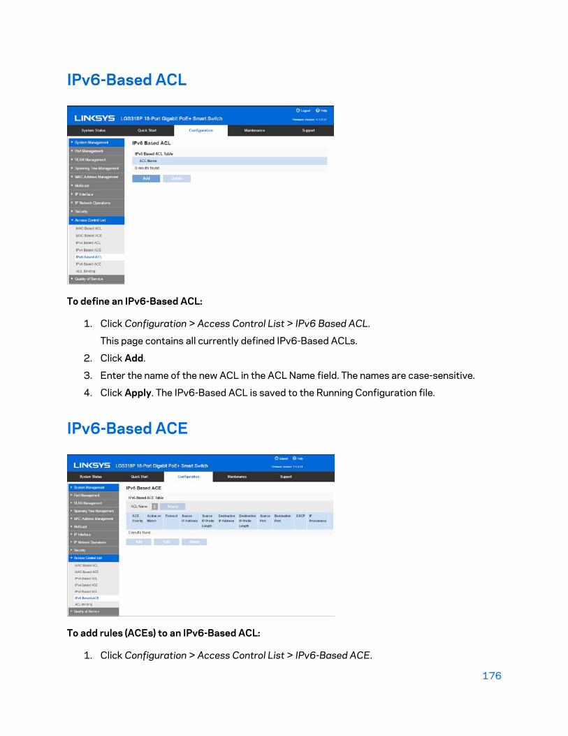
176
IPv6-Based ACL
To define an IPv6-Based ACL:
1. Click Configuration > Access Control List > IPv6 Based ACL.
This page contains all currently defined IPv6-Based ACLs.
2. Click Add.
3. Enter the name of the new ACL in the ACL Name field. The names are case-sensitive.
4. Click Apply. The IPv6-Based ACL is saved to the Running Configuration file.
IPv6-Based ACE
To add rules (ACEs) to an IPv6-Based ACL:
1. Click Configuration > Access Control List > IPv6-Based ACE.

177
2. Select an ACL, and click Search.
All currently-defined IP ACEs for the selected ACL are displayed.
3. Click Add.
4. Enter the parameters.
• ACL Name—Displays the name of the ACL.
• ACE Priority—Enter the priority. ACEs with higher priority are processed first.
• Action on Match Packets—Select the action assigned to the packet matching theACE. The options:
o Permit—Forward packets that meet the ACE criteria.o Deny—Drop packets that meet the ACE criteria.o Shutdown—Drop packet that meets the ACE criteria and disable the port
to which the packet was addressed. Ports are reactivated from the PortManagement page.
• Protocol—Select to create an ACE based on a specific protocol or protocol ID.Select Any IPv6 to accept all IP protocols. Otherwise select one of the followingprotocols from the drop-down list:
o ICMP—Internet Control Message Protocolo TCP—Transmission Control Protocolo UDP—User Datagram Protocol
• Protocol ID—Instead of selecting the name, enter the protocol ID.
• Source IP Address—Select Any if all source addresses are acceptable or UserDefined to enter a source address or range of source addresses.
• Source IP Address Value—Enter the IP address to which the source MAC addressis to be matched and its mask (if relevant).
• Source IP Prefix Length—Enter the prefix length of the source IP address.
• Destination IP Address—Select Any if all destination addresses are acceptable orUser Defined to enter a destination address or range of destination addresses.
• Destination IP Address Value—Enter the IP address to which the destination IPaddress is to be matched.
• Destination IP Prefix Length—Enter the prefix length of the destination IP address.
• Source Port—Select one of the following:o Any—Match to all source ports.o Single Port—Enter a single TCP/UDP source port to which packets are
matched. This field is active only if 800/6-TCP or 800/17-UDP is selectedin the Select from List drop-down menu.
• Destination Port—Select one of the available values that are the same as theSource Port field described above.
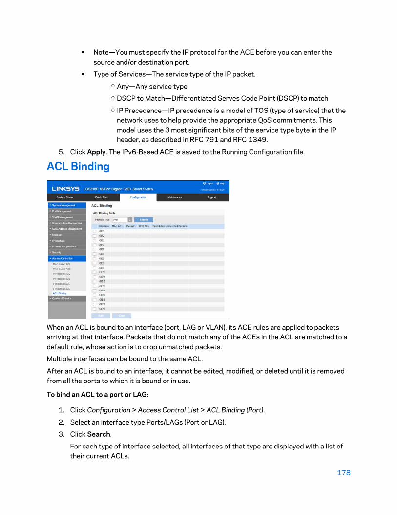
178
• Note—You must specify the IP protocol for the ACE before you can enter thesource and/or destination port.
• Type of Services—The service type of the IP packet.o Any—Any service typeo DSCP to Match—Differentiated Serves Code Point (DSCP) to matcho IP Precedence—IP precedence is a model of TOS (type of service) that the
network uses to help provide the appropriate QoS commitments. Thismodel uses the 3 most significant bits of the service type byte in the IPheader, as described in RFC 791 and RFC 1349.
5. Click Apply. The IPv6-Based ACE is saved to the Running Configuration file.
ACL Binding
When an ACL is bound to an interface (port, LAG or VLAN), its ACE rules are applied to packets arriving at that interface. Packets that do not match any of the ACEs in the ACL are matched to a default rule, whose action is to drop unmatched packets.
Multiple interfaces can be bound to the same ACL.
After an ACL is bound to an interface, it cannot be edited, modified, or deleted until it is removed from all the ports to which it is bound or in use.
To bind an ACL to a port or LAG:
1. Click Configuration > Access Control List > ACL Binding (Port).
2. Select an interface type Ports/LAGs (Port or LAG).
3. Click Search.
For each type of interface selected, all interfaces of that type are displayed with a list oftheir current ACLs.

179
Note—To unbind all ACLs from an interface, select the interface, and click Clear.
4. Select an interface, and click Edit.
5. Select one of the following:
• MAC Based ACL—Select a MAC-based ACL to be bound to the interface.
• IPv4 Based ACL—Select an IPv4-Based ACL to be bound to the interface.
• IPv6 Based ACL—Select an IPv6-Based ACL to be bound to the interface.
• Permit Any Unmatched Packets—Select to enable/disable this action.
6. Click Apply. The ACL binding is modified, and the Running Configuration file is updated.
Note—If no ACL is selected, the ACL(s) that is previously bound to the interface are unbound.

180
Chapter 14 - Quality of Service The Quality of Service feature is applied throughout the network to ensure that network traffic is prioritized according to required criteria and the desired traffic receives preferential treatment.
The QoS feature is used to optimize network performance. It provides classification of incoming traffic to traffic classes, based on attributes, including:
• Device configuration
• Ingress interface
• Packet content
• Combination of these attributes
QoS includes the following:
• Traffic Classification—Classifies each incoming packet as belonging to a specific trafficflow, based on the packet contents and/or the port.
• Assignment to Hardware Queues—Assigns incoming packets to forwarding queues.Packets are sent to a particular queue for handling as a function of the traffic class towhich they belong. See Queue Scheduling.
• Other Traffic Class-Handling Attribute—Applies QoS mechanisms to various classes,including bandwidth management.
QoS Operation
When using the QoS feature, all traffic of the same class receives the same treatment, which consists of a single QoS action of determining the egress queue on the egress port, based on the indicated QoS value in the incoming frame. This is the VLAN Priority Tag (VPT) 802.1p value in Layer 2 and the Differentiated Service Code Point (DSCP) value for IPv4 or Traffic Class (TC) value for IPv6 in Layer 3. When operating in Basic Mode, the device trusts this external assigned QoS value. The external assigned QoS value of a packet determines its traffic class and QoS.
The type of header field to be trusted is entered in the Basic QoS page. For every value of that field, an egress queue is assigned, indicating through which queue the frame is sent, in the CoS/802.1p to Queue page or the DSCP to Queue page (depending on whether the trust mode is CoS/802.1p or DSCP, respectively).
181
QoS Modes
The QoS mode that is selected applies to all interfaces in the system.
• Basic Mode—Class of Service (CoS).
All traffic of the same class receives the same treatment, which is the single QoS action ofdetermining the egress queue on the egress port, based on the indicated QoS value in theincoming frame. This can be the VLAN Priority Tag (VPT) 802.1p value in Layer 2 and theDifferentiated Service Code Point (DSCP) value for IPv4 or Traffic Class (TC) value forIPv6 in Layer 3. When operating in Basic Mode, the device trusts this external assignedQoS value. The external assigned QoS value of a packet determines its traffic class andQoS.
The header field to be trusted is entered in the Basic QoS page. For every value of thatfield, an egress queue is assigned where the frame is sent in the CoS/802.1p to Queuepage or the DSCP to Queue page (depending on whether the trust mode is CoS/802.1p orDSCP, respectively).
• Disable Mode—In this mode all traffic is mapped to a single best effort queue, so that notype of traffic is prioritized over another.
When disabling QoS, the shaper and queue setting (WRR/SP bandwidth setting) are resetto default values. All other user configurations remain intact.
QoS Workflow
To configure general QoS parameters:
1. Choose the QoS mode (Basic, or Disabled by using the Feature Configuration page. Thefollowing steps in the workflow, assume that you have chosen to enable QoS.
2. Assign each interface a default CoS priority by using the Feature Configuration page.
3. Assign the schedule method (Strict Priority or WRR) and bandwidth allocation for WRR tothe egress queues by using the Queue Scheduling page.
4. Set the trusted mode in the Basic QoS page.
5. Designate an egress queue to each IP DSCP/TC value with the DSCP to Queue page. If thedevice is in DSCP trusted mode, incoming IP packets are put into the egress queues basedon their DSCP/TC value.
6. Designate an egress queue to each CoS/802.1p priority. If the device is in CoS/802.1trusted mode, all incoming packets are put into the designated egress queues accordingto the CoS/802.1p priority in the packets. This is done by using the CoS/802.1p to Queuepage.
7. Enter bandwidth and rate limits in the following pages:
• Set egress shaping per queue by using the Egress Shaping page.
• Set ingress rate limit and egress shaping rate per port by using the BandwidthControl page.

182
Feature Configuration
The Feature Configuration page contains fields for setting the QoS mode for the system (Basic, or Disabled, as described in the “QoS Modes” section). In addition, the default CoS priority for each interface can be defined.
To select the QoS mode:
1. Click Configuration > Quality of Service > Feature Configuration.
2. Set the QoS mode. The following options are available:
• Disable—QoS is disabled on the device.
• Basic—QoS is enabled on the device in Basic mode.
3. Select Port/LAG and click Search to display/modify all ports/LAGs on the device and theirCoS information.
The following fields are displayed for all ports/LAGs:
• Interface—Type of interface.
• Default CoS—Default VPT value for incoming packets that do not have a VLANTag. The default CoS is 0. The default is only relevant for untagged frames andonly if the system is in Basic mode and Trust CoS is selected in the Basic QoSpage.
4. Click Apply. The Running Configuration file is updated.
To set QoS on an interface:
1. Select an interface, and click Edit.

183
2. Enter the parameters.
• Interface—Select the port or LAG.
• Default CoS—Select the default CoS (Class-of-Service) value to be assigned forincoming packets (that do not have a VLAN tag).
3. Click Apply. The interface default CoS value is saved to Running Configuration file.
Queue Scheduling
The device supports 4 queues for each interface. Queue number four is the highest priority queue. Queue number one is the lowest priority queue.
There are two ways of determining how traffic in queues is handled:
• Strict Priority—Egress traffic from the highest-priority queue is transmitted first. Trafficfrom the lower queues is processed only after the highest queue has been transmitted,thus providing the highest level of priority of traffic to the highest numbered queue.
• Weighted Round Robin (WRR)—In WRR mode, the number of packets sent from the queueis proportional to the weight of the queue (the higher the weight the more frames are sent).For example, if there are a maximum of four queues possible and all four queues are WRRand the default weights are used, queue 1 receives 1/15 of the bandwidth (assuming allqueues are saturated and there is congestion), queue 2 receives 2/15, queue 3 receives4/15 and queue 4 receives 8 /15 of the bandwidth. The type of WRR algorithm used in thedevice is not the standard Deficit WRR (DWRR), but rather Shaped Deficit WRR (SDWRR).
The queuing modes can be selected in the Queue Scheduling page. When the queuing mode is by strict priority, the priority sets the order in which queues are serviced, starting with Queue 4 (the highest priority queue) and going to the next lower queue when each queue is completed.
When the queuing mode is Weighted Round Robin, queues are serviced until their quota has been used up and then another queue is serviced.

184
It is also possible to assign some of the lower queues to WRR, while keeping some of the higher queues in strict priority. In this case, traffic for the strict priority queues is always sent before traffic from the WRR queues. Only after the strict priority queues have been emptied is traffic from the WRR queues forwarded. (The relative portion from each WRR queue depends on its weight).
To select the priority method and enter WRR data:
1. Click Configuration > Quality of Service > Queue Scheduling.
2. Enter the parameters.
• Queue—Displays the queue number.
• Scheduling Method: Select one of the following options:o Strict Priority—Traffic scheduling for the selected queue and all higher
queues is based strictly on the queue priority.o WRR—Traffic scheduling for the selected queue is based on WRR. The
period time is divided between the WRR queues that are not empty,meaning they have descriptors to egress. This happens only if strict priorityqueues are empty.
o WRR Weight—If WRR is selected, enter the WRR weight assigned to thequeue.
o % of WRR Bandwidth—Displays the amount of bandwidth assigned to thequeue. These values represent the percent of the WRR weight.
3. Click Apply. The queues are configured, and the Running Configuration file is updated.
CoS/802.1p to Queue

185
The CoS/802.1p to Queue page maps 802.1p priorities to egress queues. The CoS/802.1p to Queue Table determines the egress queues of the incoming packets based on the 802.1p priority in their VLAN Tags. For incoming untagged packets, the 802.1p priority is the default CoS/802.1p priority assigned to the ingress ports.
The following table describes the default mapping:
802.1p Values (0-7, 7 being the highest)
Queue (4 queues 1-4, 4 being the highest priority)
Notes
0 1 Background
1 1 Best Effort
2 2 Excellent Effort
3 3 Critical Application VoIP phone SIP
4 3 Video
5 4 Voice Cisco IP phone default
6 4 Interwork Control VoIP phone RTP
7 4 Network Control
By changing the CoS/802.1p to Queue mapping (CoS/802.1p to Queue page), the Queue schedule method (Queue Scheduling page) and bandwidth allocation (Bandwidth page), it is possible to achieve the desired quality of service in a network.
The CoS/802.1p to Queue mapping is applicable only if one of the following exists:
• The device is in QoS Basic mode and CoS/802.1p trusted mode
• Queue 1 has the lowest priority; queue 4 has the highest priority.
To map CoS /802.1p values to egress queues:
1. Click Configure> Quality of Service > CoS/802.1p to Queue.
2. Enter the parameters.
• 802.1p—Displays the 802.1p priority tag values to be assigned to an egressqueue, where 0 is the lowest and 7 is the highest priority.
• Output Queue—Select the egress queue to which the 802.1p priority is mapped.Either four or eight egress queues are supported, where Queue 4 is the highestpriority egress queue and Queue 1 is the lowest priority.
3. For each 802.1p priority, select the Output Queue to which it is mapped.
4. Click Apply. 801.1p priority values to queues are mapped, and the Running Configurationfile is updated.

186
DSCP to Queue
The DSCP (IP Differentiated Services Code Point) to Queue page maps DSCP values to egress queues. The DSCP to Queue Table determines the egress queues of the incoming IP packets based on their DSCP values. The original VPT (VLAN Priority Tag) of the packet is unchanged.
By simply changing the DSCP to Queue mapping and the Queue schedule method and bandwidth allocation, it is possible to achieve the desired quality of services in a network.
The DSCP to Queue mapping is applicable to IP packets if the device is in QoS Basic mode and DSCP is the trusted mode. Non-IP packets are always classified to the best-effort queue.
The following tables describe the default DSCP to queue mapping:
DSCP 63 55 47 39 31 23 15 7
Queue 3 3 4 3 3 2 1 1
DSCP 62 54 46 (EF) 38 (AF3) 30 (AF33) 22(AF23) 14 6
Queue 3 3 4 3 3 2 1 1
DSCP 61 53 45 37 29 21 13 5
Queue 3 3 4 3 3 2 1 1
DSCP 60 52 44 36(AF42) 28(AF32) 20(AF22) 12(AF12) 4
Queue 3 3 4 3 3 2 1 1
DSCP 59 51 43 35 27 19 11 3
Queue 3 3 4 3 3 2 1 1
DSCP 58 50 42 34(AF41) 26(AF31) 18(AF21) 10(AF11) 2
Queue 3 3 4 3 3 2 1 1
DSCP 57 49 41 33 25 17 9 1
Queue 3 3 4 3 3 2 1 1
DSCP 56(CS7) 48(CS6) 40(CS5) 32(CS4) 24(CS3) 16(CS2) 8(CS1) 0(BE)
Queue 3 3 4 3 3 2 1 1
The queue 4 is the highest queue and the default classes in the parentheses are defined by IETF.

187
To map DSCP to queues:
1. Click Configuration > Quality of Service > DSCP to Queue.
2. Select the Output Queue (traffic forwarding queue) to which the DSCP value is mapped.
3. Click Apply. The Running Configuration file is updated.
Bandwidth Control
The Bandwidth Control page enables users to define two values, Ingress Rate Limit and Egress Shaping Rate, which determine how much traffic the system can receive and send.
The ingress rate limit is the number of bits per second that can be received from the ingress interface. Excess bandwidth above this limit is discarded.
The following values are entered for egress shaping:
• Committed Information Rate (CIR) sets the average maximum amount of data allowed tobe sent on the egress interface, measured in bits per second.
• Committed Burst Size (CBS) is the burst of data that is allowed to be sent, even though itis above the CIR. This is defined in number of bytes of data.
To enter bandwidth limitation:
1. Click Configuration > Quality of Service > Configure > Bandwidth Control.
The Bandwidth page displays bandwidth information for each interface.
2. Select an interface, and click Edit.
3. Select the Port or LAG interface.
4. Enter the fields for the selected interface:

188
• Ingress Rate Control—Select to enable the ingress rate limit, which is defined inthe field below.
• Ingress Rate Limit—Enter the maximum amount of bandwidth allowed on theinterface.
• Ingress Committed Burst Size—Enter the maximum burst size of data for theingress interface in bytes of data. This amount can be sent even if it temporarilyincreases the bandwidth beyond the allowed limit. This field is only available if theinterface is a port.
Note—The above Ingress Rate Limit fields do not appear when the interface typeis LAG.
• Egress Shaping Control—Select to enable egress shaping on the interface.
• Egress Committed Information Rate—Enter the maximum bandwidth for theegress interface.
• Egress Committed Burst Size (CBS)—Enter the maximum burst size of data for theegress interface in bytes of data. This amount can be sent even if it temporarilyincreases the bandwidth beyond the allowed limit.
5. Click Apply. The bandwidth settings are written to the Running Configuration file.
Egress Shaping
In addition to limiting transmission rate per port, which is done in the Bandwidth page, the device can limit the transmission rate of selected egressing frames on a per-queue basis. Egress rate limiting is performed by shaping the output load.
The device limits all frames except for management frames. Any frames that are not limited are ignored in the rate calculations, meaning that their size is not included in the limit total.
Per-queue Egress rate shaping can be disabled.

189
To define egress shaping per queue:
1. Click Configuration > Quality of Service > Egress Shaping.
The Egress Shaping page displays the rate limit and burst size for each queue.
2. Select an interface type (Port or LAG), and click Search.
3. Select a Port/LAG, and click Edit.
This page enables shaping the egress for up to four queues on each interface.
4. Select the Interface.
5. For each queue that is required, enter the following fields:
• Queue x—Select to enable egress shaping on queue number x.
• Committed Information Rate—Enter the maximum rate (CIR) in Kbits per second(Kbps). CIR is the average maximum amount of data that can be sent.
• Committed Burst Size—Enter the maximum burst size (CBS) in bytes. CBS is themaximum burst of data allowed to be sent even if a burst exceeds CIR.
6. Click Apply. The bandwidth settings are written to the Running Configuration file.
Basic QoS
In QoS Basic mode, a specific domain in the network can be defined as trusted. Within that domain, packets are marked with 802.1p priority and/or DSCP to signal the type of service they require. Nodes within the domain use these fields to assign the packet to a specific output queue. The initial packet classification and marking of these fields is done in the ingress of the trusted domain.
190
To configure Basic QoS mode:
1. Select Basic mode for the system by using the Feature Configuration page.
2. Select the trust-behavior using the Basic QoS page. The device supports CoS/802.1ptrusted mode and DSCP trusted mode. CoS/802.1p trusted mode uses the 802.1ppriority in the VLAN tag. DSCP trusted mode use the DSCP value in the IP header.
In Basic QoS Mode, it is recommended that you disable the trusted mode at the ports where the CoS/802.1p and/or DSCP values of the incoming packets are not trustworthy. Otherwise, it might negatively affect the performance of your network. Incoming packets from ports that are disabled without trust mode are forwarded in best effort.
Basic QoS
The Basic QoS page contains information for enabling Trust on the device.
This configuration is only active when the QoS mode is Basic mode. Packets entering a QoS domain are classified at the edge of the QoS domain.
To define the Trust configuration:
1. Click Configuration > Quality of Service > Basic QoS.
2. Select the Trust Mode while the device is in Basic mode. The Trust mode determines thequeue to which the packet is assigned:
• CoS/802.1p—Traffic is mapped to queues based on the VPT field in the VLAN tag,or based on the per-port default CoS/802.1p value (if there is no VLAN tag on theincoming packet), the actual mapping of the VPT to queue can be configured in themapping CoS/802.1p to Queue page.
• DSCP—All IP traffic is mapped to queues based on the DSCP field in the IP header.The actual mapping of the DSCP to queue can be configured in the DSCP to Queuepage. If traffic is not IP traffic, it is mapped to the best effort queue.
• CoS/802.1p-DSCP—All IP traffic is mapped to queues based on the values in theirDSCP field. All non IP traffic is mapped to queues based on the their CoS/802.1pvalue.
To disable QoS on a port, click Edit, select a port or LAG, deselect Enable QoS.
3. Click Apply. The Running Configuration file is updated with the new settings.

191
QoS Statistics
Queues Statistics
The Queues Statistics page displays queue statistics, including statistics of forwarded and dropped packets, based on interface, queue, and drop precedence.
To view Queues Statistics:
1. Click Configuration > Quality of Service > QoS Statistics > Queues Statistics.
This page displays the following fields:
• Refresh Rate—Select the time period that passes before the interface Ethernetstatistics are refreshed.
The available options:o No Refresh—Statistics are not refreshed.o 15 Sec—Statistics are refreshed every 15 seconds.o 30 Sec—Statistics are refreshed every 30 seconds.o 60 Sec—Statistics are refreshed every 60 seconds.
• Counter Set
The available options:o Set 1—Displays the statistics for Set 1 that contains all interfaces and
queues with a high DP (Drop Precedence).o Set 2—Displays the statistics for Set 2 that contains all interfaces and
queues with a low DP.
• Interface—Queue statistics are displayed for this interface.

192
• Queue—Packets were forwarded or tail dropped from this queue.
• Drop Precedence—Lowest drop precedence has the lowest probability of beingdropped.
• Total Packets—Number of packets forwarded or tail dropped.
• Tail Drop Packets—Percentage of packets that were tail dropped.
2. Click Add.
3. Enter the parameters.
• Counter Set—Select the counter set.o Set 1—Displays the statistics for Set 1 that contains all interfaces and
queues with a high DP (Drop Precedence).o Set 2—Displays the statistics for Set 2 that contains all interfaces and
queues with a low DP.
• Interface—Select the ports for which statistics are displayed.o Port—Selects the port on the selected unit number for which statistics are
displayed.o All Ports—Specifies that statistics are displayed for all ports.
• Queue—Select the queue for which statistics are displayed.
• Drop Precedence—Enter drop precedence that indicates the probability of beingdropped.
4. Click Apply. The Queue Statistics counter is added, and the Running Configuration file isupdated.

193
Chapter 15 - Maintenance All models can be fully managed through the web-based switch configuration utility. GE is the naming convention used for Gigabit Ethernet (10/100/1000) ports.
In Layer 2 system mode, the device forwards packets as a VLAN-aware bridge.
Reboot
Some configuration changes, such as enabling jumbo frame support, require the system to be rebooted before they take effect. However, rebooting the device deletes the Running Configuration, so it is critical that the Running Configuration is saved to the Startup Configuration before the device is rebooted.
Restore to Factory Defaults
Select to reboot the device by using the factory default configuration. This process erases the Startup Configuration file and the backup configuration file.
File Management
System files are files that contain configuration information, firmware images or boot code.
Various actions can be performed with these files, such as selecting the firmware file from which the device boots, copying various types of configuration files internally on the device, or copying files to or from an external device, such as an external server.
Possible methods of file transfer:
• Internal copy
• HTTP/HTTPS that uses the facilities that the browser provides
• TFTF client, requiring a TFTP server
Configuration files on the device are defined by their type, and contain the settings and parameter values for the device. When a configuration is referenced on the device, it is referenced by its configuration file type (such as Startup Configuration or Running Configuration), as opposed to a file name that can be modified by the user.

194
Content can be copied from one configuration file type to another, but the names of the file types cannot be changed by the user.
Other files on the device include firmware, boot code, and log files, and are referred to as operational files.
The configuration files are text files and can be edited in a text editor, such as Notepad after they are copied to an external device, such as a PC.
Files and File Types
The following types of configuration and operational files are found on the device:
• Running Configuration—Contains the parameters currently being used by the device tooperate. This is the only file type that is modified when you change parameter values onthe device.
If the device is rebooted, the Running Configuration is lost. The Startup Configuration,stored in flash memory, overwrites the Running Configuration, stored in RAM.
To preserve any changes you made to the device, you must save the RunningConfiguration to the Startup Configuration, or another file type.
• Startup Configuration—The parameter values that were saved by copying anotherconfiguration (usually the Running Configuration) to the Startup Configuration.
The Startup Configuration is retained in flash memory and is preserved when the device isrebooted. At this time, the Startup Configuration is copied to RAM and identified as theRunning Configuration.
• Backup Configuration—A manual copy of a configuration file used for protection againstsystem shutdown or for the maintenance of a specific operating state. You can copy theStartup Configuration, or Running Configuration to a Backup Configuration file. TheBackup Configuration exists in flash memory and is preserved if the device is rebooted.
• Firmware—The program that controls the operations and functionality of the device. Morecommonly referred to as the image.
• Boot Code—Controls the basic system startup and launches the firmware image.
• Flash Log—SYSLOG messages stored in Flash memory.
File Actions
The following actions can be performed to manage firmware and configuration files:
• Upgrade the firmware or boot code as described in Overview section.
• View the firmware image currently in use or select the image to be used in the next rebootas described in the Active Firmware Image section.
• Save configuration files on the device to a location on another device as described in theConfiguration & Log section.
• Copy one configuration file type to another configuration file type as described in theConfiguration File Copy section.
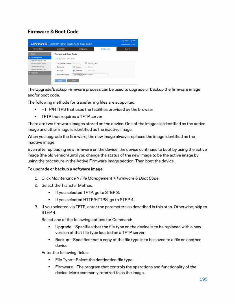
195
Firmware & Boot Code
The Upgrade/Backup Firmware process can be used to upgrade or backup the firmware image and/or boot code.
The following methods for transferring files are supported:
• HTTP/HTTPS that uses the facilities provided by the browser
• TFTP that requires a TFTP server
There are two firmware images stored on the device. One of the images is identified as the active image and other image is identified as the inactive image.
When you upgrade the firmware, the new image always replaces the image identified as the inactive image.
Even after uploading new firmware on the device, the device continues to boot by using the active image (the old version) until you change the status of the new image to be the active image by using the procedure in the Active Firmware Image section. Then boot the device.
To upgrade or backup a software image:
1. Click Maintenance > File Management > Firmware & Boot Code.
2. Select the Transfer Method.
• If you selected TFTP, go to STEP 3.
• If you selected HTTP/HTTPS, go to STEP 4.
3. If you selected via TFTP, enter the parameters as described in this step. Otherwise, skip toSTEP 4.
Select one of the following options for Command:
• Upgrade—Specifies that the file type on the device is to be replaced with a newversion of that file type located on a TFTP server.
• Backup—Specifies that a copy of the file type is to be saved to a file on anotherdevice.
Enter the following fields:
• File Type—Select the destination file type:
• Firmware—The program that controls the operations and functionality of thedevice. More commonly referred to as the image.

196
• Boot Code—Controls the basic system startup and launches the firmware image.
• Source File Name—Enter the name of the source file.
• TFTP Server—Select whether to specify the TFTP server by IP address or domainname.
• IP Version—Select whether an IPv4 or an IPv6 address is used.
• IPv6 Address Type—Select the IPv6 address type (if IPv6 is used). The options areas follows:
o Link Local—The IPv6 address uniquely identifies hosts on a single networklink. A link local address has a prefix of FE80, is not routable, and can beused for communication only on the local network. Only one link localaddress is supported. If a link local address exists on the interface, thisentry replaces the address in the configuration.
o Global—The IPv6 address is a global Unicast IPV6 type that is visible andreachable from other networks.
o Interface—Select the link local interface (if IPv6 is used) from the list.
• TFTP Server IP Address—Enter the IP address of the TFTP server.
• TFTP Server Name—Enter the domain name of the TFTP server.
4. If you selected via HTTP/HTTPS, you can only upgrade.
Click Browse to select a file or enter the path and source file name to be used in thetransfer.
5. Click Apply.
Note—When the process is complete, the following information is displayed.
• Bytes Transferred—How many bites were transferred in the process.
• Status—Did the process succeed or fail.
• Error Message—Reason for failure of the process.

197
Active Firmware Image
There are two firmware images stored on the device. One of the images is identified as the active image and the other image is identified as the inactive image. The device boots from the image you set as the active image. You can change the image identified as the inactive image to the active image.
To select the active image:
1. Click Maintenance > File Management > Active Firmware Image.
• Active Firmware Image—Displays the image file that is currently active on thedevice.
• Version—Displays the firmware version of the active image.
• Active Firmware Image After Reboot—Displays the image that is active afterreboot.
• Version—Displays the firmware version of the active image as it will be afterreboot.
2. Select the image from the Active Firmware Image After Reboot menu to identify thefirmware image that is used as the active image after the device is rebooted. The versionnumber associated with it displays the firmware version of the active image that is usedafter the device is rebooted.
3. Click Apply. The active image selection is updated.

198
Configuration & Log
The Configuration & Log (Backup & Download) page enables:
• Backing up configuration files or logs from the device to an external device.
• Restoring configuration files from an external device to the device.
When restoring a configuration file to the Running Configuration, the imported file adds any configuration commands that did not exist in the old file and overwrites any parameter values in the existing configuration commands.
When restoring a configuration file to the Startup Configuration or a backup configuration file, the new file replaces the previous file.
When restoring to Startup Configuration, the device must be rebooted for the restored Startup Configuration to be used as the Running Configuration.
You can reboot the device by using the process described in the Management Interface section.
To backup or restore the system configuration file:
1. Click Maintenance > File Management > Configuration & Log.
2. Select the File Transfer Protocol.
3. If you selected via TFTP, enter the parameters. Otherwise, skip to STEP 4.
Enter the following fields:
• Commando Download—Specifies that the file on another device upgrades a file type on
the device.o Backup—Specifies that a file is to be copied to a file on another device.
• Source File Name—Enter the source file name for download. File names cannotcontain slashes (\ or /), cannot start with a period (.), and must include between 1and 160 characters. (Valid characters: A-Z, a-z, 0-9, “.”,“-”, “_”).
• Destination File —Select one of the files displayed as the file to be upgraded. Onlyvalid file types are displayed. (The file types are described in the Files and FileTypes section).
199
• TFTP Server—Select whether to specify the TFTP server by IP address or domainname.
• IP Version—Select whether an IPv4 or an IPv6 address is used.
• IPv6 Address Typeo Link Local—The IPv6 address uniquely identifies hosts on a single network
link. A link local address has a prefix of FE80, is not routable, and can beused for communication only on the local network. Only one link localaddress is supported. If a link local address exists on the interface, thisentry replaces the address in the configuration.
o Global—The IPv6 address is a global Unicast IPV6 type that is visible andreachable from other networks.
o Interface—Select the link local interface (if IPv6 is used) from the list.
• TFTP Server IP Address—Enter the IP address of the TFTP server.
• TFTP Server Name—Enter the domain name of the TFTP server.
Note—If the server is selected by name in the Server Definition, there is no need toselect the IP version-related options.
4. Click Apply. The file is upgraded or backed up.
5. If you selected via HTTP/HTTPS, enter the parameters as described in this step.
• Command—Select one of the following options:o Download— Transfer the source file of the local device to the destination
file on this switch.o Backup— Transfer the source file to the local device.
• Source File Name—Enter the file name for download.
• Destination File—Select the configuration file type to be downloaded to.
Only valid file types are displayed. (The file types are described in the Files and FileTypes section).
6. Click Apply. The file is upgraded or backed up.
Note—When the process initiated is completed, the following information is displayed:
• Bytes Transferred—How many bites were transferred in the process.
• Status—Did the process succeed or fail.
• Error Message—Reason for failure of the process.

200
Configuration File Copy
When you click Apply on any window, changes that you made to the device configuration settings are stored only in the Running Configuration. To preserve the parameters in the Running Configuration, the Running Configuration must be copied to another configuration type or saved on another device.
CAUTION—Unless the Running Configuration is copied to the Startup Configuration or another configuration file, all changes made since the last time the file was copied are lost when the device is rebooted.
The following combinations of copying internal file types are allowed:
• From the Running Configuration to the Startup Configuration or Backup Configuration.
• From the Startup Configuration to the Running Configuration or Backup Configuration.
• From the Backup Configuration to the Running Configuration, Startup Configuration.
To copy one type of configuration file to another type of configuration file:
1. Click Maintenance > File Management > Configuration File Copy.
2. Select the Source File to be copied. Only valid file types are displayed (described in theFiles and File Types section).
3. Select the Destination File to be overwritten by the source file.
4. Click Apply. The file is copied.

201
Diagnostics
Copper Test
The Copper Test page displays the results of integrated cable tests performed on copper cables by the Virtual Cable Tester (VCT).
VCT performs two types of tests:
• Time Domain Reflectometry (TDR) technology tests the quality and characteristics of acopper cable attached to a port. Cables of up to 140 meters long can be tested. Theseresults are displayed in the Test Results block of the Copper Test page.
• DSP-based tests are performed on active GE links to measure cable length. These resultsare displayed in the Advanced Information block of the Copper Test page.
Preconditions to Running the Copper Port Test
Before running the test:
• (Mandatory) Disable Short Reach mode (go to Port Management > Green Ethernet >Properties)
• (Optional) Disable EEE (go to Configuration > Port Management > Green Ethernet >Properties page)
Use a CAT5 data cable when testing cables using (VCT).
Accuracy of the test results can have an error range of +/10 for Advanced Testing and +/2 for basic testing.
CAUTION—When a port is tested, it is set to the Down state and communications are interrupted. After the test, the port returns to the Up state. It is not recommended that you run the copper port test on a port you are using to run the web-based switch configuration utility, because communications with that device are disrupted.

202
To test copper cables attached to ports:
1. Click Maintenance > Diagnostics > Copper Test.
2. Select the port on which to run the test.
3. Click Test.
4. When the message appears, click OK to confirm that the link can go down or Cancel toabort the test.
The following fields are displayed in the Test Results block:
• Test Results—Cable test results. Possible values are:o OK—Cable passed the test.o No Cable—Cable is not connected to the port.o Open Cable—Cable is connected on only one side.o Short Cable—Short circuit has occurred in the cable.o Unknown Test Result—Error has occurred.
• Distance to Fault—Distance from the port to the location on the cable where thefault was discovered.
• Port Operational Status—Displays whether port is up or down.
Note—TDR tests cannot be performed when the port speed is 10Mbit/Sec.
Optical Module Status
The Optical Module Status page displays the operating conditions reported by the SFP (Small Form-factor Pluggable) transceiver. Some information might not be available for SFPs that do not support the digital diagnostic monitoring standard SFF-8472.
To view the results of optical tests:
Click Maintenance > Diagnostics > Optical Module Status.
This page displays the following fields:
• Port—Port number on which the SFP is connected.
• Description—Description of optical transceiver.

203
• Serial Number—Serial number of optical transceiver.
• Data Ready—SFP is operational. Values are True and False
• Loss of Signal—Local SFP reports signal loss. Values are True and False.
• Transmitter Fault—Remote SFP reports signal loss. Values are True, False, and NoSignal (N/S).
• Temperature—Temperature (Celsius) at which the SFP is operating.
Ping
Ping is a utility used to test if a remote host can be reached and to measure the round-trip time for packets sent from the device to a destination device.
Ping operates by sending Internet Control Message Protocol (ICMP) echo request packets to the target host and waiting for an ICMP response, sometimes called a pong. It measures the round-trip time and records any packet loss.
To ping a host:
1. Click Maintenance > Diagnostics > Ping.
2. Configure ping by entering the fields:
• Target—Select whether to specify the source interface by its IP address or name.This field influences the interfaces that are displayed in the Source IP field, asdescribed below.
• IP Version—If the source interface is identified by its IP address, select either IPv4or IPv6 to indicate that it will be entered in the selected format.

204
• IPv6 Address Type—Select Link Local or Global as the type of IPv6 address toenter as the destination IP address.
o Link Local—The IPv6 address uniquely identifies hosts on a single networklink. A link local address has a prefix of FE80, is not routable, and can beused for communication only on the local network. Only one link localaddress is supported. If a link local address exists on the interface, thisentry replaces the address in the configuration.
o Global—The IPv6 address is a global Unicast IPV6 type that is visible andreachable from other networks.
o Interface—If the IPv6 address type is Link Local, select from where it isreceived.
• Target IP Address—Address of the device to be pinged. Whether this is an IPaddress or host name depends on the Host Definition.
• Target Name—Host name of the device to be pinged. Whether this is an IP addressor host name depends on the Host Definition.
• Ping Interval—Length of time the system waits between ping packets. Ping isrepeated the number of times configured in the Number of Pings field, whether theping succeeds or not. Choose to use the default interval or specify your own value.
• Number of Pings—The number of times the ping operation is performed. Choose touse the default or specify your own value.
3. Click Start to ping the host. The ping status appears and another message is added to thelist of messages, indicating the result of the ping operation.
4. View the results of ping in the Ping Result section of the page:
• Result—Success or fail of ping.
• Number of Pings Sent—Numbers of responses sent.
• Number of Ping Responses Received—Numbers of responses received.
• Packets Lost—Numbers of responses not received.
• Minimum Round Trip Time—Minimum time passed between sending of packets andreception of responses.
• Maximum Round Trip Time—Maximum time passed between sending of packetsand reception of responses.
• Average Round Trip Time—Average time passed between sending of packets andreception of responses.

205
Traceroute
Traceroute discovers the IP routes along which packets were forwarded by sending an IP packet to the target host and back to the device. The Traceroute page shows each hop between the device and a target host, and the roundtrip time to each such hop.
1. Click Maintenance > Diagnostics > Traceroute.
2. Configure Traceroute by entering information into the following fields:
• Target—Select whether target hosts are identified by their IP address or name.
• IP Version—If the target host is identified by its IP address, select either IPv4 orIPv6 to indicate that it will be entered in the selected format.
• IPv6 Address Type—Select the IPv6 address type (if IPv6 is used). The options are:o Link Local—The IPv6 address uniquely identifies hosts on a single network
link. A link local address has a prefix of FE80, is not routable, and can beused for communication only on the local network. Only one link localaddress is supported. If a link local address exists on the interface, thisentry replaces the address in the configuration.
o Global—The IPv6 address is a global Unicast IPV6 type that is visible andreachable from other networks.
o Interface—If the IPv6 address type is Link Local, select from where it isreceived.
• Target IP Address—Select the target source interface whose IPv4 address will beused as the source IPv4 address for communication messages. Only the existing IPaddresses of the type specified in the IP Version field will be displayed.
• Target Name—Enter the target host name.
• TTL—Enter the maximum number of hops that Traceroute permits. This is used toprevent a case where the sent frame gets into an endless loop. The Traceroutecommand terminates when the destination is reached or when this value isreached. To use the default value (30), select Use Default.

206
• Timeout—Enter the length of time that the system waits for a frame to returnbefore declaring it lost, or select Use Default.
3. Click Start. The operation is performed.
A page appears showing the Round Trip Time (RTT) and status for each trip in free text containing the following information:
• Index—Displays the number of the hop.
• Host—Displays a stop along the route to the destination.
• Round Trip Time (1-3)—Displays the round trip time in (ms) for the first through thirdframe and the status of the first through third operation.
Port Mirroring
Port mirroring is used on a network device to send a copy of network packets seen on one or multiple device ports, to a network monitoring connection on another port on the device. This is commonly used for network appliances that require monitoring of network traffic, such as an intrusion-detection system. A network analyzer connected to the monitoring port processes the data packets for diagnosing, debugging, and performance monitoring. Up to four sources can be mirrored. This can be any combination of four individual ports.
A packet that is received on a network port assigned to a VLAN that is subject to mirroring is mirrored to the analyzer port even if the packet was eventually trapped or discarded. Packets sent by the device are mirrored when Transmit (Tx) mirroring is activated.
Mirroring does not guarantee that all traffic from the source port(s) is received on the analyzer (destination) port. If more data is sent to the analyzer port than it can support, some data might be lost.
Only one instance of mirroring is supported system-wide. The analyzer port is the same for all the mirrored ports.
To enable mirroring:
1. Click Maintenance > Diagnostics > Port Mirroring.
The following fields are displayed:
• Destination Port—Port to which traffic is to be copied; the analyzer port.

207
• Source Port—Interface, port, from which traffic is sent to the analyzer port.
• Mirror Type—Type of monitoring: incoming to the port (Rx), outgoing from the port(Tx), or both.
• Status— Displays one of the following values:o Active—Both source and destination interfaces are up and forwarding
traffic.o Not Ready—Either source or destination (or both) are down or not
forwarding traffic for some reason.
2. Click Add to add a port to be mirrored.
3. Enter the parameters:
• Destination Port—Select the analyzer port to where packets are copied. A networkanalyzer, such as a PC running Wireshark, is connected to this port. If a port isidentified as an analyzer destination port, it remains the analyzer destination portuntil all entries are removed.
• Source Port—Select the source port from where traffic is to be mirrored.
• Mirror Type—Select whether incoming, outgoing, or both types of traffic aremirrored to the analyzer port. If Port is selected, the options are as follows:
o Rx Only—Port mirroring on incoming packets.o Tx Only—Port mirroring on outgoing packets.o Tx and Rx—Port mirroring on both incoming and outgoing packets.
4. Click Apply. Port mirroring is added to the Running Configuration.

208
Chapter - 16 Support
Click “Get Support” to go to the Linksys Small Business support website. Resources available there include setup help, frequently asked questions, software downloads, live chat with technical support, and community forums.

209
Visit linksys.com/support for award-winning 24/7 technical support.
BELKIN, LINKSYS and many product names and logos are trademarks of the Belkin group of companies. Third-party trademarks mentioned are the property of their respective owners. Licenses and notices for third party software used in this product may be viewed here: http://support.linksys.com/en-us/license. Please contact http://support.linksys.com/en-us/gplcodecenter for questions or GPL source code requests.
© 2017 Belkin International, Inc. and/or its affiliates. All rights reserved.
8820-01844 Rev. C00


