CLS Tangential Feed Granulators Models CLS-810, CLS-814, CLS-819, and CLS-824 Corporate Office: 412.312.6000 l Instant Access 24/7 (Parts and Service): 800.458.1960 l Parts and Service: 814.437.6861 USER GUIDE UGG010/0204 www.conairnet.com
Transcript
CLS Tangential FeedGranulatorsModels CLS-810, CLS-814, CLS-819, and CLS-824
Corporate Office: 412.312.6000 l Instant Access 24/7 (Parts and Service): 800.458.1960 l Parts and Service: 814.437.6861
U S E R G U I D E
U G G 0 1 0 / 0 2 0 4
www.conairnet.com
JRAPP
New Stamp
Please record your equipment’smodel and serial number(s) andthe date you received it in thespaces provided.
It’s a good idea to record the model and serial number(s) of your equipment andthe date you received it in the User Guide. Our service department uses this infor-mation, along with the manual number, to provide help for the specific equipmentyou installed.
Please keep this User Guide and all manuals, engineering prints and parts liststogether for documentation of your equipment.
Date:
Manual Number: UGG010/0204
Serial Number(s):
Model Number(s):
DISCLAIMER: The Conair Group, Inc., shall not be liable for errors contained in this User Guide orfor incidental, consequential damages in connection with the furnishing, performance or use ofthis information. Conair makes no warranty of any kind with regard to this information, including,but not limited to the implied warranties of merchantability and fitness for a particular purpose.
Copy r i gh t 2004 l The Cona i r G roup l A l l r i gh t s r ese r ved
Tab le o f Con ten t s l i
Tab le o f Conten ts
1. Introduction
Purpose of the User Guide .................................................................1-2
How the Guide is Organized ..............................................................1-2
Your Responsibilities as a User ..........................................................1-2
ATTENTION: Read This so no One Gets Hurt ......................................1-3
Two hours after first start ........................................................... 5-2Electrical connection ...................................................................5-3
Opening of hopper, screen box and granule bin ..............................5-4Closing the screen box, granule bin and hopper ...............................5-5
i i l Tab l e o f Con ten t s
6. Operation and Daily MaintenanceStarting and Stopping ...................................................................... 6-2Inspection ........................................................................................ 6-3
Cleaning .......................................................................................... 6-4Fault-finding, If the Granulator Does Not Start ................................ 6-6
7. ServiceChanging the Knives ........................................................................7-2
Removing the Knives ................................................................ 7-2Installing the Knives .................................................................. 7-3
Transmission Inspection and Adjustment of Drive Belts ................................... 7-6
Lubrication ........................................................................................7-8Cutter and Motor Pulleys
10. Accessories, OverviewOrdering Spare Parts ...................................................... 10-2
Third Fixed Knife, Removal, Installation ............................ 10-3
11. Transport and StorageGeneral ..........................................................................11-2Unpacking and Checking ..................................................11-2Lifting and Transport to Place of Use ................................11-2Positioning in Place of Use ..............................................11-2Storage ..........................................................................11-3Long-Term Storage/Conservation ......................................11-3
Tab le o f Con ten t s l i i i
i v l Tab l e o f Con ten t s
A. Customer ServiceWe’re Here to Help ............................................................................A-1
How to Contact Customer Service......................................................A-1Before You Call...................................................................................A-1Equipment Guarantee ........................................................................A-2Performance Warranty ...................................................................... A-2Warranty Limitations ..........................................................................A-2
I n t roduc t ion
Purpose o f t he Use r Gu ide . . . . . . . . . . . . . 1 -2
Ho w the Gu ide i s O rgan i zed . . . . . . . . . . . . 1 -2
You r Respons ib i l i t i e s as a Use r . . . . . . . . . . 1 -2
ATTENT ION :Read t h i s so no one ge t s hu r t . . . . . . . . 1 -3
S E C T I O N
1
I n t r oduc t i on l 1-1
1In
trodu
ction
✐
Purpose o f the User Gu ideThis User Guide describes the Conair CLS Tangential Feed Granulators.It explains step-by-step how to install, operate, maintain and repair thisequipment.
Before installing this product, please take a few moments to read the User Guide and review the diagrams and safety information in theinstruction packet. You also should review manuals covering associatedequipment in your system. This review won’t take long, and it could saveyou valuable installation and operating time later.
How the Gu ide i s O rgan izedSymbols have been used to help organize the User Guide and call yourattention to important information regarding safe installation and operation.
Symbols within triangles warn of conditions that could be hazardous to users orcould damage equipment. Read and take precautions before proceeding.
Numbers indicate tasks or steps to be performed by the user.
A diamond indicates the equipment’s response to an action performed by the user.
An open box marks items in a checklist.
A circle marks items in a list.
Indicates a tip. A tip is used to provide you with a suggestion that will help you withthe maintenance and operation of this equipment.
Indicates a note. A note is used to provide additional information about the stepsyou are following throughout this manual.
Your Respons ib i l i t y as a UserYou must be familiar with all safety procedures concerning installa-tion, operation and maintenance of this equipment. Responsible safetyprocedures include:
• Thorough review of this User Guide, paying particular attention to hazard warnings, appendices and related diagrams.
• Thorough review of the equipment itself, with careful attention to voltage sources, intended use and warning labels.
• Thorough review of instruction manuals for associated equipment.• Step-by-step adherence to instructions outlined in this User Guide.
1
◆
❒
•✒
1-2 l I n t r oduc t i on
ATTENT ION :Read Th is so no One Ge ts Hur tWe design equipment with the user’s safety in mind. You can avoid the potentialhazards identified on this machine by following the procedures outlined below andelsewhere in the User Guide.
I n t r oduc t i on l 1-3
WARNING : Improper ins ta l l a t ion , opera t ion o rser v ic ing may resu l t i n equ ipment damage o rpersona l in ju r y.
This equipment should be installed, adjusted, and serviced by qualifiedtechnical personnel who are familiar with the construction, operationand potential hazards of this type of machine.
All wiring, disconnects and fuses should be installed by qualified elec-trical technicians in accordance with electrical codes in your region.Always maintain a safe ground. Do not operate the equipment at powerlevels other than what is specified on the the machine serial tag anddata plate.
WARNING: Vo l tage hazard
This equipment is powered by three phase alternating current,as specified on the machine serial tag and data plate.
A properly sized conductive ground wire from the incoming power supply must be connected to the chassis ground terminal inside theelectrical enclosure. Improper grounding can result in severe personalinjury and erratic machine operation.
Always disconnect and lock out the incoming main power source beforeopening the electrical enclosure or performing non-standard operatingprocedures, such as routine maintenance. Only qualified personnelshould perform troubleshooting procedures that require access to theelectrical enclosure while power is on.
1In
trodu
ction
1-4 l I n t r oduc t i on
This manual applies to the CLS series of Conair granulators.
Model nos. CLS-810, CLS-814, CLS-819, and CLS-824 specify the size of the
cutting chamber.
Read the Manual before installing and using the machine.Be careful when the knives are accessible, they are sharp, and can cause personal injury!
• These Conair granulators are designed for granulating injection molded, blow molded and extruded plastic parts and scrap.
• The size and performance of the granulators are designed to suit the type of waste material.
• Approval must be obtained from Conair for granulating other products and materials for the warranty conditions to apply.
• The granulators are designed so that maintenance and cleaning can be done quickly and easily, both routine maintenance and changingof materials.
• All service must be done by trained service personnel.
• This Manual contains instruction for both handling and service.
• Chapter 7 contains instructions directed towards service personnel.
• Chapter 11 contains accessory equipment for the machine.
• Other Sections contain instructions for the operator.
• The granulators are delivered with an Instruction Manual and touch-up paint.
• Any modifications or conversions of the machines must be approved by Conair. This is to prevent injuries. The machine warranty and product assurance would otherwise be rendered void.
• Please address any queries to the local Conair representative or Conair customer service.
Technical Specifications l 2-1
Techn ica l Spec i f i ca t ions
Spec i f i ca t i ons o f a CLS G ranu la t o r . . . . . . . 2 -2
S E C T I O N
22
Technical Specifications
Meter Feed Granu la to rsCLS-810, CLS-814, CLS-819 and CLS-824
MODELS CLS-810 CLS-814 CLS-819 CLS-824
Performance characteristicsThroughput* (lb/hr {kg/hr} 150 {70} 200 {90} 250 {115} 300 {135}Cutter chamber opening in. {mm} 8.7 x 9.5 8.7 x 14.2 8.7 x 18.9 8.7 x 23.6
{220 x 240} {220 x 360} {220 x 480} {220 x 600}Cutting circle in. {mm} 7.88 {200} 7.88 {200} 7.88 {200} 7.88 {200}Rotor speed rpm 160 160 160 160Standard motor power Hp 3 3 5 5Drive type gear reduced motor, belt driveHopper type single wall - top feed robotic hopperVacuum discharge side rearScreen mesh sizes 5/32, 3/16, 1/4, 5/16, 3/8, 1/2, in. {4, 5, 6, 8, 10, 12 mm}Rotor type staggered rotor
KnivesNumber of rotating knives 3 X 2 3 X 3 3 X 4 3 X 5 Number of bed knives 3 3 3 3
Voltages Total amps based on standard motor 208V/3 phase/60 Hz 11 11 20 20230V/3 phase/60 Hz 10 10 18 18460V/3 phase/60 Hz 5 5 9 9575V/3 phase/60 Hz 4 4 7 7
Noise level†
With no soundproofing 90-95 dbAWith hopper soundproofing 85-90 dbAWith hopper and base soundproofing 80-85 dbA
OPTIONS
SPECIFICATION NOTES:* Throughput is based on a 3/8 inch {9.53 mm} screen. Throughput rates are provided as a capacity guideline only.
Throughput will be vary according to the selected screen size, the shape, thickness and properties of the materialto be cut. Consult Conair for a material test or help determining the correct granulator model for your application.
† Noise level will vary according to material type being processed and the granulator configuration. These ranges arebased on tests using SPI standards.
Specifications may change without notice. Check with a Conair representative for the most current information.
MOTOR OPTIONS ●=standard o=optional
CLS-810 CLS-814 CLS-819 CLS-824
3 Hp ● ● N/A N/A5 Hp o o ● ●
• Discharge: manual, vacuum (standard), blower
• Hopper sound enclosure• Base sound enclosure
STANDARD STAGGERED ROTORwith disposable, cassette knives
F
C
DE
A
B
G
TPGS020/08032-2 l Techn i ca l Spec i f i ca t i ons
Sa fe t y Sys tem . . . . . . . . . . . . . . . . . . . . . 3 -4
S E C T I O N
33
Function Description
3-2 l Function Description
Funct ion Descr ip t ionGeneralThe granulator is designed for grinding plastic waste to
for recycling.
The plastic waste should be free from metal parts
and contamination before granulating.
The granulator is controlled by
start/stop controls on a control
panel.
Standard cutter
The plastics waste is feed into the hopper (A) and falls down into the cutter hous-
ing, where rotating knives (B) cut the plastics waste against fixed knives (C) to
granulate.
A perforated screen (D) determines the size of the granulate. The screen is located
in the lower section of the cutting chamber and can easily be changed to give the
desired granulate size.
The granulate passes the screen and falls down through the outlet chute/granule bin
(E) to the outlet pipe (F) for onwards transport.
Granulators with an extraction fan are equipped with an extraction blower (G)
which sucks the granulate out to a cyclone (H) for separation of air. On granulator
A
D
C
B
F
E
CB
G
H
Function Description l 3-3
3Function Description
models with a conveyor, the hopper is equipped with a conveyor belt. The con-
veyor can be equipped with a metal detector.
After this, the granulate is ready for re-use in the production machine, or to be
transported to a container for later use.
The granulator is easy to clean, with a folding hopper and also good accessibility
for maintenance. Knives on the staggered rotor are disposable and should be
replaced when necessary.
3-4 l Function Description
Safe ty Sys temThe granulator has a safety system to prevent access to dangerous components during operation.The granulator has knives that rotate at high speed. The granulator is therefore equipped with a safety system to avoid personal injury.The safety system must not be changed or modified under any circumstances.If the safety system of the granulator is changed or modified, the machine can be dangerous to use, presenting a serious risk of personal injury.All care and maintenance to the safety system of the granulator must be carried out by personnel with the necessary knowledge.If the safety system of the granulator is modified in any way,Conair’s responsibility under the Machinery Directive ceases toapply.Only Conair spare parts must be used to replace safety components.Emergency StopThe granulator has an emergency stop on the control panel.It can also be equipped with extra emergency stops.The emergency stop is activated by pressing the button. Reset by turning the button inthe direction of the arrow (counterclockwise).Safety SwitchThe granulator has safety switches of the position switch type with breaking key:– If a secured position is changed or when a breaking key is undone,
it will break the current and the granulator stops.This granulator has 2 safetyswitches:
1 at the hopper and 1 at the screen box
Check the wiring diagram (Section 9) to see how many safety switches the granulator isequipped with.
Emergency stop
Main switch
Breaking key
Safety switch
Function Description l 3-5
3Function Description
Star KnobThe star knob for the hopper and screen box is a very important component in the safety system of the granulator.It should take such a long time for the knob/screw to be undone, that the cutter has stopped before the granulator can be opened.
NOTE: The length of the screw must never be changed.NOTE: The screw can not be removed.The screen is hardened and the knob is permanently attached.– To change a star knob, please contact Conair.
NOTE: If the star knob is modified in any way,Conair’s responsibility under the Machinery Directive ceases to apply.
Before Starting:
The star knobs on the hopper and screen box must be fully tightened to stop.The granulate bin should be installed and the door shut and locked.
✐✐
✐
3-6 l Function Description
Sa fe t y I n s t ruc t i ons l 4-1
Sa fe ty Ins t ruc t ions
Sa fe t y I n s t ruc t i ons . . . . . . . . . . . . . . . . . . 4 -2
S E C T I O N
44
Safety In
struction
s
4-2 l Sa fe t y I n s t ruc t i ons
Safe ty Ins t ruc t ionsConair granulators are designed for granulating injection moulded, blow mouldedand extruded plastic waste.
The specific technical data for this machine, concerning power and perfor-manceetc. is described in detail in Section 2.
The granulator is equipped with safety switches, which are described in Section 3.2.
Follow the instructions in this manual to avoid personal injury and damage to machine components.
Always follow these safety measures when handling the granulator.
• Electrical installation must only be done by a competent electrician!
• Before the granulator is opened for servicing and maintenance.Always disconnect the power with both the main switch andthe switch on the granulator.
• Never put any part of your body through the granulator open-ings, unless both the main switch and the switch on the granu-lator are in “Off” (0) position.
• Be careful with the knives, they are sharp and can cause per-sonal injury.
• If the rotor must be turned manually – do this with great care!
• Observe care when opening or closing the hopper and screen-box, so as not to trap parts of the body.
• The granulator should not be able to start before the hopperand screen box are properly closed.
• Never remove protective guards or pipes adjacent to the out-let/granule bin.
• Granulators with belt conveyors! Observe care so that convey-or belts with dogs do not grip clothing, or arms and feet.
• During maintenance, pull out the plug on the distribution box.
4S
afety Instru
ctions
S a f e t y I n s t ruc t i ons l 4-3
DANGER! High voltage!This sign is on the door to the distribution box and the con-nection boxes.
DANGER! Cutting or pinch risk!This sign is placed where there is a risk of being cut orpinched.
DANGER! Be careful!This sign is located by all danger areas, where care andextra attention is required.
4-4 l Sa fe t y I n s t ruc t i ons
I n s t a l l a t i on l 5-1
I ns ta l l a t ion
Pre-S ta r t Checks . . . . . . . . . . . . . . . . . . . 5 -2
Two Hou rs A f t e r F i r s t S t a r t . . . . . . . . . . 5 -2
E l ec t r i ca l Connec t i on . . . . . . . . . . . . . 5 -3
Open ing o f Hoppe r, Sc reen Box and
G ranu le B in . . . . . . . . . . . . . . . . . . . . 5 -4
I ns ta l l a t ionRead through the whole of Section 5 before installing the machine! All instructionsmust be followed in the given order to avoid injury or damage.
Be careful with the knives, they are sharp and can cause personal injury.
The granulator must only be connected to the mains by a competent electrician.
Pre-Start Checks• The unpainted parts of the machine are protected with oil prior to delivery
and transport Clean the granulator from rust protection agent before it is used.
• Check the knife clearance and tightening torque on the bolts for the knives. Refer to installation of knives in Section 7.
Two Hours After First StartCheck the knife clearance again and the tightening torque of the knife retentioscrews. Check the screws for both the fixed and rotating knives.
I n s t a l l a t i on l 5-3
5Installation
Electrical ConnectionThe granulator should be connected by a competent electrician.
• Connect the granulator to the main power supply. The wiring diagram indicates the fuse sizes, see Section 9.
• The granulator is delivered with electrical equipment connected for clock-wise phase rotation. Check with a phase sequence indicator and connect the granulator with clockwise phase rotation.
Check the direction of rotation of the granulator motor:• Make sure that the main switch beneath the control panel is “On” (1).
• Check that the emergency stop is not activated.
• Check that the star knobs on the hopper and screen box locks are fully tightened to stop.
• Undo and remove the upper panel on the right hand side of the granulator.• Press “Start”
• Check that the granulator motor rotates in the direction indicated by the arrow on the cutter pulley.
• Granulator with blower, – check that the direction of rotation of the blowercorre-sponds with the arrow on the cover.
NOTE: The blower blows even if the direction of rotation is wrong.
• Granulator with conveyor belt, – check the direction of the conveyor belt.
If any direction of rotation should be incorrect:• Press the stop button.• Switch off the main switch.• Switch two incoming phases.
✐
Opening of Hopper, Screen Box and Granule BinBefore opening the hopper, granule bin and screen box, switch both the main switch and granulator switch “Off”.
Be careful when the knives are accessible. They are sharp and can cause personal injury.
Opening the hopper1 Check that the hopper is empty, then stop
the granulator.2 Undo the star knobs (A) on the hopper.3 Undo the tip catch (B).
NOTE: The hopper is counter-balanced with one alternative two gas springs, but hold the hopper at the same time, so that it does not fall down out of control.
4 Open/fold the hopper backwards.
Opening the screen box1 Undo and pull out the extraction pipe
from the rear of the granulator.Alt. CLS series-machine with extraction fan, undo the quick coupling (D) on the outlet pipe stub.
2 Remove the granule bin (E).3 Undo the star knobs (F) for the screen box (G)
NOTE: Hold the screen box at the same time,so that it does not fall down out of control.
4 Fold the screen box down.The screen is now accessible and can be lifted out for changing or cleaning.
5-4 l I n s t a l l a t i on
A
B
F
D
GE
✐
✐
I n s t a l l a t i on l 5-5
5Installation
Closing the Screen Box, Granule Bin and HopperNOTE: Before closing, make sure that the mating surfaces are clean!
There is a pinch risk during closing, be careful.
Close the screen box and install the granule bin1 Make sure that the screen is correctly
positioned in the screen box.2 Lift the screen box up and tighten the
star knobs properly to stop.3 Install the granule bin.4 Install the extraction pipe.
Alt. CF series-machine with extraction fan, do up the quick coupling (D) on the outlet pipe stub.
5 Close the door.
Close the hopper1 Check and make sure that
no granulate lies on the mating surfaces or flanges.
2 Shut/fold back the hopper.3 Open and make sure that the
tipping catch falls into the cutout.4 Lock the hopper with the star knobs, tighten
the star knobs properly to stop.5 Switch the main switch “On”.6 Start the granulator.
✐
5-6 l Ma in tenance
Operation and Daily Maintenance
S ta r t i ng and S top ing . . . . . . . . . . . . . . . . . 6 -2
Inspec t i on . . . . . . . . . . . . . . . . . . . . . . . 6 -3
Fau l t - F i nd ing . . . . . . . . . . . . . . . . . . . . . 6 -6
S E C T I O N
66
Operation and D
aily Maintenance
Operation and Daily Maintenance l 6-1
6-2 l Operation and Daily Maintenance
Emergency stopOperation and Daily MaintenanceStarting and StoppingThe main switch is located beneath the control panel on the front of the granulator.Starting and stopping is controlled by push buttons on the control panel.
NOTE: Never stop the granulator before all material in
the hopper and cutter housing is completely granulated.
Residual material will clog the rotor in the granulator during re-start. The motor will be overloaded and the overloading protection will trigger.
✐
Start Stop
Main switch
Operation and Daily Maintenance l 6-3
6O
peration and Daily M
aintenance
✐
InspectionThere must be no plastic material left in the granulator when inspection is carried out.
NOTE: All servicing must be done by trained personnel
in order to avoid personal injury and damage to the machine.
Daily InspectionFlaps in the hopper. Check that the flaps are undamaged. Replace dam-aged flaps at once. Damaged flaps can drop down into the cutter housingand damage the knives. Damaged flaps also entail the risk of materialejection.Emergency stop. Check the emergency stop function. Start the granulatorand stop it with the emergency stop(s).Reset. Turn the stop button in the direction of the arrow (anticlockwise).
Weekly InspectionCables. Check the electric cables of the machine for wear or other dam-age. Replace damaged cables at once.Safety switches. Check the safety switch functions.This granulator has 2 safety switches:
1 at the hopper1 at the screen box
Check the hopper´s safety switch.Undo the star knobs on the hopper, and try to start the granulator.The granulator should not be possible to start before the hopper has beenclosed and the star knobs are properly tightened to stop.Check the screen box safety switch. Undo the star knobs on the screen box and try to start the granulator.The granulator should not be possible to start before the screen box hasbeen closed and the star knobs are properly tightened to stop.
NOTE: The granule bin should be installed, and the door closed and locked.
Monthly InspectionCheck that the V-belts are undamaged.Check the V-belt tension every 6 months, see Section 7.3 “Transmission”.
✐
6-4 l Operation and Daily Maintenance
A
✐
✐
✐
CleaningClean at colour change, monthly or at least once/300 hours.
Be careful when the hopper have been opened. The knives are nowaccessible, they are sharp, and can cause personal injury.
1 Check that the hopper is empty, then stop the granulator.
Switch “Off” both the main switch and the switch on the granulator.
2 Clean the outside of the hopper.3 Undo the star knobs on the hopper.4 Undo the tip chatch.
NOTE! The hopper is counterbalanced with one alter-
native two gas springs, but hold the hopper at the same
time, so that it does not fall down out of control.
5 Open/fold the hopper backwards.6 Clean the hopper´s opening.7 Lift out and clean the inner and outer flaps.8 Open the door.9 Undo and pull out the extraction
pipe from the left-hand side of the granulator. Alt. machine with extraction fan model, undo the quick coupling on the outlet pipe stub.
10 Remove the granule bin.11 Undo the star knobs for the screen box.
NOTE! Hold the screen box at the same time,
so that it does not fall down out of control.
12 Fold the screen box down.13 Undo and clean the screen.14 Undo and remove the blue screws (A)
for the bearing cleaning holes.15 Blow through the holes with compressed
air and rotate the cutter at least one turn.
NOTE: When the cutter is rotated
manually, do this with great care.
The knives are sharp and can cause
personal injury.
Operation and Daily Maintenance l 6-5
Cleaning (continued)NOTE: Use protective goggles and make sure that no material blows into the safety switches!
16 Clean the granule bin and the screen box.17 Clean the cutter housing inside and outside.18 Clean any transport pipes, blower and cyclone.Re-install after cleaning1 Install the blue screws.2 Install the screen in the screen box.3 Lift up the screen box and and tighten the star knobs to stop.4 Install the granule bin.5 Install the extraction pipe.
Alt. CLS series-machine with extraction fan, do up the quick coupling on the outlet pipe stub.
6 Close the door.7 Close the hopper. Check and make sure that no granulate remains .
on the mating flanges or surfaces.8 Open and make sure that the tipping catch falls into the cutout.9 Lock the hopper with the star knobs, tighten the knobs
properly to stop.
✐
6O
peration and Daily M
aintenance
Fault-Finding
The granulator does not start
• Check that the emergency stop is not activated.Reset by turning the button(s) in the direction of the arrow (counterclockwise).
• Check that the hopper is properly closed.The granulator will not start if the hopper not is properly closed.Tighten the star knobs properly to stop.
• Check that the screen box is properlyclosed.The granulator will not start, if the screen box not is properly closed.Tighten the star knobs properly to stop.
• Check the overload circuit breaker for the motor.The motor has an overload circuit breaker, F1, in the distribution box, which trips if you jam or over-load the motor.This is indicated in the window (A) which shows “0”.Reset, press the “Reset” button (B).Check that there is no material left in the granulator before restarting.
• Granulator with blower (CLS series-machine with extraction fan). Check the blower overload circuit breaker. The granulator will not start if the blower does not start. The blower motor has an overload circuit breaker, F2, in the distribution box, which trips if you jam or overload the blower.This is indicated in the window (A) which shows “0”. Reset, press the“Reset” button (B). Check that there is no material left in the granulatorbefore re-starting.
A
B
6-6 l Operation and Daily Maintenance
• Granulator with conveyor belt (CLS series-noise encapsulated machine with conveyor), if the conveyor belt does not start – check the conveyor belt overload circuit breaker.The conveyor belt motor has an overload circuit breaker, F3, in the distribution box, which trips if you jam or overload the conveyor belt.This is indicated in the window (A) which shows “0”.Reset, press the “Reset” button (B).Check that there is no material left on the band before re-starting.
• Check the granulator knives and knife tolerance.If the granulator knives are blunt and unsharpened, or if the knife clearance is incorrect, this can result in stoppage. The granulatormotor overload circuit breaker will trip. Check the knives. Sharpen or replace the knives, or adjust the knife clearance, see next Section.
Check also the wiring diagram in Section 9; supplements and deviationsmay be applicable.
Operation and Daily Maintenance l 6-7
6O
peration and Daily M
aintenance
6-8 l Operation and daily maintenance
Ser v ice
Chang ing t he Kn i ves . . . . . . . . . . . . . . . . . 7 -2
Remov ing t he kn i ves . . . . . . . . . . . . . . . . . 7 -2
Ins ta l l i ng t he Kn i ves . . . . . . . . . . . . . . . . . 7 -3
Transmiss i on
V-Be l t s , I n spec t i on , and Ad jus tmen t . . . . 7 -6
Lub r i ca t i on . . . . . . . . . . . . . . . . . . . . . . . 7 -8
Cu t t e r Pu l l e y /Mo to r Pu l l e y . . . . . . . . . . . . . 7 -9
S E C T I O N
77
Service
S e r v i ce l 7-1
ServiceAll service must be carried out by trained personnel in order to avoid personalinjury or damage to the machine.
Changing the knives
Removing the knivesCheck the screen for wear when the knives are changed. Change the screen whenthe holes begin to be pear shaped.
Be careful when handling the knives, theyare sharp and can cause personal injury.Use protective gloves!
Each time the knives are changed, the knifefastening screws must be replaced by newones.
Changing the knives.Open the hopper and any door. Remove the granule bin, then fold the screen boxdown and lift it out – see Section 5.3.Removing the rotating knives.1 Remove the screws (A) and washers (B),
2 each per knife. The knives are now loose.2 Lift out the rotating knives.3 Clean the surfaces where the knives were
located.Removing the fixed knives.4 Undo the socket cap screws (C) on the
front knife support rule (D).
NOTE: Hold the fixed knife and support
rule before removing the last screw.
5 Lift out the fixed knife together with the support rule.
6 Clean the knife location.7 Put the support rule back loosely.
A, B
E F D C
✐
7-2 l Service
8 Undo and remove the socket cap screws (E) on the rear knife support rule (F).
NOTE: Hold the fixed knife and support rule before removing the last screw.
9 Lift out the fixed knife together with the support rule.10 Clean the knife location.11 Put the support rule back loosely.
Installing the KnivesThe knife attachments for both the fixed and rotating knives must be carefullycleaned.First install the rear, fixed knife1 Install the rear fixed knife on the knife
attachment.2 Screw in the socket cap screws (E), so
that the support rule (F) lightly supports the knife.
3 Press the knife firmly into the knife attachment to bed it down.
NOTE: The screws in the rear of the
knife attachment are bonded in place.
NOTE: The knife has a fixed position
and no adjustment may be done.
4 Tighten screws (E), with alternating tightening torque to 29.5lb-ft (40 Nm).
Install the rotating knives.
✐
E F
✐
✐
Ser v i ce l 7-3
7Service
5 Install one rotating knife at a time on the knife attachment on the rotor.
6 Install screws (A) with washers (B), and tighten so that they hold the knife lightly.
7 Press the knife firmly into the knife attachment.
NOTE: The screws in the rear of the
knife attachment are bonded in place.
NOTE: The knife has a fixed position and no adjustment may be done.
8 Tighten screws (A), with alternating tightening torque to 55.3 lb-ft (75 Nm).
NOTE: Granulators with open cutter – tighten the screws (A) with alternating
increased torque to 162.3 lb-ft (220 Nm).
9 Check that the rotating knife can pass the rear fixed knife freely.If the knife can not pass freely – undo screws (A) and press the rotating knife firmly into the knife attachment.Undo screws (E) and press the fixed knife firmly into the knife attachment.
10 Check the knife clearance with a feeler gauge. The clearance should be 0.008 - 0.012 in. (0.20 - 0.30 mm), check at the outer edges of the knives.
11 Install all the rotating knives.12 Press the knife firmly into the knife attachment.13 Tighten the screws (A) with alternating increased torque to
55.3 lb-ft (75 Nm).
NOTE: Granulators with open cutter – tighten the screws (A) with alter-nating increased torque to
162.3 lb-ft (220 Nm).
14 Check that each rotating knife can pass the rear fixed knife freely.
If any rotating knife can not pass freely – undo the screws (A) and press the knife firmly into the knife attachment.
15 Check the clearance of each rotating knife with a feeler gauge. The clearance should be 0.008 - 0.012 in. (0.20 - 0.30 mm), check at the outer edges of the knives.
A, B
✐
✐
✐
7-4 l Service
✐
Ser v i ce l 7-5
Then install the front, fixed knife16 Install the knife in the knife attachment.17 Screw in the socket cap screws (C) and
tighten so that the support rule (D) lightly supports the knife.
18 Press the knife firmly into the knife attachment.
NOTE: The screws in the rear of the
knife attachment are bonded in place.
NOTE: The knife has a fixed position
and no adjustment may be done.
19 Tighten the screws (C), with alternating tightening torque to 29.5 lb-ft (40 Nm).
20 Carefully check that all rotating knives can pass the front fixed knife.If any knife can not pass the front fixed knife freely – undo the screws (C) and press the knife firmly into the knife attachment.
21 Check the clearance of each rotating knife with a feeler gauge The clearance should be 0.008 - 0.012 in. (0.20 - 0.30 mm), check at the outer edges of the knives.
22 Re-check the tightening torque of all rotating knives (55.3 lb-ft[75 Nm]; granulator with open cutter 162.3 lb-ft [220 Nm]).
23 Re-check the tightening torque of the front and rear fixed knives (29.5 lb-ft [40 Nm]).
D C
7Service
✐
✐
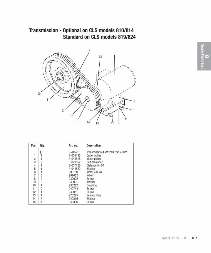
TransmissionV- Belts, Inspection, and AdjustmentThe granulator is driven by 3 V-belts.
Checking the V-belts
The tension and condition of the V-belts must be checked after 20 - 30 hours of operation at full load.After this, check the V-belts for damage once a month.Check the belt tension every 6 months.• Undo and remove the upper panel on the right-hand side of the granulator.• Rotate the V-belts a few turns.Check that the belts are intact, undamaged and uncracked.• Check belt tension and adjust if necessary.Motors up to 7.5 kW:• Load each one of the belts in turn with
4.45 lbf. (20 N), centrally between the cutter and belt pulleys. It should not be possible to depress the belt more than about 0.197 in. (5 mm).
11 kW motor:• Load each one of the belts in turn with 6.07 lbf. (27 N), centrally between
the cutter and belt pulleys. It should not be possible to depress the belt more than about 0.197 in. (5 mm).
Motors up to 7,5 kWL = 0.197in. (5 mm); F = 4.45lbf. (20 N)11 kW motorL = 0.197in. (5 mm); F = 6.07 lbf (27 N)
WARNING: Pinch riskbetween pulleys andV-belts.
7-6 l Service
AB
B
V-belt Adjustment
• Remove the upper panel on the right-hand side of the granulator.• CLS series-noise encapsulated machine, remove the rear guard plate
above the motor and open the door.• Undo and remove the extraction pipe. Alt. CLS series-machine with
extraction fan, undo the quick coupling on the outlet pipe stub.• Remove the granule bin.• Undo the motor screws (A) lightly, 4 pcs.• Adjust the belt tension by increasing/reducing the distance of the motor to
the cutter pulley, using the motor adjustment screws (B), 2 pcs.• Tighten the motor screws (33.2lb-ft [45 Nm] torque)• If the belt tension is adjusted, the belt need to be re-checked after 20 - 30
hours at full load.
Transmission (continued)
7Service
S e r v i ce l 7-7
Lubrication
Cutter Housing
The bearings in the cutter housing are permanently greased, and do not need greas-ing in normal circumstances.
7-8 l Service
Cutter Pulley/Motor PulleyThe upper panel on the right-hand side of the granulator must be removed toremove/install the cutter or motor pulleys.This makes the cutter and motor pulleys accessible.
Removal
Cutter Pulley
The pulley is mounted with a compres-sion bush.• Undo all screws a few turns (8 pcs.)• Remove two screws.• Put a drop of oil into the extractor
hole (A), and insert the two screws.• Tighten the screws, using progressively
increased torque until the compression bush comes away from the shaft.
• Lift off the cutter pulley, complete with the compression bush, from the shaft.
Motor Pulley
• Undo the socket cap screw on the pulley.• Remove the pulley with a puller.
Installing
Motor Pulley
Lift the pulley onto the motor shaft, make sure that the key fits.• Tighten the pulley with the socket cap screws on the shaft,
88.5lb-ft (120 Nm).
Cutter Pulley
The pulley is fitted with a compression bush.• Clean and degrease the cutter pulley.• Oil the cutter shaft.• Oil the screws and fit the compression bush lightly on the pulley.• Lift the pulley on to the cutter shaft.• Make sure that the pulleys line up.• Tighten the screws in the compression bush.
Tighten the screws alternately with the same torque, progressively increasing the torque to 14.8lb-ft (20 Nm).
• Tap the compression bush between the shaft and the screws. Use a block of wood or plastic.
• Tighten the pulley with the compression bush. Tighten the screws with alternating increased torque to 29.5lb-ft (40 Nm).
A
7Service
S e r v i ce l 7-9
7-10 l Service
Spare Par ts L i s t
Cu t t i ng Chamber . . . . . . . . . . . . . . . . . . . . 8 -3
S ta gge red Ro to r . . . . . . . . . . . . . . . . . . . . 8 -4
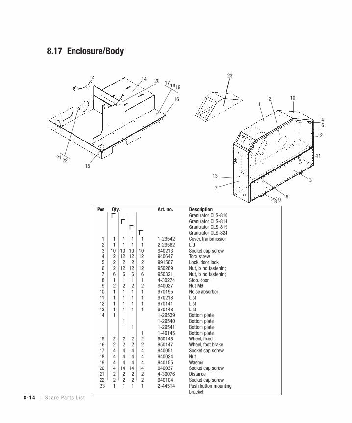
Spare Parts ListOrdering Spare PartsOnly use spare parts from Conair when replacing machine parts. Orders should go to the representative in the country where the machine was purchased. When ordering, the following should be specified:• Machine designation, as specified on the machine plate.• Serial number, as specified on the machine plate.• Part number, as specified in the spare parts list.• Quantity, as specified in this spare parts list.
Wiring diagramNever change or modify the basic electrical settings of the granulator, without first obtaining permission from Conair.
If the granulator settings are changed, the machine can be seriously damaged.All Warranties and Conair’s Product Liability will be void, if the basic set-tings of the granulator are changed.All maintenance and service work must be done by trained and competent per-sonnel!
Electrical installation must only be done by a competent electrician!The distribution box of the granulator is located on the right, low down.
Motor overload circuitbreaker (F1)
Motor overload circuitbreaker (F1)
Conveyor belt overload circuit breaker (F3)
CLS series-noise encapsulatedmachine
CLS series-noise encapsulated machine with conveyor Blower overload circuit
breaker (F2)
9-2 l W i r i ng D i a g ram
Current Sensing RelayThe granulator can be equipped with an optional current sensing relay tocontrol the feed equipment.
The current sensing relay detects the mill motor current consumption andcan temporarily stop accessories such as conveyors, roller feeders etc toavoid putting further material into the hopper, when the mill is runningunder heavy loading.
The relay stops and re-starts accessory equipment automatically, without re-setting.
Relay functions and normal settings:
T1 – Start delay, prevents the relay from breaking on connection (0.1 - 10 sec).The default start delay is 0.1 seconds.
T2 – Reaction time, prevents the relay from breaking during temporary high loading (0.1 - 3 sec).Default reaction time is 3.0 seconds.
A – Hysteresis, adjustable between 5 - 50% of the set limit.Default hysteresis is 20 %.
B – Limit value, adjustable between 0 - 100 %.Default setting depends on the current transformer size.Check the current transformer size and then check the default setting for this granulator.
C – Relay function, N = normal; I = inverted;
A T2 B
C T1 9W
iring Diagram
W i r i ng D i a g ram l 9-3
ConnectionThe current sensing relay is connected in series with the mill motor via a current transformer.The transformer is connected between M and E1/E2/E3 depending on the secondary current.(For transformers with transformation to 1 A, this is connected to E2.)
ExampleThe granulator is equipped with a current sensing relay to control a conveyor.A motor of 7.5 kW has a rated current of about 15 A.When this star/delta is started, it pulls about 15 A/ i.e. about 9 A per phase.
Relay Setting:
Motor size 15 A/ = 8,7 A per phase
T1 – Start delay setting 0.1 second.
T2 – Reaction time setting 3.0 seconds.
A – Hysteresis 20 %.
B – Limit value 30 %.
C – Relay function N normal.
• The current transformer size is 30/1A.
• The current transformer is connected to E2 (1 A).• In a current transformer with a transformation ratio of 30/1, the limit value
B should be set to 30 % or 9 A (30 A = 100 %).• The current sensing relay detects the current consumption of the granulator
motor and stops the conveyor, when the granulator motor exceeds 9 A for 3 seconds, to prevent further material from being fed into the hopper.
• The relay re-starts the conveyor automatically when the granulator motor
consumption has fallen 20 % below 9 A, i.e. to 7 A without a time delay.
A T2 B
C T1
9W
iring Diagram
W i r i ng D i a g ram l 9-5
9-6 l W i r i ng D i a g ram
Accessor ies
Orde r i ng Spa re Pa r t s . . . . . . . . . . . . . . . . 10-2
Th i rd F i xed Kn i f e , Remov ing , I ns t a l l i ng . . . 10-3
S E C T I O N
1 01
0Accessories
A c cesso r i es l 10-1
Accessor iesOrdering Spare PartsOnly use original Conair spare parts when replacing machinery components.Orders should be sent to the representative in the country where the machine was purchased.When ordering spare parts, please specify:• Machine type/designation, on the machine´s rating plate.• Serial number, on the machine´s rating plate.• Part number, from this list of spare parts.• Number of components.
10-2 l Accesso r i es
A
B C
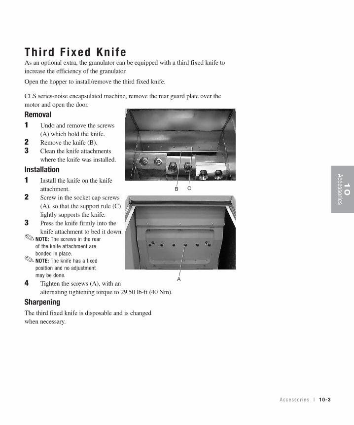
Th i rd F ixed Kn i feAs an optional extra, the granulator can be equipped with a third fixed knife toincrease the efficiency of the granulator.
Open the hopper to install/remove the third fixed knife.
CLS series-noise encapsulated machine, remove the rear guard plate over themotor and open the door.
Removal1 Undo and remove the screws
(A) which hold the knife.2 Remove the knife (B).3 Clean the knife attachments
where the knife was installed.
Installation1 Install the knife on the knife
attachment.2 Screw in the socket cap screws
(A), so that the support rule (C) lightly supports the knife.
3 Press the knife firmly into the knife attachment to bed it down.
NOTE: The screws in the rear of the knife attachment are bonded in place.NOTE: The knife has a fixed position and no adjustment may be done.
4 Tighten the screws (A), with an alternating tightening torque to 29.50 lb-ft (40 Nm).
SharpeningThe third fixed knife is disposable and is changed when necessary.
Unpack ing and Check ing . . . . . . . . . . . . . 11-2
L i f t i ng and Transpo r t t o P l ace o f Use . . . . . 11-2
Pos i t i on i ng i n P l ace o f Use . . . . . . . . . . . . 11-2
S to ra ge . . . . . . . . . . . . . . . . . . . . . . . . 11-3
Long-Te rm S to ra ge /Conse r va t i on . . . . . . . . 11-3
S E C T I O N
1 11
1Transport and Storeage
Tr anspo r t and S to ra ge l 11-1
Transpor t and s to rageGeneralThe machine should be transported by trained personnel.The machine is delivered packed in protective plastic foil, fixed to a pallet with straps.
Unpacking and Checking• Check that the machine has not been damaged during transport.
NOTE: Report any damage to the forwarding agent.
• Do not unpack the machine before it has been transported to where it is going to be used.
• Check with the delivery note that the delivery is complete.
Positioning in Place of UseSee Installation, Section 5.
✐
11-2 l Tr anspo r t and S to ra ge
StorageThe machine is packed for transport to the place where it is to be used. On delivery it is protected with Castrol DWX 22 anti-rust oil.
Long-Term Storage/Conservation• Store the machine in a room with a stable, dry temperature.• Treat the unpainted surfaces of the machine with rust preventer, such as
Castrol DWX 22. DWX 22 will protect the machine up to 12 months. . . . . . Alternatively, DWX 160 will provide protection for 24 - 36 months.
Transpo r t and S to ra ge l 11-3
11
Transport and Storeage
11-3 l Tr anspo r t and S to ra ge
We’re Here to He lpConair has made the largest investment in customer support in the plastics indus-try. Our service experts are available to help with any problem you might haveinstalling and operating your equipment. Your Conair sales representative also can help analyze the nature of your problem, assuring that it did not result frommisapplication or improper use.
How to Contac t Cus tomer Ser v iceTo contact Customer Service personnel, call:
From outside the United States, call: 814-437-6861
You can commission Conair service personnel to provide on-site service by con-tacting the Customer Service Department. Standard rates include an on-site hourlyrate, with a one-day minimum plus expenses.
Before You Ca l l . . .If you do have a problem, please complete the following checklist before calling Conair:
❒ Make sure you have all model, serial and parts list numbers for your particularequipment. Service personnel will need this information to assist you.
❒ Make sure power is supplied to the equipment.
❒ Make sure that all connectors and wires within and between control systemsand related components have been installed correctly.
❒ Check the troubleshooting guide of this manual for a solution.
❒ Thoroughly examine the instruction manual(s) for associated equipment, especial-ly controls. Each manual may have its own troubleshooting guide to help you.
❒ Check that the equipment has been operated as described in this manual.
❒ Check accompanying schematic drawings for information on special considerations.
Additional manuals and prints foryour Conair equipment may beordered through the CustomerService or Parts Department for anominal fee.
✐
A ppend i x l A-1
A-2 l A ppend i x
Equ ipment Guaran teeConair guarantees the machinery and equipment on this order, for a period asdefined in the quotation from date of shipment, against defects in material andworkmanship under the normal use and service for which it was recommended(except for parts that are typically replaced after normal usage, such as filters, liner plates, etc.). Conair’s guarantee is limited to replacing, at our option, the partor parts determined by us to be defective after examination. The customer assumesthe cost of transportation of the part or parts to and from the factory.
Per fo rmance War ran tyConair warrants that this equipment will perform at or above the ratings stated inspecific quotations covering the equipment or as detailed in engineering specifica-tions, provided the equipment is applied, installed, operated and maintained in therecommended manner as outlined in our quotation or specifications.
Should performance not meet warranted levels, Conair at its discretion will exercise one of the following options:
• Inspect the equipment and perform alterations or adjustments to satisfy performance claims. (Charges for such inspections and corrections will bewaived unless failure to meet warranty is due to misapplication, improper installation, poor maintenance practices or improper operation.)
• Replace the original equipment with other Conair equipment that will meet original performance claims at no extra cost to the customer.
• Refund the invoiced cost to the customer. Credit is subject to prior notice by thecustomer at which time a Return Goods Authorization Number (RGA) will beissued by Conair’s Service Department. Returned equipment must be well cratedand in proper operating condition, including all parts. Returns must be prepaid.
Purchaser must notify Conair in writing of any claim and provide a customerreceipt and other evidence that a claim is being made.
Warranty L imi ta t ionsExcept for the Equipment Guarantee and Performance Warranty statedabove, Conair disclaims all other warranties with respect to the equipment,express or implied, arising by operation of law, course of dealing, usage oftrade or otherwise, including but not limited to the implied warranties ofmerchantability and fitness for a particular purpose.