Visit us on the web: www.servo-repair.com www.servorepair.ca www.ferrocontrol.com www.sandvikrepair.com www.accuelectric.com For 24/7 repair services : USA: 1 (888) 932 - 9183 Canada: 1 (905) 829 -2505 Emergency After hours: 1 (416) 624 0386 Servicing USA and Canada Scroll down to view your document! Over 100 years cumulative experience 24 hour rush turnaround / technical support service Established in 1993 The leading independent repairer of servo motors and drives in North America.
Transcript
Visit us on the web:
www.servo-repair.com www.servorepair.ca
www.ferrocontrol.com www.sandvikrepair.com
www.accuelectric.com
For 24/7 repair services :
USA: 1 (888) 932 - 9183 Canada: 1 (905) 829 -2505
Emergency After hours: 1 (416) 624 0386
Servicing USA and Canada
Scroll down to view your document!
Over 100 years cumulative experience
24 hour rush turnaround / technical support service
Established in 1993
The leading independent repairer of servo motors and drives in North America.
User Manual
!"#$%
Because of the variety of uses for this equipment and because of thedifferences between this solid-state equipment and electromechanicalequipment, the user of and those responsible for applying this equipmentmust satisfy themselves as to the acceptability of each application and useof the equipment. In no event will Allen-Bradley Company be responsibleor liable for indirect or consequential damages resulting from the use orapplication of this equipment.
The illustrations shown in this manual are intended solely to illustrate thetext of this manual. Because of the many variables and requirementsassociated with any particular installation, the Allen-Bradley Companycannot assume responsibility or liability for actual use based upon theillustrative uses and applications.
No patent liability is assumed by Allen-Bradley Company with respect touse of information, circuits or equipment described in this text.
Reproduction of the content of this manual, in whole or in part, withoutwritten permission of the Allen-Bradley Company is prohibited.
The information in this manual is organized in numbered chapters. Readeach chapter in sequence and perform procedures when you are instructedto do so. Do not proceed to the next chapter until you have completed allprocedures.
Throughout this manual we use notes to make you aware of safetyconsiderations:
!ATTENTION: Identifies information about practices orcircumstances that can lead to personal injury or death, propertydamage or economic loss.
Attentions help you:
• Identify a hazard.
• Avoid the hazard.
• Recognize the consequences.
Important: Identifies information that is especially important forsuccessful application and understanding of the product.
Shock Hazard labels may be located on or inside the drive to alertpeople that dangerous voltage may be present.
Summary of Changes
This release of the 1333-5.2 User Manual contains some new and correctedinformation. The new and corrected information is summarized in the tablebelow. For further information, refer to the page numbers provided.
!"## " $ %&
'()*"+,+-
)(##./ )(##./ !" %&
/ $##
$$0$$$$0001 000 2
$$$'$$0001 000 2
-. 345$000&-6"44!00011540
5000&-6"44!00011540
0 !" %&
*1& "1
5/ 27$18&1000
5/ 2718&1000
5/ 2718&1000
*1& "1
5/ 27$/ $7$18&1000 '
5/ 27/ $7$18&1000 '
5/ 27/ $7$18&1000 '
*1& "1
5/ 27$/ $718&1000 9
5/ 27/ $718&1000 9
5/ 27/ $718&1000 9
/ !"*:!*" )
Preface
P-1
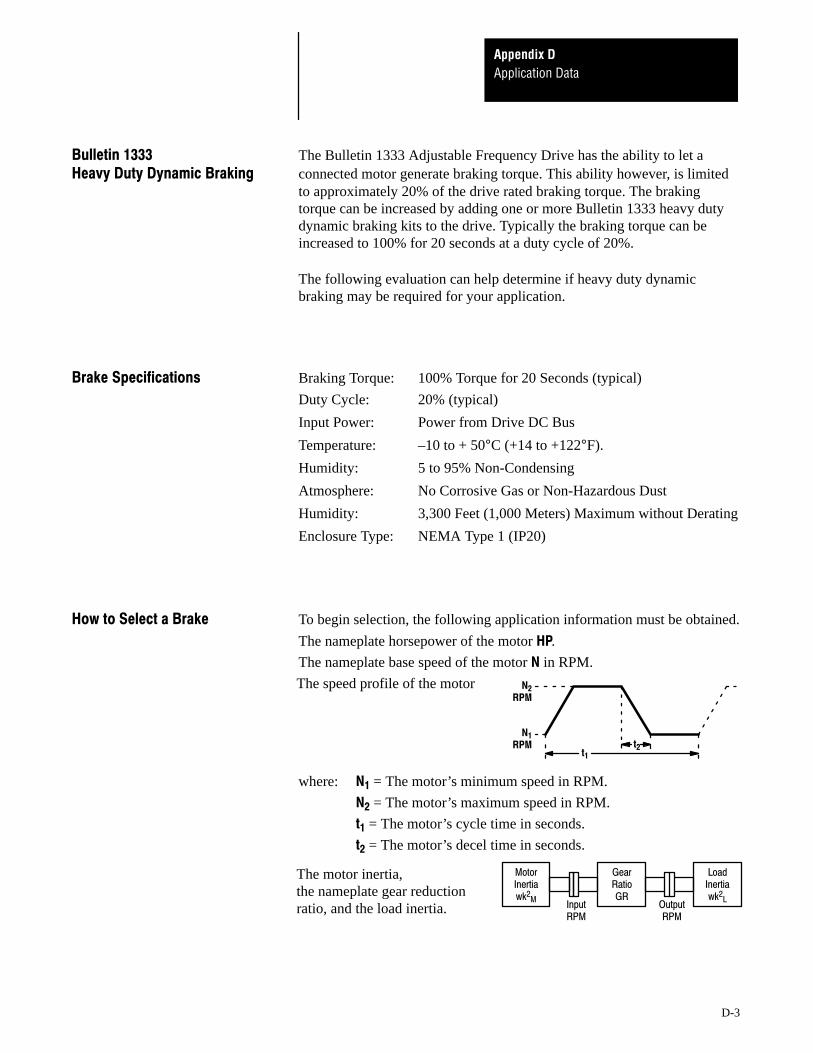
This manual defines the installation, operation, startup and fault codes forthe Allen-Bradley 1333 Series D Adjustable Frequency AC Drive. It isintended for use by personnel familiar with the functions of solid-statedrive equipment. Also provided are interconnection drawings for 1333options in Appendix A, and Bulletin 1333 Series D application data inAppendix D.
The 1333 Series D User Manual is designed to be read and used like anordinary textbook. Read the manual once from the beginning in the orderpresented to gain basic knowledge about your drive. Each chapter buildsupon information presented in the previous chapter. The majority of theinformation presented is arranged and written by drive function. Individualparameters in Chapter 5 are grouped under functional sub-headings (suchas Accel and Decel Settings or Volts-per-Hertz Curve Settings), as is thestatup procedure in Chapter 6. Appendix C provides paired parametertables which are also grouped by function to graphically show parameterinteraction.
To assure successful installation and operation, the material presented ineach chapter must be thoroughly read and understood before proceeding tothe next chapter. Particular attention should be directed to the Attention andImportant statements contained within. Become familiar with tasks thatmust be performed in a sequence for safety and successful completion.
Preface
P-2
This manual has been prepared primarily to support this product in a singleapplication. It is a standard document that is intended to help the userunderstand the individual operating characteristics and limitations of thisequipment including hazards associated with installation and setupprocedures. Note the following points:
• This equipment has been designed to meet the requirements of acomponent in an integrated system.
• It must be noted that special considerations are to be given tocharacteristics of other peripheral solid-state control equipment and thecumulative impact on safety.
• Manufacturers and engineering groups responsible for specification ordesign of electrical control equipment must refer to applicable industrystandards and codes for specific safety guidelines and interfacerequirements.
• In the actual factory environment, the user is responsible to assurecompliance with applicable machine and operator safety codes orregulations which are beyond the scope and purpose of this document.
In addition to the precautions listed throughout this manual, the followingstatements which are general to the system must be read and understood.
!ATTENTION: Only personnel familiar with the 1333 AC Driveand associated machinery should plan or implement theinstallation, start-up and subsequent maintenance of the system.Failure to comply may result in personal injury and/or equipmentdamage.
!ATTENTION: An incorrectly applied or installed system canresult in component damage or reduction in product life. Wiring orapplication errors, such as undersizing the motor, incorrect orinadequate AC supply, or excessive ambient temperatures mayresult in malfunction of the system.
!ATTENTION: This assembly may contain parts andsub-assemblies that are sensitive to electrostatic discharge. Staticcontrol precautions are required when testing, servicing orrepairing this assembly. Component damage may result if youignore electrostatic discharge control procedures. If you are notfamiliar with static control procedures, reference Allen-BradleyPublication 8000-4.5.2, Guarding Against Electrostatic Damage orany other applicable ESD protection handbook.
1Chapter
1-1
Pre-Installation Care
Before installing and operating your 1333 Series D drive, carefully readthis manual and observe all precautions. The catalog number of your driveas explained in Chapter 2 — Drive Identification lists the drive rating, typeof enclosure, nominal line voltage, phase and frequency. Specifications forall drives including standard controls, adjustment range, diagnostics andenvironmental qualifications are listed in Chapter 3 — Specifications.
Receiving Once you have received your drive, careful inspection for shipping damagemust be made. Damage to the shipping carton is usually a good indicationthat it has received improper handling. Any and all damage should beimmediately reported to the freight carrier and your nearest Allen-BradleyArea Sales/Support Center.
Carefully unpack the drive, taking care to save the shipping carton and anypacking material should return be necessary. Verify that the items on thepacking list or bill of lading agree with your order.
Storage If the drive will not immediately be installed, it should be stored in a clean,dry area where the ambient temperature is not less than -25°C nor morethan +65°C. The drive must not be stored in a corrosive environment norsubject to conditions in excess of the storage environment parametersstated in Chapter 3 — Specifications.
Shipping The carton and materials that came with your drive have been designed andtested to provide reasonable protection against damage during transit.Should the drive be shipped to another location, it is recommended that theoriginal shipping carton and packing material be used to protect the drivefrom damage in transit.
Pre-Installation CareChapter 1
1-2
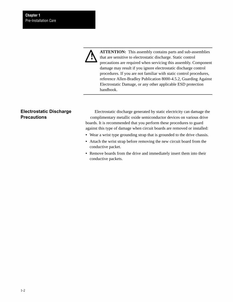
!ATTENTION: This assembly contains parts and sub-assembliesthat are sensitive to electrostatic discharge. Static controlprecautions are required when servicing this assembly. Componentdamage may result if you ignore electrostatic discharge controlprocedures. If you are not familiar with static control procedures,reference Allen-Bradley Publication 8000-4.5.2, Guarding AgainstElectrostatic Damage, or any other applicable ESD protectionhandbook.
Electrostatic Discharge Electrostatic discharge generated by static electricity can damage thePrecautions complimentary metallic oxide semiconductor devices on various drive
boards. It is recommended that you perform these procedures to guardagainst this type of damage when circuit boards are removed or installed:
• Wear a wrist type grounding strap that is grounded to the drive chassis.
• Attach the wrist strap before removing the new circuit board from theconductive packet.
• Remove boards from the drive and immediately insert them into theirconductive packets.
2Chapter
2-1
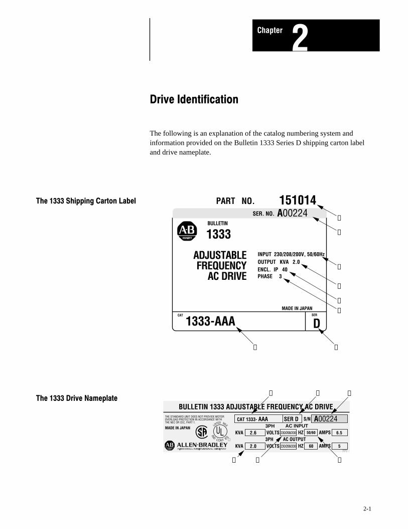
The following is an explanation of the catalog numbering system andinformation provided on the Bulletin 1333 Series D shipping carton labeland drive nameplate.
ADJUSTABLEFREQUENCY
AC DRIVE
INPUT 230/208/200V, 50/60Hz
BULLETIN
1333
PART NO. 151014SER. NO. A00224
MADE IN JAPAN
OUTPUT KVA 2.0ENCL. IP 40
1333-AAACAT SER
D
PHASE 3
➊ ➋
➐
➎
➍
➌
➏
➑
ULQETNOC
DNI
6L65DETSIL
BULLETIN 1333 ADJUSTABLE FREQUENCY AC DRIVETHE STANDARD UNIT DOES NOT PROVIDE MOTOROVERLOAD PROTECTION IN ACCORDANCE WITHTHE NEC OR CEC, PART 1.
MADE IN JAPAN
SER DCAT 1333- AAA S/N A00224
KVA VOLTS HZ AMPS3PH AC INPUT
2.6 230/208/200 6.550/60
KVA VOLTS HZ AMPS3PH AC OUTPUT
2.0 230/208/200 560
➊ ➋ ➐
➎ ➏ ➏
Drive IdentificationChapter 2
2-2
❶
The first letter indicates the drive rating.
200/208/230V AC, 3-Phase, 50/60 Hertz Input Voltage
Drives with the code ”B” are suitable for operating from any one of thesevoltage inputs: 380/415/460V AC, 50/60 Hz, 3-phase.
❷ Drive Series Number Series D.
❸ Drive Input/Output Power 3-Phase.
❹ Drive Enclosure Rating NEMA Type 1 (IP 20).
❺ Drive Output kVA Listed in Chapter 3, pg. 3-2.
❻ Drive Input Voltage Rating Explained above.
❼ Drive Serial Number Internal factory code.
❽ Drive Part Number Internal factory code.
3Chapter
3-1
Temperature: –10 to + 50°C (+14 to +122°F).
Relative Humidity: 5 to 95% non-condensing.
Altitude: 3,300 feet (1,000 meters) maximum withoutderating.
Vibration: Below 0.5G, 0.8 mm peak-to-peakamplitude, x-y-z direction.
Shock: 16G peak for 11ms duration.
Temperature: –25 to +65°C (–13 to +149°F)
Relative Humidity: 5 to 95% non-condensing.
NEMA Type 1 (IP20).
Indicated by catalog number.
Drive Rating ZAA-GAA AAB-CAB
Voltage: 200-230V AC, ± 10% 380-460V AC,± 10%
Frequency: 50/60 Hz, ± 5% 50/60 Hz, ± 5%
Phase: 1 or 3-phase 3-phase
Bus Overvoltage Trip: 430V DC 820V DC
Bus Undervoltage Trip: 160V DC 310V DC
Bus Overcurrent Trip: 200% IET
Power Ride-Thru: 15 ms or longer depending on the load.
Control Ride-Thru: 100 ms or longer depending on the load.
Control Logic Noise Showering arc transients from 350 to 2,000Immunity: volts.
SpecificationsChapter 3
3-2
!
"##$"#%$"&# !&'#$(#) *
"## +! "#% +! "&# +! "## +! "#% +! "&# +!)
, -
) . ! ! ! ! ! ! ! ! . /01$ 2
&%#$34'$3(# !&'#$(#) *
&%# +! 34' +! 3(# +! &%# +! 34' +! 3(# +!)
, -
) . ! ! ! ! ! ! ! ! . /01$ 2
❶ !
"##$"#%$"&# !4'#) *
"## +! "#% +! "&# +! "## +! "#% +! "&# +!)
, -
) . ! ! ! ! ! ! ! ! . /01$ 2
"##$"#%$"&# !4(#) *
"## +! "#% +! "&# +! "## +! "#% +! "&# +!)
,-
) . ! ! ! ! ! ! ! ! . /01$ 2
❶ !"#"$"#%&$'(")*"))&+"$,*"'(")*"+((&))"$&
*"*))'-$&(!"(&$*"#$."")("
SpecificationsChapter 3
3-3
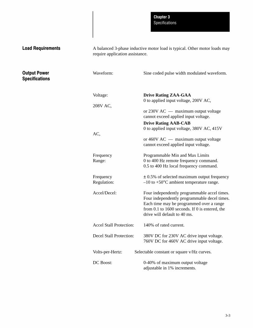
5,6 A balanced 3-phase inductive motor load is typical. Other motor loads mayrequire application assistance.
Waveform: Sine coded pulse width modulated waveform.
Voltage: Drive Rating ZAA-GAA0 to applied input voltage, 200V AC,
208V AC,or 230V AC –– maximum output voltagecannot exceed applied input voltage.
Drive Rating AAB-CAB0 to applied input voltage, 380V AC, 415V
AC,or 460V AC –– maximum output voltage cannot exceed applied input voltage.
Frequency Programmable Min and Max LimitsRange: 0 to 400 Hz remote frequency command.
0.5 to 400 Hz local frequency command.
Frequency ± 0.5% of selected maximum output frequencyRegulation: –10 to +50°C ambient temperature range.
Accel/Decel: Four independently programmable accel times.Four independently programmable decel times.Each time may be programmed over a range from 0.1 to 1600 seconds. If 0 is entered, thedrive will default to 40 ms.
Accel Stall Protection: 140% of rated current.
Decel Stall Protection: 380V DC for 230V AC drive input voltage.760V DC for 460V AC drive input voltage.
Volts-per-Hertz: Selectable constant or square v/Hz curves.
DC Boost: 0-40% of maximum output voltage adjustable in 1% increments.
SpecificationsChapter 3
3-4
Starting Torque: 150% nominal at 5 Hz.
Braking Torque: DC Brake: 20% of rated torque (standard) programmable duration and voltage
Heavy Duty Dynamic Brake: 100% of rated torque.
Stopping Frequency: 0.5-60 Hz
Intermittent Standard: 140% of rated output current forOverload Capability: 1 minute.
Inverse Trip: 125% of programmable overload trip level for one minute.
Drive Programmable overload trip function set to motorOverload Trip: nameplate value.
Ground Fault: Current sensors detect output ground fault at driveoutput leads.
7 68 Digital Input Local Speed ControlFrequency 0.01 Hz up to 100 Hz.Resolution: 0.1 Hz over 100 Hz.
Analog Input Remote Speed PotFrequency (Control Terminal Block, Terminals 1, 2 and 3)Resolution: 0.1 Hz up to 100 Hz.
0.2 Hz up to 200 Hz.0.5 Hz over 200 Hz.
0-5V DC Input(Control Terminal Block, Terminals 3 and 4)0.1 Hz up to 100 Hz.0.2 Hz up to 200 Hz.0.5 Hz over 200 Hz.
0-10V DC Input(Control Terminal Block, Terminals 3 and 4)0.1 Hz up to 100 Hz.0.2 Hz up to 200 Hz.0.5 Hz over 200 Hz.
4-20 mA Input(Control Terminal Block, Terminals 3 and 5)0.1 Hz up to 100 Hz.0.2 Hz up to 200 Hz.0.5 Hz over 200 Hz.
SpecificationsChapter 3
3-5
,6 As a minimum requirement for drive operation, the following four controlinputs must be present to operate the drive:
Start
A momentary contact closure will start the drive. The drive will continue torun until a stop input is issued or a drive fault occurs. A start input maycome from:
• Either of the Local Control Panel directional start pushbuttons.
• A user supplied N.O. contact or start switch connected to the Controland Signal Wiring Terminal Block.
Stop
A momentary open contact will stop the drive. A N.C. contact will permitthe drive to run or jog. A stop input may come from:
• The Local Control Panel stop pushbutton.
• A user supplied N.C. contact or stop switch connected to the Control andSignal Wiring Terminal Block.
Auxiliary Interlock
A maintained closed contact will permit the drive to start, run, or jog. Amomentary open contact will disable drive output. An auxiliary input maycome from:
• The factory installed metal jumper between terminals 16 and 17 of theControl and Signal Wiring Terminal Block.
• A user supplied N.C. contact or switch wired to terminals 16 and 17when the factory supplied jumper is removed.
Speed Reference
A speed reference sets the drive operating frequency. A speed referenceinput may come from:
• Either of the Local Control Panel directional start pushbuttons.
• A user supplied 10kΩ, 2W remote speed potentiometer connected to theControl and Signal Wiring Terminal Block.
• A 0-5V DC analog signal connected to the Control and Signal WiringTerminal Block.
• A 0-10V DC analog signal connected to the Control and Signal WiringTerminal Block.
• A 4-20 mA analog signal connected to the Control and Signal WiringTerminal Block.
• 1-3 programmable preset speed switches connected to the Control andSignal Wiring Terminal Block. Through programming, a total of sevenpreset speeds may be selected.
SpecificationsChapter 3
3-6
, The following optional inputs may be connected to the Series D Bulletin1333 drive at the Control and Signal Wiring Terminal Block.
Two or Three-Wire Start/Stop Control
Forward Reverse Control
Jog
Three Programmable Preset Speed Select Switches
Auxiliary Interlock
The following contact outputs are available as standard. Contacts areisolated from Logic Common and other drive circuitry and have thefollowing ratings.
Resistive rating: 120V AC or 30V DC, 1 Amp.
Inductive rating: 120V AC or 30V DC, 0.5 Amps.
At Speed: 1 N.O. contact, closed when the drive is at or abovecommand speed
Run or 1 N.O. contact closed when the drive is running, at Overload: programmed speed, at 140% of rated output current, or
over the programmable overload level.
No Fault/Fault: 1 set of Form C contacts that change state to indicate thatthe drive has received a fault or that a fault is present whenthe drive is powered up.
! 0-10V DC or 0-1 mA output programmable from 75-125% of runningfrequency.
8 Local Displays drive output frequency, equivalent motor Programming speed, drive output amps and drive control source. May beand Display toggled to program and display 62 drive parameters. Panel: Should a fault occur while the drive is running, the panel
will display the fault code.
Bus Charged: Internal neon display to indicate bus voltage is greater than50V DC.
4Chapter
4-1
The Series D 1333 is suitable for direct connection to a correct voltage ACpower line. There are however certain power line conditions which mayintroduce the possibility of drive input power component malfunction. Toreduce the possibility of these malfunctions, a line reactor or isolation typetransformer may be required. If the use of an input transformer is desired,only an isolation type transformer should be used.
The basic rules for determining if a line reactor or isolation typetransformer is required are as follows:
1. If the AC line supplying the drive has power factor correction capacitorsconnected, an AC line reactor or isolation type transformer must beconnected between the capacitor bank and the input to the drive.
2. If the AC line frequently experiences transient power interruptions orsignificant voltage spikes, an AC line reactor or isolation typetransformer should be used.
!ATTENTION: An incorrectly applied or installed system canresult in component damage or reduction in product life. The mostcommon causes are:
• Wiring the AC line to the drive output or control terminals.• Improper bypass or output circuits.• Output circuits which do not connect directly to the motor.• Incorrect or inadequate AC supply.• Excessive ambient temperature.
Contact Allen–Bradley for assistance with application or wiring.
Before actual installation, remove all packing material, wedges or bracesfrom within and around the drive. The 1333 must be installed in an areawhere the following installation and environmental guidelines are met.
• Cabinet mounting must be upright, leaving room for a minimumclearance of 4 inches (102 mm) on the top and bottom and 2 inches (51mm) on the sides for proper ventilation.
• The drive should be easily accessible for maintenance andtroubleshooting.
• The rated altitude must not exceed 3,300 feet (1,000 meters).• Vibration must be within the ratings outlined in Chapter 3 –
Specifications.• The ambient atmosphere must not contain volatile or corrosive gas,
vapors or dust.• The relative humidity must not exceed 95% for all drive ratings.• The ambient temperature for the drive must be kept within –10 to +50°C
for all ratings.
Installation and WiringChapter 4
4-2
!"#$%
& !%!'()'* )
+ , - " . + / * !
(NEMA Type 1 –– Front)
F FDA
G
G
EB
C
(NEMA Type 1 –– Side)
0.25 IN (6.35 MM) DIA. MOUNTING HOLES
I I H
K
(NEMA Type 1 –– Bottom)
J
0.905 IN (23.0 MM) DIA.CONDUIT ENTRY HOLES
ADJUSTABLE FREQUENCY AC MOTOR DRIVE
LOCK
Hz
A
SELECT
SHIFT
ENTER
STOP
NO.
F F
03
Installation and WiringChapter 4
4-3
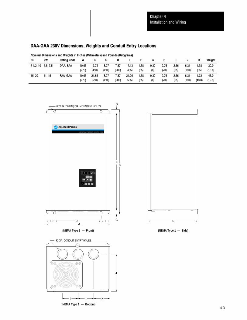
!"#$%
& !%!'()'* )
+ , - " . + / * !
K DIA. CONDUIT ENTRY HOLES
C
(NEMA Type 1 –– Side)(NEMA Type 1 –– Front)
FDA
G
0.28 IN (7.0 MM) DIA. MOUNTING HOLES
ADJUSTABLE FREQUENCY AC MOTOR DRIVE
LOCK
Hz
A
SELECT
SHIFT
ENTER
STOP
NO.
I 8 0 0
AI.
G
EB
F
J
I I H
(NEMA Type 1 –– Bottom)
Installation and WiringChapter 4
4-4
--01 !"#$%
& !%!'()'* )
+ , - " . + / * !
G
EB
(NEMA Type 1 –– Front)
F FDA
GC
(NEMA Type 1 –– Side)
0.25 IN (6.35 MM) DIA. MOUNTING HOLES
K
I I H
(NEMA Type 1 –– Bottom)
J
0.905 IN (23.0 MM) DIA.CONDUIT ENTRY HOLES
ADJUSTABLE FREQUENCY AC MOTOR DRIVE
LOCK
Hz
A
SELECT
SHIFT
ENTER
STOP
NO.
60.00
LL.
Installation and WiringChapter 4
4-5
!ATTENTION: Do not proceed without reading the informationon this page. Failure to understand procedures and hazards mayresult in personal injury or equipment damage.
%
1. The National Electrical Code requires that a circuit breaker or fusible disconnectswitch be provided in the drive branch circuit. Providing drive input fusingalone is not sufficient to meet NEC guidelines. The 1333 does not provide thisrequirement. Selection of a branch circuit breaker or fusible disconnect shouldbe based on the drive input current rating. Refer to the 3-Phase and 1-PhasePower Terminal Block Wiring sections in this chapter for mandatory AC inputfusing recommendations for drive short circuit protection.
2. The National Electrical Code requires that motor overload protection beprovided in the motor branch circuit. Parameter 6 when used with Parameter 7provides motor overload protection. NEC however, recognizes this protection asbeing provided by eutectic alloy or bi-metal overload relays. If it necessary tomeet NEC motor branch protection approval, eutectic alloy, bi-metal overloadrelays or an equivalent should be installed. Refer to article 430 of the NEC andany additional codes for specific requirements and additional information.
3. The National Electrical Code and local regulations govern the installation andwiring of the 1333. All input and output power wiring, control wiring andconduit must be brought through the drive conduit entry holes provided on theenclosure. Connections to the drive must be made as shown in the followingsections and in accordance with the drive nameplate, National Electrical Coderequirements and any additional interconnection diagrams packed with thedrive.
4. The voltage on each phase of the incoming line to the drive must match thedrive input rating. Verify the drive rating by referring to the input voltage listedon the drive nameplate. If the incoming line voltage is out of this tolerance,equipment may be damaged or fail to operate.
5. If multiple drives are used, do not use common cabling for AC input or outputleads. If multiconductor cable is used, separate 3-conductor input and outputcable for each drive must be used.
6. All signal wiring must be run separate from power or control wiring. Verify thatshielded cable and/or conduit is used if indicated on any interconnectiondiagrams or in the following sections. If shielded cable is required, shields mustbe grounded at the drive end only at one of the drive ground lugs provided.
7. Nearby relays, solenoids or brake coils can produce electrical noise transientsand cause erratic drive behavior. Transient suppression networks must be addedacross the coils of these devices.
8. Since most startup difficulties result from incorrect wiring, every precautionshould be taken to assure that the wiring is as indicated on the diagrams andinformation packed with the drive.
Installation and WiringChapter 4
4-6
&2 The following chart identifies general wire categories that will beencountered when installing the 1333 and other AC drives. Each categoryhas an associated wire group number that is used in the following sectionsto identify the wire to be used. Application and signal examples along withthe recommended type of cable for each group is provided. A matrixproviding the recommended minimum spacing between different wiregroups run in the same tray or separate conduit is also provided.
!"#
"$%
%%&' "(
)"*+,
)"* ",
,",-"!'
,",-"!'
,)"*
(&"!.!(&/.$%%&/
! &-"*.%0
! &1!2.%0
.!(&34%&
5,6-(/
,6
7&#-"!')-89
)-89
)"*.$%%&/8(/ $4( /
:,.$%%&/
)"*.$%%&/;;--"!'-<&
)$&/;(8(%$
7'"44(00=&
:"(0$' "=&)>
-"'&"0/(0
%%&' "(7?$4( /
&0(&0(&0(
&0(&0(
)>-"'&"0/
(0%%&' "(
7?$4( /
)>-"'&"0/
(0%%&' "(
7?$4( /
)>-"'&"0/
(0%%&' "(
7?$4( /
*("(0$
*("(0$
*("(0$
*("(0$
*("(0$
8(;#
8(;#
8(;#
8(;#
*("(0$
*("(0$
*("(0$
";#@7'"44(004(4$4/%'(!= *(0AA( *
!"$%/( 2/4 #
""(0$ @AA( *!"$%/4$/ =$((/% '"(0$
8('2/(0B&&4 /
"$%
)"*
)"*
"( "&
"( "&
.!(&
.!(&
)"*
.!(&
"( "&
All signal wiring must be run in separate steel conduit.A wire tray is not suitable.
The minimum spacing between conduit containing differentwire groups is 3.00 inches (78.2 mm).
1. The 1333 does not provide input power short circuit fusing.Specifications for the recommended fuse size and type to provide driveinput power protection against short circuits are provided on thefollowing pages. Branch circuit breakers or disconnect switches cannotprovide this level of protection for drive components.
2. Each Bulletin 1333 must have its own dedicated input and output powerleads. If multiconductor cable is used, separate 3-conductor input andoutput cable for each drive must be used.
3. For multimotor operation, the combined total of motor full load currentmust not exceed the rated output current of the drive.
4. Verify that the motor windings are properly connected to receive the fulldrive output voltage rating.
!ATTENTION:
1. Any disconnecting means wired to drive output terminals U/T1,
V/T2 and W/T3 must be capable of stopping the drive ifopened during drive operation. If opened during drive operation,the drive will continue to produce output voltage into an openmotor circuit causing a potential shock hazard.
2. The start/stop control circuitry in the 1333 includes solid-statecomponents. If hazards due to accidental contact with movingmachinery or unintentional flow of liquid, gas or solids exist, anadditional hard wired stop circuit is required to remove AC linepower to the drive. When AC input power is removed, there willbe a loss of inherent regenerative braking effect and the motorwill coast to a stop. An auxiliary braking method may berequired.
The 1333 is intended to be controlled by control input signalsthat will start and stop the motor. A device that routinelydisconnects then reapplies line power to the drive for the purposeof starting and stopping the motor must not be used. After ahard wired stop has been initiated, allow at least five minutesbefore reapplying input power to the drive. The allowablenumber of hard wired start/stops are 1 cycle within a 5 minuteperiod. Wait 5 minutes before attempting the next hard wiredstop cycle to allow the drive precharge resistors to cool.
Refer to codes and standards applicable to your particular systemfor specific requirements and additional information.
Installation and WiringChapter 4
4-8
Input and output power connections are marked on the drive Power Terminal Block. The Power Terminal Block is an eight position terminal
block located at the bottom of the Main Control Board. For maintenanceand setup procedures, the drive may be operated without a motorconnected.
!
"#$!%
&%'
(%)
*)++
Installation and WiringChapter 4
4-9
Input and output power connections are marked on the drive Power Terminal Block. The Power Terminal Block is an eight position terminal
block located at the bottom of the drive. For maintenance and setupprocedures, the drive may be operated without a motor connected.
!"#
$!%&!%#'()
*!+,,
Installation and WiringChapter 4
4-10
❶ ❶ ❶
❷
!
"
!
#"
!$%&
❶ User supplied drive input fuses.
❷ Motor disconnecting means including branch circuit, short circuit, and ground-fault protection.
Input AC line Terminals are not phase sensitive.
For drives rated ZAA-EAA, nominal 3-phase input voltage is200/208/230V AC, 50/60 Hz.
For drives rated AAB-CAB, nominal 3-phase input voltage is380/415/460V AC, 50/60 Hz.
Branch disconnect and short circuit protection is not part of the standard1333 and must be supplied by the user. Drive input fuses are required toprovide component protection against malfunction of electronic circuits.
!
Connect the motor leads to these terminals.
" #
DC bus terminals are reserved for the 1333 dynamic brake option. Refer tothe 1333 dynamic brake option instructions for installation and connectiondetails.
$%&
Two ground terminals have been provided in the drive. Either one of theseterminals must be connected to earth ground or the ground of the buildingelectrical system. The motor frame must also be connected to earth ground.Refer to the motor manufacturer’s installation instructions for specificdetails.
Installation and WiringChapter 4
4-11
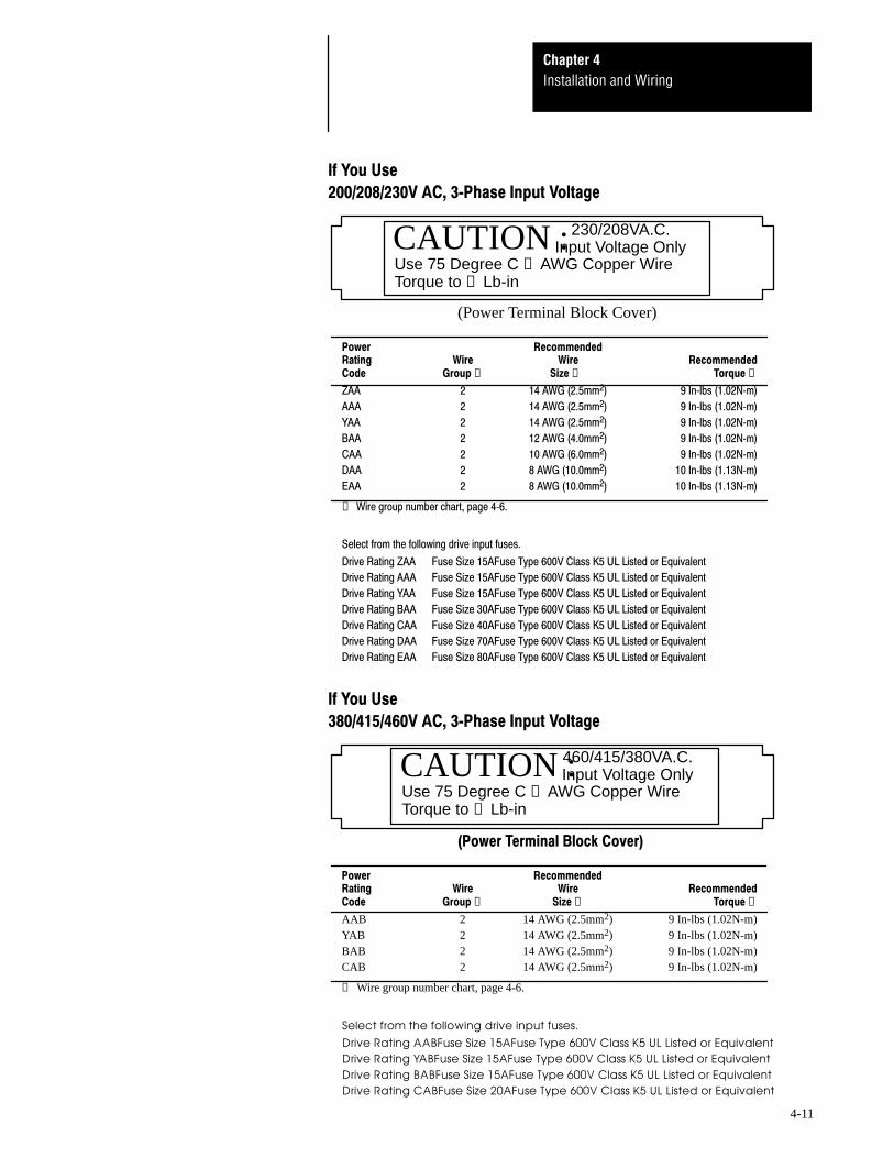
'()*
+++,+!-'.*/!/
00/ 00-0 $*.❶ 1❷ 2*❸
' " !()"*+", -./01)!*2"3.,
" !()"*+", -./01)!*2"3.,
4 " !()"*+", -./01)!*2"3.,
" !")(*2", -./01)!*2"3.,
" !2)5*2", -./01)!*2"3.,
$ " 6)!2*2", !2./01)!*!3.,
" 6)!2*2", !2./01)!*!3.,
❶ 7087(.5*
CAUTION :230/208VA.C.Input Voltage Only
Use 75 Degree C ❷ AWG Copper WireTorque to ❸ Lb-in
Use 75 Degree C ❷ AWG Copper WireTorque to ❸ Lb-in
6 -78
!""#$%&'' ()
* !""#$%&'' ()
!""#$%&'' ()
$ +" !""#$%&'' ()
Installation and WiringChapter 4
4-12
9$
!$%&
3$ 3$
❶
❶
❷
❶
!
"
!
#
"
❶ User supplied drive input fuses.
❶ Motor disconnecting means including branch circuit, short circuit, and ground-fault protection.
Input AC line Terminals are not phase sensitive.
For drives rated FAA or GAA, nominal 3-phase input voltage is200/208/230V AC, 50/60 Hz.
Branch disconnect and short circuit protection is not part of the standard1333 and must be supplied by the user. Drive input fuses are required toprovide component protection against malfunction of electronic circuits.
!
Connect the motor leads to these terminals.
" #
DC bus terminals are reserved for the 1333 dynamic brake option. Refer tothe 1333 dynamic brake option instructions for installation and connectiondetails.
$%&
Two ground terminals have been provided in the drive. Either one of theseterminals must be connected to earth ground or the ground of the buildingelectrical system. The motor frame must also be connected to earth ground.Refer to the motor manufacturer’s installation instructions for specificdetails.
Installation and WiringChapter 4
4-13
'()*
9$ /
Lugs are required to terminate wires for FAA or GAA units at the Power Terminal Block.
00/ -0 $*.❶ 1❷
< " 5)!5*2",
" )2*2",
❶ 7087(.5*
❸ 171?101//1777/*
71101=:1=1*
171/111/981792*(1)!2*!5A,1?*
6 -78
B3C "2"26#**7#/B/%
1@+$❷ 771**171❸
/99//:;7911*
$; < <1=!22<1%7522#/11>+1?;/
$; <1=!"+<1%7522#/11>+1?;/
Installation and WiringChapter 4
4-14
❶ ❶
!$%&
❷
!
"
!
#"
❶ User supplied drive input fuses.
❷ Motor disconnecting means including branch circuit, short circuit, and ground-fault protection.
0
Input AC line Terminals are not phase sensitive.
For drives rated ZAA-EAA, nominal 1-phase input voltage is200/208/230V AC, 50/60 Hz.
Branch disconnect and short circuit protection is not part of the standard1333 and must be supplied by the user. Drive input fuses are required toprovide component protection against malfunction of electronic circuits.
!
Connect the motor leads to these terminals.
" #
DC bus terminals are reserved for the 1333 Dynamic Brake Option. Referto the 1333 Dynamic Brake Option instructions for installation andconnection details.
$%&
Two ground terminals have been provided in the drive. Either one of theseterminals must be connected to earth ground or the ground of the buildingelectrical system. The motor frame must also be connected to earth ground.Refer to the motor installation instructions for specific details.
Use 75 Degree C ❷ AWG Copper WireTorque to ❸ Lb-in
(Power Terminal Block Cover)
/99//:;7911*
$; ' <1=!+<1%7522#/11>+1?;/
$; <1=!+<1%7522#/11>+1?;/
$; 4 <1=!+<1%7522#/11>+1?;/
$; <1=2<1%7522#/11>+1?;/
$; <1=(2<1%7522#/11>+1?;/
$; $ <1=@2<1%7522#/11>+1?;/
$; <1=62<1%7522#/11>+1?;/
Installation and WiringChapter 4
4-16
9$
!$%&
3$ 3$
❶ ❶
❷
!
"
!
#
"
❶ User supplied drive input fuses.
❷ Motor disconnecting means including branch circuit, short circuit, and ground-fault protection.
0
Input AC line Terminals are not phase sensitive.
For drives rated FAA or GAA, nominal 1-phase input voltage is200/208/230V AC, 50/60 Hz.
Branch disconnect and short circuit protection is not part of the standard1333 and must be supplied by the user. Drive input fuses are required toprovide component protection against malfunction of electronic circuits.
!
Connect the motor leads to these terminals.
" #
DC bus terminals are reserved for the 1333 Dynamic Brake Option. Referto the 1333 Dynamic Brake Option instructions for installation andconnection details.
$%&
Two ground terminals have been provided in the drive. Either one of theseterminals must be connected to earth ground or the ground of the buildingelectrical system. The motor frame must also be connected to earth ground.Refer to the motor installation instructions for specific details.
Installation and WiringChapter 4
4-17
'()*
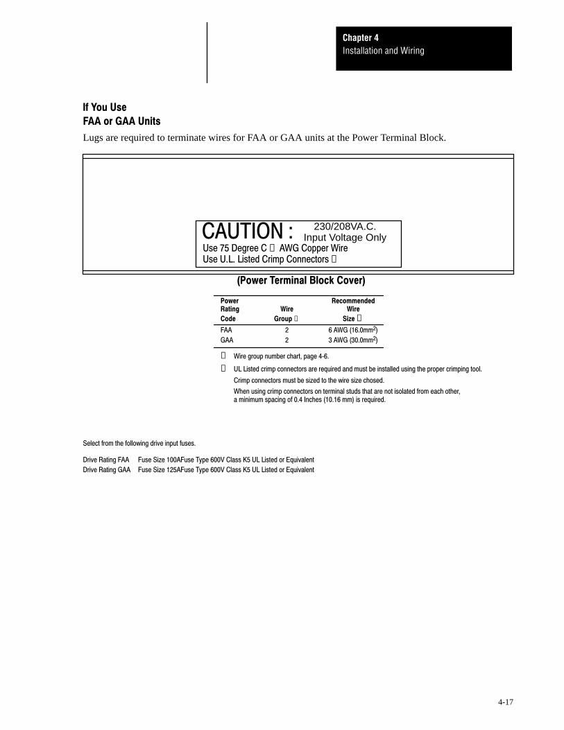
9$ /
Lugs are required to terminate wires for FAA or GAA units at the Power Terminal Block.
00/
-0 $*.❶ 1❷
< " 5)!5*2",
" )2*2",
❶ 7087(.5*
❸ 171?101//1777/*
71101=:1=1*
171/111/981792*(1)!2*!5A,1?*
6 -78
B3C 230/208VA.C.Input Voltage Only
1@+$❷ 771**171❸
/99//:;7911*
$; < <1=!22<1%7522#/11>+1?;/
$; <1=!"+<1%7522#/11>+1?;/
Installation and WiringChapter 4
4-18
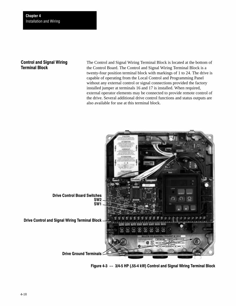
The Control and Signal Wiring Terminal Block is located at the bottom of the Control Board. The Control and Signal Wiring Terminal Block is a
twenty-four position terminal block with markings of 1 to 24. The drive iscapable of operating from the Local Control and Programming Panelwithout any external control or signal connections provided the factoryinstalled jumper at terminals 16 and 17 is installed. When required,external operator elements may be connected to provide remote control ofthe drive. Several additional drive control functions and status outputs arealso available for use at this terminal block.
!! "#$%&'(##$ )
Installation and WiringChapter 4
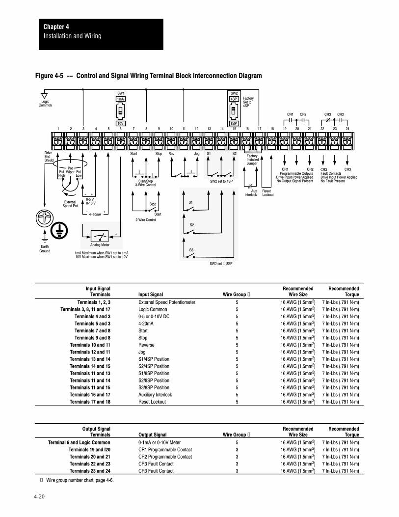
4-19
!"#$"%&'()(("*
Installation and WiringChapter 4
4-20
!
!
!
"# "# "#"#
$%
! &$
"# "#"#"#'(")*
+,
-."
."
#, /
#*)0(
$(1)0
&$)
"&&
&$%&(&*&$
*
*
.23 . 23
3
&&45((*
')61*/(&
3%&(&* 3
7(
+,1($85((*
+,1($8'(*
')6
❶ ! "
#$ .&$ . 3% $79:&&; 1.4*9:8.&;
%&'( "#&&4") $79:&&; 1.4*9:8.&;
'('% "#&&4") $79:&&; 1.4*9:8.&;
''') "#'(") $79:&&; 1.4*9:8.&;
')' "#'(") $79:&&; 1.4*9:8.&;
❶ ((&4)<.:
❶ ! "
%*'*) & $79:&&; 1.4*9:8.&;
)*+*%%%, )"&& $79:&&; 1.4*9:8.&;
) . . 3+" $79:&&; 1.4*9:8.&;
) . &$ $79:&&; 1.4*9:8.&;
,+ $79:&&; 1.4*9:8.&;
&+ $79:&&; 1.4*9:8.&;
%(%% #,* $79:&&; 1.4*9:8.&;
%'%% / $79:&&; 1.4*9:8.&;
%)% -* $79:&&; 1.4*9:8.&;
%% -* $79:&&; 1.4*9:8.&;
%%%) -* $79:&&; 1.4*9:8.&;
%%% -* $79:&&; 1.4*9:8.&;
%%% -* $79:&&; 1.4*9:8.&;
%#%, $(61)0 $79:&&; 1.4*9:8.&;
%,%+ #*)0( $79:&&; 1.4*9:8.&;
Installation and WiringChapter 4
4-21
Important: Control and signal functions affected by drive parameterselection and programming are indicated on the following pages. Refer tothe Programming section in Chapter 5 for detailed parameter operatingdescriptions.
%*')
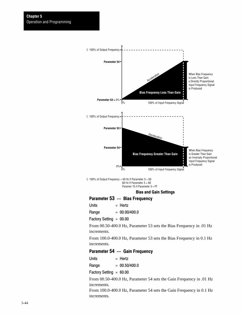
These terminals are provided for connecting a remote 10kΩ, 2Wpotentiometer. To enable a potentiometer to be connected to theseterminals, Parameter 9 must be set to 1, 2 or 3. The potentiometerfrequency control range is the range between minimum and maximumdrive frequency as set by Parameters 15, 16, 50, 51, 53 and/or 54. Thefrequency resolution is 0.1 Hz up to 100 Hz, 0.2 Hz up to 200 Hz, and0.5 Hz if over 200 Hz.
%
- ./
Full CW or high side external potentiometer connection.
'
-
Wiper external potentiometer connection.
)
- $ 0
Full CCW or low side external potentiometer connection.
)*+*%%*%,
$
These terminals are provided to terminate both minus and drive commonsignals to the Control and Signal Wiring Terminal Block.
)
( (%(12
This terminal is provided to terminate a 0 to +5 or +10V DC speedreference signal. The minus signal is terminated at Logic Common.Parameter 9 enables the speed reference signal and selects either a 0-5Vinput signal (when set to 1), or a 0-10V input signal (when set to 2).Parameters 52, 53 and 54 sets the output signal to be either directly orinversely proportional. The input impedance from Terminal 4 to logiccommon is approximately 40kΩ. The range of frequency control isbetween the minimum and maximum drive frequency settings or frequencyclamps as set by Parameters 15, 16, 50, 51, 53 and/or 54. The frequencyresolution is 0.1 Hz up to 100 Hz, 0.2 Hz up to 200 Hz, and 0.5 Hz if over200 Hz.
Installation and WiringChapter 4
4-22
!ATTENTION: Unexpected machine acceleration can cause injuryor death.
If Parameter 9 is set to a value other than 0, a loss of thepotentiometer low reference signal at terminal 3 of the driveterminal block will allow the drive to immediately accelerate tomaximum frequency if the drive is running or a start command hasbeen received.
Ensure that remote potentiometer connection integrity ismaintained and inspected in accordance with NFPA 70B standardsfor maintenance of electrical equipment.
!ATTENTION: Terminals 4, 5 and 6 are internally protected fromreverse polarity signals or input signals rising above 120% of themaximum input signal. If reverse polarity or levels are maintainedabove 120%, signals may be degraded and component damage mayresult.
)
'(23
This terminal is provided to terminate a +4 to 20 mA DC speed referencesignal. The minus signal is terminated at Logic Common. Parameter 9enables and selects the 4-20mA input signal. Parameters 52, 53 and 54 setsthe input signal to be either directly or inversely proportional. The inputimpedance from Terminal 5 to logic common is approximately 390Ω. Therange of frequency control is between the minimum and maximum drivefrequency settings or frequency clamps. The frequency resolution is 0.1 Hzup to 100 Hz, 0.2 Hz up to 200 Hz, and 0.5 Hz if over 200 Hz.
#)
3 4
This terminal provides a 0-1mA or 0-10V DC signal that may be used witha user supplied analog meter. The minus signal is terminated at logiccommon. Switch SW1, a 1mA/10V switch on the Control Board, sets theoutput signal to either 0-1mA or 0-10V.
For a 0–1mA voltage output, the load impedance of the meter must be10kΩ or less.
For a 0–10V voltage output, the load impedance of the meter must be300Ω or less.
Parameter 55 is used to set the 1mA output signal to equal 75-125% ofmaximum output frequency while the drive is running. Parameter 56 isused to adjust the 10V to equal 75-125% of maximum output frequencywhile the drive is running.
Installation and WiringChapter 4
4-23
,+
This remote input will command the drive to start if all hardwiredinterlocks are closed and Parameter 8 is set to 1 or 3. The drive willcontinue to run until a stop command is received, an interlock is opened,or a fault is detected.
Important: As shown in Figure 4-4, for external two wire start/stopcontrol, terminals 7 and 8 must be jumpered.
&+
This remote input will command the drive to stop if Parameter 8 is set to 1or 3. The drive will then either ramp-to-stop or coast-to-stop as selected byParameter 11.
Important: If ramp-to-stop is selected, refer to Parameters 11 and 18 ifthe drive will be subjected to an overhauling load. If Parameter 18 DecelFrequency Hold is set to 1 (On), an overhauling load may cause the decelramp to hold at one frequency for an extended period, causing ramp-to-stopcommands to appear to be non-functional.
%(+
5
This remote input will command the drive to reverse direction if Parameter8 is set to 1 or 3 and Parameter 10 is set to 0. Both the local and remotereverse will be locked out if Parameter 10 is set to 1.
%'%%
6
This remote input will jog the drive if Parameter 8 is set to 1 or 3. Whenjogged:
–– The drive will jog to the frequency range set by Parameter 26
–– Within the accel time set by Parameter 27
–– In the direction determined by Parameter 10.
When the jog pushbutton is released, the drive will decelerate within thetime set by Parameter 28.
Installation and WiringChapter 4
4-24
%)%%7-
%%'7-
Switch SW2 on the Control Board is factory set to 4SP. When set to 4SP,two external switches may be connected to the drive as shown in Figure4-3. In addition to the standard accel and decel rates set by Parameters 1and 2, these switches may then be used to select;
–– Three additional accel rates
–– Four preset speeds
As programmed by Parameters 19, 29-31 and 36-41.
%)%%%7+-
%%%'7+-
%%%)7+-
When switch SW2 on the Control Board is set to 8SP, a total of threeexternal switches may be connected to the drive as shown in Figure 4-3. Inaddition to the standard accel and decel rates set by Parameters 1 and 2,these switches may then be used to select three additional accel rates, threeadditional decel rates, and seven preset speeds, as programmed byParameters 19-20 and 29-41.
Important: If parameter 20 is set to 1, switch S1 and S2 will select thefour preset speeds defined by Parameters 29-31. Switch S3 is reserved forremotely setting a drive fault.
%#%,
389
These factory jumpered terminals are used to install an auxiliary externalinterlock when the jumper is removed. The interlock contact must beclosed to allow the drive to operate. The contact must be open for aminimum of 100mS to sense an auxiliary fault. Parameter 21 will allow anopen contact to generate either:
A no-fault coast-to-stop sequence displaying AS –– Auxiliary Stop.
A drive fault coast-to-stop sequence displaying AU –– Auxiliary Interlock–– which will cause the CR3 fault contacts to change state.
Important: A 5V DC or 5mA signal requires a gold contact relay.
Installation and WiringChapter 4
4-25
%+%,
$
These terminals may be jumpered or not jumpered to determine how the1333 is reset after a fault.
When the terminals are jumpered, a drive may only be reset and restartedby removing then re-applying input power to the drive.
When these terminals are left open, the drive will be reset and restarted asprogrammed by Parameters 47 and 48.
%&'(
- : %
These terminals allow drive supplied relay contact CR1 to be used inexternal circuits. When power is applied to the drive, the N.O. contact willremain N.O. until a programmed signal is received. The contact isprogrammed by Parameters 22 and 24 to signal that the drive is at theprogrammed set speed or 140% of rated drive current. The contact isisolated from Logic Common and other drive circuitry.
"#
"#5(
"#
"#5(
- 3
%(; <5= -
Resistive rating: 120V AC or 30V DC, 1 Amp.
Inductive rating: 120V AC or 30V DC, 0.5 Amps.
Installation and WiringChapter 4
4-26
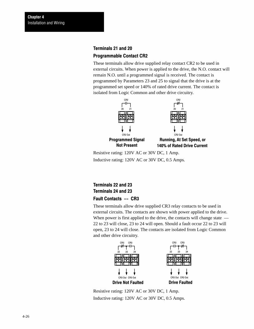
'%'(
- : '
These terminals allow drive supplied relay contact CR2 to be used inexternal circuits. When power is applied to the drive, the N.O. contact willremain N.O. until a programmed signal is received. The contact isprogrammed by Parameters 23 and 25 to signal that the drive is at theprogrammed set speed or 140% of rated drive current. The contact isisolated from Logic Common and other drive circuitry.
"#
"#5(
"#
"#5(
*3*
%(; <5
-
= -
Resistive rating: 120V AC or 30V DC, 1 Amp.
Inductive rating: 120V AC or 30V DC, 0.5 Amps.
''')
'')
)
These terminals allow drive supplied CR3 relay contacts to be used inexternal circuits. The contacts are shown with power applied to the drive.When power is first applied to the drive, the contacts will change state ––22 to 23 will close, 23 to 24 will open. Should a fault occur 22 to 23 willopen, 23 to 24 will close. The contacts are isolated from Logic Commonand other drive circuitry.
5= 5
"#"#
"#5("#5(
"#"#
"#5("#5(
Resistive rating: 120V AC or 30V DC, 1 Amp.
Inductive rating: 120V AC or 30V DC, 0.5 Amps.
5Chapter
5-1
The Local Control and Programming Panel provides a convenient means to locally control the operating functions of the Series D Bulletin 1333 drive
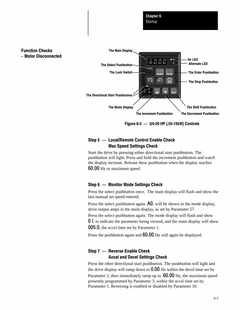
including start/stop, forward/reverse, and speed. The Local Control andProgramming Panel also contains two digital displays. A Main Display toshow drive running values, codes, and parameter values, and a ModeDisplay to show the drive mode and control source. Finally, the LocalControl and Programming Panel includes the controls necessary toprogram the various parameters that will define your drive.
With two exceptions, the drive must always be stopped to allow driveprogramming.
• A 0-1 mA Analog Output Meter may be calibrated while the drive isrunning by accessing Parameter 55.
• A 0-10V DC Analog Output Meter may be calibrated while the drive isrunning by accessing Parameters 56.
Operation and ProgrammingChapter 5
5-2
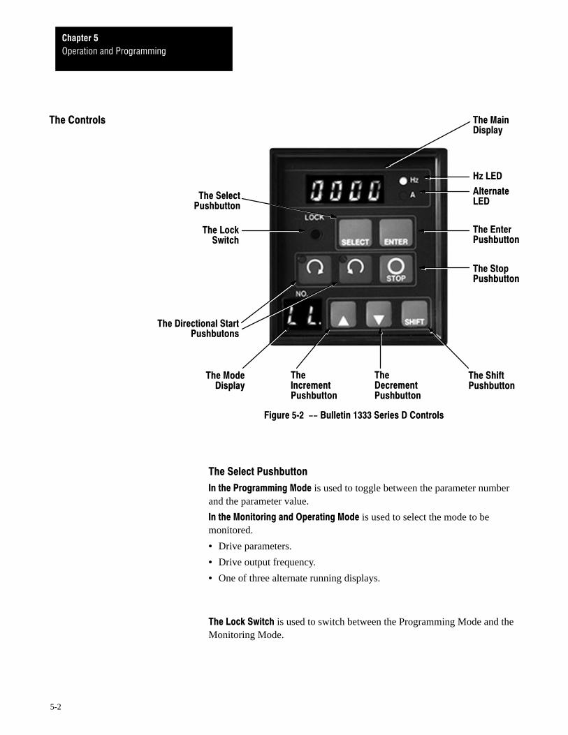
!
"#$
%$
$&
&
'&
&
(&
!
)*
&
&
+
&
( is used to toggle between the parameter numberand the parameter value.
( is used to select the mode to bemonitored.
• Drive parameters.
• Drive output frequency.
• One of three alternate running displays.
)* is used to switch between the Programming Mode and theMonitoring Mode.
Operation and ProgrammingChapter 5
5-3
are not functional.
In the Monitoring and Operating Mode are used to start or jog the drivewhenever drive speed is controlled from the Local Control Panel.
are used to select parameters or increase anddecrease parameter values.
are used to increment or decrementdrive speed whenever drive speed is controlled from the Local ControlPanel.
is used to shift between display segments in boththe Main and Mode Displays.
is used to shift between segments inthe Main display, or between jog and run in the Mode display when thedrive is stopped.
is not functional.
will always stop the drive asdescribed in The Displays section that follows.
is used to enter the parameter value.
is used to enter changes.
• Enter changes in drive speed whenever drive speed is controlled fromthe Local Control Panel.
• Enter adjustment values to calibrate a 0-1 mA or 0-10V DC analogoutput meter.
Operation and ProgrammingChapter 5
5-4
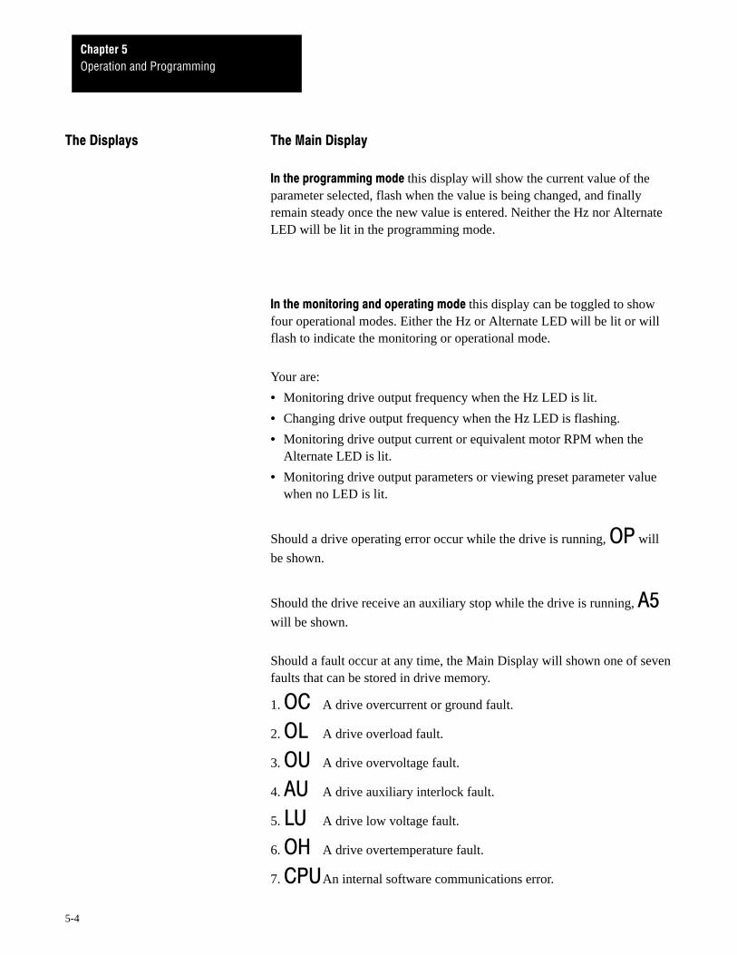
this display will show the current value of theparameter selected, flash when the value is being changed, and finallyremain steady once the new value is entered. Neither the Hz nor AlternateLED will be lit in the programming mode.
this display can be toggled to showfour operational modes. Either the Hz or Alternate LED will be lit or willflash to indicate the monitoring or operational mode.
Your are:
• Monitoring drive output frequency when the Hz LED is lit.
• Changing drive output frequency when the Hz LED is flashing.
• Monitoring drive output current or equivalent motor RPM when theAlternate LED is lit.
• Monitoring drive output parameters or viewing preset parameter valuewhen no LED is lit.
Should a drive operating error occur while the drive is running, will
be shown.
Should the drive receive an auxiliary stop while the drive is running, will be shown.
Should a fault occur at any time, the Main Display will shown one of sevenfaults that can be stored in drive memory.
1. A drive overcurrent or ground fault.
2. A drive overload fault.
3. A drive overvoltage fault.
4. A drive auxiliary interlock fault.
5. A drive low voltage fault.
6. A drive overtemperature fault.
7. An internal software communications error.
Operation and ProgrammingChapter 5
5-5
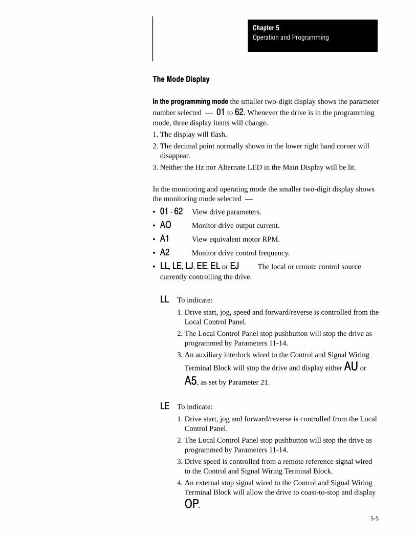
the smaller two-digit display shows the parameter
number selected –– to . Whenever the drive is in the programmingmode, three display items will change.
1. The display will flash.
2. The decimal point normally shown in the lower right hand corner willdisappear.
3. Neither the Hz nor Alternate LED in the Main Display will be lit.
In the monitoring and operating mode the smaller two-digit display showsthe monitoring mode selected ––
• View drive parameters.
• Monitor drive output current.
• View equivalent motor RPM.
• Monitor drive control frequency.
• or The local or remote control sourcecurrently controlling the drive.
To indicate:
1. Drive start, jog, speed and forward/reverse is controlled from theLocal Control Panel.
2. The Local Control Panel stop pushbutton will stop the drive asprogrammed by Parameters 11-14.
3. An auxiliary interlock wired to the Control and Signal Wiring
Terminal Block will stop the drive and display either or
, as set by Parameter 21.
To indicate:
1. Drive start, jog and forward/reverse is controlled from the LocalControl Panel.
2. The Local Control Panel stop pushbutton will stop the drive asprogrammed by Parameters 11-14.
3. Drive speed is controlled from a remote reference signal wiredto the Control and Signal Wiring Terminal Block.
4. An external stop signal wired to the Control and Signal WiringTerminal Block will allow the drive to coast-to-stop and display
.
Operation and ProgrammingChapter 5
5-6
5. An auxiliary interlock wired to the Control and Signal Wiring
Terminal Block will stop the drive and display either or
, as set by Parameter 21.
To indicate the local jog function has been selected.
To indicate:
1. Drive start, jog, speed and forward/reverse is controlled byexternal devices or logic wired to the Control and Signal WiringTerminal Block.
2. An external stop signal wired to the Control and Signal WiringTerminal Block will stop the drive as programmed byParameters 11-14.
3. An auxiliary interlock wired to the Control and Signal Wiring
Terminal Block will stop the drive and display either or
, as set by Parameter 21.
4. The Local Control Panel stop pushbutton will allow the drive to
coast-to-stop and display .
To indicate:
1. Drive start, jog and forward/reverse is controlled by externaldevices or logic wired to the Control and Signal WiringTerminal Block.
2. Drive speed is controlled from the Local Control Panel.
3. An external stop signal wired to the Control and Signal WiringTerminal Block will stop the drive as programmed byParameters 11-14.
4. The Local Control Panel stop pushbutton will allow the drive to
coast-to-stop and display .
5. An auxiliary interlock wired to the Control and Signal Wiring
Terminal Block will stop the drive and display either or
, as set by Parameter 21.
To indicate an external jog signal is being sent.
Operation and ProgrammingChapter 5
5-7
62 parameters are available for adjusting the drive. All Series D 1333parameters interact with each other to provide optimum drive performance.Some specific parameters however, require that other parameters be set tocoordinated values if they are to function. Others require that they be set tospecific values to function with Bulletin 1333 options.
All parameters along with a detailed explanation are listed in the remainingpages of this chapter. Parameters are grouped under sub-headings byfunction, such as or !"#.An interactive matrix has been provided in Appendix C to graphicallyshow which parameters must be set to provide coordinated control of theBulletin 1333.
Operation and ProgrammingChapter 5
5-8
$%&& %
!
This parameter determines the time that it will take the drive to accelerateover a 60 Hz change in frequency. From 0 to 0.5 Hz, the accel rate iseffectively zero. From 0.5 Hz to maximum output frequency, the accel rateset by Parameter 1 will remain constant. The total time it will take the driveto accelerate from 0 to maximum drive output frequency is:Total time = (Maximum Drive Output Frequency × Parameter 1) ÷ 60.
If set to 0000, the drive will enter 40 ms but display 0000.
From 00.10-1000 seconds, this parameter sets the accel time value in 0.1second increments.
From 1000-1600 seconds, this parameter sets the accel time value in 1second increments.
Important: Parameter 11 must be set to 0 to allow the drive toramp-to-stop
This parameter determines the time that it will take the drive to decelerateand ramp-to-stop over a 60 Hz change in frequency. From 0.5 to 0 Hz, theaccel rate is non-linear and set by either DC injection braking or the DCdynamic brake if it is installed. From maximum output frequency to 0.5Hz, the accel rate set by Parameter 2 will remain constant. The total time itwill take the drive to decelerate from maximum drive output frequency to0.5 Hz is:Total time = (Maximum Drive Output Frequency × Parameter 2) ÷ 60.
If set to 0000, the drive will enter 40 ms but display 0000.
From 00.10-1000 seconds, this parameter sets the decel time value in 0.1second increments.
From 1000-1600 seconds, this parameter sets the decel time value in 1second increments.
00.5
60 Hz
Output Frequency
50 Hz
Parameter 3 = 50Hz
Time40mS
Parameter 2
noitar
elece
D
➊ DC injection braking or DC dynamic braking (if installed).
➊
00.5
60 Hz
Output Frequency
50 Hz
Parameter 3 = 60Hz
Time40mS
Parameter 2
noitar
elece
D
➊
Parameter 3 = FFParameter 15 = 120Hz
00.5
60 Hz
Output Frequency
50 Hz
Time40mS
Parameter 2
noitar
elece
D
➊
Operation and ProgrammingChapter 5
5-10
!"# Important: The maximum allowable drive output frequency will bedetermined by the lowest programmed value of any of the followingparameters:
• Parameter 3 Frequency Range
• Parameter 15 Maximum Frequency
• Parameter 51 Upper Frequency Clamp
• Parameter 53 Bias Frequency –– If Parameter 53 is Higher ThanParameter 54
• Parameter 54 Gain Frequency –– If Parameter 54 is Higher ThanParameter 53
$(&&)*+
"
This parameter permits the selection of three linear volts-per-Hertz ramps.The maximum frequency settings of these ramps are 50 Hz, 60 Hz, or FF.If the BCD Interface option is installed, Parameter 3 must be set to matchthe scaling jumper on the BCD Interface Board –– Either 60 for 60 Hzoperation, or FF for 120/200 Hz operation.
If set to 50, 50 Hz will be the maximum drive frequency –– The absolutemaximum output speed that the drive can reach. If set to 60, 60 Hz will bethe maximum drive frequency –– The absolute maximum output speedthat the drive can reach. Parameter 15 will have no effect on maximumoutput speed, but Parameter 51 will. When Parameter 3 is set to 50 or 60,the drive will use the lower of the values set by Parameter 3 and 51.Parameter 16 will have no effect on base speed.
If set to FF, the value set by Parameter 15 or 51 will be the maximum drivefrequency –– The absolute maximum output speed that the drive canreach. When Parameter 3 is set to FF, the drive will use the lower of thevalues set by Parameters 15 and 51. The value set by Parameter 16 BaseFrequency will be the point where maximum output voltage is applied tothe motor.
Important: Applications where volts-per-Hertz curves are required toreach maximum voltage other than at 50 or 60 Hz are primarily provisionsfor operating custom motors. For application assistance in these specialranges, contact your nearest Allen-Bradley representative.
Operation and ProgrammingChapter 5
5-11
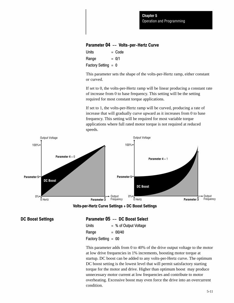
This parameter sets the shape of the volts-per-Hertz ramp, either constantor curved.
If set to 0, the volts-per-Hertz ramp will be linear producing a constant rateof increase from 0 to base frequency. This setting will be the settingrequired for most constant torque applications.
If set to 1, the volts-per-Hertz ramp will be curved, producing a rate ofincrease that will gradually curve upward as it increases from 0 to basefrequency. This setting will be required for most variable torqueapplications where full rated motor torque is not required at reducedspeeds.
100%
Parameter 3
DC Boost
0%0 Hertz
Parameter 5
Output Voltage
OutputFrequency
Parameter 4 = 0
100%
Parameter 3
DC Boost
0%0 Hertz
Parameter 5
Output Voltage
OutputFrequency
Parameter 4 = 1
This parameter adds from 0 to 40% of the drive output voltage to the motorat low drive frequencies in 1% increments, boosting motor torque atstartup. DC boost can be added to any volts-per-Hertz curve. The optimumDC boost setting is the lowest level that will permit satisfactory startingtorque for the motor and drive. Higher than optimum boost may produceunnecessary motor current at low frequencies and contribute to motoroverheating. Excessive boost may even force the drive into an overcurrentcondition.
Operation and ProgrammingChapter 5
5-12
Important: Parameters 6 and 7 are intended for use on single motorapplications. For multiple motor applications, Parameter 6 must be set to 0to help avoid nuisance tripping.
!"#
Parameter 6 provides three thermal overload functions. When used inconjunction with Parameter 7, a thermal overload function that matches themotor nameplate amps can be used.
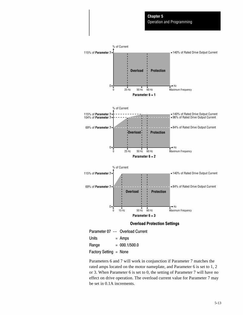
If set to 0, the overload function will not include thermal protection and thedrive will trip at its standard setting of 140% of rated drive output currentafter 60 seconds. If set to 1, 2 or 3, the thermal overload function isenabled and will function as described below.
If set to 1, the drive will trip at 115% of the current set in Parameter 7, or140% of rated drive output current (whichever is lower) after 60 seconds.When set to 1, the thermal overload trip point is constant across the entirespeed range of the motor. This performance is typical with A-B Bulletin1329 10:1 speed range motors.
If set to 2, the drive will trip at 115% of the current set in Parameter 7, or140% of rated drive output current (whichever is lower) after 60 seconds.When set to 2, the thermal overload curve generated is derated below50 Hz for use with motors having a 4:1 speed range. This performance istypical with A-B Bulletin 1329 4:1 speed range motors.
If set to 3, the drive will trip at 115% of the current set in Parameter 7, or140% of rated drive output current (whichever is lower) after 60 seconds.When set to 3, the thermal overload curve generated is derated below15 Hz for use with motors having a 4:1 speed range. This performance istypical with A-B Bulletin 1329 4:1 speed range motors.
Important: The National Electrical Code requires that motor overloadprotection be provided in the motor branch circuit. Parameter 6 when usedwith Parameter 7 provides motor overload protection. NEC however,recognizes this protection as being provided by eutectic alloy or bi-metaloverload relays. If it necessary to meet NEC motor branch protectionapproval, eutectic alloy, bi-metal overload relays or an equivalent shouldbe installed. Refer to article 430 of the NEC and any additional codes forspecific requirements and additional information.
Operation and ProgrammingChapter 5
5-13
0
115% of Parameter 7
% of Current
Parameter 6 = 10 25 Hz 50 Hz 60 Hz
140% of Rated Drive Output Current
HzMaximum Frequency
0
% of Current
Parameter 6 = 2
115% of Parameter 7
0 25 Hz 50 Hz 60 Hz
140% of Rated Drive Output Current
HzMaximum Frequency
69% of Parameter 7
104% of Parameter 7 96% of Rated Drive Output Current
84% of Rated Drive Output Current
0
% of Current
Parameter 6 = 3
115% of Parameter 7
0 15 Hz 50 Hz 60 Hz
140% of Rated Drive Output Current
HzMaximum Frequency
69% of Parameter 7 84% of Rated Drive Output Current
Overload Protection
Overload Protection
Overload Protection
!"#$$%
&"
'('
)
Parameters 6 and 7 will work in conjunction if Parameter 7 matches therated amps located on the motor nameplate, and Parameter 6 is set to 1, 2or 3. When Parameter 6 is set to 0, the setting of Parameter 7 will have noeffect on drive operation. The overload current value for Parameter 7 maybe set in 0.1A increments.
Operation and ProgrammingChapter 5
5-14
$ %& '( Important: If the Remote Operator Station option is installed, Parameter 8must be set to 1 or 3 to allow remote control.
!"*$$+"
This parameter enables or disables the drive start, jog, and forward/reversefunctions as follows. The stop button on the Local Control and
Programming Panel will always be functional, but may generate an OPerror for certain settings detailed below. If installed at the Control andSignal Wiring Terminal Block, auxiliary input switches S1, S2 and/or S3will always function as programmed by Parameters 19 and 20 when a validstart command is present.
If set to 0, local control has been selected. An + will be the left-hand lettershown in the Mode Display. A maintained start command or jumper is notrequired at terminals 7 and 8 of the Control and Signal Wiring TerminalBlock.
• Both directional start pushbuttons on the Local Control andProgramming Panel will be functional.
• Local jog can be selected by pressing the Shift button.
• If Parameter 10 Reverse Lockout is on, only one directional startpushbutton will be available for jogging or running the drive.
• The local stop button will stop the drive as programmed by Parameters11-14.
• An auxiliary interlock signal will stop the drive and display either &or
& as programmed by Parameter 21.
If set to 1, external 2-wire control has been selected. An , will be theleft-hand letter shown in the Mode Display.
• Drive start, jog and forward/reverse is controlled externally through theControl and Signal Wiring Terminal block. Neither directional startpushbutton on the Local Control and Programming Panel will befunctional.
• An external jog signal will jog the drive and display ,-. Local jogcannot be selected.
• If Parameter 10 Reverse Lockout is on, only one direction is availablefor jogging or running the drive.
• The local stop button will allow the drive to coast-to-stop and display
!.
Operation and ProgrammingChapter 5
5-15
• An auxiliary interlock signal will stop the drive and display either &or
& as programmed by Parameter 21.
If set to 2, local control has been selected, but a maintained stop commandor jumper must also be present at terminals 8 and 9 of the Control andSignal Wiring Terminal Block. If not present, all of the following
commands will generate an ! error. An + will be the left-hand lettershown in the Mode Display.
• Both directional start pushbuttons on the Local Control andProgramming Panel will be functional.
• Local jog can be selected by pressing the Shift button.
• If Parameter 10 Reverse Lockout is on, only one directional startpushbutton will be available for jogging or running the drive.
• The local stop button will stop the drive as programmed by Parameters11-14.
• An auxiliary interlock signal will stop the drive and display either &or
& as programmed by Parameter 21.
• An external stop signal at terminals 8 and 9 of the Control and SignalWiring Terminal Block will allow the drive to coast-to-stop but display
an ! error.
If set to 3, external 3-wire control has been selected. An , will be theleft-hand letter shown in the Mode Display.
• Drive start, jog and forward/reverse is controlled externally through theControl and Signal Wiring Terminal block. Neither directional startpushbutton on the Local Control and Programming Panel will befunctional and local jog cannot be selected.
• An external jog signal will jog the drive and display ,-. Local jogcannot be selected.
• If Parameter 10 Reverse Lockout is on, only one direction is availablefor jogging or running the drive.
• The local stop button will allow the drive to coast-to-stop and display
!.
• An auxiliary interlock signal will stop the drive and display either &or
& as programmed by Parameter 21.
Operation and ProgrammingChapter 5
5-16
$ %& '( Important: If the Remote Operator Station option is installed, Parameter 9must be set to a value other than 0 to allow remote control. If the BCDInterface option is installed, Parameter 9 must be set to 2 to allow BCDcontrol.
)$ %&*+#
Important: If installed at the Control and Signal Wiring Terminal Block,auxiliary input switches S1, S2 and/or S3 will always function asprogrammed by Parameters 19 and 20 to control drive speed when a validstart command is present.
If set to 0, local control has been selected. An + will be the right-handletter shown in the Mode Display.
• Both the increment and decrement pushbuttons on the Local Control andProgramming Panel will set drive speed. The select and enterpushbuttons are used to enter the drive set speed.
If set to 1, 2 or 3, external control has been selected. An , will be theright-hand letter shown in the Mode Display. If an external speed pot isconnected, all other drive speed signals (except from auxiliary switches S1,S2 and/or S3) will be ignored. Both the increment and decrementpushbuttons on the Local Control and Programming Panel will be disabled.The select and enter pushbuttons cannot be used to enter the set drivespeed.
• If set to 1, drive speed is controlled externally through the Control andSignal Wiring Terminal Block. A 0-5V DC signal connected to theControl and Signal Wiring Terminal Block will control drive speedunless an external speed pot is connected.
• If set to 2, drive speed is controlled externally through the Control andSignal Wiring Terminal Block. A 0-10V DC signal connected to theControl and Signal Wiring Terminal Block will control drive speedunless an external speed pot is connected.
• If set to 3, drive speed is controlled externally through the Control andSignal Wiring Terminal Block. A 4-20 mA DC signal connected to theControl and Signal Wiring Terminal Block will control drive speedunless an external speed pot is connected.
Operation and ProgrammingChapter 5
5-17
&'( ,&$-
This parameter enables or disables both local and remote drive directioncontrol.
If set to 0, both local and remote direction control is enabled and motorrotation can be selected in either direction.
If set to 1, both local and remote direction control is locked out and motorrotation in only one direction can be selected.
Operation and ProgrammingChapter 5
5-18
Important: If the drive’s internal DC brake is enabled and/or if the HeavyDuty Dynamic Brake option is installed, Parameter 11 must be set to 0.
,,
This parameter allows the motor to either ramp-to-stop or coast-to-stopwhen a stop signal is received either from the Local Control andProgramming Panel, or from terminals 8 and 9 at the Control and SignalWiring Terminal Block.
If set to 0, a stop command will ramp the drive to a stop before shutting offoutput frequency. The ramp followed is set by Parameter 2, Decel Time 1,unless DC braking is used (Parameters 13-15).
Important: If ramp-to-stop is selected, refer to Parameter 18 if the drivewill be subjected to an overhauling load. If Parameter 18 Decel FrequencyHold is set to 1 (On), an overhauling load may cause the decel ramp to holdat one frequency for an extended period, causing ramp-to-stop commandsto appear to be non-functional.
If set to 1, a stop command will shut off drive output frequency to themotor and the motor will coast to a stop.
!ATTENTION: The user has the ultimate responsibility todetermine which stopping mode is best suited to the applicationand which stopping mode will meet applicable standards foroperator safety on a particular application
Operation and ProgrammingChapter 5
5-19
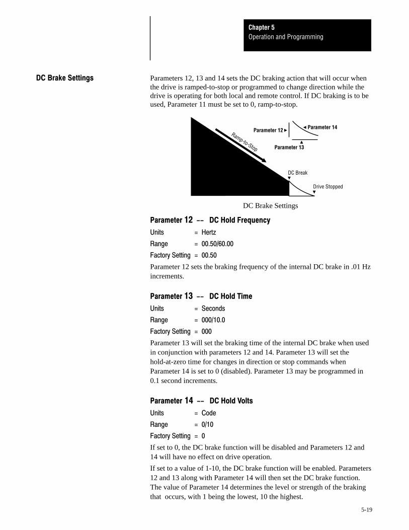
- Parameters 12, 13 and 14 sets the DC braking action that will occur whenthe drive is ramped-to-stop or programmed to change direction while thedrive is operating for both local and remote control. If DC braking is to beused, Parameter 11 must be set to 0, ramp-to-stop.
DC Brake Settings
Ramp-to-Stop
DC Break
Drive Stopped
Parameter 12
Parameter 13
Parameter 14
,. *+#
./
'(0'
'(
Parameter 12 sets the braking frequency of the internal DC brake in .01 Hzincrements.
,/ 0
'
Parameter 13 will set the braking time of the internal DC brake when usedin conjunction with parameters 12 and 14. Parameter 13 will set thehold-at-zero time for changes in direction or stop commands whenParameter 14 is set to 0 (disabled). Parameter 13 may be programmed in0.1 second increments.
,
If set to 0, the DC brake function will be disabled and Parameters 12 and14 will have no effect on drive operation.
If set to a value of 1-10, the DC brake function will be enabled. Parameters12 and 13 along with Parameter 14 will then set the DC brake function.The value of Parameter 14 determines the level or strength of the brakingthat occurs, with 1 being the lowest, 10 the highest.
Operation and ProgrammingChapter 5
5-20
"1 Important: The maximum allowable drive output frequency will bedetermined by the lowest programmed value of any of the followingparameters:
• Parameter 3 Frequency Range
• Parameter 15 Maximum Frequency
• Parameter 51 Upper Frequency Clamp
• Parameter 53 Bias Frequency –– If Parameter 53 is Higher ThanParameter 54
• Parameter 54 Gain Frequency –– If Parameter 54 is Higher ThanParameter 53
"1
100% of Output Frequency0%
0% Parameter 16
100% of Output Voltage
noitareleccA
Parameter 15
0%0% 100% of Output Frequency
Parameter 15 = Parameter 16
100% of Output Voltage
noitareleccA
Operation and ProgrammingChapter 5
5-21
,"1*+#
./
(''
0'
If Parameter 3 is set to 50 or 60, the drive will use the lower of the valuesset by Parameters 3 and 51 as the maximum drive output frequency.Parameter 15 will have no effect on drive operation.
If Parameter 3 is set to FF, the drive will use the lower of the values set byParameters 15 and 51 as the maximum drive output frequency.
From 50.00-100.0 Hz, this parameter sets the value of MaximumFrequency in .01 Hz increments.
From 100.0-400.0 Hz, this parameter sets the value of MaximumFrequency in 0.1 Hz increments.
,!*+#
./
('('
0'
The value set by Parameter 16 Base Frequency will be the point wheremaximum output voltage is applied to the motor when Parameter 3 is set toFF. If Parameter 3 is set to either 50 or 60 Hz, that will be the basefrequency that the drive uses.
From 50.00-100.0 Hz, this parameter sets the value of Base Frequency in.01 Hz increments.
From 100.0-250.0 Hz, this parameter sets the value of Base Frequency in0.1 Hz increments.
Operation and ProgrammingChapter 5
5-22
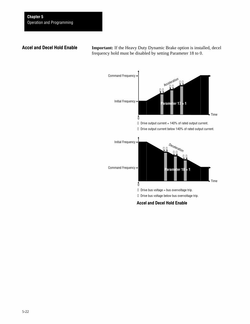
2 '( Important: If the Heavy Duty Dynamic Brake option is installed, decelfrequency hold must be disabled by setting Parameter 18 to 0.
2 '(
➊ Drive output current = 140% of rated output current.
➋ Drive output current below 140% of rated output current.
0
Initial Frequency
noitareleccA
Time
Command Frequency
➊ ➋
Parameter 17 = 1
➊➋
➊➋
0
Command Frequency
Time
Initial Frequency
➋➊
Deceleration
Parameter 18 = 1
➊ Drive bus voltage = bus overvoltage trip.
➋ Drive bus voltage below bus overvoltage trip.
➋➊
➋➊
Operation and ProgrammingChapter 5
5-23
,32 *+#
To help avoid drive nuisance trips, this parameter enables or disables driveacceleration during high current conditions.
When set to 0, accel stall protection is off. During drive acceleration,should drive output current rise above 140% of rated drive output current,the drive will trip.
When set to 1, accel stall protection is on. During acceleration, the drivewill hold the accel ramp for 60 seconds should drive output current riseabove 140% of rated drive output current. If output current does not fallbelow 140% after 60 seconds, the drive will trip.
,4 *+#
To help avoid drive nuisance trips, this parameter enables or disables drivedeceleration during overvoltage conditions.
When set to 0, decel stall protection is off. During drive deceleration,should drive bus voltage rise above the Over Voltage values listed below,the drive will trip.
Drive Input Voltage Decel Stall Over Voltage Trip200/208/230V AC 380V DC 430V DC380/415/460V AC 760V DC 820V DC
When set to 1, decel stall protection is on. During deceleration, the drivewill hold the decel ramp at one frequency until bus voltage drops below theDecel Stall values listed above.
Important: If Parameter 18 Decel Frequency Hold is set to 1 (On), anoverhauling load may cause the decel ramp to hold at one frequency for anextended period. This may cause ramp-to-stop commands to appear to benon-functional.
Operation and ProgrammingChapter 5
5-24
*+# ,)*+#
212 % '(
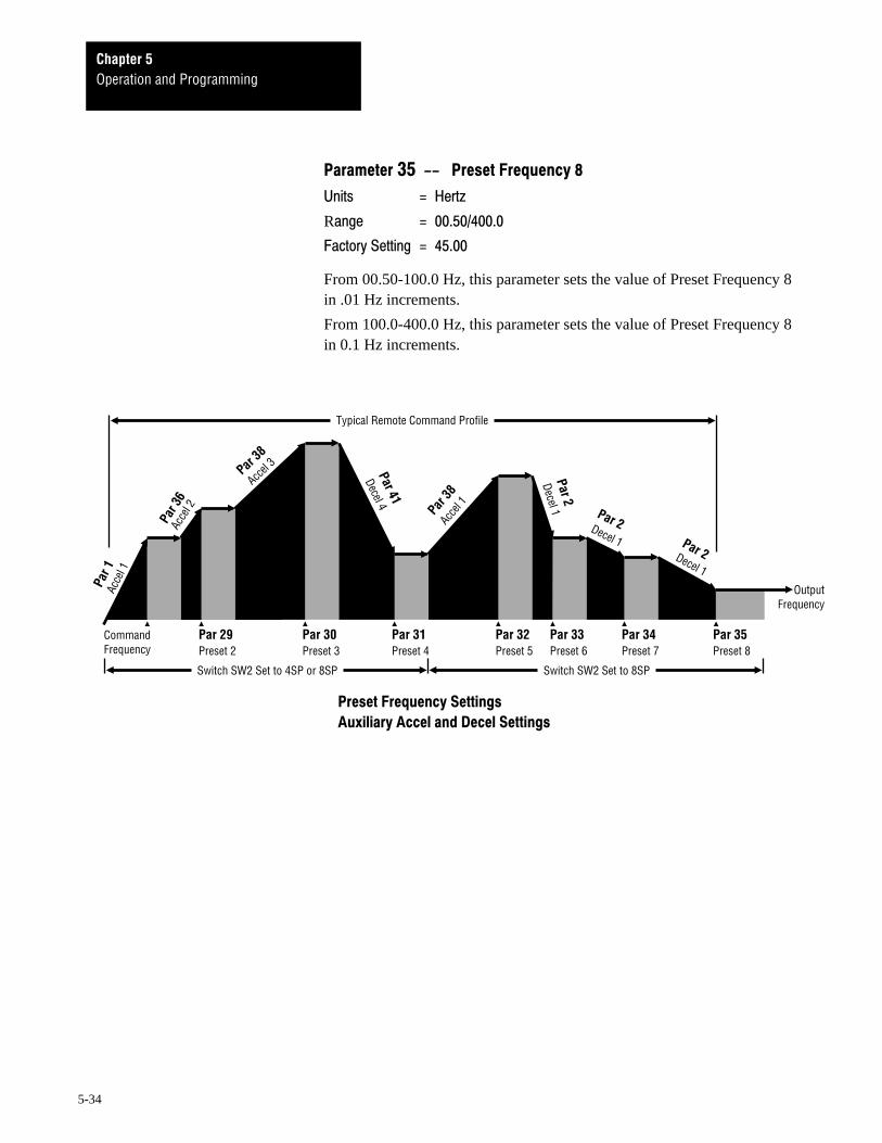
This parameter enables or disables the selection of preset drive frequencies,auxiliary drive preset accel and decel times, or both. To allow drive presetfrequencies and/or aux accel and decel times to be selected, externalswitches must be connected to the Control and Signal Wiring TerminalBlock as detailed in Chapter 4.
Preset frequencies are set by Parameters 29-35. Auxiliary accel and deceltimes are set by Parameters 36-41. External switches connected to theControl and Signal Wiring Terminal Block are enabled or disabled asexplained below and in the Preset Frequency and Aux Accel/Decel EnableTables on pages 5-20 –– 5-22.
1. Switch 5. on the Control Board is factory set to 4SP. When set to 4SP,two external switches may be connected to the drive. In addition to thestandard accel and decel rates set by Parameters 1 and 2, switches S1and S2 may then be used to select three additional accel rates, threeadditional decel rates, and four preset speeds, as programmed byParameters 29-31 and 36-41.
2. When switch 5. on the Control Board is set to 8SP, a total of threeexternal switches may be connected to the drive. In addition to thestandard accel and decel rates set by Parameters 1 and 2, switches S1, S2and S3 may then be used to select three additional accel rates, threeadditional decel rates, and seven preset speeds, as programmed byParameters 20 and 29-41.
Parameter 19 settings.
When set to 0, only the preset frequency function is enabled. Externalswitches connected to the Control and Signal Wiring Terminal Block canonly be used to select preset frequencies.
When set to 1, only the auxiliary accel and decel function is enabled.External switches connected to the Control and Signal Wiring TerminalBlock can only be used to select auxiliary accel and decel times.
When set to 2, both the preset frequency function and the auxiliary acceland decel function is enabled. External switches connected to the Controland Signal Wiring Terminal Block can be used to select both presetfrequencies and auxiliary accel and decel times.
Operation and ProgrammingChapter 5
5-25
.0,%&
This parameter selects the control function of switch S3 when threeexternal switches are connected to the Control and Signal Wiring TerminalBlock.
Parameter 20 settings.
When set to 0, external switches S1, S2 and S3 connected to the Controland Signal Wiring Terminal Block can be used to select Preset Frequencies2-8 and Accel/Decel Times 2-4.
When set to 1, external switches S1 and S2 connected to the Control andSignal Wiring Terminal Block can be used to select Preset Frequencies 2-4and Accel/Decel Times 2-4. If a third switch is installed, switch S3 is usedto remotely reset the drive should a drive fault occur.
As shown in Figure 4-5 in Chapter 4 ––
67,)8.
59
'1 '1
:95. :9, :9.
09
! )
! ) !12&3"243"
! ) !1 2&3" 243"
! ) ) !12&3"243"
67,)8,
59
'1 '1
:95. :9, :9.
09
! )
! ) &3"243"
! ) &3" 243"
! ) ) &3"243"
67,)8
59
'1 '1
:95. :9, :9.
09
! )
! ) !1
! ) !1
! ) ) !1
Operation and ProgrammingChapter 5
5-26
As shown in Figure 4-5 in Chapter 4 ––
67,)8. .8
59
'1 '1 '1
:95. :9, :9. :9/
09
*! )
*! ) !12&3"243"
*! ) !1 2&3" 243"
*! ) ) !12&3"243"
*! ) !1(2&3"243"
*! ) ) !102&3"243"
*! ) ) !1#2&3"243"
*! ) ) ) !1*2&3"243"
67,)8, .8
59
'1 '1 '1
:95. :9, :9. :9/
09
*! )
*! ) &3"243"
*! ) &3" 243"
*! ) ) &3"243"
*! ) &3"243"
*! ) ) &3"243"
*! ) ) &3"243"
*! ) ) ) &3"243"
67,)8 .8
59
'1 '1 '1
:95. :9, :9. :9/
09
*! )
*! ) !1
*! ) !1
*! ) ) !1
*! ) !1(
*! ) ) !10
*! ) ) !1#
*! ) ) ) !1*
Operation and ProgrammingChapter 5
5-27
As shown in Figure 4-5 in Chapter 4 ––
67,)8. .8,
59
'1 '1 '1
:95. :9, :9. :9/
09
*! )
*! ) !12&3"243"
*! ) !1 2&3" 243"
*! ) ) !12&3"243"
*! ) "
*! ) ) !12&3"243"2"
*! ) ) !1 2&3" 243" 2"
*! ) ) ) !12&3"243"2"
67,)8, .8,
59
'1 '1 '1
:95. :9, :9. :9/
09
*! )
*! ) &3"243"
*! ) &3" 243"
*! ) ) &3"243"
*! ) "
*! ) ) &3"243"2"
*! ) ) &3" 243" 2"
*! ) ) ) &3"243"2"
If Parameter 19 = 0 and Parameter 20 = 1When and and andControl Board External External ExternalSwitch SW2 Switch S1 Switch S2 Switch S3is Set to is Set to is Set to is Set to The Parameters Selected are
8SP OFF OFF OFF None
8SP ON OFF OFF Preset Frequency 2
8SP OFF ON OFF Preset Frequency 3
8SP ON ON OFF Preset Frequency 4
8SP OFF OFF ON Remote Fault Reset
8SP ON OFF ON Preset Frequency 2 + Remote Fault Reset
8SP OFF ON ON Preset Frequency 3 + Remote Fault Reset
8SP ON ON ON Preset Frequency 4 + Remote Fault Reset
Operation and ProgrammingChapter 5
5-28
216 -'( .,21 #6 -
To enable drive operation, terminal 16 and logic common at the Controland Signal Wiring Terminal Block must be jumpered. This parameter setsthe function of terminal 16 and logic common when a normally closedauxiliary interlock is installed in its place.
If set to 0, when the auxiliary contact opens:
• The drive will coast-to-stop, display fault &, and store the fault inFault Buffer Parameters 59-62.
• Fault Contact CR3 on the Control Board will change state to provide afault signal at terminals 22-24 at the Control and Signal Wiring TerminalBlock.
If set to 1, when the auxiliary contact opens:
• The drive will coast-to-stop and display &. Since & is not a fault, itwill not be stored in Fault Buffer Parameters 59-62.
• Since& is not a fault, Fault Contact CR3 on the Control Board will notchange state to provide a fault signal at terminals 22-24.
Operation and ProgrammingChapter 5
5-29
..&,
This parameter sets the function of drive supplied contact CR1. CR1 is anormally open contact located at terminals 19 and 20 on the Control andSignal Wiring Terminal Block.
If set to 1, the N.O contact will close when the drive is within ± 2 Hz of therun or jog set speed.
If set to 2, the N.O contact will close when the drive is at 140% of rateddrive output current or 125% of the current set in Parameter 7.
If set to 3, the N.O contact will close when the run or jog output frequencyis greater than the CR1 Frequency set by Parameter 24.
./&.
This parameter sets the function of drive supplied contact CR2. CR2 is anormally open contact located at terminals 20 and 21 on the Control andSignal Wiring Terminal Block.
If set to 0, the N.O contact will close when the drive receives a run or jogstart signal.
If set to 1, the N.O contact will close when the drive is within ± 2 Hz ofrun or jog set speed.
If set to 2, the N.O contact will close when the drive is at 140% of rateddrive output current or 125% of the current set in Parameter 7.
If set to 3, the N.O contact will close when the run or jog output frequencyis greater than the CR2 Frequency set by Parameter 25.
Operation and ProgrammingChapter 5
5-30
.&,*+#
./
'('
'(
This parameter sets the frequency that will cause drive supplied contactCR1 to close when Parameter 22 is set to 3.
From 00.50-100.0 Hz, this parameter sets the value of CR1 Frequency in.01 Hz increments.
From 100.0-400.0 Hz, this parameter sets the value of CR1 Frequency in.1 Hz increments.
.&.*+#
./
'('
'(
This parameter sets the frequency that will cause drive supplied contactCR2 to close when Parameter 23 is set to 3.
From 00.50-100.0 Hz, this parameter sets the value of CR2 Frequency in.01 Hz increments.
From 100.0-400.0 Hz, this parameter sets the value of CR2 Frequency in.1 Hz increments.
Operation and ProgrammingChapter 5
5-31
; .!;*+#
./
'('
'
This parameter sets the jog frequency (speed) that the drive will use whenit receives either a local or remote jog command. Jog frequency may be setin .01 Hz increments. Whenever the drive receives a jog command, AccelFrequency Hold, Decel Frequency Hold, and Current Limit functions aredisabled.
.3;2 0
0
'(
This parameter sets the time it takes the drive to accelerate to the jogfrequency set in Parameter 26. If set to 0000, the drive will enter 40 ms butdisplay 0000.
From 000.1-1000 seconds, sets the Jog Accel Time in 0.1 secondincrements.
From 1000-1600 seconds, sets the Jog Accel Time in 1 second increments.
.4; 0
0
'(
This parameter sets the time it takes the drive to decelerate to 0. If set to0000, the drive will enter 40 ms but display 0000.
From 000.1-1000 seconds, sets the Jog Decel Time in 0.1 secondincrements.
From 1000-1600 seconds, sets the Jog Decel Time in 1 second increments.
Operation and ProgrammingChapter 5
5-32
*+# Auxiliary Preset Frequencies are enabled or disabled by Parameters 19 and20. Individual Preset Frequency settings are selected by setting switchesS1, S2 and/or S3 as shown in Parameters 19 and 20.
.)*+#.
./
'('
'
From 00.50-100.0 Hz, this parameter sets the value of Preset Frequency 2in .01 Hz increments.
From 100.0-400.0 Hz, this parameter sets the value of Preset Frequency 2in 0.1 Hz increments.
/*+#/
./
'('
'
From 00.50-100.0 Hz, this parameter sets the value of Preset Frequency 3in .01 Hz increments.
From 100.0-400.0 Hz, this parameter sets the value of Preset Frequency 3in 0.1 Hz increments.
/,*+#
./
'('
'
From 00.50-100.0 Hz, this parameter sets the value of Preset Frequency 4in .01 Hz increments.
From 100.0-400.0 Hz, this parameter sets the value of Preset Frequency 4in 0.1 Hz increments.
Operation and ProgrammingChapter 5
5-33
/.*+#
./
'('
('
From 00.50-100.0 Hz, this parameter sets the value of Preset Frequency 5in .01 Hz increments.
From 100.0-400.0 Hz, this parameter sets the value of Preset Frequency 5in 0.1 Hz increments.
//*+#!
./
'('
('
From 00.50-100.0 Hz, this parameter sets the value of Preset Frequency 6in .01 Hz increments.
From 100.0-400.0 Hz, this parameter sets the value of Preset Frequency 6in 0.1 Hz increments.
/*+#3
./
'('
('
From 00.50-100.0 Hz, this parameter sets the value of Preset Frequency 7in .01 Hz increments.
From 100.0-400.0 Hz, this parameter sets the value of Preset Frequency 7in 0.1 Hz increments.
Operation and ProgrammingChapter 5
5-34
/*+#4
./
R '('
('
From 00.50-100.0 Hz, this parameter sets the value of Preset Frequency 8in .01 Hz increments.
From 100.0-400.0 Hz, this parameter sets the value of Preset Frequency 8in 0.1 Hz increments.
*+#
21 #2
CommandFrequency
Par 29Preset 2
OutputFrequency
Par 30Preset 3
Par 31Preset 4
Par 32Preset 5
Par 33Preset 6
Par 34Preset 7
Acce
l 1
Acce
l 2
Accel 3
Decel 4
Decel 1
Decel 1Decel 1
Acce
l 1
Par 35Preset 8
Par 3
6
Par 1
Par38
Par 41
Par 38
Par 2
Par 2Par 2
Typical Remote Command Profile
Switch SW2 Set to 4SP or 8SP Switch SW2 Set to 8SP
Operation and ProgrammingChapter 5
5-35
Auxiliary Accel and Decel Times are enabled or disabled by Parameters 19and 20. Individual Accel and Decel Parameter settings are selected bysetting switches S1, S2 and/or S3 as shown in Parameters 19 and 20
Each auxiliary accel time determines a time that it will take the drive toaccelerate over a 60 Hz frequency change. From 0 to 0.5 Hz, any auxiliaryaccel rate set is effectively zero. From 0.5 Hz to maximum outputfrequency, the accel rate set by each auxiliary accel time will remainconstant. For each accel time, the total time it will take the drive toaccelerate from an initial frequency to a new command frequency is:Total time = (New Command Frequency – Initial Frequency) × (AccelTime) ÷ 60.
From 000.1-1000 seconds, these parameters set the values of Accel Time 2,3 and 4 in 0.1 second increments.
From 1000-1600 seconds, these parameters set the value of Accel Time 2,3 and 4 in 1 second increments.
Each auxiliary decel time determines a time that it will take the drive todecelerate and ramp-to-stop over a 60 Hz change in frequency. From 0.5 to0 Hz, the accel rate is non-linear and set by either DC injection braking orthe DC dynamic brake if it is installed. From maximum output frequencyto 0.5 Hz, the accel rate set by Parameter 2 will remain constant. For eachdecel time, the total time it will take the drive to decelerate from an initialfrequency to a new command frequency is:Total time = (New Command Frequency – Initial Frequency) × (AccelTime) ÷ 60.
From 000.1-1000 seconds, these parameters set the values of Decel Time 2,3 and 4 in 0.1 second increments.
From 1000-1600 seconds, these parameters set the value of Decel Time 2,3 and 4 in 1 second increments.
Operation and ProgrammingChapter 5
5-36
!"#$ !"#$
To help avoid undesirable mechanical resonance, Parameters 42-44prevents the drive from running at one, two or three specific frequencies.Although the drive will use these frequencies when accelerating ordecelerating, they cannot be set as ”running” frequencies by any driveparameter. The drive will stay slightly above or slightly below thesefrequencies if the frequency values are entered. If a Skip Frequency valueof 0000 is selected, the skip frequency function of that parameter isdisabled.
From 00.50-100.0 Hz, Parameters 42-44 sets the Skip Frequencies in .01Hz increments.
From 100.0-400.0 Hz, Parameters 42-44 sets the Skip Frequencies in 0.1Hz increments.
!"#$
Parameter44
Parameter42
Parameter43
Acceler
ation
Parameter42
Parameter44
Parameter43
Deceleration
CommandFrequency
Parameter 45Parameter 45
Operation and ProgrammingChapter 5
5-37
%!"#$&
Parameter 45 allows each of the individual Skip Frequencies set inParameters 42-44 to be expanded into three bands of skip frequencies in2-20 Hz increments.
Setting a Skip Frequency Band value of 0 will disable the Skip FrequencyBand function, but not individual Skip Frequency values set by Parameters42-44.
Setting a Skip Frequency Band value other than 0 will enable SkipFrequency values and expand their range by 2 Hz. For example, ifParameter 45 is set to 1, a Skip Frequency value set by Parameter 42, 43 or44 will expand to a band that includes the Skip Frequency value with anadditional 1 Hz band on either side. If set to 10, a Skip Frequency value setby Parameter 42, 43 or 44 will expand to a band that includes the SkipFrequency value with an additional 10 Hz band on either side.
Important:
1. If the drive is programmed with a Parameter 3 Frequency Range and/orParameter 15 Maximum Frequency value that falls within a skipfrequency bandwidth, the drive will operate only through the non-skipfrequencies below Parameters 3 and 15.
2. If the drive is programmed with a Parameter 51Upper Frequency Clampvalue that falls within a skip frequency bandwidth, the drive will operateonly through the non-skip frequencies below Parameter 51, then jump tothe Parameter 51 value at a maximum speed command.
3. If Parameters 3, 15 and 51 are all within the skip frequency bandwidth,the drive will operate only though the non-skip frequencies below thelowest value set by Parameters 3, 15 and 51.
Operation and ProgrammingChapter 5
5-38
'( '(
Should drive current rise above 140% of rated drive output current, thedrive will attempt to limit current for one minute. Parameter 46 sets thefrequency foldback rate used to decrease current in .1 second increments.Frequency foldback allows the drive to ramp output frequency down farenough to temporarily eliminate an overcurrent condition. When Parameter46 is set to 00, the Current Limit function set by Parameter 46 is disabledand the drive’s overcurrent feature will trip the drive should current riseabove 200%.
'(
200%
0
Drive Output Current
➊ % of Drive Overcurrent
➋ Drive Output Frequency Decel Ramp
➌ Parameter 46 = 0.5 Seconds
➍ Parameter 46 = 1.0 Seconds
➎ Parameter 46 = 1.5 Seconds
➏ Parameter 46 = 0.0 Seconds
OVERCURRENT
140%
Time
➏ Drive Trips at 200%
DriveOperatingRange
DriveOperatingRange
DriveOperatingRange
OVERCURRENT
OVERCURRENT
DriveOperatingRange
➌
➊➋
➎➍
➊
➋
➊
➋
Operation and ProgrammingChapter 5
5-39
!ATTENTION: Auto restart operation may only be used asoutlined in NFPA79, Paragraph 6-14 (exceptions 1-3) forspecialized applications. Equipment damage and/or personal injurymay result if the settings of Parameters 47-49 are used in aninappropriate application.
)*
)+()*
This parameter selects the drive restart action taken if input power isinterrupted and restored within 100 ms –– However –– restart settings 1and 2 in Parameter 48 will override any settings made in Parameter 47.
• When set to 0, the drive will restart and ramp to the last selected speed–– but only for 2-wire external control.
• When set to 1, Power Loss Restart is disabled for both 2 and 3-wirecontrol schemes. The drive will not restart until the fault is cleared byfirst issuing a stop command, then a start command. The drive will thenrestart and ramp to the last selected speed.
• 2 defines the drive restart action for 2-wire external control. Once thedrive receives a start command, the drive will start and ramp to the lastselected speed but only after the initial waiting time set by Parameter 49.
Should an fault occur or ! message appear, the drive will restartand ramp to the last selected speed after the initial waiting time set byParameter 49 without reissuing a start command.
• 3 defines the drive restart action for both 2 and 3-wire control. Once thedrive receives a start command, the drive will start and ramp to the lastselected speed but only after the initial waiting time set by Parameter 49.
Should an fault occur or ! message appear, the drive will notrestart until the fault or message has been cleared by first issuing a stopcommand, then a start command. Once cleared, the drive will start andramp to the last selected speed after the initial waiting time set byParameter 49.
Operation and ProgrammingChapter 5
5-40
* ,-*
For all control schemes, this parameter selects the drive restart action takenif input power is interrupted and restored within 100 ms. Restart settings 1and 2 in Parameter 48 will override any settings made in Parameter 47.
• When set to 0, if power is removed for 15 ms, Ride-Thru Restart is
disabled and the drive will generate an fault. The drive will notrestart until the fault is cleared by first issuing a drive stop command,then a start command. The drive will then restart and ramp to the lastselected speed.
• When set to 1, if power is removed for 15 ms, the drive will generate an
fault. If power is restored within 100 ms (or longer depending onload), the drive will restart from zero speed, then ramp to the lastselected speed after the initial waiting time set by Parameter 49.
• When set to 2, if power is removed for 15 ms, the drive will generate an
fault. If power is restored within 100 ms (or longer depending onload), the drive will continue to operate at the selected speed. If longerthan 100 ms, the drive will restart only after the initial waiting time setby Parameter 49.
*
This parameter sets the time the drive will wait before acting on a restart
command after an LU fault has occurred. The value of Parameter 49 isselectable in 0.1 second increments.
Operation and ProgrammingChapter 5
5-41
()+ ."" Important: The maximum allowable drive output frequency will be#$'" determined by the lowest value programmed into the following parameters:
• Parameter 3 Frequency Range
• Parameter 15 Maximum Frequency
• Parameter 51 Upper Frequency Clamp
• Parameter 53 Bias Frequency –– If Parameter 53 is Higher ThanParameter 54
• Parameter 54 Gain Frequency –– If Parameter 54 is Higher ThanParameter 53
%()+#$'"
This parameter sets the minimum frequency or speed that the drive can beset to by any input control signal.
From 00.50-100.0 Hz, Parameter 50 sets the Lower Frequency Clamp in.01 Hz increments.
From 100.0-400.0 Hz, Parameter 50 sets the Lower Frequency Clamp in0.1 Hz increments.
Important: If an external potentiometer, a 0-5V DC, a 0-10V DC or a4-20mA frequency reference is required:
• For directly proportional applications, enable Parameter 52 and enter aminimum value of 00.50 for Parameter 53 if the Lower FrequencyClamp is to set the minimum frequency.
• For inverse follower applications, enable Parameter 52 and enter aminimum value of 00.50 for Parameter 54 if the Lower FrequencyClamp is to set the minimum frequency.
Operation and ProgrammingChapter 5
5-42
()+ .""#$'"
➊ Maximum Output Frequency
100% of Input Frequency Signal0%0
Parameter 50
Minimimum Frequency = 0.5
Parameter 51
noitareleccA
➊ Maximum Output Frequency = 50 Hz if Parameter 3 = 50 60 Hz if Parameter 3 = 60 Parameter 15 if Parameter 3 = FF
➊ Maximum Output Frequency
100% of Input Frequency Signal0%0
Parameter 50
Parameter 51
noitareleceD
Minimimum Frequency = 0.5
% .""#$'"
This parameter sets the highest frequency or speed that the drive can be setto by any input control signal, unless Parameter 15 (Maximum Frequency)or Parameter 3 (Frequency Range) has been set lower. If set to a valuehigher than Parameter 3 or 15, the value will be entered, but the drive willdefault to the lowest value set by Parameter 3 or 15 when operating.
From 00.50-100.0 Hz, Parameter 51 sets the Upper Frequency Clamp in.01 Hz increments.
From 100.0-400.0 Hz, Parameter 51 sets the Upper Frequency Clamp in0.1 Hz increments.
Operation and ProgrammingChapter 5
5-43
& / Important: The maximum allowable drive output frequency will bedetermined by the lowest programmed value of any of the followingparameters:
• Parameter 3 Frequency Range
• Parameter 15 Maximum Frequency
• Parameter 51 Upper Frequency Clamp
• Parameter 53 Bias Frequency –– If Parameter 53 is Higher ThanParameter 54
• Parameter 54 Gain Frequency –– If Parameter 54 is Higher ThanParameter 53
%& /01
This parameter enables or disables both the Bias and Gain Frequencies setby Parameters 53 and 54. Bias and Gain Frequencies allows a remote speedsignal to be used within a specific minimum and maximum frequencyrange. The Bias and Gain Frequencies may be used to provide a directly orinversely proportional 0-5V DC, 0-10V DC, 4-20 mA, or external speedpot signal at the Control and Signal Wiring Terminal Block.
If set to 0, the bias and gain function is disabled.
If set to 1, the bias and gain function is enabled.
If the 1333 is to produce 0 output speed at 0 external input signal:
• Parameter 9 Local/Remote Frequency must be set to remote.
• Parameter 52 Bias and Gain Enabled must be enabled.
• Parameter 53 Bias Frequency must be set to the minimum outputfrequency required.
• Parameter 54 Gain Frequency must be set to the maximum outputfrequency required.
If the 1333 is to produce maximum output speed at 0 external input signal:
• Parameter 9 Local/Remote Frequency must be set to remote.
• Parameter 52 Bias and Gain Enabled must be enabled.
• Parameter 53 Bias Frequency must be set to the maximum outputfrequency required.
• Parameter 54 Gain Frequency must be set to the minimum outputfrequency required.
Operation and ProgrammingChapter 5
5-44
& /
➊ 100% of Output Frequency
100% of Input Frequency Signal0%Parameter 53 = 0%
Acceleration When Bias Frequencyis Less Than Gaina Directly ProportionalInput Frequency Signalis Produced
Bias Frequency Less Than Gain
Parameter 54
➊ 100% of Output Frequency = 50 Hz if Parameter 3 = 50 60 Hz if Parameter 3 = 60 Paramer 15 if Parameter 3 = FF
➊ 100% of Output Frequency
100% of Input Frequency Signal
Bias Frequency Greater Than Gain
0%0%
Parameter 53
noitareleceD
When Bias Frequencyis Greater Than Gainan Inversely ProportionalInput Frequency Signalis Produced
Parameter 54
%&#$
From 00.50-400.0 Hz, Parameter 53 sets the Bias Frequency in .01 Hzincrements.
From 100.0-400.0 Hz, Parameter 53 sets the Bias Frequency in 0.1 Hzincrements.
%/#$
From 00.50-400.0 Hz, Parameter 54 sets the Gain Frequency in .01 Hzincrements.From 100.0-400.0 Hz, Parameter 54 sets the Gain Frequency in 0.1 Hzincrements.
Operation and ProgrammingChapter 5
5-45
2"3 %%#$2"4"5
"#$ %&'& '(' )
Range = 075/125
Factory Setting = 100
This parameter is used to calibrate an output frequency ammeter while thedrive is running. It may be set from 75-125% of the maximum outputsignal, 1 mA. The 1 mA signal is selected by setting switch SW1 on theControl Board to the 1 mA position.
%#$2"46)5
Units = % of Maximum Output Signal
Range = 075/125
Factory Setting = 100
This parameter is used to calibrate an output frequency voltmeter while thedrive is running. It may be set from 75-125% of the maximum outputsignal, 10V DC. The 10V DC signal is selected by setting switch SW1 onthe Control Board to the 10V DC position.
3))3) %3))"
This parameter sets one of three alternate monitoring modes that may beselected while the drive is running.
When set to 0, * –– monitor equivalent drive output current.
When set to 1, * –– monitor equivalent motor RPM.
When set to 2, * –– monitor drive control frequency.
%3)))
+
To allow motor RPM to be calculated and displayed when monitoring
mode * is selected, this parameter is used to enter the number of motorpoles.
Operation and ProgrammingChapter 5
5-46
7#3) % #&88
,
,
,
Parameters 59-62 will store the last (4) faults that the drive has encounteredin a cascading mode.
• Fault Buffer 0 will store the new fault.
• Fault Buffer 1 will store the fault from Fault Buffer 0.
• Fault Buffer 2 will store the fault from Fault Buffer 1.
• Fault Buffer 3 will store the fault from Fault Buffer 2.
6Chapter
6-1
The following startup procedure uses the Local Control and ProgrammingPanel to setup the drive. To guard against damage to equipment caused byincorrect or inappropriate parameter settings, steps 1-28 must be followedin order. Step 29 is provided to allow you to incorporate an external 2 or3-wire control scheme into your application.
!ATTENTION: Power must be applied to the drive with the coverremoved to perform certain startup procedures. Voltages on manycomponents are at incoming line potential or bus voltage. To avoidelectric shock hazard or damage to equipment, do not touch anydrive component other than those specified in the startupprocedure.
!ATTENTION: Become familiar with the equipment and readthrough the wiring, speed selection and adjustment sections beforeattempting to perform the startup procedures. Adjustments may berequired to meet specific load characteristics or operatorpreference.
Exercise extreme care when performing any task on the drive.Failure to do so may result in electric shock or equipment damage.
As shown on the next page, a DC bus neon light at the top of the1333 has been provided to provide visual indication that busvoltage is present. Bus voltage may be verified by using avoltmeter and measuring the voltage between +BUS and –BUS onthe Power Terminal Block. Do not attempt to service the drive until2 minutes after the neon light has extinguished and bus voltage hasdischarged to zero volts.
StartupChapter 6
6-2
Important:
1. Power must be applied to the drive when viewing or changing 1333parameters. Previous programming may effect the drive status whenpower is applied.
2. Remote circuits may be connected to the Control and Signal WiringTerminal Block on the Main Control Board. Confirm that all circuits arein a de-energized state before applying power.
3. User supplied voltages may exist at the Control and Signal WiringTerminal Block even when power is not applied to the drive.
4. If you cannot complete a procedure, immediately refer to Appendix B— Preventive Maintenance and Troubleshooting Common DriveProblems. Do not proceed. Determine the cause of the problem andcorrect the problem first, then return to the startup procedure.
!"
#
""
$
%" &'(()*+',-.$/0,,'+-1
StartupChapter 6
6-3
!
"#
!!"
$ "
%! &'(()*+',*-$./0/'/*1
1333 parts, switches and terminal blocks shown in Figures 6-1, 6-2 and 6-3are referenced throughout the Initial Operation, Function Checks, Functionand Final Settings Sections of this chapter.
StartupChapter 6
6-4
Verify that AC line power at the disconnect device is within the rated valueof the drive nameplate data. Drive nameplate and alternate voltage ratingsare explained in Chapter 2 — Drive Identification.
Remove and lock out all incoming power to the drive. Remove the drivecover and disconnect the motor leads from terminals U/
T1, V/
T2, W/
T3 atthe Power Terminal Block. Insulate the exposed wires to prevent accidentalcontact with other drive components.
If an auxiliary interlock is not installed at the Control and Signal WiringTerminal Block, verify that the spare jumper provided with the drive isinstalled between terminals 16 and 17.
Replace the drive cover and tighten both thumbscrews. Apply power to thedrive and verify that no faults are displayed.
• Both the main and mode displays should immediately light.
• The main display should read . If the main display indicates or
, an incorrect voltage is being applied to the drive.
• The mode display should read . to allow control of the drive from theLocal Control and Programming Panel. If not, refer to Chapter 5 ––Operation and Programming to change Parameters 8 and 9 to localcontrol.
Important: Steps 5-15d are based on factory parametersettings. The function groups listed, reference the same parameters asgrouped in Chapter 5 and Appendix C. If the drive has been previouslycommissioned, parameter settings may not be compatible with this startupprocedure. Drive status and fault conditions will be unpredictable whenpower is first applied.
To obtain the proper results, initially change all parameter values to thefactory settings listed on the drive cover label. If it is required to change aparameter, you will be instructed to do so.
StartupChapter 6
6-5
!
" #$
" #$
" %#$
"&#$
"'
" (
" #$
" #$
"&#$
"'
)*+,+-.#/011+123
1,4& $
5 )
Start the drive by pressing either directional start pushbutton. Thepushbutton will light. Press and hold the increment pushbutton and watchthe display increase. Release thew pushbutton when the display reaches Hz or maximum speed.
* )
Press the select pushbutton once. The main display will flash and show thelast manual set speed entered.
Press the select pushbutton again. . will be shown in the mode display,drive output amps in the main display, as set by Parameter 57.
Press the select pushbutton again. The mode display will flash and show. to indicate the parameter being viewed, and the main display will show
, the accel time set by Parameter 1.
Press the pushbutton again and Hz will again be displayed.
647 $
! )
Press the other directional start pushbutton. The pushbutton will light andthe drive display will ramp down to Hz within the decel time set by
Parameter 2, then immediately ramp up to Hz, the maximum speedpresently programmed by Parameter 3, within the accel time set byParameter 1. Reversing is enabled or disabled by Parameter 10.
StartupChapter 6
6-6
8,4& $ (9:'& )
Press the select pushbutton once. The main display will again flash andshow the last manual set speed entered. Using the increment, decrementand shift pushbuttons, any value between 00.50 (the lower frequency clampset by Parameter 50), and 60.00 Hz can be selected.
Select a value and press the enter key. The drive will either accel within theaccel time set by Parameter 1, or decel within the decel time set byParameter 2, to a value within these limits. Had Parameter 51 been set to avalue lower than 60.00 Hz, the upper frequency clamp would be thehighest frequency the drive could reach.
; )
Press the stop pushbutton to stop the drive. The drive display will rampdown to zero within the decel time set by Parameter 2. Had Parameter 11been set to 1, the drive would have been set to coast-to-stop and Parameter2 would have no affect on stopping time.
-<) )
Press the shift pushbutton once and . will be shown in the mode display.Press and hold either directional start pushbutton. The pushbutton will lightand the drive display will ramp up to Hz, or the maximum jog speedset by Parameter 26, within the jog accel time set by Parameter 27. Releasethe directional start pushbutton and the drive will ramp back down to Hz at the jog decel time set by Parameter 28. Once fully stopped, the
drive will display .
!5' $
7&'
Start the drive. If an external auxiliary interlock has been installed betweenterminals 16 and 17 at the Control and Signal Wiring Terminal Block, openthe interlock. will be shown at the main display, indicating an auxiliaryinterlock fault.
• Press the stop pushbutton to clear the fault.
• Press the select pushbutton three times to access the parameter display.
• Select Parameter 59. Fault Buffer 0 will display , the last faultreceived by the drive.
If Parameter 21 had been set to 1, the drive would have displayed at
the main display, indicating an auxiliary stop. An is not a fault, andtherefore not stored in memory.
StartupChapter 6
6-7
7 )
Stop the drive. Remove and lock out all incoming power to the drive, thenremove the drive cover.
Reapply power and start the drive. N.O. contact CR2 (terms. 20 & 21 onthe Control and Signal Wiring Terminal Block) will close as presentlyprogrammed by Parameter 23. Once the drive is within ± 2 Hz of set speed,N.O. contact CR1 (terminals 19 & 20 on the Control and Signal WiringTerminal Block) will close since Parameter 24 is presently set to 1.
!4 )
!ATTENTION: Auto restart operation may only be used asoutlined in NFPA79, Paragraph 6-14 (exceptions 1-3) forspecialized applications. Equipment damage and/or personal injurymay result if the settings of Parameters 47-49 are used in aninappropriate application.
To properly program the drive to restart when required demands thatParameters 47-49 be coordinated correctly. When Parameter 48 is set to 1or 2, it will override any setting made in Parameter 47. Likewise the restarttime set in Parameter 49 will affect the restart actions taken by bothParameters 47 and 48.
$!4 )
If Power Loss Restart is required, set Parameters 1 and 3.
Stop the drive.
• Change Parameter 47 from 1 to 3.
• Change Parameter 49 from 000.1 seconds to 10.00 seconds.
Press the start pushbutton. The directional start pushbutton LED willimmediately light. After 10 seconds the drive will ramp up to 60 Hz andthe main display will show .
Remove then reapply incoming power to the drive at the disconnect devicewithin 100 ms. will be shown at the main display indicating a powerfault. Press the stop pushbutton to clear the fault, then the start pusbutton tostart the drive. Since Parameter 49 has been changed, the drive will notrestart for 10 seconds.
• Had the drive been configured for 2-wire control and Parameter 47 set to0, without clearing the fault, the drive would have automaticallyrestarted and ramped up to 60 Hz without a waiting time.
• Had the drive been configured for 2-wire control and Parameter 47 set to3, without clearing the fault, the drive would have automaticallyrestarted and ramped up to 60 Hz after 10 seconds.
StartupChapter 6
6-8
!4 )
If Ride-Thru Restart is required, set Parameters 1 and 3.
Stop the drive.
• Change Parameter 48 from 0 to 1.
Remove then reapply incoming power to the drive at the disconnect devicewithin 100 ms. will be shown at the main display indicating a powerfault. The directional start pushbutton LED will immediately light. After10 seconds, the drive will ramp up to 60 Hz and the main display willshow .
Stop the drive.
• Change Parameter 48 from 1 to 2.
Remove then reapply incoming power to the drive at the disconnect devicewithin 100 ms. will be shown at the main display indicating a powerfault. The directional start pushbutton LED will immediately light. After10 seconds, the main display will immediately show . The driveaccel ramp has been eliminated and the drive will restart at the lastcommanded speed, 60 Hz.
Stop the drive and return Parameters 47-49 to their factory settings.
=> )
If an external 10kΩ, 2W potentiometer, 0-5V DC, 0-10V DC or 4-20 mAsignal is connected to the drive, the bias and gain settings should beverified.
• Change Parameter 52 from 0 to 1 to enable the bias and gain function.
• Change Parameter 53 from 00.50 to 60.00.
• Change Parameter 54 from 60.00 to 00.50.
With zero speed signal applied to the drive, start the drive. Apply thesmallest speed signal possible. The drive display will immediately ramp upto Hz. Apply maximum signal to the drive. The drive display will
ramp down to Hz. This is because an inversely proportional signalhas been sent to the drive. Stop the drive and return Parameters 52-54 totheir factory settings.
StartupChapter 6
6-9
1#:'!5!, $
If external switches have been connected to the Control and Signal WiringTerminal Block as detailed in Chapter 5, preset frequencies as well asauxiliary accel and decel times can be checked.
1$#:'!5!, $
Enable Auxiliary Accel/Decel Settings
Stop the drive and depress the lock button to allow programming. SetParameter 19 to 2. By setting Parameter 19 to 2, auxiliary accel/decel timeswill be enabled and can be checked simultaneously with preset speeds.
1#:'!5!, $
If two preset speed switches have been installed, verify that switchSW2 is set to 4SP.
• Closing switch S1 and opening switch S2 will force the drive to20.00 Hz, the Preset Frequency 2 value set by Parameter 29, within the2nd auxiliary accel time set by Parameter 36, or the 2nd auxiliary deceltime set by Parameter 37.
• Opening switch S1 and closing switch S2 will force the drive to30.00 Hz, the Preset Frequency 3 value set by Parameter 30, within the3rd auxiliary accel time set by Parameter 38, or the 3rd auxiliary deceltime set by Parameter 39.
• Closing switches S1 and S2 will force the drive to 40.00 Hz, the PresetFrequency 4 value set by Parameter 31, within the 4th auxiliary acceltime set by Parameter 40, or the 4th auxiliary decel time set byParameter 41.
StartupChapter 6
6-10
1#:'!5!, $
If three preset speed switches have been installed, verify that switchSW2 is set to 8SP.
• Closing switch S1 and opening switches S2 and S3 will force the driveto 20.00 Hz, the Preset Frequency 2 value set by Parameter 29, withinthe 2nd auxiliary accel time set by Parameter 36, or the 2nd auxiliarydecel time set by Parameter 37.
• Opening switches S1 and S3 and closing switch S2 will force the driveto 30.00 Hz, the Preset Frequency 3 value set by Parameter 30, withinthe 3rd auxiliary accel time set by Parameter 38, or the 3rd auxiliarydecel time set by Parameter 39.
• Closing switches S1 and S2 and opening switch S3 will force the driveto 40.00 Hz, the Preset Frequency 4 value set by Parameter 31, withinthe 4th auxiliary accel time set by Parameter 40, or the 4th auxiliarydecel time set by Parameter 41.
• Opening switches S1 and S2 and closing switch S3 will force the driveto 15.00 Hz, the Preset Frequency 5 value set by Parameter 32, withinthe 4th auxiliary accel time set by Parameter 40, or the 4th auxiliarydecel time set by Parameter 41.
• Opening switch S2 and closing switches S1 and S3 will force the driveto 25.00 Hz, the Preset Frequency 6 value set by Parameter 33, withinthe 4th auxiliary accel time set by Parameter 40, or the 4th auxiliarydecel time set by Parameter 41.
• Opening switch S2 and closing switches S1 and S3 will force the driveto 35.00 Hz, the Preset Frequency 7 value set by Parameter 34, withinthe 4th auxiliary accel time set by Parameter 40, or the 4th auxiliarydecel time set by Parameter 41.
• Closing switches S1, S2 and S3 will force the drive to 45.00 Hz, thePreset Frequency 8 value set by Parameter 35, within the 4th auxiliaryaccel time set by Parameter 40, or the 4th auxiliary decel time set byParameter 41.
StartupChapter 6
6-11
!ATTENTION: The following steps may cause motor rotation inan unknown direction. To guard against equipment damage, alwaysdisconnect the motor from the load before proceeding.
)
?+
Important: The remaining steps are Function Settings that reference thesame parameters as grouped in Chapter 5 –– Operation and Programming.
*
Stop the drive and remove and lock out all incoming power to the drive.Remove the drive cover and reconnect the motor leads at terminals U/T1,V/T2,
W/T3 at the Power Terminal Block.
6
Replace the drive cover and tighten both thumbscrews. Apply power to thedrive and verify that no faults are displayed.
• Both the main and mode displays should immediately light.
• The main display should read . If the main display indicates or
, an incorrect voltage is being applied to the drive.
• The mode display should read . to allow control of the drive from theLocal Control and Programming Panel. If not, refer to Chapter 5 tochange Parameters 8 and 9 to local control.
8@++7 )
7# )
Set Parameters 3 and 4 to match your volts-per-Hertz curve and drivefrequency range requirements as detailed in Chapter 5.
If overload protection is not required, leave Parameter 6 set to 0. Ifoverload protection is required:
• Set Parameter 6 to correspond to the motor duty as outlined in Chapter 5.
• Set Parameter 7 to correspond to the rated amps on your motornameplate.
StartupChapter 6
6-12
) ;
Press the shift pushbutton once and . will be shown in the mode display.
?+ Press and release the directional start pushbutton that will be your forwardmotor direction. If the direction of motor rotation is incorrect:
• Remove input power, wait until the displays are no longer lit, thenremove the drive cover.
• Verify that the DC bus neon light is no longer lit and that bus voltage atthe +Bus and –Bus terminals of the power terminal block is zero.
• Interchange any two of the three motor leads at terminals U/T1, V/T2,
W/T3 at the Power Terminal Block.
• Replace the drive cover and tighten both thumbscrews. Apply power tothe drive and verify that no faults are displayed.
- )
If an external output ammeter or voltmeter is connected to the Control andSignal Wiring terminal block, the meter should be calibrated and switchSW1 should be set as detailed by Parameters 55 or 56 in Chapter 5.
StartupChapter 6
6-13
!ATTENTION: To avoid hazards of electrical shock or injuryfrom moving equipment, product, or process ingredients:
• Alert all personnel.
• Install all guards.
• Check operation of all safety devices.
• Be prepared to stop the motor immediately.
)
Disconnect and lock-out all power. Connect the motor to the load.
Before applying power, review the parameter descriptions in Chapter 5.Each parameter may have a significant effect on fundamental drive andmotor operation regardless of the control method used.
Apply power. Prepare to operate the drive and motor under actual controland load conditions. It is recommended to begin at low torque and speed.
Start the motor and run the machine or process to determine if parametersettings are acceptable for the application. If not, stop the drive and resetparameters. Refer to Chapter 5 to make parameter changes and record thechanges in Appendix C.
If Increased Motor Torque is Required at Startup
Increase the value of Parameter 5 in small increments.
Parameter 5 adds from 0 to 40% of the drive output voltage to the motor atlow drive frequencies, boosting motor torque at startup. DC boost can beadded to any volts-per-Hertz curve. The optimum DC boost setting is thelowest level that will permit satisfactory starting torque for the motor anddrive. Higher than optimum boost may produce unnecessary motor currentat low frequencies and contribute to motor overheating. Excessive boostmay even force the drive into an overcurrent condition.
If DC Braking is Required for Speed Changes, Reversing or to Stopthe Motor
Set Parameter 14 to 1 first.
When Parameter 14 is set to a value of 1-10, the drive’s DC brake functionwill be enabled. Parameters 12 and 13 along with Parameter 14 will thenset the DC brake function. The value of Parameter 14 determines the levelor strength of the braking that occurs, with 1 being the lowest, 10 thehighest.
StartupChapter 6
6-14
)
If Heavy Duty Dynamic Braking is to be Installed
If Heavy Duty Dynamic braking is required, set Parameters 11 and 14 to 0.
1
If Machine Resonance is Encountered
Set Parameters 42-45 to skip those frequencies which cause the machine toresonate.
*
If Nuisance Tripping is Encountered
Enable Parameters 17 and/or 18 to disable drive acceleration ordeceleration during high Bus current or voltage conditions.
6
If the Connected Load is an Overhauling Load
Set Parameter 18 to 0 to disable Decel Frequency Hold.
8
If a Different Running Monitor Mode is Required
Change Parameter 57 to:
• 0 to monitor drive output current.
• 1 to monitor equivalent motor RPM.
• 2 to monitor drive control frequency.
;
If an External 2 or 3-Wire Control Scheme is to be Used
• Connect the 2 or 3-wire controls as shown in Figure 4-3 and described inChapter 4.
• Set Parameter 8 to 1 for 2-wire control, 3 for 3-wire control.
• Repeat the startup procedure starting from step 1.
AAppendix
A-1
Bulletin 1332 and 1333 Options can be used with Series D drives. Point-to-point interconnections and the required Series D parameter settings are detailed below and on the following pages. Refer to the
individual option kit instructions for installation procedures and theadditional information required to setup each option.
! "
# ! "#
$ " $#
To allow the 1333 Series D to accept 1332-MOD-F start/stop andforward/reverse commands, Parameter 8 Local/Remote Control Enablemust be set to 1 or 3.
To allow the 1333 Series D to accept the 1332-MOD-F speedpotentiometer signal, Parameter 9 Local/Remote Speed Enable must be setto 1, 2 or 3.
Bulletin 1333 OptionsAppendix A
A-2
! %&
'(
! %&'(#)* **
'(
#
!
+
#
!
,-*
.
#
* $!
! %&
'(
//( 0-
+
! %&
'(
&
- 123!4"5."5.
The frequency range of the 1333-MOD-G4 BCD Interface Board and theBulletin 1333 Series D drive must match. Once the scaling jumper on theBCD Interface Board has been set, Parameter 3 Frequency Range must beset to either 60 or FF. If set to FF, both Parameter 15 Maximum Frequencyand Parameter 16 Base Frequency must also be set.
BCD Interface/ + +, +6
!" ## ##
!" $$ !" !"
!" $$ !" !"
Important: When Parameter 3 is set to FF, the drive volts-per-Hertz outputwill reach the maximum voltage at the value set by Parameter 16.Applications where volts-per-Hertz curves are required to reach maximumvoltage other than at 50 or 60 Hz are primarily provisions for operatingcustom motors. For application assistance in these special ranges, contactyour nearest Allen-Bradley representative.
Bulletin 1333 OptionsAppendix A
A-3
! %&
'(
! %&'(#** *
! %&
'(
&
! %&
'(
#
!
+
#
!
,-*
.
#
* $!
#
,-*
+
*.
! %&
'(
//( ,-
To allow the 1333 Series D to accept the 1333-MOD-G4 0-10V DC speedsignal, Parameter 9 Local/Remote Speed Enable must be set to 2.
" $#
If the 1333 Series D is to have its forward/reverse operation controlledfrom the Local Control and Programming Panel, Parameter 8Local/Remote Control Enable must be set to 0 or 2.
If the 1333 Series D is to have its forward/reverse operation controlled bythe BCD Interface Board, Parameter 8 Local/Remote Control Enable mustbe set to 1 or 3.
Important: If Parameter 8 is set to 1 or 3, an external means of start/stopcontrol must be connected to the Control and Signal Wiring TerminalBlock. Refer to Chapter 4 for additional information.
Bulletin 1333 OptionsAppendix A
A-4
!
"
If Heavy Duty Dynamic Braking is installed, Parameters 11 and 14 must beset to 0.
BAppendix
B-1
The Bulletin 1333 is convection cooled by air flowing through the heatsink slots. The slots must never be allowed to become obstructed with dirtor foreign matter. Periodically check and clean the heat sink slots.
The following descriptions indicate the operation of protective circuitry in the Series D Bulletin 1333. What is thought to be a drive operational
problem, may in reality be normal protection circuit operation. Refer to thefollowing precheck procedures and Chapter 5 –– Operation andProgramming before attempting to troubleshoot your drive.
!"
# During motor acceleration, if current exceeds 140% of ratedDrive current or 125% of Parameter 7, the overcurrent stall protectioncircuit operates. In order to guard against currents in excess of these valuesand prevent an overcurrent trip, this circuit temporarily stops driveacceleration. When load current is again below these values, the circuit letsthe drive continue to accelerate to set frequency.
If the application does not require this function it canbe deactivated by setting Parameter 17 to 0.
!"
#During motor deceleration, if current exceeds 140% of ratedDrive current or 125% of Parameter 7, the overcurrent stall protectioncircuit operates. In order to guard against currents in excess of these valuesand prevent an overcurrent trip, this circuit temporarily stops drivedeceleration. When load current is again below these values, the circuit letsthe drive continue to decelerate to set frequency.
Both Parameters 18 and 46 will protect the drive fromnuisance trips during motor deceleration. If the application does notrequire this function it can be deactivated by setting Parameters 18 and/or46 to 0.
Preventive Maintenance andTroubleshooting Common Drive Problems
Appendix B
B-2
$$!"
# If overcurrent exceeds 200% of rated Drive current or if aground fault occurs at the drive output leads, this protective circuit willshut off the drive transistors.
1. Load inertia is excessively large and programmed acceleration time isextremely short. Setting Parameter 17 to 1 or increasing the value ofParameter 1 will guard against OC nuisance trips.
2. The motor experienced an excessive overload condition. If the drivetripped on acceleration, setting Parameter 7 to a higher current limitsetting may avoid OC nuisance trips. If the drive trips only ondeceleration, enabling Parameter 46 may avoid OC nuisance trips ondeceleration.
3. A short circuit exists in the drive output leads or in the motor windings.
4. A ground fault exists in the drive output leads or in the motor windings.
5. A device in the Drive output inverter section has shorted.
$%$%!"
# If Parameter 6 is set to 0 and current exceeds 140% of ratedDrive current for 60 seconds, this protective circuit will shut off the drivetransistors.
If Parameter 6 is set to a value other than 0 and current exceeds 115% ofParameter 7 for 60 seconds, this protective circuit will shut off the drivetransistors.
1. The starting load is above 140%. The Drive is attempting to start theload, but Parameter 17 is preventing it. Disable Parameter 17.
2. The running load has been above 140% for one minute. The Drive maybe in accel frequency hold if below the current limit set by Parameter 7,or in accel frequency hold if at the current limit set by Parameter 7.Check Parameters 17 and 6. If neither accel frequency hold nor overloadprotection is selected, the Drive has been between 140% and 180% ofrated current for one minute, tripped out, and is functioning normally.
3. The running load has been above 115% of Parameter 7 for 60 secondscausing the motor to overheat and the drive to trip. Check Parameters 17and 7, then check to see if Parameter 6 is set to a value other than 0.
Preventive Maintenance andTroubleshooting Common Drive Problems
Appendix B
B-3
$&$'!"
# When DC bus voltage rises above a preset level due to highincoming line voltage or excessive regenerative energy, this protectivecircuit stops transistor operation and annunciates the condition as shown.
1. Check and correct the incoming line voltage. Refer to Chapter 3 ––Specifications for acceptable voltage levels.
2. An extremely short deceleration time is the primary cause of excessiveregenerative line energy. Setting Parameter 18 to 1 or increasingParameter 2 will guard against OU nuisance trips. It may also benecessary to add the Heavy Duty Dynamic Braking option.
%&%'!"
# When incoming line voltage falls below 90% for 15 ms, thisprotective circuit stops transistor operation to guard against incorrect driveoperation.
If the momentary power failure is less than 15 ms,operation is not interrupted. If more than 15 ms, the drive will trip and linevoltage must be restored by cycling power. If automatic restart of the driveis required, set Parameter 48 to 1 or 2 as detailed in Chapter 5.
$ !$(!"
# When heat sink temperature rises above + 50°C, this protectivecircuit stops transistor operation and annunciates the condition as shown.
Check the drive ambient temperature. For 7 1/2-20 HP(5.5-15 kW) units, check the cooling fan.
Preventive Maintenance andTroubleshooting Common Drive Problems
Appendix B
B-4
)"* !'!"
# It is possible that the drive was stopped by an externalinterlock. External interlocks (a thermal overload relay or an externalsequence circuit for example), are connected to terminals 16 and 17 at theControl and Signal Wiring Terminal Block.
Refer to Chapter 4 Installation and Wiring for adetailed explanation of external interlocks.
$!+$!"
# The drive must always receive a valid stop command before itcan run. This fault will be displayed and the drive will not start if:
1. The local stop pushbutton is pressed to stop the drive and Parameter 8 isset to 1 or 3.
2. A remote stop signal is sent and Parameter 8 is set to 2.
3. Parameter 8 is set to 1 or 3 and an external stop signal is not presentwhen power is applied to the drive.
1. Send an external stop signal to clear the fault, then try again.
2. Press the local stop pushbutton to clear the fault, then try again.
3. Ensure that an external stop signal is present before reapplying power tothe drive, then try again.
$!+'!"
#CPU is an internal software communications error. A CPUerror will not be stored in the drive fault buffers.
Clear the fault by removing then reapplying power to the drive.
Preventive Maintenance andTroubleshooting Common Drive Problems
Appendix B
B-5
Eight common problems that may be experienced when operating the Series D Bulletin 1333 and their solutions are listed in the remaining pages
of this section.
1. The motor will not run.
2. The motor will not run continuously.
3. The motor generates an excessive amount of heat
4. The drive will not reverse in local control.
5. The drive will not ramp-to-stop.
6. The drive will not accelerate to maximum speed.
7. The drive will not decelerate to minimum speed.
8. An input line fuse has blown.
!ATTENTION: Power must be applied to the drive with the coverremoved to perform certain troubleshooting checks. Voltages onmany components are at incoming line potential or bus voltage. Toavoid electric shock or damage to equipment, do not touch anydrive components with power applied.
!ATTENTION: Become familiar with the equipment and readthrough the wiring, speed selection and adjustment sections beforeattempting to perform the startup procedures. Adjustments may berequired to meet specific load characteristics or operatorpreference.
Exercise extreme care when performing any task on the drive.Failure to do so may result in electric shock or equipment damage.
As shown in Figures B-1 and B-2, a DC bus neon light at the top ofthe 1333 has been provided to provide visual indication that busvoltage is present. Bus voltage may be verified by using avoltmeter and measuring the voltage between +BUS and –BUS onthe Power Terminal Block. Do not attempt to service the drive until2 minutes after the neon light has extinguished and bus voltage hasdischarged to zero volts.
Preventive Maintenance andTroubleshooting Common Drive Problems
Appendix B
B-6
!
!
" #$%%&'(#)*+ ,-))#(.
1333 parts, switches and terminal blocks shown in Figures B-1 and B-2 arereferenced throughout the remainder of this chapter.
$- !%%/ -
!"
#$%% % &'
0
($%'
Preventive Maintenance andTroubleshooting Common Drive Problems
Appendix B
B-7
!
!
" #$%%&'()$#$*'+ ,-.-#(-/
(. !%%0+ .
!"#"$%&'# () *
+, **'
1
#-'
Preventive Maintenance andTroubleshooting Common Drive Problems
Appendix B
B-8
! !" #
$
#% "#$" $ " !$#
&'#
() "*#) +",
-#) "*#) +",
-#
&'$
&.#
() #
) $,-//#)0*(+123#)0*(+(23#)0*4+(556#
&.$
6&78$ &7 (&8 #&8!#
2 $ $#6$ 92,
$6+- #
Preventive Maintenance andTroubleshooting Common Drive Problems
Appendix B
B-9
&':*; +"*# ",-# "*#
&':; 6* ! #
" ,- !$!#
&':*; +"*# "
,-# "*#
< !".(= > #
$6+- #
Preventive Maintenance andTroubleshooting Common Drive Problems
Appendix B
B-10
3*" #
3 *!" "
#
$3 " !"1#(<?
&86@A$<
"
!&1#
2<? ! !$ & 4 ! &1 A#
6&&86@A$<#
&&47? $#
B$
2 $!$! #"$
$6+- #
Preventive Maintenance andTroubleshooting Common Drive Problems
Appendix B
B-11
A
"
6B"4(= #? $#
&7
, !# 1#
&8 6B"1= &8 #? $#
&8 #
6" >6#
//3!$
&'3@A$<
3&&'3@A$<#
&43<2#< $3$3$-B#3!*
$6+- #
Preventive Maintenance andTroubleshooting Common Drive Problems
Appendix B
B-12
!"#
$" A$ 6B"4(= #? $#
!
!$$## ?? $#
" #
$ # #
< ! :&(;
&((#
$6+- #
Preventive Maintenance andTroubleshooting Common Drive Problems
Appendix B
B-13
% # &&
&++ &(#
3&1."B9
# -+#
3<@A$//((#1(<?
&((#1(<?#
&'3@A$< // 3
&'3@A$<:B; $ A$ *#$++!+ #
$6+- #
Preventive Maintenance andTroubleshooting Common Drive Problems
Appendix B
B-14
' # "
*"! A$"!!$" $ "C
• &@A$
• &1>*@A$
• &19@A$
• &1-@A$// &1<&14
• &14%@A$// &14<&1
&@A$1>*@A$" *
&1#
& 1 9 @A$ " A* A$
&1* A$#
$6+- #
6&4+41** A$ &4444 !" *
A$#&41!""* A$ #
" "&
1* A$A&14 A$A#
&1-@A$ &14%@A$: ";
"A&1* A$# "A&114A#
& 1 - @A$ " A* A$
&1*@A$#
Preventive Maintenance andTroubleshooting Common Drive Problems
Appendix B
B-15
( #
$!$ A$C
# @&1(#
*(+1253(+(2534+(6 !$&11#
&1("@A$ A A$
&1( A$#
$6+- #
6&4+44@A&41* A$
& 4 4 44 ! A$#&41!"" A$#
(A(* $&1 A$ A & 14 * A$A#
) * +
6 ?" 4,
" #
6 " " 4,#
,"#3 !"
$6+- #
Preventive Maintenance andTroubleshooting Common Drive Problems
Appendix B
B-16
!, - .
CAppendix
C-1
The following tables in Appendix C provide parameter data grouped byfunction. The function groups listed, reference the same parameters asgrouped in Chapters 5 and 6 and Appendix B.
The table on the left provides parameter units, min/max values, factorysettings and room to record field settings.
The table on the right graphically shows which of the remainingparameters must be checked to provide coordinated control of the Bulletin1333 for each parameter.
For each parameter (numbered 0 I – 62 ) in the first column, a in theremaining columns (numbered 01-62) will indicate parameters that shouldbe checked to provide coordinated drive control.
Because of the variety of uses for this equipment and because of thedifferences between this solid state equipment and electromechanicalequipment, the user of and those responsible for applying this equipmentmust satisfy themselves as to the acceptability of each application and useof the equipment. In no event will Allen-Bradley Company be responsibleor legal for indirect or consequential damages resulting form the use orapplication of this equipment.
The illustrations shown are intended solely to illustrate the accompanyingtext. Because of the many variables and requirements associated with anyparticular installation, the Allen-Bradley Company cannot assumeresponsibility or liability for actual use based upon the illustrative uses andapplications.
The Bulletin 1333 Series D may use the Directional Pushbuttons on the Local Control and Programming Panel or an external source as its speed
reference. The method of speed control that is used is determined byparameter programming as explained in Chapter 5.
Four types of signals may be used as the external speed reference.
1. A 10kΩ, 2W potentiometer.
2. A 0-5V DC reference signal.
3. A 0-10V DC reference signal.
4. A 4-20 mA DC reference signal.
As explained in the Control and Signal Wiring section of Chapter 4, onlyone of these signals should be connected to the Control and Signal WiringTerminal Block at any time.
There are times however, when a user may want the option of switchingbetween a remote analog speed reference and a remote manual speedreference. The 1333 Series D normally will require reprogramming andreconnection to accomplish this. This application describes an alternatemethod of external speed selection. Users must satisfy themselves that thisalternate method is safe in their particular application and that its usecomplies with applicable codes and standards.
Application DataAppendix D
D-2
The 1333 Series D has the ability to allow a single external 10kΩ, 2Wmanual speed potentiometer and one other reference signal to be connectedto the drive at the same time. The drive may be switched from the manualpotentiometer to the alternate reference signal by means of a selectorswitch. As shown in the Control and Signal Wiring section of Chapter 4,only one of these signals should be connected to the Control and SignalWiring Terminal Block at any time.
Shown below is a method of switching between an external speed pot andone alternate reference signal.
!
"##$%
!
"#
$&'
!
$#$'
The Bulletin 1333 Series D must be programmed for external speed controlby setting Parameter 9 to:
• 1 if drive speed is to be controlled by a 0-5V DC signal or an externalspeed pot.
• 2 if drive speed is to be controlled by a 0-10V DC signal or an externalspeed pot.
• 3 if drive speed is to be controlled by a 4-20 mA DC signal or anexternal speed pot.
When the selector switch in series with the potentiometer is open, the drivewill use the 0-5V DC, 0-10V DC, or 4-20 mA DC signal as the speedreference.
When the selector switch is closed, the drive will use the potentiometersignal as the speed reference.
If the selector switch is toggled while the drive is running, the drive willaccelerate or decelerate to the new speed reference at the programmedaccel or decel rate.
Application DataAppendix D
D-3
" ### The Bulletin 1333 Adjustable Frequency Drive has the ability to let a$ %&&&"' connected motor generate braking torque. This ability however, is limited
to approximately 20% of the drive rated braking torque. The brakingtorque can be increased by adding one or more Bulletin 1333 heavy dutydynamic braking kits to the drive. Typically the braking torque can beincreased to 100% for 20 seconds at a duty cycle of 20%.
The following evaluation can help determine if heavy duty dynamicbraking may be required for your application.
"' ( Braking Torque: 100% Torque for 20 Seconds (typical)
Duty Cycle: 20% (typical)
Input Power: Power from Drive DC Bus
Temperature: –10 to + 50°C (+14 to +122°F).
Humidity: 5 to 95% Non-Condensing
Atmosphere: No Corrosive Gas or Non-Hazardous Dust
Humidity: 3,300 Feet (1,000 Meters) Maximum without Derating
Enclosure Type: NEMA Type 1 (IP20)
$ "' To begin selection, the following application information must be obtained.
The nameplate horsepower of the motor $.
The nameplate base speed of the motor ) in RPM.
)
)
The speed profile of the motor
where: ) = The motor’s minimum speed in RPM.
) = The motor’s maximum speed in RPM.
= The motor’s cycle time in seconds.
= The motor’s decel time in seconds.
( ) *(
+ +
) *
)!+(
,!!+(
The motor inertia,the nameplate gear reductionratio, and the load inertia.
Application DataAppendix D
D-4
** +,
+--$×
+-. ×$)
$ -. / 0
) -.1//0
+--2&3.
** +/
' -"4×567
' .' 01' 2×345 6 ' -.
' 2 -.
4 -. ! ,!!+(
)!+(
' -2&3.
#** , "'+,
+-"-47×4#7$8×47
+-".' ×1) *)6
#7×
' -.
) -. 9/!/
) -. 9/!/
-. 9/
+-"-2&3.
** , "'+,
+-8-47×$$47
+-8.+-"×
+-
+-" -. :! 1 * :!
+- -. :!
+-8-;
If +-8 is less than 20%, heavy duty dynamic braking is not required. Theinherent braking of the drive should be sufficient to handle the applicationrequirements.
If +-8 is 20% or more, a heavy duty braking kit is required. Continue toStep 5.
Application DataAppendix D
D-5
** 94 "'+,
Three factors limit the application of Heavy Duty Dynamic Braking.
The first is the brake assembly rating + –– The peak power the brakeassembly can absorb at any instant regardless of the time limit.
The second is the average power that the break assembly can absorbduring one braking duty cycle –– .
The third is the duty cycle or the number of times the brake assembly canbe operated over a given period of time –– :.
-47×47<=$$$
.+-"×)
;<
+-" -. :! 1 * :!
) -. 9/!/
-*
must be less than or equal to the "' (( =& listed in = .If exceeds the + value shown, the corresponding drive/brakeconfiguration will not be able to produce the braking torque required foryour application, and the drive will trip on an overvoltage fault. Increasingthe decel time , reducing the load inertia ' 2, or doing both will lower+-" and .
) +% 9 +% % $ =', ( =' (( =&3+5
> 56?%0 $8>$'@%A B@*56?20 C$'@%A
56?%0 $8>$'@%A B@*56?20 C$'@%A
56?%0 $8>$'@%A B*56?20 C$'@%A
56?%0 $8>$'@%A C@*56?20 C$'@%A
56?%0 $8>$'@%A C*56?20 C$'@%A
<@> 56?% @*
$ 56?% @*
56?% @*
$ 56?% @*
=
Application DataAppendix D
D-6
>** % 4 ? :&
-47×4"7=$$$
.+-"×1)0) 6
<
+-" -. :! 1 * :!
) -. 9/!/
) -. 9/!/
-*
;** % "' (( =&
8-47
47
8.
+
-. D
+ -.1 *//1D 0 1
8-;
Find the intersection of 8 and the motor’s decel time in the chart below.If the point of intersection is below the curve, the average power of onecycle is within the brake’s limits. If the point is above the curve, theaverage power is beyond the brake’s limits but may be reduced byincreasing the motor’s decel time , reducing the load inertia ' 2, ordoing both.
0
30
10
20
10 30 50 60 80 10020 40 70 90
5
15
25
55
35
45
40
50
80
60
70
65
75
90
85
95
P% 100
0
Decel Time t2 in Seconds
Application DataAppendix D
D-7
7** &:& ( "' @(:=&
:-47 ×$$47
:. ×
+ -. 9/D
+ -. 9/
:-;
Find the intersection of 8 and the motor’s decel time : in the chartbelow. If the point of intersection is below the curve, the duty cycle iswithin the brake’s limits. If the point is above the curve, the duty cycle isbeyond the brake’s limits but may be modified by increasing the motor’scycle time .
0
30
10
20
5 15 25 30 40 5010 20 35 45
5
15
25
55
35
45
40
50
80
60
70
65
75
90
85
95
P% 100
0
Duty Cycle DC in %
Application DataAppendix D
D-8
) (
Application DataAppendix D
D-9
) (
Application DataAppendix D
D-10
) (
Publication 1333-5.2 July 1994 P/N 152783 ! "#$"%&'!