FLASHER ST7 Programming tool for ST7 series of microcontrollers with on-chip flash Software version 1.80 Hardware rev. 2 Manual rev. 1 www.segger.com A product of SEGGER Microcontroller Systeme GmbH
Transcript
FLASHER ST7
Programming tool for ST7 series of microcontrollers
with on-chip flash
Software version 1.80 Hardware rev. 2
Manual rev. 1
www.segger.com
A product of SEGGER Microcontroller Systeme GmbH
FLASHER ST7 Manual 2
FLASHER ST7 Manual 3
Content Content.................................................................................................................................................................... 3 Applicable microcontrollers ..................................................................................................................................... 4 Features .................................................................................................................................................................. 4 Working environment .............................................................................................................................................. 4 Connecting FLASHER to PC .................................................................................................................................. 4 Using FLASHER PC program ................................................................................................................................. 5 Programming Option Bytes ..................................................................................................................................... 6 Remove Readout Protection of ST7 CPU............................................................................................................... 6 Clock options of ST7 CPU ...................................................................................................................................... 7 Using the serial link to program in circuit ................................................................................................................ 7 Serial programming, technical details ..................................................................................................................... 7 Operating FLASHER in stand-alone mode ............................................................................................................. 7 Remote control of FLASHER ST7 .......................................................................................................................... 7 Target system interface for ST7.............................................................................................................................. 8 Error messages..................................................................................................................................................... 10 Trouble shooting ................................................................................................................................................... 12 Support.................................................................................................................................................................. 12 Using Flasher in batch mode ................................................................................................................................ 13
Introduction........................................................................................................................................................ 13 How to start Flasher program in batch mode .................................................................................................... 13 General rules ..................................................................................................................................................... 13 List of commands .............................................................................................................................................. 13 Return values .................................................................................................................................................... 14 Examples........................................................................................................................................................... 14
FLASHER ST7 Manual 4
Applicable microcontrollers Serial mode:
ST72F26x series ST72F260G1, ST72F262G1, ST72F262G2, ST72F264G2, ST72F324 series ST72F324J6, ST72F324J6T, ST72F324K6, ST72F324K6T, ST72F324J4,
ST72F324K4, ST72F324J2, ST72F324K2 ST72F321 series ST72F321R4, ST72F321R5, ST72F321R6, ST72F321R7, ST72F321R9,
ST72F521 series ST72F521R6, ST72F521AR6, ST72F521M7, ST72F521R7, ST72F521AR7, ST72F521M9, ST72F521R9, ST72F521AR9
ST72F561 series ST72F561J4, ST72F561J6, ST72F561J7, ST72F561K4, ST72F561K6, ST72F561R6, ST72F561R7, ST72F561R9
ST7LITE2 series ST7Lite20, ST7Lite25, ST7Lite29, ST7DALI ST7FLCD1 ST7FLCD1
Features • Easy to use windows program • Serial in target programming using ICC protocol supported • Programming / Clearing / Verifying / Read back supported; High speed programming • 512KByte FLASH to store target program • PC Program for batch mode processing, allowing usage in automated test systems. • Once set up, Flasher can be controlled without the use of PC program.
Working environment General
Flasher has been designed for use in a lab or production environment. Host System
IBM PC/AT or compatible. CPU: 486 (or better) with at least 8Mb of RAM, running Windows 95 / 98 / 2000 or NT. It needs to have an RS232 interface available for communication with FLASHER.
Power supply Flasher requires 15 - 18V DC, min. 40mA. You may use the power supply which comes with the tool. Flasher is protected against polarity reversion. Please avoid excess voltage. Please note: For ST7 targets requiring programming voltage of 12V, the minimum supply voltage is 15V, ST7 XFlash devices may be handled with Flasher supply voltage of 8V or above.
Installing the FLASHER PC-software The PC software FLASHER.EXE is distributed on the accommodating 3.5� floppy disk; the latest version can be downloaded from our website: http://www.segger.com/flasherst7.html. In order to use the software, simply copy it onto your hard drive and start the executable which will guide you through the installation process.
Connecting FLASHER to PC PC <-> FLASHER interface cable
A standard serial interface cable (null modem) can be used to connect FLASHER to the PC. The pin as-signment of the 9 pin SUB-D male RS-232 interface connector is as follows:
Getting started:
1. Connect FLASHER to a PC running Windows 95/98/2000 or NT using the NULL-modem cable and run the FLASHER software FLASHER.EXE
2. Connect FLASHER to the power supply. 3. Select COM port via Options | Communication menu. 4. Set up the device via Options | Device menu of PC program. 5. For in-circuit programming: Connect FLASHER to target system via customized interface cable.
23
5
23
5
D-S
ub 9
, fem
ale
D-S
ub 9
, fem
ale
Pin no. Signal Function Host-Signal 2 RxD Serial async. data input Serial data output (TxD) 3 TxD Serial async. data output Serial data input (RxD) 5 GND Signal ground Signal ground
FLASHER ST7 Manual 5
Using FLASHER PC program General
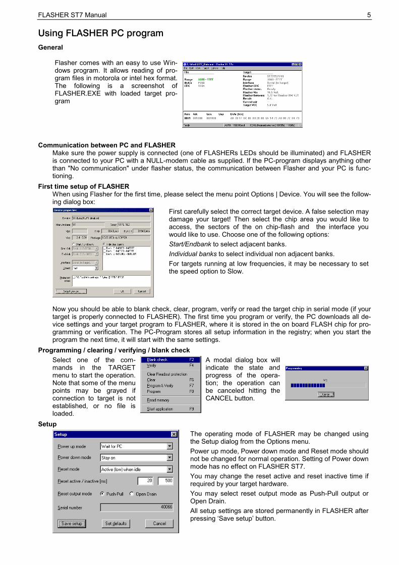
Flasher comes with an easy to use Win-dows program. It allows reading of pro-gram files in motorola or intel hex format. The following is a screenshot of FLASHER.EXE with loaded target pro-gram
Communication between PC and FLASHER Make sure the power supply is connected (one of FLASHERs LEDs should be illuminated) and FLASHER is connected to your PC with a NULL-modem cable as supplied. If the PC-program displays anything other than "No communication" under flasher status, the communication between Flasher and your PC is func-tioning.
First time setup of FLASHER When using Flasher for the first time, please select the menu point Options | Device. You will see the follow-ing dialog box:
First carefully select the correct target device. A false selection may damage your target! Then select the chip area you would like to access, the sectors of the on chip-flash and the interface you would like to use. Choose one of the following options: Start/Endbank to select adjacent banks. Individual banks to select individual non adjacent banks. For targets running at low frequencies, it may be necessary to set the speed option to Slow.
Now you should be able to blank check, clear, program, verify or read the target chip in serial mode (if your target is properly connected to FLASHER). The first time you program or verify, the PC downloads all de-vice settings and your target program to FLASHER, where it is stored in the on board FLASH chip for pro-gramming or verification. The PC-Program stores all setup information in the registry; when you start the program the next time, it will start with the same settings.
Programming / clearing / verifying / blank check Select one of the com-mands in the TARGET menu to start the operation. Note that some of the menu points may be grayed if connection to target is not established, or no file is loaded.
A modal dialog box will indicate the state and progress of the opera-tion; the operation can be canceled hitting the CANCEL button.
Setup
The operating mode of FLASHER may be changed using the Setup dialog from the Options menu. Power up mode, Power down mode and Reset mode should not be changed for normal operation. Setting of Power down mode has no effect on FLASHER ST7. You may change the reset active and reset inactive time if required by your target hardware. You may select reset output mode as Push-Pull output or Open Drain. All setup settings are stored permanently in FLASHER after pressing �Save setup� button.
FLASHER ST7 Manual 6
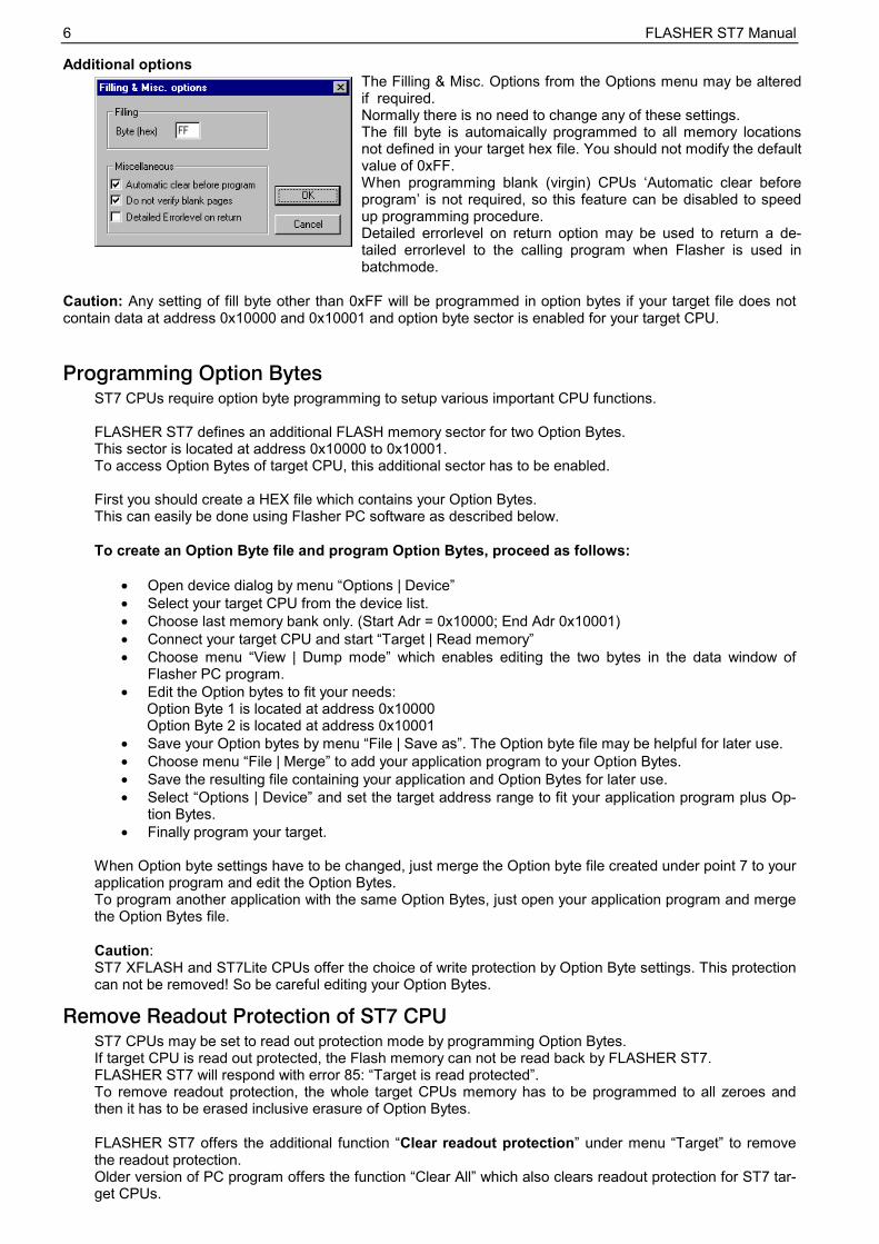
Additional options
The Filling & Misc. Options from the Options menu may be altered if required. Normally there is no need to change any of these settings. The fill byte is automaically programmed to all memory locations not defined in your target hex file. You should not modify the default value of 0xFF. When programming blank (virgin) CPUs �Automatic clear before program� is not required, so this feature can be disabled to speed up programming procedure. Detailed errorlevel on return option may be used to return a de-tailed errorlevel to the calling program when Flasher is used in batchmode.
Caution: Any setting of fill byte other than 0xFF will be programmed in option bytes if your target file does not contain data at address 0x10000 and 0x10001 and option byte sector is enabled for your target CPU.
Programming Option Bytes ST7 CPUs require option byte programming to setup various important CPU functions. FLASHER ST7 defines an additional FLASH memory sector for two Option Bytes. This sector is located at address 0x10000 to 0x10001. To access Option Bytes of target CPU, this additional sector has to be enabled. First you should create a HEX file which contains your Option Bytes. This can easily be done using Flasher PC software as described below. To create an Option Byte file and program Option Bytes, proceed as follows:
• Open device dialog by menu �Options | Device� • Select your target CPU from the device list. • Choose last memory bank only. (Start Adr = 0x10000; End Adr 0x10001) • Connect your target CPU and start �Target | Read memory� • Choose menu �View | Dump mode� which enables editing the two bytes in the data window of
Flasher PC program. • Edit the Option bytes to fit your needs:
Option Byte 1 is located at address 0x10000 Option Byte 2 is located at address 0x10001
• Save your Option bytes by menu �File | Save as�. The Option byte file may be helpful for later use. • Choose menu �File | Merge� to add your application program to your Option Bytes. • Save the resulting file containing your application and Option Bytes for later use. • Select �Options | Device� and set the target address range to fit your application program plus Op-
tion Bytes. • Finally program your target.
When Option byte settings have to be changed, just merge the Option byte file created under point 7 to your application program and edit the Option Bytes. To program another application with the same Option Bytes, just open your application program and merge the Option Bytes file. Caution: ST7 XFLASH and ST7Lite CPUs offer the choice of write protection by Option Byte settings. This protection can not be removed! So be careful editing your Option Bytes.
Remove Readout Protection of ST7 CPU ST7 CPUs may be set to read out protection mode by programming Option Bytes. If target CPU is read out protected, the Flash memory can not be read back by FLASHER ST7. FLASHER ST7 will respond with error 85: �Target is read protected�. To remove readout protection, the whole target CPUs memory has to be programmed to all zeroes and then it has to be erased inclusive erasure of Option Bytes. FLASHER ST7 offers the additional function �Clear readout protection� under menu �Target� to remove the readout protection. Older version of PC program offers the function �Clear All� which also clears readout protection for ST7 tar-get CPUs.
FLASHER ST7 Manual 7
Clock options of ST7 CPU ST7 CPUs require CPU clock to enter ICC mode after reset. There are two different ways to invoke ICC communication: • Enter ICC mode and do not take into account option byte settings. (OPT disabled) This mode always requires external clock supplied to target CPU. The clock might be supplied by any external oscillator (not crystal or resonator). Flasher delivers approximately 11 MHz clock at OSC_CLK (pin 9) which has to be connected to the clock input of target CPU, if external oscillator is not available on target board. • Enter ICC mode and take into account option byte settings. (OPT enabled) This mode activates CPUs internal oscillator, if option bytes are set up to activate internal oscillator. Connection of OSC_CLK is not required in this case and Flasher will not deliver any clock signal on pin 9. To select between the two different modes, you have to select the correct device from menu Device. The device names in the list are followed by �OPT disabled� to enter ICC mode without option byte settings (1.) �OPT enabled� to enter ICC mode and take into account option byte settings (2.) Special consideration for ST7Lite2 CPUs: External clock has to be connected to PB4 in case virgin CPUs should be programmed and �OPT disabled� is used as ICC entry mode.
Using the serial link to program in circuit
FLASHER can be used for in circuit programming of ST7 CPUs, which incorporate built in firmware for serial update of user flash. The target system has to be designed to support this mode of opera-tion. Refer to target specific connection diagrams or Users manuals of your target CPU.
FLASHERTarget system
withFLASH MCU
Clocksynchrounous
serialRS232
StandardNul-Modem
cable
Customercable
Basic configuration for serial programming
Serial programming, technical details Serial programming of ST7 microcontrollers uses ICC protocol. The commands which are used are de-scribed in the ST manual. In general, the sequence is as follows: • Flasher resets the target CPU and then sets up the target to enter ICC mode • Flasher downloads an application program (RAMCODE) to target CPU • Flasher starts the target RAMCODE • RAMCODE accepts commands from Flasher to read, clear or program the target CPU.
Operating FLASHER in stand-alone mode
After download, the target program and all settings are stored in FLASHERs on board FLASH memory. Any number of microcontrollers may be now programmed by FLASHER (one at a time) without the need of a host PC, by simply pressing the start button. FLASHER will use the settings which have been made in the PC-program. This includes the selection of target address range as well as any options. Whether the target CPU will be erased before programming depends on setting of option �Automatic clear before program�. Progress and result of the operation is indicated by the LED: Status of LED Meaning GREEN, flashing Erasing / Programming / Verifying operation in progress GREEN Programming operation successful RED Programming operation failed
Remote control of FLASHER ST7 FLASHER ST7 can be remote controlled by automated testers without the need of a connection to PC and Flashers PC program. Therefore FLASHER ST7 is equipped with additional hardware control functions, which are connected to the SUBD9 male connector, normally used as RS232 interface to PC. The following table shows the pin functions of remote control circuitry of FLASHER:
FLASHER ST7 Manual 8 Pin No. Function Description 1 START A positive pulse of any voltage between 5 and 30V with duration of min. 30 ms starts
�Auto� function (Clear / Program / Verify) on falling edge of pulse. Whether Clear is executed depends on Options | Filling & misc. | Automatic clear before program.
4 BUSY As soon as Auto-Function is started, BUSY becomes active, which means that tran-sistor is switched OFF.
7 OK This output reflects result of last action. It is valid after BUSY turned back to passive state. The output transistor is switched ON to reflect OK state.
5 GND Common Signal ground Shown below is a timing chart of remote control function:
The following diagram shows the internal remote control circuitry of FLASHER ST7:
Target system interface for ST7 Target interface pin description
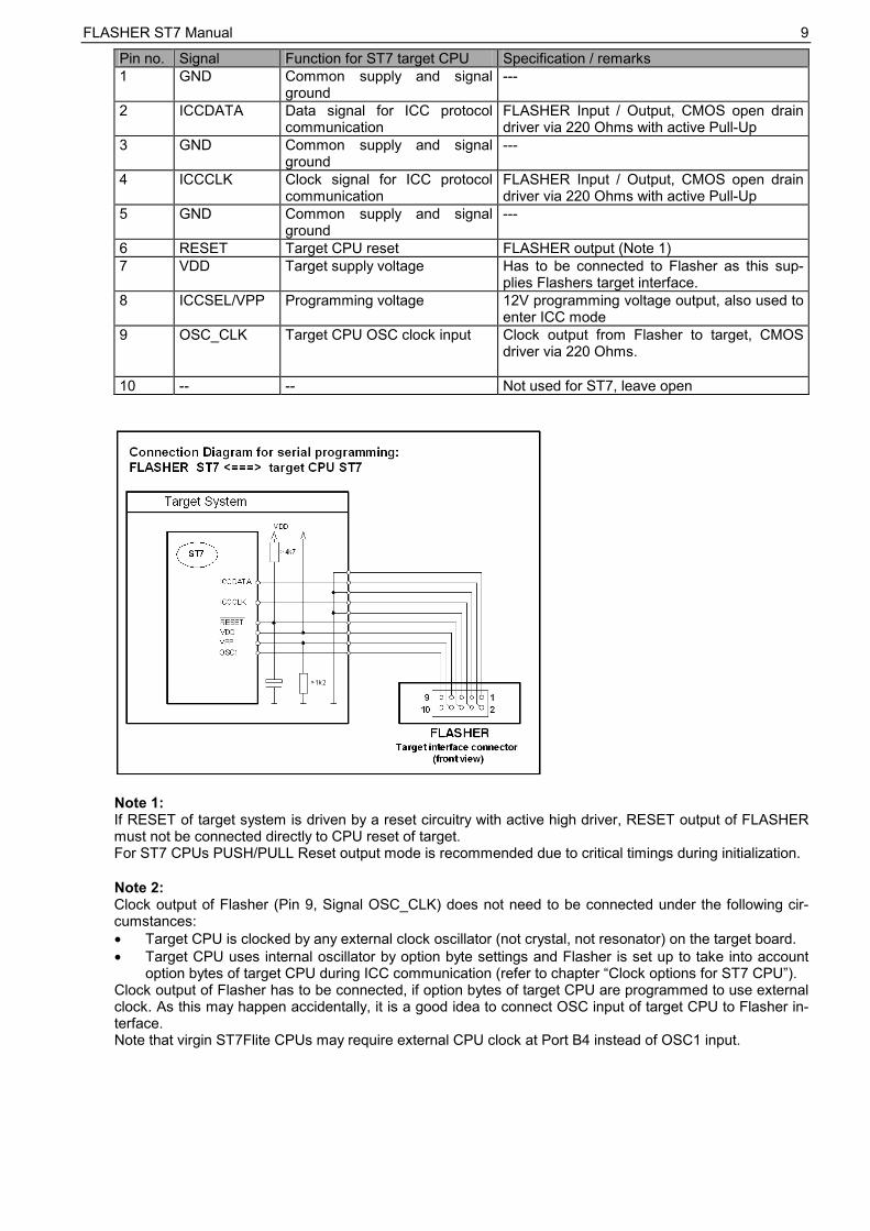
The ICC interface from Flasher to target system is realized by a 10 pin dual in line pin connector,(pin1 is marked at the connector) at the front of FLASHER. Flasher for ST7 uses the standard interface cable connection as described in ST 7 data sheets.
FLASHER ST7 Manual 9
Pin no. Signal Function for ST7 target CPU Specification / remarks 1 GND Common supply and signal
ground ---
2 ICCDATA Data signal for ICC protocol communication
FLASHER Input / Output, CMOS open drain driver via 220 Ohms with active Pull-Up
3 GND Common supply and signal ground
---
4 ICCCLK Clock signal for ICC protocol communication
FLASHER Input / Output, CMOS open drain driver via 220 Ohms with active Pull-Up
5 GND Common supply and signal ground
---
6 RESET Target CPU reset FLASHER output (Note 1) 7 VDD Target supply voltage Has to be connected to Flasher as this sup-
plies Flashers target interface. 8 ICCSEL/VPP Programming voltage 12V programming voltage output, also used to
enter ICC mode 9 OSC_CLK Target CPU OSC clock input Clock output from Flasher to target, CMOS
driver via 220 Ohms.
10 -- -- Not used for ST7, leave open
Note 1: If RESET of target system is driven by a reset circuitry with active high driver, RESET output of FLASHER must not be connected directly to CPU reset of target. For ST7 CPUs PUSH/PULL Reset output mode is recommended due to critical timings during initialization. Note 2: Clock output of Flasher (Pin 9, Signal OSC_CLK) does not need to be connected under the following cir-cumstances: • Target CPU is clocked by any external clock oscillator (not crystal, not resonator) on the target board. • Target CPU uses internal oscillator by option byte settings and Flasher is set up to take into account
option bytes of target CPU during ICC communication (refer to chapter �Clock options for ST7 CPU�). Clock output of Flasher has to be connected, if option bytes of target CPU are programmed to use external clock. As this may happen accidentally, it is a good idea to connect OSC input of target CPU to Flasher in-terface. Note that virgin ST7Flite CPUs may require external CPU clock at Port B4 instead of OSC1 input.
FLASHER ST7 Manual 10
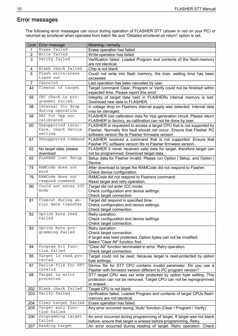
Error messages
The following error messages can occur during operation of FLASHER ST7 (shown in red on your PC) or returned as errorlevel when operated from batch file and �Detailed errorlevel on return� option is set. Code Error message Meaning / remedy
1 Erase failed Erase operation has failed 2 Write failed Write operation has failed 3 Verify failed Verification failed. Loaded Program and contents of the flash-memory
are not identical. 4 Blank check failed Chip is not blank 5 Flash write/erase
timed outCould not write into flash memory, the max. waiting time has been exceeded
7 Canceled Last operation has been canceled by user. 43 Timeout of target Target command Clear, Program or Verify could not be finished within
expected time. Please report this error. 55 CRC check in pro-
grammer failed.Integrity of target data held in FLASHERs internal memory is lost. Download new data to FLASHER.
56 Internal Vcc dropduring operation
A voltage drop on Flashers internal supply was detected. Internal data may be damaged.
58 DAC for Vpp notcalibrated
FLASHER lost calibration data for Vpp generation circuit. Please return FLASHER to factory, as calibration can not be done by user.
60 Unsupported inter-face, check devicesetting
FLASHER is requested to access a target CPU that is not supported by Flasher. Normally this fault should not occur. Ensure that Flasher PC software version fits to Flasher firmware version
61 Unsupported command FLASHER received a command that is not supported. Ensure that Flasher PC software version fits to Flasher firmware version.
62 No target data, please download
FLASHER 5 never received valid data for target, therefore target can not be programmed. Download target data.
63 FLASHER lost Setup Setup data for Flasher invalid. Please run Option | Setup. and Option | Device.
75 RAMCode does notwork
After download to target the RAMCode did not respond to Flasher. Check device configuration.
76 RAMCode does notrespond command
RAMCode did not respond to Flashers command. Reset target and retry operation.
80 Could not enter ICCmode
Target did not enter ICC mode. Check configuration and device settings. Check target connection.
81 Timeout during se-rial data transfer
Target did respond in specified time. Check configuration and device settings. Check target connection.
82 Option byte readfailed
Retry operation. Check configuration and device settings. Check target connection.
83 Option byte pro-gramming failed
Retry operation. Check target connection. If target was read protected, Option bytes can not be modified. Select "Clear All" function first.
84 Program All func-tion failed
"Clear All" function terminated in error. Retry operation. Check target connection.
85 Target is read pro-tected
Target could not be read, because target is read-protected by option byte settings.
87 Device file for ST7invalid
Device file for ST7 CPU contains invalid parameter. Do you use a Flasher with firmware version different to PC program version?
88 Target is writeprotected
ST7 target CPU was set write protected by option byte setting. This protection can not be removed. Target CPU can not be reprogrammed or erased.
202 Blank check failed Target CPU is not blank. 203 Verify failed Verification failed. Loaded Program and contents of target CPUs flash-
memory are not identical. 204 Clear target failed Erase operation has failed. 205 Target auto func-
tion failedAny error occurred during �Auto� function (Clear / Program / Verify)
206 Programming targetfailed
An error occurred during programming of target. If target was not blank before, ensure that target is erased before programming. Retry.
207 Reading target An error occurred during reading of target. Retry operation. Check
FLASHER ST7 Manual 11failed connection to target.
210 Could not opensource file
The source file given as parameter could not be opened. Check file name or path.
count.Check parameter. Refer to command description.
213 Invalid commandsyntax.
Check parameter. Refer to command description.
214 Firmware mismatch PC software version differs from firmware version of Flasher. Download new firmware via Options menu. Otherwise proper function can not be guaranteed.
215 The selected targetchip is not sup-ported by the con-nected programmer.
Check and setup device settings.
216 Session mismatch.Resetting connec-tion
It seemed, that Flasher was disconnected during communication be-tween Flasher and PC. Try an other COM port.
217 Flasher refusesconnection..
Did you select a chip which is not supported ? Check device settings.
218 None of the se-lected com ports isavailable.
PC program could not open selected COM-Port. Select an other COM port.
219 Error in HEX file The HEX file for target could not be read. Check file format. 220 Invalid file exten-
sion, use .MOT,.HEX or .BIN
You tried to open or save a Hex file with unsupported file extension.
221 Invalid file name You tried to Open or merge a file that could not be found. Check file name or path.
Supply voltage of target exceeds max value defined for selected de-vice. Check device settings, connection to Flasher and target supply. If everything is correct, Flashers voltage measurement circuitry seems to be damaged and has to be repaired.
224 VCCS < VCCSmin(Target supplyvoltage too low...)
Supply voltage of target is lower than min value defined for selected device. Check device settings, connection to Flasher and target supply. If everything is correct, Flashers voltage measurement circuitry seems to be damaged and has to be repaired.
225 Flasher Input volt-age too low
Flashers supply voltage is lower than required to generate program-ming voltage of connected target CPU. Check supply voltage.
226 Assertion PC program internal error. Restart and try again. 227 Invalid default
program settingsfound. Please setupdevice.
Your registry contained invalid data about Flasher PC program. Setup device and other options.
228 Flasher not ready ! Setup data could not be sent to Flasher. Is a Flasher connected to your PC? Check COM port.
229 Invalid commandlineoption
Your command line parameter contains a command which is not sup-ported.
230 Flasher defect !!!Target interfacedoes not work.
Target interface of FLASHER not found during initialization. Flasher has to be repaired.
FLASHER ST7 Manual 12
Trouble shooting Proper operation of FLASHER ST7 depends on your target system. If you have any trouble operating FLASHER ST7, please: a) Check your target hardware, b) Check the connecting cable, c) Use an oscilloscope to check the state of all signals on the target connector, especially to check if the
target CPU is RESET properly and Programming voltage output, OSC_CLK, ICCDATA and ICCCLK signals work properly,
d) Make sure FLASHER firmware version matches the PC software version, if not choose Menu | Options | Download Firmware.
Support For support questions, please consult our website at www.segger.com. If this does not answer your ques-tions, please send an email to [email protected].
FLASHER ST7 Manual 13
Using Flasher in batch mode
Introduction Flasher.exe supports command line options to enable automated programming of targets. This document describes the supported commands and their respective parameters. Flasher PC software version 1.72b or above replaces FlasherPro, which is not delivered anymore.
How to start Flasher program in batch mode To use Flasher in batch mode, just call Flasher.exe directly from DOS-Box or start any batch file which calls Flasher.exe, To start any action, parameter may be passed as command line options.
General rules • The first parameter specified must be the file to load, if download is required. • The return code is 0 if all operations have been executed successfully, !=0 otherwise. • All commands are identical to the corresponding commands in the menu bar. • All commands are processed from left to right. • If �-exit� is specified as the last command, the program will terminate as soon as any error occurs or af-
ter all commands have been executed. • If one parameter contains a space use quotation marks for this parameter.
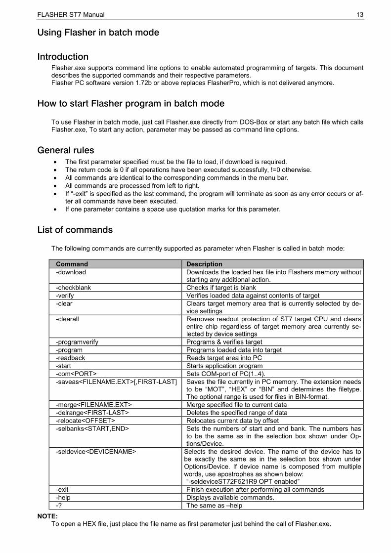
List of commands
The following commands are currently supported as parameter when Flasher is called in batch mode:
Command Description -download Downloads the loaded hex file into Flashers memory without
starting any additional action. -checkblank Checks if target is blank -verify Verifies loaded data against contents of target -clear Clears target memory area that is currently selected by de-
vice settings -clearall Removes readout protection of ST7 target CPU and clears
entire chip regardless of target memory area currently se-lected by device settings
-programverify Programs & verifies target -program Programs loaded data into target -readback Reads target area into PC -start Starts application program -com<PORT> Sets COM-port of PC(1..4). -saveas<FILENAME.EXT>[,FIRST-LAST] Saves the file currently in PC memory. The extension needs
to be �MOT�, �HEX� or �BIN� and determines the filetype. The optional range is used for files in BIN-format.
-merge<FILENAME.EXT> Merge specified file to current data -delrange<FIRST-LAST> Deletes the specified range of data -relocate<OFFSET> Relocates current data by offset -selbanks<START,END> Sets the numbers of start and end bank. The numbers has
to be the same as in the selection box shown under Op-tions/Device.
-seldevice<DEVICENAME> Selects the desired device. The name of the device has to be exactly the same as in the selection box shown under Options/Device. If device name is composed from multiple words, use apostrophes as shown below: �-seldeviceST72F521R9 OPT enabled�
-exit Finish execution after performing all commands -help Displays available commands. -? The same as �help
NOTE: To open a HEX file, just place the file name as first parameter just behind the call of Flasher.exe.
FLASHER ST7 Manual 14
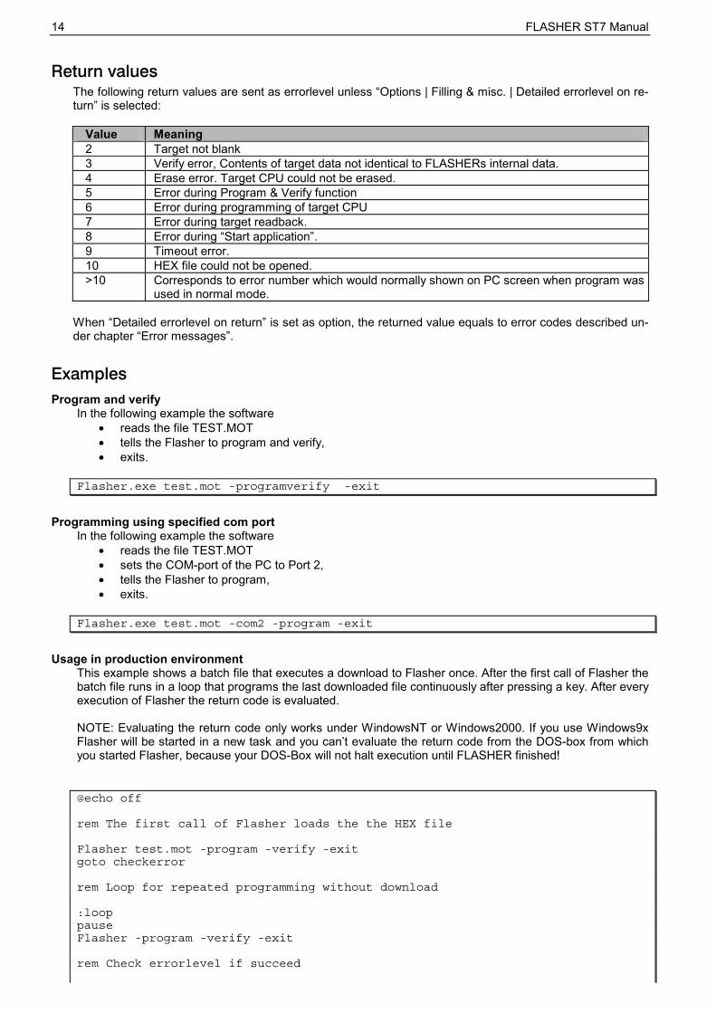
Return values The following return values are sent as errorlevel unless �Options | Filling & misc. | Detailed errorlevel on re-turn� is selected:
Value Meaning 2 Target not blank 3 Verify error, Contents of target data not identical to FLASHERs internal data. 4 Erase error. Target CPU could not be erased. 5 Error during Program & Verify function 6 Error during programming of target CPU 7 Error during target readback. 8 Error during �Start application�. 9 Timeout error. 10 HEX file could not be opened. >10 Corresponds to error number which would normally shown on PC screen when program was
used in normal mode. When �Detailed errorlevel on return� is set as option, the returned value equals to error codes described un-der chapter �Error messages�.
Examples Program and verify
In the following example the software • reads the file TEST.MOT • tells the Flasher to program and verify, • exits.
Flasher.exe test.mot -programverify -exit
Programming using specified com port
In the following example the software • reads the file TEST.MOT • sets the COM-port of the PC to Port 2, • tells the Flasher to program, • exits.
Flasher.exe test.mot -com2 -program -exit
Usage in production environment
This example shows a batch file that executes a download to Flasher once. After the first call of Flasher the batch file runs in a loop that programs the last downloaded file continuously after pressing a key. After every execution of Flasher the return code is evaluated. NOTE: Evaluating the return code only works under WindowsNT or Windows2000. If you use Windows9x Flasher will be started in a new task and you can�t evaluate the return code from the DOS-box from which you started Flasher, because your DOS-Box will not halt execution until FLASHER finished! @echo off
rem The first call of Flasher loads the the HEX file
The following example shows a batch file, where the software • reads file A.HEX, • deletes the range 0xC000..0xFFFF, • moves the remaining bytes 0x4000 bytes up, • saves the memory contents as B.MOT, • reads the file A.HEX again, • deletes the range 0x1000..0xBFFF, • moves the remaining bytes 0xB000 bytes down, • saves the memory contents as C.MOT, • merges the files B.MOT and C.MOT • and save the new file as RESULT.BIN.