16
Valve Actuators Type PA58 Multi-Spring Pneumatic Actuator RCV-UM-01770-EN-01 (October 2015) User Manual

Valve ActuatorsType PA58 Multi-Spring Pneumatic Actuator
RCV-UM-01770-EN-01 (October 2015) User Manual

CONTENTS
Description 3
Unpacking & Inspection 3
Storage 3
Actuator Lifting Instructions 4
Identification Label 4
Before Operating the Actuator 5
Installation 5
After Commissioning the Actuator 5
Safety 6
Specifications 7
Materials 7
Action 7
Maintenance 8
General 8
Torque Settings 8
Before and After Maintenance 8
Maintenance Schedule 8
Important Notes 8
Disassembling the Actuator 9
Assembling the Actuator 12
Troubleshooting 14
Personal Protection Equipment 14
Scrapping Soft Parts 14
Emergency Situations 14
Reversing The Actuator Action 14
Converting a Normally Closed Actuator to a Normally Open Actuator 14
Converting a Normally Open Actuator to a Normally Closed Actuator 14
Parts Drawings 15
Valve Actuators, Type PA58 Multi-Spring Pneumatic Actuator
Page ii October 2015RCV-UM-01770-EN-01

DESCRIPTIONThe PA58 actuator is a 58 square-inch pneumatic, multi-spring diaphragm actuator designed specifically to fit the RCV product line The actuator can be used with a wide range of valve solutions from larger process valves to high pressure applications The actuator is field reversible (without additional parts) allowing flexibility within the field This actuator is available air-to-open or air-to-close The yoke and the actuator housings are made of carbon steel and coated with epoxy for corrosion resistance
Unpacking & InspectionUpon opening the shipping container, visually inspect the product and applicable accessories for any physical damage such as scratches, loose or broken parts, or any other sign of damage that may have occurred during shipment
NOTE:N If damage is found, request an inspection by the carrier’s agent within 48 hours of delivery and file a claim with the carrier A claim for equipment damage in transit is the sole responsibility of the purchaser
• Check the contents of the box against the packing slip
• Do not lift box/heavy products manually Manual lifting of actuators may cause serious injury
• For heavy actuators, follow the lifting procedure in "Actuator Lifting Instructions" on page 4
• Keep the box on flat/plain surface with arrow facing up
• Open the box from top only
• Handle the product with care
StorageThe Type PA58 actuators are factory lubricated for 10,000 cycles under normal operating conditions The ports are plugged to prevent foreign particles from entering during shipping If the actuators are not for immediate use, take the following precautions during storage
• Store the product with care
• Protect the product from rain and heat
• Do not remove the plastic plugs on the air supply ports until the actuator is in use
• Store the actuator with its bottom resting on flat base
• Duration of storage: 2 years maximum from date of manufacture
Figure 1: Actuator in upright position
Description
Page 3 October 2015 RCV-UM-01770-EN-01

Actuator Lifting Instructions
Required Materials
Use a polyester sling with the following specifications to lift the actuator:• Material: Polyester
• Maximum working load that sling can lift: 800 kg
• Factor of safety considered: 8
• Length of the sling: 1 5 m
• Width of the sling: 25 mm minimum
Figure 2: Lifting the actuator
Lifting Procedure
1 Use hook and sling at both the ends of the actuator 2 Put the sling into the hook of the crane 3 Verify that both the ends of the sling are properly hooked into the lifting bolts 4 Lift the actuator slowly with the help of crane at an appropriate height of 500 mm 5 Adjust the sling, if necessary, so the actuator is properly balanced 6 Lift the actuator to the required height 7 Rest the actuator on the surface 8 Release the tension on the sling and remove the sling
Identification LabelAn identification label is attached to each actuator cover When ordering parts, requesting information or service assistance, provide all of the label information
Figure 3: Product label
Description
Page 4 October 2015RCV-UM-01770-EN-01

Before Operating the Actuator
• Inspect the actuator for any damage
• Make sure all the connections have been made properly
• Make sure the specified air pressure is in the line and that the air is dry filtered, instrumentation grade air
• No shop air should be used at any time Any moisture in air supply will seriously damage the actuator or valve positioner (if installed)
InstallationNOTE:N Use 1/4 in NPT fittings for connection Pipe connections to be made should be rigid or flexible, according to the
requirements of the user
MAKE SURE THAT CONNECTIONS MADE (EITHER FLEXIBLE OR RIGID) MUST BE INTENDED FOR THEIR USE IN POTENTIALLY EXPLOSIVE ENVIRONMENT.
THE MAXIMUM OPERATING PRESSURE IS 65 PSIG.
After Commissioning the Actuator
• The actuator should let the valve open and close smoothly with no jerking or uneven motion
• There should be no leakage of air from the actuator
• There should be no abnormal noise from the actuator If you find any issue with the functioning of the actuator, see "Troubleshooting" on page 14 If troubleshooting does not rectify the issue, contact Technical Service department
Description
Page 5 October 2015 RCV-UM-01770-EN-01

SAFETYThe installation of the PA58 actuator must comply with all applicable federal, state, and local rules, regulations, and codes Failure to read and follow these instructions can lead to misapplication or misuse of the product, resulting in personal injury and damage to equipment
• Read and save all instructions prior to installing, operating and servicing this product
• Follow all warnings, cautions and instructions marked on, and supplied with, the product
• Inform and educate personnel in the proper installation, operation and maintenance of the product
• Install equipment as specified in the installation instructions and per applicable local and national codes Connect all products to the proper electrical sources
• For proper performance, use qualified personnel to install, operate, update, tune and maintain the product
• When replacement parts are required, ensure that the qualified service technician uses factory replacement parts Substitutions may result in fire, electrical shock, other hazards, or improper equipment operation
• Keep all product protective covers in place (except when installing, or when maintenance is being performed by qualified personnel) to prevent electrical shock, personal injury or damage to the actuator
Safety
Page 6 October 2015RCV-UM-01770-EN-01

SPECIFICATIONSActuator Type Multi-spring diaphragm linear pneumatic actuatorEffective Diaphragm Area 58 in 2 (225 sq cm)Stroke 1 in (Smaller stroke available with positioner)Operating Medium Filtered dry instrument grade air supply or dry nitrogenSpring (Bench) Loading Adjustable (select ranges available)Action ATO or ATC (reversible without additional parts)Accessory Mounting IEC534 (Namur)Operating Pressure Max. 65 psig @ 70° F (4 5 bar @ 21° C)Diaphragm Pressure Max. 90 psig @ 70° F (6 2 bar @ 21° C)Upper Ambient Temperature Limit 176° F (80° C) @ 30 psigLower Ambient Temperature Limit –20° F (–29° C) @ 30 psigMax. Surface Temperature 120° F (49° C) at 116 lb and room temperature or ambient temperature of 86° F (30° C)Signal Range Standard 3…27 psig (Others available)Max. Noise Level 70 dB maximum measured on pressure level scale for the actuator (intermittent)Weight 35 lb (16 kg)
Table 1: Product specifications
MaterialsTop Cover ASTM A620/IS 513Bottom Cover ASTM A620/IS 513Working Diaphragm Neoprene with nylon fabricYoke C S ASTM A216 Gr WCBSpindle S S AISI 304Working Diaphragm Holder IS 2062 MSBalancing Plate ASTM A620/IS 513Main Spring Chrome VanadiumBellow NitrileRod Wiper Seal NitrileO-Ring Nitrile
Table 2: Material specifications
ACTION
• Air-to-Open (Fail Close Condition, Normally Closed): Actuator air supply to be connected to Port B Port A to be used as exhaust port
• Air-to-Close (Fail Open Condition, Normally Open): Actuator air supply to be connected to Port A Port B to be used as exhaust port
SpringsPort A
Air Supply
Port B
DiaphragmSprings
Port A
Air Supply
Port B
Diaphragm
Figure 4: ATO, NC Figure 5: ATC, NO
Specifications
Page 7 October 2015 RCV-UM-01770-EN-01

MAINTENANCE
GeneralType PA58 actuators are supplied with metric/UNC fasteners Under normal operating conditions, the actuator requires only periodic observation for proper adjustment Service kits are available to replace seals and diaphragm
Torque Settings
Size Top Cover Bolts Tightening Torques (N-m)
M4 5M5 / 10"-24 UNC 10
M6 / 1/4"- 20 UNC 16M8 / 5/16"-18 UNC 40M10 / 3/8"- 16 UNC 80M12 / 1/2" - 13 UNC 135M16 / 5/8" - 11 UNC 360
Table 1: Torque settings
Before and After Maintenance
• Verify that all internal ports are clean and free from foreign particles
• Verify that all the soft parts are clean and free from dust
• Verify that all the components are assembled correctly
• Verify the cleanliness of inside grease before assembly
• Verify that all the parts are properly fitted
• Verify that the top and bottom cover bolts are tightened to the required tightening torques, per Table 1
• After introducing air in the actuator, check for air leakage with soap water bubble
Maintenance Schedule
• Perform periodic maintenance of the actuator after every 10,000 cycles
• Replace sealing parts of the actuator (like O-rings) after 10,000 cycles
Important Notes
• The inside temperature (function temperature) of the actuator may rise to the maximum 176° F (80° C) under extreme working conditions
• Design the control system so the actuator operates only after it is supplied with air
• The actuator START/STOP function depends only upon the supply of air The user controls the air supply
• Air to be supplied for actuator must be clean and dry and should not contain any hazardous gas
• In case of accidental blockage, do not open the actuator Return the actuator to the factory for further maintenance
• Use a silencer at the exhaust port
Maintenance
Page 8 October 2015RCV-UM-01770-EN-01

Disassembling the Actuator
IMPORTANT Before disassembling the actuator, turn off the air supply and remove the air connection.
36
24
23
2221
8
9
5253
4
217
1918
14
13111210
1
76
162015
2728
26
34313227
3330
2829
26
9
36
24
2322
21
1 YOKE2 HEX LOCKNUT
HEX LOCKNUT
3456789
10
26252423222120191817161514131211
MAIN SPRINGANTI ROTATION ROD
BALANCING PLATEWORKING DIAPHRAGMWORKING DIAPHRAGM HOLDERBOTTOM COVERNIPPLE NUTFERRULEELBOWHEX HD BOLTGASKET + PLAIN WASHERDURO BUSHO-RINGROD SEALBUSH BOTTOM COVERROD WIPER SEALSPINDLEBELLOWPAN HD SCREWSTROKE PLATE
81
1111
11111111
1
11
11
1
1
1
11
44+4
2
SR.SR. DESCRIPTIONDESCRIPTION QTY.QTY. SPARESPARE
36343332
30292827
31
STROKE LIMITERBREATHERLIFTING BOLTHEX LOCKNUTHEX NUTPLAIN WASHER
HEX BOLTHEX BOLT
TOP COVER
1
1
2
4
48
24
6
Components in spare kit.
NOTE: Observe min. and max. pressure conditions.
Assembly Sequencefor Normally Closed (Air-to-Open)
Assembly Sequencefor Normally Open (Air-to-Close)
HEX LOCKNET (LH)INDICATORCOUPLER
Figure 6: Assembly sequences
Maintenance
Page 9 October 2015 RCV-UM-01770-EN-01

Air-to-Open (Fail Safe Close Condition, Normally Closed)
1 Shut off the air supply to the actuator 2 Disconnect the air piping from the bottom cover (20)
AT THIS TIME PROVISIONS MUST BE MADE TO SUPPORT AND LIFT THE ACTUATOR OFF THE BODY USING RECOMMENDED LIFT SUPPORTS AND PROCEDURES.
3 Remove the anti-rotation rod (25) by turning it counterclockwise 4 Disassemble the coupler (03) by turning it counterclockwise to disengage it from the spindle (09) 5 Remove the bellow (08) and the left-hand threaded hexagonal locknut(05) 6 To remove the top cover (27) from the actuator:
a Remove the lifting bolts (33) b Rotate counterclockwise the long, full-threaded hexagonal bolts (29), the nuts (32) and washers (30) c Disassemble the other hexagonal bolts (28), nuts (31) and washers (30) and remove top cover (27)
TOP COVER (27) IS UNDER SPRING TENSION AND IS EQUIPPED WITH TENSION BOLTS (29) WHICH MUST BE REMOVED LAST.
7 Remove the springs (26) from the balancing plate (23) 8 To disassemble the diaphragm:
a Remove the spindle (09) from the diaphragm holder (21) b Remove the balancing plate (23) and working diaphragm (22) by unscrewing the stroke limiter (36) and locknut (24)
9 Remove the hexagonal bolts (16), gasket and washers (15) to disassemble the bottom cover (20) from the yoke (01) 10 Remove the O-ring (13), bush bottom cover (11), rod seal (12) and rod wiper seal (10) from the yoke (01)
Do not remove the duro bush (14) from bush bottom cover (11).11 Remove the stroke plate (06) to complete the disassembly of the actuator
Maintenance
Page 10 October 2015RCV-UM-01770-EN-01
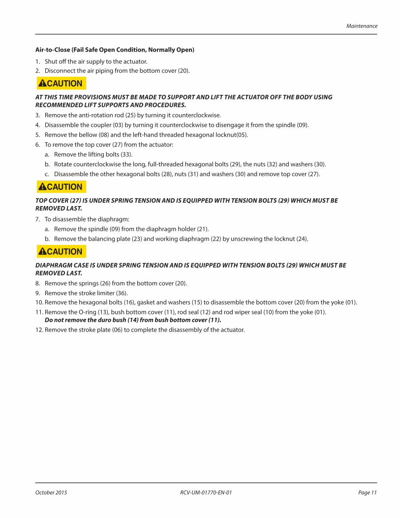
Air-to-Close (Fail Safe Open Condition, Normally Open)
1 Shut off the air supply to the actuator 2 Disconnect the air piping from the bottom cover (20)
AT THIS TIME PROVISIONS MUST BE MADE TO SUPPORT AND LIFT THE ACTUATOR OFF THE BODY USING RECOMMENDED LIFT SUPPORTS AND PROCEDURES.
3 Remove the anti-rotation rod (25) by turning it counterclockwise 4 Disassemble the coupler (03) by turning it counterclockwise to disengage it from the spindle (09) 5 Remove the bellow (08) and the left-hand threaded hexagonal locknut(05) 6 To remove the top cover (27) from the actuator:
a Remove the lifting bolts (33) b Rotate counterclockwise the long, full-threaded hexagonal bolts (29), the nuts (32) and washers (30) c Disassemble the other hexagonal bolts (28), nuts (31) and washers (30) and remove top cover (27)
TOP COVER (27) IS UNDER SPRING TENSION AND IS EQUIPPED WITH TENSION BOLTS (29) WHICH MUST BE REMOVED LAST.
7 To disassemble the diaphragm:a Remove the spindle (09) from the diaphragm holder (21) b Remove the balancing plate (23) and working diaphragm (22) by unscrewing the locknut (24)
DIAPHRAGM CASE IS UNDER SPRING TENSION AND IS EQUIPPED WITH TENSION BOLTS (29) WHICH MUST BE REMOVED LAST.
8 Remove the springs (26) from the bottom cover (20) 9 Remove the stroke limiter (36) 10 Remove the hexagonal bolts (16), gasket and washers (15) to disassemble the bottom cover (20) from the yoke (01) 11 Remove the O-ring (13), bush bottom cover (11), rod seal (12) and rod wiper seal (10) from the yoke (01)
Do not remove the duro bush (14) from bush bottom cover (11).12 Remove the stroke plate (06) to complete the disassembly of the actuator
Maintenance
Page 11 October 2015 RCV-UM-01770-EN-01

Assembling the Actuator
Air-to-Open (Fail Safe Close Condition, Normally Closed)
• Install the actuators in a position that allows full access for actuator maintenance purposes
• The actuator ambient temperature limits are –10…80° C
• For low temperature conditions, the air supply must be dry
• For high temperature conditions, insulate the control valve and pipework to protect the actuator 1 Make sure all parts are deburred, clean and lubricated 2 Fit these items, in order, into the yoke (01):
a Yoke assemblyb Rod wiper seal (10)c Rod seal (12)d Bush bottom cover (11)e Duro bush (14)f O-ring (13)
3 Fill the yoke (01) and bottom cover (20) with Lock-Tite 574 sealer so they are fully air-tight 4 Attach the bottom cover (20) to the yoke (01) with hexagonal bolts (16) and washers (15) 5 Clean the diaphragm holder (21) and fill the groove with 574 lock-tite sealer 6 Attach the diaphragm holder (21) to the working diaphragm (22) and the balancing plate (23) with the hexagonal
locknut (24) Tighten the locknut 7 Fit the spindle (09) into the diaphragm holder (21) as shown in drawing 8 Lubricate the diaphragm assembly 9 Insert the diaphragm assembly from top in yoke assembly bolt holes of bottom cover (20) with that of diaphragm
assembly by positioning yoke assembly and diaphragm assembly align with their assembly bolt holes 10 Assemble the stroke limiter (36) onto the Diaphragm holder (21) 11 Place the springs (26) on the balancing plate (23) 12 Position the top cover (27) on the diaphragm assembly, aligning the assembly bolt holes 13 Insert the four long assembly bolts (29) and tighten the nuts (32) and washers (30) in an alternating pattern until all the
bolts of standard size can be inserted properly and the nuts engaged Tighten all bolts (28) fully up to torque level
TIGHTEN THE ASSEMBLY BOLTS (29), NUTS (32) AND WASHERS (30) EVENLY UNTIL THE CASES MEET. DO NOT OVER-TIGHTEN AS THIS COULD POSSIBLY WARP THE DIAPHRAGM CASES. SEE THE TORQUE VALUES OF BOLTS.
14 Establish pneumatic connection at the base of the actuator housing Pressurize the assembly and check for ease of spindle movement, lift (as specified) and leakage from joints
DO NOT EXCEED PRESSURE INDICATED ON THE PRESSURE GAUGE OF THE REQUIRED TESTING PRESSURE (4 BAR) FOR THE ACTUATOR.
15 Assemble the coupler (03) by turning it clockwise so that it will be engaged to the spindle (09) along with the bellow (08) and the hexagonal locknet (L H threaded) (05)
16 Add the anti-rotation rod (25) by turning it clockwise 17 Assemble the elbow fitting (17) (18) (19) and breather (34) 18 Fit the stroke plate (06) and pan head screw (07) to their positions onto the yoke (01)
Maintenance
Page 12 October 2015RCV-UM-01770-EN-01

THE ACTUATOR HOUSING MUST ONLY BE PRESSURIZED ON THE OPPOSITE SIDE OF THE DIAPHRAGM TO THE SPRINGS. THE HOUSING VENT CAP MUST BE LEFT UNRESTRICTED.
Air-to-Close (Fail Open Condition, Normally Open)
1 Make sure all parts are deburred, clean and lubricated 2 Fit these items, in order, into the yoke (01):
a Yoke assemblyb Rod wiper seal (10)c Rod seal (12)d Bush bottom cover (11)e Duro bush (14)f O-ring (13)
3 Fill the yoke (01) and bottom cover (20) with Lock-Tite 574 sealer so they are fully air-tight 4 Attach the bottom cover (20) to the yoke (01) with hexagonal bolts (16) and washers (15) 5 Clean the diaphragm holder (21) and fill the groove with 574 lock-tite sealer 6 Attach the diaphragm holder (21) to the working diaphragm (22) and the balancing plate (23) with the hexagonal
locknut (24) Tighten the locknut 7 Fit the spindle (09) into the diaphragm holder (21) 8 Position the diaphragm assembly on the top cover (27), aligning the assembly bolt holes 9 Place the springs (26) on the balancing plate (23) 10 Insert the stroke limiter (36) into the spindle (09) 11 Lubricate the diaphragm assembly insert it in yoke and bottom cover assembly from the top, matching the diaphragm
assembly bolt holes with the bottom cover assembly bolt holes 12 Insert the four long assembly bolts (29) and tighten the nuts (32) and washers (30) in an alternating pattern until all the
bolts of standard size can be inserted properly and the nuts engaged Tighten all bolts (28) fully up to torque level
TIGHTEN THE ASSEMBLY BOLTS (29), NUTS (32) AND WASHERS (30) EVENLY UNTIL THE CASES MEET. DO NOT OVER-TIGHTEN AS THIS COULD POSSIBLY WARP THE DIAPHRAGM CASES. SEE THE TORQUE VALUES OF BOLTS.
13 Establish pneumatic connection at the base of the actuator housing Pressurize the assembly and check for ease of spindle movement, lift (as specified) and leakage from joints
DO NOT EXCEED PRESSURE INDICATED ON THE PRESSURE GAUGE OF THE REQUIRED TESTING PRESSURE (4 BAR) FOR THE ACTUATOR.
14 Assemble the coupler (03) by turning it clockwise so that it will be engaged to the spindle (09) along with the bellow (08) and the hexagonal locknet (L H threaded) (05)
15 Add the anti-rotation rod (25) by turning it clockwise 16 Assemble the elbow fitting (17) (18) (19) and breather (34) 17 Fit the stroke plate (06) and pan head screw (07) to their positions onto the yoke (01)
THE ACTUATOR HOUSING MUST ONLY BE PRESSURIZED ON THE OPPOSITE SIDE OF THE DIAPHRAGM TO THE SPRINGS. THE HOUSING VENT CAP MUST BE LEFT UNRESTRICTED.
Maintenance
Page 13 October 2015 RCV-UM-01770-EN-01

TROUBLESHOOTING
• Check that air supply is at required pressure
• Verify that the air supply is not restricted in any way
• Check for air leakage on supply lines to the actuator
• Check leakage in between top and bottom cover and at the spindle
PERSONAL PROTECTION EQUIPMENTThe multi-spring diaphragm linear pneumatic actuator runs on pneumatic energy No special protection measures are needed while it is operating However, while handling the actuator, the operator must wear personal safety equipments such as hand gloves and safety shoes to avoid any kind of injury The operator must also follow the instructions given for lifting heavy actuators
SCRAPPING SOFT PARTSSoft parts are to be scraped according to the norms of countries in which they are being used
EMERGENCY SITUATIONS
DO NOT OPEN THE TOP COVER OF THE ACTUATOR TO AVOID ANY KIND OF INJURY WHILE IT IS PRESSURIZED.
In emergency situations, stop the operation of actuator As the actuator operates on pneumatic energy, the only way to stop the actuator to cut off the air supply
REVERSING THE ACTUATOR ACTION
Converting a Normally Closed Actuator to a Normally Open Actuator 1 Replace the NC spindle assembly with the NO spindle assembly 2 Replace the NC stroke limiter with the NO stroke limiter 3 Interchange the position of elbow fitting of 1/4 in NPT from the bottom cover with the breather to top cover 4 Re-align the stroke plate with the indicator by unscrewing the pan head screw
Converting a Normally Open Actuator to a Normally Closed Actuator 1 Replace the NO spindle assembly with the NC spindle assembly 2 Replace the NO stroke limiter with the NC stroke limiter 3 Interchange the position of elbow fitting of 1/4 in NPT from the bottom cover with the breather to top cover 4 Re-align the stroke plate with the indicator by unscrewing the pan head screw
Troubleshooting
Page 14 October 2015RCV-UM-01770-EN-01
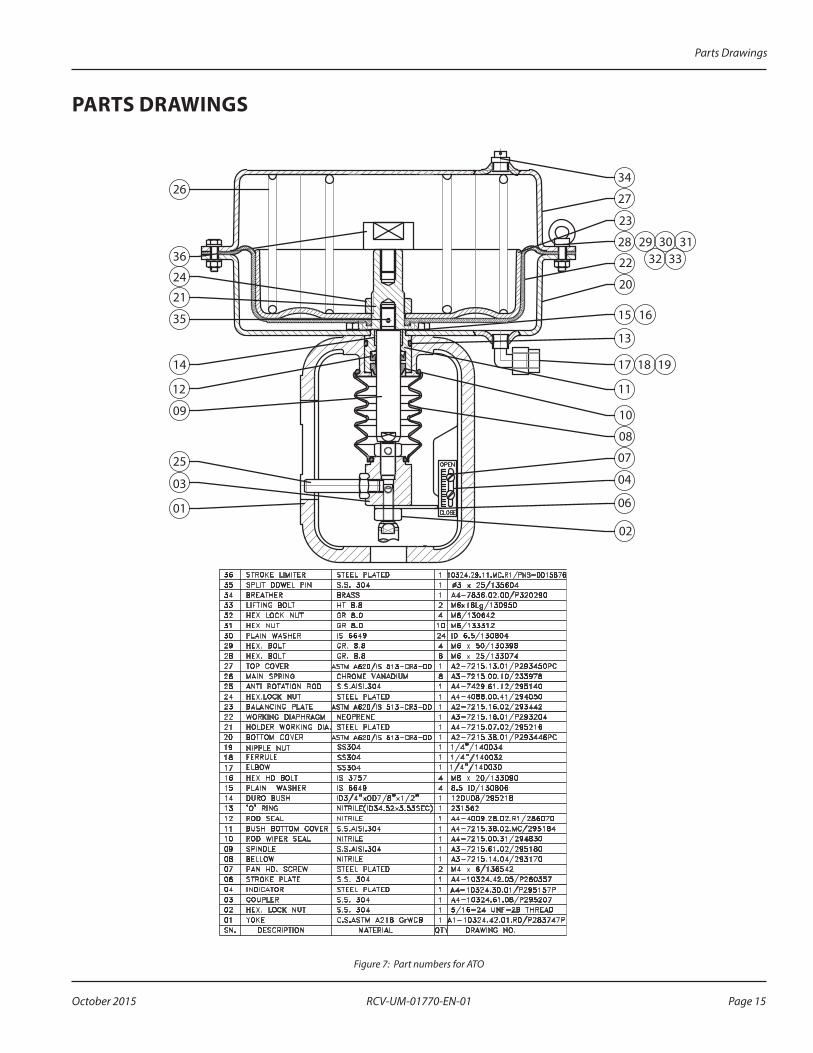
PARTS DRAWINGS
26
36
24
21
35
14
12
09
25
03
01
02
06
04
07
08
10
11
17 18 19
13
15 16
20
22 32 3328 29 30 31
23
27
34
Figure 7: Part numbers for ATO
Parts Drawings
Page 15 October 2015 RCV-UM-01770-EN-01

26
36
24
21
35
14
12
09
25
03
01
02
06
04
07
08
10
11
17 18 19
13
15 16
20
22 32 3328 29 30 31
23
27
34
Figure 8: ATC
Valve Actuators, Type PA58 Multi-Spring Pneumatic Actuator
www.badgermeter.com
Research Control is a registered trademark of Badger Meter, Inc Other trademarks appearing in this document are the property of their respective entities Due to continuous research, product improvements and enhancements, Badger Meter reserves the right to change product or system specifications without notice, except to the extent an outstanding contractual obligation exists © 2015 Badger Meter, Inc All rights reserved
The Americas | Badger Meter | 4545 West Brown Deer Rd | PO Box 245036 | Milwaukee, WI 53224-9536 | 800-876-3837 | 414-355-0400México | Badger Meter de las Americas, S.A. de C.V. | Pedro Luis Ogazón N°32 | Esq. Angelina N°24 | Colonia Guadalupe Inn | CP 01050 | México, DF | México | +52-55-5662-0882Europe, Middle East and Africa | Badger Meter Europa GmbH | Nurtinger Str 76 | 72639 Neuffen | Germany | +49-7025-9208-0Europe, Middle East Branch Office | Badger Meter Europe | PO Box 341442 | Dubai Silicon Oasis, Head Quarter Building, Wing C, Office #C209 | Dubai / UAE | +971-4-371 2503 Czech Republic | Badger Meter Czech Republic s.r.o. | Maříkova 2082/26 | 621 00 Brno, Czech Republic | +420-5-41420411Slovakia | Badger Meter Slovakia s.r.o. | Racianska 109/B | 831 02 Bratislava, Slovakia | +421-2-44 63 83 01Asia Pacific | Badger Meter | 80 Marine Parade Rd | 21-06 Parkway Parade | Singapore 449269 | +65-63464836China | Badger Meter | 7-1202 | 99 Hangzhong Road | Minhang District | Shanghai | China 201101 | +86-21-5763 5412
Control. Manage. Optimize.


