39
User Manual Yacht Devices Circuit Control YDCC-04 Yacht Devices Switch Control YDSC-04 Firmware version 1.01 2018

User Manual
Yacht Devices Circuit Control YDCC-04Yacht Devices Switch Control YDSC-04
Firmware version1.01
2018

© 2018 Yacht Devices Ltd. Document YDCCSC-04-002. December 13, 2018. Web: http://www.yachtd.com/
Yacht Devices Circuit Control and Yacht Devices Switch Control are certified by the National Marine Electronics Association. NMEA 2000® is a registered trademark of the National Marine Electronics Association.
Contents
Introduction 4
Warranty and Technical Support 5
I. Circuit Control YDCC-04 Specification 6
II. Switch Control YDSC-04 Specification 8
III. Digital Switching Products Overview 10
IV. Digital Switching System Examples 12
V. Device Installation and Connection to NMEA 2000 17
VI. Connection of LEDs, Buttons and Loads 19
VII. Device Programming and Settings 24
VIII. LED Signals 30
IX. Firmware Updates 32
X. Control from a MFD with CZone Support 34
Appendix А. Troubleshooting 35
Appendix B. Device Connectors 36
Appendix C. Device LEDs, Connectors and Terminals 37
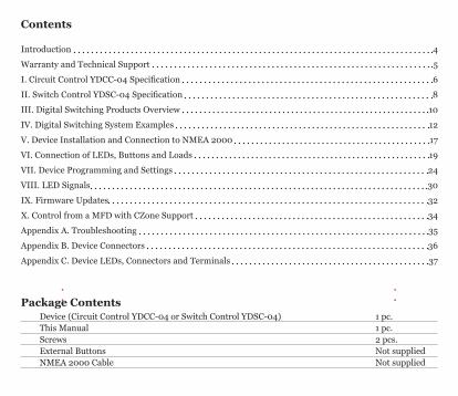
Package ContentsDevice (Circuit Control YDCC-04 or Switch Control YDSC-04) 1 pc. This Manual 1 pc. Screws 2 pcs.External Buttons Not supplied NMEA 2000 Cable Not supplied

— 4 —
Introduction
This Manual contains information on how to install, configure and operate Yacht Devices Circuit Control YDCC-04 (hereinafter Circuit Control) and Yacht Devices Switch Control YDSC-04 (hereinafter Switch Control) intended for use on leisure crafts.
The Circuit Control and Switch Control (hereinafter, where the differences are not critical, Devices) are key components of the digital switching system uses a NMEA 2000 network to transmit switching signals. Digital switching reduces complexity and saves on cabling in comparison to traditional systems, and gives control over a boat’s equipment from other hardware and software. It also open doors for «smart boat» automation.
The Circuit Control contains four latching (bi-stable) relays capable of switching the direct current (DC) and alternating current (AC) loads, which can be managed from connected control buttons with LED indicators or over NMEA 2000 with standard messages.
The Switch Control is designed to set up additional control posts with duplicate physical buttons and LED indication. It is also compatible with other NMEA 2000 digital switching devices managed with standard NMEA 2000 PGNs 127501 and 127502.
Both products have terminals for connection of momentary push buttons with an LED indication. External buttons are not supplied with Devices; you can choose any to match your boat’s interior.
The Circuit Control unit can work in parallel with other units and can be managed from multiple Switch Control units with a matched bank number (all Devices with factory settings have a bank number of zero). The bank number of the Device can be changed using the connected buttons or NMEA 2000 commands.
Section III of this Manual briefly describes other products, which can become a part or your digital switching system.
The Circuit Control and Switch Control are designed for operating in an NMEA 2000 network and are supplied with NMEA 2000 Micro Male connectors. Drop cables are not supplied with Devices and must be purchased separately. For NMEA 2000 networks with proprietary connectors (Raymarine SeaTalk NG, Smirad SimNet), a cable adapter is required.
We thank you for purchasing our Devices and wish you happy voyages!

— 5 —
Warranty and Technical Support
1. The Device warranty is valid for two years from the date of purchase. If a Device was purchased in a retail store, the sale receipt may be requested when applying for a warranty claim.
2. The Device warranty is terminated in case of violation of the instructions of this Manual, case integrity breach, or repair or modification of the Device without manufacturer’s written permission.
3. If a warranty request is accepted, the defective Device must be sent to the manufacturer.
4. The warranty liabilities include repair and replacement of the goods and do not include the cost of equipment installation and configuration, neither shipping the defective Device to the manufacturer.
5. Responsibility of the manufacturer in case of any damage as a consequence of Device operation or installation is limited to the Device cost.
6. The manufacturer is not responsible for any errors and inaccuracies in guides and instructions of other companies.
7. The Device requires no maintenance. The Device’s case is non-dismountable. In the event of a failure, please refer to Appendix A before contacting technical support.
8. The manufacturer accepts applications under the warranty and provides technical support only via e-mail or through authorized dealers.
9. Contact details of the manufacturer and a list of the authorized dealers are published on the website: http://www.yachtd.com/.

— 6 —
I. Circuit Control YDCC-04 Specification
Figure 1. Schematic of the Circuit Control YDCC-04

— 7 —
Device parameter Value Unit
Operating voltage (from an NMEA 2000 network) 7..16 V
Protection against reverse polarity Yes —
NMEA 2000 consumption current, (average / peak) 30 / 130 mA
Load Equivalency Number 3 LEN
Operating temperature range -40..+80 °С
Weight 170 g
Device case dimensions (LxWxH) 92x72x38 mm
Number of relays (channels) 4 —
Maximum switching voltage, AC 400 V
Maximum constant load current per relay (channel) 10 A
Peak relay current (4 seconds, duty cycle 10%) 20 A
Clamp terminal block maximum wire diameter 2,0 mm
Breakdown voltage between control circuits and relay load contacts 5000 VRMS
Yacht Devices Ltd declares that this product is compliant with the essential requirements of EMC directive 2014/30/EU and radio and TTE directive 1999/5/EC. Dispose of this product in accordance with the WEEE Directive. Do not mix electronic disposal with domestic or industrial refuse.

— 8 —
II. Switch Control YDSC-04 Specification
Figure 1. Drawing of the Switch Control YDSC-04

— 9 —
Device parameter Value Unit
Operating voltage (from an NMEA 2000 network) 7..16 V
Protection against reverse polarity Yes —
NMEA 2000 consumption current, max 30 mA
Load Equivalency Number 1 LEN
Operating temperature range -40..+80 °С
Weight 75 g
Device case dimensions (LxWxH) 85x45x28 mm
Clamp terminal block maximum wire diameter 2,0 mm
Yacht Devices Ltd declares that this product is compliant with the essential requirements of EMC directive 2014/30/EU and radio and TTE directive 1999/5/EC.
Dispose of this product in accordance with the WEEE Directive. Do not mix electronic disposal with domestic or industrial refuse.
— 10 —
III. Digital Switching Products Overview
Products described in this section can be a good addition to your digital switching system.
1. Yacht Devices NMEA 2000 Wi-Fi Gateway YDWG-02
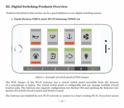
Figure 1. Example of switch panel of Web Gauges
The Web Gauges of the Wi-Fi Gateway has a virtual switch panel accessible from the browser of a smartphone or laptop. The virtual switch panel is configurable and can manage multiple Circuit Control units. The Gateway also supports configuration (see Section VII) and updating the firmware (see Section IX) of both Circuit Control and Switch Control.
The Gateway can establish its own Wi-Fi network or connect to a boat’s existing Wi-Fi. If you have access

— 11 —
to the Wi-Fi of your boat remotely, Web Gauges will allow you to monitor your boat and manage loads anywhere and from any device.
2. Yacht Devices NMEA 2000 Sensors
Humidity Sensor YDHS-01, Digital Barometer YDBC-05, Digital Thermometer YDTC-13 and Exhaust Gas Sensor YDGS-01 can be programmed to turn channels of Circuit Control on and off over an NMEA 2000 network.
One Thermometer can manage up to six channels using triggers based on actual temperature. It can be used, for example, to turn the seawater pump on when the temperature in live well is high, and turn on the alarm if the pump is broken and the temperature continues to rise.
The Humidity Sensor operates by relative humidity, air temperature and the difference between actual temperature and dew point; this allows you to ventilate your boat automatically or warn about oncoming fog. The Barometer can turn channels on and off depending on actual atmospheric pressure or the pressure trend.
For more information, please see the Section «Digital Switching Support» in the Manual of the given product.
3. Chart plotters and other third party products
You can manage loads connected to the Circuit Control from most modern chart plotters with CZone support. This includes Garmin, Lowrance, Simrad, B&G, Furuno and recent models from Raymarine (Axiom, eS and gS series). Please see the Section X for details.
The Circuit Control and Switch Control should be compatible with Oceanic Systems, Offshore Systems, Maretron and Carling Tech displays and relay modules (special setting is required for Maretron and Carling Tech products, see the Section VII).
EmpirBus digital switching products are not supported yet.

— 12 —
IV. Digital Switching System Examples
This section describes possible scenarios of Devices usage.
1. Basic system, with single Circuit Control unit
The simplest system (see the Figure 1 on the next page) includes a single Circuit Control unit with loads, a DIY control panel (not supplied with the Device) with buttons and channel status LEDs connected.
Loads can be managed from the buttons connected to the Circuit Control or over the NMEA 2000 network. For example, you can manage loads from a web browser (see Fig. 1 in the previous section) on a smartphone or laptop connected to the network with our NMEA 2000 Wi-Fi Gateway YDWG-02.
Loads can also be managed automatically by our NMEA 2000 environmental sensors (see III.2) to maintain the temperature in the live well, ventilate the boat, etc.

— 13 —
Figure 1. Basic system example

— 14 —
2. Typical system, with one or multiple control panels
To manage loads from multiple locations using hardware buttons, you need to install additional Switch Control units with a matching bank number (see Section VII). The number of Switch Control units is limited only by the network’s capacity. You may have multiple digital switching systems (differing only in bank number) installed on one NMEA 2000 network.
Figure 2. Typical installation example
— 15 —
This system shown in Figure 2 may have only one control panel (connected to Switch Control) and be used to remotely control new loads from the main post (near the helm or chart table) when routing of additional cables to loads location is difficult.
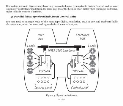
3. Parallel loads, synchronized Circuit Control units
You may need to manage loads of the same type (lights, ventilation, etc.) in port and starboard hulls of a catamaran, or on the lower and upper decks of a motor boat, etc.
Figure 3. Synchronized loads

— 16 —
Digital switching saves on cables, and in most cases you will only need to have power and NMEA 2000 cables in each location, instead of routing an individual cable for each load from the central switch panel.
Two or more Circuit Control units with the same bank number will work in parallel. Commands from buttons connected to a single unit will be also be sent to all others. In a case where one unit is turned off, it will synchronize its state with other units when powered on. In this situation, the Circuit Control unit with the lowest serial number will have priority (does not matter what unit stays on longer or which is turned on first), and the unit with higher serial number will set the state of its relays to the state of the unit with highest priority.
The Device’s serial number can be found at the bottom side of the Device or you can check it in the list of devices on a chart plotter (see Figure 1 in Section V).

— 17 —
V. Device Installation and Connection to NMEA 2000
The Device requires no maintenance. When deciding where to install the Device, choose a dry mounting location. Despite the fact that the Device case is waterproof, its wire terminals are open and seawater can cause a short circuit. Do not place the Device where it can be flooded by water, get wet in the rain or be sprayed by water.
The Device has two mount holes (see Fig.1 in Sections I and II), 4 mm in diameter. Use the screws supplied to fix the Device on the flat surface in any orientation.
The location of Device connectors, LEDs and terminals is shown in Appendix C.
The Device should be connected to the NMEA 2000 network backbone with a NMEA 2000 drop cable (not supplied with the Device). For networks with proprietary connectors (Raymarine SeaTalk NG, Smirad SimNet), a cable adapter is required.
Before connecting the Device, turn off the bus power supply. Refer to the following documents if you have any questions regarding the use of connecting cables, terminators or connectors:
• Technical Reference for Garmin NMEA 2000 Products (190-00891-00) for standard NMEA 2000 networks
• SeaTalk NG Reference Manual (81300-1) for Raymarine network
After connecting the Device, close the lock on the connector to ensure its water resistance and reliability.
Devices are supplied with the bank number programmed to zero. For newly installed Devices, this means that all Circuit Control units will work in parallel (see IV.3) and pressing the button on any Circuit Control or Switch Control unit will cause switching of the corresponding channel for all Circuit Controls.
When adding a new Circuit Control to the network, note that it can cause switching of channels on previously installed Circuit Control units with the bank number of zero.
— 18 —
Independent digital switching systems in a single NMEA 2000 network should have different bank numbers. Changing the bank number is described in Section VII.
After turning on the NMEA 2000 network power supply, the Device will produce one short signal of the Device status LED, indicating that the Device is functioning.
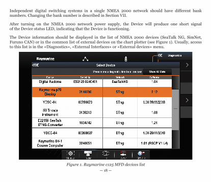
The Device information should be displayed in the list of NMEA 2000 devices (SeaTalk NG, SimNet, Furuno CAN) or in the common list of external devices on the chart plotter (see Figure 1). Usually, access to this list is in the «Diagnostics», «External Interfaces» or «External devices» menu.
Figure 1. Raymarine c125 MFD devices list

— 19 —
VI. Connection of LEDs, Buttons and Loads
The location of Device connectors, LEDs and terminals is shown in Appendix C.
1. Connecting buttons and status LEDs
On both Devices, each load channel can be individually controlled by a normally open momentary push-button, connected to the corresponding terminal (B1-B4, Fig.1).
Pressing the button causes the built-in button’s LED to signal, and inverts the channel’s state indicated by the corresponding built-in channel status LED (see Appendix C) and the external status LED connected to the terminals (L1-L4, Fig.1).
Note that the built-in status LEDs can be turned off in Device settings (see VII) to save energy.
You can use any momentary push-button you like that matches your boat’s interior. Waterproof IP67 buttons of this type with integrated colored LED are widely available from well-known international suppliers like DigiKey Electronics (www.digikey.com), Mouser Electronics (www.mouser.com) and others.
All connections should be made when the power is off. This will protect against accidental short circuits during installation.
— 20 —
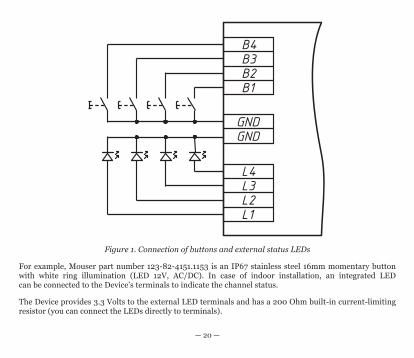
Figure 1. Connection of buttons and external status LEDs
For example, Mouser part number 123-82-4151.1153 is an IP67 stainless steel 16mm momentary button with white ring illumination (LED 12V, AC/DC). In case of indoor installation, an integrated LED can be connected to the Device’s terminals to indicate the channel status.
The Device provides 3.3 Volts to the external LED terminals and has a 200 Ohm built-in current-limiting resistor (you can connect the LEDs directly to terminals).

— 21 —
Buttons with LEDs rated as «12V» will be brighter than the same buttons rated as «24V» (they actually differ in the current-limiting resistor inside). The specified voltage is the maximum allowed and both types are compatible with the Device; buttons with «5V» and «3V» LEDs are also widely available.
In the outdoor installation, the LEDs of integrated buttons can be assigned to button illumination and an additional LED should be installed to indicate the channel’s state. You can choose any LED with forward current from 10 to 30 mA. Diffused LEDs have a better viewing angle than clear LEDs. LEDs with colorless lenses are better than tinted because even under direct sunlight or sun glare, the on/off state is clearly visible.
For example, Mouser part number 859-LTL2R3FU3JSR, is a usual 5mm 10 mA orange LED with a colorless diffused lens.
The connection scheme is shown in Figure 1. Please make sure to connect the LEDs in correct polarity: the positive terminal (anode) of LED should be connected to the Device’s L1-L4 terminals, and all negative LED terminals (cathodes) should be connected to the common ground (GND terminal).
2. Connecting loads to the Circuit Control
The Circuit Control unit has four latching relays (four «channels»). Up to four independent loads can be connected to the relay outputs. Circuit Control supports both AC and DC loads. Latching (bi-stable) relays consume electricity only during switching, and remains in the last state after Device powering off.
Channel 3 and channel 4 have a normally open contact: when the channel is in the «OFF» state, input and output terminals are disconnected.
Channel 1 and channel 2 have a switching contact (see Figure 2). These channels can be used to select between manual or automatic mode of a bilge pump, between main or backup battery for a single load, and so on.
Circuit Control has no internal overcurrent protection, so each load should have an appropriate rated fuse and/or circuit breaker.
Loads are connected to the clamp terminal block (see Appendix C). It is recommended to crimp a lug

— 22 —
on the wire end before connecting. Choose a wire diameter according to the load current. Always use a marine grade power cable with proper voltage, current, temperature and water/oil resistance ratings.
Figure 2. Example of connecting loads
— 23 —
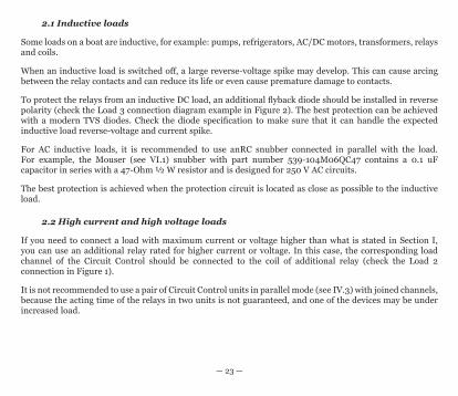
2.1 Inductive loads
Some loads on a boat are inductive, for example: pumps, refrigerators, AC/DC motors, transformers, relays and coils.
When an inductive load is switched off, a large reverse-voltage spike may develop. This can cause arcing between the relay contacts and can reduce its life or even cause premature damage to contacts.
To protect the relays from an inductive DC load, an additional flyback diode should be installed in reverse polarity (check the Load 3 connection diagram example in Figure 2). The best protection can be achieved with a modern TVS diodes. Check the diode specification to make sure that it can handle the expected inductive load reverse-voltage and current spike.
For AC inductive loads, it is recommended to use anRC snubber connected in parallel with the load. For example, the Mouser (see VI.1) snubber with part number 539-104M06QC47 contains a 0.1 uF capacitor in series with a 47-Ohm ½ W resistor and is designed for 250 V AC circuits.
The best protection is achieved when the protection circuit is located as close as possible to the inductive load.
2.2 High current and high voltage loads
If you need to connect a load with maximum current or voltage higher than what is stated in Section I, you can use an additional relay rated for higher current or voltage. In this case, the corresponding load channel of the Circuit Control should be connected to the coil of additional relay (check the Load 2 connection in Figure 1).
It is not recommended to use a pair of Circuit Control units in parallel mode (see IV.3) with joined channels, because the acting time of the relays in two units is not guaranteed, and one of the devices may be under increased load.
— 24 —
VII. Device Programming and Settings
Programming of the Device should not be performed at sea.
The most important setting is the bank number, it should match on Devices working together; independent digital switching systems in one NMEA 2000 network should have different bank numbers.
The bank number of the Device can be changed using the connected buttons (see VII.1) or using a special installation description string (see VII.2) which can be entered for the Device in a compatible chart plotter or in special PC software.
Status LEDs on the Device’s case are usually used during installation only. You can turn off the built-in status and button LEDs with both programming methods; this reduces the average current consumption of the Device from 30 to 18 mA.
Other settings described in this Section are not required for typical installation.
1. Programming with buttons
You can program a relay group (bank number) using the buttons connected to the Device. Bank numbers from 0 to 7 can only be set using this method, for the rest of the range (8-252), use the method described in VII.2.
To enter the bank’s programming mode, press and hold buttons 1 and 4, then, still holding buttons 1 and 4, also press and hold buttons 2 and 3. Keep holding all four buttons for three seconds. The channel status and button status LEDs should go OFF for a half of a second and then the current bank number will be indicated.
The number of lit LEDs equals the bank number minus one (1 LED means bank 0, 2 LEDs — bank 1, etc.). If the bank number was already programmed and set higher than 7, all eight load and button status LEDs will slowly blink with 1 second interval.
Now the Device is in programming mode and you can release the buttons.

— 25 —
Button B1 decreases the bank number by one (and resets any bank over 7 to 7), B2 increases it (and resets any bank number over 7 to 0), B3 saves the changes and exits bank programming mode, B4 exits without saving.
You can also turn on and off built-in LEDs, support Maretron products and support chart plotters with CZone using this method. See the settings description in the next chapter.
To enter the settings programming mode, press and hold buttons 2 and 3 and then, still holding buttons 2 and 3, also press and hold buttons 1 and 4. Keep holding all four buttons for three seconds. The channel status and button status LEDs should go OFF for a half of a second and then display the current settings:
• the L1 LED (state of the channel 1) is on, if the built-in LEDs are not OFF;• the L2 LED is on, if Maretron support is ON;• the L3 LED is on (Circuit Control only), if CZone support is ON (not OFF or AUTO).
Button B1 toggles the current setting ON or OFF, B2 moves selection to the next setting (its LED will blink several times to indicate the selection), B3 saves the changes and exits setting programming mode, B4 exits without saving.
Note, that LED and CZone settings may have other values than ON and OFF (please, see the next chapter for details). If you do not toggled the setting, its value does not changing at saving, but if you toggle it at least once, it will be saved as ON or OFF.
2. Programming with Installation Description String
Installation description strings are usually written by installers to specify the device location or to leave notes or contact information.
This method requires a compatible MFD or special PC software like CAN Log Viewer from our company, ActiSense NMEA Reader or Maretron N2KAnayzer, and a gateway interface between the PC and NMEA 2000 network (for example, our NMEA 2000 USB Gateway YDNU-02 or NMEA 2000 Wi-Fi Gateway YDWG-02).
To program the Device, enter a special string starting with «YD:» (see Table 1) to the installation description field 2 in the Device properties. For example, «YD:DEV 1» (without quotes) will change the NMEA 2000 device instance of the Device to 1.

— 26 —
If the command is accepted by the Device, it will add «DONE» to the entered text and «YD:DEV 1 DONE» will be displayed in the case of our example. Note that the Device always accepts correct strings regardless of the current settings, etc.
On Figure 1, you can see the process of programming the Device with free CAN Log Viewer software (to open this window, select the item «NMEA 2000 Devices» in the «View» menu, refresh the list of devices, select the device and click «Properties» button). You can download this program (it supports Microsoft Windows, Mac OS X and Linux) at http://www.yachtd.com/downloads/.
Using this software, you can also modify the NMEA 2000 device instance by entering a value in the dedicated field (see «Address Claim» group on the screenshot).
After entering the command (as shown on Figure 1) click «Update» button to apply changes, the value in the «Device Instance» field will be changed to 1, and the «Installation Details 2» field will be changed to «YD:DEV 1 DONE».

— 27 —
Figure 1. Programming with CAN Log Viewer

— 28 —
Table 1. Special strings for Circuit Control and Switch Control
String format Examples DescriptionYD:RESET YD:RESET Reset device settings to the default values.
This command also clears both installation description strings (no answer with «DONE»).
YD:DEV <number> YD:DEV 1 Set NMEA 2000 device instance value (0–255). Factory setting: 0.
YD:SYS <number> YD:SYS 3 Set NMEA 2000 system instance value (0–15). Factory setting: 0.
YD:BANK <number> YD:BANK 2YD:BANK
Set the relay group (bank) number (0–252). Factory setting: 0. See note 3.
YD:MARETRON <ON|OFF>
YD:MARETRON ONYD:MARETRON OFFYD:MARETRON
Factory setting: OFF. Compatibility mode for Maretron and Carling Tech equipment (Notes 1, 3).
YD:LED <ON|OFF>YD:LED <minutes>
YD:LED ONYD:LED OFFYD:LED 50YD:LED
Built-in LED operation mode.ON (default) — enable all built-in LED signals;OFF — disable built-in LEDs, except the Device status LED;Number from 0 to 180 — turn off built-in LEDs after the specified number of minutes has elapsed after the Device is powered on. See note 3.
YD:OFF <number> YD:OFF 1 Turn the corresponding load channel (1–4) OFF.
YD:ON <number> YD:ON 3 Turn the corresponding load channel (1–4) ON.
YD:TOGGLE <number> YD:TOGGLE 4 Toggle the corresponding load channel (1–4).

— 29 —
String format Examples DescriptionYD:CZONE <ON|OFF|AUTO>
YD:CZONE ONYD:CZONE AUTOYD:CZONE OFFYD:CZONE
Circuit Control only. Factory setting: AUTO. Activates features required to control loads from chart plotters with CZone support. See Section X for details. See note 3.
YD:PGN 127501 <interval>
YD:PGN 127501 60000YD:PGN 127501 50YD:PGN 127501 0YD:PGN 127501
Circuit Control only. Set transmitting interval for PGN 127501 (Binary Status Report) in milliseconds. Values from 50 to 60 000 (1 minute) are allowed. Zero value disables periodic transmission of PGN 127501 (Notes 2, 3).
Note 1 : When the Maretron compatibility mode is ON, the Device sends the command message PGN 126208 «Group Function» (for compatibility with Maretron and Carling Tech equipment) after every PGN 127502 «Switch Bank Control» sent.
Note 2: Circuit Control always sends PGN 127501 «Binary Status Report» in response to a command, a request or when channel state is changed. Periodic transmission of this message usually is not required.
Note 3: If no argument is specified, this command displays the current setting value.
Table 1 continued

— 30 —
VIII. LED Signals
The Device is equipped by one bi-color Device’s status LED, four built-in button status LEDs, four built-in channel status LEDs, and four external channel status LEDs can be connected to Device’s terminals. LEDs location shown on drawings in the Appendix C.
Note that the signals of the button and channel status built-in LEDs can be turned off in settings for energy saving (see Section VI).
1. Device’s status LED signals during power on sequence
The Device produces a half-second RED flash after powering on indicating that the Device is successfully initialized.
After initialization, the Device produces three short (quarter of second) GREEN flashes indicating that is has successfully connected to the NMEA 2000 network.
If the device fails to get an NMEA 2000 address, it will constantly flash RED (one second flash with one second intervals).
2. Device’s status LED signals during normal operation
During normal operation, the Device’s status LED produces a short (quarter of second) RED flash each time it sends or receives PGN 127501 «Binary Status Report» or PGN 127502 «Binary Switch Control» with the matching bank number.
3. Channel status signals
The channel status LEDs (built-in and external both) are ON when the channel’s relay connects the «IN» and «ON» terminals (channels 1 and 2) or «IN» and «OUT» terminals (channels 3 and 4). The channels status LEDs are OFF when the relay connects «IN» to «OFF» (channels 1 and 2) or disconnects «IN» from «OUT» (channels 3 and 4).

— 31 —
4. Button status LED signals
The device button status LED is lit while the button is pressed (button terminal is connected with ground terminal, see Figure 1 in Section VI).
If the LED is unlit while button is pressed, be sure that the built-in LEDs are not turned off in settings (see Section VI).
5. Signals during firmware update
Signals during firmware updates are described in the next Section.

— 32 —
IX. Firmware Updates
Firmware updates can be done with free CAN Log Viewer software (version 1.20 or later) running on Microsoft Windows, Mac OS X and Linux:
http://www.yachtd.com/products/can_view.html
The program must be connected to an NMEA 2000 network with USB Gateway YDNU-02 or a Wi-Fi Gateway YDWG-02.
You can download the latest firmware version from our website:
http://www.yachtd.com/downloads/
Open the downloaded .ZIP archive with the update and copy the YDCC04.BIN file (for Circuit Control) or YDSC04.bin file (for Switch Control) to the disk. The README.TXT file inside the archive can contain important information regarding the update.
1. Click the «NMEA 2000 Devices» item in the «View» menu.
2. Click the «Refresh» button (see Figure 1 at the next page) in the opened window and wait for the Device to appear in the list.
3. Select the Device and click the «Firmware Update» button.
4. Locate and select the update file on the disk.
5. Wait while the firmware is uploading.
If in doubt, see the video with the update procedure on our web site. During the firmware upload, the Device’s status LED flashes RED very fast. When the firmware is updated, Device status LED gives off five RED half-second signals and the CAN Log Viewer also informs you that the update is successfully done.

— 33 —
Figure 1. Firmware update of Circuit Control YDCC-04

— 34 —
X. Control from a MFD with CZone Support
You can manage loads connected to the Circuit Control (firmware 1.01 or later is required) from most of modern chart plotters with CZone support. This includes Garmin, Lowrance, Simrad, B&G, Furuno chart plotters and recent models from Raymarine (Axiom, eS and gS series).
You need to do the following; the process will take a minute:
1. Visit the product’s page on our website and follow the link to related article.2. Fill the form with the desired button names and download personalized configuration file for your
MFD.3. Turn on CZone support on your MFD and configure the Dip Switch setting.4. Import the configuration file to the MFD (usually, from MicroSD card).
Please, be aware of the following limitations:
1. You can use only one Circuit Control with your chart plotters, because the downloaded file contains the configuration for one Circuit Control unit only and the configuration file must be the same on all chart plotters with activated CZone support.
2. If you already have CZone equipment installed, you will overwrite the exiting CZone configuration with our file and your CZone equipment will not function correctly.
We will remove both limitations in the next version of the firmware.
The Circuit Control has a setting which activates CZone support (see Section VII). With the factory value (AUTO), CZone support is automatically activated on the Circuit Control when the configuration file download from our web site is uploaded to the MFD.
If you have more than one Circuit Control unit in the network, it can cause a conflict, because all units will be activated. To prevent unnecessary activation, switch the CZone setting from AUTO or ON to OFF using any programming method (see Section VII).

— 35 —
Appendix А. Troubleshooting
Fault Possible reasons and solution
The Device status LED does not signal after the Device is turned on
1. No power supply on the bus. Check if the bus power is supplied (NMEA 2000 network requires a separate power connection and cannot be powered by a plotter or another Device connected to the network).
2. Loose connection in the power supply circuit. Treat the Device connector with a spray for cleaning electrical contacts. Plug the Device into another connector.
Device is not displayed in the list of external devices on the plotter, does not send/receive switching commands over NMEA 2000
1. Loose connection in the data circuit. Treat the Device connector with a spray for cleaning electrical contacts. Plug the Device into another connector. 2. There are problems in the NMEA 2000 network. The network segment is not connected to the plotter or there are missing terminators in the network. Plug another device into the selected connector and make sure it appears in the list of devices on the plotter.
Switch Control unit does not control Circuit Control unit
1. Wrong bank number. Paired Switch Control and Circuit Control units should have the same bank number. Configure Devices to use the same bank number (refer to Section VII).
No built-in LED signals 1. Built-in LEDs are turned off in the settings. Enable built-in LEDs with YD:LED ON command (refer to Section VII).
— 36 —
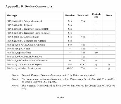
Appendix B. Device Connectors
Message Receive Transmit Period, sec Note
PGN 59392 ISO Acknowledgment Yes Yes —
PGN 59904 ISO Request Yes — —
PGN 60160 ISO Transport Protocol (DT) Yes — —
PGN 60416 ISO Transport Protocol (CM) Yes — —
PGN 60928 ISO Address Claim Yes Yes —
PGN 65240 ISO Commanded Address Yes — —
PGN 126208 NMEA Group Function Yes Yes — 1
PGN 126464 PGN List — Yes —
PGN 126993 Heartbeat — Yes 60
PGN 126996 Product Information — Yes —
PGN 126998 Configuration Information — Yes —
PGN 127501 Binary Status Report Yes YDCC 15 2
PGN 127502 Switch Bank control YDCC Yes — 3
Note 1: Request Message, Command Message and Write Fields are supported.
Note 2: User can change the transmission interval for this message (see Section VII). Transmitted by Circuit Control YDCC-04 only.
Note 3: This message is transmitted by both Devices, but received by Circuit Control YDCC-04 only.

— 37 —
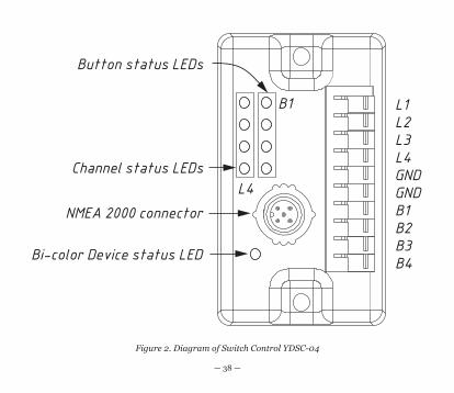
Appendix C. Device LEDs, Connectors and Terminals
Figure 1. Diagram of the Circuit Control YDCC-04
— 38 —
Figure 2. Diagram of Switch Control YDSC-04


