USER MANUAL AVL DITEST ADS 310 AIRCONDITION DIAGNOSTIC SYSTEM ID number: AT7861E Revision: 09 Edition: 03/2020 Firmware version: Data subject to change and errors excepted. All data valid at the time of print. PASSION INNOVATES FUTURE
Transcript
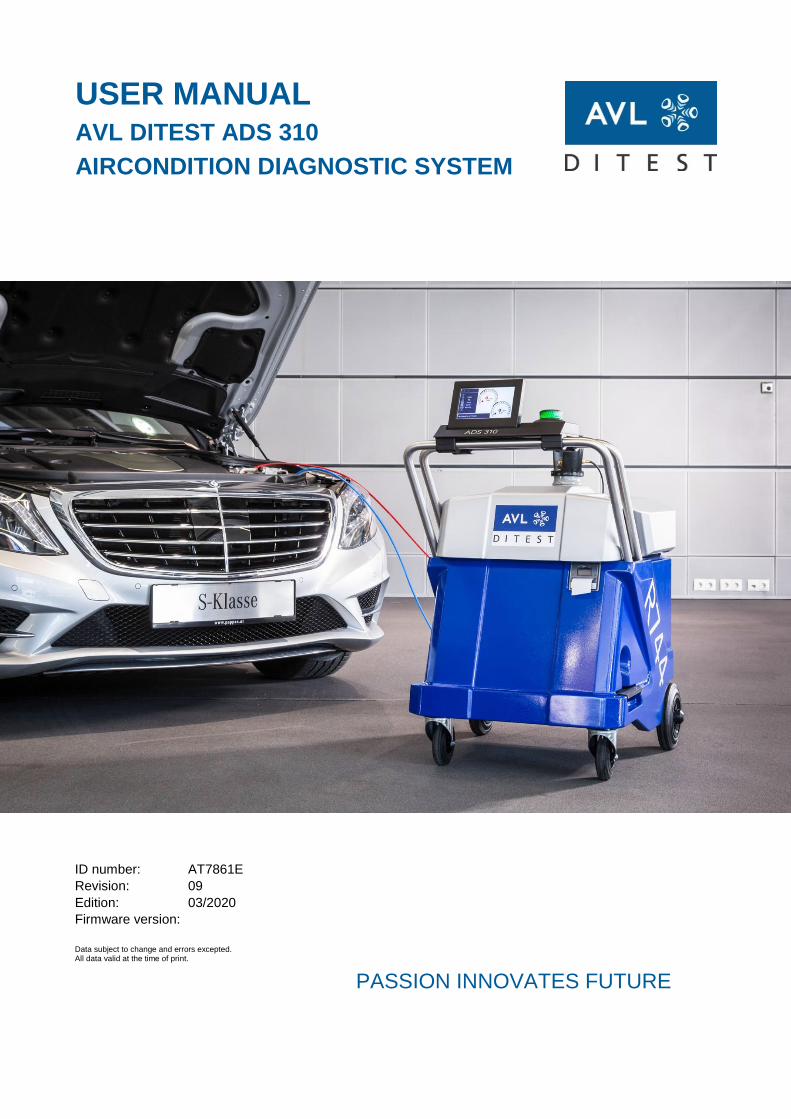
USER MANUAL
AVL DITEST ADS 310
AIRCONDITION DIAGNOSTIC SYSTEM
ID number: AT7861E
Revision: 09
Edition: 03/2020
Firmware version:
Data subject to change and errors excepted. All data valid at the time of print.
The content of this publication may not be reproduced in any way or forwarded to third parties, either in part or in full, without the prior written consent of AVL DiTEST. This publication was created with due care such that AVL DiTEST is not liable for any remaining errors or omissions or for any damages arising therefrom.
This user manual provides an overview of first start-up and the operation of the AVL DiTEST ADS 310. Despite partially giving detailed process descriptions, it does not claim to be comprehensive.
The product is intended only for the highly specific use described in the user manual. The most important prerequisites and safety measures for the use and operation of the product are also described to ensure faultless operation.
No warranty can be given and no liability is assumed for applications exceeding the described intended use, irrespective of observance of the necessary prerequisites and safety measures.
The product must only be used and operated by instructed personnel who, based on their qualifications, are capable of adhering to the necessary safety measures during use and operation. Only accessories and consumables supplied by AVL DiTEST or approved by AVL DiTEST must be used. The measurement results obtained from the product in question depend not only on the correct functioning of the product, but also on a series of general conditions. The results delivered by the product must therefore be evaluated by a specialist (e.g. plausibility check) before further action is taken on the basis of a delivered measurement.
Adjustment and maintenance works on open live devices may only be performed by trained specialists who are aware of the associated danger.
The product may only be repaired in the factory of origin or by specialists specifically trained to perform such repair.
When using the product, it must be ensured by a specialist that the test object or test system is not brought into any operational state that could result in damage to goods or endangerment of people.
Warning and safety notices AVL DiTEST ADS 310
II User Manual
AVL DiTEST ADS 310 SAFETY INSTRUCTIONS
User Manual III
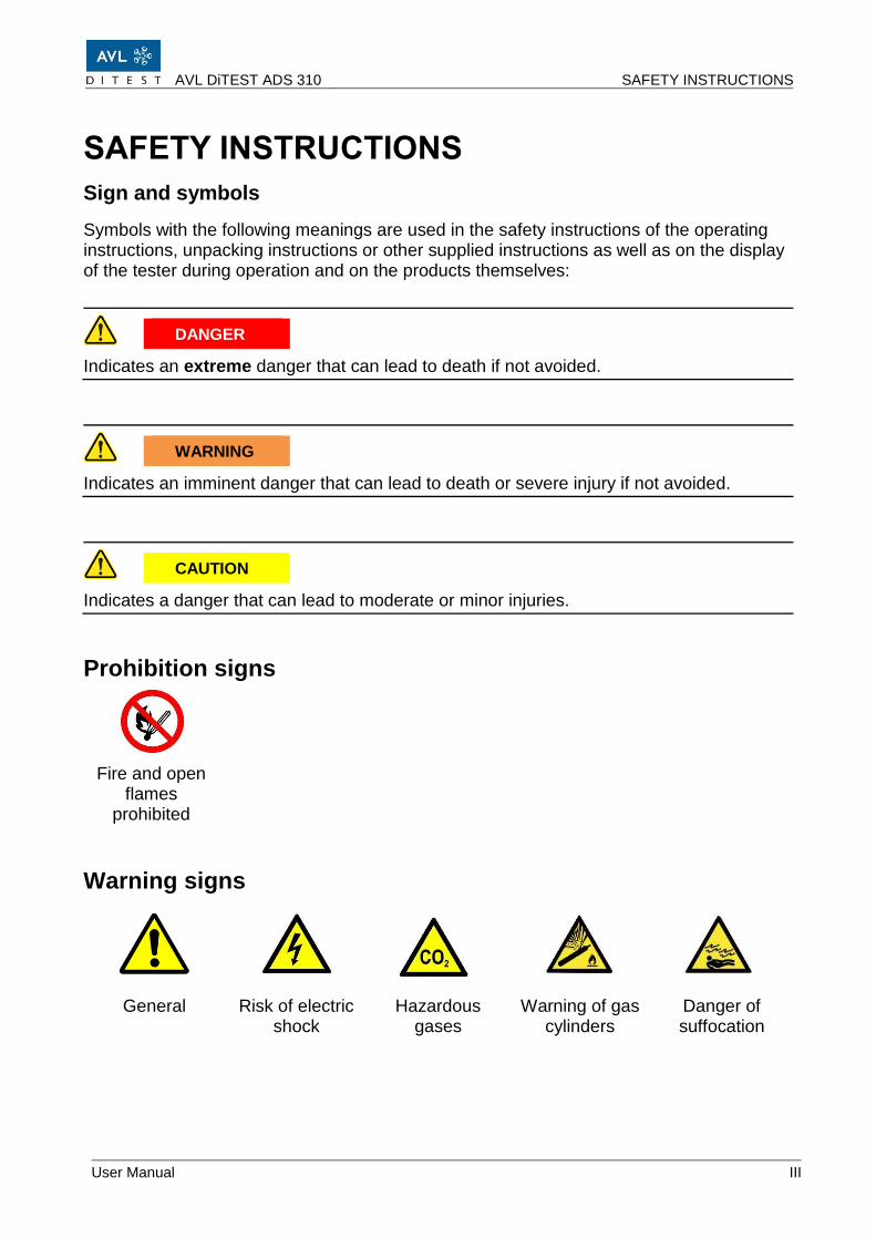
SAFETY INSTRUCTIONS
Sign and symbols
Symbols with the following meanings are used in the safety instructions of the operating instructions, unpacking instructions or other supplied instructions as well as on the display of the tester during operation and on the products themselves:
DANGER
Indicates an extreme danger that can lead to death if not avoided.
WARNING
Indicates an imminent danger that can lead to death or severe injury if not avoided.
CAUTION
Indicates a danger that can lead to moderate or minor injuries.
Prohibition signs
Fire and open flames
prohibited
Warning signs
General Risk of electric shock
Hazardous gases
Warning of gas cylinders
Danger of suffocation
SAFETY INSTRUCTIONS AVL DiTEST ADS 130
IV User Manual
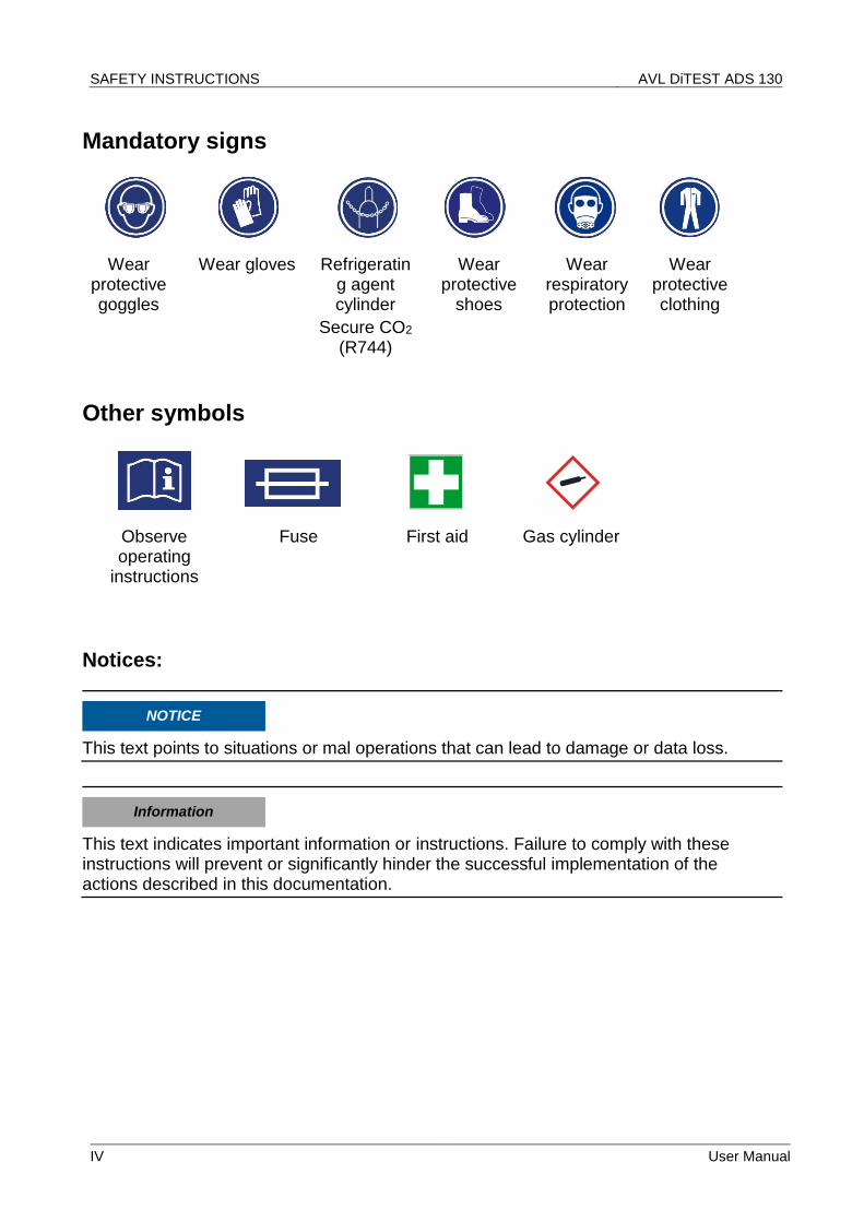
Mandatory signs
Wear protective goggles
Wear gloves Refrigerating agent cylinder
Secure CO2 (R744)
Wear protective
shoes
Wear respiratory protection
Wear protective clothing
Other symbols
Observe operating
instructions
Fuse First aid Gas cylinder
Notices:
NOTICE
This text points to situations or mal operations that can lead to damage or data loss.
Information
This text indicates important information or instructions. Failure to comply with these instructions will prevent or significantly hinder the successful implementation of the actions described in this documentation.
AVL DiTEST ADS 310 SAFETY INSTRUCTIONS FOR CARBON DIOXIDE CO2 (R744)
User Manual V
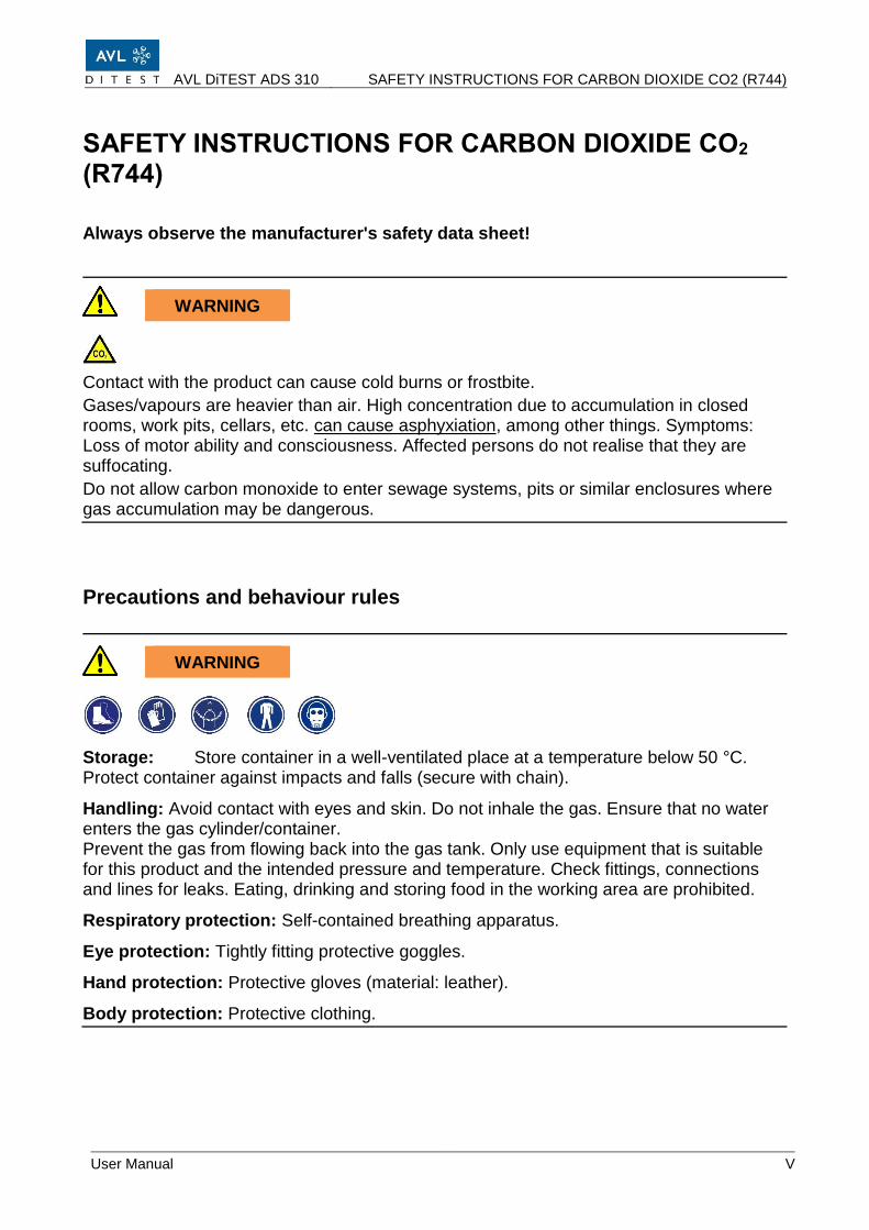
SAFETY INSTRUCTIONS FOR CARBON DIOXIDE CO2 (R744)
Always observe the manufacturer's safety data sheet!
WARNING
Contact with the product can cause cold burns or frostbite.
Gases/vapours are heavier than air. High concentration due to accumulation in closed rooms, work pits, cellars, etc. can cause asphyxiation, among other things. Symptoms: Loss of motor ability and consciousness. Affected persons do not realise that they are suffocating.
Do not allow carbon monoxide to enter sewage systems, pits or similar enclosures where gas accumulation may be dangerous.
Precautions and behaviour rules
WARNING
Storage: Store container in a well-ventilated place at a temperature below 50 °C. Protect container against impacts and falls (secure with chain).
Handling: Avoid contact with eyes and skin. Do not inhale the gas. Ensure that no water enters the gas cylinder/container. Prevent the gas from flowing back into the gas tank. Only use equipment that is suitable for this product and the intended pressure and temperature. Check fittings, connections and lines for leaks. Eating, drinking and storing food in the working area are prohibited.
Hand protection: Protective gloves (material: leather).
Body protection: Protective clothing.
SAFETY INSTRUCTIONS FOR CARBON DIOXIDE CO2 (R744) AVL DiTEST ADS 130
VI User Manual
Behaviour in the event of danger
After a gas leak: Keep unprotected persons away. Ventilate rooms well. Wear protective gear and self-contained breathing apparatus. Close valves / stop gas leak. Avoid entry into cellars, pits and similar enclosures (danger of suffocation).
In case of fire: Wear protective gear and self-contained breathing apparatus. Stop gas leak if possible. Cool cylinders with a water jet from a secure position and remove them from the fire zone if possible to prevent explosion! The product itself is non-flammable.
Extinguishing agents: All known extinguishing agents can be used.
Escape routes: Escape routes must be known to staff.
Accident phone: The accident phone must be known to staff.
First aid
Please observe the instructions for use and safety instructions of your refrigerant supplier.
AVL DiTEST ADS 310 SAFETY INSTRUCTIONS FOR NITROGEN N2
User Manual VII
SAFETY INSTRUCTIONS FOR NITROGEN N2
Always observe the manufacturer's safety data sheet!
WARNING
High concentrations of the gas can cause suffocation.
Loss of motor ability and consciousness.
Rapid release of large quantities creates cold and fog.
Gas may accumulate in cellars, pits, etc., because it is about as heavy as air.
Container may burst or explode in the event of a fire.
Precautions and behaviour rules
WARNING
Employees must be instructed in the use of the gas before being allowed to work with it.
Do not inhale cylinder gas.
Secure cylinders from falling over.
Ensure good ventilation when working.
Filter masks do not protect against asphyxiation!
Wear protective gloves when transporting the cylinder.
Use the cylinder trolley.
Never open valves forcibly (no pliers, etc.)
Store cylinder in well-ventilated location at a temperature <50 °C.
Only use suitable equipment (pressure/temperature/product).
Ensure that no water can enter or flow back into the gas cylinder.
Always close cylinders, even if they are empty, before transporting them and secure with lock not and protective cap.
Lash down cylinders when transporting them in a vehicle. The loading space should be separate from the driver's cab and have vents in the ceiling and floor areas.
SAFETY INSTRUCTIONS FOR NITROGEN N2 AVL DiTEST ADS 130
VIII User Manual
Behaviour in the event of danger
WARNING
Exposure to heat and fire may cause cylinders to burst/explode.
All extinguishing agents can be used.
If gas is escaping, close valve is possible.
Make sure that the gas does not enter cellars, recesses, pits, etc. where gas accumulation might be dangerous (danger of suffocation).
Fire: Remove container from the danger zone or, if this is not possible, cool it with water from a safe distance.
Ensure good ventilation.
In case a large quantity is released or in confined spaces: Evacuate area and enter only with self-contained breathing apparatus. Re-entry only after verification of safe level.
First aid
Please observe the instructions for use and safety instructions of your refrigerant supplier.
AVL DiTEST ADS 310 SAFETY INSTRUCTIONS FOR WORKING ON AIR CONDITIONING SYSTEM
User Manual IX
SAFETY INSTRUCTIONS FOR WORKING ON AIR CONDITIONING SYSTEM
WARNING
The device must not be used if the heating band or cable is damaged. Contact the respective AVL DiTEST branch / AVL DiTEST partner in your country!
NOTICE
The oil level of the vacuum pump must be checked regularly. Top up if necessary. After 60 operating hours a regeneration of the pump oil is necessary (user notification). The regeneration can be performed from the maintenance menu. After 500 operating hours or one year, the pump oil must be changed (user notification). Oil changes can also be performed via the maintenance menu. The pump oil will also be changed as part of the annual servicing of the device by the service partner.
NOTICE
A device check is performed automatically once a week. It can also be triggered manually in the maintenance menu. The device check ensures that the system is sealed and all components are operating correctly. In case of a malfunction, the device will have to be serviced.
NOTICE
The filling levels of the oil/additive containers must be checked at regular intervals. Full used-oil containers must be emptied. Empty clean-oil and UV contrast medium bottles must be refilled if necessary.
SAFETY INSTRUCTIONS FOR WORKING ON AIR CONDITIONING SYSTEM AVL DiTEST ADS 130
X User Manual
NOTICE
Check the available printer paper and replace the paper roll if necessary.
NOTICE
We recommend that you have the device serviced by your service partner once a year. As part of every servicing the vacuum pump oil is changed and the calibration checked. If necessary, a recalibration is performed.
NOTICE
The ADS 310 may only be operated on a level and solid foundation. The refrigerating agent cylinder must be upright in the device. Any tilting may result in incorrect measurements by the cylinder scales and thus incorrect filling quantities!
NOTICE
Open the manual valve of the connected refrigerating agent cylinder before switching on.
If the ADS 310 is not being used, shut of the gas supply by closing the manual valve.
NOTICE
The ADS 310 performs a self-test when it is switched on. This is indicated by the brief sounding of the siren.
NOTICE
If the ADS 310 is not used for a prolonged period, the manual valve must be closed.
AVL DiTEST ADS 310 GENERAL OBLIGATIONS OF THE PERSONNEL
User Manual XI
GENERAL OBLIGATIONS OF THE PERSONNEL
WORKING ON/IN ELECTRICAL COMPONENTS
Opening and working on the electrical components of the ADS 340 may only be carried out by appropriately trained electricians (skilled personnel). Failure to do so may result in danger to life due to dangerous electrical voltage.
OPERATING AND AUXILIARY MATERIALS
Before using operating and auxiliary materials, the material safety data sheets for the
product and the manufacturer's instructions must be read.
An appropriate safety concept must be developed and adhered to based on these material safety data sheets.
GENERAL SAFETY INSTRUCTIONS AVL DiTEST ADS 130
XII User Manual
GENERAL SAFETY INSTRUCTIONS
WARNING
Read all instructions carefully!
DANGER
Danger of life due to electrical voltage
The cylinder heater is operated via the mains voltage! Only connect/disconnect the ADS 310 when it is switched off.
WARNING
Change the gas cylinder only with assembly gloves. When changing the gas cylinder, touching with unprotected hands the not yet installed gas cylinder with connected heating cable and the air conditioner with unprotected hands can cause an unpleasant but harmless electrical discharge.
CAUTION
The weight can result in persons or body parts being trapped. Ensure wheel brakes are applied during operation. Ensure that there is a minimum distance of 1.5 m to walls.
KEEP THESE INSTRUCTIONS IN A SAFE PLACE!
AVL DiTEST ADS 310 Contents
User Manual XIII
Contents
Warning and safety notices ......................................................................... I
SAFETY INSTRUCTIONS ............................................................................ III
SAFETY INSTRUCTIONS FOR CARBON DIOXIDE CO2 (R744) ................. V
SAFETY INSTRUCTIONS FOR NITROGEN N2 .......................................... VII
SAFETY INSTRUCTIONS FOR WORKING ON AIR CONDITIONING SYSTEM ............................................................................ IX
GENERAL OBLIGATIONS OF THE PERSONNEL ..................................... XI
WORKING ON/IN ELECTRICAL COMPONENTS ....................................... XI
OPERATING AND AUXILIARY MATERIALS .............................................. XI
GENERAL SAFETY INSTRUCTIONS......................................................... XII
1 General .............................................................................................. 1 1.1 General Description ............................................................................................................ 1
11.4 AVL DiTEST service address ........................................................................................ 11-1
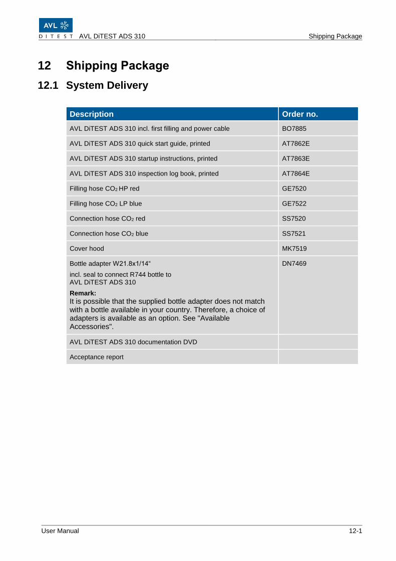
12 Shipping Package ........................................................................ 12-1 12.1 System Delivery ............................................................................................................. 12-1
12.2 Consumables and operating material ............................................................................ 12-2
12.3 Spare parts .................................................................................................................... 12-2
13 Technical Data ............................................................................. 13-1
14 List of Abbreviations ................................................................... 14-1
15 Index ............................................................................................ 15-1
AVL DiTEST ADS 310 General
User Manual 1-1
1 General
1.1 General Description
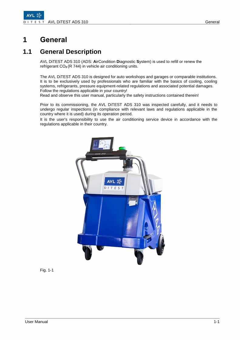
AVL DiTEST ADS 310 (ADS: AirCondition Diagnostic System) is used to refill or renew the refrigerant CO2 (R 744) in vehicle air conditioning units.
The AVL DiTEST ADS 310 is designed for auto workshops and garages or comparable institutions. It is to be exclusively used by professionals who are familiar with the basics of cooling, cooling systems, refrigerants, pressure equipment-related regulations and associated potential damages. Follow the regulations applicable in your country! Read and observe this user manual, particularly the safety instructions contained therein! Prior to its commissioning, the AVL DiTEST ADS 310 was inspected carefully, and it needs to undergo regular inspections (in compliance with relevant laws and regulations applicable in the country where it is used) during its operation period.
It is the user's responsibility to use the air conditioning service device in accordance with the regulations applicable in their country.
Fig. 1-1
General AVL DiTEST ADS 310
1-2 User Manual
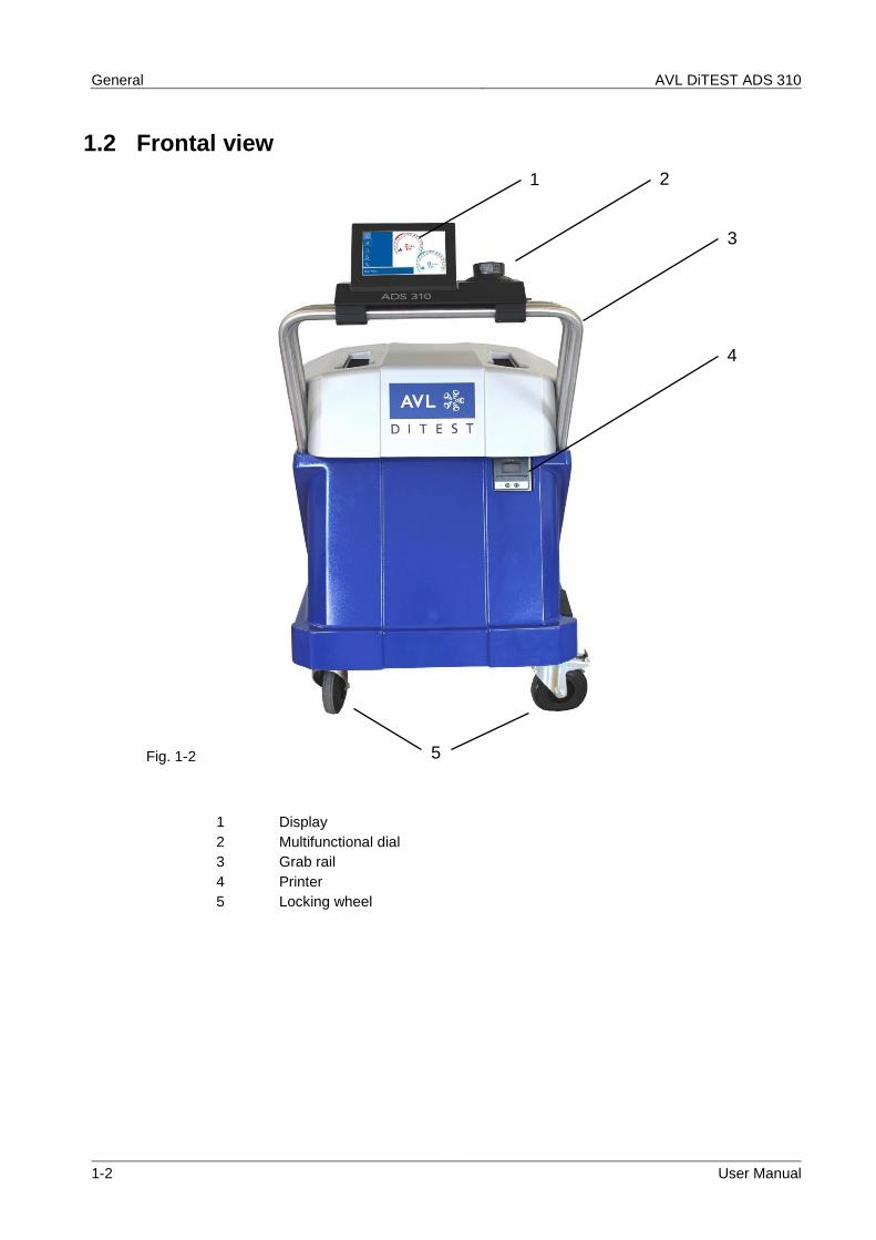
1.2 Frontal view
Fig. 1-2
1 Display
2 Multifunctional dial
3 Grab rail
4 Printer
5 Locking wheel
1
2
3
4
5
AVL DiTEST ADS 310 General
User Manual 1-3
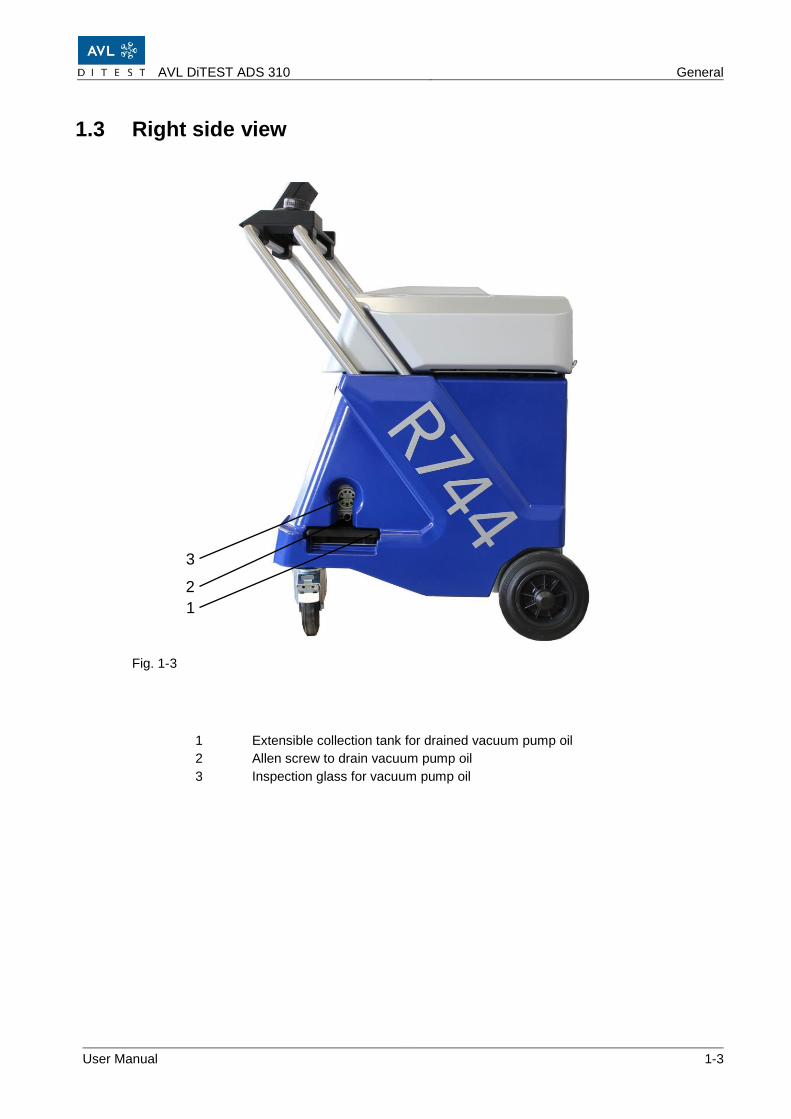
1.3 Right side view
Fig. 1-3
1 Extensible collection tank for drained vacuum pump oil
2 Allen screw to drain vacuum pump oil
3 Inspection glass for vacuum pump oil
1
3
2
General AVL DiTEST ADS 310
1-4 User Manual
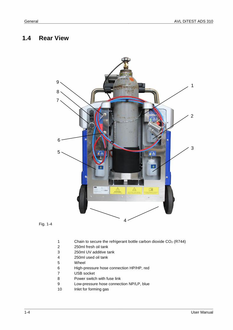
1.4 Rear View
Fig. 1-4
1 Chain to secure the refrigerant bottle carbon dioxide CO2 (R744)
2 250ml fresh oil tank
3 250ml UV additive tank
4 250ml used oil tank
5 Wheel
6 High-pressure hose connection HP/HP, red
7 USB socket
8 Power switch with fuse link
9 Low-pressure hose connection NP/LP, blue
10 Inlet for forming gas
2
3
1
5
7
8
9
6
4
AVL DiTEST ADS 310 General
User Manual 1-5
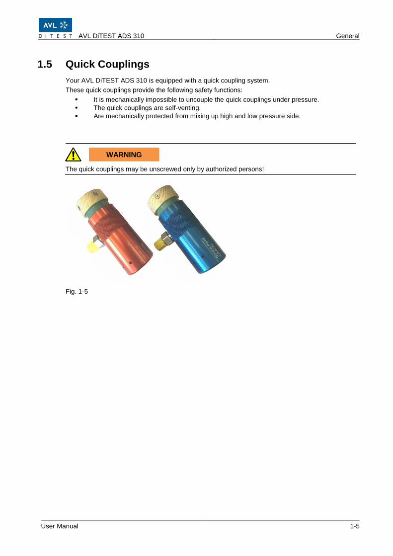
1.5 Quick Couplings
Your AVL DiTEST ADS 310 is equipped with a quick coupling system.
These quick couplings provide the following safety functions:
▪ It is mechanically impossible to uncouple the quick couplings under pressure.
▪ The quick couplings are self-venting.
▪ Are mechanically protected from mixing up high and low pressure side.
WARNING
The quick couplings may be unscrewed only by authorized persons!
Fig. 1-5
General AVL DiTEST ADS 310
1-6 User Manual
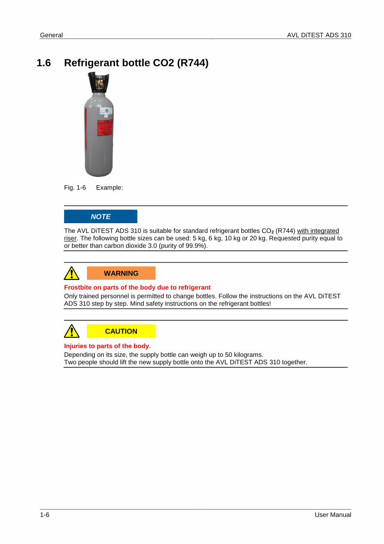
1.6 Refrigerant bottle CO2 (R744)
Fig. 1-6 Example:
NOTE
The AVL DiTEST ADS 310 is suitable for standard refrigerant bottles CO2 (R744) with integrated riser. The following bottle sizes can be used: 5 kg, 6 kg, 10 kg or 20 kg. Requested purity equal to or better than carbon dioxide 3.0 (purity of 99.9%).
WARNING
Frostbite on parts of the body due to refrigerant
Only trained personnel is permitted to change bottles. Follow the instructions on the AVL DiTEST ADS 310 step by step. Mind safety instructions on the refrigerant bottles!
CAUTION
Injuries to parts of the body.
Depending on its size, the supply bottle can weigh up to 50 kilograms. Two people should lift the new supply bottle onto the AVL DiTEST ADS 310 together.
AVL DiTEST ADS 310 General
User Manual 1-7
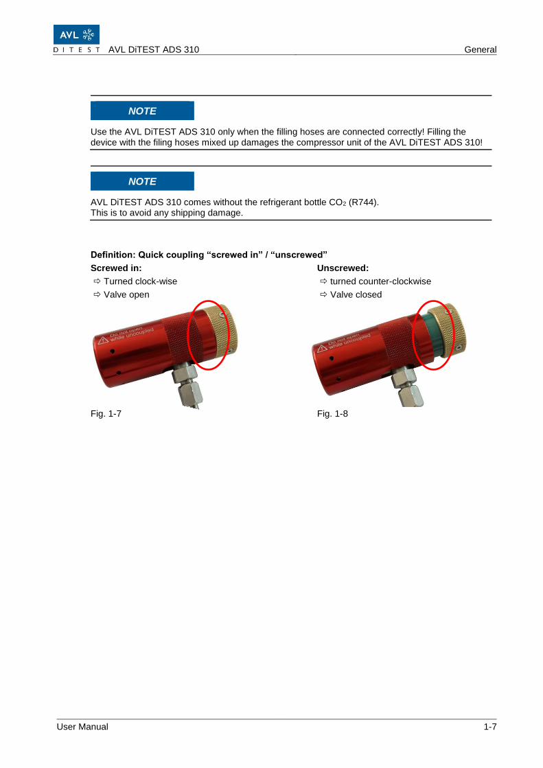
NOTE
Use the AVL DiTEST ADS 310 only when the filling hoses are connected correctly! Filling the device with the filing hoses mixed up damages the compressor unit of the AVL DiTEST ADS 310!
NOTE
AVL DiTEST ADS 310 comes without the refrigerant bottle CO2 (R744). This is to avoid any shipping damage.
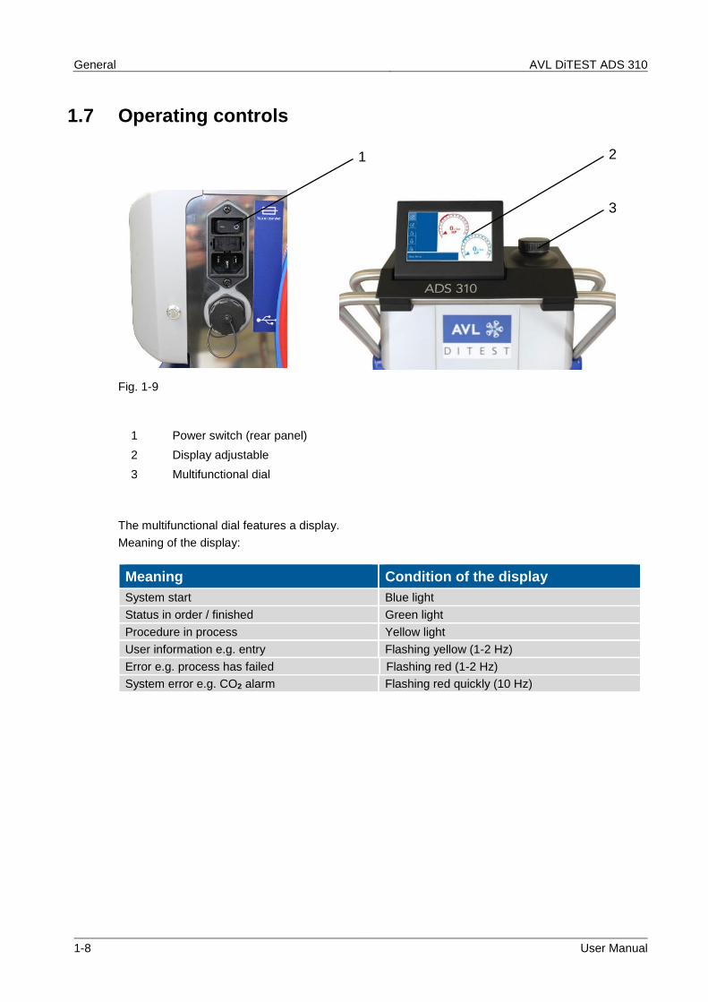
User information e.g. entry Flashing yellow (1-2 Hz)
Error e.g. process has failed Flashing red (1-2 Hz)
System error e.g. CO2 alarm Flashing red quickly (10 Hz)
2
3
1
AVL DiTEST ADS 310 General
User Manual 1-9
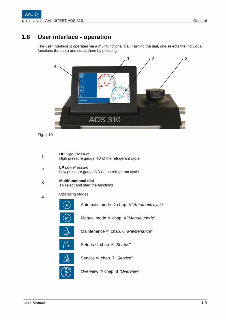
1.8 User interface - operation
The user interface is operated via a multifunctional dial. Turning the dial, one selects the individual functions (buttons) and starts them by pressing.
Fig. 1-10
HP High Pressure High pressure gauge HD of the refrigerant cycle
LP Low Pressure Low pressure gauge ND of the refrigerant cycle
Multifunctional dial To select and start the functions
Operating Modes
Automatic mode chap. 3 "Automatic cycle"
Manual mode chap. 4 "Manual mode"
Maintenance chap. 6 "Maintenance"
Setups chap. 5 "Setups"
Service chap. 7 "Service"
Overview chap. 8 “Overview”
1
2
3
4
4
1 2 3
General AVL DiTEST ADS 310
1-10 User Manual
1.9 User prompts
Up Selects the previous function.
Down Selects the next function.
Back Goes one step back.
Start Starts functions.
Cancel Cancels the ongoing process.
RESET Set values.
OK Starts function, confirms questions with "yes" or "ok". Confirms questions with “no”
Continue Proceeds by one step in the process.
Printing Prints protocols.
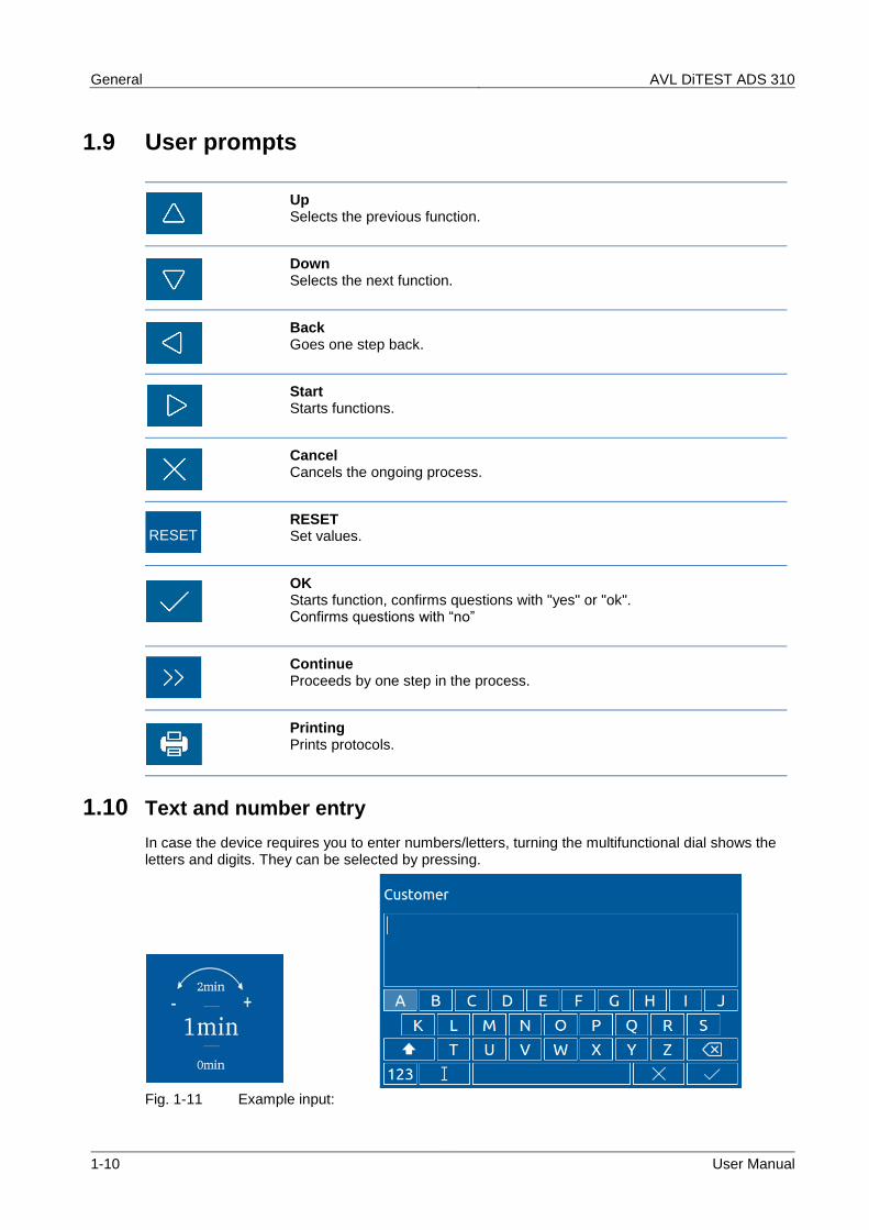
1.10 Text and number entry
In case the device requires you to enter numbers/letters, turning the multifunctional dial shows the letters and digits. They can be selected by pressing.
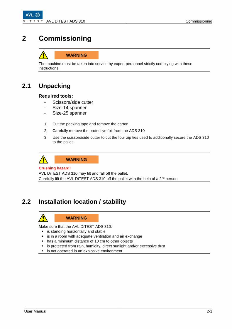
2. Carefully remove the protective foil from the ADS 310
3. Use the scissors/side cutter to cut the four zip ties used to additionally secure the ADS 310 to the pallet.
WARNING
Crushing hazard!
AVL DiTEST ADS 310 may tilt and fall off the pallet.
Carefully lift the AVL DiTEST ADS 310 off the pallet with the help of a 2nd person.
2.2 Installation location / stability
WARNING
Make sure that the AVL DiTEST ADS 310:
▪ is standing horizontally and stable
▪ is in a room with adequate ventilation and air exchange
▪ has a minimum distance of 10 cm to other objects
▪ is protected from rain, humidity, direct sunlight and/or excessive dust
▪ is not operated in an explosive environment
Commissioning AVL DiTEST ADS 310
2-2 User Manual
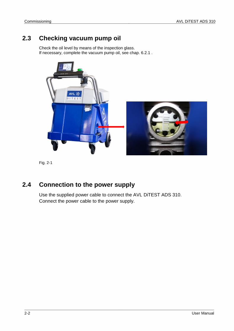
2.3 Checking vacuum pump oil
Check the oil level by means of the inspection glass. If necessary, complete the vacuum pump oil, see chap. 6.2.1 .
Fig. 2-1
2.4 Connection to the power supply
Use the supplied power cable to connect the AVL DiTEST ADS 310.
Connect the power cable to the power supply.
AVL DiTEST ADS 310 Commissioning
User Manual 2-3
2.5 Connecting the refrigerant bottle CO2 (R744)
NOTE
Observe the specifications on the refrigerant bottle CO2 (R744), see chap. 1.6!
NOTE
The AVL DiTEST ADS 310 must not be connected to the vehicle when changing the refrigerant bottle!!
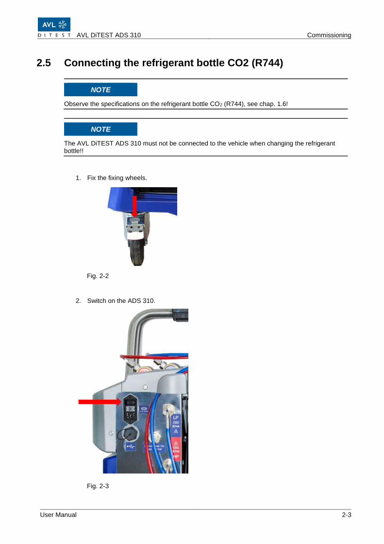
1. Fix the fixing wheels.
Fig. 2-2
2. Switch on the ADS 310.
Fig. 2-3
Commissioning AVL DiTEST ADS 310
2-4 User Manual
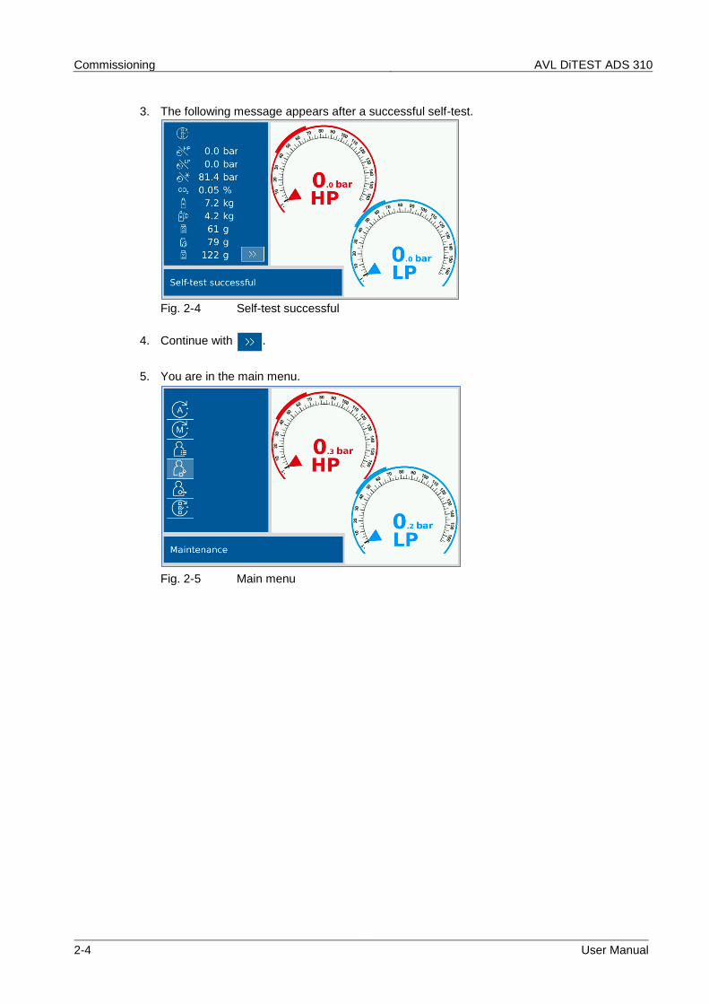
3. The following message appears after a successful self-test.
Fig. 2-4 Self-test successful
4. Continue with .
5. You are in the main menu.
Fig. 2-5 Main menu
AVL DiTEST ADS 310 Commissioning
User Manual 2-5
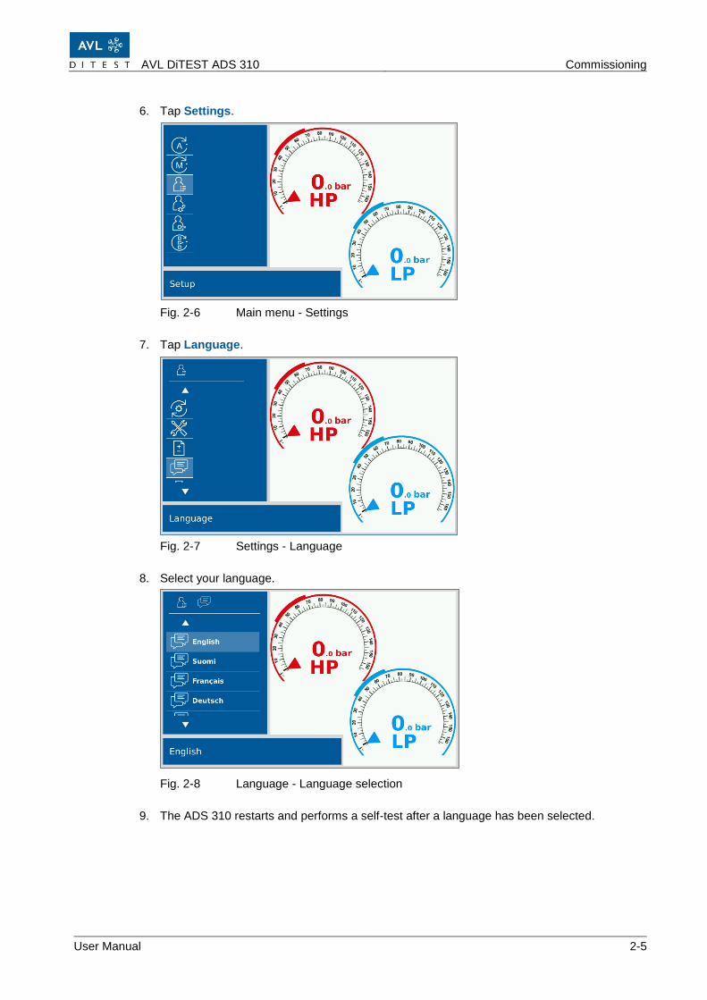
6. Tap Settings.
Fig. 2-6 Main menu - Settings
7. Tap Language.
Fig. 2-7 Settings - Language
8. Select your language.
Fig. 2-8 Language - Language selection
9. The ADS 310 restarts and performs a self-test after a language has been selected.
Commissioning AVL DiTEST ADS 310
2-6 User Manual
2.6 Pressure zeroing
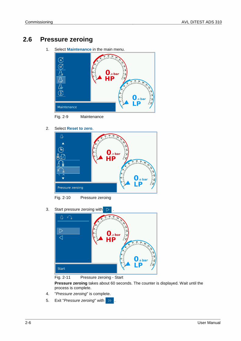
1. Select Maintenance in the main menu.
Fig. 2-9 Maintenance
2. Select Reset to zero.
Fig. 2-10 Pressure zeroing
3. Start pressure zeroing with .
Fig. 2-11 Pressure zeroing - Start
Pressure zeroing takes about 60 seconds. The counter is displayed. Wait until the process is complete.
4. "Pressure zeroing" is complete.
5. Exit "Pressure zeroing" with .
AVL DiTEST ADS 310 Commissioning
User Manual 2-7
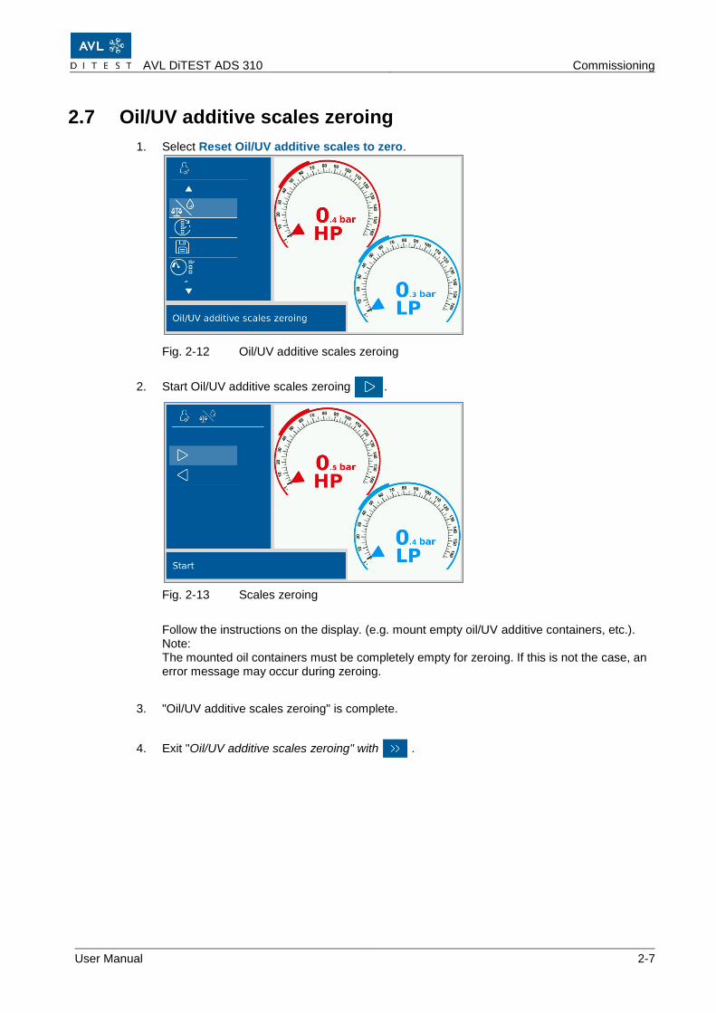
2.7 Oil/UV additive scales zeroing
1. Select Reset Oil/UV additive scales to zero.
Fig. 2-12 Oil/UV additive scales zeroing
2. Start Oil/UV additive scales zeroing .
Fig. 2-13 Scales zeroing
Follow the instructions on the display. (e.g. mount empty oil/UV additive containers, etc.). Note: The mounted oil containers must be completely empty for zeroing. If this is not the case, an error message may occur during zeroing.
3. "Oil/UV additive scales zeroing" is complete.
4. Exit "Oil/UV additive scales zeroing" with .
Commissioning AVL DiTEST ADS 310
2-8 User Manual
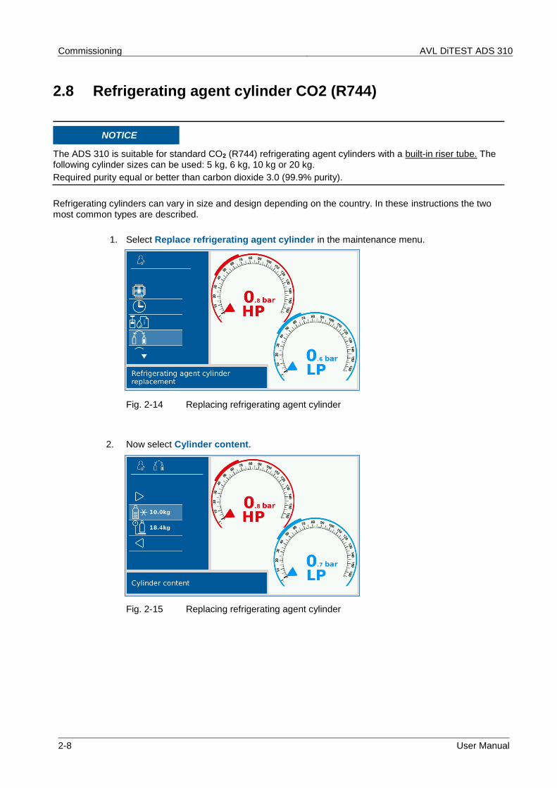
2.8 Refrigerating agent cylinder CO2 (R744)
NOTICE
The ADS 310 is suitable for standard CO2 (R744) refrigerating agent cylinders with a built-in riser tube. The following cylinder sizes can be used: 5 kg, 6 kg, 10 kg or 20 kg.
Required purity equal or better than carbon dioxide 3.0 (99.9% purity).
Refrigerating cylinders can vary in size and design depending on the country. In these instructions the two most common types are described.
1. Select Replace refrigerating agent cylinder in the maintenance menu.
Fig. 2-14 Replacing refrigerating agent cylinder
2. Now select Cylinder content.
Fig. 2-15 Replacing refrigerating agent cylinder
AVL DiTEST ADS 310 Commissioning
User Manual 2-9
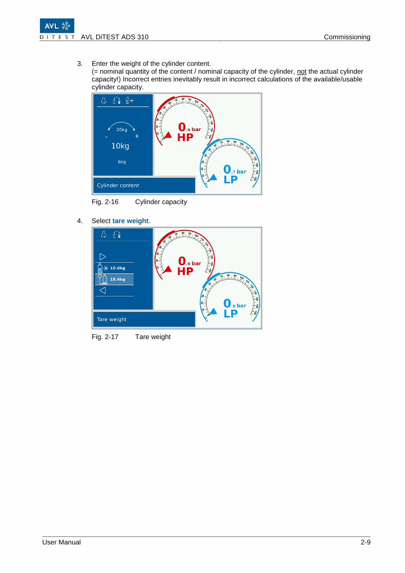
3. Enter the weight of the cylinder content. (= nominal quantity of the content / nominal capacity of the cylinder, not the actual cylinder capacity!) Incorrect entries inevitably result in incorrect calculations of the available/usable cylinder capacity.
Fig. 2-16 Cylinder capacity
4. Select tare weight.
Fig. 2-17 Tare weight
Commissioning AVL DiTEST ADS 310
2-10 User Manual
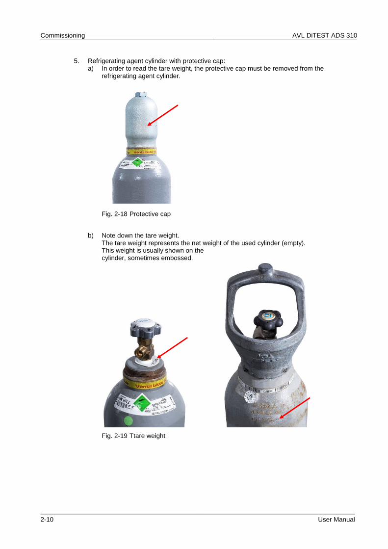
5. Refrigerating agent cylinder with protective cap: a) In order to read the tare weight, the protective cap must be removed from the
refrigerating agent cylinder.
Fig. 2-18 Protective cap
b) Note down the tare weight. The tare weight represents the net weight of the used cylinder (empty). This weight is usually shown on the cylinder, sometimes embossed.
Fig. 2-19 Ttare weight
AVL DiTEST ADS 310 Commissioning
User Manual 2-11
c) Mark the location of the outlet valve on the refrigerating agent cylinder.
Fig. 2-20 Mark
d) Re-attach the protective cap.
Fig. 2-21 Protective cap
Commissioning AVL DiTEST ADS 310
2-12 User Manual
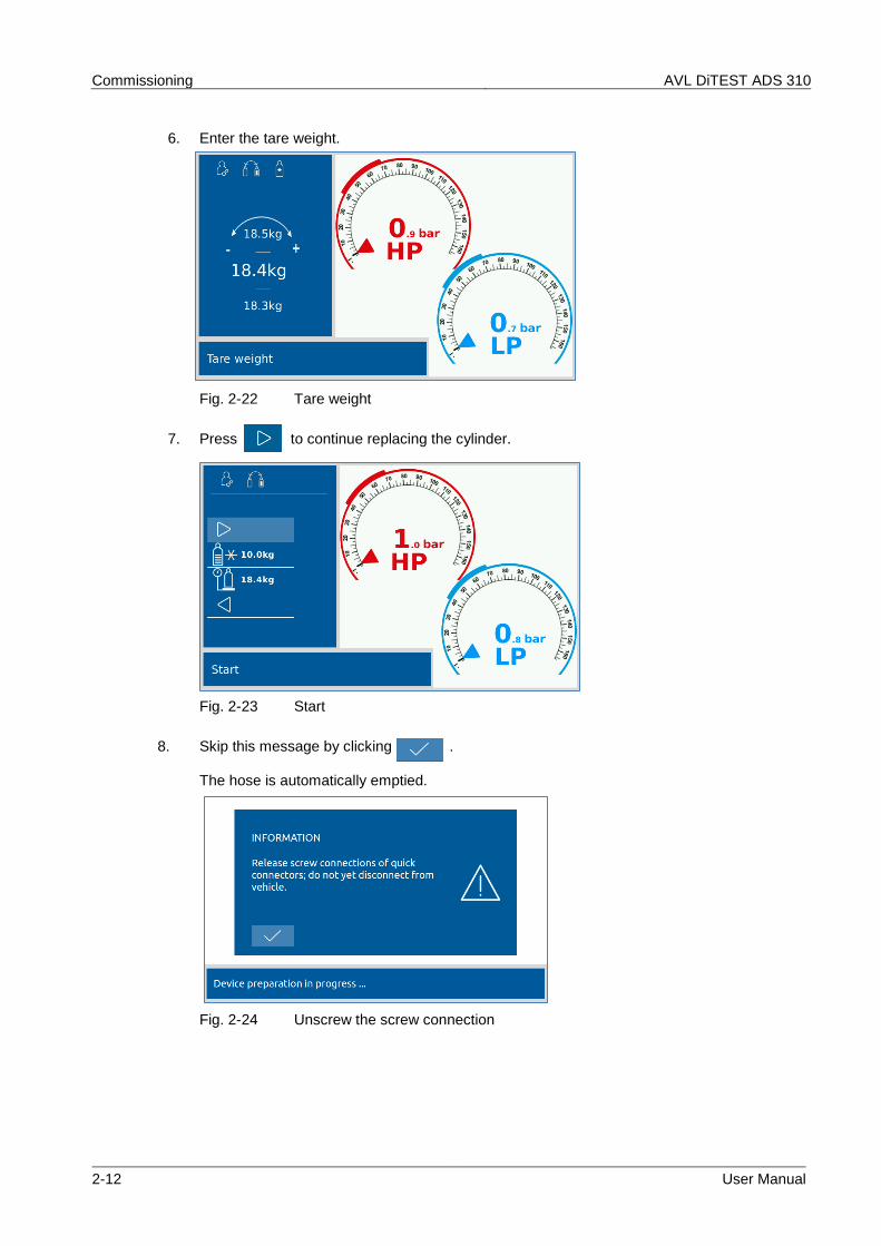
6. Enter the tare weight.
Fig. 2-22 Tare weight
7. Press to continue replacing the cylinder.
Fig. 2-23 Start
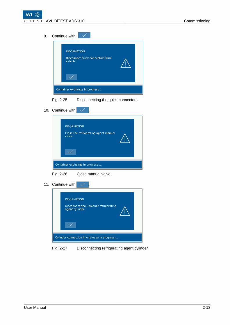
8. Skip this message by clicking . The hose is automatically emptied.
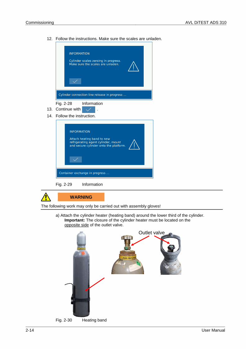
12. Follow the instructions. Make sure the scales are unladen.
Fig. 2-28 Information
13. Continue with .
14. Follow the instruction.
Fig. 2-29 Information
WARNING
The following work may only be carried out with assembly gloves!
a) Attach the cylinder heater (heating band) around the lower third of the cylinder. Important: The closure of the cylinder heater must be located on the opposite side of the outlet valve.
Fig. 2-30 Heating band
Outlet valve
AVL DiTEST ADS 310 Commissioning
User Manual 2-15
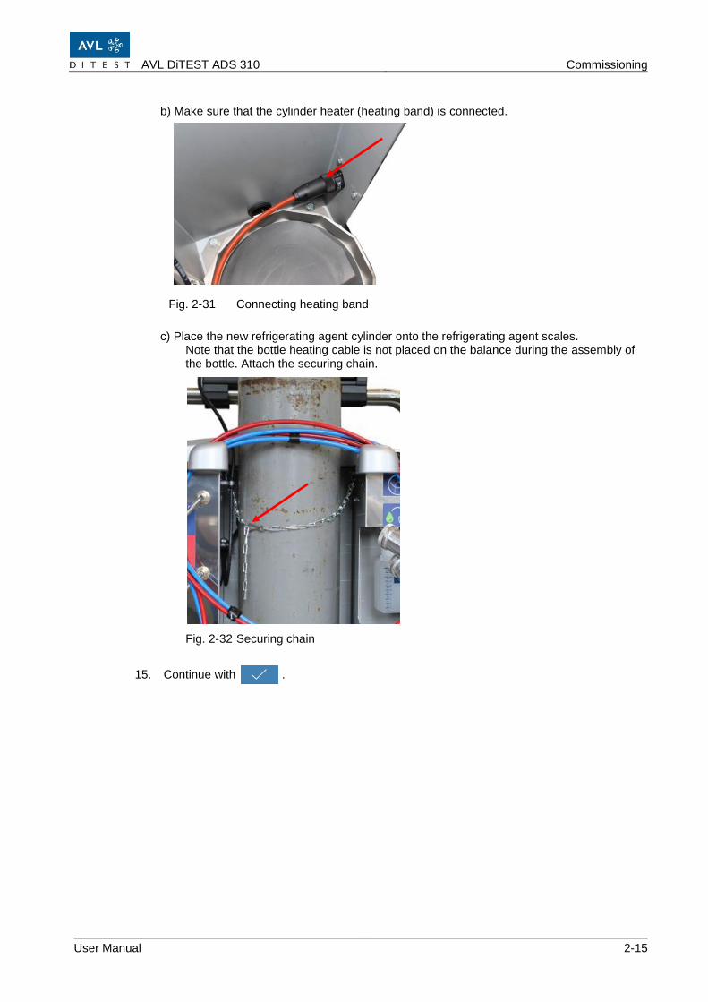
b) Make sure that the cylinder heater (heating band) is connected.
Fig. 2-31 Connecting heating band
c) Place the new refrigerating agent cylinder onto the refrigerating agent scales. Note that the bottle heating cable is not placed on the balance during the assembly of the bottle. Attach the securing chain.
Fig. 2-32 Securing chain
15. Continue with .
Commissioning AVL DiTEST ADS 310
2-16 User Manual
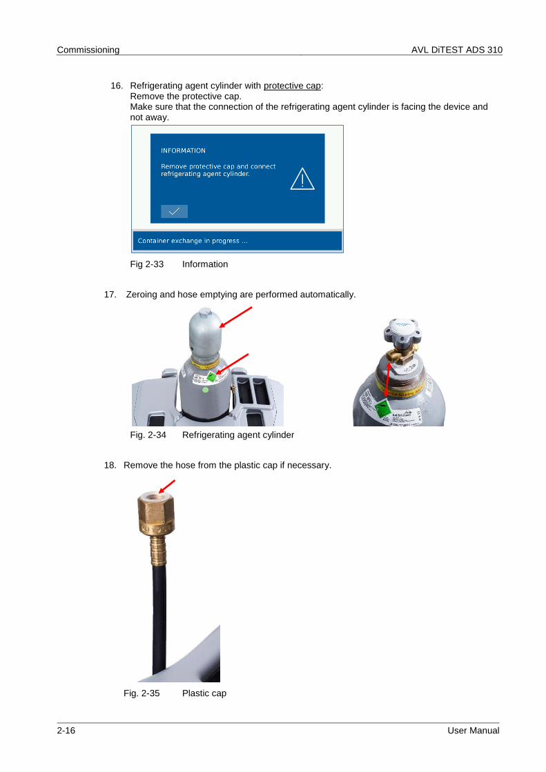
16. Refrigerating agent cylinder with protective cap: Remove the protective cap. Make sure that the connection of the refrigerating agent cylinder is facing the device and not away.
Fig 2-33 Information
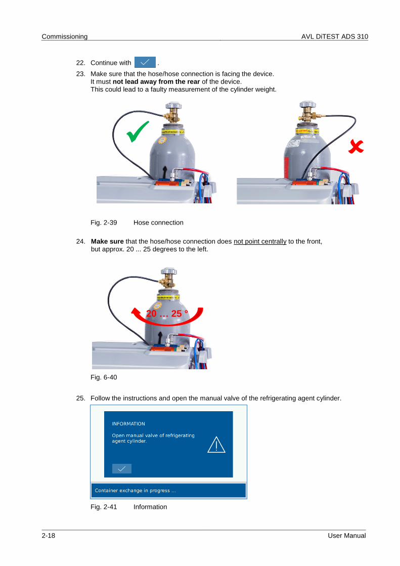
17. Zeroing and hose emptying are performed automatically.
Fig. 2-34 Refrigerating agent cylinder
18. Remove the hose from the plastic cap if necessary.
Fig. 2-35 Plastic cap
AVL DiTEST ADS 310 Commissioning
User Manual 2-17
19. Remove the plastic cap on the outlet valve if necessary.
Fig. 2-36 Refrigerating agent cylinder with Plastic cap
Fig. 2-37 Refrigerating agent cylinder with cylinder adapter
21. Connect the hose to the cylinder adapter. Spanner width: 14 mm Torque: 16 … 18 Nm, max. 20 Nm.
Fig. 2-38 Connect the hose to the cylinder adapter
Commissioning AVL DiTEST ADS 310
2-18 User Manual
22. Continue with .
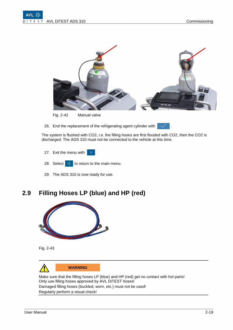
23. Make sure that the hose/hose connection is facing the device. It must not lead away from the rear of the device. This could lead to a faulty measurement of the cylinder weight.
Fig. 2-39 Hose connection
24. Make sure that the hose/hose connection does not point centrally to the front, but approx. 20 ... 25 degrees to the left.
Fig. 6-40
25. Follow the instructions and open the manual valve of the refrigerating agent cylinder.
Fig. 2-41 Information
✓
20 … 25 °
AVL DiTEST ADS 310 Commissioning
User Manual 2-19
Fig. 2-42 Manual valve
26. End the replacement of the refrigerating agent cylinder with . The system is flushed with CO2, i.e. the filling hoses are first flooded with CO2, then the CO2 is discharged. The ADS 310 must not be connected to the vehicle at this time.
27. Exit the menu with .
28. Select to return to the main menu.
29. The ADS 310 is now ready for use.
2.9 Filling Hoses LP (blue) and HP (red)
Fig. 2-43
WARNING
Make sure that the filling hoses LP (blue) and HP (red) get no contact with hot parts! Only use filling hoses approved by AVL DiTEST hoses!
Damaged filling hoses (buckled, worn, etc.) must not be used!
Regularly perform a visual check!
Commissioning AVL DiTEST ADS 310
2-20 User Manual
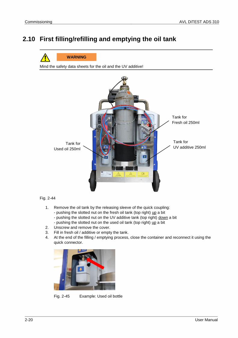
2.10 First filling/refilling and emptying the oil tank
WARNING
Mind the safety data sheets for the oil and the UV additive!
Fig. 2-44
1. Remove the oil tank by the releasing sleeve of the quick coupling:
- pushing the slotted nut on the fresh oil tank (top right) up a bit
- pushing the slotted nut on the UV additive tank (top right) down a bit
- pushing the slotted nut on the used oil tank (top right) up a bit
2. Unscrew and remove the cover.
3. Fill in fresh oil / additive or empty the tank.
4. At the end of the filling / emptying process, close the container and reconnect it using the
quick connector.
Fig. 2-45 Example: Used oil bottle
Tank for
Fresh oil 250ml
Tank for
UV additive 250ml Tank for
Used oil 250ml
AVL DiTEST ADS 310 Commissioning
User Manual 2-21
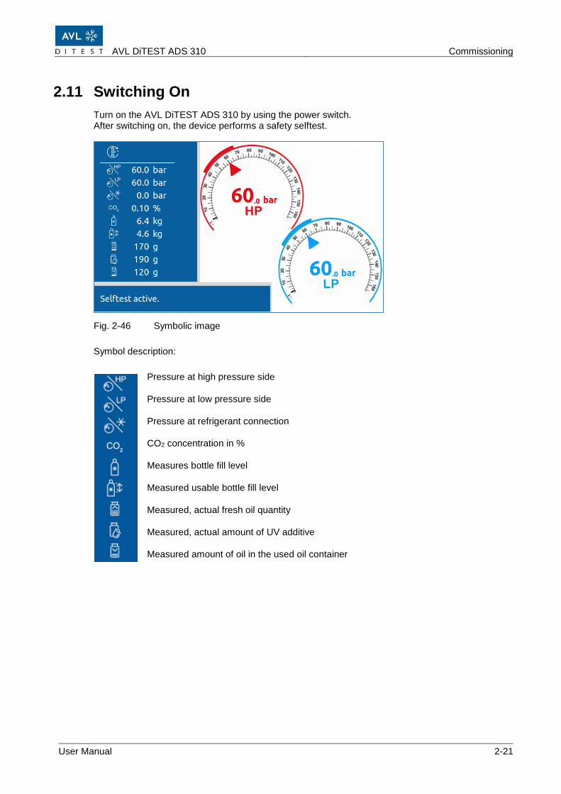
2.11 Switching On
Turn on the AVL DiTEST ADS 310 by using the power switch. After switching on, the device performs a safety selftest.
Fig. 2-46 Symbolic image
Symbol description:
Pressure at high pressure side
Pressure at low pressure side
Pressure at refrigerant connection
CO2 concentration in %
Measures bottle fill level
Measured usable bottle fill level
Measured, actual fresh oil quantity
Measured, actual amount of UV additive
Measured amount of oil in the used oil container
Commissioning AVL DiTEST ADS 310
2-22 User Manual
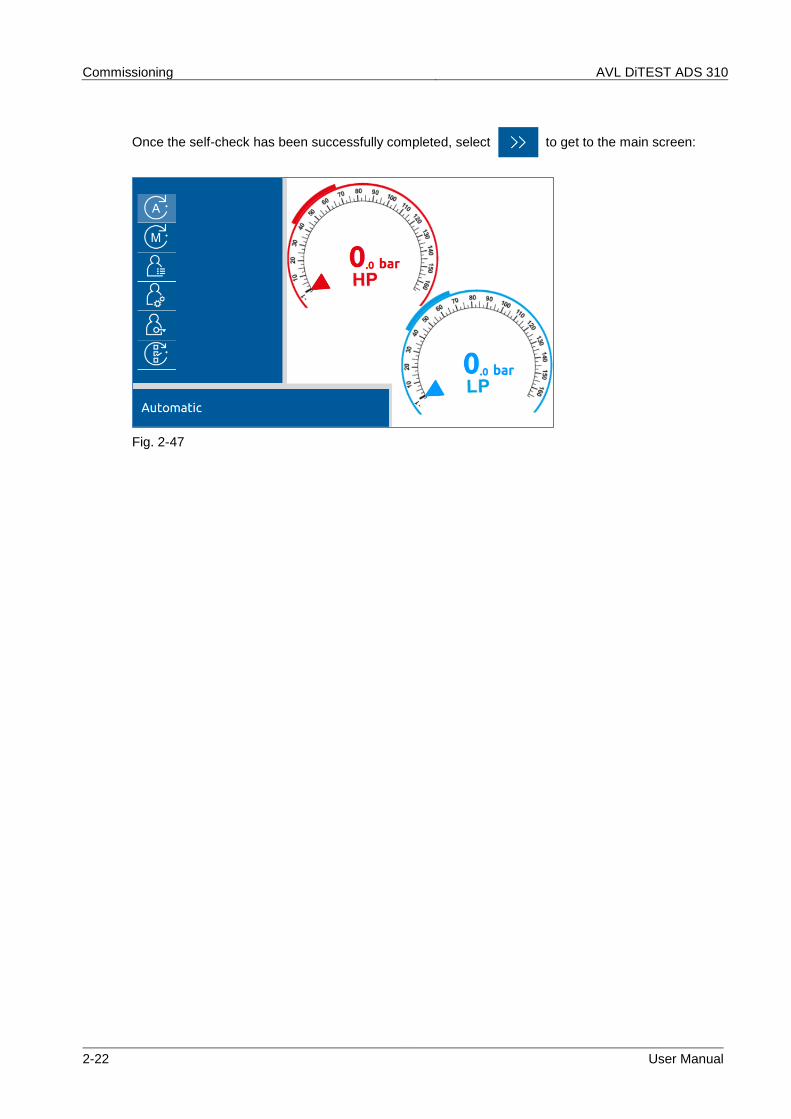
Once the self-check has been successfully completed, select to get to the main screen:
Fig. 2-47
AVL DiTEST ADS 310 Automated cycle
User Manual 3-1
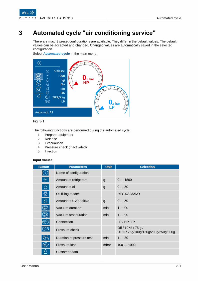
3 Automated cycle "air conditioning service"
There are max. 3 preset configurations are available. They differ in the default values. The default values can be accepted and changed. Changed values are automatically saved in the selected configuration.
Select Automated cycle in the main menu.
Fig. 3-1
The following functions are performed during the automated cycle:
NO: No oil is introduced into the air conditioning system of the vehicle. The set oil quantity is ignored
ABS: The set oil quantity is entered into the air conditioning system of the vehicle brought in.
REC+: Depending on the quantity of recovered oil, this amount will be plus Of the adjusted oil quantity into the air conditioning system of the vehicle. Eg: Recovered oil quantity = 8 grams of waste oil, Adjusted oil quantity = 10 grams, -> 18 grams of oil are added to the vehicle
Check your entries and confirm entry with . The automated cycle starts.
Follow the instructions on the screen.
The functions Prepare equipment, release, evacuation pressure check (if activadet) and injection are carried out automatically. Also observe the color display of the multi-function rotary wheel, see chap
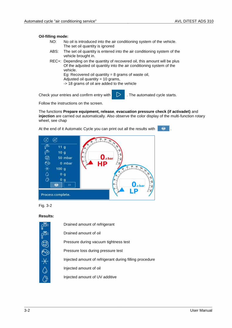
At the end of it Automatic Cycle you can print out all the results with .
Fig. 3-2
Results:
Drained amount of refrigerant
Drained amount of oil
Pressure during vacuum tightness test
Pressure loss during pressure test
Injected amount of refrigerant during filling procedure
Injected amount of oil
Injected amount of UV additive
AVL DiTEST ADS 310 Manual cycle
User Manual 4-1
4 Manual cycle
NOTE
Do not connect the quick couplings to the air-conditioning system until the AVL DiTEST ADS 310 prompts you to do so.
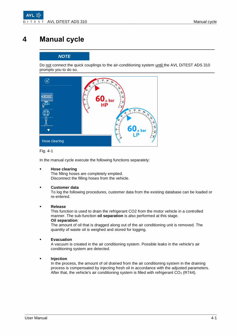
Fig. 4-1
In the manual cycle execute the following functions separately:
▪ Hose clearing The filling hoses are completely emptied. Disconnect the filling hoses from the vehicle.
▪ Customer data
To log the following procedures, customer data from the existing database can be loaded or re-entered.
▪ Release This function is used to drain the refrigerant CO2 from the motor vehicle in a controlled manner. The sub-function oil separation is also performed at this stage. Oil separation: The amount of oil that is dragged along out of the air conditioning unit is removed. The quantity of waste oil is weighed and stored for logging.
▪ Evacuation A vacuum is created in the air conditioning system. Possible leaks in the vehicle's air conditioning system are detected.
▪ Injection In the process, the amount of oil drained from the air conditioning system in the draining process is compensated by injecting fresh oil in accordance with the adjusted parameters. After that, the vehicle's air conditioning system is filled with refrigerant CO2 (R744).
Manual cycle AVL DiTEST ADS 310
4-2 User Manual
▪ Pressure check This function is used to fill the vehicle air conditioning unit with a set refrigerant quantity of 70 to 300 grams. A pressure loss over the selected time period is determined. A possible leak in the climate system of the vehicle is thus detected.
▪ HD/ND Pressure check
This function is used to measure and display the pressure of the vehicle air conditioning system during operation.
▪ External Pressure check
With this function, the vehicle air conditioning system is acted upon by a forming gas / nitrogen bottle at a pressure of 90 to 100 bar. A pressure loss over the selected time period is determined.
AVL DiTEST ADS 310 Manual cycle
User Manual 4-3
4.1 Emptying clearing
In the main menu, select Manual mode│Hose clearing.
The “hose emptying” function allows you to entirely empty the filling hoses.
Hoses should not be emptied when the vehicle is connected.
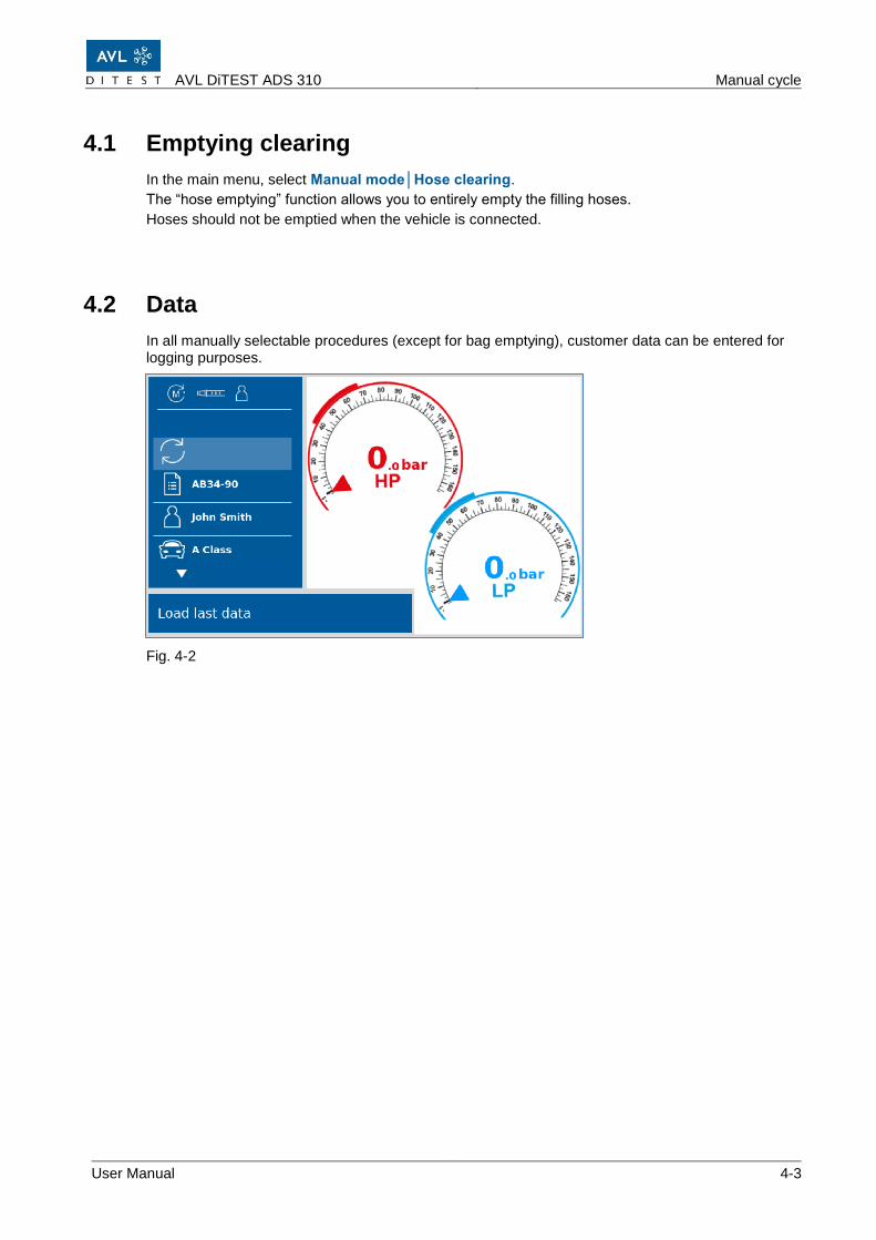
4.2 Data
In all manually selectable procedures (except for bag emptying), customer data can be entered for logging purposes.
Fig. 4-2
Manual cycle AVL DiTEST ADS 310
4-4 User Manual
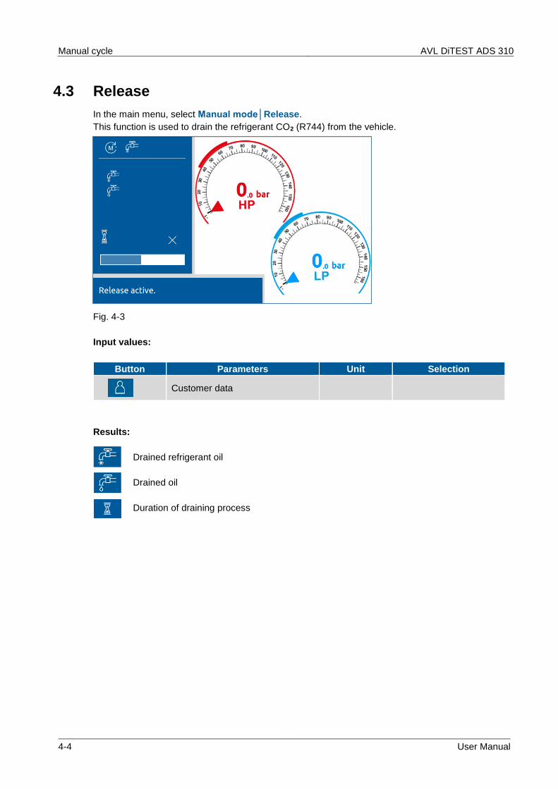
4.3 Release
In the main menu, select Manual mode│Release.
This function is used to drain the refrigerant CO2 (R744) from the vehicle.
Fig. 4-3
Input values:
Button Parameters Unit Selection
Customer data
Results:
Drained refrigerant oil
Drained oil
Duration of draining process
AVL DiTEST ADS 310 Manual cycle
User Manual 4-5
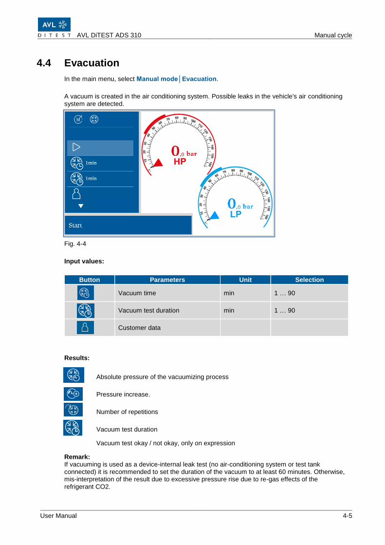
4.4 Evacuation
In the main menu, select Manual mode│Evacuation.
A vacuum is created in the air conditioning system. Possible leaks in the vehicle's air conditioning system are detected.
Fig. 4-4
Input values:
Button Parameters Unit Selection
Vacuum time min 1 … 90
Vacuum test duration min 1 … 90
Customer data
Results:
Absolute pressure of the vacuumizing process
Pressure increase.
Number of repetitions
Vacuum test duration
Vacuum test okay / not okay, only on expression
Remark: If vacuuming is used as a device-internal leak test (no air-conditioning system or test tank connected) it is recommended to set the duration of the vacuum to at least 60 minutes. Otherwise, mis-interpretation of the result due to excessive pressure rise due to re-gas effects of the refrigerant CO2.
Manual cycle AVL DiTEST ADS 310
4-6 User Manual
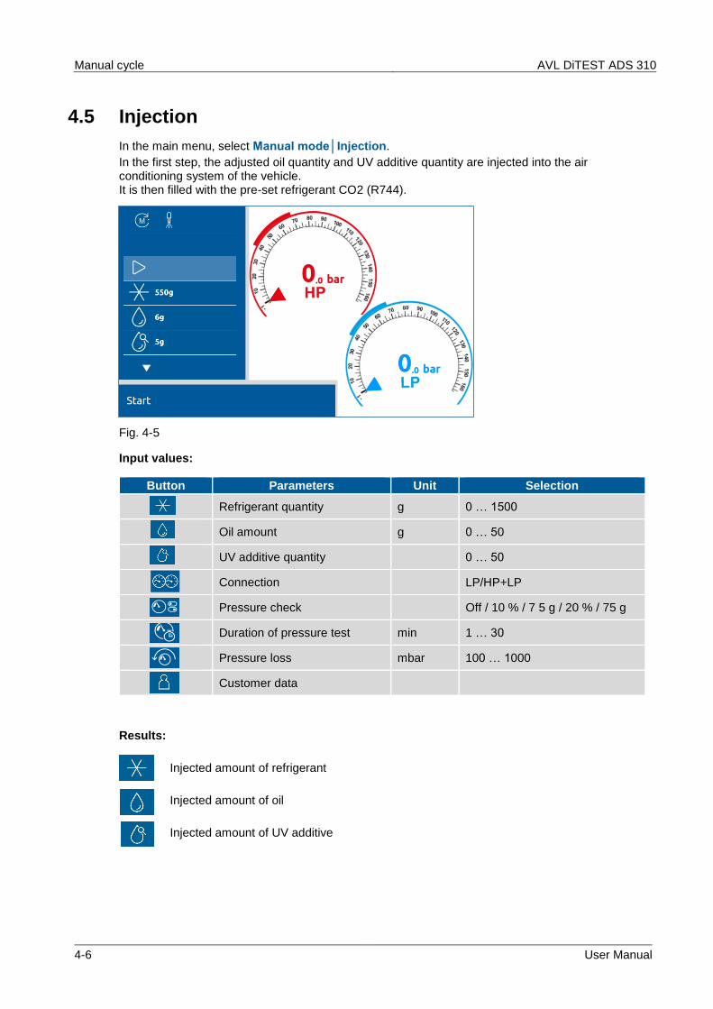
4.5 Injection
In the main menu, select Manual mode│Injection.
In the first step, the adjusted oil quantity and UV additive quantity are injected into the air conditioning system of the vehicle. It is then filled with the pre-set refrigerant CO2 (R744).
Fig. 4-5
Input values:
Button Parameters Unit Selection
Refrigerant quantity g 0 … 1500
Oil amount g 0 … 50
UV additive quantity 0 … 50
Connection LP/HP+LP
Pressure check Off / 10 % / 7 5 g / 20 % / 75 g
Duration of pressure test min 1 … 30
Pressure loss mbar 100 … 1000
Customer data
Results:
Injected amount of refrigerant
Injected amount of oil
Injected amount of UV additive
AVL DiTEST ADS 310 Manual cycle
User Manual 4-7
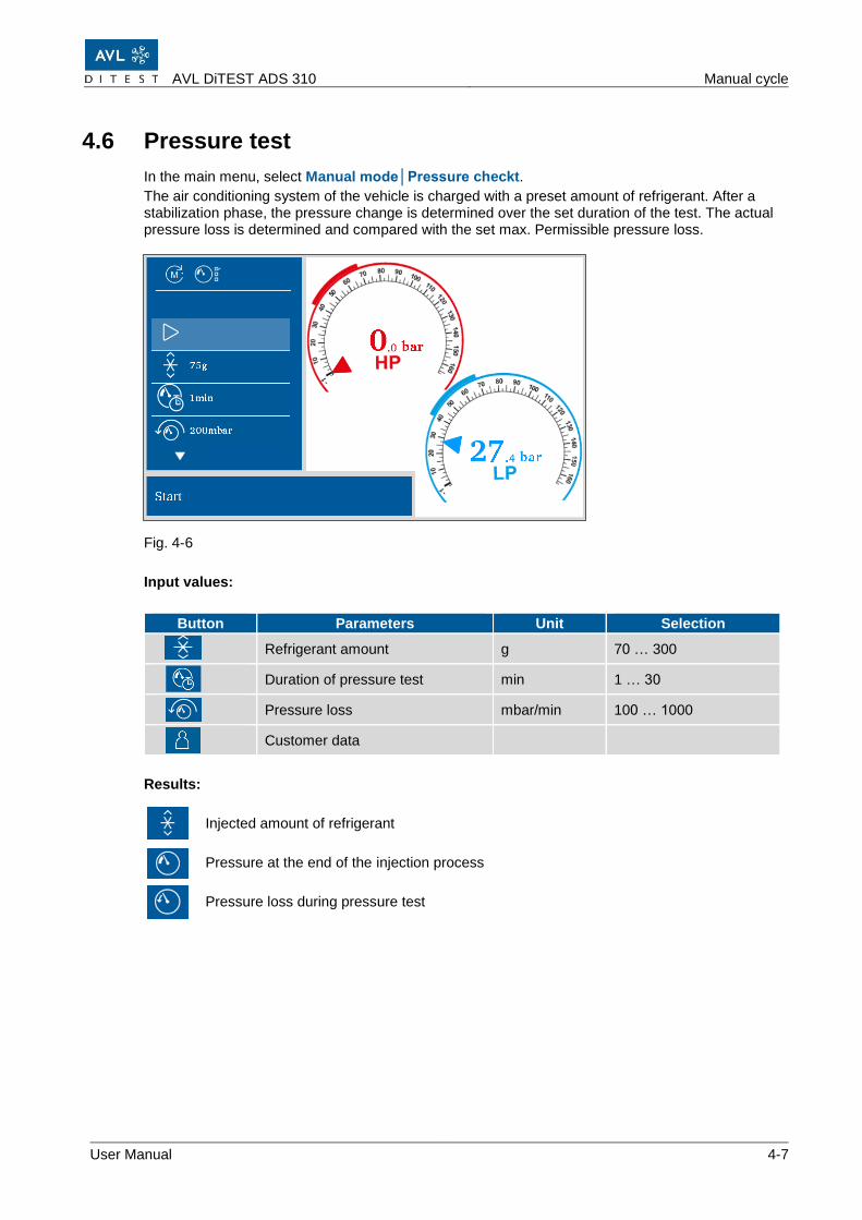
4.6 Pressure test
In the main menu, select Manual mode│Pressure checkt.
The air conditioning system of the vehicle is charged with a preset amount of refrigerant. After a stabilization phase, the pressure change is determined over the set duration of the test. The actual pressure loss is determined and compared with the set max. Permissible pressure loss.
Fig. 4-6
Input values:
Button Parameters Unit Selection
Refrigerant amount g 70 … 300
Duration of pressure test min 1 … 30
Pressure loss mbar/min 100 … 1000
Customer data
Results:
Injected amount of refrigerant
Pressure at the end of the injection process
Pressure loss during pressure test
Manual cycle AVL DiTEST ADS 310
4-8 User Manual
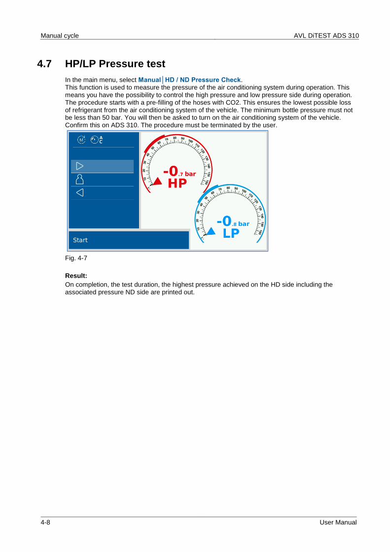
4.7 HP/LP Pressure test
In the main menu, select Manual│HD / ND Pressure Check. This function is used to measure the pressure of the air conditioning system during operation. This means you have the possibility to control the high pressure and low pressure side during operation. The procedure starts with a pre-filling of the hoses with CO2. This ensures the lowest possible loss of refrigerant from the air conditioning system of the vehicle. The minimum bottle pressure must not be less than 50 bar. You will then be asked to turn on the air conditioning system of the vehicle. Confirm this on ADS 310. The procedure must be terminated by the user.
Fig. 4-7
Result:
On completion, the test duration, the highest pressure achieved on the HD side including the associated pressure ND side are printed out.
AVL DiTEST ADS 310 Manual cycle
User Manual 4-9
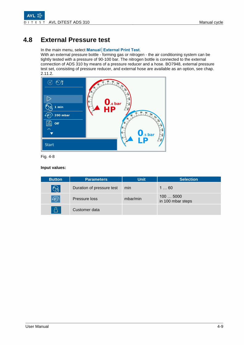
4.8 External Pressure test
In the main menu, select Manual│External Print Test. With an external pressure bottle - forming gas or nitrogen - the air conditioning system can be tightly tested with a pressure of 90-100 bar. The nitrogen bottle is connected to the external connection of ADS 310 by means of a pressure reducer and a hose. BO7948, external pressure test set, consisting of pressure reducer, and external hose are available as an option, see chap. 2.11.2.
Fig. 4-8
Input values:
Button Parameters Unit Selection
Duration of pressure test min 1 … 60
Pressure loss mbar/min
100 … 5000 in 100 mbar steps
Customer data
Manual cycle AVL DiTEST ADS 310
4-10 User Manual
AVL DiTEST ADS 310 Manual cycle
User Manual 5-1
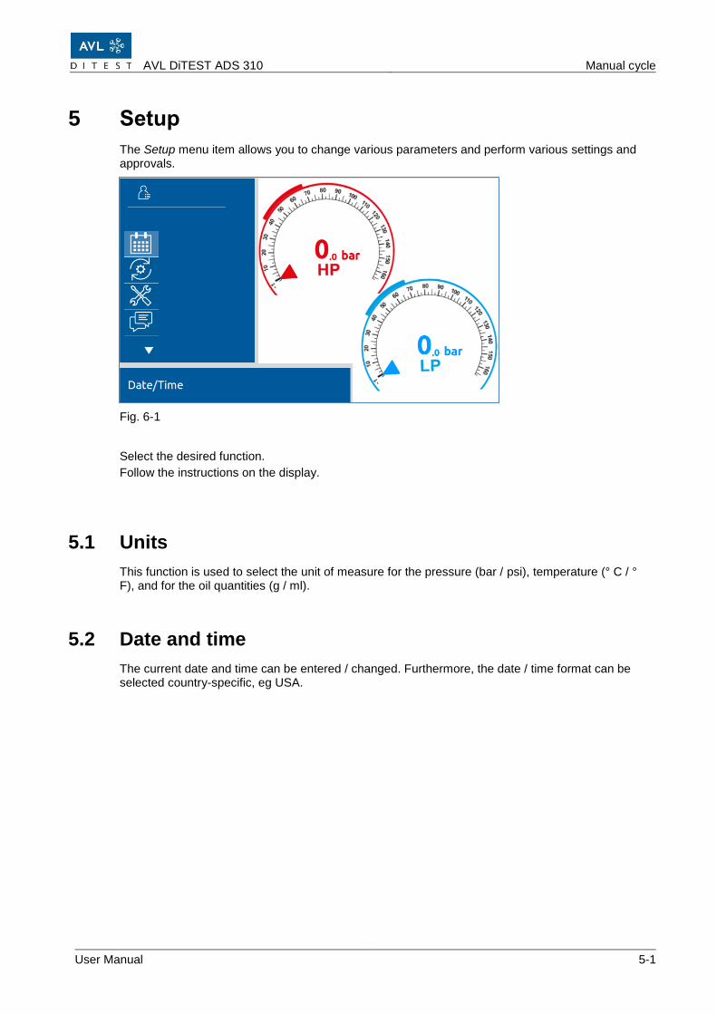
5 Setup
The Setup menu item allows you to change various parameters and perform various settings and approvals.
Fig. 6-1
Select the desired function.
Follow the instructions on the display.
5.1 Units
This function is used to select the unit of measure for the pressure (bar / psi), temperature (° C / ° F), and for the oil quantities (g / ml).
5.2 Date and time
The current date and time can be entered / changed. Furthermore, the date / time format can be selected country-specific, eg USA.
Setup AVL DiTEST ADS 310
5-2 User Manual
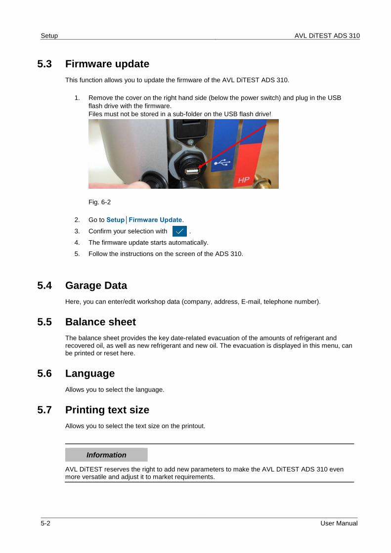
5.3 Firmware update
This function allows you to update the firmware of the AVL DiTEST ADS 310.
1. Remove the cover on the right hand side (below the power switch) and plug in the USB
flash drive with the firmware.
Files must not be stored in a sub-folder on the USB flash drive!
Fig. 6-2
2. Go to Setup│Firmware Update.
3. Confirm your selection with .
4. The firmware update starts automatically.
5. Follow the instructions on the screen of the ADS 310.
5.4 Garage Data
Here, you can enter/edit workshop data (company, address, E-mail, telephone number).
5.5 Balance sheet
The balance sheet provides the key date-related evacuation of the amounts of refrigerant and recovered oil, as well as new refrigerant and new oil. The evacuation is displayed in this menu, can be printed or reset here.
5.6 Language
Allows you to select the language.
5.7 Printing text size
Allows you to select the text size on the printout.
Information
AVL DiTEST reserves the right to add new parameters to make the AVL DiTEST ADS 310 even more versatile and adjust it to market requirements.
AVL DiTEST ADS 310 Maintenance
User Manual 6-1
6 Maintenance
6.1 Maintenance Plan
To guarantee its trouble-free function, the AVL DiTEST ADS 310 must be serviced at regular intervals. The maintenance work carried out needs to be recorded in the inspection log book.
If required, for instance in case of problems, additional maintenance work can be carried out or information can be requested.
Component / assembly / function Interval Description
Regular maintenance
Changing the vacuum pump oil Every 500 operating hours or at least once a year
Check refrigerant bottle CO2 (R744) Weekly Chapter 6.2.3
Check bottle adapter Weekly Chapter 6.2.4
Check ND and HD hoses Weekly Chapter 6.2.5
Check quick couplings Weekly Chapter 6.2.6
Check bottle heating (heating tape) in switched off state
Daily Chapter 6.2.7
Device check Weekly Chapter 6.2.8
Irregular maintenance (if required)
Bottle exchange As required Chapter 6.3.1
Pressure Zero As required Chapter 6.3.2
Oil/UV additive weight zero As required Chapter 6.3.3
Save Logs As required Chapter 6.3.4
Printer Change printer paper As required Chapter 6.3.5
Fuses Fuse replacement As required Chapter 6.3.6
Additional maintenance information
System info --- Chapter 6.4.1
Operating hours --- Chapter 6.4.2
Replace seals --- Chapter
WARNING
Danger to life from electric current
Prior to opening the AVL DiTEST ADS 310, make sure it has been disconnected from the power supply!
Maintenance AVL DiTEST ADS 310
6-2 User Manual
WARNING
Do not alter the AVL DiTEST ADS 310 in any way not described in this chapter!
WARNING
Use original AVL DiTEST spare parts only!
AVL DiTEST ADS 310 Maintenance
User Manual 6-3
6.2 Regular maintenance
6.2.1 Changing the vacuum pump oil
Once the vacuum pump has reached 500 operating hours, or at least once a year, the vacuum pump oil needs to be changed. The AVL DiTEST ADS 310 points out the required vacuum pump oil change to you.
1. Select Maintenance│Vacuum pump oil.
2. The following is being displayed: - Time since last oil regeneration - Remaining time for oil regeneration - Time since last oil change - Remaining time for oil change - Start the regeneration of the vacuum pump oil - Reset counter for vacuum pump oil (for vacuum pump oil exchange)
3. Switch off the ADS 310 and additionally disconnect the mains plug!
4. Switch off the AVL DiTEST ADS 310 and additionally disconnect the mains plug!
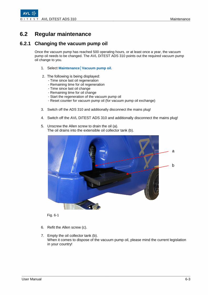
5. Unscrew the Allen screw to drain the oil (a). The oil drains into the extensible oil collector tank (b). Fig. 6-1
6. Refit the Allen screw (c).
7. Empty the oil collector tank (b). When it comes to dispose of the vacuum pump oil, please mind the current legislation in your country!
b
a
Maintenance AVL DiTEST ADS 310
6-4 User Manual
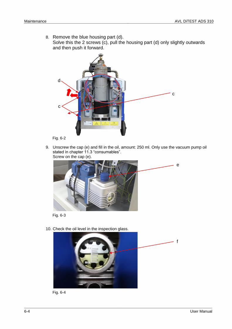
8. Remove the blue housing part (d). Solve this the 2 screws (c), pull the housing part (d) only slightly outwards and then push it forward. Fig. 6-2
9. Unscrew the cap (e) and fill in the oil, amount: 250 ml. Only use the vacuum pump oil stated in chapter 11.3 “consumables”. Screw on the cap (e). Fig. 6-3
10. Check the oil level in the inspection glass.
Fig. 6-4
c
e
f
c
d
AVL DiTEST ADS 310 Maintenance
User Manual 6-5
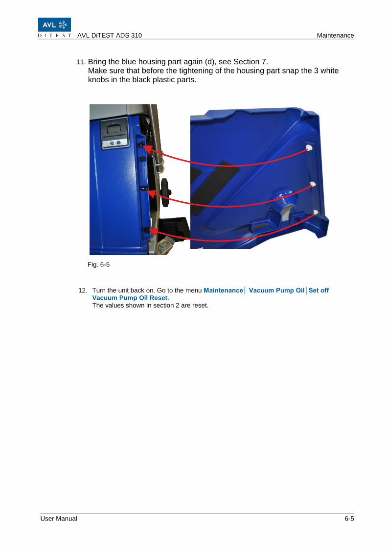
11. Bring the blue housing part again (d), see Section 7. Make sure that before the tightening of the housing part snap the 3 white knobs in the black plastic parts.
Fig. 6-5
12. Turn the unit back on. Go to the menu Maintenance│ Vacuum Pump Oil│Set off Vacuum Pump Oil Reset. The values shown in section 2 are reset.
Maintenance AVL DiTEST ADS 310
6-6 User Manual
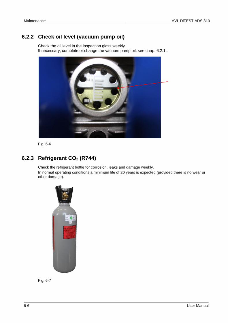
6.2.2 Check oil level (vacuum pump oil)
Check the oil level in the inspection glass weekly. If necessary, complete or change the vacuum pump oil, see chap. 6.2.1 .
Fig. 6-6
6.2.3 Refrigerant CO2 (R744)
Check the refrigerant bottle for corrosion, leaks and damage weekly.
In normal operating conditions a minimum life of 20 years is expected (provided there is no wear or other damage).
Fig. 6-7
AVL DiTEST ADS 310 Maintenance
User Manual 6-7
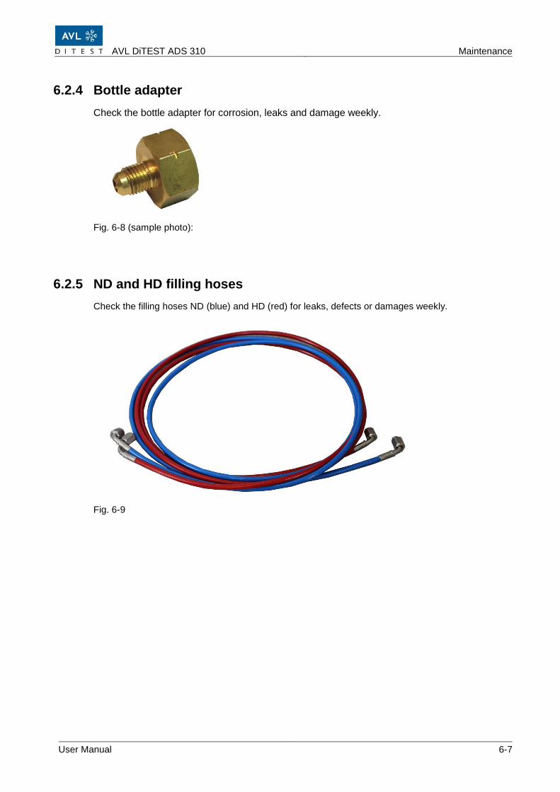
6.2.4 Bottle adapter
Check the bottle adapter for corrosion, leaks and damage weekly.
Fig. 6-8 (sample photo):
6.2.5 ND and HD filling hoses
Check the filling hoses ND (blue) and HD (red) for leaks, defects or damages weekly.
Fig. 6-9
Maintenance AVL DiTEST ADS 310
6-8 User Manual
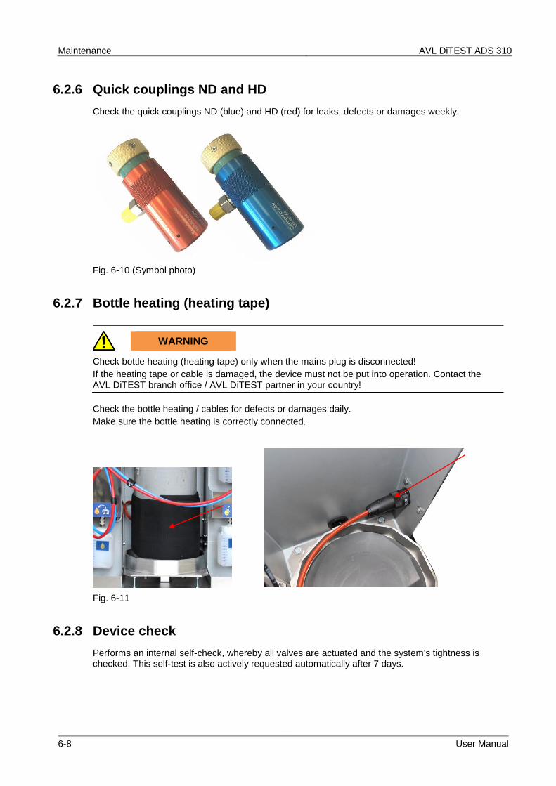
6.2.6 Quick couplings ND and HD
Check the quick couplings ND (blue) and HD (red) for leaks, defects or damages weekly.
Fig. 6-10 (Symbol photo)
6.2.7 Bottle heating (heating tape)
WARNING
Check bottle heating (heating tape) only when the mains plug is disconnected!
If the heating tape or cable is damaged, the device must not be put into operation. Contact the AVL DiTEST branch office / AVL DiTEST partner in your country!
Check the bottle heating / cables for defects or damages daily.
Make sure the bottle heating is correctly connected.
Fig. 6-11
6.2.8 Device check
Performs an internal self-check, whereby all valves are actuated and the system's tightness is checked. This self-test is also actively requested automatically after 7 days.
AVL DiTEST ADS 310 Maintenance
User Manual 6-9
6.3 Irregular maintenance, if required
6.3.1 Replacement refrigerant bottle CO2 (R744)
Proceed as following:
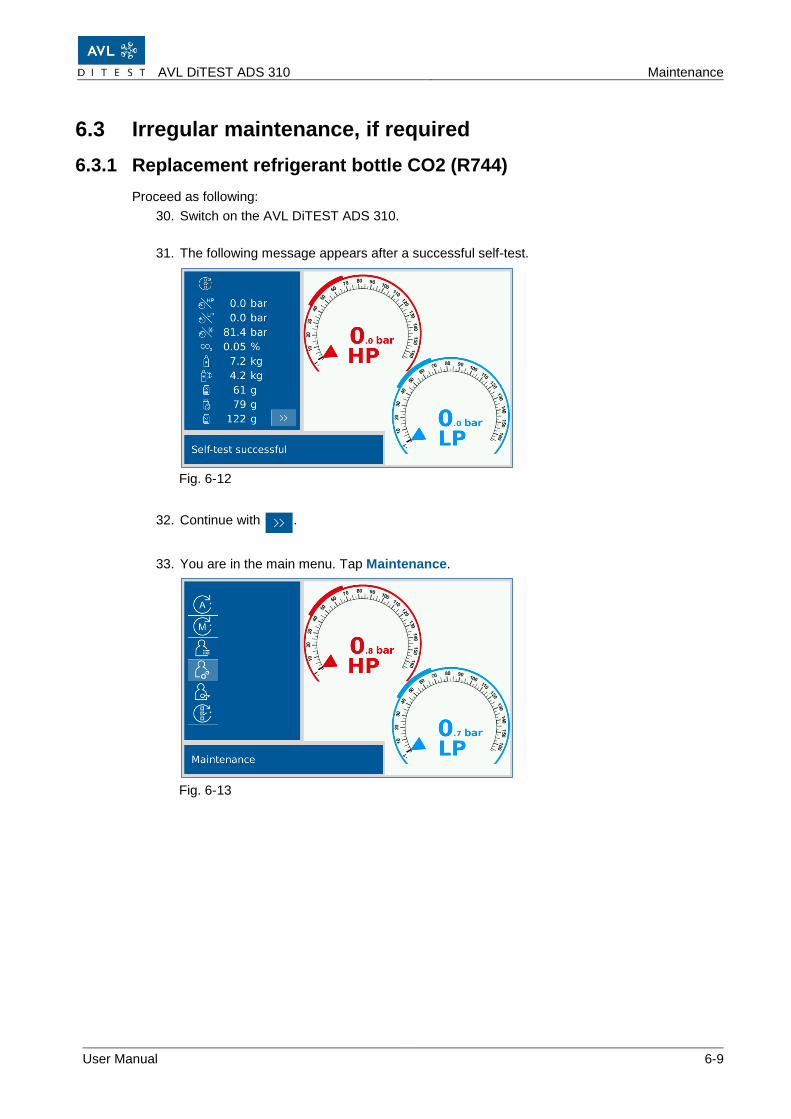
30. Switch on the AVL DiTEST ADS 310.
31. The following message appears after a successful self-test.
Fig. 6-12
32. Continue with .
33. You are in the main menu. Tap Maintenance.
Fig. 6-13
Maintenance AVL DiTEST ADS 310
6-10 User Manual
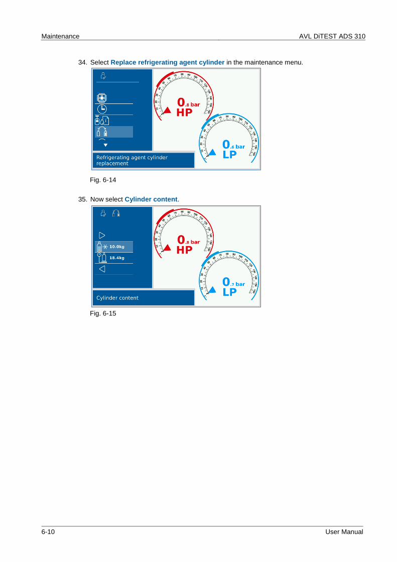
34. Select Replace refrigerating agent cylinder in the maintenance menu.
Fig. 6-14
35. Now select Cylinder content.
Fig. 6-15
AVL DiTEST ADS 310 Maintenance
User Manual 6-11
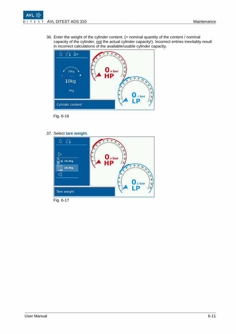
36. Enter the weight of the cylinder content. (= nominal quantity of the content / nominal capacity of the cylinder, not the actual cylinder capacity!). Incorrect entries inevitably result in incorrect calculations of the available/usable cylinder capacity.
Fig. 6-16
37. Select tare weight.
Fig. 6-17
Maintenance AVL DiTEST ADS 310
6-12 User Manual
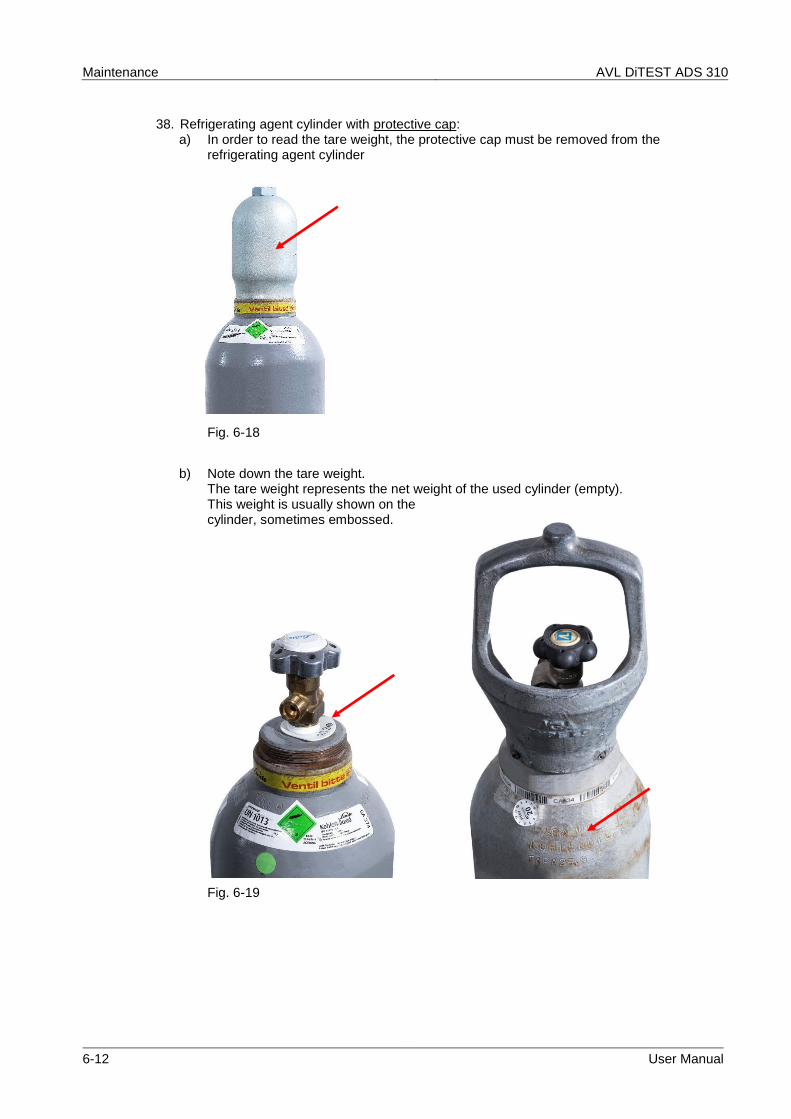
38. Refrigerating agent cylinder with protective cap: a) In order to read the tare weight, the protective cap must be removed from the
refrigerating agent cylinder
Fig. 6-18
b) Note down the tare weight. The tare weight represents the net weight of the used cylinder (empty). This weight is usually shown on the cylinder, sometimes embossed.
Fig. 6-19
AVL DiTEST ADS 310 Maintenance
User Manual 6-13
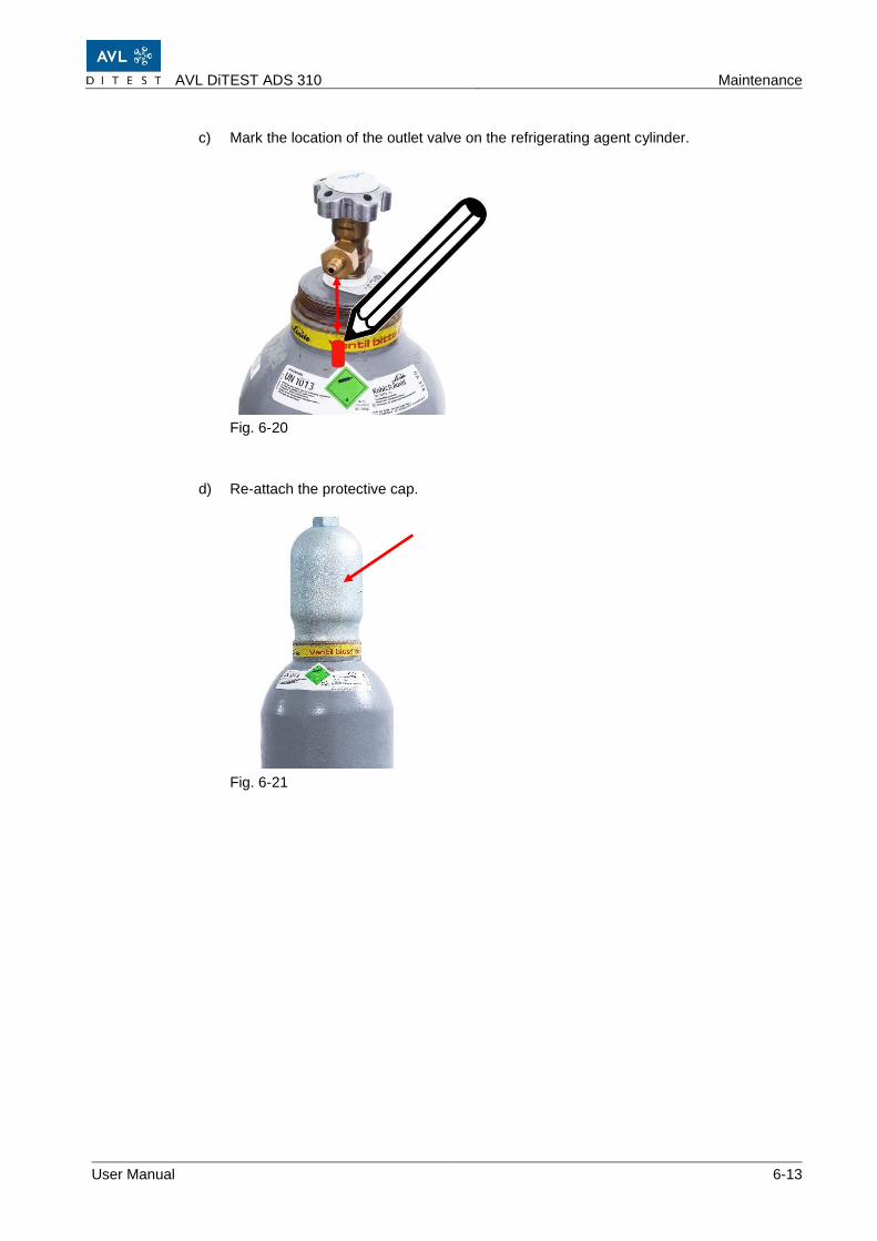
c) Mark the location of the outlet valve on the refrigerating agent cylinder.
Fig. 6-20
d) Re-attach the protective cap.
Fig. 6-21
Maintenance AVL DiTEST ADS 310
6-14 User Manual
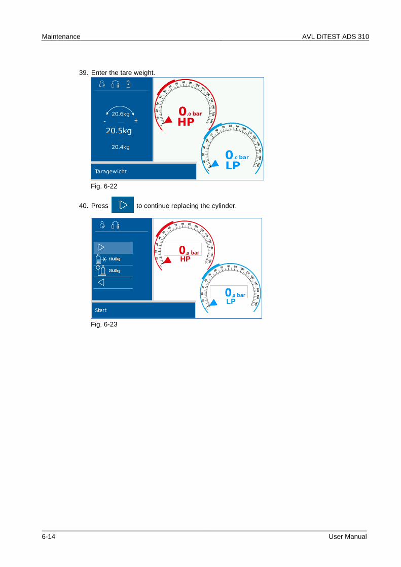
39. Enter the tare weight.
Fig. 6-22
40. Press to continue replacing the cylinder.
Fig. 6-23
AVL DiTEST ADS 310 Maintenance
User Manual 6-15
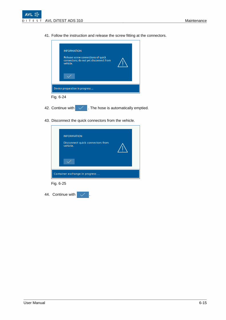
41. Follow the instruction and release the screw fitting at the connectors.
Fig. 6-24
42. Continue with . The hose is automatically emptied.
43. Disconnect the quick connectors from the vehicle.
Fig. 6-25
44. Continue with .
Maintenance AVL DiTEST ADS 310
6-16 User Manual
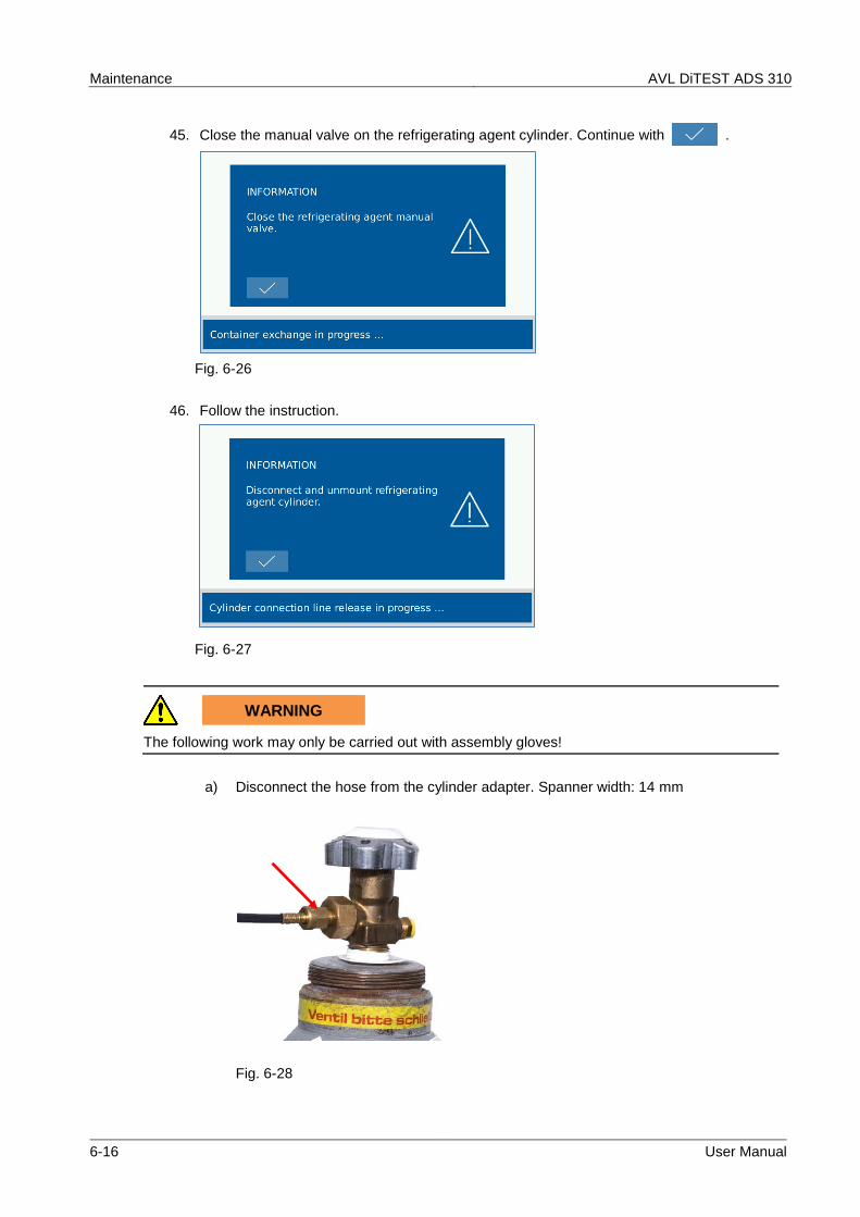
45. Close the manual valve on the refrigerating agent cylinder. Continue with .
Fig. 6-26
46. Follow the instruction.
Fig. 6-27
WARNING
The following work may only be carried out with assembly gloves!
a) Disconnect the hose from the cylinder adapter. Spanner width: 14 mm
Fig. 6-28
AVL DiTEST ADS 310 Maintenance
User Manual 6-17
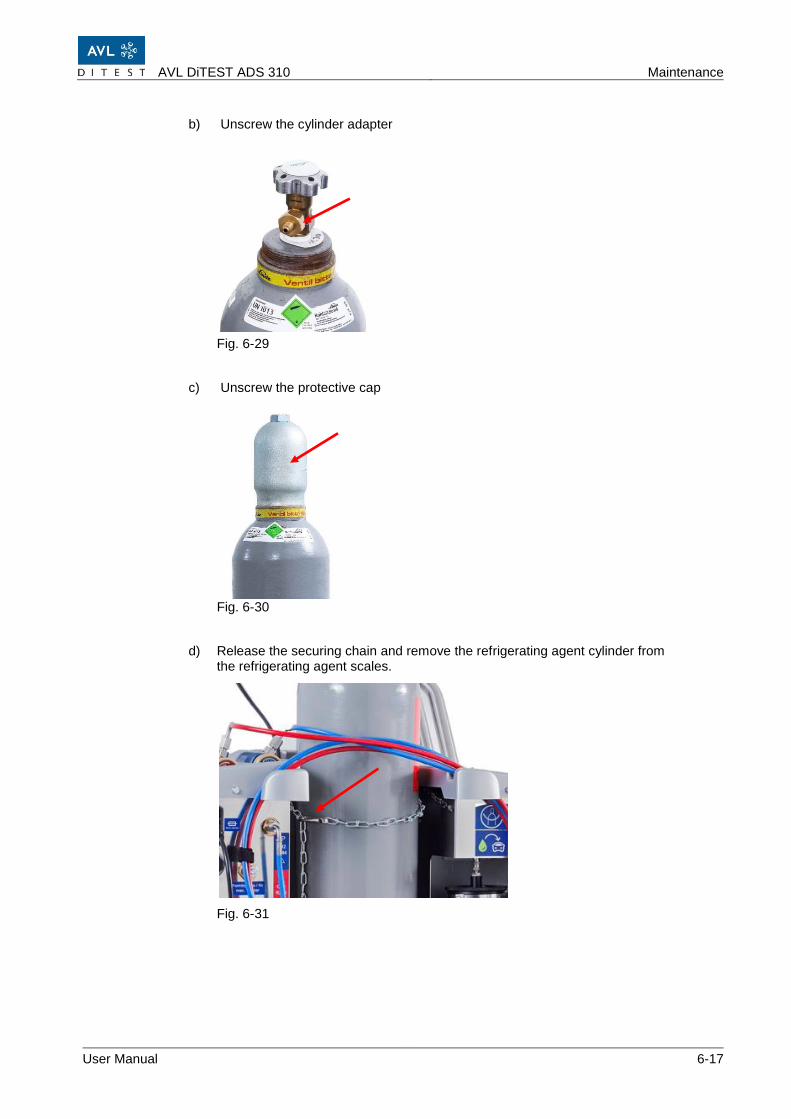
b) Unscrew the cylinder adapter
Fig. 6-29
c) Unscrew the protective cap
Fig. 6-30
d) Release the securing chain and remove the refrigerating agent cylinder from the refrigerating agent scales.
Fig. 6-31
Maintenance AVL DiTEST ADS 310
6-18 User Manual
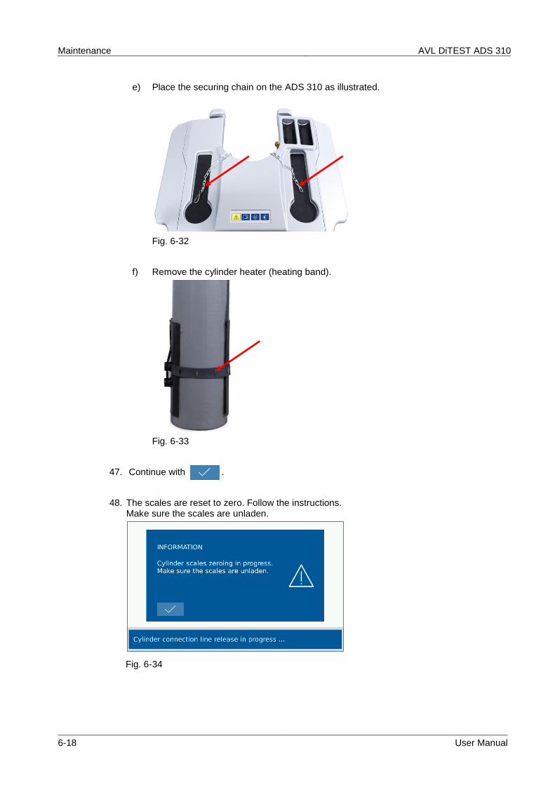
e) Place the securing chain on the ADS 310 as illustrated.
Fig. 6-32
f) Remove the cylinder heater (heating band).
Fig. 6-33
47. Continue with .
48. The scales are reset to zero. Follow the instructions. Make sure the scales are unladen.
Fig. 6-34
AVL DiTEST ADS 310 Maintenance
User Manual 6-19
49. Continue with .
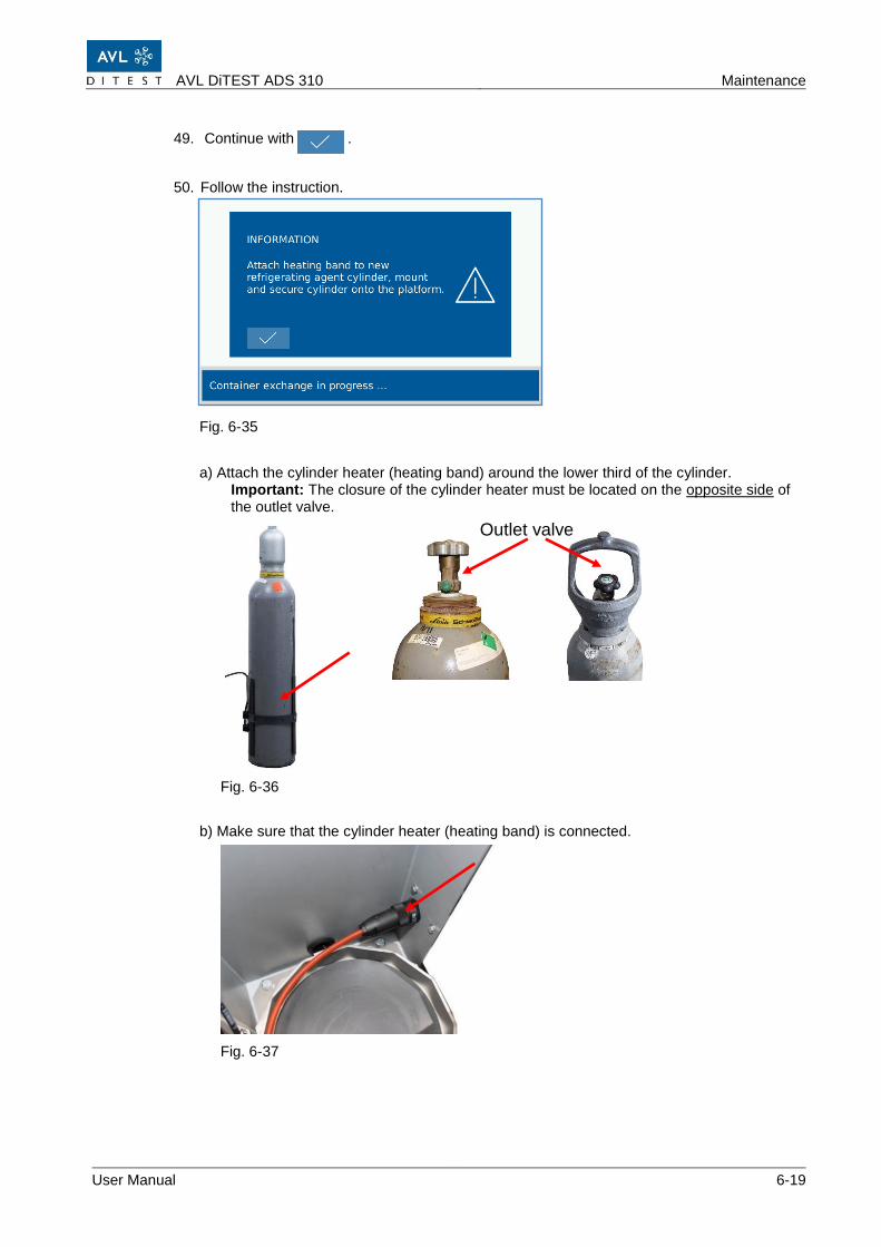
50. Follow the instruction.
Fig. 6-35
a) Attach the cylinder heater (heating band) around the lower third of the cylinder. Important: The closure of the cylinder heater must be located on the opposite side of the outlet valve.
Fig. 6-36
b) Make sure that the cylinder heater (heating band) is connected.
Fig. 6-37
Outlet valve
Maintenance AVL DiTEST ADS 310
6-20 User Manual
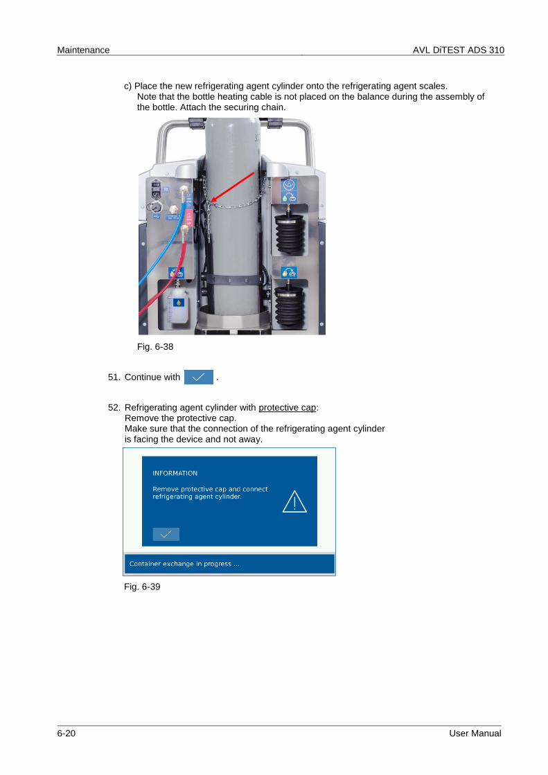
c) Place the new refrigerating agent cylinder onto the refrigerating agent scales. Note that the bottle heating cable is not placed on the balance during the assembly of the bottle. Attach the securing chain.
Fig. 6-38
51. Continue with .
52. Refrigerating agent cylinder with protective cap: Remove the protective cap. Make sure that the connection of the refrigerating agent cylinder is facing the device and not away.
Fig. 6-39
AVL DiTEST ADS 310 Maintenance
User Manual 6-21
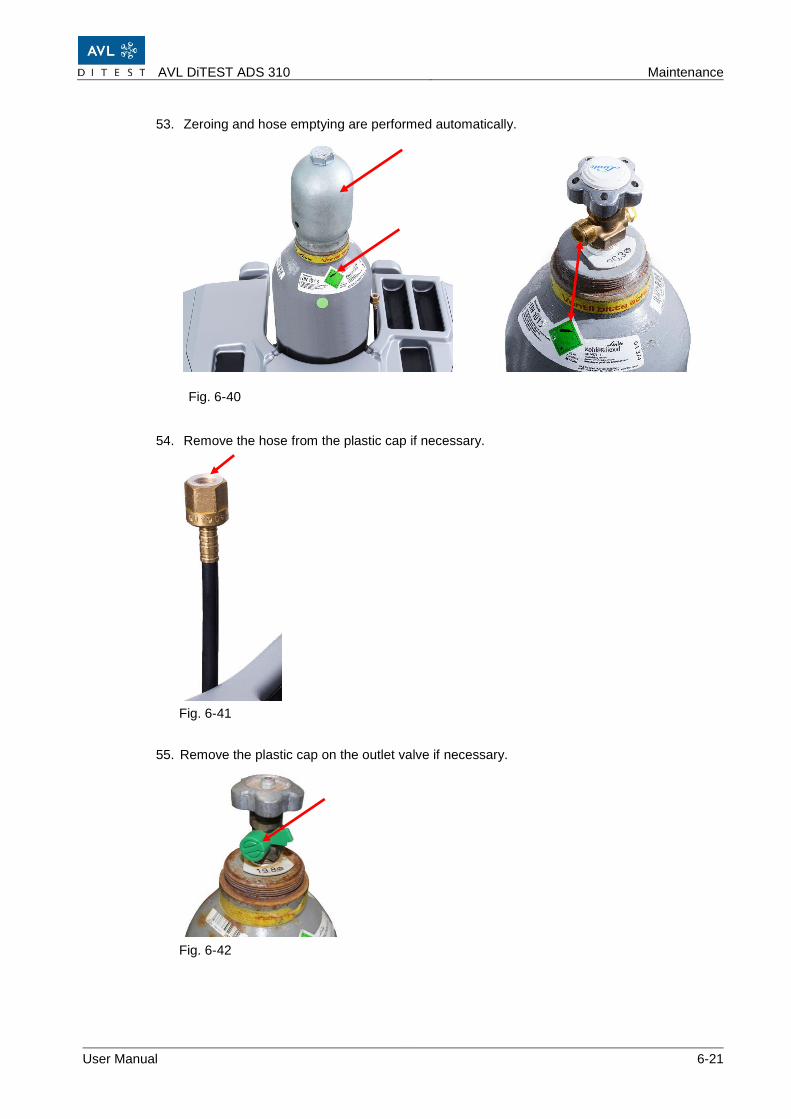
53. Zeroing and hose emptying are performed automatically.
Fig. 6-40
54. Remove the hose from the plastic cap if necessary.
Fig. 6-41
55. Remove the plastic cap on the outlet valve if necessary.
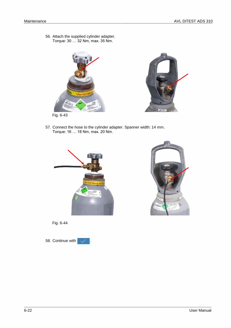
57. Connect the hose to the cylinder adapter. Spanner width: 14 mm. Torque: 16 … 18 Nm, max. 20 Nm.
Fig. 6-44
58. Continue with .
AVL DiTEST ADS 310 Maintenance
User Manual 6-23
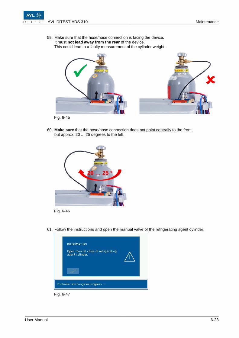
59. Make sure that the hose/hose connection is facing the device. It must not lead away from the rear of the device. This could lead to a faulty measurement of the cylinder weight.
Fig. 6-45
60. Make sure that the hose/hose connection does not point centrally to the front, but approx. 20 ... 25 degrees to the left.
Fig. 6-46
61. Follow the instructions and open the manual valve of the refrigerating agent cylinder.
Fig. 6-47
✓
20 … 25 °
Maintenance AVL DiTEST ADS 310
6-24 User Manual
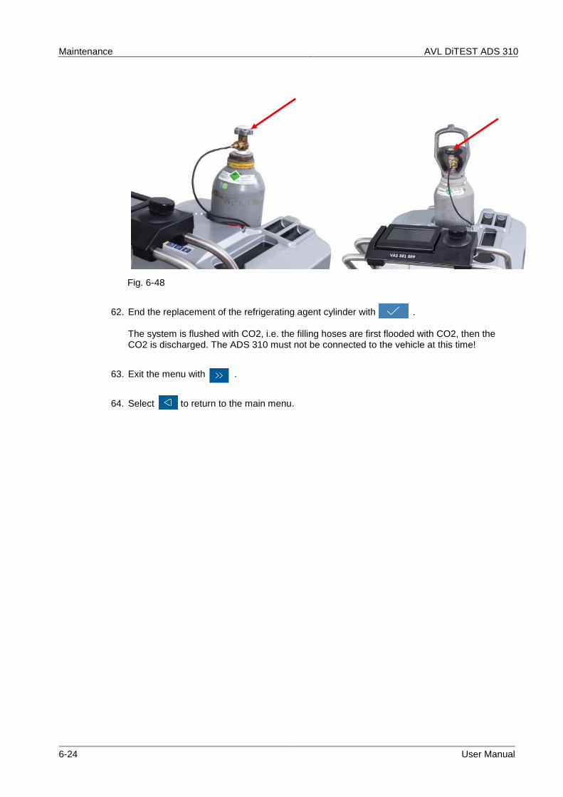
Fig. 6-48
62. End the replacement of the refrigerating agent cylinder with . The system is flushed with CO2, i.e. the filling hoses are first flooded with CO2, then the CO2 is discharged. The ADS 310 must not be connected to the vehicle at this time!
63. Exit the menu with .
64. Select to return to the main menu.
AVL DiTEST ADS 310 Maintenance
User Manual 6-25
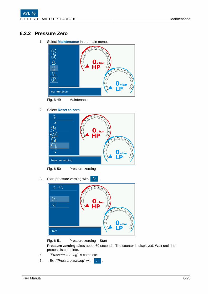
6.3.2 Pressure Zero
1. Select Maintenance in the main menu.
Fig. 6-49 Maintenance
2. Select Reset to zero.
Fig. 6-50 Pressure zeroing
3. Start pressure zeroing with .
Fig. 6-51 Pressure zeroing – Start
Pressure zeroing takes about 60 seconds. The counter is displayed. Wait until the process is complete.
4. "Pressure zeroing" is complete.
5. Exit "Pressure zeroing" with .
Maintenance AVL DiTEST ADS 310
6-26 User Manual
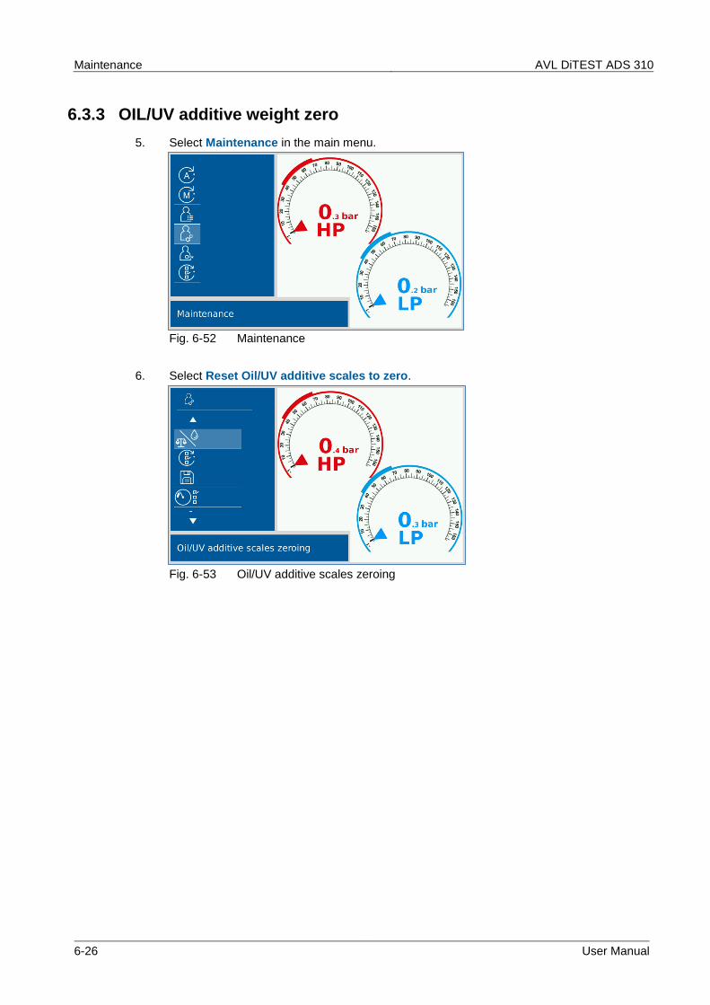
6.3.3 OIL/UV additive weight zero
5. Select Maintenance in the main menu.
Fig. 6-52 Maintenance
6. Select Reset Oil/UV additive scales to zero.
Fig. 6-53 Oil/UV additive scales zeroing
AVL DiTEST ADS 310 Maintenance
User Manual 6-27
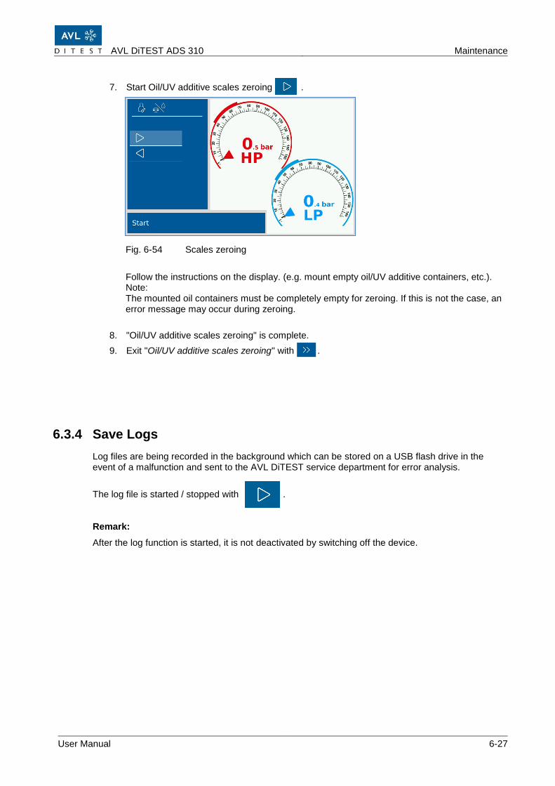
7. Start Oil/UV additive scales zeroing .
Fig. 6-54 Scales zeroing
Follow the instructions on the display. (e.g. mount empty oil/UV additive containers, etc.). Note: The mounted oil containers must be completely empty for zeroing. If this is not the case, an error message may occur during zeroing.
8. "Oil/UV additive scales zeroing" is complete.
9. Exit "Oil/UV additive scales zeroing" with .
6.3.4 Save Logs
Log files are being recorded in the background which can be stored on a USB flash drive in the event of a malfunction and sent to the AVL DiTEST service department for error analysis.
The log file is started / stopped with .
Remark:
After the log function is started, it is not deactivated by switching off the device.
Maintenance AVL DiTEST ADS 310
6-28 User Manual
6.3.5 Change printer paper
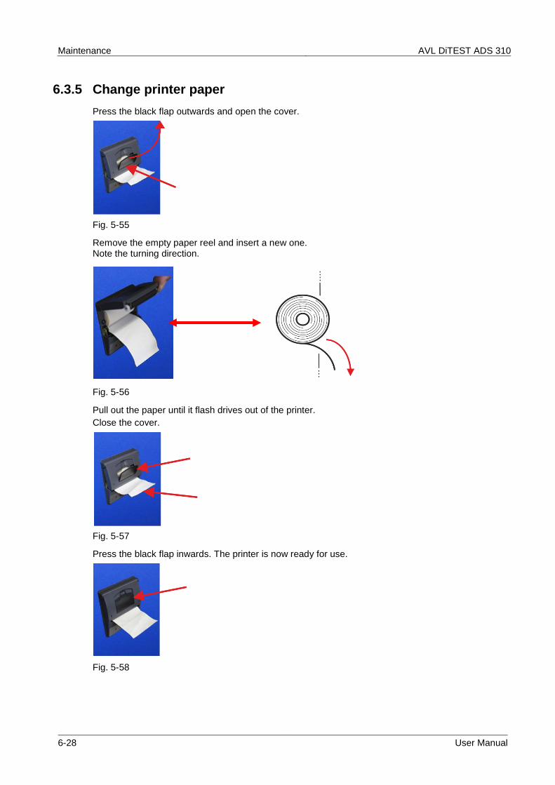
Press the black flap outwards and open the cover.
Fig. 5-55
Remove the empty paper reel and insert a new one. Note the turning direction.
Fig. 5-56
Pull out the paper until it flash drives out of the printer.
Close the cover.
Fig. 5-57
Press the black flap inwards. The printer is now ready for use.
Fig. 5-58
AVL DiTEST ADS 310 Maintenance
User Manual 6-29
6.3.6 Changing the fuses
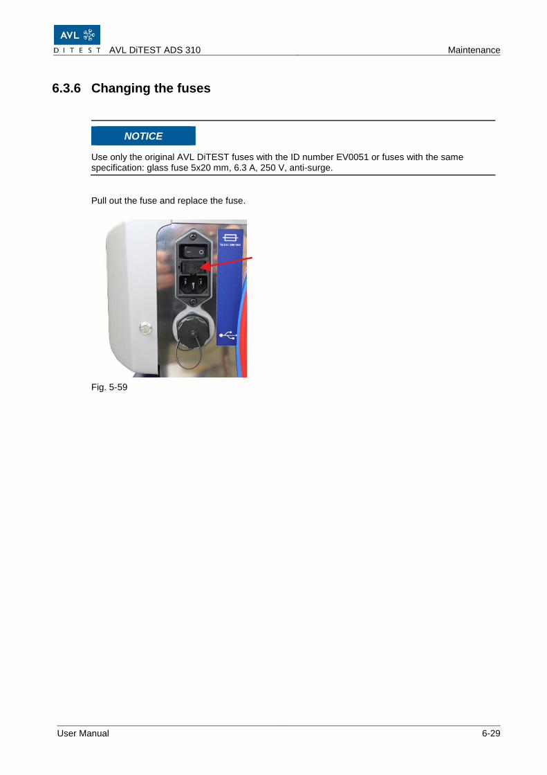
NOTICE
Use only the original AVL DiTEST fuses with the ID number EV0051 or fuses with the same specification: glass fuse 5x20 mm, 6.3 A, 250 V, anti-surge.
Pull out the fuse and replace the fuse.
Fig. 5-59
Maintenance AVL DiTEST ADS 310
6-30 User Manual
6.4 Additional maintenance information
If you experience problems, you can execute various maintenance tasks using the maintenance menu.
Select the desired function.
Follow the instructions on the screen
6.4.1 System information
The menu "System information" shows
▪ the software version
▪ the type of device
▪ the serial number
▪ the hardware version
6.4.2 Operating hours
Shows the total operating hours of the device, the total vacuum pump running time and the number of switching cycles of the individual solenoid valves of the valve block.
AVL DiTEST ADS 310 Maintenance
User Manual 6-31
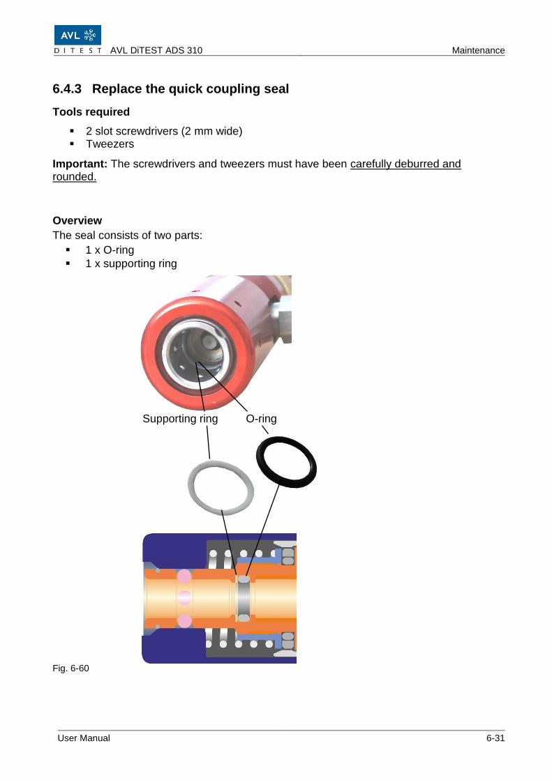
6.4.3 Replace the quick coupling seal
Tools required
▪ 2 slot screwdrivers (2 mm wide) ▪ Tweezers
Important: The screwdrivers and tweezers must have been carefully deburred and rounded.
Overview
The seal consists of two parts:
▪ 1 x O-ring
▪ 1 x supporting ring
Fig. 6-60
Supporting ring O-ring
Maintenance AVL DiTEST ADS 310
6-32 User Manual
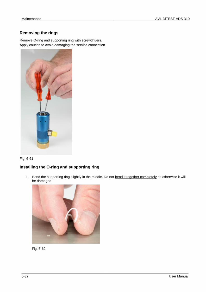
Removing the rings
Remove O-ring and supporting ring with screwdrivers.
Apply caution to avoid damaging the service connection.
Fig. 6-61
Installing the O-ring and supporting ring
1. Bend the supporting ring slightly in the middle. Do not bend it together completely as otherwise it will be damaged.
Fig. 6-62
AVL DiTEST ADS 310 Maintenance
User Manual 6-33
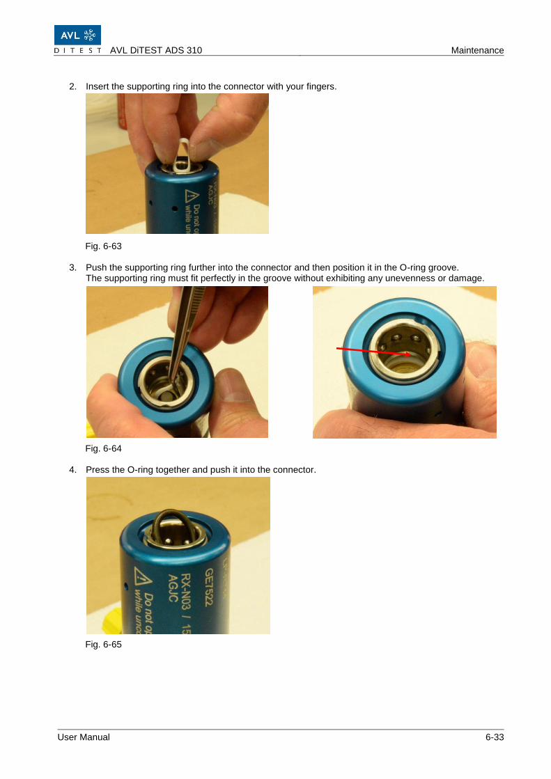
2. Insert the supporting ring into the connector with your fingers.
Fig. 6-63
3. Push the supporting ring further into the connector and then position it in the O-ring groove. The supporting ring must fit perfectly in the groove without exhibiting any unevenness or damage.
Fig. 6-64
4. Press the O-ring together and push it into the connector.
Fig. 6-65
Maintenance AVL DiTEST ADS 310
6-34 User Manual
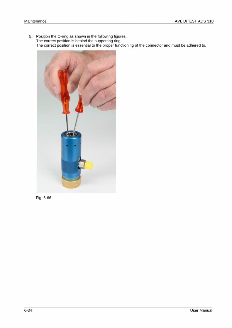
5. Position the O-ring as shown in the following figures. The correct position is behind the supporting ring. The correct position is essential to the proper functioning of the connector and must be adhered to.
Fig. 6-66
AVL DiTEST ADS 310 Maintenance
User Manual 6-35
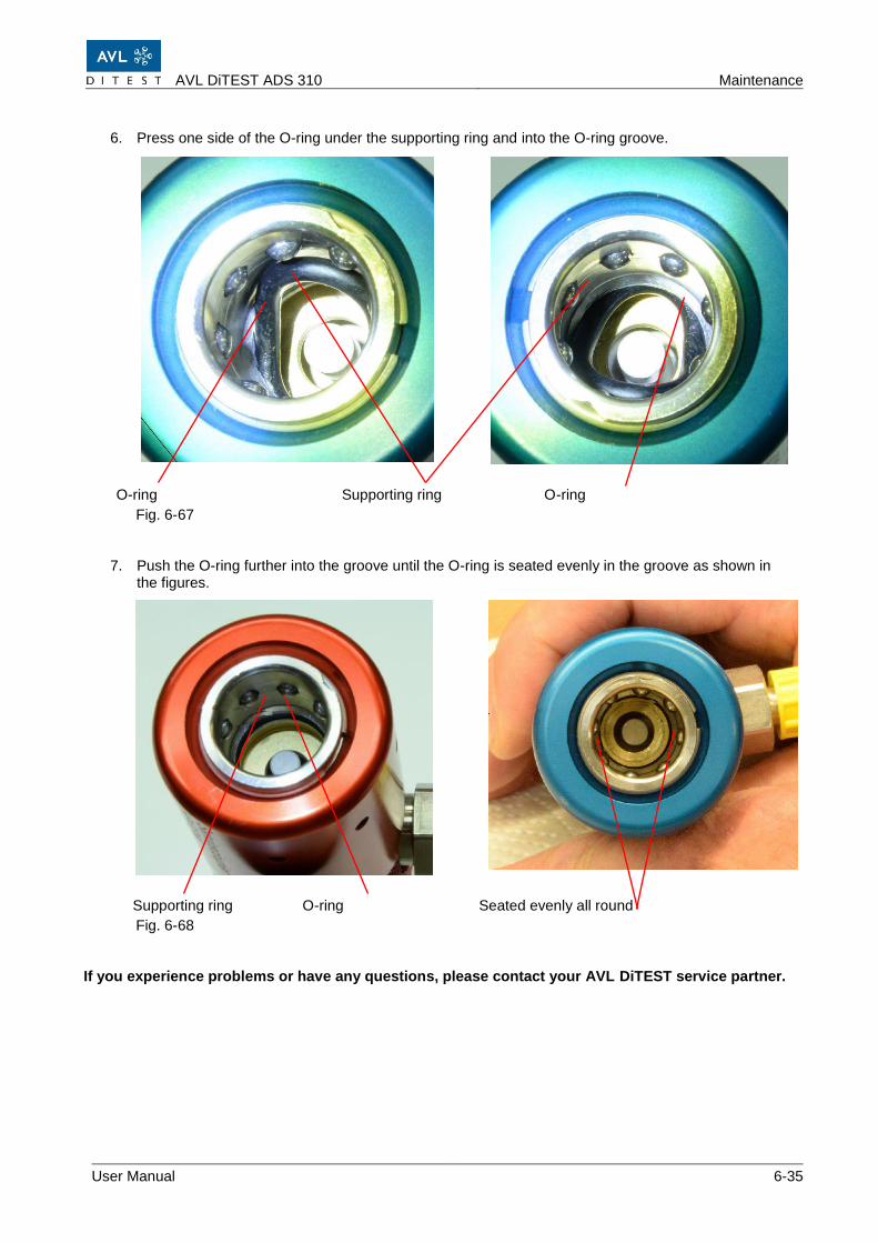
6. Press one side of the O-ring under the supporting ring and into the O-ring groove. O-ring Supporting ring O-ring
Fig. 6-67
7. Push the O-ring further into the groove until the O-ring is seated evenly in the groove as shown in the figures.
Supporting ring O-ring Seated evenly all round
Fig. 6-68 If you experience problems or have any questions, please contact your AVL DiTEST service partner.
Maintenance AVL DiTEST ADS 310
6-36 User Manual
AVL DiTEST ADS 310 Service
User Manual 7-1
7 Service
The operating mode "Service" is password-protected and reserved for the authorized AVL DiTEST service department!
Service AVL DiTEST ADS 310
7-2 User Manual
AVL DiTEST ADS 310 Overview
User Manual 8-1
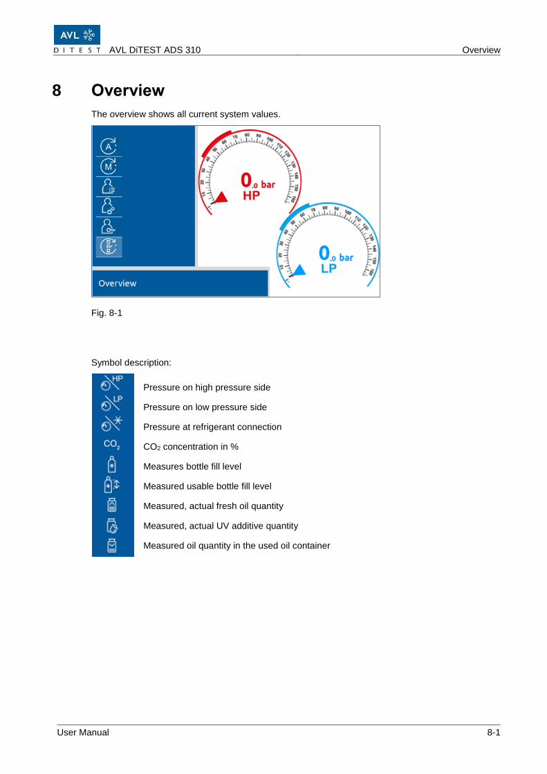
8 Overview
The overview shows all current system values.
Fig. 8-1
Symbol description:
Pressure on high pressure side
Pressure on low pressure side
Pressure at refrigerant connection
CO2 concentration in %
Measures bottle fill level
Measured usable bottle fill level
Measured, actual fresh oil quantity
Measured, actual UV additive quantity
Measured oil quantity in the used oil container
Overview AVL DiTEST ADS 310
8-2 User Manual
AVL DiTEST ADS 310 Shutdown and restart / storage
User Manual 9-1
9 Shutdown and restart / storage
9.1 Shutdown
For the emptying and recycling of refrigerant CO2 (R744), observe the regulations in force in the country of use. If necessary, please contact your service partner.
9.1 Transportation
Information
All applicable safety instructions and accident prevention regulations in the country of use must be observed when transporting this air conditioning service device.
WARNING
Transport only without CO2 bottle, empty or removed bottles, pressure-free ADS 310 and in an upright position!
9.2 Storage
Disconnect the AVL DiTEST ADS 310 from the power supply and place it at a secure location protected from high temperatures, air humidity and any risk of colliding with another object that could damage it. Please also refer to the technical data. The device must also be covered with the enclosed cover. For long storage times, the ext. Remove refrigerant bottle and store separately.
WARNING
Remove CO2 bottle and heating tape when stored above 50 °C!
9.3 Restart
Prior to being taken back into service, the AVL DiTEST ADS 310 must be inspected in accordance with the laws and regulations applicable in the country where it is used.
Shutdown and restart / storage AVL DiTEST ADS 310
9-2 User Manual
9.4 Cleaning
Wipe the ADS 310 with a lint-free cloth. The cloth may be moistened with water or an alkaline detergent. It may be damp but not wet.
CAUION
Before cleaning remove the mains plug! The device must not be pressurized!
Be sure that no liquid is flowing into the housing of the ADS 310!
AVL DiTEST ADS 310 List of possible faults / troubleshooting
User Manual 10-1
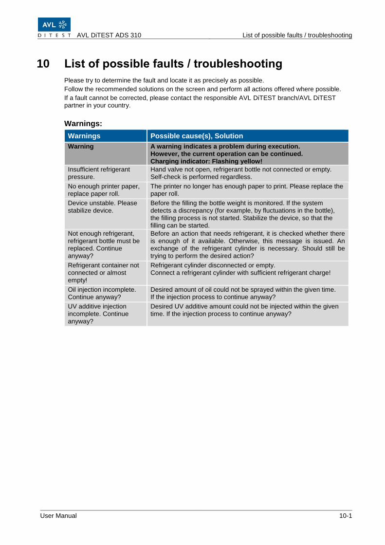
10 List of possible faults / troubleshooting
Please try to determine the fault and locate it as precisely as possible.
Follow the recommended solutions on the screen and perform all actions offered where possible.
If a fault cannot be corrected, please contact the responsible AVL DiTEST branch/AVL DiTEST partner in your country.
Warnings:
Warnings Possible cause(s), Solution
Warning A warning indicates a problem during execution. However, the current operation can be continued. Charging indicator: Flashing yellow!
Insufficient refrigerant pressure.
Hand valve not open, refrigerant bottle not connected or empty. Self-check is performed regardless.
No enough printer paper, replace paper roll.
The printer no longer has enough paper to print. Please replace the paper roll.
Device unstable. Please stabilize device.
Before the filling the bottle weight is monitored. If the system detects a discrepancy (for example, by fluctuations in the bottle), the filling process is not started. Stabilize the device, so that the filling can be started.
Not enough refrigerant, refrigerant bottle must be replaced. Continue anyway?
Before an action that needs refrigerant, it is checked whether there is enough of it available. Otherwise, this message is issued. An exchange of the refrigerant cylinder is necessary. Should still be trying to perform the desired action?
Refrigerant container not connected or almost empty!
Refrigerant cylinder disconnected or empty. Connect a refrigerant cylinder with sufficient refrigerant charge!
Oil injection incomplete. Continue anyway?
Desired amount of oil could not be sprayed within the given time. If the injection process to continue anyway?
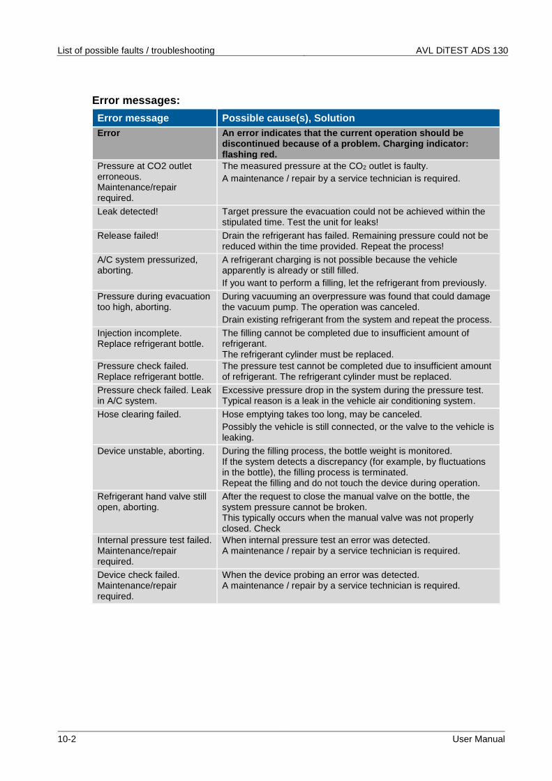
The pressure test cannot be completed due to insufficient amount of refrigerant. The refrigerant cylinder must be replaced.
Pressure check failed. Leak in A/C system.
Excessive pressure drop in the system during the pressure test. Typical reason is a leak in the vehicle air conditioning system.
Hose clearing failed. Hose emptying takes too long, may be canceled.
Possibly the vehicle is still connected, or the valve to the vehicle is leaking.
Device unstable, aborting. During the filling process, the bottle weight is monitored. If the system detects a discrepancy (for example, by fluctuations in the bottle), the filling process is terminated. Repeat the filling and do not touch the device during operation.
Refrigerant hand valve still open, aborting.
After the request to close the manual valve on the bottle, the system pressure cannot be broken. This typically occurs when the manual valve was not properly closed. Check
Internal pressure test failed. Maintenance/repair required.
When internal pressure test an error was detected. A maintenance / repair by a service technician is required.
Device check failed. Maintenance/repair required.
When the device probing an error was detected. A maintenance / repair by a service technician is required.
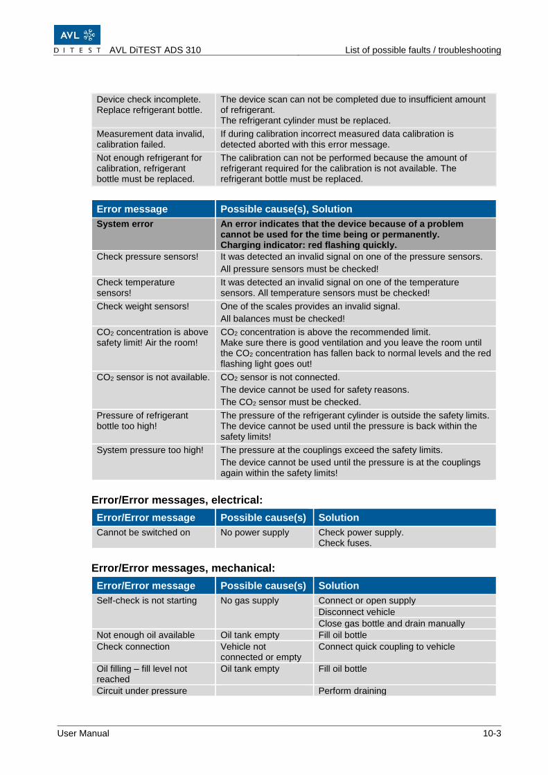
AVL DiTEST ADS 310 List of possible faults / troubleshooting
The device scan can not be completed due to insufficient amount of refrigerant. The refrigerant cylinder must be replaced.
Measurement data invalid, calibration failed.
If during calibration incorrect measured data calibration is detected aborted with this error message.
Not enough refrigerant for calibration, refrigerant bottle must be replaced.
The calibration can not be performed because the amount of refrigerant required for the calibration is not available. The refrigerant bottle must be replaced.
Error message Possible cause(s), Solution
System error An error indicates that the device because of a problem cannot be used for the time being or permanently. Charging indicator: red flashing quickly.
Check pressure sensors! It was detected an invalid signal on one of the pressure sensors.
All pressure sensors must be checked!
Check temperature sensors!
It was detected an invalid signal on one of the temperature sensors. All temperature sensors must be checked!
Check weight sensors! One of the scales provides an invalid signal.
All balances must be checked!
CO2 concentration is above safety limit! Air the room!
CO2 concentration is above the recommended limit. Make sure there is good ventilation and you leave the room until the CO2 concentration has fallen back to normal levels and the red flashing light goes out!
CO2 sensor is not available. CO2 sensor is not connected.
The device cannot be used for safety reasons.
The CO2 sensor must be checked.
Pressure of refrigerant bottle too high!
The pressure of the refrigerant cylinder is outside the safety limits. The device cannot be used until the pressure is back within the safety limits!
System pressure too high! The pressure at the couplings exceed the safety limits.
The device cannot be used until the pressure is at the couplings again within the safety limits!
Error/Error messages, electrical:
Error/Error message Possible cause(s) Solution
Cannot be switched on No power supply Check power supply. Check fuses.
Error/Error messages, mechanical:
Error/Error message Possible cause(s) Solution
Self-check is not starting No gas supply Connect or open supply
Disconnect vehicle
Close gas bottle and drain manually
Not enough oil available Oil tank empty Fill oil bottle
Check connection Vehicle not connected or empty
Connect quick coupling to vehicle
Oil filling – fill level not reached
Oil tank empty Fill oil bottle
Circuit under pressure Perform draining
List of possible faults / troubleshooting AVL DiTEST ADS 130
10-4 User Manual
AVL DiTEST ADS 310 Warranty
User Manual 11-1
11 Warranty
11.1 New Devices
The warranty period for new devices is 12 months.
The agreements made with your supplier apply.
The date on the delivery slip to the end customer applies for handling claims.
The warranty becomes void in the case of:
▪ unscheduled or improper and/or incomplete maintenance
▪ mechanical damage (e.g. if dropped, etc.)
▪ ingress of liquids (e.g. water, oil, acids, etc.)
▪ unauthorized intervention (e.g. repair attempts by unauthorized persons)
▪ incorrect operation (e.g. screen damaged with sharp or pointed objects, cleaning with compressed air)
▪ incorrect storage, maintenance and care (e.g. cleaning the device with solvent-based cleaning agents)
The warranty excludes:
▪ consumables (e.g. paper, filters, oils)
▪ parts subject to natural wear
11.2 Replacement or Loaned Devices
The agreements made with your supplier apply.
The date on the delivery slip to the end customer applies for handling claims.
11.3 Damage Claims
In the event of a damage please contact the AVL DiTEST branch / AVL DiTEST partner in your country.
incl. seal to connect R744 bottle to AVL DiTEST ADS 310
Remark:
It is possible that the supplied bottle adapter does not match with a bottle available in your country. Therefore, a choice of adapters is available as an option. See "Available Accessories".
DN7469
AVL DiTEST ADS 310 documentation DVD
Acceptance report
Shipping Package AVL DiTEST ADS 130
12-2 User Manual
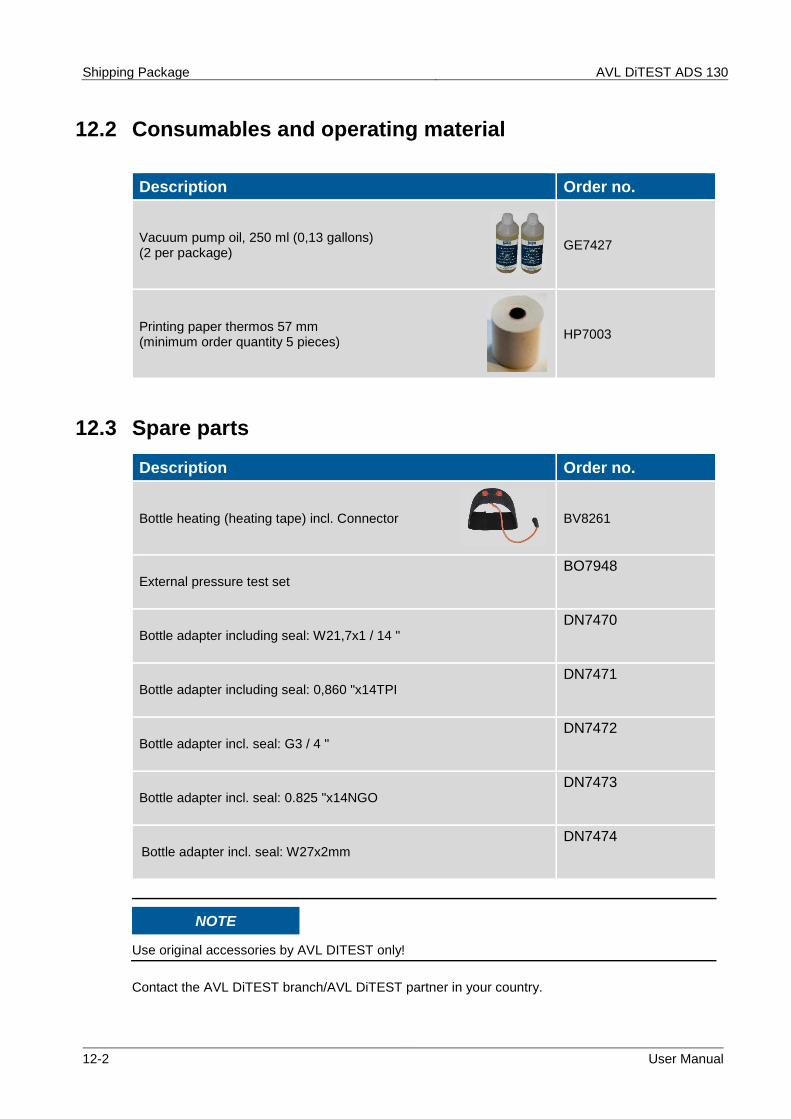
12.2 Consumables and operating material
Description Order no.
Vacuum pump oil, 250 ml (0,13 gallons) (2 per package)
GE7427
Printing paper thermos 57 mm (minimum order quantity 5 pieces)
HP7003
12.3 Spare parts
Description Order no.
Bottle heating (heating tape) incl. Connector
BV8261
External pressure test set
BO7948
Bottle adapter including seal: W21,7x1 / 14 "
DN7470
Bottle adapter including seal: 0,860 "x14TPI
DN7471
Bottle adapter incl. seal: G3 / 4 "
DN7472
Bottle adapter incl. seal: 0.825 "x14NGO
DN7473
Bottle adapter incl. seal: W27x2mm
DN7474
NOTE
Use original accessories by AVL DITEST only!
Contact the AVL DiTEST branch/AVL DiTEST partner in your country.
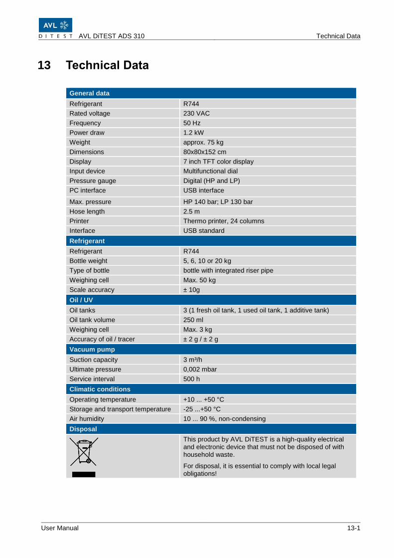
This product by AVL DiTEST is a high-quality electrical and electronic device that must not be disposed of with household waste.
For disposal, it is essential to comply with local legal obligations!
Technical Data AVL DiTEST ADS 130
13-2 User Manual
AVL DiTEST ADS 310 List of Abbreviations
User Manual 14-1
14 List of Abbreviations
Abbreviation Description
ADS AirCondition Diagnostic System
CE Communauté Européenne (European Community)
CO2 Carbon dioxide
EC European Community
HD High pressure
HP High Pressure
IP Internet Protocol
Kfz Motor vehicle
ND Low pressure
HV High Voltage
USB Universal Serial Bus
UV Ultra violet
R744 Workshop name for carbon dioxide CO2
TFT Thin-film transistor display
List of Abbreviations AVL DiTEST ADS 130
14-2 User Manual
AVL DiTEST ADS 310 Index
User Manual 15-1
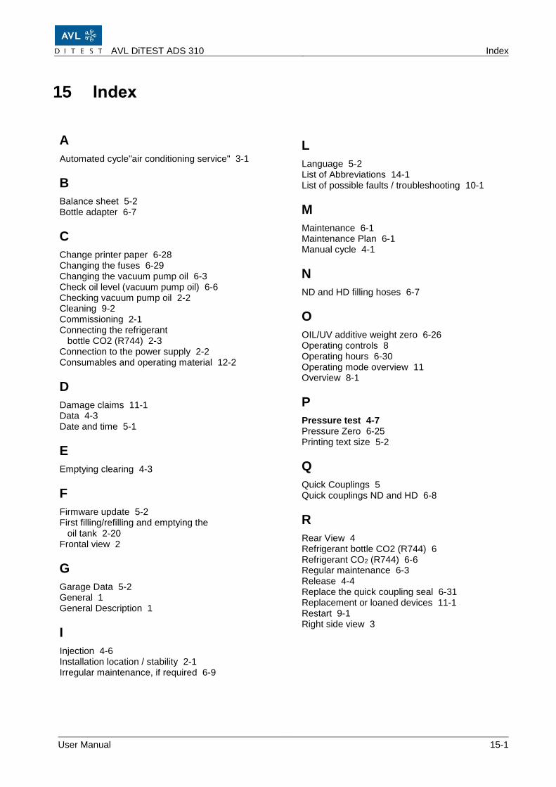
15 Index
A
Automated cycle"air conditioning service" 3-1
B
Balance sheet 5-2 Bottle adapter 6-7
C
Change printer paper 6-28 Changing the fuses 6-29 Changing the vacuum pump oil 6-3 Check oil level (vacuum pump oil) 6-6 Checking vacuum pump oil 2-2 Cleaning 9-2 Commissioning 2-1 Connecting the refrigerant bottle CO2 (R744) 2-3 Connection to the power supply 2-2 Consumables and operating material 12-2
D
Damage claims 11-1 Data 4-3 Date and time 5-1
E
Emptying clearing 4-3
F
Firmware update 5-2 First filling/refilling and emptying the oil tank 2-20 Frontal view 2
Pressure test 4-7 Pressure Zero 6-25 Printing text size 5-2
Q
Quick Couplings 5 Quick couplings ND and HD 6-8
R
Rear View 4 Refrigerant bottle CO2 (R744) 6 Refrigerant CO2 (R744) 6-6 Regular maintenance 6-3 Release 4-4 Replace the quick coupling seal 6-31 Replacement or loaned devices 11-1 Restart 9-1 Right side view 3
Index AVL DiTEST ADS 130
15-2 User Manual
S
SAFETY INSTRUCTIONS III Save Logs 6-27 Service 7-1 Setup 5-1 Shipping Package 12-1 Shutdown 9-1 Shutdown and restart / storage 9-1 Storage 9-1 Switching On 2-21 System Delivery 12-1 System information 6-30
T
Technical Data 13-1 Text and number entry 10 Transportation 9-1
U
Units 5-1 Unpacking 2-1 User interface - operation 9 User prompts 10