46
DOC022.52.80203 2100N 08/2012, Edition 2 User Manual

DOC022.52.80203
2100N08/2012, Edition 2
User Manual


Table of ContentsSpecifications ..................................................................................................................................................................................5
General information .....................................................................................................................................................................6Safety information..............................................................................................................................................................................6Use of hazard information..................................................................................................................................................................6Precautionary labels ..........................................................................................................................................................................6Certification........................................................................................................................................................................................7Product overview...............................................................................................................................................................................7Product components ..........................................................................................................................................................................8
User interface ..................................................................................................................................................................................9
Startup ...............................................................................................................................................................................................10Turn the instrument on.....................................................................................................................................................................10Turn the keypad sound off (optional) ...............................................................................................................................................11
Standard operation ....................................................................................................................................................................11Calibrate the turbidimeter with StablCal® Standards.......................................................................................................................11
Prepare the StablCal standards................................................................................................................................................11Calibration notes.......................................................................................................................................................................11StablCal calibration procedure..................................................................................................................................................12StablCal standards storage......................................................................................................................................................13
Using Gelex secondary standards...................................................................................................................................................13Gelex notes...............................................................................................................................................................................13Measure the Gelex stray light standard....................................................................................................................................14Measure the Gelex secondary turbidity standards...................................................................................................................15Calibration verification..............................................................................................................................................................16Optical system check................................................................................................................................................................16
Prepare a sample cell ......................................................................................................................................................................16Clean the sample cell ...............................................................................................................................................................17Indexing a single sample cell ....................................................................................................................................................18Matching sample cells ..............................................................................................................................................................20Prepare dilution water ...............................................................................................................................................................21
1

Prepare the sample..........................................................................................................................................................................22Prepare a representative sample..............................................................................................................................................22Remove air bubbles from the sample.......................................................................................................................................22
Apply a vacuum.................................................................................................................................................................22Use an ultrasonic bath.......................................................................................................................................................22Apply heat ..........................................................................................................................................................................22
Prevent condensation on a sample cell ....................................................................................................................................23Measure over-range samples...................................................................................................................................................23
Sample dilution..................................................................................................................................................................23Turbidity measurement ....................................................................................................................................................................24
Measurement notes..................................................................................................................................................................24Turbidity measurement procedure............................................................................................................................................25
Measurement techniques.................................................................................................................................................................26Manual or automatic ranging....................................................................................................................................................26Signal averaging on or off .........................................................................................................................................................26Ratio on or off ...........................................................................................................................................................................27Using the air purge system.......................................................................................................................................................27Using a flow cell ........................................................................................................................................................................28
Install a flow cell ................................................................................................................................................................28Clean a flow cell assembly ................................................................................................................................................28Flow cell maintenance.......................................................................................................................................................28Flow cell operation.............................................................................................................................................................28Flow cell storage................................................................................................................................................................29Using a manual flow cell ....................................................................................................................................................29
Use a cell adapter .....................................................................................................................................................................29Install a cell adapter ...........................................................................................................................................................29Remove a cell adapter .......................................................................................................................................................30
Connect to a printer or computer .....................................................................................................................................................30Configure the printer output .............................................................................................................................................................30Configure the RS232 connection.....................................................................................................................................................30Configure a Citizen Model iDP 562RSL II printer .............................................................................................................................30Computer (RS232) commands........................................................................................................................................................31
Table of Contents
2

Advanced operation ..................................................................................................................................................................32Calibrate the turbidimeter with formazin standards..........................................................................................................................32
Prepare formazin standards.....................................................................................................................................................32Calibration notes.......................................................................................................................................................................32Formazin calibration procedure................................................................................................................................................33Making 4000-NTU formazin stock solution...............................................................................................................................35
Calibrate the turbidimeter with user-selected formazin standards...................................................................................................35Prepare formazin standards – user selected............................................................................................................................35Change the calibration points ...................................................................................................................................................35
Maintenance ...................................................................................................................................................................................36Clean the instrument ........................................................................................................................................................................36Change the filter assembly ..............................................................................................................................................................36Clean the filter assembly ..................................................................................................................................................................36Replace the lamp.............................................................................................................................................................................36Replace a fuse.................................................................................................................................................................................38
Troubleshooting ..........................................................................................................................................................................38Error codes .....................................................................................................................................................................................38Diagnostic codes..............................................................................................................................................................................39Delete calibration data.....................................................................................................................................................................39Flashing 9s.......................................................................................................................................................................................40Flashing 0s.......................................................................................................................................................................................40
Replacement parts and accessories ...............................................................................................................................40
Table of Contents
3

Table of Contents
4

SpecificationsSpecifications are subject to change without notice.
Specification Details
Measurement method Nephelometric
Regulatory Meets EPA Method 180.1 ASTM D7315 - Standard Test Method forDetermination of Turbidity Above 1 Turbidity Unit (TU)in Static ModeASTM D6655 - Standard Test Method forDetermination of Turbidity Below 5 NTU in Static Mode
Light source Tungsten filament lamp
Measurement modes NTU, NEPH (Nephelo) and EBC
Range NTU (Ratio on, manual range): 0–0.999, 0–9.99, 0–99.9, 0–4000 NTU (Ratio on, auto range): 0–4000 auto decimalNTU (Ratio off): 0–40.0 Nephelo (Ratio on, manual range): 0–9.99, 0–99.9, 0–26,800 Nephelo (Ratio on, auto range): 0–26,800 autodecimalNephelo (Ratio off): 0–268 EBC (Ratio on, manual range): 0–0.999, 0–9.99, 0–99.9, 0–980 EBC (Ratio on, auto range): 0–980 auto decimalEBC (Ratio off): 0–9.8
Accuracy1, 2 Ratio on: ±2% of reading plus 0.01 NTU from 0–1000 NTU, ±5% of reading from 1000–4000 NTUbased on formazin primary standardRatio off: ±2% of reading plus 0.01 NTU from 0–40 NTU (under reference conditions3)
Resolution Turbidity: 0.001 NTU/EBC, Nephelo (on lowest range)
Specification Details
Repeatability ±1% of reading or 0.01 NTU, whichever is greater(under reference conditions)
Response time Signal averaging off: 6.8 secondsSignal averaging on: 14 seconds (when10 measurements are used to calculate the average)
Stabilization time Ratio on: 30 minutes after start-upRatio off: 60 minutes after start-up
Reading modes Manual or auto range, signal averaging on or off, Ratioon or off
Power requirement 115–230 VAC, 50/60 Hz (automatic power selection)28 W maximum
Pollutiondegree/installationcategory
2; II
Protection Class 1
Operating conditions Temperature: 0 to 40 °C (32 to 104 °F)Relative humidity: 0–90% at 25 °C, 0–75% at 40 °C,noncondensingAltitude: 2000 m (6560 ft) maximumIndoor use only
Storage conditions –40 to 60 °C (–40 to 140 °F), instrument only
Interface RS232C serial interface by way of DB9 subminiatureD-shell connector for data output to computer orprinter, and data input (command). No handshaking.
Air purge Dry nitrogen or instrument grade air (ANSI MC 11.1,1975)0.1 scfm at 69 kPa (10 psig); 138 kPa (20 psig)maximumHose barb connection for 1/8-inch tubing
English 5

Specification Details
Sample cells Round cells 95 x 25 mm (3.74 x 1 in.) borosilicateglass with rubber-lined screw capsNote: Smaller sample cells (less than 25 mm) can be usedwhen a cell adapter is used.
Sample requirements 25 mm sample cell: 20 mL minimum0 to 95 °C (32 to 203 °F)Note: Refer to Use a cell adapter on page 29 for the minimumsample size when not using a 25 mm sample cell.
Enclosure High-impact polycarbonate plastic
Dimensions 30.5 x 40 x 15.6 cm (12.0 x 15.7 x 6.1 in.)
Weight 3.4 kg (7.5 lb)
Certification CE, cETLus
1 Turbidity specifications identified using USEPA filter assembly, recentlyprepared formazin standard and matched 1-inch sample cells.
2 Intermittent electromagnetic radiation of 3 volts/meter or greater may causeslight accuracy shifts.
3 Reference conditions: 0–40 °C, 0–90% RH noncondensing at 25 °C,115/230 VAC, 50/60 Hz
General informationIn no event will the manufacturer be liable for direct, indirect, special,incidental or consequential damages resulting from any defect oromission in this manual. The manufacturer reserves the right to makechanges in this manual and the products it describes at any time, withoutnotice or obligation. Revised editions are found on the manufacturer’swebsite.
Safety informationN O T I C E
The manufacturer is not responsible for any damages due to misapplication ormisuse of this product including, without limitation, direct, incidental andconsequential damages, and disclaims such damages to the full extent permittedunder applicable law. The user is solely responsible to identify critical applicationrisks and install appropriate mechanisms to protect processes during a possibleequipment malfunction.
Please read this entire manual before unpacking, setting up or operatingthis equipment. Pay attention to all danger and caution statements.Failure to do so could result in serious injury to the operator or damageto the equipment.Make sure that the protection provided by this equipment is not impaired.Do not use or install this equipment in any manner other than thatspecified in this manual.
Use of hazard information
D A N G E R Indicates a potentially or imminently hazardous situation which, if not avoided, willresult in death or serious injury.
W A R N I N G Indicates a potentially or imminently hazardous situation which, if not avoided,could result in death or serious injury.
C A U T I O N Indicates a potentially hazardous situation that may result in minor or moderateinjury.
N O T I C E Indicates a situation which, if not avoided, may cause damage to the instrument.Information that requires special emphasis.
Precautionary labelsRead all labels and tags attached to the instrument. Personal injury ordamage to the instrument could occur if not observed. A symbol, if noted
6 English
on the instrument, will be included with a danger or caution statement inthe manual.
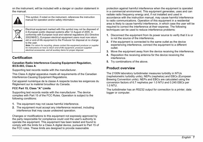
This symbol, if noted on the instrument, references the instructionmanual for operation and/or safety information.
Electrical equipment marked with this symbol may not be disposed ofin European public disposal systems after 12 August of 2005. Inconformity with European local and national regulations (EU Directive2002/96/EC), European electrical equipment users must now returnold or end-of-life equipment to the Producer for disposal at no chargeto the user.Note: For return for recycling, please contact the equipment producer or supplierfor instructions on how to return end-of-life equipment, producer-suppliedelectrical accessories, and all auxiliary items for proper disposal.
CertificationCanadian Radio Interference-Causing Equipment Regulation,IECS-003, Class A:Supporting test records reside with the manufacturer.This Class A digital apparatus meets all requirements of the CanadianInterference-Causing Equipment Regulations.Cet appareil numèrique de la classe A respecte toutes les exigences duRëglement sur le matériel brouilleur du Canada.FCC Part 15, Class "A" LimitsSupporting test records reside with the manufacturer. The devicecomplies with Part 15 of the FCC Rules. Operation is subject to thefollowing conditions:
1. The equipment may not cause harmful interference.2. The equipment must accept any interference received, including
interference that may cause undesired operation.
Changes or modifications to this equipment not expressly approved bythe party responsible for compliance could void the user's authority tooperate the equipment. This equipment has been tested and found tocomply with the limits for a Class A digital device, pursuant to Part 15 ofthe FCC rules. These limits are designed to provide reasonable
protection against harmful interference when the equipment is operatedin a commercial environment. This equipment generates, uses and canradiate radio frequency energy and, if not installed and used inaccordance with the instruction manual, may cause harmful interferenceto radio communications. Operation of this equipment in a residentialarea is likely to cause harmful interference, in which case the user will berequired to correct the interference at their expense. The followingtechniques can be used to reduce interference problems:
1. Disconnect the equipment from its power source to verify that it is oris not the source of the interference.
2. If the equipment is connected to the same outlet as the deviceexperiencing interference, connect the equipment to a differentoutlet.
3. Move the equipment away from the device receiving the interference.4. Reposition the receiving antenna for the device receiving the
interference.5. Try combinations of the above.
Product overviewThe 2100N laboratory turbidimeter measures turbidity in NTUs(nephelometric turbidity units), NEPs (nephelos) and EBCs (EuropeanBrewing Convention units). NEPs and EBCs are calculated using theconversion factors of 6.7 nephelos per 1.0 NTU and 0.245 EBCs per1.0 NTU.The turbidimeter has an RS232 output for connection to a printer, datalogger or computer.
English 7

Figure 1 Front overview
1 Keypad 4 Cover for the sample cellcompartment
2 Sample cell holder 5 Five-digit LED display
3 Light shield
Figure 2 Back overview
1 Power cord connector 4 DB9 connector for RS232 cable
2 Fuse holder 5 Air purge fitting
3 Power switch 6 Lamp access cover
Product componentsRefer to Figure 3 to make sure that all components have been received.If any of these items are missing or damaged, contact the manufactureror a sales representative immediately.
Figure 3 Instrument components
1 2100N turbidimeter 6 StablCal® Calibration kit
2 USEPA filter assembly 7 Gelex® secondary turbiditystandardization kit1
3 Oiling cloth 8 Dust cover
4 Six 1" sample cells (30 mL) withcaps
9 Power cord
5 Silicone oil
1 Supplied with 4700000 only.
8 English
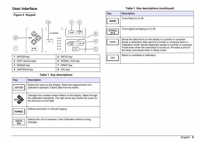
User interfaceFigure 4 Keypad
1 ENTER key 5 RATIO key
2 EDIT (arrow) keys 6 SIGNAL AVG key
3 RANGE key 7 PRINT key
4 UNITS/Exit key 8 CAL key
Table 1 Key descriptions
Key Description
Enters the value on the display. Starts the measurement of acalibration standard. Clears data from the buffer.
Changes the numbers and/or letters on the display. Steps throughthe calibration standards. The right arrow key moves the cursor tothe previous or next digit.
Selects automatic or manual ranging.
Selects the unit of measure. Exits Calibration without savingchanges.
Table 1 Key descriptions (continued)
Key Description
Turns Ratio on or off.
Turns signal averaging on or off.
Sends the data that is on the display to a printer or computer.Sends a calibration data report to a printer or computer when inCalibration mode. Sends diagnostic results to a printer or computerif held down when the instrument is turned on. Provides a print ofthe setup commands when in Setup mode.
Starts or completes a calibration.
English 9

Figure 5 Indicator lights
1 NEPH light 6 Auto Range light
2 EBC light 7 CAL? light
3 NTU light 8 RATIO light
4 Lamp light 9 SIGNAL AVG light
5 Manual Range light 10 S0–S4 lights
Table 2 Light descriptions
Light Description
NEPH Illuminated when the instrument is set for NEPH (nephelo) unit ofmeasure.
EBC Illuminated when the instrument is set for EBC unit of measure.
NTU Illuminated when the instrument is set for NTU unit of measure.
Table 2 Light descriptions (continued)
Light Description
Illuminated when the instrument light source is on.Flashes when there is not sufficient light for measurement.
ManualRange
Illuminated when the instrument is in manual ranging mode.
AutoRange
Illuminated when the instrument is in auto ranging mode.
CAL? Turns on during a calibration if the calibration data is not within theacceptable range.Flashes when the instrument should be calibrated.Note: The CAL? light applies when the USEPA filter and a 25-mm sample cell areused. Ignore the CAL? light if illuminated during calibration when a different filteror a smaller sample cell is used. Push UNITS/Exit to start measurements.
RATIO Illuminated when Ratio is on.
SIGNALAVG
Illuminated when signal averaging is on.
S0–S4 Show the current calibration point standard that is in use duringcalibration.
Startup
Turn the instrument on
1. Put the instrument on a stable, level surface that is free of vibration.Do not put in direct sunlight.
2. Make sure that there is air circulation around the instrument. Keepthe back and area below the instrument free of material that coulddecrease air flow through the vents.
3. Connect the power cord to the power plug on the back of theinstrument.
4. Connect the power cord to a power socket with ground contact.
10 English
5. Push the power switch on the back of the instrument to turn theinstrument on.
Turn the keypad sound off (optional)By default, the instrument makes an audible sound when a key ispushed. To turn the keypad sound off:
1. Push and hold down the right arrow key for 3 seconds.2. Use the arrow keys to select 00.3. Push ENTER.4. Use the arrow keys to select the sound option:
Option Description
bP on An audible sound is made when a key is pushed.
bP oF No sound is made when a key is pushed.
5. Push ENTER.
Standard operation
Calibrate the turbidimeter with StablCal® StandardsCalibrate the turbidimeter before it is used for the first time using theStablCal® sealed vial standards provided. As an alternative, calibrationcan be done with recently prepared formazin standards. Refer to Calibrate the turbidimeter with formazin standards on page 32.Calibrate the turbidimeter at least every 3 months or as specified by theregulating authority when data is used for USEPA reporting.The instrument is ready for calibration 60 minutes after start-up. Keepthe instrument on 24 hours a day if the instrument is used regularly.Note: Unknown results may occur if standards other than the recommendedcalibration points are used. The recommended calibration points (< 0.1, 20, 200,1000 and 4000 NTU) provide the best calibration accuracy. Use of standards otherthan StablCal, or user-prepared formazin, may result in less accurate calibrations.The manufacturer cannot guarantee the performance of the instrument if calibratedwith co-polymer styrenedivinylbenzene beads or other suspensions.
Prepare the StablCal standardsWhen received and at intervals:
1. Clean the exterior surface of the StablCal vials with laboratory glasscleaning detergent.
2. Rinse the vials with distilled or deionized water.3. Dry the vials with a lint-free cloth.
Note: Never shake or invert the < 0.1 NTU standard. If the standard has beenmixed or shaken, do not move the vial for 15 minutes or more before using.Note: Do not remove the caps from the sealed vials.
Make sure that the StablCal standards are at ambient instrumenttemperature before use (and no greater than 40 °C (104 °F)).Mix the standards before use:
1. Open the case lid. Remove the < 0.1 NTU standard from the plasticcase.
2. Leave the other standards in the case. Close the case lid.3. Shake the case vigorously for at least 10 seconds.4. Let the standards stand with no movement for 3–5 minutes before
use.
Calibration notes
• Make sure that the instrument is in the same ambient conditions aswhere it is used.
• Make sure that the standards are at the same ambient temperature asthe instrument before use.
• Use only the provided silicone oil. This silicone oil has the samerefractive index as the vial glass and masks minor glass differencesand scratches.
• Store the oiling cloth in a plastic storage bag to keep the cloth clean.• If power is lost during calibration, the new calibration data is lost and
the last calibration data is used. To exit a calibration and not save thenew values, push UNITS/Exit.
• In Calibration mode, automatic range and signal averaging on areselected. When calibration is completed, all operational modes goback to the last settings.
English 11

• All nephelometric (turbidity units of measure) calibrations are done atthe same time.
• Ratio-on and Ratio-off calibration data is measured and recorded atthe same time.
• Clean the USEPA filter assembly before doing a primary calibration,or at least every 3 months (which is the USEPA-recommendedprimary calibration interval).
StablCal calibration procedure
1. Remove the filterassembly. Refer to Change the filterassembly on page 36.
2. Clean the lens of theUSEPA filter assembly.Refer to Clean the filterassembly on page 36.
3. Hold the tab of theUSEPA filter assemblyso that the arrows pointtoward the front of theinstrument. Push thefilter assembly fully inthe housing.
4. Push CAL.The S0 light turns on.The NTU value of thedilution water used inthe last calibration isshown on the display.
5. Get the < 0.1 NTUvial. Clean the vial witha soft, lint-free cloth toremove water spots andfingerprints. Do notinvert the vial.
6. Apply a small beadof silicone oil from thetop to the bottom of thevial.
12 English

7. Use the oiling clothto apply the oil equallyto the surface of thevial. Remove theexcess oil. Make surethat the vial is almostdry.
8. Put the vial in thesample cell holder withthe triangle on the vialaligned with thereference mark on thesample cell holder.Close the cover.
9. Push ENTER.The instrument displaycounts down, thenmeasures the standard.The next expectedstandard (e.g., 20.00) isshown. The S1 lightturns on.
10. Remove the vialfrom the sample cellholder.
11. Do steps 5–10 forthe other StablCal vials(from lowest to highestNTU standard).The S0 light turns onafter the last vial ismeasured.
12. Push CAL.The instrument savesthe new calibration dataand goes back toMeasurement mode.
StablCal standards storage
• Do not move a StablCal standard to a different container for storage.Keep StablCal standards in the plastic case provided with the coverclosed.
• Store at 5 to 25 °C (41 to 77 °F).• For long-term storage (more than one month between use), keep at
5 °C (41 °F).
Using Gelex secondary standardsThe Gelex secondary standards are used when a calibration check or anoptical system check is done. Refer to Calibration verificationon page 16 and Optical system check on page 16.
Gelex notes
• Measure the Gelex secondary standards on the instrument on whichthey will be used. The measured values can only be used for one
instrument due to small differences in glass and instrument opticalsystems.
• Do not keep a Gelex vial in the instrument for more time than isnecessary to complete measurement. The heat from the lamp canchange the turbidity value of a Gelex vial.
• Keep the Gelex standards at room temperature. Do not let Gelexstandards freeze or become warmer than 50 °C (122 °F). Hightemperatures may cause Gelex suspensions to divide.
• Make sure that the Gelex standards are at ambient instrumenttemperature before measurement.
English 13

Measure the Gelex stray light standardMeasure the Gelex stray light standard when the instrument is first received. Record the value on the Gelex vial with a permanent marker one time.
1. Clean the stray lightstandard with a soft,lint-free cloth to removewater spots andfingerprints.
2. Apply a small beadof silicone oil from thetop to the bottom of thevial.
3. Use the oiling clothto apply the oil equallyto the surface of thevial. Remove theexcess oil. Make surethat the vial is almostdry.
4. Push RANGE toselect automaticranging.The Auto Range lightturns on.
5. Push SIGNAL AVGto turn signal averagingoff.The SIGNAL AVG lightturns off.
6. Push UNITS/Exit toselect the NTUmeasurement mode.The NTU light turns on.
7. Push RATIO to turnRatio mode on.
8. Put the stray lightstandard in the samplecell holder with thetriangle on the vialaligned with thereference mark on thesample cell holder.Close the cover.
9. Read the valuewhen stable. Removethe vial from theinstrument.
10. Record the valueon the white diamondspace on the vial usinga permanent marker.
14 English

Measure the Gelex secondary turbidity standardsMeasure the Gelex secondary turbidity standards each time the instrument is calibrated and record the new values on the Gelex vials with a watersoluble marker.
1. Clean the Gelexvials with a soft, lint-freecloth to remove waterspots and fingerprints.
2. Apply a small beadof silicone oil from thetop to the bottom of thevial.
3. Use the oiling clothto apply the oil equallyto the surface of thevial. Remove theexcess oil. Make surethat the vial is almostdry.
4. Push RANGE toselect automaticranging.The Auto Range lightturns on.
5. Push SIGNAL AVGto turn signal averagingoff.The SIGNAL AVG lightturns off.
6. Push UNITS/Exit toselect the NTUmeasurement mode.The NTU light turns on.
English 15

7. Push RATIO toselect Ratio on or off.Ratio must be on forGelex standardsgreater than 40 NTU.For the 0–2 and 0–20 NTU Gelexstandards, select theRatio function that theinstrument will operatein.
8. Put the 0–2 NTUGelex vial in the samplecell holder with thetriangle on the vialaligned with thereference mark on thesample cell holder.Close the cover.
9. Read the valuewhen stable. Removethe vial from theinstrument.
10. Record the valueon the white diamondspace on the vial usinga water soluble marker.Record on the vial ifRatio was on or offwhen the vial wasmeasured.
11. Do steps 7–10 forthe other Gelex vials(but not the stray lightstandard). Measurefrom lowest to highestNTU.
Calibration verificationAt intervals, measure the Gelex secondary turbidity standard that isclosest in value to the turbidity range to be measured. Do the steps in Measure the Gelex secondary turbidity standards on page 15, but do notchange the value that is recorded on the vial.Turn Ratio on if the Gelex vial is greater than 40 NTU. Select the Ratiosetting recorded on the Gelex vial for vials less than 40 NTU.If the measured value is within ±5% of the value recorded on the Gelexvial, calibration is verified. If not, calibrate the instrument.Note: The StablCal® primary turbidity standards can also be used to do acalibration check. Prepare the StablCal vials before use. Refer to Prepare theStablCal standards on page 11. Do not use the < 0.1 NTU StablCal vial as it doesnot have an accurately identified NTU value. The instrument is calibrated if themeasured value is within ±5% of the StablCal value.
Optical system checkAt intervals, measure the Gelex stray light standard to inspect theintegrity of the optical system. Do the steps in Measure the Gelex straylight standard on page 14, but do not change the value that is recordedon the vial.If the value measured is similar to the value recorded on the Gelex straylight standard (within ±0.02 NTU), the instrument works correctly. If not,contact Customer Service.
Prepare a sample cellUse a clean sample cell(s) for sample measurement.Note: As an alternative, a flow cell can be used for sample measurement. Refer to Using a flow cell on page 28.
16 English
Clean the sample cell
C A U T I O N
Chemical exposure hazard. Obey laboratory safety procedures andwear all of the personal protective equipment appropriate to thechemicals that are handled. Refer to the current material safety datasheets (MSDS) for safety protocols.
N O T I C E Do not air dry the sample cells. Always store the sample cells with caps on toprevent the cells from drying. For storage, fill the sample cell with distilled ordemineralized water.
1. Clean the internal and external surfaces of the sample cell and capwith a laboratory glass cleaning detergent.
2. Fully rinse the sample cell many times with distilled or deionizedwater.
3. Clean the internal and external surfaces of the sample cell and capwith 1:1 hydrochloric acid.
4. Fully rinse the sample cell many times with distilled or deionizedwater.Note: If the sample cell will be used to measure low range turbidity samples ordilution water, rinse with dilution water (not distilled or deionized water). Referto Prepare dilution water on page 21.
5. Dry the external surface of the sample cell with a soft, lint-free cloth.6. Fill the sample cell with distilled or deionized water.
Note: If the sample cell will be used to measure low range turbidity samples ordilution water, fill the sample cell with dilution water (not distilled or deionizedwater).
7. Immediately put the cap on the sample cell.Note: Hold the sample cell by the top only to minimize dirt and fingerprints.
English 17

Indexing a single sample cellWhen measuring very low turbidity samples, use a single indexed sample cell or a flow cell for all measurements to get precise and repeatablemeasurements. As an alternative, optically matched sample cells can be used. Refer to Matching sample cells on page 20. Matched sample cells donot provide as good of accuracy and precision as a single indexed sample cell that is used for every measurement or a flow cell.
1. Rinse a clean,empty sample cell twotimes with dilution waterand drain to waste. Fillthe sample cell to theline (about 30 mL) withdilution water andimmediately put the capon the sample cell.Refer to Preparedilution wateron page 21.Let the sample cell sitfor at least five minutesto degas.
2. Clean the samplecell with a soft, lint-freecloth to remove waterspots and fingerprints.
3. Apply a small beadof silicone oil from thetop to the bottom of thesample cell.
4. Use the oiling clothprovided to apply the oilequally to the surface ofthe sample cell.Remove the excess oil.Make sure that thesample cell is almostdry.
5. Put the sample cellin the sample cellholder. Close the cover.Record the value whenstable.
6. Remove the samplecell, turn it about 1/8 of aturn and put it in thesample cell holderagain. Close the cover.Record the value whenstable.
18 English

7. Repeat step 6 untilthe lowest value isshown on the display.
8. Put an orientationmark on the markingband near the top of thesample cell where thelowest value is shown.
English 19
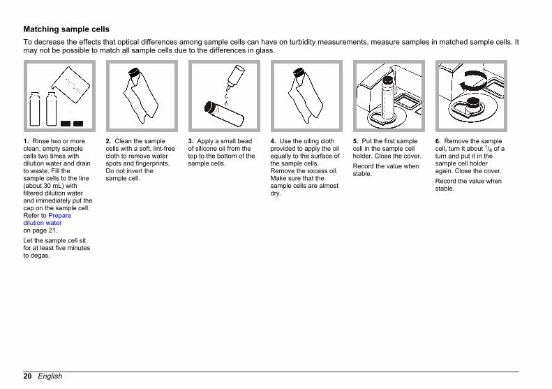
Matching sample cellsTo decrease the effects that optical differences among sample cells can have on turbidity measurements, measure samples in matched sample cells. Itmay not be possible to match all sample cells due to the differences in glass.
1. Rinse two or moreclean, empty samplecells two times withdilution water and drainto waste. Fill thesample cells to the line(about 30 mL) withfiltered dilution waterand immediately put thecap on the sample cell.Refer to Preparedilution wateron page 21.Let the sample cell sitfor at least five minutesto degas.
2. Clean the samplecells with a soft, lint-freecloth to remove waterspots and fingerprints.Do not invert thesample cell.
3. Apply a small beadof silicone oil from thetop to the bottom of thesample cells.
4. Use the oiling clothprovided to apply the oilequally to the surface ofthe sample cells.Remove the excess oil.Make sure that thesample cells are almostdry.
5. Put the first samplecell in the sample cellholder. Close the cover.Record the value whenstable.
6. Remove the samplecell, turn it about 1/8 of aturn and put it in thesample cell holderagain. Close the cover.Record the value whenstable.
20 English

7. Repeat step 6 untilthe lowest value isshown on the display.
8. Record the value.Put an orientation markon the marking bandnear the top of thesample cell.
9. Put the secondsample cell in thesample cell holder.Close the cover.Record the value whenstable.
10. Remove thesample cell, turn itabout 1/8 of a turn andput it in the sample cellholder again. Close thecover.Record the value whenstable.
11. Repeat step10 until the valuematches the firstsample cell value within±0.005 NTU.
12. Put an orientationmark on the markingband near the top of thesample cell where thelowest value is shown.
13. Do steps 9–12 again as necessaryto match the othersample cells preparedin steps 1–4.
Prepare dilution waterDilution water is used when indexing a sample cell or matching samplecells and to prepare formazin standards.
1. Collect at least 1000 mL of high-quality, low-turbidity water (i.e.,distilled, demineralized or deionized water or filtered tap water).
2. Measure the turbidity of the water using the turbidimeter. Refer to Turbidity measurement on page 24.
3. If the turbidity of the water is greater than 0.5 NTU, filter the waterusing the sample filtration and degassing kit. Refer to the userinstructions provided with the sample filtration and degassing kit.
English 21

Prepare the sampleProper sampling techniques are important to get accuratemeasurements.
Prepare a representative sampleA representative sample accurately reflects the true condition ofthe water source from which the sample was taken.To prepare a representative sample:
• Gently but fully mix every sample before collecting aliquots (sampleportions). Mix by gentle inversion only. Do not shake.
• When collecting a sample from a water tap in a distribution system ortreatment plant, turn the water on for at least five minutes, then collectthe sample.
• When collecting a sample from a body of water (e.g., a stream orstorage tank), collect at least one liter (1 quart) and fully mix beforetaking an aliquot for measurement. If the quality of the sample sourceis not constant, collect samples at many locations at different depthsas necessary. Then, mix the samples together to prepare one samplefor measurement.
Remove air bubbles from the sampleIf readings are not stable, air bubbles may be the cause. Remove air orother gases from the sample before measurement even if no bubblescan be seen.The methods typically used for degassing are:
• Let the sample stand for several minutes• Apply a vacuum• Use an ultrasonic bath• Apply heat
Let the samples stand for several minutes, then gently invert two or threetimes before measurement.In some cases, more than one method may be necessary to removebubbles (e.g., the use of heat with an ultrasonic bath may be necessaryin some severe conditions). Use care with these methods as sampleturbidity can be changed if these methods are not used correctly.
Apply a vacuumApply a vacuum with any available, clean, oil-free vacuum source, suchas the sample degassing kit, or an electric or hand-operated pumpequivalent to those in Accessories on page 40. The vacuum lowers theatmospheric pressure above the sample letting trapped gas bubbles exit.Vacuum works well with samples that are not viscous, such as water,and do not contain volatile components. Application of vacuum toviscous, volatile samples (i.e., paint resins) may cause volatilecomponents to come out of solution, and increase the bubbles.
Use an ultrasonic bathAn ultrasonic bath removes gas bubbles from most samples, especiallyviscous liquids. The time necessary to remove bubbles may be a fewseconds to a minute or more.To identify the time necessary for ultrasonic treatment:
1. Apply ultrasound to the sample for a short period of time, thenmeasure turbidity. Record the value and the treatment time.
2. Do step 1 again until there is no change in the turbidity of thesample.
Note: In some instances, the use of ultrasound may divide gas bubbles and makethem more difficult to remove.
To use an ultrasonic bath:
1. Fill a clean sample cell with sample. Do not put the cap on thesample cell.
2. Put 1/2 to 2/3 of the sample cell into the ultrasonic bath and let it standuntil visible bubbles are removed.
3. Remove the sample cell from the ultrasonic bath and put the cap on.4. Fully dry the sample cell.
Apply heat
C A U T I O N Make sure that the cap on the sample cell is loose. Increasing the temperature ofa tightly-capped sample cell may cause an explosion. More caution should betaken when increasing the temperature of volatile compounds.
22 English

If possible, do not use heat to accelerate degassing. Heat may changethe properties of the suspended particles and cause volatile componentsto come out of the solution.Gentle heat may be used to remove bubbles from very viscous sampleswhen used with vacuum or ultrasound. If applying heat to the sample isnecessary, do so only as much as is necessary to complete degassing.Before measurement, decrease the temperature of the sample to theinitial temperature, then gently invert the sample.
Prevent condensation on a sample cellCondensation may occur on the outside of the sample cell whenmeasuring a cold sample in a warm, humid environment. Thiscondensation or fogging of the sample cell interferes with turbiditymeasurement.To prevent condensation:
• Make sure that the outside of the sample cell is dry beforemeasurement.
• Use the air purge system as necessary. Refer to Using the air purgesystem on page 27.
• If condensation occurs while using the air purge system, warm thesample slightly. Let the sample sit at room temperature or partially putthe sample into a warm water bath for a short time. Gently invert thesample cell before measurement.
Note: Warming may change the sample turbidity. Measure the sample withoutwarming when possible.
Measure over-range samplesThe nephelometric method of turbidity measurement depends on lightscattering from suspended particles. If turbidity is very high, significantamounts of light may be absorbed by the particles, and little light isavailable for scattering. This results in a negative interference causingthe measured turbidity to be lower than the actual turbidity. Thiscondition is called “going blind”.Methods used to prevent the instrument from going blind include:
• Turn Ratio on. Ratio on mode decreases the effects of light absorbingparticles, color, absorbance and high turbidity interferences.
• Sample dilution. Refer to Sample dilution on page 23.
When too much light is absorbed by the sample, the lamp icon on theinstrument display flashes.
Sample dilutionUse filtered sample, deionized water or distilled water for sampledilution. Measure sample dilutions soon after they are prepared.To prepare filtered sample, use the sample filtration and degassing kit.Refer to the user instructions provided with the sample filtration anddegassing kit.If the filters in the sample filtration and degassing kit plug quickly, use astandard 47 mm filtration apparatus shown in Figure 6 with a membranefilter or use a glass-fiber filter. Refer to Accessories on page 40.After dilution and measurement, calculate the actual turbidity as follows:
1. Calculate the total volume:Total volume = sample + dilution waterExample: 20 mL of sample and 80 mL of dilution waterTotal volume = 20 mL + 80 mL = 100 mL
2. Calculate the dilution factor:Dilution factor = total volume ÷ sample volumeExample: Dilution factor = 100 ÷ 20 = 5
3. Calculate the actual turbidity:Actual turbidity = measured value × dilution factorExample: Measured value = 2450 NTUActual turbidity = 2450 × 5 = 12,250 NTU
English 23
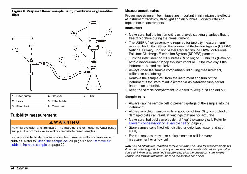
Figure 6 Prepare filtered sample using membrane or glass-fiberfilter
1 Filter pump 4 Stopper 7 Filter
2 Hose 5 Filter holder
3 Filter flask 6 Tweezers
Turbidity measurement
W A R N I N G Potential explosion and fire hazard. This instrument is for measuring water basedsamples. Do not measure solvent or combustible based samples.
For accurate turbidity readings use clean sample cells and remove airbubbles. Refer to Clean the sample cell on page 17 and Remove airbubbles from the sample on page 22.
Measurement notesProper measurement techniques are important in minimizing the effectsof instrument variation, stray light and air bubbles. For accurate andrepeatable measurements:Instrument
• Make sure that the instrument is on a level, stationary surface that isfree of vibration during the measurement.
• The USEPA filter assembly is required for turbidity measurementsreported for United States Environmental Protection Agency (USEPA),National Primary Drinking Water Regulations (NPDWR) or NationalPollutant Discharge Elimination System (NPDES) permits.
• Turn the instrument on 30 minutes (Ratio on) or 60 minutes (Ratio off)before measurement. Keep the instrument on 24 hours a day if theinstrument is used regularly.
• Always close the sample compartment lid during measurement,calibration and storage.
• Remove the sample cell from the instrument and turn off theinstrument if the instrument is stored for an extended time period(more than a month).
• Keep the sample compartment lid closed to keep dust and dirt out.
Sample cells
• Always cap the sample cell to prevent spillage of the sample into theinstrument.
• Always use clean sample cells in good condition. Dirty, scratched ordamaged cells can result in readings that are not accurate.
• Make sure that cold samples do not “fog” the sample cell. Refer to Prevent condensation on a sample cell on page 23.
• Store sample cells filled with distilled or deionized water and captightly.
• For the best accuracy, use a single sample cell for everymeasurement or a flow cell.
Note: As an alternative, matched sample cells may be used for measurements butdo not provide as good of accuracy or precision as a single indexed sample cell orflow cell. When using matched sample cells, align the orientation mark on thesample cell with the reference mark on the sample cell holder.
24 English
Measurement
• Measure samples immediately to prevent temperature changes andsettling. Before a measurement is taken, always make sure that thesample is homogeneous throughout.
• Avoid sample dilution when possible.• Avoid instrument operation in direct sunlight.
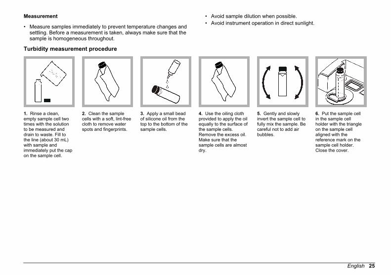
Turbidity measurement procedure
1. Rinse a clean,empty sample cell twotimes with the solutionto be measured anddrain to waste. Fill tothe line (about 30 mL)with sample andimmediately put the capon the sample cell.
2. Clean the samplecells with a soft, lint-freecloth to remove waterspots and fingerprints.
3. Apply a small beadof silicone oil from thetop to the bottom of thesample cells.
4. Use the oiling clothprovided to apply the oilequally to the surface ofthe sample cells.Remove the excess oil.Make sure that thesample cells are almostdry.
5. Gently and slowlyinvert the sample cell tofully mix the sample. Becareful not to add airbubbles.
6. Put the sample cellin the sample cellholder with the triangleon the sample cellaligned with thereference mark on thesample cell holder.Close the cover.
English 25

7. Read and record thevalue when stable.Note: To send (viaRS232) a measurementrecord, push PRINT.
Measurement techniquesMeasurements may be made with different operation mode settings andoptional accessories.Calibrate the instrument whenever the sample cell pathlength ischanged.
Manual or automatic rangingThe manufacturer recommends that ranging be set to automatic for mostmeasurements.The setting can be changed at any time during sample measurement.Push RANGE repeatedly to step the instrument from automatic rangingto manual ranging and then scroll through the manual range settings.The Manual Range light turns on when manual ranging is selected. TheAuto Range light turns on when automatic ranging is selected.Notes:
• When manual ranging is selected, the display flashes all 9s when thesample being measured is greater than the selected range. Thedisplay flashes all 0s when the sample measured is less than theselected range.
• When automatic ranging is selected, the display flashes 9s when thesample is greater than the maximum range of the instrument. The
display flashes 9s when Ratio is off and the measurement is greaterthan 40 NTUs (268 nephelos or 9.8 EBCs). Turn Ratio on to increasethe range. Refer to Measure over-range samples on page 23.
• When automatic ranging is selected, the display flashes all 0s whenthe measurement is less than the range of the instrument or anegative value. Calibrate the instrument.
Signal averaging on or offSignal averaging corrects for reading fluctuations that are caused byrandom drifting particles in the sample. When signal averaging is on, anaverage reading is calculated every 3 seconds and shown on thedisplay.The last ten measurements are used to calculate the averagereading.The manufacturer recommends that signal averaging be on for mostmeasurements.Push SIGNAL AVG to turn signal averaging on or off. The SIGNAL AVGlight turns on when signal averaging is on.Push ENTER when signal averaging is on to erase data in the signalaveraging buffer and provide an immediate update on the display asnecessary. This is especially useful when measuring samples with largedifferences in turbidity.
26 English

Ratio on or offRatio on provides very good linearity, calibration stability and a widemeasurement range. Ratio on helps correct for interference when coloris present in the sample that absorbs at the wavelength of incident light.The manufacturer recommends that Ratio on be used for mostmeasurements. Ratio must be on to measure samples greater than40 NTUs (268 nephelos or 9.8 EBCs).Push RATIO to turn Ratio on or off. The Ratio light is on when Ratio ison.Notes:
• If the sample being measured is greater than 40 NTU (or equivalent)and Ratio is off, the display will show 9s and the RATIO light will flash.Push RATIO to turn Ratio on and remove the over-range condition.
• Measurements with Ratio on and measurements with Ratio off arealmost the same for turbidity measurements that are less than 40 NTUif interferences caused by color or light absorbing particles are notpresent.
Using the air purge systemThe air purge system is used to keep condensation off the externalsurface of the sample cell when cold samples are measured.The air purge system pushes dry air through the optical compartment tokeep the outside the sample cell dry. The connection is made at the airpurge fitting on the back of the instrument Figure 2 on page 8.Use dry nitrogen or instrument grade air (ANSI MC 11.1, 1975) at nogreater than 138 kPa (20 psig). The manufacturer recommends an airconsumption rate of 3 to 10 SCFH (standard cubic feet/hour).When the sample temperature is about or less than 2 °C (35 °F), use adesiccant dryer and particle filter to make sure that the dew point of theair purge is less than the sample temperature. The air dryer containssilica gel desiccant that turns pink. Replace the desiccant when it turnspink.If only shop air is available, use a coalescing filter with an automaticdrain and a dryer and particle filter to get instrument quality air. Use acoalescing filter that typically operates for greater than 2000 hours.Replace the particle filter when the air dryer is replaced.
Figure 7 and Figure 8 show the methods for connecting the two types ofair supply to the instrument.Note: The dryer and filter are not necessary if dry nitrogen is used.
Figure 7 Instrument quality air
1 Particle filter (Balston DFU 9933-05-BQ or equivalent)
3 Pressure regulator
2 Air dryer (Balston DAU 9933-05-101 or equivalent)
4 Instrument air
Figure 8 Standard shop air
1 Particle filter 5 Filter (Balston 100-12-BX orequivalent)
2 Air dryer 6 Auto drain (Balston 20-105 orequivalent)
3 Coalescing filter/regulator (0–30 psig)
7 Filter housing (BalstonFR-920-30 or equivalent)
4 Shop air
English 27

Using a flow cell
C A U T I O N Do not use a flow cell with flammable samples or those that containhydrocarbons, solvents, concentrated acids or concentrated bases that maydamage wetted parts of the cells. Conduct tests before use of flow cells if samplecompatibility is not known.
Note: Do not use a high pressure flow cell kit with this instrument.
Use a flow cell to increase the speed, accuracy and reproducibility ofmeasurement. The manufacturer especially recommends using a flowcell for low turbidity measurements.
Install a flow cell
1. Fully clean and assemble the flow cell, tubing and stand. Refer to Clean a flow cell assembly on page 28 and the user instructionsprovided with the flow cell.
2. Fill the flow cell and tubing with water and make sure that there areno leaks or air bubbles.Note: Air bubbles collect in areas that are not cleaned fully.
3. Clean the exterior surface of the flow cell with a soft, lint-free cloth toremove water spots and fingerprints.
4. Apply a small bead of silicone oil from the top to the bottom of theflow cell.Note: Use only the provided silicone oil. This silicone oil has the samerefractive index as the flow cell glass and masks minor glass scratches.
5. Use the oiling cloth provided to apply the oil equally to the surface ofthe flow cell. Remove the excess oil. Make sure that the flow cell isalmost dry.Note: Put the oiling cloth in a plastic storage bag to keep the cloth clean.
6. Install the flow cell in the sample cell compartment.7. Push the inlet and outlet tubes in the slots on the top of the
instrument enclosure so the sample cell cover can be installed. Referto the user instructions.
8. Put the flow-cell light cover over the flow cell.Note: The standard sample cell cover of the instrument does not close whenthe flow cell is installed.
Clean a flow cell assembly
1. Disassemble the flow cell assembly.2. Clean the inside and outside of the glass parts with a laboratory
glass cleaning detergent. Follow with multiple rinses with distilled ordemineralized water.Note: All tubing, flow cells, and caps in the flow cell assembly can also besteam sterilized.
3. If measuring low turbidity samples, clean the inside and outside ofthe glass parts with 1:1 hydrochloric acid and rinse multiple timeswith dilution water.
4. Fill the sample cell with distilled or demineralized water andimmediately put the caps on the sample cell.
5. Clean the inside and outside of the plastic parts and tubing withlaboratory detergent and warm water.Note: At intervals, replace the tubing as contaminants, includingmicrobiological growths, are difficult to remove from the inside surface of thetubing.
6. Air dry the parts after cleaning.
Flow cell maintenance
• Keep all parts of the flow cell assembly clean.• At intervals, replace all the tubing to make sure that the system is
clean. Keep the tubing as short as possible to minimize air locking andlag time of sample flow. Locate the instrument as close to the drain aspossible.
Flow cell operation
• Do not use the flow cell for samples that contain large particles thatmay collect and stop the sample from flowing.
• Slowly put the sample down the interior edge of the inlet reservoir toprevent mixing of the sample, which can cause air bubbles. Airbubbles create a false positive interference in a turbiditymeasurement.
• If bubbles collect in the flow cell, gently tap the flow cell on a softsurface to remove the bubbles. If bubbles continue to collect in the
28 English
flow cell, put the glass flow cell in liquid detergent for 24 hours andthen rinse fully.
• When measuring many samples of different turbidity, measure thesamples in order of the cleanest (lowest turbidity) to the dirtiest(highest turbidity) to prevent contamination from one sample to thenext.
• Do not use greater than the recommended maximum sample pressureof 34 kPa (5 psig).
• Keep the drain tubing below the center line of the instrument. If thewhole 152 cm (60 in.) length of drain tubing is used, make sure thatthe end of the drain tubing is at least 46 cm (18 in.) below the centerline of the instrument.
Flow cell storage
• Install the reservoir cover when the system is not in use to preventcontamination of the system by airborne particles.
• For short-term storage (a few hours), flush the system with distilled ordeionized water and leave the flow cell full of the flush water tominimize air locks and build up of residue on the parts.
• For long-term storage, disassemble, fully clean and air dry all parts.
Using a manual flow cellTo set the flow rate, increase the height of the collection drain assemblyon the support rod to decrease the flow rate. Make sure that the bottomof the collection drain assembly is no lower than 7.5 cm (3 in.) above thesupport stand base.To flush the flow cell, lower the collection drain assembly to the supportstand base to flush the flow cell.
Use a cell adapterMany different test tubes, sample cells and ampules can be used tomeasure samples when a cell adapter is used. Use a cell adapter whenthe test tube, sample cell or ampule is less than 25 mm. Refer to Accessories on page 40 for the available cell adapters.Use only test tubes and sample cells that are free of significantscratches. Clean and apply silicone oil to all sample cells, test tubes andampules used with the cell adapters. Refer to Clean the sample cellon page 17.
Note: Performance specifications may be different than shown in Specificationson page 5 when test tubes, sample cells or ampules less than 25 mm are used.
Use a cell adapter when:
• Only a small quantity of sample is available.• The sample to be measured is in an ampule that cannot be opened.
Refer to Table 3 for minimum sample sizes.
Table 3 Minimum sample sizes
Test tube size Sample
12 mm 2.5 mL
13 mm 3.5 mL
16 mm 5 mL
19 mm 7 mL
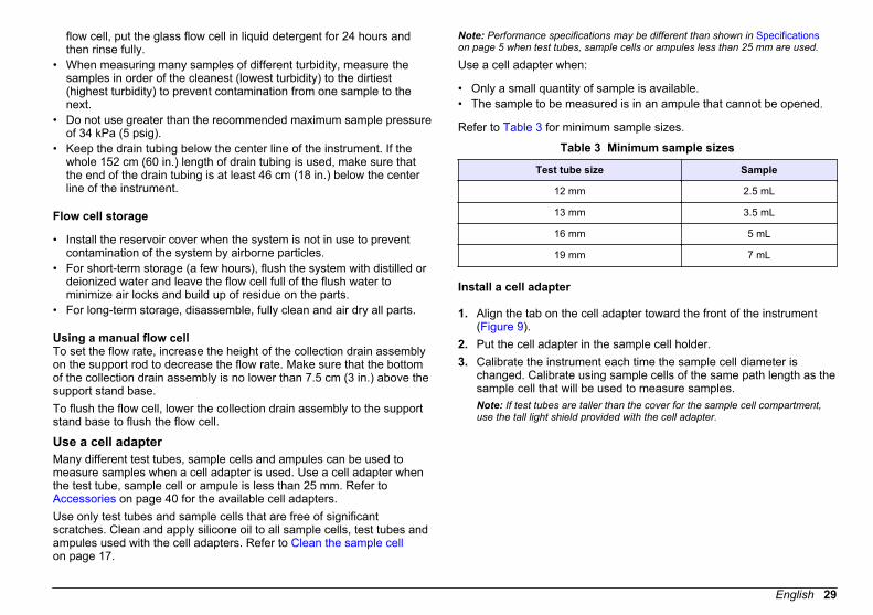
Install a cell adapter
1. Align the tab on the cell adapter toward the front of the instrument(Figure 9).
2. Put the cell adapter in the sample cell holder.3. Calibrate the instrument each time the sample cell diameter is
changed. Calibrate using sample cells of the same path length as thesample cell that will be used to measure samples.Note: If test tubes are taller than the cover for the sample cell compartment,use the tall light shield provided with the cell adapter.
English 29

Figure 9 Install a cell adapter
Remove a cell adapter
1. Carefully pull the cell adapter up until it is half out of the sample cellholder.
2. Slowly turn the cell adapter 90 degrees counter-clockwise.3. Pull the cell adapter up to remove it.
N O T I C E Do not force the cell adapter out of the instrument as serious damage canoccur.
Connect to a printer or computerUse the serial interface (RS232) connector on the back of the instrumentto transmit data from the instrument to a printer or a serialcommunication port on a computer. Refer to Figure 2 on page 8.To connect a serial printer to the instrument, use a printer cableassembly that is terminated with a standard 25-pin D connector. A serial-to-parallel converter can be used to print to a parallel printer. Data istransmitted to a printer as a 39-character string plus the line feed andcarriage return.
To connect a computer to the instrument, use a serial communicationcable with a DB9 connector.Note: Use of the specified cable or equivalent is mandatory for CE compliance (ashielded cable assembly must be used).
Configure the printer output
1. Push and hold down the right arrow key for 3 seconds.2. Select 01 using the arrow keys.3. Push ENTER.4. Use the arrow keys to change the value—SL Pr (slow print,
2.5 second delay) or FS Pr (fast print).5. Push ENTER.
Configure the RS232 connection
1. Push SETUP. The SETUP light turns on.2. Use the arrow keys to select an option:
Option Description
10 Sets the baud rate (default=1200).
11 Sets the character length (default=8).
12 Sets the stop bit (default=1).
13 Sets the parity select (default=NONE).
3. Push ENTER.4. Use the arrow keys to change the value.5. Push ENTER.6. Push SETUP.
Configure a Citizen Model iDP 562RSL II printerThe Citizen Model iDP 562RSL II printer requires configuration forcompatibility with the 2100N turbidimeter. Set the switches and jumperpositions on the Citizen printer board as shown in Figure 10 and Table 4.
30 English

1. Set switches 1, 2, 3, 4, 5 and 8 to OFF.2. Set switches 6, 7, 9 and 10 to ON. Switch 9 and 10 set to ON sets a
1200 baud rate.3. Refer to Setting of Preset Jumper in the Citizen Printer Manual.
Figure 10 Citizen printer switch configuration
Table 4 Dip switch settings for the Citizen printer
USA Germany France UK
Foreign character selection DSW1-4 Off Off On On
DSW1-5 Off On Off On
Odd Even No Check
Parity check DSW1-6 Off On Off On
DSW1-7 Off Off On On
Data DSW1-8 On = 7 bit Off = 8 bit
9600 4800 2400 1200
Baud rate DSW1-9 Off Off On On
DSW1-10 Off On Off On
Computer (RS232) commandsA communication program (i.e., such as Window Terminal or ProCommPlus) is recommended for computer operation of the instrument.Configure the communication program to the RS232 connection settings.Refer to Configure the RS232 connection on page 30.
Table 5 shows the RS232 command set for the instrument.
Table 5 RS232 command set
Command Description
VAL Gets the current measurement with the measurement units.
LST Gets the calibration standards and coefficients.
DAT Gets the current date.To change the date, enter DAT=MM/DD/YY (MM=month, DD=day,YY=year), then push Enter.
TIM Gets the current time in 24-hour format.To change the time, enter TIM=HH:MM (HH=hour, MM=minutes),then push Enter.
RMN Gets the recorder minimum value.To change the recorder minimum value, enter RMN=XXXXX(XXXXX=a number, minimum value=0), then push Enter.
RMX Gets the recorder maximum value.To change the recorder maximum value, enter RMX=XXXXX(XXXXX=a number, maximum value=10,000), then push Enter.
RTN Gets the recorder trim minimum value.To change the recorder minimum value, enter RTN=XXXXX(XXXXX=a number, minimum value=200), then push Enter.
RTX Gets the recorder trim maximum value.To change the recorder maximum value, enter RTX=XXXX(XXXX=a number, maximum value=4800), then push Enter.
SAV Gets the signal average buffer size.To change the signal average buffer size, enter SAV=XX (XX=anumber, maximum value=15, default=10), then push Enter.
English 31

Advanced operation
Calibrate the turbidimeter with formazin standardsThe instrument may be calibrated using prepared formazin standardsmade from 4000-NTU formazin stock solution. Refer to Accessorieson page 40.Note: Use recently prepared formazin standards to get the accuracy specificationsfor turbidity in Specifications on page 5.
Prepare formazin standardsFor the best accuracy and long-term data comparability, use formazinstock solution from Hach to make formazin standards.Note: As an alternative, a 4000-NTU formazin stock solution that is prepared bythe user may be used to make formazin standards. Refer to Making 4000-NTUformazin stock solution on page 35.
Prepare formazin standards immediately before calibration in anenvironment that is at the same ambient temperature as the instrument.Discard after use.Refer to Table 6 for the procedures to make the recommendedcalibration standards.
Table 6 Formazin standard preparation
Standard Step 1 Step 2 Step 3
20 NTU Add 100 mL of dilutionwater to a clean 200-mL Class A volumetricflask. Refer to Preparedilution wateron page 21.
With a TenSette®Pipet, add 1.00 mL ofwell-mixed 4000-NTU formazin stocksolution to the 200-mL flask.
Dilute to the markwith dilution water.Stopper and mix.
Table 6 Formazin standard preparation (continued)
Standard Step 1 Step 2 Step 3
200 NTU Add 50 mL of dilutionwater to a clean 100-mL class A volumetricflask.
With a TenSette1
Pipet, add 5.00 mL ofwell-mixed 4000-NTU formazin stocksolution to the 100-mL flask.
Dilute to the markwith dilution water.Stopper and mix.
1000 NTU Add 50 mL of dilutionwater to a clean 100-mL class A volumetricflask.
With a TenSette1
Pipet, add 25.00 mLof well-mixed 4000-NTU formazin stocksolution to the 100-mL flask.
Dilute to the markwith dilution water.Stopper and mix.
4000 NTU Rinse a clean samplecell two times withwell-mixed 4000-NTUformazin stocksolution. Put about30 mL of 4000-NTUformazin stocksolution in the samplecell. No dilution isnecessary.
— —
1 A class A volumetric pipet may be used in place of a TenSette Pipet.
Calibration notes
• Make sure that the instrument is in the same ambient conditions aswhere it is used.
• Make sure that the standards are at the same ambient temperature asthe instrument before use.
• Use only the provided silicone oil. This silicone oil has the samerefractive index as the vial glass and masks minor glass differencesand scratches.
• Store the oiling cloth in a plastic storage bag to keep the cloth clean.• If power is lost during calibration, the new calibration data is lost and
the last calibration data is used. To exit a calibration and not save thenew values, push UNITS/Exit.
32 English

• In Calibration mode, automatic range and signal averaging on areselected. When calibration is completed, all operational modes goback to the last settings.
• All nephelometric (turbidity units of measure) calibrations are done atthe same time.
• Ratio-on and Ratio-off calibration data is measured and recorded atthe same time.
• Clean the USEPA filter assembly before doing a primary calibration,or at least every 3 months (which is the USEPA-recommendedprimary calibration interval).
Formazin calibration procedureFor the best accuracy, use four matched sample cells or the same sample cell for all measurements during calibration. Refer to Matching sample cellson page 20.
1. Remove the filterassembly. Refer to Change the filterassembly on page 36.
2. Clean and inspectthe lens of the USEPAfilter assembly. Refer to Clean the filterassembly on page 36.
3. Hold the tab of theUSEPA filter assemblyso that the arrows pointtoward the front of theinstrument. Push thefilter assembly fully intothe housing.
4. Push CAL.The S0 light turns on.The NTU value of thedilution water used inthe last calibration isshown.
5. Rinse a cleansample cell two timeswith dilution water. Fillthe sample cell to theline (about 30 mL) withdilution water andimmediately put the capon the sample cell. Usethe same dilution waterthat was used toprepare the formazinstandards.
6. Clean the samplecell with a soft, lint-freecloth to remove waterspots and fingerprints.Do not invert thesample cell.
English 33

7. Apply a small beadof silicone oil from thetop to the bottom of thesample cell.
8. Use the oiling clothprovided to apply the oilequally to the surface ofthe sample cell.Remove the excess oil.Make sure that thesample cell is almostdry.
9. Put the sample cellin the sample cellholder with the triangleon the sample cellaligned with thereference mark on thesample cell holder.Close the cover.
10. Push ENTER.The instrument displaycounts down from 60 to0, and then measuresthe standard.The instrument showsthe next expectedstandard (e.g., 20.00).The S1 light turns on.
11. Remove thesample cell from thesample cell holder.
12. Do steps 5–11 forthe other formazinstandards (from lowestto highest NTUstandard). Mix eachformazin standard welland rinse the samplecell two times withformazin standardbefore the sample cellis filled.The S0 light turns onafter the last samplecell is measured.
13. Push CAL.The instrument savesthe new calibration dataand goes back toMeasurement mode.
34 English

Making 4000-NTU formazin stock solution
W A R N I N G Chemical exposure hazard. Obey laboratory safety procedures and wear all ofthe personal protective equipment appropriate to the chemicals that are handled.Refer to the current material safety data sheets (MSDS) for safety protocols.
Note: Making formazin stock solution from raw materials is not recommended.Preparation of formazin stock solution is temperature and technique sensitive. UseHach formazin stock solution to get the best instrument performance and analyticalstandard accuracy.
1. Dissolve 5.000 grams of reagent grade hydrazine sulfate ((NH2)2–H4H2SO4) in about 400 mL of demineralized water.
2. Dissolve 50.000 grams of reagent grade hexamethylenetetramine inabout 400 mL of demineralized water.
3. Quantitatively, put the two solutions in a 1-liter volumetric flask, anddilute to volume with demineralized water. Mix fully.
4. Let the solution stand for 48 hours at 25 ± 1 °C (77 ± 1 °F).
Calibrate the turbidimeter with user-selected formazinstandardsThe instrument may be calibrated using user-selected values of formazinstandards.Calibration with user-selected values of formazin standards is doneusing the same method that is used to calibrate the instrument withrecommended formazin standards with two differences:
• The prepared formazin standards used are user-selected standardsand not the recommended standards. Refer to Prepare formazinstandards – user selected on page 35.
• The calibration points that are shown on the display must be changedas they occur so they agree with the turbidity of the user-definedstandards. Refer to Change the calibration points on page 35.
Note: Unknown performance may occur if standards other than the recommendedcalibration points are used. The recommended calibration points (< 0.1, 20, 200,1000 and 4000 NTU) provide the best calibration accuracy. Refer to Applicationnote 128, Calibration Methods for Low-Level Turbidity Measurement.
Prepare formazin standards – user selectedUser-selected values of formazin standards are prepared using thesame method that is used to prepare the recommended formazinstandards. Refer to Prepare formazin standards on page 32.Prepare user-selected values of formazin standards to span the entirerange of the instrument. Four standards are necessary. Suggestedstandards are in the range of:
• 10–30 NTU• 180–220 NTU• 900–1000 NTU• 4000 NTU
Formazin standards greater than 80 NTU must have a difference of atleast 60 NTU.
Change the calibration pointsWhen using user-selected values of formazin standards duringcalibration, change the calibration points that are shown on the displayas they occur. Change the calibration points so that they agree with theturbidity of the user-defined values.For example: A 25-NTU standard is put in the sample cell holderinstead of the recommended 20-NTU standard during calibration.Change the "20.000" on the display to "25.000" before pushing ENTERto start the measurement.To change the value on the display during calibration:
1. Push the right arrow key. The decimal point flashes.2. Push the right arrow key to move the cursor to the next position.3. Push ENTER to accept the new cursor position.4. Use the up and down arrow keys to change the number on the
display.5. Do steps 2–4 again if necessary to change the other digit.6. Push ENTER to save the change and start the measurement.
English 35

MaintenanceD A N G E R
Multiple hazards. Only qualified personnel must conduct the tasksdescribed in this section of the document.
Clean the instrumentKeep the instrument clean to get continuous and accurate operation.
N O T I C E Never use cleaning agents such as turpentine, acetone or similar products toclean the instrument including the keypad.
1. Turn the instrument off and disconnect the power cord.2. Clean the surface of the instrument with a soft, moist cloth and a
weak soap solution.3. Dry the surface of the instrument with a lint-free cloth.
Change the filter assemblyN O T I C E
The filter assembly is fragile and must be handled with care to prevent damage.
1. Hold the tab of the filter assembly and pull straight up and out of theinstrument.
2. Store the filter assembly in a clean container.3. Before installation, clean the lens of the filter assembly. Refer to
Clean the filter assembly on page 36.4. Hold the tab of the filter assembly with the arrows pointing toward the
front of the instrument.5. Push the filter assembly fully into the housing.
Clean the filter assemblyNote: Be careful not to push the lens out of the filter assembly.
1. Clean both sides of the lens of the filter assembly with glass cleaner,lens cleaner or isopropyl alcohol, and a cotton-tipped swab or lenstissue.
2. Inspect the filter glass for scratches or other damage.3. If a cloudy circle is seen around the edge of the filter, the filter
material is delaminating. Replace the filter assembly.
Replace the lamp
C A U T I O N Wear protective eye wear when the lamp is turned on and the lamp cover isremoved.
C A U T I O N Burn hazard. The lamp must be cool before removal from the instrument.
Notes:
• Replace the lamp with the same size, style and electrical rating(4708900). Refer to Replacement parts and accessorieson page 40.
• Do not touch the lamp as oil from skin will damage the lamp. Cleanthe lamp with alcohol as necessary.
• Either lamp lead can be put in either terminal block position.• Turn the instrument on 30 minutes (Ratio on) or 60 minutes (Ratio off)
before measurement or calibration.• Calibrate the instrument after the lamp is replaced.
To remove the lamp, refer to the illustrated steps.To install the lamp, do the illustrated steps in the opposite direction.
36 English

1
English 37
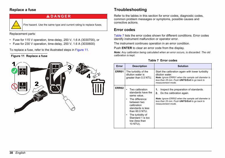
Replace a fuse
D A N G E R
Fire hazard. Use the same type and current rating to replace fuses.
Replacement parts:
• Fuse for 115 V operation, time-delay, 250 V, 1.6 A (3030700), or• Fuse for 230 V operation, time-delay, 250 V, 1.6 A (3030600)
To replace a fuse, refer to the illustrated steps in Figure 11.
Figure 11 Replace a fuse
TroubleshootingRefer to the tables in this section for error codes, diagnostic codes,common problem messages or symptoms, possible causes andcorrective actions.
Error codesTable 7 lists the error codes shown for different conditions. Error codesidentify instrument malfunction or operator error.The instrument continues operation in an error condition.Push ENTER to clear an error code from the display.Note: Any calibration being calculated when an error occurs, is discarded. The oldcalibration is kept.
Table 7 Error codes
Error Description Solution
ERR01 The turbidity of thedilution water isgreater than 0.5 NTU.
Start the calibration again with lower turbiditydilution water.Note: Ignore ERR01 when the sample cell diameter isless than 25 mm. Push UNITS/Exit to go back tomeasurement mode.
ERR02 • Two calibrationstandards have thesame value.
• The differencebetween twocalibrationstandards is lessthan 60.0 NTU.
• The turbidity ofStandard 1 is toolow (less than10 NTU).
1. Inspect the preparation of standards.2. Do the calibration again.
Note: Ignore ERR02 when the sample cell diameter isless than 25 mm. Push UNITS/Exit to go back tomeasurement mode.
38 English

Table 7 Error codes (continued)
Error Description Solution
ERR03 Low light error 1. Put the sample in the instrument again.2. Make sure that the lamp light is on.3. Make sure that an object is not in the light
path.4. Do sample dilution if necessary.
Note: If this error occurs when a filter assembly otherthan the USEPA filter assembly is installed, the filterassembly should not be used for turbiditymeasurements.
ERR04 Memory malfunction 1. Turn the instrument off and then back on.2. Contact Technical Support if the error
occurs again.
ERR05 A/D is over the range 1. Make sure that the light shield is closed.2. Contact Customer Service if necessary.
ERR06 A/D is under the range 1. Make sure that no object is in the lightpath.
2. Contact Customer Service if necessary.
ERR07 Light leak 1. Make sure that the cover for the samplecell compartment is closed.
2. Turn the instrument off and then back on.
ERR09 Printer time out error 1. Make sure that the external printer isconnected correctly.
2. Make sure that the external printer isselected (online).
Table 7 Error codes (continued)
Error Description Solution
ERR10 System voltage out ofrange 1. Turn the instrument off and then back on.
2. Contact Customer Service if the erroroccurs again.
ERR11 System loop test error 1. Turn the instrument off and then back on.2. Contact Customer Service if the error
occurs again.
Diagnostic codesTable 8 lists the diagnostic codes that are used to get information aboutinstrument operation when instrument operation is in doubt.To do a diagnostic test:
1. Push and hold down the right arrow key for 3 seconds.2. Use the arrow keys to enter a diagnostic code.3. Push ENTER to show the diagnostic value.4. Push UNITS/Exit to go back to Measurement mode.
Note: To print a diagnostic report, hold down PRINT, then turn the instrument on.
Table 8 Diagnostic codes
Code Display Description
21 Pr In Printer test
22 Test results are shown. Display test
23 Test results are shown. Keyboard test
24 Test results are shown. Memory test
Delete calibration data
To delete any calibration data entered by the user:
English 39

1. Turn off the instrument.2. Push and hold CAL.3. Turn on the instrument.
The CAL? light flashes. The instrument starts in Calibration mode.4. Calibrate the instrument before use.
Flashing 9sWhen manual ranging is selected, the display will flash all 9s when thesample being measured is greater than the selected range.When automatic ranging is selected, the display will flash 9s when thesample is greater than the maximum range of the instrument. Thedisplay will also flash 9s if Ratio is off and the measurement is greaterthan 40 NTUs (268 nephelos or 9.8 EBCs). Turn Ratio on. Refer to Measure over-range samples on page 23.
Flashing 0sWhen manual ranging is selected, the display will flash all 0s when thesample measured is less than the selected range.When automatic ranging is selected, the display will flash all 0s when themeasurement is less than the range of the instrument or a negativevalue. Calibrate the instrument.
Replacement parts and accessoriesNote: Product and Article numbers may vary for some selling regions. Contact theappropriate distributor or refer to the company website for contact information.
Replacement parts
Description Quantity Item no.
Calibration kit, StablCal®, sealed samplecells (<0.1, 20, 200, 1000 and 4000 NTU) 1 2662105
Cover, sample cell compartment 1 4702500
Cover, lamp access 1 4703200
Dust cover 1 4703000
Replacement parts and accessories (continued)Description Quantity Item no.
Filter assembly, USEPA 1 3031200
Fuse for 115 V operation, time-delay,250 V, 1.6 A, UL/CSA approved 1 3030700
Fuse for 230 V operation, time-delay,250 V, 1.6 A, IEC type, VDE approved 1 3030600
Gelex® secondary turbidity standardizationkit(stray light standard and 0–2, 0–20, 0–200 and 200–4000 NTU)
1 2589000
Lamp replacement kit 1 4708900
Oiling cloth 1 4707600
Power cord, North America, 115 VAC,UL/CSA approved 1 1801000
Power cord, European, 230 VAC, VDEapproved 1 4683600
Sample cells, 30mL, 1 in. round glass 6 2084900
Silicone oil 1 126936
Accessories
Description Quantity Item no.
Calibration kit, StablCal®, 500 mL each(<0.1, 20, 200, 1000 and 4000 NTU)
1 2662110
Calibration kit, StablCal®, 500 mL each(<0.1, 20, 200, 1000 and 4000 NTU)
1 2662100
Cable, computer, DB-9 to DB-9 1 4950200
Cell adapter, 12–13 mm 1 3033400
Cell adapter, 16 mm 1 3033500
40 English

Replacement parts and accessories (continued)Description Quantity Item no.
Cell adapter, 19 mm 1 3033600
Filter disks 10 2323810
Filter, membrane (without pad) 200 1353001
Filter paper, glass fiber, quantitative,47 mm 100 253000
Flow cell kit, manual, low pressure 1 4744900
Flow cell, glass (included with the manualflow cell kit) 1 4709500
Formazin stock solution, 4000 NTU 100 mL 246142
Formazin stock solution, 4000 NTU 500 mL 246149
Pump, vacuum, hand-operated 1 1428300
Pump, vacuum/pressure, 115V, 60 Hz,1.2 cfm 1 2424800
Pump, vacuum/pressure, 220V, 50 Hz,1.2 cfm 1 2824802
Sample degassing kit 1 4397500
Sample degassing and filtration kit 1 4397510
0.1 NTU, StablCal™ low-level turbidityverification standards (not for instrumentcalibration)
100 mL 2723342
0.3 NTU, StablCal™ low-level turbidityverification standards (not for instrumentcalibration)
100 mL 2697942
0.5 NTU, StablCal™ low-level turbidityverification standards (not for instrumentcalibration)
100 mL 2698042
TenSette® Pipet, 1.0-10.0 mL, 1 1970010
TenSette® Pipet Tips 250 2199725
Replacement parts and accessories (continued)Description Quantity Item no.
Tubing, tygon, ¼-inch OD x 1/16 inch wide,for the manual or automated flow cell 1 ft 4134400
Tubing, tygon, 3/8-inch OD x 1/16 inch wide,for the automated flow cell 1 ft 518137
Tubing, tygon, ½-inch OD x 1/16 inch wide,for the manual flow cell 1 ft 518637
Ultrasonic bath 1 2489500
Volumetric flask, 100 mL, Class A 1 1457442
Volumetric flask, 200 mL, Class A 1 1457445
Optional reagents
Description Quantity Item no.
Hexamethylenetetramine 500 g 187834
Hydrazine sulfate 100 g 74226
English 41

42 English


HACH COMPANY World HeadquartersP.O. Box 389, Loveland, CO 80539-0389 U.S.A.Tel. (970) 669-3050(800) 227-4224 (U.S.A. only)Fax (970) [email protected]
HACH LANGE GMBHWillstätterstraße 11D-40549 Düsseldorf, GermanyTel. +49 (0) 2 11 52 88-320Fax +49 (0) 2 11 52 [email protected]
HACH LANGE Sàrl6, route de Compois1222 VésenazSWITZERLANDTel. +41 22 594 6400Fax +41 22 594 6499
© Hach Company/Hach Lange GmbH, 2012. All rights reserved. Printed in Germany.


