59
User Manual for Robotic Lawnmowers: HRM300 – HRM500 Ver.No. Description of Changes Page No. Date 1 Initial Version December, 2012

User Manual for Robotic Lawnmowers:
HRM300 – HRM500
Ver.No. Description of Changes Page No. Date
1 Initial Version December, 2012
Summary 1 Precautions when using. .......................................................................................................... 3
2 Outline of system ..................................................................................................................... 5
3 Components ............................................................................................................................. 6
4 Preparation before installing software ...................................................................................... 7
4.1 System requirements ........................................................................................................ 7
4.2 Confirm PC environment ................................................................................................... 7
4.2.1 How to check OS, CPU, memory (for Windows 7) ..................................................... 7
4.2.2 How to check free space on the hard disk.................................................................. 8
4.3 Setting up PC ................................................................................................................... 9
4.3.1 Screen Saver ............................................................................................................. 9
4.3.2 Settings for system sleep and system hibernate ...................................................... 10
5 Installing software .................................................................................................................. 13
5.1 Downloading DrH Software for Miimo ............................................................................. 13
5.2 Installing the software ..................................................................................................... 16
6 Communication unit settings .................................................................................................. 21
7 Connecting to the product ...................................................................................................... 22
8 Operation ............................................................................................................................... 29
8.1 Auto Test ........................................................................................................................ 29
8.2 Manual Test .................................................................................................................... 31
8.3 Setting Data .................................................................................................................... 33
8.3.1 SYSTEM SETUP ..................................................................................................... 33
8.3.2 QUICK MODE SETUP ............................................................................................. 35
8.3.3 QUICK MODE SETUP Basic operation ................................................................... 37
8.3.4 CUSTOM MODE SETUP ......................................................................................... 37
8.4 Operating History ............................................................................................................ 40
8.5 Calibration ...................................................................................................................... 42
8.6 Test Trip ......................................................................................................................... 43
8.7 DTC History .................................................................................................................... 44
8.8 Live Data ........................................................................................................................ 45
8.9 Service Report ................................................................................................................ 56
8.10 Links ............................................................................................................................... 59

Introduction Thank you for purchasing Dr.H. Please read these instructions carefully and take care to use Dr. H
properly.
1. It is prohibited to reproduce this user manual in whole or in part without prior consent.
2. The contents and illustrations in this user manual may change without notification.
Trademarks
Windows is the registered trademark of Microsoft Corporation. All other brands or product names are
the trademarks of those companies.
1 Precautions when using.
Please read the following before using Dr. H
Adequate consideration for safety has been taken in regard to this product. However, please make
sure that you only use this product after reading what is written in sections with the mark displayed
below, and in the Warning and Caution sections.
The mark displayed below is to ensure the proper usage of this product to prevent the (unlikely)
occurrence of faults or damage.
Danger
Failure to follow these
instructions may result in
death or serious injury
Warning
There is a possibility of
death or serious injury
should these instructions
not be followed
Caution
Failure to follow these
instructions may result in
injury
Do not disassemble or modify
Do not disassemble or modify the Dr. H unit (communication unit), or the attachments or
any of the optional items. This can cause overheating, burns, electric shock, injury and
malfunction. The warranty shall be invalid if disassembled even just once.

Advice
Handling this product:
Do not expose to water
o The Dr. H unit (communication unit) and USB cables do not conform to waterproof
specifications.
o Do not expose to high temperatures or sea (salty) breeze for extended periods.
Condensation may form inside the unit due to sudden changes in the surrounding
temperature. This may occur, for example, when bringing the product suddenly
from a cold place into a warm room.
Use the optional waterproof box when exposed to splashing water or snowfall. (Refer to P*-
Components)
Do not drop the Dr. H unit (communication unit) or place anything on top of it. This could
damage it or cause it to malfunction.
Do not use the Dr. H unit, attachments or optional goods if dented, cracked, damaged etc.
Connect the end of the cable securely after checking for corrosion or damage to the
connectors on the Dr. H unit. Do not use force to connect or disconnect. This may
damage it or cause it to malfunction.
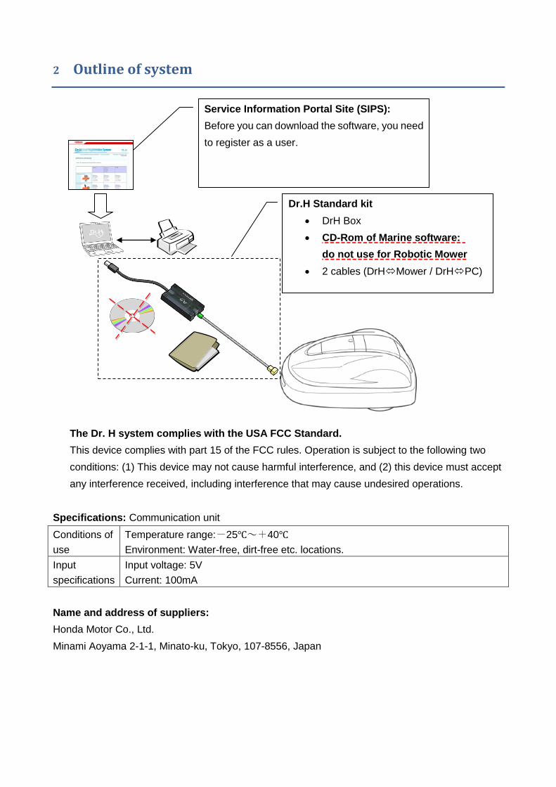
2 Outline of system
The Dr. H system complies with the USA FCC Standard.
This device complies with part 15 of the FCC rules. Operation is subject to the following two
conditions: (1) This device may not cause harmful interference, and (2) this device must accept
any interference received, including interference that may cause undesired operations.
Specifications: Communication unit
Conditions of
use
Temperature range:-25℃~+40℃
Environment: Water-free, dirt-free etc. locations.
Input
specifications
Input voltage: 5V
Current: 100mA
Name and address of suppliers:
Honda Motor Co., Ltd.
Minami Aoyama 2-1-1, Minato-ku, Tokyo, 107-8556, Japan
i-GX
Dr.H Standard kit
DrH Box
CD-Rom of Marine software:
do not use for Robotic Mower
2 cables (DrHMower / DrHPC)
Service Information Portal Site (SIPS):
Before you can download the software, you need
to register as a user.

3 Components
Dr. H standard kit 06398-YH0-010
1.
Interface unit
communication unit connecting
products to PC.
*Do not disassemble.
2.
USB cable
Cable for connecting PC and
communication unit.
3.
DLC harness
Harness for connecting
communication unit to products.
4.
Marine basic software is not
required to use Dr.H for Robotic
Lawnmower. Please do not
install, instead download the
software for Robotic
Lawnmower from SIPS.
5.
Instructions

4 Preparation before installing software
4.1 System requirements
OS Windows XP Service Pack 2 and above, Windows Vista, Windows7
CPU Intel Pentium III 600MHz or AMD Athlon 10 GHz or higher
Memory 512 MB RAM or higher
Port USB port
Disk device CD-ROM drive
Free space in hard disk 1 GB free space
Software framework Microsoft .NET Framework3.5 SP1
* The memory capacity and free space on the hard disk will vary between PCs.
* Using models with only a small amount of free hard disk space can lead to deficient memory or
similar memory problems.
* Operations may be different depending on the model of PC used.
4.2 Confirm PC environment
4.2.1 How to check OS, CPU, memory (for Windows 7)
1- Click “Start”. Right-click “Computer” and click “Properties”

2- Confirm your configuration patches DrH requirements (see ch 4.1)
4.2.2 How to check free space on the hard disk
1. Click “Start” and then click “Computer”.
OS
CPU, Memory
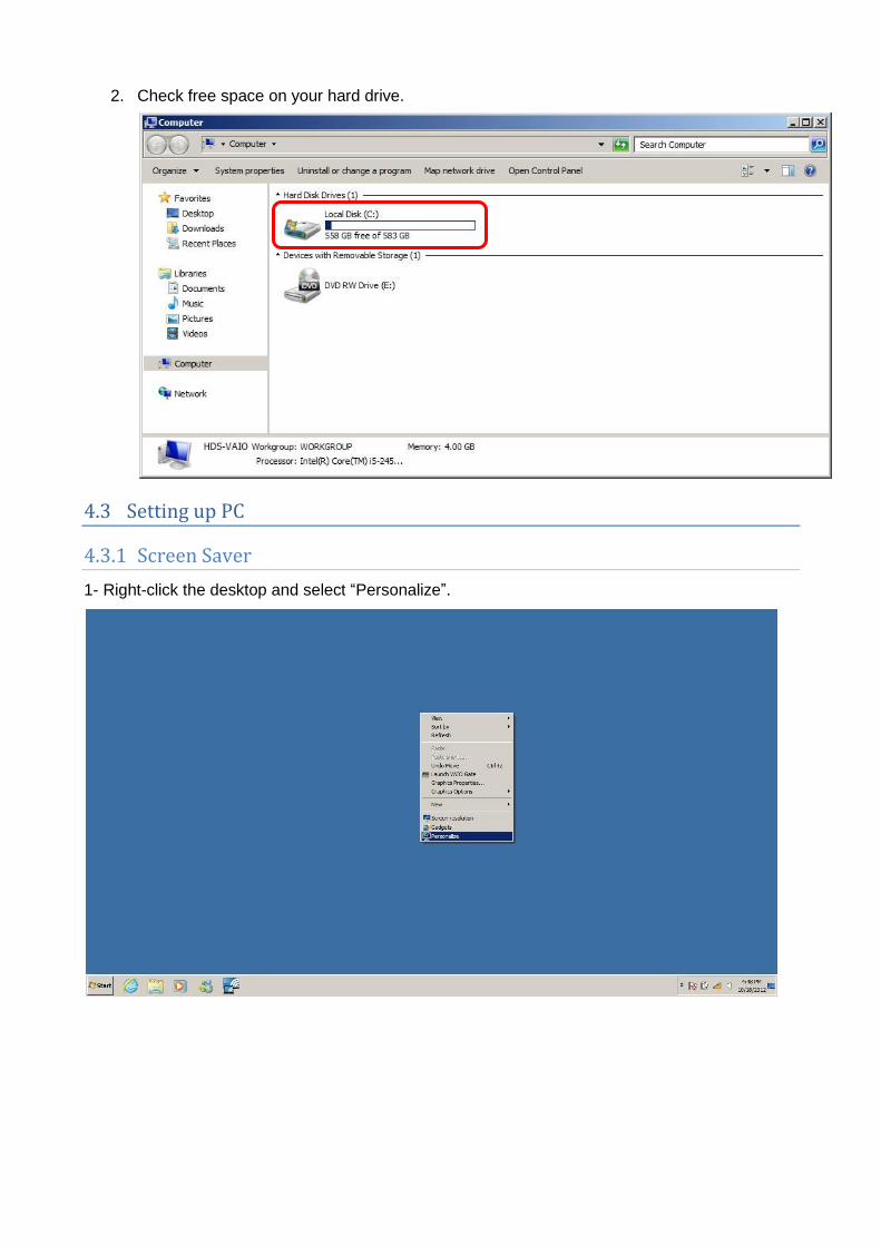
2. Check free space on your hard drive.
4.3 Setting up PC
4.3.1 Screen Saver
1- Right-click the desktop and select “Personalize”.
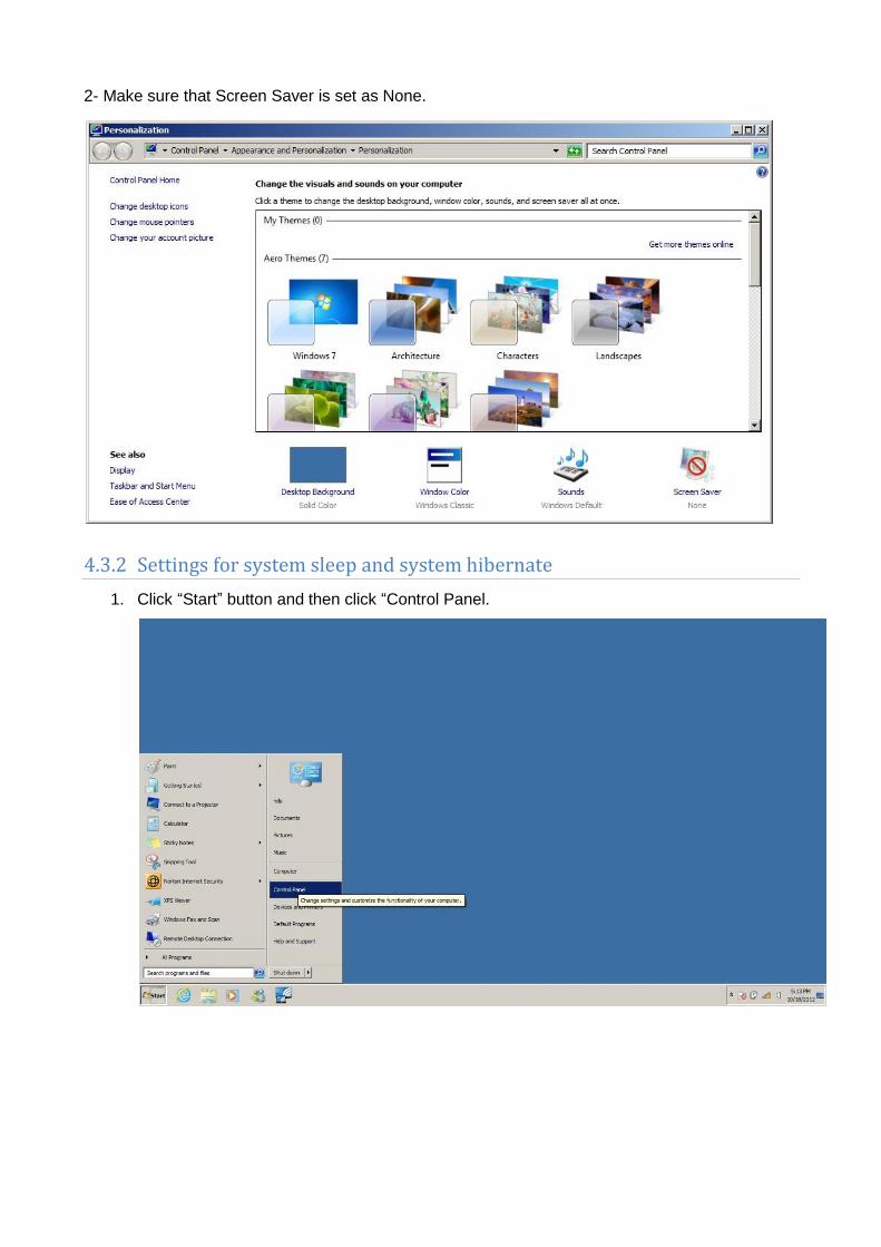
2- Make sure that Screen Saver is set as None.
4.3.2 Settings for system sleep and system hibernate
1. Click “Start” button and then click “Control Panel.

2. Click “System and Security”
3. Click “Power Options”.
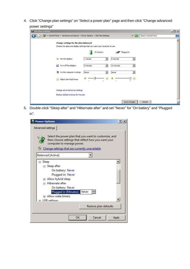
4. Click “Change plan settings” on “Select a power plan” page and then click “Change advanced
power settings”
5. Double-click “Sleep after” and “Hibernate after” and set “Never” for “On battery” and “Plugged
in”.
5 Installing software
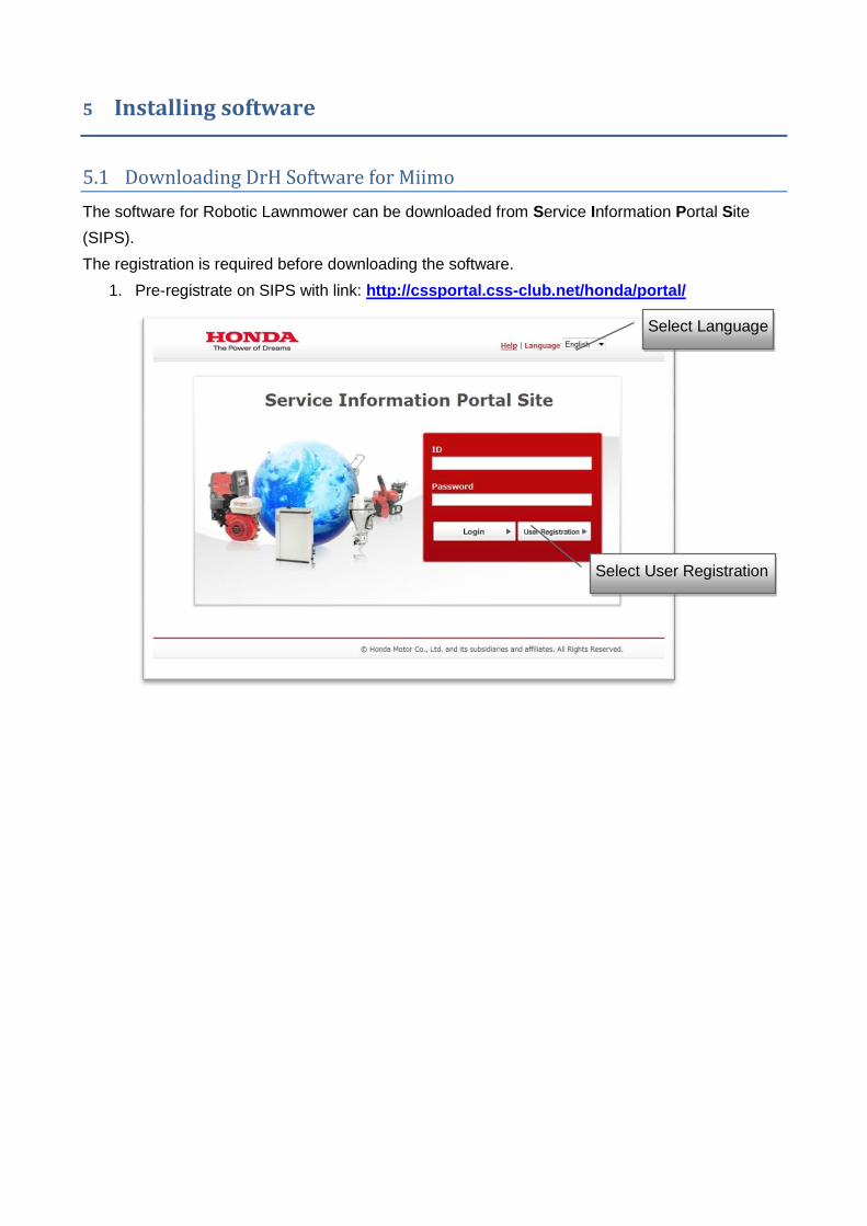
5.1 Downloading DrH Software for Miimo
The software for Robotic Lawnmower can be downloaded from Service Information Portal Site
(SIPS).
The registration is required before downloading the software.
1. Pre-registrate on SIPS with link: http://cssportal.css-club.net/honda/portal/
Select Language
Select User Registration

Advice
Before going further, ensure your e-mail Spam filter is off to receive automatic e-mail reply from
SIPS website.
2. Select “Dr.H” and fill-in the form:
Important: do not use same e-mail address for 2 different users.
3. After confirmation, a code is sent to personal e-mail address to complete registration.

4. Once you received registration confirmation, login with ID and password.
5. Download Dr.H Miimo software and install on computer.

5.2 Installing the software
1- Double-click downloaded software.
2- Click “Next”.

3- Read License Agreement and click “Yes”.
4- Select language(s) to be installed, then click “Next”.
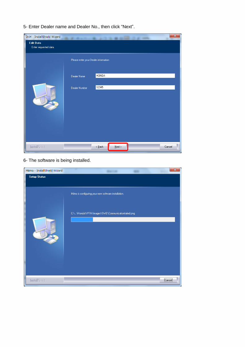
5- Enter Dealer name and Dealer No., then click “Next”.
6- The software is being installed.
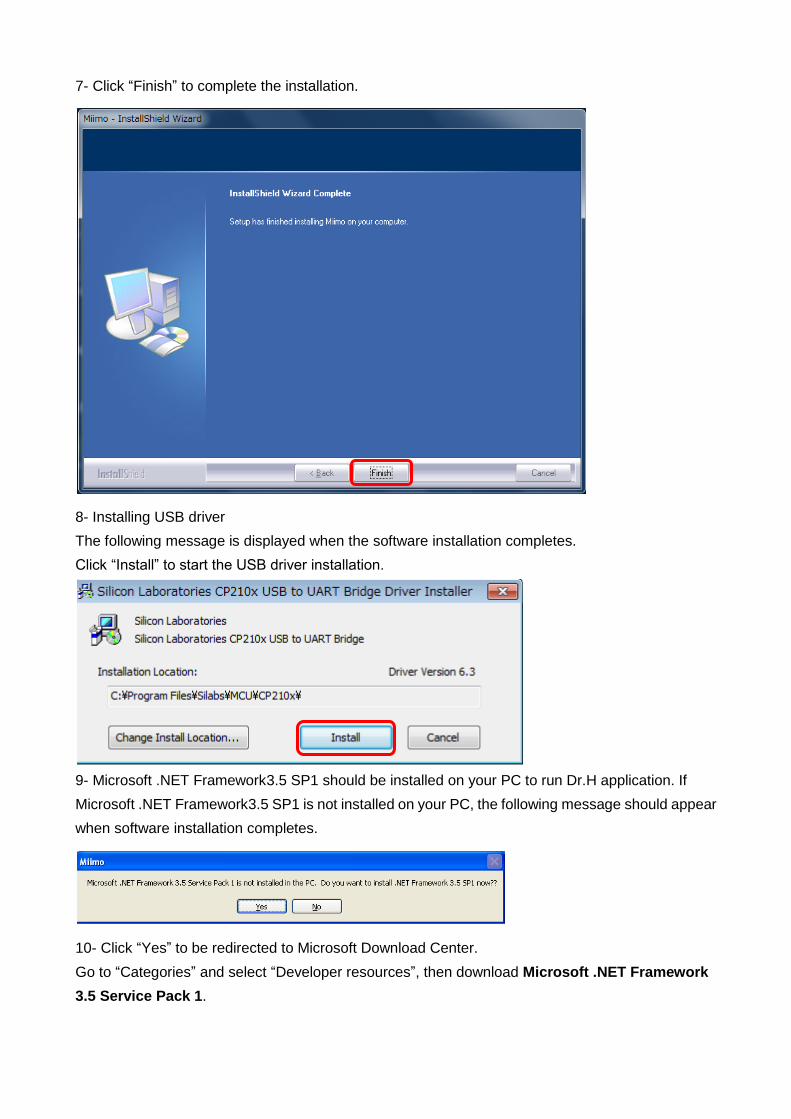
7- Click “Finish” to complete the installation.
8- Installing USB driver
The following message is displayed when the software installation completes.
Click “Install” to start the USB driver installation.
9- Microsoft .NET Framework3.5 SP1 should be installed on your PC to run Dr.H application. If
Microsoft .NET Framework3.5 SP1 is not installed on your PC, the following message should appear
when software installation completes.
10- Click “Yes” to be redirected to Microsoft Download Center.
Go to “Categories” and select “Developer resources”, then download Microsoft .NET Framework
3.5 Service Pack 1.


11- Restart your computer to apply these changes.
6 Communication unit settings
Connect the USB cable and the communication unit to the PC.
The software will be installed automatically.

7 Connecting to the product
1. Connect the communication unit DLC cable to the product's connector (blue).
2. Turn on the mower.
3. Double-click the Dr. H icon on the desktop and start up Dr. H.
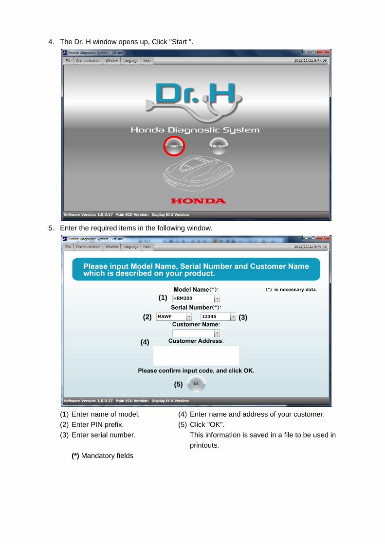
4. The Dr. H window opens up, Click "Start ".
5. Enter the required items in the following window.
(1) Enter name of model.
(2) Enter PIN prefix.
(3) Enter serial number.
(*) Mandatory fields
(4) Enter name and address of your customer.
(5) Click "OK".
This information is saved in a file to be used in
printouts.
(1)
(2) (3)
(4)
(5)

6. Check that there are no problems with the confirm items window that follows, and click "OK".
7. When the communication is successful, the below screen appears.

8. If the USB communication fails, the following window is displayed. The communication port
setting shows "No USB Connection" (1).
9. Check the communication port by following these steps. Select communication setting and
click "Com port setting" (2).
(1)
(2)
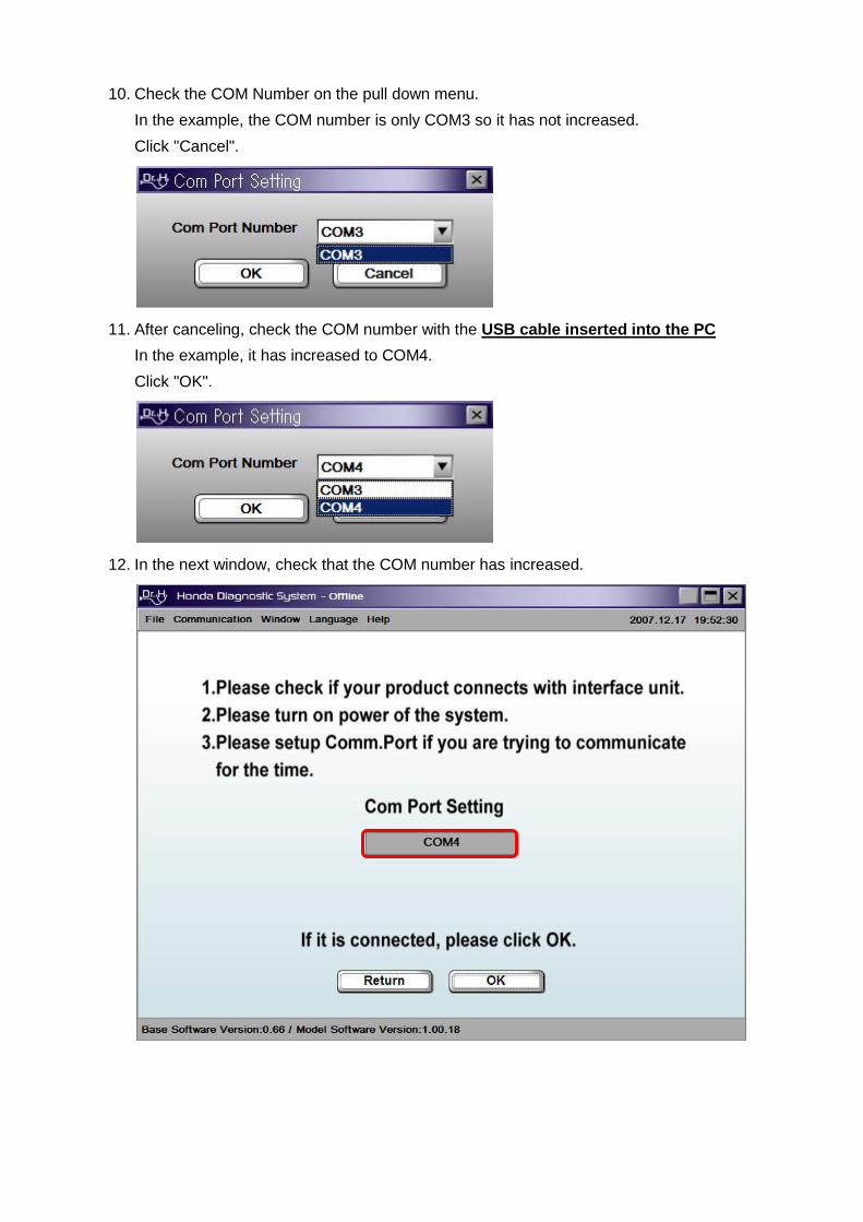
10. Check the COM Number on the pull down menu.
In the example, the COM number is only COM3 so it has not increased.
Click "Cancel".
11. After canceling, check the COM number with the USB cable inserted into the PC
In the example, it has increased to COM4.
Click "OK".
12. In the next window, check that the COM number has increased.

13. When the product is not turned on, the red LED light on the communication unit flashes and
the following message is displayed.
Click "OK".
14. The following window appears. The mark flashes.
15. Check if the ignition switch on the product is on.
16. Check that the communication unit is properly connected.
17. Make sure that the cable connection has not come out and that the connector is fully
attached.

18. When the Communication is successful, the red LED light on the communication unit goes off
and the green LED light comes on. Click "Next".
8 Operation
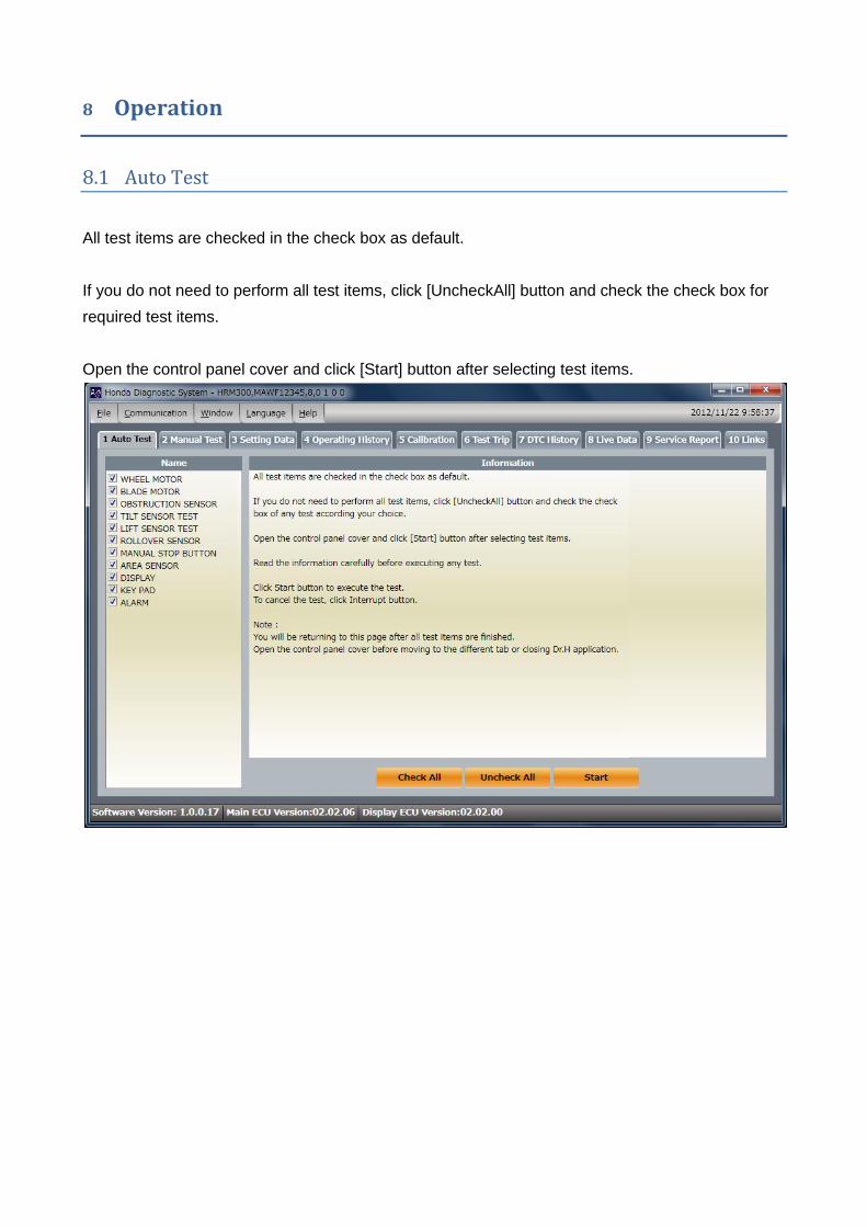
8.1 Auto Test
All test items are checked in the check box as default.
If you do not need to perform all test items, click [UncheckAll] button and check the check box for
required test items.
Open the control panel cover and click [Start] button after selecting test items.

Buttons and Windows
(1) Test Name : Available Test items are listed. Highlighted line shows the test which is
performed.
(2) Start : Clicking this button will start the highlighted test.
(3) Go to Home Page : Clicking this button will return to Auto Test Home Page.
(4) Interrupt : Clicking this button will cancel the current test.
(5) Information : Information describes steps for the test. Read the information carefully before
executing any test.
(6) Parameters : It lists all associated signals with their signal description, signal value and unit
of measure for the signal.
(1)
(2)
(4)
(5)
(6)
(3)

8.2 Manual Test
1- Open the control panel cover and click Start button to go to the Manual Test page.
2-Following screen appears:

Buttons and Windows:
(1) Test Name : Available Test items are
listed. Select the test you wish to
perform in this list.
(2) Start : Clicking this button will start the
test.
(3) Continue Execution : Set "Continue
Execution" ON will disable the timer and
allows you to continue the test as long as
you require.
(4) Go to Home Page : Clicking this button
will return to Auto Test Home Page.
(5) Interrupt : Clicking this button will cancel
the current test.
(6) Information : Information describes steps
for the test. Read the information
carefully before executing any test.
(7) Parameters : It lists all associated
signals with their signal description,
signal value and unit of measure for the
signal.
(1)
(2) (3) (4) (5)
(6)
(7)

8.3 Setting Data
8.3.1 SYSTEM SETUP
Buttons and Windows
1. Setting systems : Available systems for setting are listed.
2. Setting window : Enter new values in Setup column for settings.
3. Information : Information describes steps for the setting.
4. Copy All Settings
To PC : Clicking this button will save all the setting data values except SECURITY and DATE
AND TIME from connected product to a file on your computer.
To Product : Clicking this button will read all values from a file created by [To PC], and then
update connected product with those saved values.
5. Reading : Clicking this button will display the current values in the [Current] column.
6. Setup : Clicking this button will set new values into the mower.
SYSTEM SETUP Basic operation
1. Select a system to check the current setting or to set new values.
2. Click [Reading] button to display the current setting value.
3. Enter new values in Setup column.
4. Click [Setup] button.
5. Click [Reading] to check if new values are displayed in Current column.
Copy All Settings
[Copy All Settings] will allow you to update all setting data values except DATE AND TIME and
SECURITY in the mower with already saved values.
(1)
(2)
(3)
(4) (5) (6)

Saving Setting Data values from the lawnmower
1. Click [To PC] button in [Copy All Settings].
2. Click [Save] (change the file name if required).
3. Click [OK]
Transmit Setting Data values to the lawnmower
1. Click [To Product] button.
2. Select a saved data file and click [Open].
3. Then all setting data values will be transmitted to the lawnmower.
Note: this process can take more than 1 minute.

8.3.2 QUICK MODE SETUP
Buttons and Windows
(1) Week Day Setup : Select Week Day for settings
(2) Timer Setup : Enter Start/End time for Timer 1 (and Timer 2 if required)
Note:
Overnight timer setting is not allowed.
Incorrect setting example:
23:00 - 00:30
Use 24-hour time format
For Timer 2, do not set earlier time than Timer 1.
Incorrect setting example:
Timer 1 17:00 - 18:30
Timer 2 10:00 - 11:00
Ensure to set different time for Timer 1 and Timer 2.
Incorrect setting example:
Timer 1 10:00 – 12:00
Timer 2 11:00 – 13:00
(3) Zone : Enter new values in Setup column for Zone2 settings.
(1)
(2)
(3)

Buttons and Windows
(4) Information : Information describes steps for the setting.
(5) Copy All Settings
To PC : Clicking this button will save all the setting data values except SECURITY and DATE
AND TIME from connected product to a file on your computer.
To Product : Clicking this button will read all values from a file created by [To PC], and then
update connected product with those saved values.
(6) Reset : Clicking this button will reset all values to factory settings in QUICK MODE SETUP.
(7) Reading : Clicking this button will display the current values in the [Current] column.
(8) Setup : Clicking this button will set new values into the mower.
(4)
(5) (6) (7) (8)

8.3.3 QUICK MODE SETUP Basic operation
1. Click [Reading] button to display the current setting value.
2. Select Week day for timers.
3. Enter Start/End time for Timer 1 (and Timer 2 if required)
4. Enter new values for Zone2 in Setup column
5. Click [Setup] button.
6. Click [Reading] to check if Week day and Timers are set correctly and Zone2 new values are
displayed in Current column.
8.3.4 CUSTOM MODE SETUP
8.3.4.1 TIMER
Buttons and Windows
(1) Week Day Setup : Select Week Day for settings
(2) Timer Setup : Enter Start/End time for Timer 1 (and Timer 2 if required) for each selected
Week Day.
(3) Zone : Select Zone for each selected Week Day and Timer 1 (and Timer 2)
(1)
(2)
(3)

Buttons and Windows
(4) Information: Information describes steps for the setting.
(5) Copy All Settings
To PC: Clicking this button will save all the setting data values except SECURITY and DATE
AND TIME from connected product to a file on your computer.
To Product : Clicking this button will read all values from a file created by [To PC], and then
update connected product with those saved values.
(6) CopyQuickSetup : Clicking this button will copy QUICK MODE SETUP setting values to
CUSTOM SETUP.
(7) Reset: Clicking this button will reset all values to factory settings in CUSTOM SETUP –
TIMER.
(8) Reading: Clicking this button will display the current values in the [Current] column.
(9) Setup: Clicking this button will set new values into the mower.
CUSTOM MODE SETUP – TIMER Basic operation
1. Click [Reading] button to display the current setting value.
2. Select Week day.
3. Select Weekday tab to set Timer.
4. Enter Start/End time for Timer 1 (and Timer 2 if required)
5. Select Zone for each selected Week Day and Timer 1 (and Timer 2)
6. Click [Setup] button.
7. Click [Reading] to check if Week day and Timers are set correctly and Zone new values are
displayed in Current column.
(4)
(5) (6) (7) (8) (9)
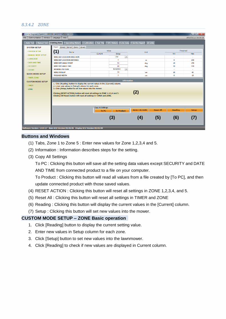
8.3.4.2 ZONE
Buttons and Windows
(1) Tabs, Zone 1 to Zone 5 : Enter new values for Zone 1,2,3,4 and 5.
(2) Information : Information describes steps for the setting.
(3) Copy All Settings
To PC : Clicking this button will save all the setting data values except SECURITY and DATE
AND TIME from connected product to a file on your computer.
To Product : Clicking this button will read all values from a file created by [To PC], and then
update connected product with those saved values.
(4) RESET ACTION : Clicking this button will reset all settings in ZONE 1,2,3,4, and 5.
(5) Reset All : Clicking this button will reset all settings in TIMER and ZONE
(6) Reading : Clicking this button will display the current values in the [Current] column.
(7) Setup : Clicking this button will set new values into the mower.
CUSTOM MODE SETUP – ZONE Basic operation
1. Click [Reading] button to display the current setting value.
2. Enter new values in Setup column for each zone.
3. Click [Setup] button to set new values into the lawnmower.
4. Click [Reading] to check if new values are displayed in Current column.
(1)
(2)
(7) (6) (5) (4) (3)

8.4 Operating History
OPERATING TIME
Clicking [Reading] button will display the total operating time of the mower.
ACTIVATION COUNT :
Clicking [Reading] button will display how many times each sensor is ON.
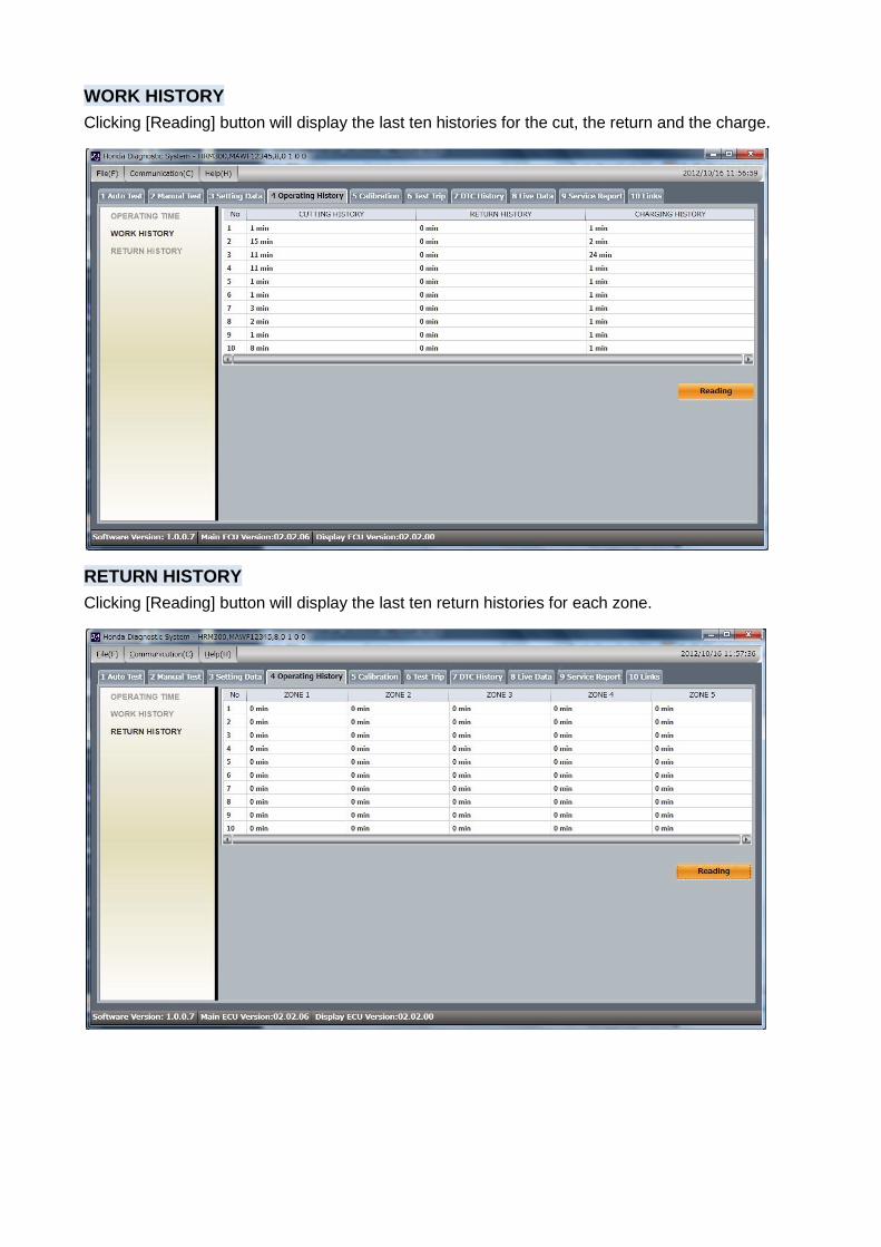
WORK HISTORY
Clicking [Reading] button will display the last ten histories for the cut, the return and the charge.
RETURN HISTORY
Clicking [Reading] button will display the last ten return histories for each zone.
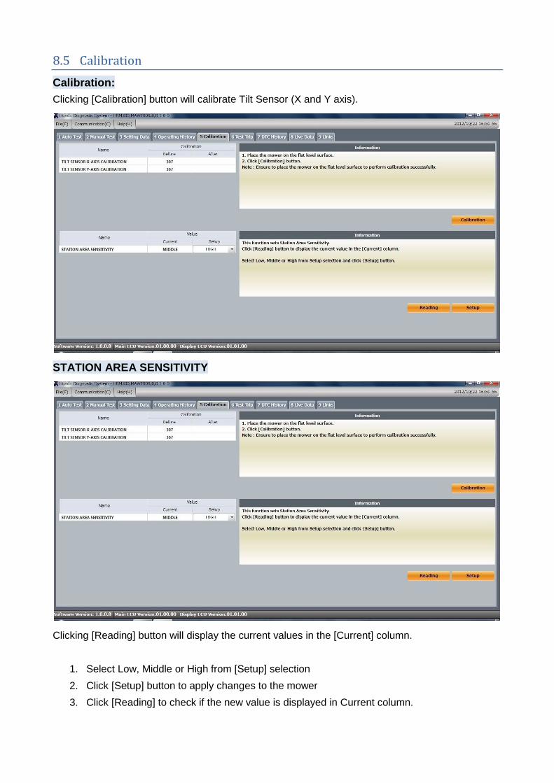
8.5 Calibration
Calibration:
Clicking [Calibration] button will calibrate Tilt Sensor (X and Y axis).
STATION AREA SENSITIVITY
Clicking [Reading] button will display the current values in the [Current] column.
1. Select Low, Middle or High from [Setup] selection
2. Click [Setup] button to apply changes to the mower
3. Click [Reading] to check if the new value is displayed in Current column.

8.6 Test Trip
[Trip] displays the accumulated cutting time, charging time, return time, running time and battery
charge cycles from [Start Date & Time] since last reset.
Clicking [Reading] button will display values in [Value] column.
Clicking [Reset] button will reset all values and will set current date and time in [Start Date &
Time] value column.
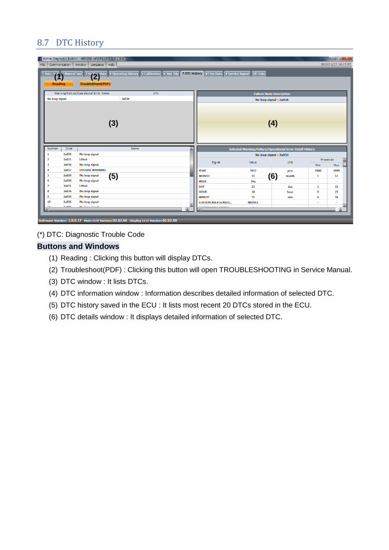
8.7 DTC History
(*) DTC: Diagnostic Trouble Code
Buttons and Windows
(1) Reading : Clicking this button will display DTCs.
(2) Troubleshoot(PDF) : Clicking this button will open TROUBLESHOOTING in Service Manual.
(3) DTC window : It lists DTCs.
(4) DTC information window : Information describes detailed information of selected DTC.
(5) DTC history saved in the ECU : It lists most recent 20 DTCs stored in the ECU.
(6) DTC details window : It displays detailed information of selected DTC.
(1) (2)
(3) (4)
(5) (6)
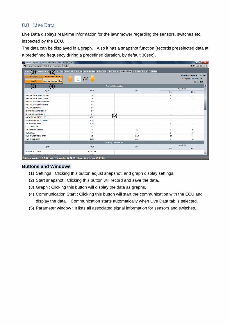
8.8 Live Data
Live Data displays real-time information for the lawnmower regarding the sensors, switches etc.
inspected by the ECU.
The data can be displayed in a graph. Also it has a snapshot function (records preselected data at
a predefined frequency during a predefined duration, by default 30sec).
Buttons and Windows
(1) Settings : Clicking this button adjust snapshot, and graph display settings.
(2) Start snapshot : Clicking this button will record and save the data.
(3) Graph : Clicking this button will display the data as graphs.
(4) Communication Start : Clicking this button will start the communication with the ECU and
display the data. Communication starts automatically when Live Data tab is selected.
(5) Parameter window : It lists all associated signal information for sensors and switches.
(2)
(3) (4)
(5)
(1)
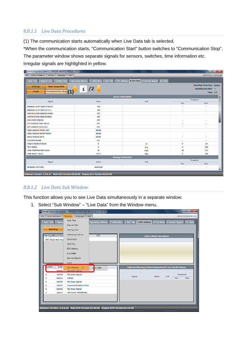
8.8.1.1 Live Data Procedures
(1) The communication starts automatically when Live Data tab is selected.
*When the communication starts, "Communication Start" button switches to "Communication Stop".
The parameter window shows separate signals for sensors, switches, time information etc.
Irregular signals are highlighted in yellow.
8.8.1.2 Live Data Sub Window
This function allows you to see Live Data simultaneously in a separate window.
1. Select “Sub Window” – “Live Data” from the Window menu.
(1)
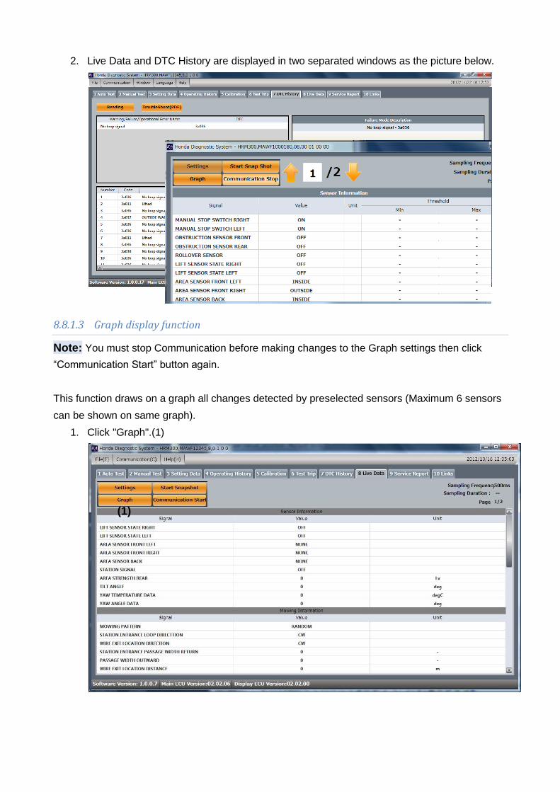
2. Live Data and DTC History are displayed in two separated windows as the picture below.
8.8.1.3 Graph display function
Note: You must stop Communication before making changes to the Graph settings then click
“Communication Start” button again.
This function draws on a graph all changes detected by preselected sensors (Maximum 6 sensors
can be shown on same graph).
1. Click "Graph".(1)
(1)

2. The graph window is displayed. Click "Settings" (2)
3. The following settings window is displayed. Set the selected signals, maximum value,
minimum value, color, weight etc. that you want for the graph.
4. You can customize axis of the graph (4)
(4-1) maximum value and minimum value for each Y1 and Y2 axis
(4-2) select sensor unit for each Y1 & Y2 axis
(4-3) X axis scale setup (in seconds)
Graph: Put in a
tick for each
parameter you
wish to display (6
sensors maximum
on same graph).
(2)
(4)
(4-2)
(4-1)
(4-3)
(4-1)
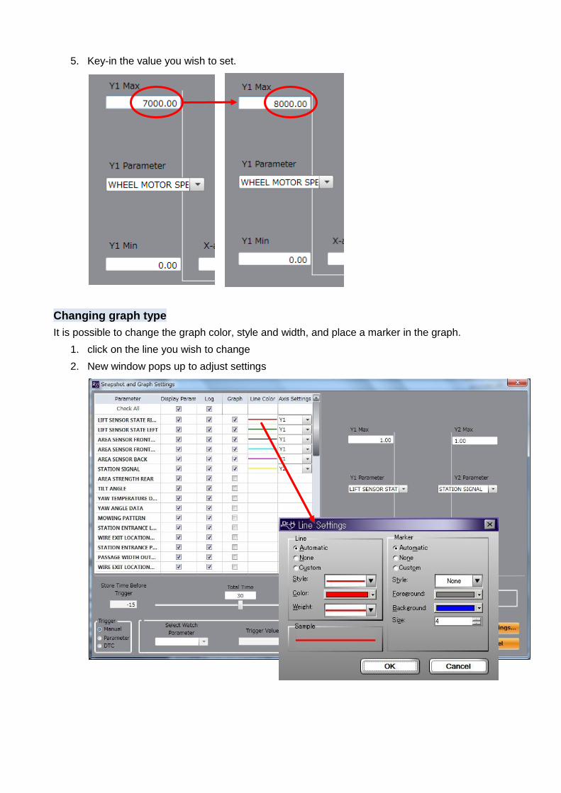
5. Key-in the value you wish to set.
Changing graph type
It is possible to change the graph color, style and width, and place a marker in the graph.
1. click on the line you wish to change
2. New window pops up to adjust settings

Line types window_Changing style
Select the line style from the dropdown menu.
Line types window_Changing weight
Select the line weight from the dropdown menu.
Line types window_Changing color
Select the line color from the checkbox.
Line types window_Setting marker
It is possible to choose whether to have markers
or not, and to set the style.

8.8.1.4 Snapshot function
Signal for starting the data recording is called the "trigger". It is possible to change the trigger method
in the settings (3) from manual trigger to DTC trigger or parameter trigger.
Manual Trigger:
Default DrH setting is 30 second recording and manual trigger.
1. Click "Communication Start" (1).
2. Click "Start Snapshot" (2).
When the "Start Snapshot" button is clicked, the button's name changes to "End Snapshot"
and data are recorded automatically in a file on your computer. This file can later be opened
via “File / Open” menu.
If the button is clicked twice the snapshot will be stopped, so make sure to wait until the
snapshot has ended.
When the snapshot is finished, the following message appears.
Click the "OK" button to end the snapshot.
(3)
(1)
(2)

Changing snapshot settings:
Click "Settings" in the upper part of the window in order to make snapshots using settings other than
the initial settings.
The following window appears.
Trigger settings (4):
*DrH default setting is Manual trigger.
Type Explanation
Manual When the user clicks "Start Snapshot", the recording starts.
Parameters When the trigger value is detected and exceeded, recording starts automatically.
DTC When a DTC appears, recording starts automatically.
Click on a trigger type box to select the trigger type.
Trigger Parameters (5):
Set the trigger type to “Parameter” and select the “Watch Parameter” from the dropdown menu.
Key-in the “Trigger Value” related to the “Watch Parameter”.
Set the trigger “Condition" box to a value above or below the standard value.
(4)
(5)
(6)

Recording time (6):
Default DrH setting is 30 seconds.
1. Enter desired value as shown below (in seconds).
2. Allocate time before and after trigger:
Using a sliding bar, the recording time can be set before and after the trigger point.
High-speed sampling function.
This function makes possible to shorten the sampling time by reducing the amount of data to be
read.
1. Uncheck “Check All” box of “Log” in the next screen.
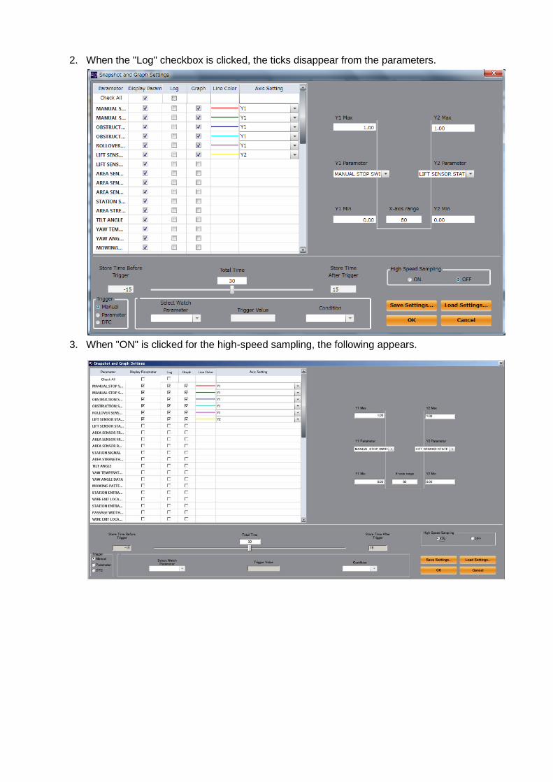
2. When the "Log" checkbox is clicked, the ticks disappear from the parameters.
3. When "ON" is clicked for the high-speed sampling, the following appears.

Save and load your settings:
It is possible to save your settings (1) and open (2) them when needed.
Saving your settings:
When "Save Settings" is clicked, the following window is displayed.
Enter the required name in the name box.
Default setting is ‘Setting 1’.
Loading saved settings:
When "Load settings" is clicked, the following message appears.
Settings you saved previously are listed in the profiles list.
Select the one you wish to open,
Press OK, you are ready to start snapshot.
(1) (2)
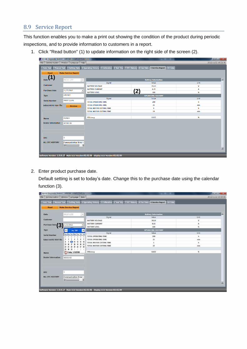
8.9 Service Report
This function enables you to make a print out showing the condition of the product during periodic
inspections, and to provide information to customers in a report.
1. Click "Read button" (1) to update information on the right side of the screen (2).
2. Enter product purchase date.
Default setting is set to today’s date. Change this to the purchase date using the calendar
function (3).
(1)
(2)
(3)
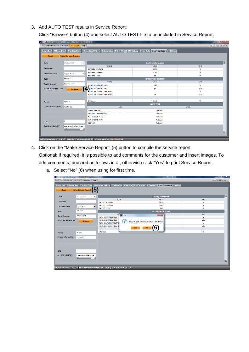
3. Add AUTO TEST results in Service Report:
Click “Browse” button (4) and select AUTO TEST file to be included in Service Report.
4. Click on the "Make Service Report" (5) button to compile the service report.
Optional: If required, it is possible to add comments for the customer and insert images. To
add comments, proceed as follows in a., otherwise click “Yes” to print Service Report.
a. Select "No" (6) when using for first time.
(4)
(5)
(6)

b. You can choose the fonts and letter sizes to be used when writing the comments.
c. Inserting image
To insert an image into the report click the "Insert Image" button.
d. Press “OK” to print Service Report.

8.10 Links
Links to PANEX and SIPS are available here.


