27
User manual for the MODBUS TCP INTERFACE DELPHYS MP & elite - DELPHYS MX & elite UPS/NTA GB/MODBUS TCP.AA 31/10/2006

User manual for the
MODBUS TCP INTERFACE
DELPHYS MP & elite - DELPHYS MX & elite
UPS/NTA GB/MODBUS TCP.AA
31/10/2006
UPS/NTA GB/MODBUSTCP.A Page 1 / 26
MODBUS TCP
FOREWORD
We thank you for the trust you have in Socomec Sicon's Uninterruptible Power Systems. This equipment is fitted with up to date technology and power semiconductors (IGBT) including a digital micro-controller. Our equipment complies with standard IEC EN 62040-2. CAUTION: “This is a product for restricted sales distribution to informed partners. Installation restrictions or additional measures may be needed to prevent disturbances”.
SOCOMEC SICON UPS reserves the right to make any changes to data without prior notice.
SAFETY REQUIREMENTS
Using conditions:
Do read carefully this manual before using. Whatever the repairs, they must be made only by authorised staffs which have been suitably trained.
UPS using conditions
Respect the safety requirements. Do read carefully the operating instructions of the UPS prior to any intervention. For an optimal operation, it is recommended to maintain the ambient temperature and humidity of the UPS environment below the values specified by the manufacturer. This equipment meets the requirements of the European directives applied to this product. As a consequence, it is labelled as follows:
ENVIRONMENT CONCERNED REGULATION
Recycling of electrical products and equipment
Provision is made in European countries to break up and recycle materials making up the system. The various components must be disposed of in accordance with the legal provisions in force in the country where the system is installed.
UPS/NTA GB/MODBUSTCP.A Page 2 / 26
MODBUS TCP
CONTENTS
FOREWORD ................................................................................................................................................................1
SAFETY REQUIREMENTS..........................................................................................................................................1
ENVIRONMENT CONCERNED REGULATION ..........................................................................................................1
1. INTRODUCTION ......................................................................................................................................................3
2. INSTALLATION OF THE MODBUS TCP PCB ........................................................................................................4
3. DEFAULT SETTING OF THE MODBUS TCP INTERFACE....................................................................................7
4. MODBUS TCP DATA MAP IN A SINGLE UNIT ......................................................................................................8
5. MODBUS TCP DATA MAP IN PARALLEL SYSTEMS..........................................................................................15
ANNEXE 1: SETTING OF THE INTERFACE USING DIGI DEVICE DICOVERY© ..................................................23
ANNEXE 2: MODBUS TCP IDA SPECIFICATION ....................................................................................................26
UPS/NTA GB/MODBUSTCP.A Page 3 / 26
MODBUS TCP
1. INTRODUCTION
General DELPHYS MX and DELPHYS MP equipment can be provided with a MODBUS TCP type interface for direct UPS connection to the Ethernet. This manual describes the features of the connection as well as the data available through the network.
Ethernet Interface The interface proposes 2 types of connection: - the « real port »mode, for which the host detects the communication as a standard serial port. - the full TCP mode as per specifications « modbus-ida ». This document does not describe the way the MODBUS TCP protocol is managed. For further details, please visit the official website www.modbus-ida.org. A summary of IDA specifications can be found at the end of the document. The MODBUS TCP protocol for DELPHYS MX and MP equipment uses Input Registers -3- with a 16 bit coding for data reading and Write single Registers -6- for UPS management. The data field is composed of words with a most significant byte (MSB) and a less significant byte (LSB) read as follows:
DATA (WORD) MSB LSB
b7 b0 b7 b0b15 b0
Data decoding
Binary data They consist of the status and alarms of the UPS. Each bit of each word corresponds to a data. When set at 1 in a word, the bit means the status or alarm is active. Analogue data (measurement and counter data) They consist of a 16-bit word. Some values are expressed in decimals bearing a sign or not (i.e. 0 to 65535 or -32767 to 32767) or in hexadecimal coding (0x0000 to 0xFFFF).
UPS/NTA GB/MODBUSTCP.A Page 4 / 26
MODBUS TCP
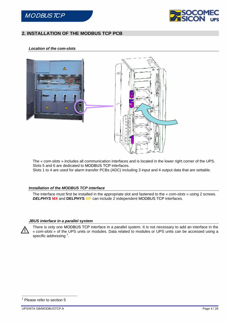
2. INSTALLATION OF THE MODBUS TCP PCB
Location of the com-slots
The « com-slots » includes all communication interfaces and is located in the lower right corner of the UPS. Slots 5 and 6 are dedicated to MMOODDBBUUSS TTCCPP interfaces. Slots 1 to 4 are used for alarm transfer PCBs (ADC) including 3 input and 4 output data that are settable.
Installation of the MODBUS TCP interface The interface must first be installed in the appropriate slot and fastened to the « com-slots » using 2 screws. DELPHYS MX and DELPHYS MP can include 2 independent MMOODDBBUUSS TTCCPP interfaces.
JBUS interface in a parallel system There is only one MMOODDBBUUSS TTCCPP interface in a parallel system. It is not necessary to add an interface in the « com-slots » of the UPS units or modules. Data related to modules or UPS units can be accessed using a specific addressing 1.
1 Please refer to section 5
UPS/NTA GB/MODBUSTCP.A Page 5 / 26
MODBUS TCP
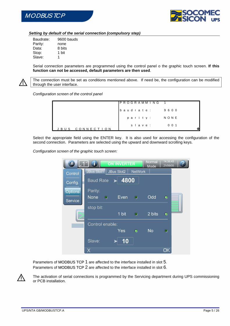
Setting by default of the serial connection (compulsory step) Baudrate: 9600 bauds Parity: none Data: 8 bits Stop: 1 bit Slave: 1
Serial connection parameters are programmed using the control panel o the graphic touch screen. If this function can not be accessed, default parameters are then used. The connection must be set as conditions mentioned above. If need be, the configuration can be modified through the user interface. Configuration screen of the control panel
P R O G R A M M I N G 1
b a u d r a t e : 9 6 0 0
p a r i t y : N O N E
s l a v e : 0 0 1J B U S C O N N E C T I O N
Select the appropriate field using the ENTER key. It is also used for accessing the configuration of the second connection. Parameters are selected using the upward and downward scrolling keys. Configuration screen of the graphic touch screen:
Parameters of MMOODDBBUUSS TTCCPP 1 are affected to the interface installed in slot 5. Parameters of MMOODDBBUUSS TTCCPP 2 are affected to the interface installed in slot 6. The activation of serial connections is programmed by the Servicing department during UPS commissioning or PCB installation.

UPS/NTA GB/MODBUSTCP.A Page 6 / 26
MODBUS TCP
Description of LEDs Yellow LED RJ45: ON: Line detected Blinking: Searching line (If any WiFi option) OFF: No EThernet line Green LED RJ45: ON: OFF: No traffic Blinking: MODBUS TCP Traffic Interface green LED TX ON: when transmitting data Interface green LED RX ON: when receiving data LED 5V iso Interface live
Features IEEE 802.3 10/100Base-T 10/100Mbps (auto sensing) mode Half-duplex & Full-duplex (auto sensing) RJ-45
UPS/NTA GB/MODBUSTCP.A Page 7 / 26
MODBUS TCP
3. DEFAULT SETTING OF THE MODBUS TCP INTERFACE
Default setting DHCP mode by default. No IP address set by default Mode MODBUS TCP Port TCP 502
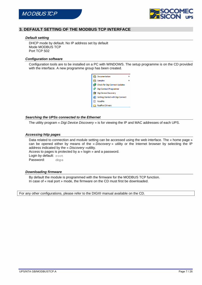
Configuration software Configuration tools are to be installed on a PC with WINDOWS. The setup programme is on the CD provided with the interface. A new programme group has been created.
Searching the UPSs connected to the Ethernet The utility program « Digi Device Discovery » is for viewing the IP and MAC addresses of each UPS.
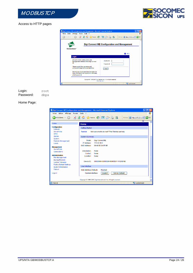
Accessing http pages Data related to connection and module setting can be accessed using the web interface. The « home page » can be opened either by means of the « Discovery » utility or the Internet browser by selecting the IP address indicated by the « Discovery »utility. Access to pages is protected by a « login » and a password. Login by default: root Password: dbps
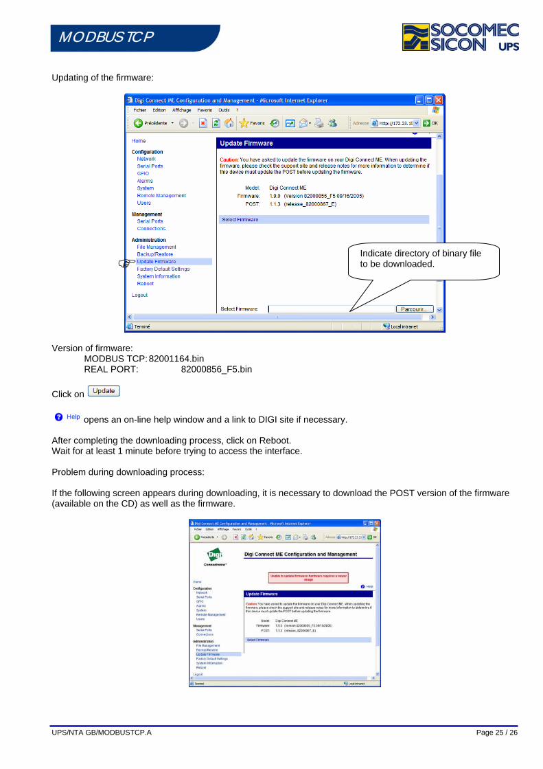
Downloading firmware By default the module is programmed with the firmware for the MODBUS TCP function. In case of « real port » mode, the firmware on the CD must first be downloaded.
For any other configurations, please refer to the DIGI® manual available on the CD.
UPS/NTA GB/MODBUSTCP.A Page 8 / 26
MODBUS TCP
4. MODBUS TCP DATA MAP IN A SINGLE UNIT
General data map
§
DATA MAP
Start register
Hexa Decimal
Length in words
JBUS Function
1 UPS Identification 0x1000 4096 12 function 3 (reading) 2 Date and time of UPS 0x1360 4960 4 function 3 (reading) 3 UPS configurations 0x10E0 4320 32 function 3 (reading) 4 Status (96 bits) 0x1020 4128 6 function 3 (reading) 5 Alarms (64 bits) 0x1040 4160 4 function 3 (reading) 6 Measurements 0x1060 4192 48 function 3 (reading) 7 Commands Permission 0x15C0 5568 2 function 3 (reading) 8 Commands 0x15B0 5552 1 6 write register
How to read data: Identification, status and alarm data maps must be read completely (start register and length in words). Measurement data map can be read word by word or by set of words, but without exceeding the length of the data map (from 0x1060 to 0x108F). Incoming data structure:
Example with 6 words 1 2 3 4 5 6 7 8 9 10 11 12
MSB 0 LSB 0 MSB 1 LSB 1 MSB 2 LSB 2 MSB 3 LSB 3 MSB 4 LSB 4 MSB 5 LSB 5 WORD 0 WORD 1 WORD 2 WORD 3 WORD 4 WORD 5
b15 b0 b15 b0 b15 b0 b15 b0 b15 b0 b15 b0 S15 S00 S31 S16 S47 S32 S63 S48 S79 S64 S95 S80 A15 A00 A31 A16 A47 A32 A63 A48
M00 M01 M02 M03 M04 M05 (Snn index of status, Ann index of alarms, Mnn index of measurements)
‘Concentrator Mode’ in a parallel system The MMOODDBBUUSS TTCCPP data map above can also be used in a parallel system. Binary data of each module or UPS unit are indeed combined to get a "virtual" single system. Logic combination ‘OR’ is used except for data S00, S05, S15, A02, A07 and A31 that are defined in a different way depending on the redundancy conditions of the parallel system
Binary data Logic combination in a redundant system
Logic combination in a non redundant system
S00 OR AND S05 AND OR S15 AND OR A02 AND OR A07 AND OR A31 AND OR
UPS/NTA GB/MODBUSTCP.A Page 9 / 26
MODBUS TCP
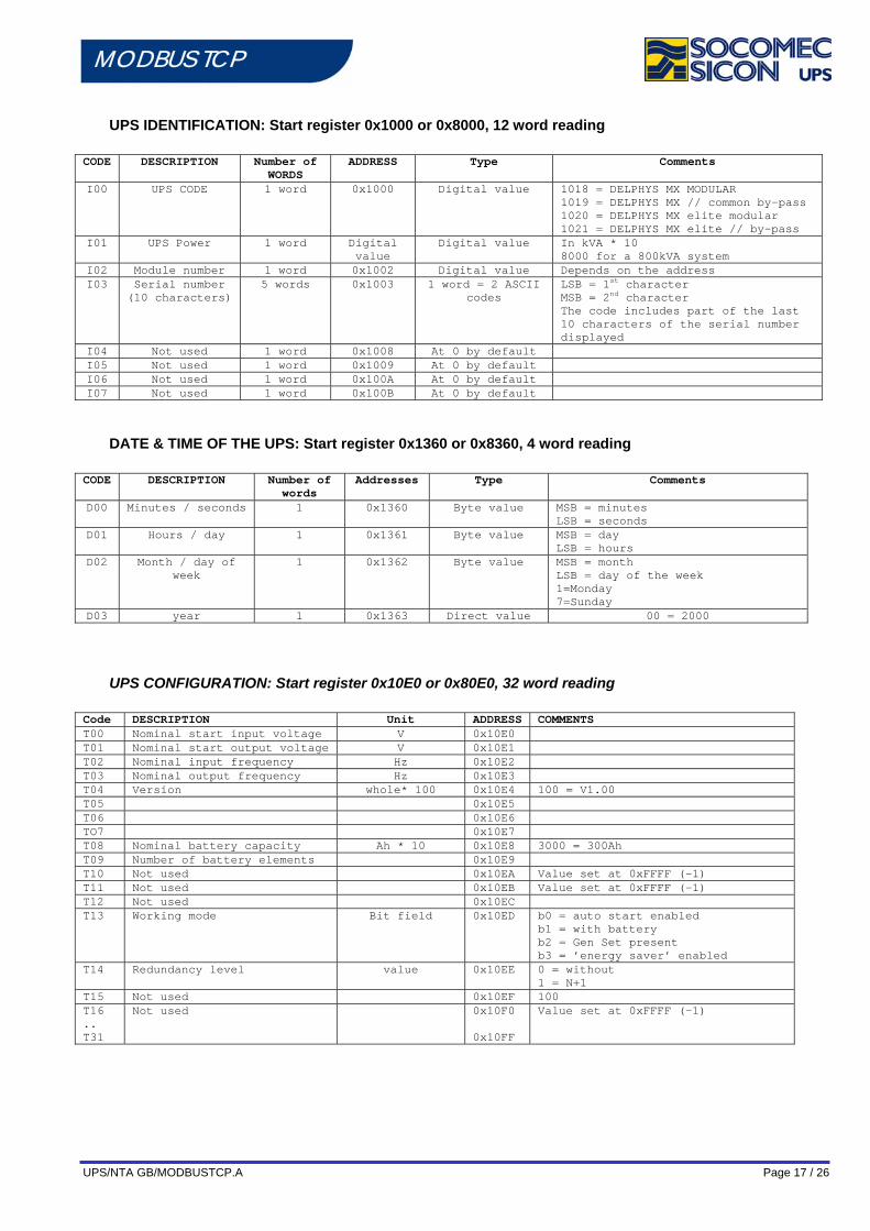
UPS IDENTIFICATION: Start register 0x1000, 12 word reading CODE DESCRIPTION Number of
words ADDRESS Data type Comments
I00 UPS CODE 1 word 0x1000 Digital value 515 = DELPHYS MX 516 = DELPHYS MX elite
I01 UPS power 1 word 0x1001 Digital value In kVA * 10 5000 for a 500kVA UPS
I02 Number of module 1 word 0x1002 Digital value 1 I03 Serial number
over 10 characters
5 words 0x1003 1 word = 2 ASCII codes
LSB = 1st character MSB = 2nd character Code of origin:CCCCCCAaYYYXXXXXXNNn Code read:aXXXXXNNn
I04 Not used 1 word 0x1008 0 by default I05 Not used 1 word 0x1009 0 by default I06 Not used 1 word 0x100A 0 by default I07 Not used 1 word 0x100B 0 by default
DATE & TIME OF THE UPS: Start register 0x1360, 4 word reading CODE DESCRIPTION Number of
words ADDRESS Type Comments
D00 Minutes / seconds 1 0x1360 Byte value MSB = minutes LSB = seconds
D01 Hours / day 1 0x1361 Byte value MSB = day LSB = hours
D02 Month / day of the week
1 0x1362 Byte value MSB = month LSB = day of the week 1=Monday 7=Sunday
D03 Year 1 0x1363 Direct value 00 = 2000
UPS CONFIGURATION: Start register 0x10E0, 32 word reading Code DESCRIPTION Unit ADDRESS COMMENTS T00 Nominal start input voltage V 0x10E0 T01 Nominal start output voltage V 0x10E1 T02 Nominal input frequency Hz 0x10E2 T03 Nominal output frequency Hz 0x10E3 T04 Version whole* 100 0x10E4 100 = V1.00 T05 0x10E5 T06 0x10E6 TO7 0x10E7 T08 Nominal battery capacity Ah * 10 0x10E8 3000 = 300Ah T09 Number of battery elements 0x10E9 T10 Reserved 0x10EA Value set at 0xFFFF (-1) T11 Reserved 0x10EB Value set at 0xFFFF (-1) T12 Reserved 0x10EC T13 Working mode Bit field
0x10ED b0 = not used
b1 = with battery b2 = Gen Set present b3 = ’energy saver’ enabled
T14 Redundancy level value 0x10EE 0 = without 1 = N+1
T15 Reserved 0x10EF 100 T16 .. T31
Reserved
0x10F0 0x10FF
Value set at 0xFFFF (-1)
UPS/NTA GB/MODBUSTCP.A Page 10 / 26
MODBUS TCP
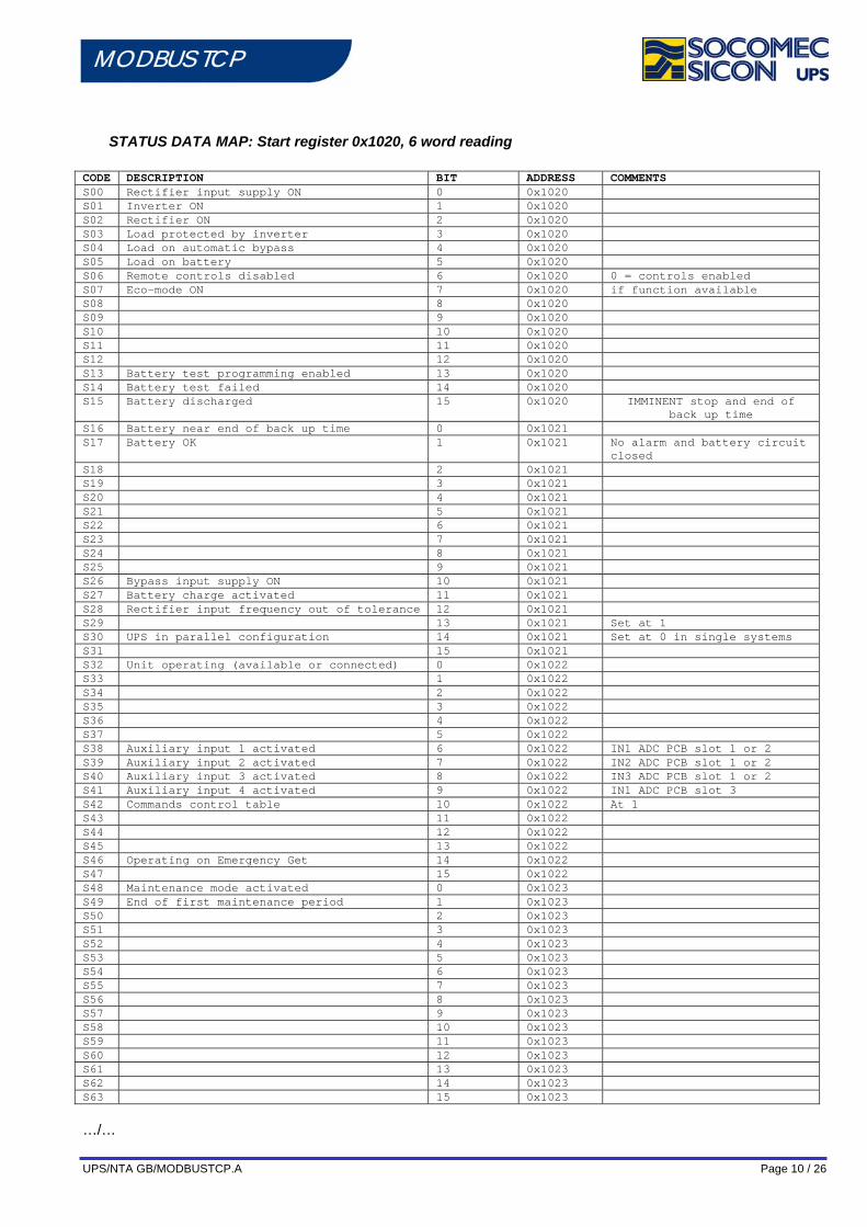
STATUS DATA MAP: Start register 0x1020, 6 word reading CODE DESCRIPTION BIT ADDRESS COMMENTS S00 Rectifier input supply ON 0 0x1020 S01 Inverter ON 1 0x1020 S02 Rectifier ON 2 0x1020 S03 Load protected by inverter 3 0x1020 S04 Load on automatic bypass 4 0x1020 S05 Load on battery 5 0x1020 S06 Remote controls disabled 6 0x1020 0 = controls enabled S07 Eco-mode ON 7 0x1020 if function available S08 8 0x1020 S09 9 0x1020 S10 10 0x1020 S11 11 0x1020 S12 12 0x1020 S13 Battery test programming enabled 13 0x1020 S14 Battery test failed 14 0x1020 S15 Battery discharged 15 0x1020 IMMINENT stop and end of
back up time S16 Battery near end of back up time 0 0x1021 S17 Battery OK 1 0x1021 No alarm and battery circuit
closed S18 2 0x1021 S19 3 0x1021 S20 4 0x1021 S21 5 0x1021 S22 6 0x1021 S23 7 0x1021 S24 8 0x1021 S25 9 0x1021 S26 Bypass input supply ON 10 0x1021 S27 Battery charge activated 11 0x1021 S28 Rectifier input frequency out of tolerance 12 0x1021 S29 13 0x1021 Set at 1 S30 UPS in parallel configuration 14 0x1021 Set at 0 in single systems S31 15 0x1021 S32 Unit operating (available or connected) 0 0x1022 S33 1 0x1022 S34 2 0x1022 S35 3 0x1022 S36 4 0x1022 S37 5 0x1022 S38 Auxiliary input 1 activated 6 0x1022 IN1 ADC PCB slot 1 or 2 S39 Auxiliary input 2 activated 7 0x1022 IN2 ADC PCB slot 1 or 2 S40 Auxiliary input 3 activated 8 0x1022 IN3 ADC PCB slot 1 or 2 S41 Auxiliary input 4 activated 9 0x1022 IN1 ADC PCB slot 3 S42 Commands control table 10 0x1022 At 1 S43 11 0x1022 S44 12 0x1022 S45 13 0x1022 S46 Operating on Emergency Get 14 0x1022 S47 15 0x1022 S48 Maintenance mode activated 0 0x1023 S49 End of first maintenance period 1 0x1023 S50 2 0x1023 S51 3 0x1023 S52 4 0x1023 S53 5 0x1023 S54 6 0x1023 S55 7 0x1023 S56 8 0x1023 S57 9 0x1023 S58 10 0x1023 S59 11 0x1023 S60 12 0x1023 S61 13 0x1023 S62 14 0x1023 S63 15 0x1023
…/…
UPS/NTA GB/MODBUSTCP.A Page 11 / 26
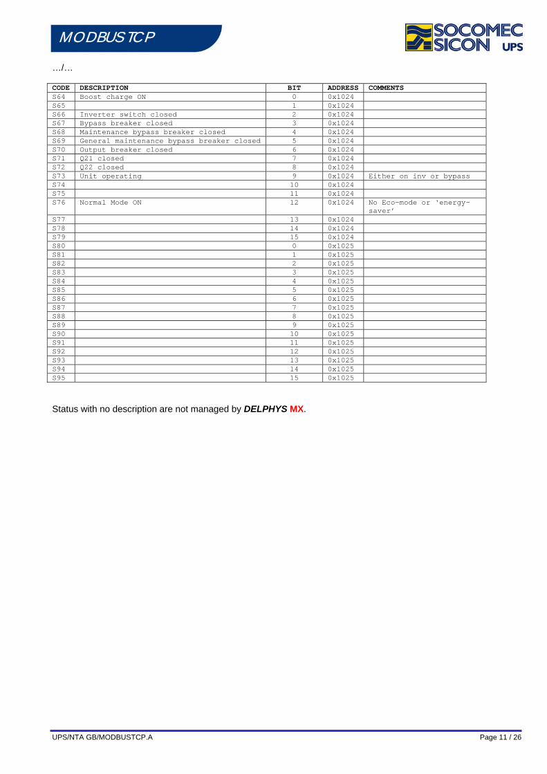
MODBUS TCP …/… CODE DESCRIPTION BIT ADDRESS COMMENTS S64 Boost charge ON 0 0x1024 S65 1 0x1024 S66 Inverter switch closed 2 0x1024 S67 Bypass breaker closed 3 0x1024 S68 Maintenance bypass breaker closed 4 0x1024 S69 General maintenance bypass breaker closed 5 0x1024 S70 Output breaker closed 6 0x1024 S71 Q21 closed 7 0x1024 S72 Q22 closed 8 0x1024 S73 Unit operating 9 0x1024 Either on inv or bypass S74 10 0x1024 S75 11 0x1024 S76 Normal Mode ON 12 0x1024 No Eco-mode or ‘energy-
saver’ S77 13 0x1024 S78 14 0x1024 S79 15 0x1024 S80 0 0x1025 S81 1 0x1025 S82 2 0x1025 S83 3 0x1025 S84 4 0x1025 S85 5 0x1025 S86 6 0x1025 S87 7 0x1025 S88 8 0x1025 S89 9 0x1025 S90 10 0x1025 S91 11 0x1025 S92 12 0x1025 S93 13 0x1025 S94 14 0x1025 S95 15 0x1025
Status with no description are not managed by DELPHYS MX.
UPS/NTA GB/MODBUSTCP.A Page 12 / 26
MODBUS TCP
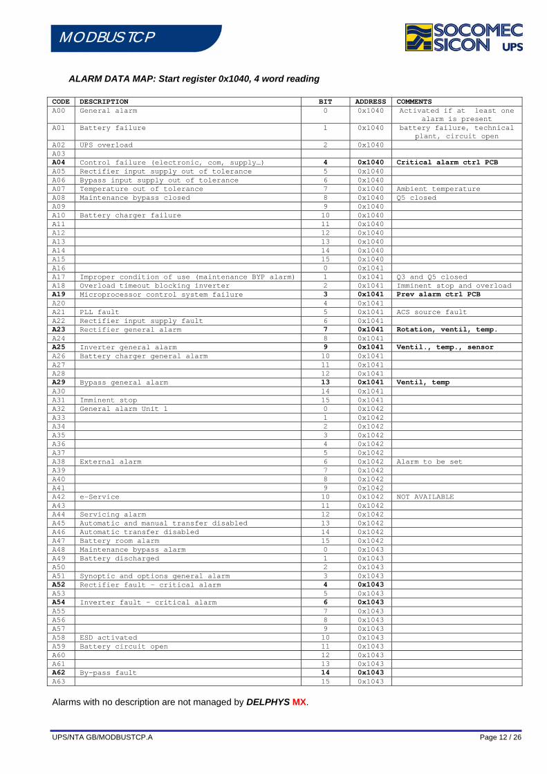
ALARM DATA MAP: Start register 0x1040, 4 word reading CODE DESCRIPTION BIT ADDRESS COMMENTS A00 General alarm 0 0x1040 Activated if at least one
alarm is present A01 Battery failure 1 0x1040 battery failure, technical
plant, circuit open A02 UPS overload 2 0x1040 A03 A04 Control failure (electronic, com, supply…) 4 0x1040 Critical alarm ctrl PCB A05 Rectifier input supply out of tolerance 5 0x1040 A06 Bypass input supply out of tolerance 6 0x1040 A07 Temperature out of tolerance 7 0x1040 Ambient temperature A08 Maintenance bypass closed 8 0x1040 Q5 closed A09 9 0x1040 A10 Battery charger failure 10 0x1040 A11 11 0x1040 A12 12 0x1040 A13 13 0x1040 A14 14 0x1040 A15 15 0x1040 A16 0 0x1041 A17 Improper condition of use (maintenance BYP alarm) 1 0x1041 Q3 and Q5 closed A18 Overload timeout blocking inverter 2 0x1041 Imminent stop and overload A19 Microprocessor control system failure 3 0x1041 Prev alarm ctrl PCB A20 4 0x1041 A21 PLL fault 5 0x1041 ACS source fault A22 Rectifier input supply fault 6 0x1041 A23 Rectifier general alarm 7 0x1041 Rotation, ventil, temp. A24 8 0x1041 A25 Inverter general alarm 9 0x1041 Ventil., temp., sensor A26 Battery charger general alarm 10 0x1041 A27 11 0x1041 A28 12 0x1041 A29 Bypass general alarm 13 0x1041 Ventil, temp A30 14 0x1041 A31 Imminent stop 15 0x1041 A32 General alarm Unit 1 0 0x1042 A33 1 0x1042 A34 2 0x1042 A35 3 0x1042 A36 4 0x1042 A37 5 0x1042 A38 External alarm 6 0x1042 Alarm to be set A39 7 0x1042 A40 8 0x1042 A41 9 0x1042 A42 e-Service 10 0x1042 NOT AVAILABLE A43 11 0x1042 A44 Servicing alarm 12 0x1042 A45 Automatic and manual transfer disabled 13 0x1042 A46 Automatic transfer disabled 14 0x1042 A47 Battery room alarm 15 0x1042 A48 Maintenance bypass alarm 0 0x1043 A49 Battery discharged 1 0x1043 A50 2 0x1043 A51 Synoptic and options general alarm 3 0x1043 A52 Rectifier fault – critical alarm 4 0x1043 A53 5 0x1043 A54 Inverter fault – critical alarm 6 0x1043 A55 7 0x1043 A56 8 0x1043 A57 9 0x1043 A58 ESD activated 10 0x1043 A59 Battery circuit open 11 0x1043 A60 12 0x1043 A61 13 0x1043 A62 By-pass fault 14 0x1043 A63 15 0x1043
Alarms with no description are not managed by DELPHYS MX.
UPS/NTA GB/MODBUSTCP.A Page 13 / 26
MODBUS TCP
MEASUREMENT DATA MAP: Start register 0x1060, 48 word reading
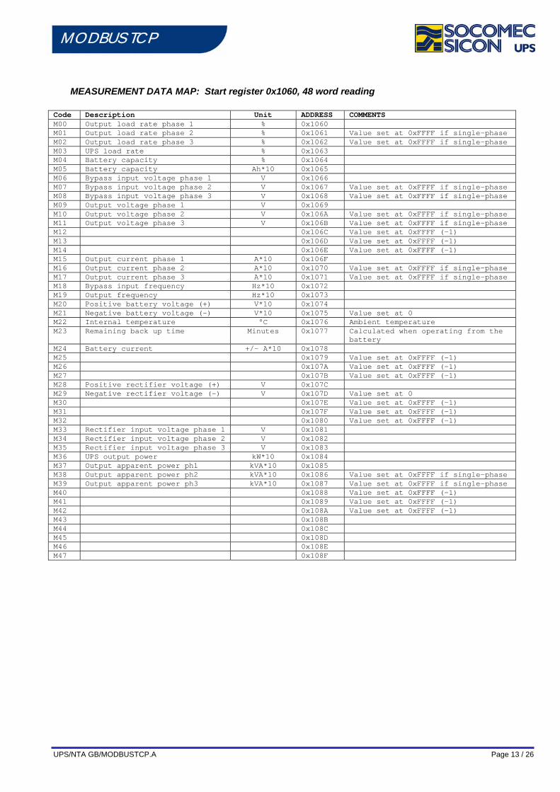
Code Description Unit ADDRESS COMMENTS M00 Output load rate phase 1 % 0x1060 M01 Output load rate phase 2 % 0x1061 Value set at 0xFFFF if single-phase M02 Output load rate phase 3 % 0x1062 Value set at 0xFFFF if single-phase M03 UPS load rate % 0x1063 M04 Battery capacity % 0x1064 M05 Battery capacity Ah*10 0x1065 M06 Bypass input voltage phase 1 V 0x1066 M07 Bypass input voltage phase 2 V 0x1067 Value set at 0xFFFF if single-phase M08 Bypass input voltage phase 3 V 0x1068 Value set at 0xFFFF if single-phase M09 Output voltage phase 1 V 0x1069 M10 Output voltage phase 2 V 0x106A Value set at 0xFFFF if single-phase M11 Output voltage phase 3 V 0x106B Value set at 0xFFFF if single-phase M12 0x106C Value set at 0xFFFF (-1) M13 0x106D Value set at 0xFFFF (-1) M14 0x106E Value set at 0xFFFF (-1) M15 Output current phase 1 A*10 0x106F M16 Output current phase 2 A*10 0x1070 Value set at 0xFFFF if single-phase M17 Output current phase 3 A*10 0x1071 Value set at 0xFFFF if single-phase M18 Bypass input frequency Hz*10 0x1072 M19 Output frequency Hz*10 0x1073 M20 Positive battery voltage (+) V*10 0x1074 M21 Negative battery voltage (-) V*10 0x1075 Value set at 0 M22 Internal temperature °C 0x1076 Ambient temperature M23 Remaining back up time Minutes 0x1077 Calculated when operating from the
battery M24 Battery current +/- A*10 0x1078 M25 0x1079 Value set at 0xFFFF (-1) M26 0x107A Value set at 0xFFFF (-1) M27 0x107B Value set at 0xFFFF (-1) M28 Positive rectifier voltage (+) V 0x107C M29 Negative rectifier voltage (-) V 0x107D Value set at 0 M30 0x107E Value set at 0xFFFF (-1) M31 0x107F Value set at 0xFFFF (-1) M32 0x1080 Value set at 0xFFFF (-1) M33 Rectifier input voltage phase 1 V 0x1081 M34 Rectifier input voltage phase 2 V 0x1082 M35 Rectifier input voltage phase 3 V 0x1083 M36 UPS output power kW*10 0x1084 M37 Output apparent power ph1 kVA*10 0x1085 M38 Output apparent power ph2 kVA*10 0x1086 Value set at 0xFFFF if single-phase M39 Output apparent power ph3 kVA*10 0x1087 Value set at 0xFFFF if single-phase M40 0x1088 Value set at 0xFFFF (-1) M41 0x1089 Value set at 0xFFFF (-1) M42 0x108A Value set at 0xFFFF (-1) M43 0x108B M44 0x108C M45 0x108D M46 0x108E M47 0x108F
UPS/NTA GB/MODBUSTCP.A Page 14 / 26
MODBUS TCP
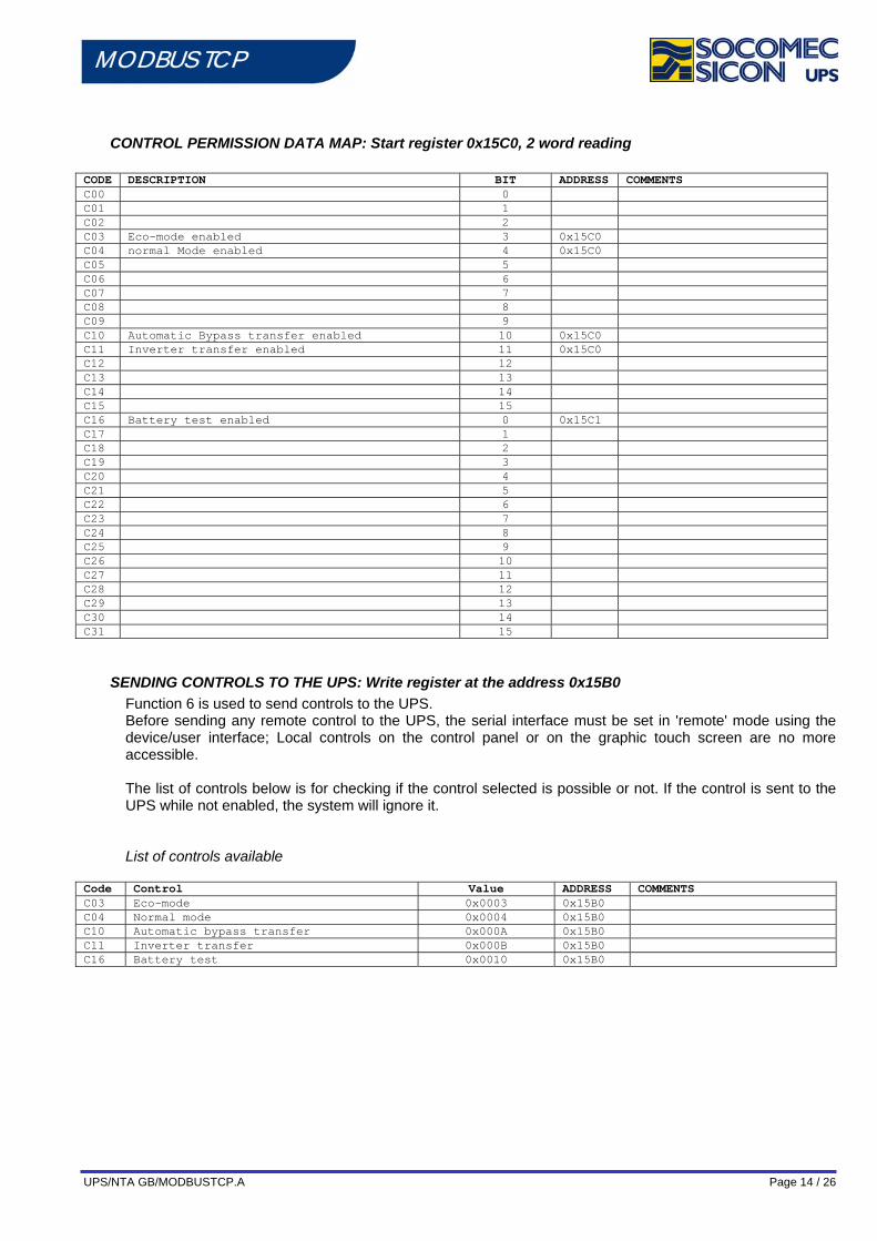
CONTROL PERMISSION DATA MAP: Start register 0x15C0, 2 word reading
CODE DESCRIPTION BIT ADDRESS COMMENTS C00 0 C01 1 C02 2 C03 Eco-mode enabled 3 0x15C0 C04 normal Mode enabled 4 0x15C0 C05 5 C06 6 C07 7 C08 8 C09 9 C10 Automatic Bypass transfer enabled 10 0x15C0 C11 Inverter transfer enabled 11 0x15C0 C12 12 C13 13 C14 14 C15 15 C16 Battery test enabled 0 0x15C1 C17 1 C18 2 C19 3 C20 4 C21 5 C22 6 C23 7 C24 8 C25 9 C26 10 C27 11 C28 12 C29 13 C30 14 C31 15
SENDING CONTROLS TO THE UPS: Write register at the address 0x15B0 Function 6 is used to send controls to the UPS. Before sending any remote control to the UPS, the serial interface must be set in 'remote' mode using the device/user interface; Local controls on the control panel or on the graphic touch screen are no more accessible. The list of controls below is for checking if the control selected is possible or not. If the control is sent to the UPS while not enabled, the system will ignore it. List of controls available
Code Control Value ADDRESS COMMENTS C03 Eco-mode 0x0003 0x15B0 C04 Normal mode 0x0004 0x15B0 C10 Automatic bypass transfer 0x000A 0x15B0 C11 Inverter transfer 0x000B 0x15B0 C16 Battery test 0x0010 0x15B0
UPS/NTA GB/MODBUSTCP.A Page 15 / 26
MODBUS TCP
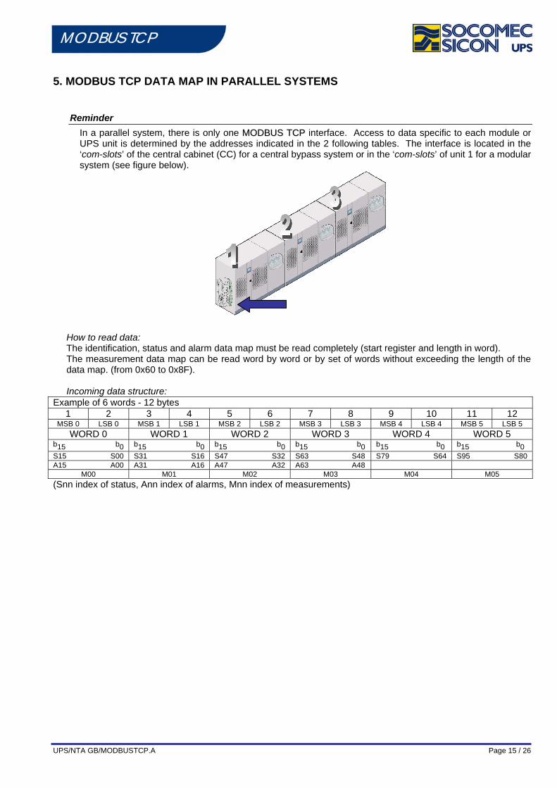
5. MODBUS TCP DATA MAP IN PARALLEL SYSTEMS
Reminder In a parallel system, there is only one MMOODDBBUUSS TTCCPP interface. Access to data specific to each module or UPS unit is determined by the addresses indicated in the 2 following tables. The interface is located in the ‘com-slots’ of the central cabinet (CC) for a central bypass system or in the ‘com-slots’ of unit 1 for a modular system (see figure below).
How to read data: The identification, status and alarm data map must be read completely (start register and length in word). The measurement data map can be read word by word or by set of words without exceeding the length of the data map. (from 0x60 to 0x8F).
Incoming data structure:
Example of 6 words - 12 bytes 1 2 3 4 5 6 7 8 9 10 11 12
MSB 0 LSB 0 MSB 1 LSB 1 MSB 2 LSB 2 MSB 3 LSB 3 MSB 4 LSB 4 MSB 5 LSB 5 WORD 0 WORD 1 WORD 2 WORD 3 WORD 4 WORD 5
b15 b0 b15 b0 b15 b0 b15 b0 b15 b0 b15 b0 S15 S00 S31 S16 S47 S32 S63 S48 S79 S64 S95 S80 A15 A00 A31 A16 A47 A32 A63 A48
M00 M01 M02 M03 M04 M05 (Snn index of status, Ann index of alarms, Mnn index of measurements)
UPS/NTA GB/MODBUSTCP.A Page 16 / 26
MODBUS TCP
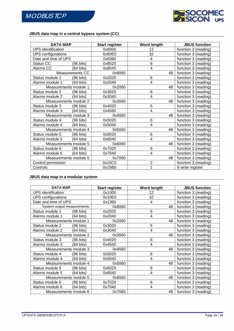
JBUS data map in a central bypass system (CC)
DATA MAP Start register Word length JBUS function UPS identification 0x8000 12 function 3 (reading) UPS configurations 0x80E0 32 function 3 (reading) Date and time of UPS 0x8360 4 function 3 (reading) Status CC (96 bits) 0x8020 6 function 3 (reading) Alarms CC (64 bits) 0x8040 4 function 3 (reading)
Measurements CC 0x8060 48 function 3 (reading) Status module 1 (96 bits) 0x2020 6 function 3 (reading) Alarms module 1 (64 bits) 0x2040 4 function 3 (reading)
Measurements module 1 0x2060 48 function 3 (reading) Status module 2 (96 bits) 0x3020 6 function 3 (reading) Alarms module 2 (64 bits) 0x3040 4 function 3 (reading)
Measurements module 2 0x3060 48 function 3 (reading) Status module 3 (96 bits) 0x4020 6 function 3 (reading) Alarms module 3 (64 bits) 0x4040 4 function 3 (reading)
Measurements module 3 0x4060 48 function 3 (reading) Status module 4 (96 bits) 0x5020 6 function 3 (reading) Alarms module 4 (64 bits) 0x5040 4 function 3 (reading)
Measurements module 4 0x5060 48 function 3 (reading) Status module 5 (96 bits) 0x6020 6 function 3 (reading) Alarms module 5 (64 bits) 0x6040 4 function 3 (reading)
Measurements module 5 0x6060 48 function 3 (reading) Status module 6 (96 bits) 0x7020 6 function 3 (reading) Alarms module 6 (64 bits) 0x7040 4 function 3 (reading)
Measurements module 6 0x7060 48 function 3 (reading) Control permission 0x15C0 2 function 3 (reading) Controls 0x15B0 1 6 write register
JBUS data map in a modular system
DATA MAP Start register Word length JBUS function UPS identification 0x1000 12 function 3 (reading) UPS configurations 0x10E0 32 function 3 (reading) Date and time of UPS 0x1360 4 function 3 (reading)
System output measurements 0x8060 48 function 3 (reading) Status module 1 (96 bits) 0x2020 6 function 3 (reading) Alarms module 1 (64 bits) 0x2040 4 function 3 (reading)
Measurements module 1 0x2060 48 function 3 (reading) Status module 2 (96 bits) 0x3020 6 function 3 (reading) Alarms module 2 (64 bits) 0x3040 4 function 3 (reading)
Measurements module 2 0x3060 48 function 3 (reading) Status module 3 (96 bits) 0x4020 6 function 3 (reading) Alarms module 3 (64 bits) 0x4040 4 function 3 (reading)
Measurements module 3 0x4060 48 function 3 (reading) Status module 4 (96 bits) 0x5020 6 function 3 (reading) Alarms module 4 (64 bits) 0x5040 4 function 3 (reading)
Measurements module 4 0x5060 48 function 3 (reading) Status module 5 (96 bits) 0x6020 6 function 3 (reading) Alarms module 5 (64 bits) 0x6040 4 function 3 (reading)
Measurements module 5 0x6060 48 function 3 (reading) Status module 6 (96 bits) 0x7020 6 function 3 (reading) Alarms module 6 (64 bits) 0x7040 4 function 3 (reading)
Measurements module 6 0x7060 48 function 3 (reading)
UPS/NTA GB/MODBUSTCP.A Page 17 / 26
MODBUS TCP
UPS IDENTIFICATION: Start register 0x1000 or 0x8000, 12 word reading CODE DESCRIPTION Number of
WORDS ADDRESS Type Comments
I00 UPS CODE 1 word 0x1000 Digital value 1018 = DELPHYS MX MODULAR 1019 = DELPHYS MX // common by-pass 1020 = DELPHYS MX elite modular 1021 = DELPHYS MX elite // by-pass
I01 UPS Power 1 word Digital value
Digital value In kVA * 10 8000 for a 800kVA system
I02 Module number 1 word 0x1002 Digital value Depends on the address I03 Serial number
(10 characters) 5 words 0x1003 1 word = 2 ASCII
codes LSB = 1st character MSB = 2nd character The code includes part of the last 10 characters of the serial number displayed
I04 Not used 1 word 0x1008 At 0 by default I05 Not used 1 word 0x1009 At 0 by default I06 Not used 1 word 0x100A At 0 by default I07 Not used 1 word 0x100B At 0 by default
DATE & TIME OF THE UPS: Start register 0x1360 or 0x8360, 4 word reading CODE DESCRIPTION Number of
words Addresses Type Comments
D00 Minutes / seconds 1 0x1360 Byte value MSB = minutes LSB = seconds
D01 Hours / day 1 0x1361 Byte value MSB = day LSB = hours
D02 Month / day of week
1 0x1362 Byte value MSB = month LSB = day of the week 1=Monday 7=Sunday
D03 year 1 0x1363 Direct value 00 = 2000
UPS CONFIGURATION: Start register 0x10E0 or 0x80E0, 32 word reading Code DESCRIPTION Unit ADDRESS COMMENTS T00 Nominal start input voltage V 0x10E0 T01 Nominal start output voltage V 0x10E1 T02 Nominal input frequency Hz 0x10E2 T03 Nominal output frequency Hz 0x10E3 T04 Version whole* 100 0x10E4 100 = V1.00 T05 0x10E5 T06 0x10E6 TO7 0x10E7 T08 Nominal battery capacity Ah * 10 0x10E8 3000 = 300Ah T09 Number of battery elements 0x10E9 T10 Not used 0x10EA Value set at 0xFFFF (-1) T11 Not used 0x10EB Value set at 0xFFFF (-1) T12 Not used 0x10EC T13 Working mode Bit field
0x10ED b0 = auto start enabled
b1 = with battery b2 = Gen Set present b3 = ’energy saver’ enabled
T14 Redundancy level value 0x10EE 0 = without 1 = N+1
T15 Not used 0x10EF 100 T16 .. T31
Not used 0x10F0 0x10FF
Value set at 0xFFFF (-1)
UPS/NTA GB/MODBUSTCP.A Page 18 / 26
MODBUS TCP
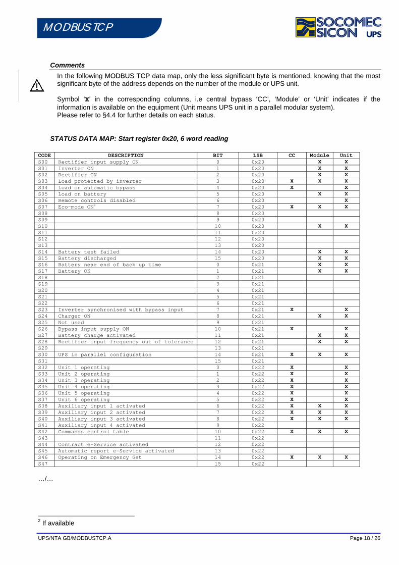
Comments In the following MMOODDBBUUSS TTCCPP data map, only the less significant byte is mentioned, knowing that the most significant byte of the address depends on the number of the module or UPS unit.
Symbol ‘X’ in the corresponding columns, i.e central bypass ‘CC’, ‘Module’ or ‘Unit’ indicates if the information is available on the equipment (Unit means UPS unit in a parallel modular system). Please refer to §4.4 for further details on each status.
STATUS DATA MAP: Start register 0x20, 6 word reading CODE DESCRIPTION BIT LSB CC Module Unit S00 Rectifier input supply ON 0 0x20 X X S01 Inverter ON 1 0x20 X X S02 Rectifier ON 2 0x20 X X S03 Load protected by inverter 3 0x20 X X X S04 Load on automatic bypass 4 0x20 X X S05 Load on battery 5 0x20 X X S06 Remote controls disabled 6 0x20 X S07 Eco-mode ON2 7 0x20 X X X S08 8 0x20 S09 9 0x20 S10 10 0x20 X X S11 11 0x20 S12 12 0x20 S13 13 0x20 S14 Battery test failed 14 0x20 X X S15 Battery discharged 15 0x20 X X S16 Battery near end of back up time 0 0x21 X X S17 Battery OK 1 0x21 X X S18 2 0x21 S19 3 0x21 S20 4 0x21 S21 5 0x21 S22 6 0x21 S23 Inverter synchronised with bypass input 7 0x21 X X S24 Charger ON 8 0x21 X X S25 Not used 9 0x21 S26 Bypass input supply ON 10 0x21 X X S27 Battery charge activated 11 0x21 X X S28 Rectifier input frequency out of tolerance 12 0x21 X X S29 13 0x21 S30 UPS in parallel configuration 14 0x21 X X X S31 15 0x21 S32 Unit 1 operating 0 0x22 X X S33 Unit 2 operating 1 0x22 X X S34 Unit 3 operating 2 0x22 X X S35 Unit 4 operating 3 0x22 X X S36 Unit 5 operating 4 0x22 X X S37 Unit 6 operating 5 0x22 X X S38 Auxiliary input 1 activated 6 0x22 X X X S39 Auxiliary input 2 activated 7 0x22 X X X S40 Auxiliary input 3 activated 8 0x22 X X X S41 Auxiliary input 4 activated 9 0x22 S42 Commands control table 10 0x22 X X X S43 11 0x22 S44 Contract e-Service activated 12 0x22 S45 Automatic report e-Service activated 13 0x22 S46 Operating on Emergency Get 14 0x22 X X X S47 15 0x22
…/…
2 If available
UPS/NTA GB/MODBUSTCP.A Page 19 / 26
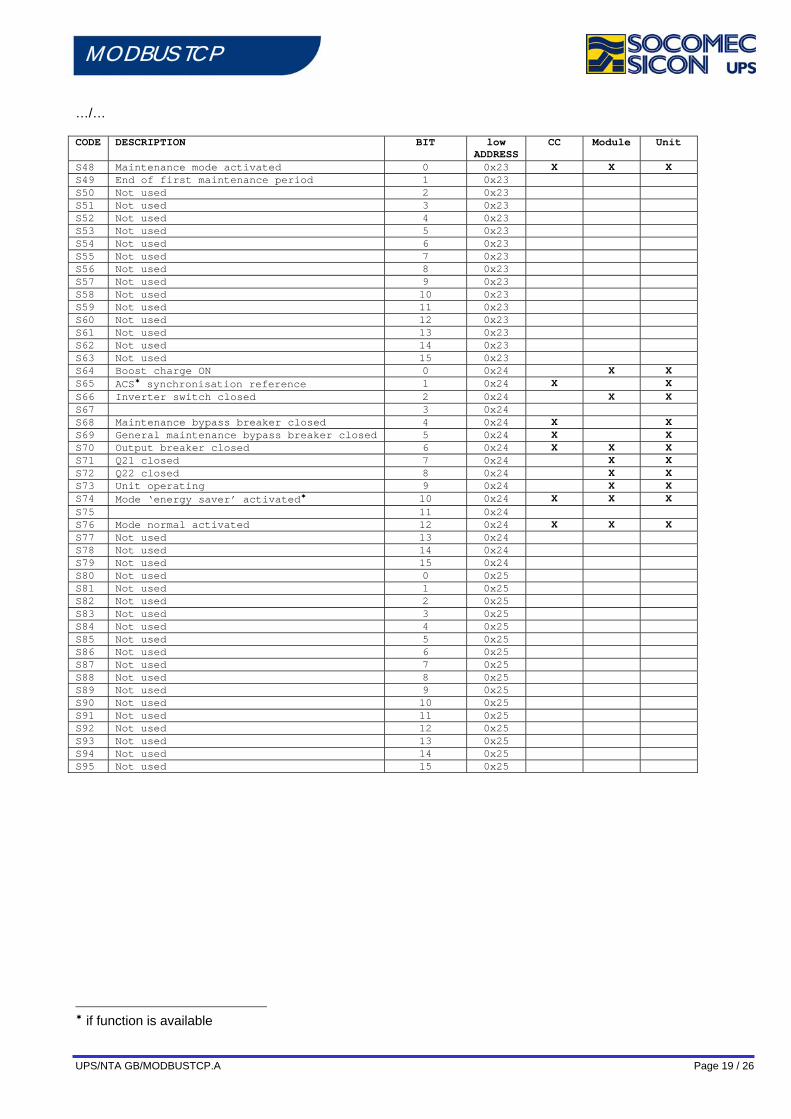
MODBUS TCP …/… CODE DESCRIPTION BIT low
ADDRESS CC Module Unit
S48 Maintenance mode activated 0 0x23 X X X S49 End of first maintenance period 1 0x23 S50 Not used 2 0x23 S51 Not used 3 0x23 S52 Not used 4 0x23 S53 Not used 5 0x23 S54 Not used 6 0x23 S55 Not used 7 0x23 S56 Not used 8 0x23 S57 Not used 9 0x23 S58 Not used 10 0x23 S59 Not used 11 0x23 S60 Not used 12 0x23 S61 Not used 13 0x23 S62 Not used 14 0x23 S63 Not used 15 0x23 S64 Boost charge ON 0 0x24 X X S65 ACS synchronisation reference 1 0x24 X X S66 Inverter switch closed 2 0x24 X X S67 3 0x24 S68 Maintenance bypass breaker closed 4 0x24 X X S69 General maintenance bypass breaker closed 5 0x24 X X S70 Output breaker closed 6 0x24 X X X S71 Q21 closed 7 0x24 X X S72 Q22 closed 8 0x24 X X S73 Unit operating 9 0x24 X X S74 Mode ‘energy saver’ activated 10 0x24 X X X S75 11 0x24 S76 Mode normal activated 12 0x24 X X X S77 Not used 13 0x24 S78 Not used 14 0x24 S79 Not used 15 0x24 S80 Not used 0 0x25 S81 Not used 1 0x25 S82 Not used 2 0x25 S83 Not used 3 0x25 S84 Not used 4 0x25 S85 Not used 5 0x25 S86 Not used 6 0x25 S87 Not used 7 0x25 S88 Not used 8 0x25 S89 Not used 9 0x25 S90 Not used 10 0x25 S91 Not used 11 0x25 S92 Not used 12 0x25 S93 Not used 13 0x25 S94 Not used 14 0x25 S95 Not used 15 0x25
if function is available

UPS/NTA GB/MODBUSTCP.A Page 20 / 26
MODBUS TCP
ALARMS: Start register 0x40, 4 word reading CODE DESCRIPTION BIT LSB CC Module Unit A00 General alarm 0 0x40 X X X A01 Battery failure 1 0x40 X X A02 UPS overload 2 0x40 X X X A03 A04 Control failure (electronic, com, supply…) 4 0x40 X X X A05 Rectifier input supply out of tolerance 5 0x40 X X X A06 Bypass input supply out of tolerance 6 0x40 X X A07 Temperature out of tolerance 7 0x40 X X X A08 Maintenance bypass closed 8 0x40 X X A09 A10 A11 A12 A13 A14 A15 A16 A17 Improper condition of use (maintenance BYP alarm) 1 0x41 X X A18 Overload timeout blocking inverter 2 0x41 X X A19 Microprocessor control system failure – preventive
alarm 3 0x41 X X X
A20 A21 PLL fault 5 0x41 X X A22 Rectifier input supply fault 6 0x41 X X A23 Rectifier general alarm – preventive alarm 7 0x41 X X A24 A25 Inverter general alarm – preventive alarm 9 0x41 X X A26 Battery charger general alarm 10 0x41 X X A27 X X A28 A29 Bypass general alarm – preventive alarm 13 0x41 X X X A30 A31 Imminent stop 15 0x41 X X X A32 General alarm Unit 1 0 0x42 X X A33 General alarm Unit 2 1 0x42 X X A34 General alarm Unit 3 2 0x42 X X A35 General alarm Unit 4 3 0x42 X X A36 General alarm Unit 5 4 0x42 X X A37 General alarm Unit 6 5 0x42 X X A38 External alarm 6 0x42 X X X A39
A40
A41
A42 General alarm E-Service 10 0x42 A43 Loss of redundancy * 11 0x42 X X A44 Servicing alarm 12 0x42 A45 Automatic and manual transfer disabled 13 0x42 X X A45 Automatic transfer disabled 14 0x42 X X A47 Battery room alarm 15 0x42 X X A48 Maintenance bypass alarm 0 0x43 X X A49 Battery discharged 1 0x43 X X A50 Insufficient resources 2 0x43 X X A51 Synoptic and options general alarm 3 0x43 A52 Rectifier fault – critical alarm 4 0x43 X X A53 A54 Inverter fault – critical alarm 6 0x43 X X A55 A56 A57 A58 ESD activated 10 0x43 X X X A59 Battery circuit open 11 0x43 X X A62 By-pass fault – critical alarm 14 0x43 X X X
For further details, please refer to the data map of a single unit (§1.5)
If the function is available
UPS/NTA GB/MODBUSTCP.A Page 21 / 26
MODBUS TCP
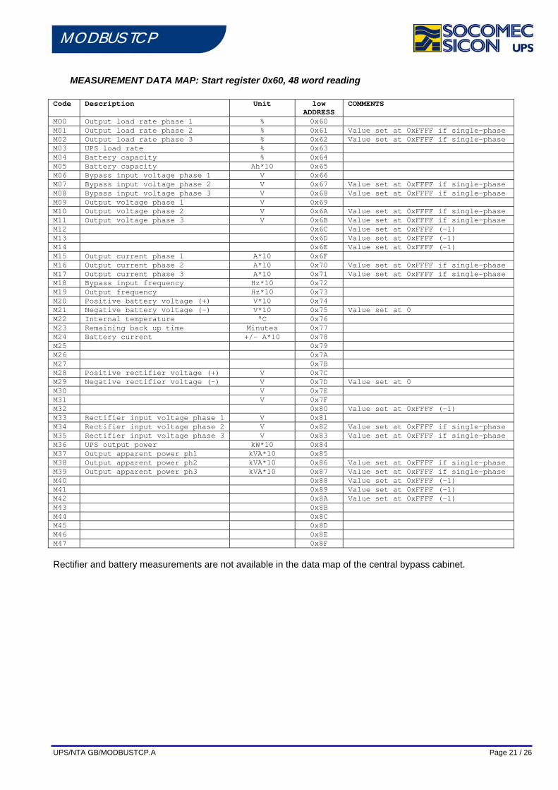
MEASUREMENT DATA MAP: Start register 0x60, 48 word reading Code Description Unit low
ADDRESS COMMENTS
MO0 Output load rate phase 1 % 0x60 M01 Output load rate phase 2 % 0x61 Value set at 0xFFFF if single-phase M02 Output load rate phase 3 % 0x62 Value set at 0xFFFF if single-phase M03 UPS load rate % 0x63 M04 Battery capacity % 0x64 M05 Battery capacity Ah*10 0x65 M06 Bypass input voltage phase 1 V 0x66 M07 Bypass input voltage phase 2 V 0x67 Value set at 0xFFFF if single-phase M08 Bypass input voltage phase 3 V 0x68 Value set at 0xFFFF if single-phase M09 Output voltage phase 1 V 0x69 M10 Output voltage phase 2 V 0x6A Value set at 0xFFFF if single-phase M11 Output voltage phase 3 V 0x6B Value set at 0xFFFF if single-phase M12 0x6C Value set at 0xFFFF (-1) M13 0x6D Value set at 0xFFFF (-1) M14 0x6E Value set at 0xFFFF (-1) M15 Output current phase 1 A*10 0x6F M16 Output current phase 2 A*10 0x70 Value set at 0xFFFF if single-phase M17 Output current phase 3 A*10 0x71 Value set at 0xFFFF if single-phase M18 Bypass input frequency Hz*10 0x72 M19 Output frequency Hz*10 0x73 M20 Positive battery voltage (+) V*10 0x74 M21 Negative battery voltage (-) V*10 0x75 Value set at 0 M22 Internal temperature °C 0x76 M23 Remaining back up time Minutes 0x77 M24 Battery current +/- A*10 0x78 M25 0x79 M26 0x7A M27 0x7B M28 Positive rectifier voltage (+) V 0x7C M29 Negative rectifier voltage (-) V 0x7D Value set at 0 M30 V 0x7E M31 V 0x7F M32 0x80 Value set at 0xFFFF (-1) M33 Rectifier input voltage phase 1 V 0x81 M34 Rectifier input voltage phase 2 V 0x82 Value set at 0xFFFF if single-phase M35 Rectifier input voltage phase 3 V 0x83 Value set at 0xFFFF if single-phase M36 UPS output power kW*10 0x84 M37 Output apparent power ph1 kVA*10 0x85 M38 Output apparent power ph2 kVA*10 0x86 Value set at 0xFFFF if single-phase M39 Output apparent power ph3 kVA*10 0x87 Value set at 0xFFFF if single-phase M40 0x88 Value set at 0xFFFF (-1) M41 0x89 Value set at 0xFFFF (-1) M42 0x8A Value set at 0xFFFF (-1) M43 0x8B M44 0x8C M45 0x8D M46 0x8E M47 0x8F
Rectifier and battery measurements are not available in the data map of the central bypass cabinet.
UPS/NTA GB/MODBUSTCP.A Page 22 / 26
MODBUS TCP
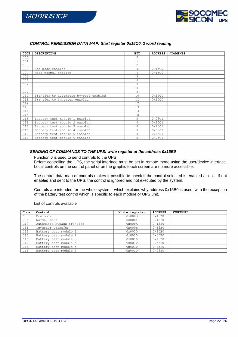
CONTROL PERMISSION DATA MAP: Start register 0x15C0, 2 word reading CODE DESCRIPTION BIT ADDRESS COMMENTS C00 0 C01 1 C02 2 C03 Eco-mode enabled 3 0x15C0 C04 Mode normal enabled 4 0x15C0 C05 5 C06 6 C07 7 C08 8 C09 9 C10 Transfer to automatic by-pass enabled 10 0x15C0 C11 Transfer to inverter enabled 11 0x15C0 C12 12 C13 13 C14 14 C15 15 C16 Battery test module 1 enabled 0 0x25C1 C16 Battery test module 2 enabled 0 0x35C1 C16 Battery test module 3 enabled 0 0x45C1 C16 Battery test module 4 enabled 0 0x55C1 C16 Battery test module 5 enabled 0 0x65C1 C16 Battery test module 6 enabled 0 0x75C1
SENDING OF COMMANDS TO THE UPS: write register at the address 0x15B0 Function 6 is used to send controls to the UPS. Before controlling the UPS, the serial interface must be set in remote mode using the user/device interface. Local controls on the control panel or on the graphic touch screen are no more accessible. The control data map of controls makes it possible to check if the control selected is enabled or not. If not enabled and sent to the UPS, the control is ignored and not executed by the system. Controls are intended for the whole system - which explains why address 0x15B0 is used, with the exception of the battery test control which is specific to each module or UPS unit. List of controls available
Code Control Write register ADDRESS COMMENTS C03 Eco-mode 0x0003 0x15B0 C04 Normal mode 0x0004 0x15B0 C10 Automatic bypass transfer 0x000A 0x15B0 C11 Inverter transfer 0x000B 0x15B0 C16 Battery test module 1 0x0010 0x25B0 C16 Battery test module 2 0x0010 0x35B0 C16 Battery test module 3 0x0010 0x45B0 C16 Battery test module 4 0x0010 0x55B0 C16 Battery test module 5 0x0010 0x65B0 C16 Battery test module 6 0x0010 0x75B0
UPS/NTA GB/MODBUSTCP.A Page 23 / 26
MODBUS TCP
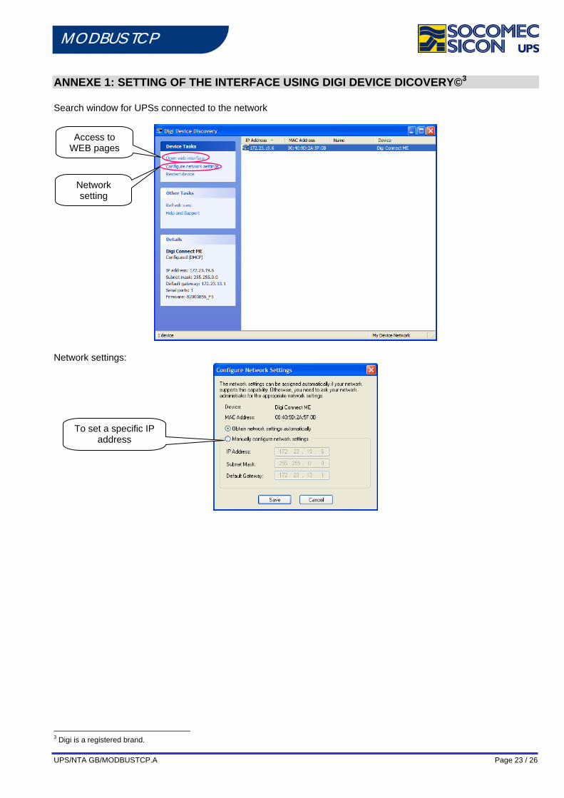
ANNEXE 1: SETTING OF THE INTERFACE USING DIGI DEVICE DICOVERY©3 Search window for UPSs connected to the network
Network settings:
3 Digi is a registered brand.
Access to WEB pages
Network setting
To set a specific IP address
UPS/NTA GB/MODBUSTCP.A Page 24 / 26
MODBUS TCP Access to HTTP pages
Login: root Password: dbps Home Page:
UPS/NTA GB/MODBUSTCP.A Page 25 / 26
MODBUS TCP Updating of the firmware:
Version of firmware:
MODBUS TCP: 82001164.bin REAL PORT: 82000856_F5.bin
Click on
opens an on-line help window and a link to DIGI site if necessary. After completing the downloading process, click on Reboot. Wait for at least 1 minute before trying to access the interface. Problem during downloading process: If the following screen appears during downloading, it is necessary to download the POST version of the firmware (available on the CD) as well as the firmware.
Indicate directory of binary file to be downloaded.
UPS/NTA GB/MODBUSTCP.A Page 26 / 26
MODBUS TCP
ANNEXE 2: MODBUS TCP IDA specification The JBUS frames below are only examples:
REQUEST BY MASTER IN MODE JBUS/MODBUS RTU Original frame: 01 03 1034 0003 40C5 Encapsulated frame: 0046 0000 0006 01 03 1034 0003
where:
0046 corresponds to the transaction number 0000 corresponds to the protocol identifier 0006 corresponds to the number of bytes (length of the message)
Note:
The CRC is suppressed in the encapsulated JBus frame. REPLY OF THE UPS IN MODE JBUS/MODBUS RTU:
Original frame: 01 03 06 0002 0184 0000 1960 Encapsulated frame: 0046 0000 0009 01 03 06 0002 0184 0000
where:
0046 corresponds to the transaction number 0000 corresponds to the protocol identifier 0006 corresponds to the number of bytes (length of the message)
Note:
The CRC is suppressed in the encapsulated JBus frame.


