Document Applicability Anemometer unit Serial numbers 30000 onwards. AC Mains Power Supply Unit Serial numbers 013005 to 013999. DC Low Voltage Power Supply Unit Serial numbers 040001 onwards.
1. FOREWORD ................................................................................................................................................. 5 2. INTRODUCTION ......................................................................................................................................... 5 3. IS SYSTEM PACKING LIST ...................................................................................................................... 5
3.1 Gill Part 1360-PK-022 .......................................................................................................................... 5 3.2 Gill Part 1360-PK-060 .......................................................................................................................... 6 3.3 Spares ..................................................................................................................................................... 6
4. SPECIFICATION .......................................................................................................................................... 7 4.1 Intrinsically Safe WindObserver 1360-PK-052................................................................................... 7 Mounted in Hazardous Area.............................................................................................................................. 7 4.2 Power Supply Unit 1360-PK-053. ........................................................................................................ 8 Mounted in Non Hazardous Area. .................................................................................................................... 8 4.3 Power Supply Unit 1360-PK-055 (1954-00-002) ............................................................................... 9 Mounted in Non Hazardous Area. .................................................................................................................... 9
5. INSTALLATION......................................................................................................................................... 10 5.1 Pre-Installation requirements .............................................................................................................. 10 5.1.1 Installation using a Mains Power Supply. ...................................................................................... 11 Drawing 1360-G-028 I.S. Issue 3, IS WindObserver System Diagram Sheet 1 of 2. ................................. 11 Drawing 1360-G-028 Issue 3, I.S. WindObserver System Diagram Sheet 2 of 2. ...................................... 12 5.1.2 Installation using a Low Voltage Power Supply. .......................................................................... 13 5.2 Installation Guidelines ......................................................................................................................... 15 5.2.1 Power Supply Mains ....................................................................................................................... 15 5.2.2 Power Supply Low Voltage ................................................................................................................... 16 5.2.3 Anemometer ..................................................................................................................................... 17 5.2.4 Cabling ............................................................................................................................................. 19 5.2.5 Mounting .......................................................................................................................................... 21 Drawing 1086-G-045 Issue 2 Anemometer Installation Details ................................................................... 21 5.2.6 Alignment......................................................................................................................................... 22 Drawing 1360-G-026 Issue 1, Type IIc I.S. Anemometer Dimensions ....................................................... 22 5.2.7 Sealing .............................................................................................................................................. 23 5.2.8 Corrosion .......................................................................................................................................... 23 5.2.9 Earthing ............................................................................................................................................ 23 5.2.10 General ............................................................................................................................................ 23
6. SYSTEM OPERATION .............................................................................................................................. 23 6.1 Anemometer Default Settings ............................................................................................................. 23 6.2 IS Power Supply Unit Mains Voltage Default Setting ...................................................................... 24
7. CONNECTION TO A PC OR OTHER DEVICE ..................................................................................... 25 8. USING THE ANEMOMETER WITH A COMPUTER AND SOFTWARE ......................................... 28
8.1 Digital Serial Output Formats ............................................................................................................. 29 8.2 Digital Format Notes ........................................................................................................................... 38 8.3 Status Codes ......................................................................................................................................... 40
10.6.1 Alignment Check. ............................................................................................................................. 52 10.6.2 Connections and tests with the Mains Supply Unit ........................................................................ 52 10.6.3 Connections and tests with the Low Voltage Supply Unit ............................................................ 56
10.7 Returning Units .................................................................................................................................... 59 11. DRAWINGS ............................................................................................................................................ 60
11.1 Mains Power Supply Drawing 1360-M-039 Issue 4, I.S.Terminal Arrangement. .......................... 60 11.2 Mains Power Supply Drawing 1360-G-043 Issue 2 I.S. PCI Unit ................................................... 61 11.3 Low Voltage Power Supply Drawing 1954-30-023 issue 2 Terminal Arrangement. ..................... 62
APPENDIX 1 ....................................................................................................................................................... 63 SUMMARY OF ABBREVIATIONS USED IN THIS MANUAL ............................................................. 63
1. FOREWORD Thank you for purchasing the Gill Instruments Limited Intrinsically Safe WindObserver ultrasonic anemometer system. The Anemometer has no customer serviceable parts and requires no calibration or maintenance. To achieve optimum performance we recommend that you read the whole of this manual before proceeding with use. Do NOT remove the Anemometer black “rubber” transducer caps. Gill products are in continuous development and therefore specifications may be subject to change and design improvements without prior notice. The information contained in this manual remains the property of Gill Instruments and must not be copied or reproduced for commercial gain. Modifications to the Intrinsically Safe WindObserver Anemometer or associated Power Supply unit will invalidate the Approval Certificates and Warranty.
2. INTRODUCTION The Gill Intrinsically Safe WindObserver is a very robust unit with no moving parts, outputting wind speed and direction. The units of wind speed, output rate and formats are all user selectable. The Intrinsically Safe WindObserver can be used in conjunction with a PC, data logger or other device, provided it is compatible with the Power Supply Unit Box which provides the RS232 or RS422 output. The RS422 Output of the Power Supply Unit Box is designed to connect directly to the Gill WindDisplay unit to provide a complete wind speed direction system. The Anemometer output message format can be configured in Polar, UV (2-axis), NMEA (0183 Version 3), tunnel or Binary and as either a Continuous output or Polled (requested by host system), detailed in full in Para 8.1 Digital Serial Output Formats.
3. IS SYSTEM PACKING LIST
3.1 Gill Part 1360-PK-022 Comprising of:-
1360-PK-052 Intrinsically Safe WindObserver 2 axis anemometer. 1255-10-057 Anemometer Mounting kit. 1360-PK-054 Anemometer 20 Way Connector kit. 1000-10-034 This manual on a CD. 1277-30-045 Head Cover (2 halves). 1360-PK-053 Intrinsically Safe Power Supply Unit (and Communications
Interface). Mains Power Supply. 1360-10-008 3 Metre Anemometer Test Cable.
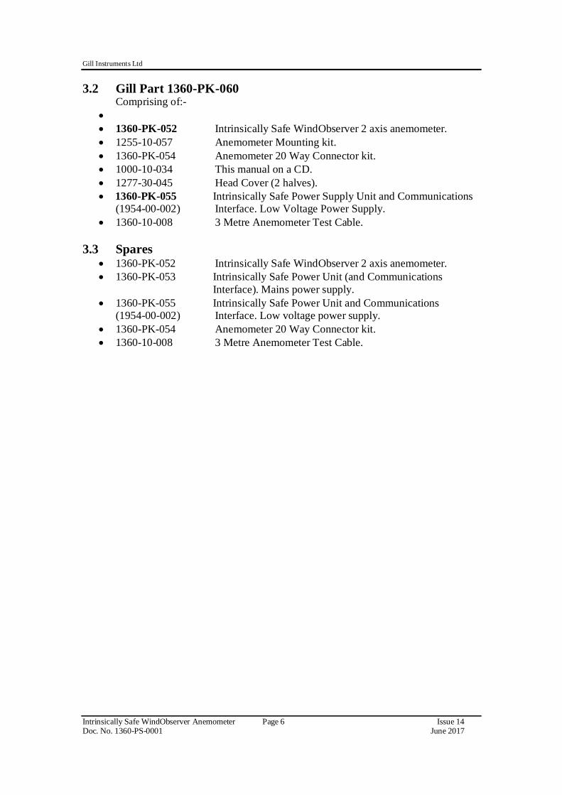
1360-PK-052 Intrinsically Safe WindObserver 2 axis anemometer. 1255-10-057 Anemometer Mounting kit. 1360-PK-054 Anemometer 20 Way Connector kit. 1000-10-034 This manual on a CD. 1277-30-045 Head Cover (2 halves). 1360-PK-055 Intrinsically Safe Power Supply Unit and Communications
(1954-00-002) Interface. Low Voltage Power Supply. 1360-10-008 3 Metre Anemometer Test Cable.
3.3 Spares 1360-PK-052 Intrinsically Safe WindObserver 2 axis anemometer. 1360-PK-053 Intrinsically Safe Power Unit (and Communications
Interface). Mains power supply. 1360-PK-055 Intrinsically Safe Power Unit and Communications
(1954-00-002) Interface. Low voltage power supply. 1360-PK-054 Anemometer 20 Way Connector kit. 1360-10-008 3 Metre Anemometer Test Cable.
Mounted in Hazardous Area. I.S. Rating – ATEX European and IECEx International (For use in Zone 0, 1 and 2 Areas).
See ATEX and IECEx Certificates in Appendix 2. Measurement Output 1, 2 and 4Hz Parameters UV, Polar, NMEA, Tunnel, Binary Units m/s, Knots, MPH, KPH ft/min Averaging Flexible 0 to 3600 seconds or Adjustable averaging (Road Weather Averaging) Wind Speed Range 0 - 75m/s Accuracy ±5% RMS Resolution 0.01m/s Starting Threshold 0.01 m/s Direction Range 0 - 359° Accuracy ± 4° Resolution 1° Dead Band Wind Direction None Note Wind Speed and Direction accuracy apply from +5 deg C to +35 Deg C and for Wind incidence within ± 10° of horizontal. Anemometer Status Supplied as part of standard message Power Requirement Anemometer only, 6V-12VDC, 30mA peak (from Gill
ATEX/IECEX Certified Power and Communications Box only) all circuits protected to 0.8 Joules.
Digital Output Communication RS422, full duplex (to Power and Control Box). Baud rates 1200, 2400, 4800, 9600, 19200. Formats 8 data, odd, even or no parity Dimensions Size See this manual Page 11 for dimensions Weight IS WindObserver 1.9kg. Materials External Construction Stainless Steel 316 Environmental Moisture protection IP66 (NEMA4X) Ambient Operating temperature -30°C to +70°C Storage Temperature -50°C to +75°C Humidity 0% to 100% RH Precipitation 300mm/hr. EMC EN 61000-6-3:2007 EN 61000-6-1:2007 Intrinsic Safety EN60079-0:2012 EN60079-11:2012 EN60079-26:2007 IEC60079-0:2011 Edition 6.0 IEC60079-11:2011 Edition 6.0 IEC60079-26:2006 Edition 2.0 Standards Traceable to UK national standards UK CAA CAP 437 Specification compared to be compliant to this standard Site Calibration None required.
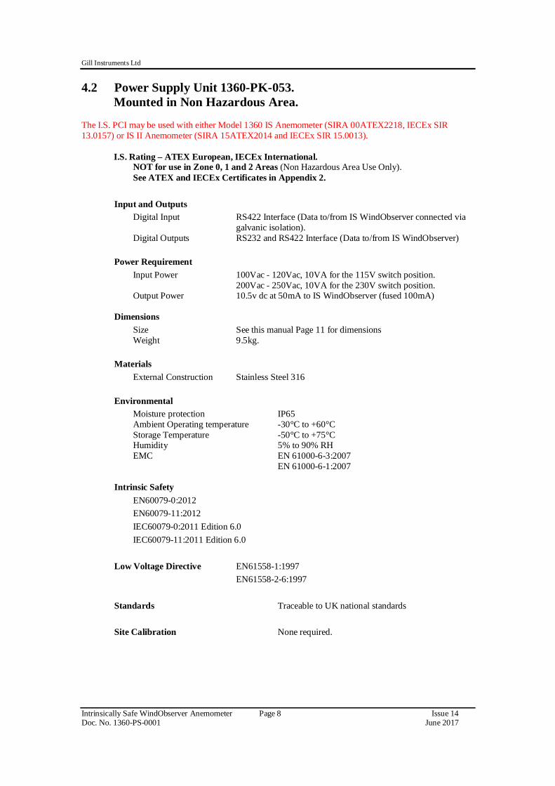
4.2 Power Supply Unit 1360-PK-053. Mounted in Non Hazardous Area.
The I.S. PCI may be used with either Model 1360 IS Anemometer (SIRA 00ATEX2218, IECEx SIR 13.0157) or IS II Anemometer (SIRA 15ATEX2014 and IECEx SIR 15.0013).
I.S. Rating – ATEX European, IECEx International.
NOT for use in Zone 0, 1 and 2 Areas (Non Hazardous Area Use Only). See ATEX and IECEx Certificates in Appendix 2. Input and Outputs Digital Input RS422 Interface (Data to/from IS WindObserver connected via
galvanic isolation). Digital Outputs RS232 and RS422 Interface (Data to/from IS WindObserver) Power Requirement
Input Power 100Vac - 120Vac, 10VA for the 115V switch position. 200Vac - 250Vac, 10VA for the 230V switch position.
Output Power 10.5v dc at 50mA to IS WindObserver (fused 100mA) Dimensions Size See this manual Page 11 for dimensions Weight 9.5kg. Materials External Construction Stainless Steel 316 Environmental Moisture protection IP65 Ambient Operating temperature -30°C to +60°C Storage Temperature -50°C to +75°C Humidity 5% to 90% RH EMC EN 61000-6-3:2007 EN 61000-6-1:2007 Intrinsic Safety EN60079-0:2012 EN60079-11:2012 IEC60079-0:2011 Edition 6.0 IEC60079-11:2011 Edition 6.0 Low Voltage Directive EN61558-1:1997 EN61558-2-6:1997 Standards Traceable to UK national standards Site Calibration None required.
4.3 Power Supply Unit 1360-PK-055 (1954-00-002) Mounted in Non Hazardous Area.
I.S. LVPCI may be used with either Model 1360 IS Anemometer (SIRA 00ATEX2218, IECEx SIR 13.0157) or IS II Anemometer (SIRA 15ATEX2014 and IECEx SIR 15.0013).
I.S. Rating – ATEX European, IECEX International.
NOT for use in Zone 0, 1 and 2 Areas (Non Hazardous Area Use Only). See ATEX and IECEX Certificates in Appendix 2. Input and Outputs Digital Input RS422 Interface (Data to/from IS WindObserver connected via
galvanic isolation). Digital Outputs RS232 and RS422 Interface (Data to/from IS WindObserver) Power Requirement
Input Power 9v to 30v dc at 200mA max (Fused 20mm, 1 amp, anti-surge). Galvanic isolation between input power and anemometer supply.
Output Power 10.5v dc at 50mA to IS WindObserver (fused 100mA) Dimensions Size See page 13 for dimensions. Weight 2.4kg. Materials External Construction Fibox Euronord Polyester Environmental Moisture protection IP54 Ambient Operating temperature -30°C to +60°C Storage Temperature -50°C to +75°C Humidity 5% to 90% RH EMC Emissions and Immunity EN 61326-2-1:2013 EN 61204-3:2000 Emissions EN 60945:2002 Clause 9 Immunity EN 60945:2002 Clause 10 Intrinsic Safety EN60079-0:2012 EN60079-11:2012 EN60079-26:2007 IEC60079-0:2011 Edition 6.0 IEC60079-11:2011 Edition 6.0 IEC60079-26:2006 Editions 2.0 Standards Traceable to UK national standards Site Calibration None required.
5. INSTALLATION 5.1 Pre-Installation requirements Host system - One or more of the following:
PC with an internal or external interface compatible with the RS422 or RS232 output from the Intrinsically Safe WindObserver Power Supply Interface Box.
Gill WindDisplay. Other equipment with I/O compatibility to the Intrinsically Safe WindObserver
System. Software - One of the following:
Gill Wind Software used as a Terminal program only (Wizard and Sync Comms not applicable). Wind will run on PC’s up to and including Windows 10 and can be downloaded free from:- http://www.gillinstruments.com/main/software.html
Other Terminal software packages e.g. HyperTerminal, Tera Term, etc. Use the above Software to configure the IS WindObserver system for the installation.
Cable and Junction Box Installation and wiring to/from the PCI must be carried out in accordance with IEC 60079-14. The Intrinsically Safe WindObserver has a base mounted 20 way socket and is supplied with a mating 20 way connector requiring connection to a suitable IS cable. Intrinsically Safe Cable and Junction Boxes are not available from Gill Instruments and must be determined to be suitable for use by the customer. IS cable resistance must not exceed 17 ohms in each cable wire run. E.g. If using 24 awg wire with cable resistance of 0.08 ohms per metre then maximum cable run is 213 Metres. If using 22 awg wire with cable resistance of 0.05 ohms per metre then maximum cable run is 340 Metres. It is advised that the installed cable is retained with a cable tie within 150mm of the base of the anemometer. A 3 metre test cable is supplied with the IS System to enable system testing and configuration to be carried out. Mounting The Intrinsically Safe WindObserver can be attached to a mount as detailed in Drawing 1086-G-045 on page 21. Always ensure that the gasket supplied is fitted to the base of the anemometer mount. It is important that the gasket supplied forms a watertight seal on the base of the anemometer. The Mains Powered Power Supply Unit mounting details are as per drawing 1360-G-028 on page 11. Lid screws should be torqued to 2Nm, Gland Plate screws to 4Nm and Earth stud to 10Nm. The Low Voltage Power Supply Unit mounting details are as per drawing 1954-30-026. Earthing Ensure that the IS Anemometer and Power Supply Unit are Earthed via the Earth terminal provided on the equipments in accordance with the Local or National regulations.
5.1.1 Installation using a Mains Power Supply. The unit must be installed in accordance with the Control Drawing 1360-G-028. Note that the PCI box is mounted in the Non Hazardous area. Drawing 1360-G-028 I.S. Issue 3, IS WindObserver System Diagram Sheet 1 of 2. Power Supply Lid screws should be torqued to 2Nm, Gland Plate screws to 4Nm and Earth stud to 10Nm.
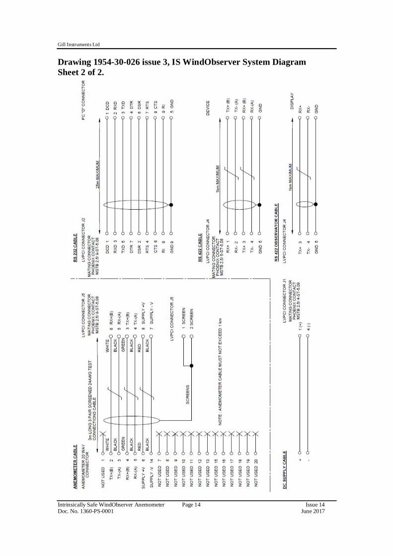
5.1.2 Installation using a Low Voltage Power Supply. The unit must be installed in accordance with the Drawing 1954-30-026. Note that the PCI box is mounted in the Safe area. Drawing 1954-30-026 issue 3, IS WindObserver System Diagram Sheet 1 of 2.
5.2 Installation Guidelines 5.2.1 Power Supply Mains Instructions specific to hazardous area installations (in accordance with IEC60079-0:2011 clause 30) The following instructions relevant to safe use in a hazardous area apply to equipment covered by certificate numbers IECEx SIR 13.0156 and Sira 00ATEX2217.
1. The certification marking is as follows: Certificate number: IECEx SIR 13.0156 Sira 00ATEX2217 Certification code: [Ex ia Ga] IIC
[Ex ia Da] IIIC [Ex ia Ga] IIC [Ex ia Da] IIIC
Other marking: (Ta = -30⁰C to +60⁰C) 0518
II(1)GD 2. The equipment may only be used in non-hazardous area.
3. The equipment is only certified for use in ambient temperatures in the range
-30ºC to +60ºC and should not be used outside this range.
4. Installation shall be carried out in accordance with the applicable code of practice by suitably-trained personnel.
5. There are no special checking or maintenance conditions other than a periodic check.
6. With regard to explosion safety, it is not necessary to check for correct operation.
7. The equipment contains no user-replaceable parts and is not intended to be repaired by the user. Repair of the equipment is to be carried out by the manufacturer, or their approved agents, in accordance with the applicable code of practice.
8. Repair of this equipment shall be carried out in accordance with the applicable code of practice.
9. If the equipment is likely to come into contact with aggressive substances, e.g. acidic liquids or gases that may attack metals or solvents that may affect polymeric materials, then it is the responsibility of the user to take suitable precautions that prevent it from being adversely affected thus ensuring that the type of protection is not compromised.
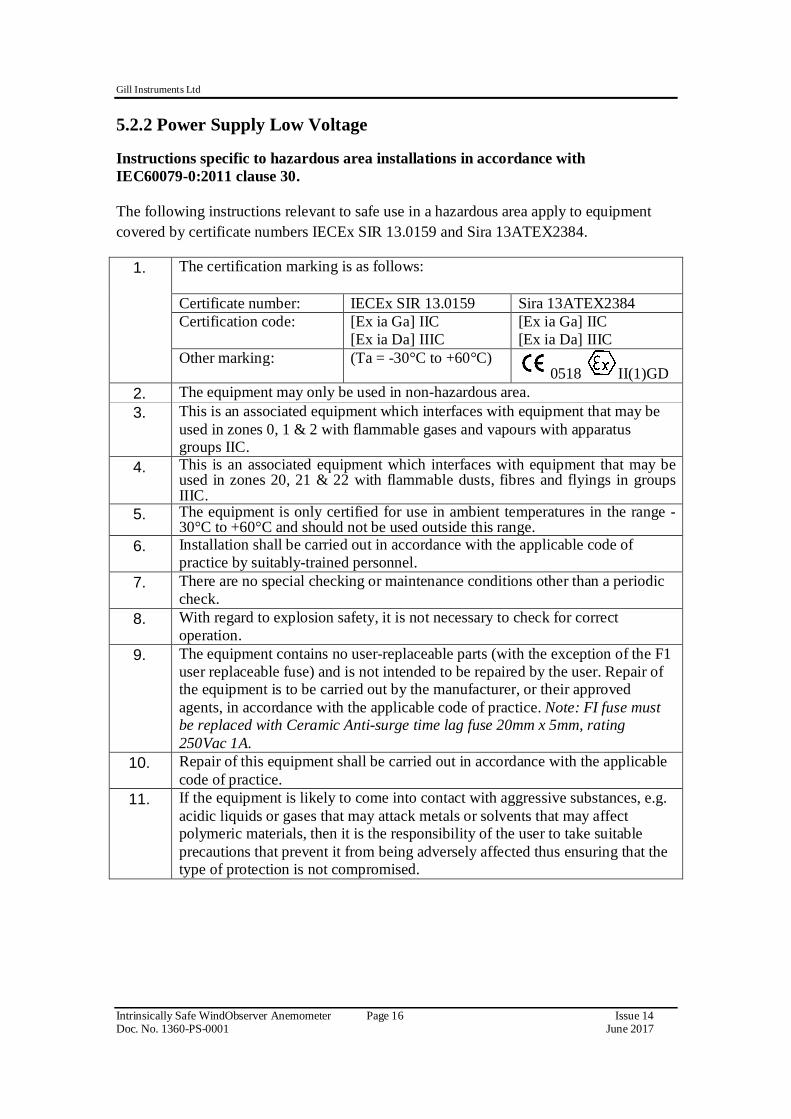
5.2.2 Power Supply Low Voltage Instructions specific to hazardous area installations in accordance with IEC60079-0:2011 clause 30. The following instructions relevant to safe use in a hazardous area apply to equipment covered by certificate numbers IECEx SIR 13.0159 and Sira 13ATEX2384.
1. The certification marking is as follows:
Certificate number: IECEx SIR 13.0159 Sira 13ATEX2384 Certification code: [Ex ia Ga] IIC
[Ex ia Da] IIIC [Ex ia Ga] IIC [Ex ia Da] IIIC
Other marking: (Ta = -30°C to +60°C) 0518 II(1)GD
2. The equipment may only be used in non-hazardous area. 3. This is an associated equipment which interfaces with equipment that may be
used in zones 0, 1 & 2 with flammable gases and vapours with apparatus groups IIC.
4. This is an associated equipment which interfaces with equipment that may be used in zones 20, 21 & 22 with flammable dusts, fibres and flyings in groups IIIC.
5. The equipment is only certified for use in ambient temperatures in the range -30°C to +60°C and should not be used outside this range.
6. Installation shall be carried out in accordance with the applicable code of practice by suitably-trained personnel.
7. There are no special checking or maintenance conditions other than a periodic check.
8. With regard to explosion safety, it is not necessary to check for correct operation.
9. The equipment contains no user-replaceable parts (with the exception of the F1 user replaceable fuse) and is not intended to be repaired by the user. Repair of the equipment is to be carried out by the manufacturer, or their approved agents, in accordance with the applicable code of practice. Note: FI fuse must be replaced with Ceramic Anti-surge time lag fuse 20mm x 5mm, rating 250Vac 1A.
10. Repair of this equipment shall be carried out in accordance with the applicable code of practice.
11. If the equipment is likely to come into contact with aggressive substances, e.g. acidic liquids or gases that may attack metals or solvents that may affect polymeric materials, then it is the responsibility of the user to take suitable precautions that prevent it from being adversely affected thus ensuring that the type of protection is not compromised.
5.2.3 Anemometer Instructions specific to hazardous area installations (in accordance with IEC60079-0:2011 clause 30) The following instructions relevant to safe use in a hazardous area apply to equipment covered by certificate numbers IECEx SIR 15.0013 and SIRA 15ATEX2014.
1. The certification marking is as follows: Certificate number: IECEx SIR 15.0013 SIRA 15ATEX2014 Certification code: Ex ia IIC T4 Ga
Ex ia IIIC T135°C Da IP66 Ex ia IIC T4 Ga Ex ia IIIC T135°C Da IP66
Other marking: (Ta = -30⁰C to +70⁰C) 0518 II 1 GD
2. The equipment may be used in zones 0, 1 & 2 with flammable gases and vapours with apparatus groups IIA, IIB & IIC and with temperature classes T4.
3. The equipment is only certified for use in ambient temperatures in the range -30ºC to +70ºC and should not be used outside this range.
4. The equipment may be used in zones, 20, 21 & 22 with flammable dusts, fibres and flyings in groups IIIA, IIIB and IIIC, T135ºC.
5. Installation shall be carried out in accordance with the applicable code of practice by suitably-trained personnel.
6. There are no special checking or maintenance conditions other than a periodic check.
7. With regard to explosion safety, it is not necessary to check for correct operation.
8. The equipment contains no user-replaceable parts and is not intended to be repaired by the user. Repair of the equipment is to be carried out by the manufacturer, or their approved agents, in accordance with the applicable code of practice.
9. Intrinsically Safe operation is strictly dependant on the use of approved power supplies and maximum cable lengths lying within the limits recommended in the manual.
10. If the equipment is likely to come into contact with aggressive substances, e.g. acidic liquids or gases that may attack metals or solvents that may affect polymeric materials, then it is the responsibility of the user to take suitable precautions that prevent it from being adversely affected thus ensuring that the type of protection is not compromised.
Anemometer Siting General Guidelines The Intrinsically Safe WindObserver has been designed to meet and exceed the stringent standards listed in its specification. Operating in diverse environments all over the world, Intrinsically Safe WindObserver requires no calibration or adjustment whatsoever. As with any sophisticated electronics, good engineering practice should be followed to ensure correct operation. Always check the installation to ensure the Intrinsically Safe WindObserver is not affected by other equipment operating locally, which may not conform to current standards, e.g. radio/radar transmitters, boat engines, generators etc. Guidelines should any of the following be encountered:-
Avoid mounting in the plane of any radar scanner – a vertical separation of at least 2m should be achieved. Radio transmitting antennas, the following minimum separations (all round) are suggested
Ensure the product is correctly earthed in accordance with this manual Use cables recommended for the IS installation, keeping the length below the maximum allowed (see Pages 19 to 27). Where the cables are cut and re-connected (junction boxes, plugs and sockets) the cable screen integrity must be maintained, to prevent the EMC performance being compromised. Earth loops should not be created – earth the system in accordance with the installation guidelines. Ensure the power supply operates to the Intrinsically Safe WindObserver specification at all times. Avoid positioning where gas flare stack temperatures in surrounding air exceed unit operating limits. Avoid turbulence caused by surrounding structures that will affect the accuracy of the Intrinsically Safe WindObserver such as trees, masts and buildings. The World Meteorological Organisation makes the following recommendation: The standard exposure of wind instruments over level open terrain is 10m above the ground. Open terrain is defined as an area where the distance between the sensor and any obstruction is at least 10 times the height of the obstruction. When installing the unit degrease the unit and hold with lint free gloves to reduce the build-up of deposits.
5.2.4 Cabling Installation and wiring to/from the PCI must be carried out in accordance with IEC 60079-14. Anemometer The Intrinsically Safe WindObserver and Power Supply Interface Box is supplied with a 3-Metre long, 3 pair, 24 AWG, screened, 8mm ± 0.2mm diameter test cable connected to a 20 way Hirose connector at one end and stripped wires at the other. A 20 way connector kit is supplied with the Anemometer to connect to customer supplied cable. The customer supplied cable between the Anemometer and the Power Supply Box should be a 3 pair twisted, screened and / or armoured, and have a minimum of 0.75mm cross sectional area and a maximum of 2.5mm cross sectional area. The cable should meet the Cable Parameter requirements of the Sira Certificate in Appendix 2 and IECEx Certificate in Appendix 2. Do not attach the screen of the anemometer to earth at the junction box; it must be attached to cable screen terminals in the PCI box via the field cable screen. If armoured cable is used the armour must be connected to earth. DO NOT join the cable armour to the screen.
Cable length IS cable resistance must not exceed 17 ohms in each cable wire run. E.g. If using 24 awg wire with cable resistance of 0.08 ohms per metre then maximum cable run is 213 Metres. If using 22 awg wire with cable resistance of 0.05 ohms per metre then maximum cable run is 340 Metres. It is advised that the installed cable is retained with a cable tie within 150mm of the base of the anemometer. If any problems of data corruption are experienced (due to, for example, a high local electrical ‘noise’ level), then a lower baud rate should be used. Alternatively, a thicker or higher specification cable can be tried. Ensure that strain relief measures are employed when installing the cables. Do not allow the whole weight of the cable to be applied to the connector. Note: Gill Instruments do not supply Intrinsically Safe cables; it is the responsibility of the customer to determine the type of cable that is suitable for each individual IS installation. Connector Assembly. The IS WindObserver is supplied with a mating 20 way connector. Open the pack of connector parts supplied (Gill Part 1360-PK-054).
Table of Equivalent Part Numbers Part Name Gill Part No. Hirose Part No.
Connector plug, 20 way 020-02673 RM21WTP20P71 Extended backshell 1284-30-006 Not Available Cord Clamp 8mm 020-02872 JR13WCCA-8(72)
20 Way Connector terminal positions viewed from the solder connection side. Wiring Connections between the 20 way Anemometer connector and the Power Supply Interface Box.
20 Way Connector
Pin Number
Mains Power Supply Terminal
Number
Low Voltage Supply J5 Terminal
Number
Anemometer Function
2 24 6 TX+ RS422 Transmit Data to the Power Box
3 23 5 TX- RS422 Transmit Data to the Power Box
4 21 3 RX+ RS422 Receive Data to the Anemometer
5 22 4 RX- RS422 Receive Data to the Anemometer
6 26 8 Supply +ve 14 25 7 Supply –ve - 19 or 20 1 or 2 Cable Screen
Arrange IS WindObserver Connector Parts as Follows.
Align the 20 way plug rotatable ring to allow access of a jeweller’s screwdriver to
remove the miniature grub screw. Fit parts over the IS cable in the order shown above. Prepare IS cable for soldering wires to the 20 way connector. Solder wires to contacts as per the above table. Screw the extended backshell into the connector (ensure that a sealing ring is
fitted internally) and tighten to a torque of 3Nm Align the connector ring to allow re-fitting of the grub screw to a torque of 0.2 to
5.2.5 Mounting Do NOT remove the black “rubber” transducer caps. Take care not to knock the four transducer arms. All the time the WindObserver is not in its final location, it should be protected from damage by keeping it in its original packaging, treating it as a delicate instrument. When transporting the Anemometer from its box to its install location the supplied head cover parts (1277-30-045) should be fitted around the anemometer head (see below) and secured in place using supplied Tyraps. Upon install completion remove the head cover. The Anemometer should be mounted on a suitable surface as defined in drawing 1086-G-045 shown below, using the mounting kit supplied and described in the Packing List. Warranty and Certification is void if the case is removed. Drawing 1086-G-045 Issue 2 Anemometer Installation Details .
IS WindObserver Head showing application of protective head cover (Part/s 1277-30-045).
5.2.6 Alignment The anemometer should be set to point North, see drawing 1360-G-026 as shown below, (or to some other known reference direction). This is facilitated by slots in the base for the mounting screws, which allow rotation of the anemometer for fine alignment.
Drawing 1360-G-026 Issue 1, Type IIc I.S. Anemometer Dimensions
5.2.7 Sealing The connector area at the base of the anemometer should not be directly exposed to moisture or solvents, as whilst the connectors are sealed when mated, the anemometer is vented to air at the base to avoid pressure build up. Therefore use the gasket provided in the mounting kit.
5.2.8 Corrosion Careful note should be taken of the possibility of galvanic corrosion by incorrect mounting. It is vital that only stainless steel fixings are used and that the instrument is insulated from the mounting surface with the rubber gasket. This will ensure that the anemometer will provide long service under extreme conditions.
5.2.9 Earthing The system must be earthed in accordance with local or national regulations. Intrinsically safe operation will be affected if incorrectly earthed. An Earth terminal is located at the base of the IS Anemometer and to ensure correct operation, and for maximum protection against lightning, the anemometer MUST be correctly earthed (grounded) via its mountings. Inadequate Earthing will degrade anemometer performance, particularly in the presence of radio frequency interference. 5.2.10 General DO NOT attempt to remove or unscrew any fixing. Any unauthorised adjustment of the unit could affect intrinsic safety and will void the warranty. User modifications to the PCB are not permissible and will invalidate the Approval Certificates and Warranty. 6. SYSTEM OPERATION
6.1 Anemometer Default Settings The factory default settings are:-
B3 F1 G0000 K1 L1 M2 NA O1 P1 U1 V1 X1 (Refer to Para 9.2 for a full explanation of the available settings).
B3: 9600 baud. F1: 8 bits, no parity, 1 stop bit. G0000 No averaging. K1 IIMWV NMEA prefix. L1 CR, LF. M2 Polar ASCII continuous data. NA Node address A. O1 Commas Separated Variable Output. P1 1 output per second. U1 Metres/Second. V1 Vertical padding disabled. X1 Align U axis with the transducer axis.
6.2 IS Power Supply Unit Mains Voltage Default Setting The IS Mains Operated Power Supply Unit is shipped set for 230v AC operation and will not self-adjust for 115 AC operation. If 115v AC operation is required then set the internal slide switch to the 115V setting. Changing the supply voltage may be accomplished by first ensuring mains power is not applied to the Power Supply box. Open the Power Supply box lid. Remove 4 screws and washers retaining the protective Perspex cover over the PSU pcb. Remove the Perspex cover and then set the slide switch to the appropriate voltage position. Reverse the above to re-assemble the unit the lid screws should be torqued to 2NM.
7. CONNECTION TO A PC OR OTHER DEVICE Connection to a PC or other device requires the use of: 1) The specified Intrinsically Safe Power Supply Unit Interface – MUST BE USED UNDER ALL CIRCUMSTANCES, CERTIFICATION AND PREVENTION OF DAMAGE TO THE ANEMOMETER DEPENDS UPON THIS. 2) Power Supply Interface to PC / Other device cable – e.g. Digital RS232 9 way “D Type” connector. The IS Power Supply Unit supplies power to the anemometer electronics and provides conversion of the RS422 signal sent by the anemometer to a RS422 or RS232 signal for a PC. An RS422 or RS232 to USB converter may be required to interface with some PC’s. The anemometer outputs wind data through a single 20 way circular connector in the base. Details of the pin allocations can be found on Page 20. Data is provided in Digital format.
Connecting to a PC or External Device using the RS422 Output Maximum suggested RS422 approved twisted pair screened cable length is 1000 Metres.
RS422 Connections on the 1360 Mains Power Supply Box (see also Para 11.1). Note: In case of communication problems when using RS422 to configure the WindObserver IS Anemometer, a wire link can be fitted between terminals 5 & 19.
Intrinsically Safe Mains Power Supply Box
PC or Device with RS422 Input
Signal Name Mains PSU Terminal Signal Name TX + 3 RX+ TX - 4 RX- RX + 1 TX + RX - 2 TX - GND 5 Ground Earth
CHASSIS 19 - RS422 Connections on the 1954 Low Voltage Power Supply Box (see also Para 11.3).
Connecting to a PC or External Device using the RS232 Output Maximum suggested RS232 approved screened cable length is 25 Metres. RS232 Connections on the Mains Power Supply Box (see also Para 11.1)
Intrinsically Safe Mains Power Supply Box
PC 9 way Connector Serial Port Input
RS232 Signal Name Mains PSU Terminal
Terminal Number
RXD 11 2 TXD 12 3 GND 14 5 (GND)
R232 Connections on the Low Voltage Power Supply Box see also Para 11.3).
Connecting to a Gill WindDisplay using an RS422 Connection (see also Para 11.1 and Para 11.3). Maximum suggested RS422 approved twisted pair screened cable length is 1000 Metres. Refer to the WindDisplay User Manual for the method of operation.
Intrinsically Safe Power Supply Box WindDisplay Signal Name
The Intrinsically Safe WindObserver is designed to interface with the Gill WindDisplay unit via the Power Supply Interface to provide a complete wind speed and direction system. To interface to a non NMEA WindDisplay the WindObserver is set for Polar (M2) and 9600 (B3) configuration settings.
When coupled to a WindDisplay, the Intrinsically Safe WindObserver can be used as supplied, however if a fault occurs the WindDisplay may lock into the last valid reading. Re-configuring the Intrinsically Safe WindObserver to Fixed Field output (O2) will ensure that any fault is flagged on the WindDisplay.
After coupling to a WindDisplay, the Wind Speed units and the Averaging period can be selected using the WindDisplay controls. See the WindDisplay User Manual.
Note that although the WindDisplay can display wind speed in various units, these are calculated within the WindDisplay. The data coming to the WindDisplay must be in metres/sec (the IS WindObserver factory default output setting).
Meteorological Display Marine Display NOTES:-
If the WindDisplay is configured for NMEA mode then the Intrinsically Safe WindObserver must also be configured for NMEA mode and normally 4800 baud operation (configuration settings M5 and B2).
The WindDisplay cannot provide power for the sensor circuitry.
8. USING THE ANEMOMETER WITH A COMPUTER AND SOFTWARE This section describes the modes and format of the data output by the anemometer. Use only the approved Gill Instruments IS Supply otherwise damage is likely to occur to the Anemometer and invalidate certification. On first applying power to the WindObserver, it will be in ‘Measurement Mode’, and it will output wind measurement information within 3 seconds in one of the formats as described below. Setting the output format, units, other parameters, options and the communication settings are all carried out in the alternative ‘Configuration Mode’. See Section 9 Anemometer Software Commands for details of how this is done. The factory default settings are shown here in bold, and for convenience some ‘Configuration codes’ (as used to set the configuration) are shown in blue boxes. For example M3.
Wind Speed format The wind speed measurements can be output in one of the following formats: UV, Polar, Customer formats (NMEA, Tunnel and Binary).
Output formats The UV and Polar wind speed parameters are output in either ASCII or binary. These parameters can be transmitted continuously or polled from the user. Polar is also available in continuous NMEA format. Output Formats Table Output format Output Tri-state o/p Configuration code
ASCII UV Continuous No M1
Polled Yes M3
ASCII Polar Continuous No M2 Polled Yes M4
ASCII Tunnel Continuous No M12 ASCII Tunnel Polled Yes M13 NMEA Continuous No M5 Binary Tunnel Continuous No M6
Binary UV short Continuous No M7 Binary Polar Continuous No M8
8.1 Digital Serial Output Formats The following data modes are available from the serial output of the anemometer:- Mode 1 ASCII, UV, Continuous A,+000.00,+000.01,M,00,21 Fault free conditions. A,,,M,04,24 Fault report condition with CSV setting (O1). A,+999.99,+999.99,M,04,24 Fault report condition with Fixed Field setting (O2). Where: <STX><ID>,±UUU.UU,±VVV.VV,U,SS,<ETX>CC<CR><LF> where: <STX> - Start of string character (ASCII value 2) <ID> - Anemometer IDentification (A-Z) ±UUU.UU - ‘U’ axis velocity (*1) ±VVV.VV - ‘V’ axis velocity (*2) U - Units (M=m/s, N=knots, P=mph, K=kph, F=fpm) SS - Status Code (see Para 10.5) <ETX> - End of string character (ASCII value 3) CC - Checksum of all Characters between <STX> and <ETX>
(HEX byte) <CR><LF> - Carriage Return and LineFeed
(*1) In Feet per Minute output mode, the string changes to ±UUUU.U (*2) In Feet per Minute output mode, the string changes to ±VVVV.V
Mode 2 ASCII, Polar, Continuous A,279,000.05,M,00, 07 Fault free conditions. A,,,M,04,24 Fault report condition with CSV setting (O1). A,999,999.99,M,04,0A Fault report condition with Fixed Field setting (O2). Where: <STX><ID>,DDD,MMM.MM,U,SS,<ETX>CC<CR><LF> where: <STX> - Start of string character (ASCII value 2) <ID> - Anemometer IDentification (A-Z) DDD - Direction in degrees MMM.MM - Wind Magnitude (*3) U - Units (M=m/s, N=knots, P=mph, K=kph, F=fpm) SS - Status Code (see Para 10.5) <ETX> - End of string character (ASCII value 3) CC - Checksum of all Characters between <STX> and <ETX>
(HEX byte) <CR><LF> - Carriage Return and LineFeed
(*3) In Feet per Minute output mode, the string changes to MMMM.M
Mode 3 ASCII, UV, Polled (Point to Point only) A,+000.00,+000.01,M,00,21 Fault free conditions. A,,,M,04,24 Fault report condition with CSV setting (O1). A,+999.99,+999.99,M,04,24 Fault report condition with Fixed Field setting (O2). Where: <STX><ID>,±UUU.UU,±VVV.VV,U,SS,<ETX>CC<CR><LF> <STX> - Start of string character (ASCII value 2) <ID> - Anemometer IDentification (A-Z) ±UUU.UU - ‘U’ axis velocity (*1) ±VVV.VV - ‘V’ axis velocity (*2) U - Units (M=m/s, N=knots, P=mph, K=kph, F=fpm) SS - Status Code (see Para 10.5) <ETX> - End of string character (ASCII value 3) CC - Checksum of all Characters between <STX> and <ETX>
(HEX byte) <CR><LF> - Carriage Return and LineFeed
(*1) In Feet per Minute output mode, the string changes to ±UUUU.U (*2) In Feet per Minute output mode, the string changes to ±VVVV.V
Mode 4 ASCII, Polar, Polled (point to Point only) A,279,000.05,M,00, 07 Fault free conditions. A,,,M,04,24 Fault report condition with CSV setting (O1). A,999,999.99,M,04,0A Fault report condition with Fixed Field setting (O2). Where: <STX><ID>,DDD,MMM.MM,U,SS,<ETX>CC<CR><LF> <STX> - Start of string character (ASCII value 2) <ID> - Anemometer IDentification (A-Z) DDD - Direction in degrees MMM.MM - Wind Magnitude (*3) U - Units (M=m/s, N=knots, P=mph, K=kph, F=fpm) SS - Status Code (see Para 10.5) <ETX> - End of string character (ASCII value 3) CC - Checksum of all Characters between <STX> and <ETX>
(HEX byte) <CR><LF> - Carriage Return and LineFeed
(*3) In Feet per Minute output mode, the string changes to MMMM.M
Mode 5 ASCII, NMEA, continuous $IIMWV,262,R,000.84,M,A*1A Fault free conditions. $IIMWV,,R,,M,V*29 Fault report condition with CSV setting (O1). $IIMWV,999,R,999.99,M,V*07 Fault report condition with Fixed Field setting (O2). Where: $IIMWV,DDD1,R,MMM.MM,U,A,*cc<CR><LF> ‘$’ - Start of string character ‘II’ - Integrated instrument (or WI = Wind Instrument) ‘MWV’ - Mean wind direction and velocity DDD - Direction in degrees ‘R’ - Relative wind measurement MMM.MM Wind Speed U - Units (M=m/s, N=knots, P=mph, K=kph, F=fpm) A - Data Status flag (A = Acceptable, V = Void) ‘*’ - Checksum delimiter cc Checksum, Exclusive OR of all characters between ‘$’ and
‘*’ reported as ASCII hex. MODE 6 Binary Tunnel Continuous In a terminal program the Binary output will look like:-
Converted it will read like:- 0x81 0x81 +000.04 1 00 1 <STX>,MMM.MM, P,SS,U<ETX><CR><LF> Where:- <STX> - Start of string character (ASCII value 2) MMM.MM - Wind Magnitude along U axis. P Direction along U Axis (1 - +U, 0 = -U) SS - Status Code (see Para 10.5) U - Units (1=m/s, 2=knots, 3=mph, 4=kph, 5=fpm) <ETX> - End of string character (ASCII value 3) <CR><LF> - Carriage Return and LineFeed
Mode 7 Binary UV Short Continuous In a terminal program the Binary output will look like:-
Converted it will read like:- 0x81 0x81 +000.04 -000.02 00 1 <STX>,UUU.UU, VVV.VV,SS,U<ETX><CR><LF> Where:- <STX> - Start of string character (ASCII value 2) UUU.UU - Wind Magnitude along U axis. VVV.VV - Wind Magnitude along V axis. SS - Status Code (see Para 10.5) U - Units (1=m/s, 2=knots, 3=mph, 4=kph, 5=fpm) <ETX> - End of string character (ASCII value 3) <CR><LF> - Carriage Return and LineFeed Mode 8 Binary Polar Continuous In a terminal program the Binary output will look like:-
Converted it will read like:- 0x81 0x81 006.04 265 00 1 <STX>,MMM.MM, DDD,SS,U<ETX><CR><LF> Where:- <STX> - Start of string character (ASCII value 2) MMM.MM - Wind Magnitude along U axis. DDD - Wind Magnitude along V axis. SS - Status Code(see Para 10.5) U - Units (1=m/s, 2=knots, 3=mph, 4=kph, 5=fpm) <ETX> - End of string character (ASCII value 3) <CR><LF> - Carriage Return and LineFeed Mode 12 ASCII Tunnel Continuous A,000.00,1,00,M,0F Fault free conditions. A,,1,04,M,15 Fault report condition with CSV setting (O1). A,999.99,1,04,M,02 Fault report condition with Fixed Field setting (O2). <STX>,ID,MMM.MM, P,SS,U<ETX><CR><LF> Where:- <STX> - Start of string character (ASCII value 2) <ID> - Anemometer IDentification (A-Z) MMM.MM - Wind Magnitude along U axis. P Direction along U Axis (1 - +U, 0 = -U) SS - Status Code (see Para 10.5) U - Units (M=m/s, N=knots, P=mph, K=kph, F=fpm) <ETX> - End of string character (ASCII value 3) <CR><LF> - Carriage Return and LineFeed
Mode 13 ASCII Tunnel Polled (point to Point only) A,000.00,1,00,M,0F Fault free conditions. A,,1,04,M,15 Fault report condition with CSV setting (O1). A,999.99,1,04,M,02 Fault report condition with Fixed Field setting (O2). <STX>,ID,MMM.MM, P,SS,U<ETX><CR><LF> Where:- <STX> - Start of string character (ASCII value 2) <ID> - Anemometer IDentification (A-Z) MMM.MM - Wind Magnitude along U axis. P Direction along U Axis (1 - +U, 0 = -U) SS - Status Code(see Para 10.5) U - Units (M=m/s, N=knots, P=mph, K=kph, F=fpm) <ETX> - End of string character (ASCII value 3) <CR><LF> - Carriage Return and LineFeed Mode 14 ASCII Polar Polled (Point to Pont only) Road Weather Average (RWA) A,M14,000,000.00,M,000,000.00,51,40 Poll result upon unit start up whilst building
up an average (Status code 51 reported). A,M14,009,000.02,M,029,000.06,00,42 Poll result when average building completed
(Status code 00 reported). A,M15,000,000.02,M,000,000.06,04,45 CSV data, fault condition (status code 04) A,M15,000,000.03,M,,,04,6C CSV data with fault condition remaining A,M15,,,M,,,04,41 CSV data with continuous fault condition A,M15,296,000.01,M,174,000.08,04,47 Fixed Field, fault condition (status code 04) A,M15,296,000.02,M,999,999.99,04,4E Fixed Field with fault condition remaining A,M15,999,999.99,M,999,999.99,04,41 Fixed Field with continuous fault condition Where: <STX><ID>,MXX,DDD,MMM.MM,EEE,NNN.NN,U,SS,<ETX>CC<CR><LF> <STX> - Start of string character (ASCII value 2) <ID> - Anemometer IDentification (A-Z) MXX Mode Setting (M14 for polled mode) DDD - Direction in degrees MMM.MM - Wind Magnitude (*3) U - Units (M=m/s, N=knots, P=mph, K=kph, F=fpm) EEE Maximum Gust Direction NNN.NN Maximum Gust Speed SS - Status of data (code 51 means unit still average building) <ETX> - End of string character (ASCII value 3) CC - Checksum of all Characters between <STX> and <ETX>
(HEX byte) <CR><LF> - Carriage Return and LineFeed
(*3) In Feet per Minute output mode, the string changes to MMMM.M
Mode 15 ASCII Continuous Road Weather Average (RWA) With default factory RWA unit settings then upon switch on by default it will take 60 seconds before outputting the first reading and thereafter a reading will occur once per minute. A,M15,000,000.02,M,350,000.07,51,42 Average building (status code 51) A,M15,000,000.02,M,005,000.07,00,45 Averaged result (status code 00) A,M15,000,000.02,M,000,000.06,04,45 CSV data, fault condition (status code 04) A,M15,000,000.03,M,,,04,6C CSV data with fault condition remaining A,M15,,,M,,,04,41 CSV data with continuous fault condition A,M15,296,000.01,M,174,000.08,04,47 Fixed Field, fault condition (status code 04) A,M15,296,000.02,M,999,999.99,04,4E Fixed Field with fault condition remaining A,M15,999,999.99,M,999,999.99,04,41 Fixed Field with continuous fault condition Where: <STX><ID>,MXX,DDD,MMM.MM,EEE,NNN.NN,U,SS,<ETX>CC<CR><LF> <STX> - Start of string character (ASCII value 2) <ID> - Anemometer IDentification (A-Z) MXX Mode Setting (M15 for continuous mode) DDD - Direction in degrees MMM.MM - Wind Magnitude (*3) U - Units (M=m/s, N=knots, P=mph, K=kph, F=fpm) EEE Maximum Gust Direction NNN.NN Maximum Gust Speed SS - Status of data (code 51 means unit still average building) <ETX> - End of string character (ASCII value 3) CC - Checksum of all Characters between <STX> and <ETX>
(HEX byte) <CR><LF> - Carriage Return and LineFeed
(*3) In Feet per Minute output mode, the string changes to MMMM.M
Modes 14 and 15 Road Weather Averaging Notes. The averaging is implemented with reference to the following standard:
Guide to Meteorological Instruments and Methods of Observation – World Meteorological Organization WMO-No8 seventh edition 2008 ISBN 978-92-63-10008-S.
The direction and magnitude outputs are derived from the vector sum of U and V over the RWALONG averaging period (default 10 minutes in P1 (1Hz output)). The gust output is derived from the vector sum of U and V over 3 readings (3 seconds in P1), and the max gust is the maximum of the gust value over the RWASHORT period (default 60 seconds in P1). The max gust value is reset to zero at the end of each RWASHORT period. Mode 15 – Averaging Data in Continuous mode. Averaged Digital Data Output comprises of.
<Start of String>, Node, Mode, Averaged Direction, Averaged Magnitude, units, Maximum Gust Direction, Maximum Gust Magnitude, Status, <End of String>, checksum e.g.
(status code 51 shows measurement average building, non-heat enabled units only).
(status code 00 code shows measurement average building period complete and normal operation, non-heat enabled units only). Principle set up commands associated with this averaging mode are:-
Px:- Measurement Rate, (P1 to P3) this command sets the underlying measurement rate from 1Hz to 4Hz. RWASHORT xx: - Short Term Number, where xx is a number from 10 to 60. RWALONG xx: - Long Term Number, where xx is a number from 1 to 10.
The Averaged Data Output period in seconds is:- RWASHORT Number Measurement Rate (P Setting Hz value) Therefore with the RWASHORT number set for 60 (default) and P command set for 1Hz (P1 default) the unit will output a rolling averaged reading every 60 seconds. The Averaged Direction and Magnitude reading is based on:- RWALONG Number * Averaged Data Output period.
Therefore if the RWALONG number is 10 (default) and Averaged Data Output Period is 60 seconds, then the rolling averaged Direction and Magnitude data is calculated over rolling 600 readings.
Whenever the unit is powered up then until the unit has reached its minimum long term averaging interval the status code will read 51 (Measurement Average Building). Gust Outputs The Maximum Gust Direction is the direction of the maximum gust measured over the short term output period. Gust is generated from a rolling 3s average of the short term output period, and reset at the end of short term output period. The maximum Gust Magnitude is the magnitude of the maximum gust measured over the short term output period. Gust is generated from a rolling 3s average of the short term output period, and reset at the end of short term output period. The Gust value is derived from the highest average value based on 3 consecutive samples within one average data output period. For example: The G Command setting has no effect on Mode 15 Settings.
Two gust events are observed within one average data output period. The first produces an average value of 29m/s, the second an average value of 27.33m/s. The event with the highest average value is the one that the WindObserver will output, which in this case would be the average value from the first event, even though the peak gust was higher during the second event.
Mode 14 – Averaging Polled (Point to Point only) Mode See Mode 15 for data output format and command explanations. For ease of use before changing to this Mode set all other WindObserver parameters first including:- Px:- Measurement Rate, (P1 to P4) this command sets the underlying measurement rate from 1Hz to 4Hz. RWASHORT xx: - Short Term Number, where xx is a number from 10 to 60. RWALONG xx: - Long Term Number, where xx is a number from 1 to 10. Once set for Mode 14, to Poll for averaged data use the ? command followed by the unit designator A (default setting, ensure capital letter used). When polled with the default Mode 14 factory setting the WindObserver (set for default 1Hz output) will output the last valid 10 minute wind speed and direction average, updated every minute along with last valid 1 minute Gust magnitude. If the unit is powered up and polled before the unit has reached its minimum averaging interval the status code will read 51 (Measurement Average Building, non-heat enabled units only). The G Command setting has no effect on Mode 14 Settings.
8.2 Digital Format Notes ASCII Polled Modes (Mode 3 UV, 4 Polar, 13 Tunnel and 14 RWA). This is available only as Point to Point (not networkable). When in the Polled mode, an output is only generated when the host system sends a Poll signal to the WindObserver consisting of the WindObserver Unit Identifier – that is, the relevant letter A – Z. The output formats are otherwise as described above. The commands available in this mode are:
Description Command WindObserver response
WindObserver Unit Identifier A ….. Z Wind speed output generated
Enable Polled mode ? (None)
Disable Polled mode ! (None) Request WindObserver Unit Identifier
*& A ….. Z (as configured)
Enter Configuration mode *<N> CONFIGURATION MODE It is suggested that in polled mode the following sequence is used for every poll for information. ? Ensures that the Sensor is enabled to cover the event that a power down has
occurred. A-Z Appropriate unit designator sent to retrieve a line of data. ! Sent to disable poll mode and reduce possibility of erroneous poll generation. When in polled mode the system will respond to the data command within 30mS with the last valid data sample as calculated by the Output rate (P Mode Setting). If the unit is powered down after use or upon switch on then allow 3 seconds from switch on before sending poll commands.
G Command Averaging. Using the G Command in association with modes other than M14, M15 and polled modes. The Averaging Period can be set from zero to 3600 secs. (1 hour). The default setting is zero. When averaging is enabled, data is output at a rate determined by the averaging period. The data is an average of valid data collected during the averaging period. If G is set to zero then averaging settings will be disabled. For instance if the unit is set for G0025 then every 25 seconds there will be a single result output that provides the average of the wind direction and magnitude data over the last 25 seconds.
Low Wind Speed Condition (Less than 0.05m/s) If wind speed is below 0.05m/s then the direction parameter in ASCII modes will in CSV mode and in fixed field mode freeze at the last valid direction reading. All other parameters will update at the output rate.
Checksum The checksum is the EXCLUSIVE OR of the 8 data bits of each character between and excluding <STX> and <ETX>. The HEX value of the most significant and least significant four bits of the result are converted to 2 ASCII characters for transmission. 1) If the anemometer detects a checksum error in the non-volatile memory, the following
ASCII string is output in place of the normal output: **NO CONFIGURATION DATA**<CR><LF>. 2) In fixed field mode an error will result in value +99.999 for UV and Magnitude and
999 for direction being reported.
45 Offset If required, the U axis can be offset +45 to the transducer axis.
Vertical Output Padding Inserts a dummy W vector to simulate a 3 axis output reading.
8.3 Status Codes A two character ‘Status code’ will be transmitted in the serial string. This value will denote the system and measurement status. The codes are:
Code 00 - O.K. This indicates that the system is operating correctly. The transducers signals are within the required limits and no memory faults have occurred.
Code 01 - Transducer Pair 1 Failed. This error occurs when there is a blockage in the path of transducer pair one, or when a transducer has failed. Software judges that the data is invalid.
Code 02 - Transducer Pair 2 Failed. This error occurs when there is a blockage in the path of transducer pair two, or when a transducer has failed. Software judges that the data is invalid. Code 04 - Transducer Pairs 1 and 2 Failed. This error occurs when there is a blockage in the path of transducer pairs one and two, or when transducers have failed. Software judges that the data is invalid.
Code 08 - Non-Volatile Memory Checksum Error. The non-volatile memory (EEPROM) holds the user set up, internal system parameters and calibration data. If the internal checksum programmed in production does not match the one calculated by the system during operation, then this status code will be flagged. An EEPROM error could be caused by a faulty read/write cycle or a complete chip failure. Code 09 - Volatile Memory Checksum Error. The volatile memory (SRAM) holds the data, which is used during the vector calibration codes. If the internal checksum programmed in production does not match the one calculated during system operation then this status code is flagged. The unit is operating in uncalibrated mode. Code 10 - System Gain at Maximum. This indicates that an ultrasonic signal has been received but the receive gain had to be set to maximum to recover the pulse. This is normally due to partially blocked transducer paths. The wind velocity reported could be in error. Code 51 - Measurement Average Building. This code is output until the average period determined in Modes 14 and 15 has been reached. The reported velocities during this period are only the average calculated for the length of time that the unit has been operational. This code only occurs after a power on or exit from configuration mode.
The Intrinsically Safe WindObserver can be configured using Terminal emulator software such as HyperTerminal. Alternatively it is possible to use Gill Wind Software as a Terminal program only (Wizard and Sync Comms not applicable). Wind will run on PC’s up to and including Windows 10 and can be downloaded from:-http://www.gillinstruments.com/main/software.html. 9.1 Configuring using HyperTerminal Note – Other terminal emulators are configured in a very similar way. 1. Check the PC Hardware settings to find which Com port that the unit is connected to. 2. Open HyperTerminal. 3. Create a New Connection (File New Connection). 4. Enter a Name (eg TEST) and click on OK. 5. On the next screen use drop down menu for ‘Connect using’, select COM 1 Port (for
a PC RS232 serial port connection to a 9 way D Type connector) or applicable COM port. Click on OK.
6. Adjust the Port settings to match WindObserver settings. WindObserver default settings are : Bits per second 9600 Data bits 8 Parity None Stop bits 1 Flow Control None Click on OK and data similar to the following example will scroll on screen at the output rate:
The WindObserver should be outputting data as per the following screen. Note if strange characters or garbled data are seen try opening the HyperTerminal link at a different Baud rate i.e. 4800 Baud.
Entering Configuration mode From Continuous mode From Polled mode Type * Type *N - where N is the Unit Identifier.
Note - the Unit Identifier must be entered as upper-case
The Intrinsically Safe WindObserver responds with a CONFIGURATION MODE message, stops reporting wind measurements, and waits for a command (as detailed below). So for Example:- Type * (may take more than one attempt). This will bring up the text CONFIGURATION MODE. Type D1 and press the Enter key to view the unit serial number. Type D2 and press the Enter key to view the unit software version. Type D3 and press the Enter key to view the unit configuration. For IS WindObserver configuration settings refer to the IS WindObserver Manual in Para 9.2. Type Q and press the Enter key to go back into Measurement Mode.
Returning to Measurement mode Type Q and press ENTER key If in Continuous mode, the anemometer responds with wind measurements immediately, continuing at the selected Sampling rate. If in Polled mode:-
? Enables poll N Polls anemometer (where N is the Unit identifier entered as upper-case)
The anemometer replies with a single set of wind measurements & Anemometer replies with Unit identifier ! Disables poll
Note:- If the unit is in Polled Mode it is always best to interrogate the unit for data with a ? before the poll identifier to cater for the event that the power has been switched off or power interrupted.
Checking the configuration We strongly recommend that, as a standard procedure, you use this command ( D3 ) prior to, and after, changing any settings. It shows the current settings for all the alterable settings. We suggest you note down your settings, so that you can easily return to them.
Type * Enters Configuration Mode (from Continuous mode) Or Type *N Enters Configuration Mode (from Polled mode) Type D3 and press ENTER key The Intrinsically Safe WindObserver responds with
the current configuration settings. The factory default settings are:-
B3 F1 G000 K1 L1 M2 NA O1 P1 U1 V1 X1 To return to Measurement mode Type Q and press ENTER key How to change these settings is explained in the following sections.
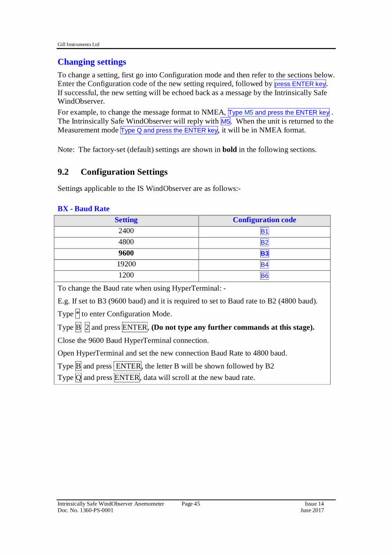
Changing settings To change a setting, first go into Configuration mode and then refer to the sections below. Enter the Configuration code of the new setting required, followed by press ENTER key. If successful, the new setting will be echoed back as a message by the Intrinsically Safe WindObserver. For example, to change the message format to NMEA, Type M5 and press the ENTER key . The Intrinsically Safe WindObserver will reply with M5. When the unit is returned to the Measurement mode Type Q and press the ENTER key, it will be in NMEA format. Note: The factory-set (default) settings are shown in bold in the following sections. 9.2 Configuration Settings Settings applicable to the IS WindObserver are as follows:-
Dx- Diagnostic and Configuration Command Each of these commands causes a response from the Intrinsically Safe WindObserver.
Item Command code Typical response
Type and serial No. D1 I03000 Software version D2 1.032
Unit configuration D3 Current configuration: B3 F1 G0000 K1 L1 M2 NA O1 P1 U1 V1 X1
Anemometer power supply voltage
D5 +07.9
Integrity check D6 See Para 10.6 Bench Tests
Fx- Data and Parity Options Setting Configuration code
8 bits, no parity, 1 stop bit F1 8 bits, even parity, 1 stop bit F2 8 bits, odd parity, 1 stop bit F3
Gx to Gxxxx - Averaging Setting Configuration code
No Averaging (Default) G0000 Enter the required averaging period in seconds as a four figure number between 0000 and 3600. If for example set for G0005 then there will be a single output once every 5 seconds based on the average of the previous five once second results.
10. Maintenance & fault-finding 10.1 Cleaning and Handling When installing the unit handle with lint free gloves and degrease the unit to reduce the build-up of deposits. If there is any build-up of deposit on the unit, it should be gently cleaned with a cloth, moistened with soft detergent. Solvents should not be used, and care should be taken to avoid scratching any surfaces. The unit must be allowed to defrost naturally after being exposed to snow or icy conditions, do NOT attempt to remove ice or snow with a tool. Always fit the protective cover supplied (see Para 5.2.5) before installation or when removing the sensor from the installation. Do NOT remove black “rubber” transducer caps. 10.2 Servicing There are no moving parts or user-serviceable parts requiring routine maintenance. Opening the unit or breaking the security seal will void the Warranty, Calibration and Certification. In the event of failure, prior to returning the unit to your authorised Gill distributor, it is recommended that: All cables and connectors are checked for continuity, bad contacts, corrosion etc. A bench test is carried out as described in Section 10.6. Contact your supplier for advice if failure persists. 10.3 Fault-finding
Symptom Solution
No output
Check DC power to the Intrinsically Safe WindObserver, cable and connections. Check comms settings of Intrinsically Safe WindObserver and host system match, including correct Com port. Check unit is in Continuous mode. Check Status code in data string (see 10.5). Check that in-line communication devices are wired correctly. NOTE: It is usual for Anemometer TX + to be connected to converter device RX +.
Corrupted output
Check comms settings of Intrinsically Safe WindObserver and host system match. Try a slower baud rate. Check cable lengths and type of cable.
One way communication Check wiring is in accordance with the manual. Failed / Incorrect Intrinsically Safe WindObserver output, data invalid flag
10.4 Safe Mode If a unit is received that will not communicate or the configuration settings are not known then Safe Mode can be used to establish communication with the IS WindObserver and change configuration settings. Initial Set Up. Connect the IS WindObserver to a PC as detailed in Para 7 using an RS422 or RS232 connection. Open a Terminal program e.g. HyperTerminal, Tera Term or use Gill Wind Software as a Terminal program. Select the required COM port. Set the Baud rate to 19200 baud (if using the Wind Terminal program it opens at 19200 baud). To Place the unit into Safe Mode. Turn off the IS WindObserver power supply. Ensure the Terminal program is set for 19200 baud, Hold down the PC keyboard * key and turn on the IS WindObserver Power Supply. The words SAFE MODE should appear on the terminal screen (press the Enter key to start a new line). If not then power down the IS WindObserver, hold the * key and power up the sensor. To Check the Unit Settings or Change settings Type D1 and press Enter, to see serial number. Type D2 and Press Enter to see Firmware version. Type D3 to see configuration settings, e.g.
SAFE MODE *************************** D1 I000157 D1 D2 1.021 D2 D3 current configuration : B3 F1 G0000 K1 L1 M2 NA O1 P1 U1 V1 X1 D3
Change settings if required referring to the previous configuration details. Type Q and press Enter to go back into measurement mode. If powering down the instrument and repowering and no change has been made to the baud rate (B command ) then open a new terminal program at the units original baud rate setting (the default setting would be 9600 Bauds to view data). 10.5 Status (error) codes
The Status code is sent as part of each wind measurement message.
Code Status Condition 00 OK Sufficient samples in average period A OK NMEA data Acceptable 01 Axis 1 failed Insufficient samples in average period on U axis 02 Axis 2 failed Insufficient samples in average period on V axis 04 Axis 1 and 2 failed Insufficient samples in average period on both axes 08 NVM error NVM checksum failed, data could be uncalibrated. 09 ROM error ROM checksum failed, data could be uncalibrated.
51 Measurement average building.
Data valid but warns that average period not reached when averaging used.
10.6 Bench Tests 10.6.1 Alignment Check. If unexplained data drop outs (code 01, 02, 04 or V code errors) are occurring then it may be possible that the IS WindObserver transducer arms have become misaligned. Mechanical Test The simplest check for Anemometer alignment is to invert the anemometer with the four transducers in contact with a flat surface. Gently hold the anemometer cylinder and then see if it is possible to feel the Anemometer rock on the transducers. If this occurs then it is likely the transducer arms are misaligned requiring return to Gill Instruments for re-alignment. 10.6.2 Connections and tests with the Mains Supply Unit Couple the Intrinsically Safe WindObserver to the power supply using a known working test cable (The 3 metre test cable connections are shown following). Anemometer Supply Voltage and Current With the PCI box powered the Supply Voltage between Terminal 26 +ve and Terminal 25 (-ve) must be between 6v dc to 12v dc. Typically 9v dc. (If the supply voltage exceeds 12 v dc damage to the Anemometer might result). The IS anemometer current through terminal 26 will typically be 14mA (maximum. 30mA).
When the IS Power Supply is powered up the +5v SAFE and +5v HAZ LED’s will be illuminated. Data Tests With the Sensor connected and outputting data to the PCI box. Examine the Main PCB and the Red RX LED at the bottom left of the PCB will be seen to flash on and off at the sensor output rate (1Hz to 4Hz). This indicates that data is being successfully output from the IS Anemometer.
With the Sensor connected and outputting data to the PCI box. Connect an RS232 or RS422 connection (see page 26) from the PCI box to a PC using a suitable converter.
Using a Terminal program (e.g. HyperTerminal/Tera Term etc.) check that the unit is correctly configured by going into Configuration mode and using D3 (See Pages 40-43).
If a HyperTerminal connection is established to change the sensor configuration then when a PC keystroke is undertaken then the PCI box Red Tx LED at the top right on the PCB will be seen to momentarily flash on and off. This indicates a good connection between the PC and the PCI box.
1. Check for normal output data, and that the Status Code is OK – 00 (or A for NMEA format).
2. If the status code is other than these, refer to Page 40 Status (error) codes. 3. Use an office fan or similar to check that the unit is sensing wind, turning the unit
to simulate changing wind direction and to check that both axes are functioning.
4. Note that this is a quick functional test. There are no calibration adjustments; the unit is designed NOT to require re-calibration within its lifetime.
Use of the Protective Head Cover for an Integrity Check An Integrity Check is designed to:
1. Identify any gross changes in the head geometry that would affect the performance.
2. Confirm the IS WindObserver zero calibration.
The Integrity Check must be used in an indoor still air environment with an ambient temperature between 17°C and 23°C. When conducting the test it is important that the protective cover is assembled on to the IS WindObserver head and not touched or moved during the test.
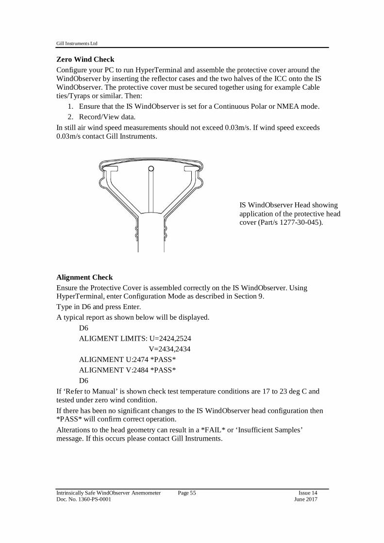
Zero Wind Check Configure your PC to run HyperTerminal and assemble the protective cover around the WindObserver by inserting the reflector cases and the two halves of the ICC onto the IS WindObserver. The protective cover must be secured together using for example Cable ties/Tyraps or similar. Then:
1. Ensure that the IS WindObserver is set for a Continuous Polar or NMEA mode. 2. Record/View data.
In still air wind speed measurements should not exceed 0.03m/s. If wind speed exceeds 0.03m/s contact Gill Instruments.
Alignment Check Ensure the Protective Cover is assembled correctly on the IS WindObserver. Using HyperTerminal, enter Configuration Mode as described in Section 9. Type in D6 and press Enter. A typical report as shown below will be displayed. D6 ALIGMENT LIMITS: U=2424,2524 V=2434,2434 ALIGNMENT U:2474 *PASS* ALIGNMENT V:2484 *PASS* D6 If ‘Refer to Manual’ is shown check test temperature conditions are 17 to 23 deg C and tested under zero wind condition. If there has been no significant changes to the IS WindObserver head configuration then *PASS* will confirm correct operation. Alterations to the head geometry can result in a *FAIL* or ‘Insufficient Samples’ message. If this occurs please contact Gill Instruments.
IS WindObserver Head showing application of the protective head cover (Part/s 1277-30-045).
10.6.3 Connections and tests with the Low Voltage Supply Unit Couple the Intrinsically Safe WindObserver to the power supply unit using a known working test cable (The 3 metre test cable connections to terminal block J5 are shown following).
IS WindObserver 3 Metre Test Cable Connection Table to LVPCI Box J5. LVPCI Box J5 Connector Test Cable Wire Colour Description
Terminal 2 Cable Screen Screen Terminal 3 Green (Green and Black Pair) RS422 Data +ve to Anemometer (Config only) Terminal 4 Black (Green and Black Pair) RS422 Data –ve to Anemometer (Config only) Terminal 5 Black (White and Black Pair) RS422 Transmit -ve data from Anemometer Terminal 6 White (White and Black Pair) RS422 Transmit +ve data from Anemometer Terminal 7 Black (Red and Black Pair) Power Supply –ve Terminal 8 Red (Red and Black Pair) Power Supply +ve
Connect a standard RS232, 9 pin D Type to D Type connector lead to the LVPCI Box socket J3. Connect this lead to a PC via its Serial Com port or via an RS232 to USB converter. PC Serial COM Port Connection to LVPCI Box J3.
LVPCI Box J3 PC, 9 Way D Type Serial COM Port 2 2 3 3 5 5
Anemometer Supply Voltage and Current With the LVPCI box powered, the Supply Voltage between J5 Terminal 8 +ve and Terminal 7 (-ve) must be between 6v dc to 12v dc. Typically 9v dc. (If the supply voltage exceeds 12 v dc damage to the Anemometer might result). The IS anemometer current through J5, Terminal 8 will typically be 14mA (maximum. 30mA). When the IS Power Supply is powered up the +5v NON HAZ and +5v HAZ LED’s will be illuminated. Data Tests With the Sensor connected and outputting data to the PCI box. Examine the Main PCB and the Red RX LED will be seen to flash on and off at the sensor output rate (1Hz to 4Hz). This indicates that data is being successfully output from the IS Anemometer.
With the Sensor connected and outputting data to the PCI box.
1. Check that the unit is correctly configured by going into Configuration mode and using D3 , see Page 43.
If a HyperTerminal connection is established to change the sensor configuration then when a PC keystroke is undertaken then the PCI box Red Tx LED on the PCB will be seen to momentarily flash on and off. This indicates a good connection between the PC and the PCI box.
2. Check for normal output data, and that the Status Code is OK – 00 (or A for NMEA format).
3. If the status code is other than these, refer to Page 40 Status (error) codes. 4. Use an office fan or similar to check that the unit is sensing wind, turning the unit
to simulate changing wind direction and to check that both axes are functioning.
5. Note that this is a quick functional test. There are no calibration adjustments; the unit is designed NOT to require re-calibration within its lifetime.
Use of the Protective Head Cover for an Integrity Check An Integrity Check is designed to:
3. Identify any gross changes in the head geometry that would affect the performance.
4. Confirm the IS WindObserver zero calibration.
The Integrity Check must be used in an indoor still air environment with an ambient temperature between 17°C and 23°C. When conducting the test it is important that the protective cover is assembled on to the IS WindObserver head and not touched or moved during the test.
Zero Wind Check Configure your PC to run HyperTerminal and assemble the protective cover around the WindObserver by inserting the reflector cases and the two halves of the ICC onto the IS WindObserver. The protective cover must be secured together using for example Cable ties/Tyraps or similar. Then:
3. Ensure that the IS WindObserver is set for a Continuous Polar or NMEA mode. 4. Record/View data.
In still air wind speed measurements should not exceed 0.03m/s. If wind speed exceeds 0.03m/s contact Gill Instruments.
Alignment Check Ensure the Protective Cover is assembled correctly on the IS WindObserver. Using HyperTerminal, enter Configuration Mode as described in Section 9. Type in D6 and press Enter. A typical report as shown below will be displayed. D6 ALIGMENT LIMITS: U=2424,2524 V=2434,2434 ALIGNMENT U:2474 *PASS* ALIGNMENT V:2484 *PASS* D6 If ‘Refer to Manual’ is shown check test temperature conditions are 17 to 23 deg C and tested under zero wind condition. If there has been no significant changes to the IS WindObserver head configuration then *PASS* will confirm correct operation. Alterations to the head geometry can result in a *FAIL* or ‘Insufficient Samples’ message. If this occurs please contact Gill Instruments. 10.7 Returning Units If the unit has to be returned, it should be carefully packed in the original packaging and returned to your authorised Gill distributor, with a full description of the fault condition.
IS WindObserver Head showing application of the protective head cover (Part/s 1277-30-045).
APPENDIX 1 SUMMARY OF ABBREVIATIONS USED IN THIS MANUAL AC Alternating Current ANEM Anemometer ASCII American Standard Code for Information Interchange CR Carriage Return CSV Comma Separated Variable CSA Cross Sectional Area CTS Clear To Send DC Direct Current DCD Data Carrier Detect DDD Direction parameter DEG DEGrees DSR Data Set Ready DTR Data Terminal Ready EEPROM Electrically Erasable Programmable Read Only Memory EMC Electro-Magnetic Compatibility ETX End of string character FPM Feet Per Minute GND GrouND HEX Hexadecimal HZ Hertz IP65 Ingress Protection Classification I.S Intrinsic Safety K Kilometres per hour Knots Nautical Measurement of speed KM KiloMetre KPH KiloMetres Per Hour LF Line Feed M3 Operating Mode 3 M4 Operating Mode 4 mA MilliAmperes MPH Miles Per Hour mm MilliMetres ms MilliSecond m/s Metres per Second PC IBM PC or compatible computer PCI Power and Communications Interface POR Power On Reset RH Relative Humidity RMS Root Mean Squared RS232 Communications standard RS422 Communications standard RTS Request To Send RI Ring Initiate RX Receive
SEC SECond RAM Static Random Access Memory STX Start of string character S/W SoftWare TX Transmit UV Cartesian Co-ordinate System V Volts V+ positive Voltage V- negative Voltage VA VoltAmperes
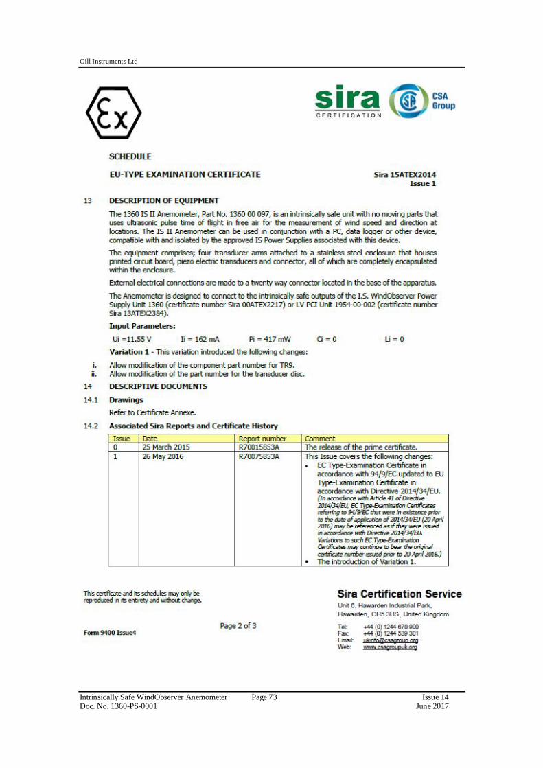
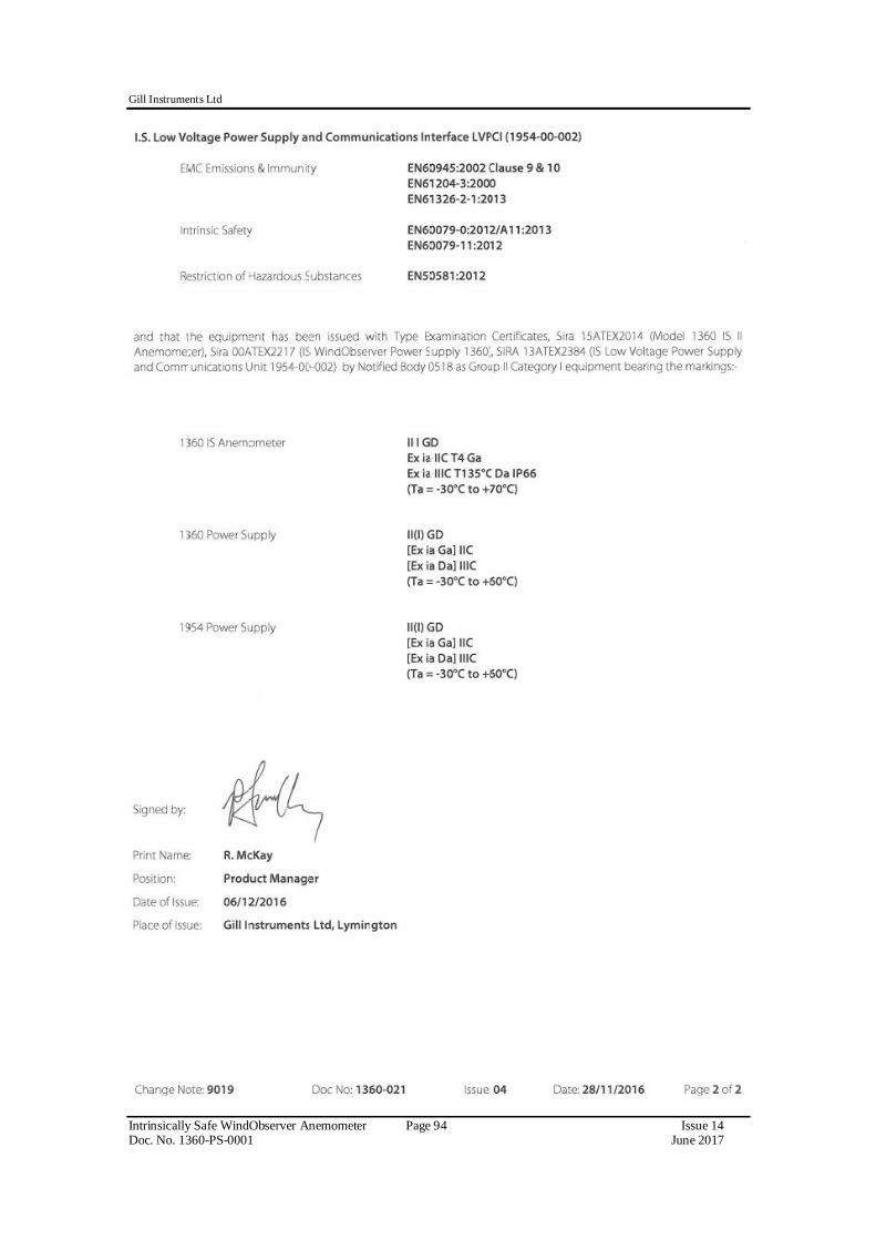
1. Certificate Number: Sira 00ATEX2217 Issue 11 for the IS WindObserver Power Supply Unit 1360.
2. Certificate Number: Sira 15ATEX2014 Issue 1 for the model 1360 IS II Anemometer.
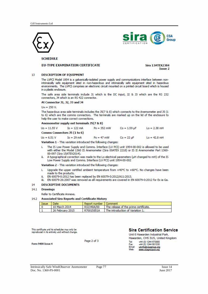
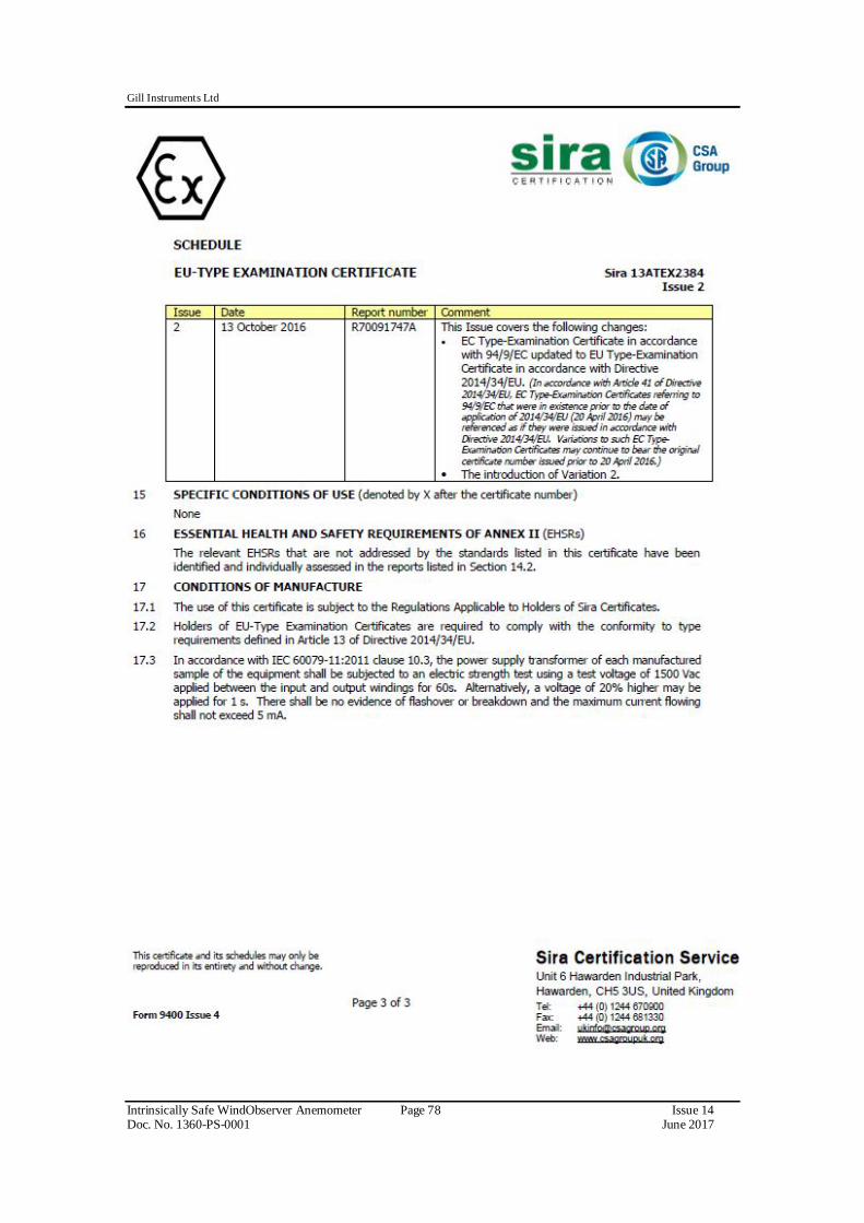
3. Certificate Number: Sira 13ATEX2384 Issue 2 for the IS Low Voltage Power Supply and Communications Unit 1954-00-002.
SIRA IECEx CERTIFICATION
4. Certificate Number: Sira IECEx SIR 13.0156 Issue 4 for the IS WindObserver Power Supply Unit 1360.
5. Certificate Number: Sira IECEx SIR 15.0013 Issue 1 for the model 1360 IS II Anemometer.
6. Certificate Number: Sira IECEx SIR 13.0159 Issue 2 for the IS Low Voltage Power Supply and Communications Interface 1954-00-002. Copies of the above SIRA IECEx certificates may be downloaded from:- I.S. WindObserver Power Supply Unit 1360 http://iecex.iec.ch/iecex/iecexweb.nsf/CoCHistory/IECEx%20SIR%2013.01564 I.S. II WindObserver Anemometer http://iecex.iec.ch/iecex/iecexweb.nsf/CoCHistory/IECEx%20SIR%2015.00131 IS Low Voltage Power Supply and Communications Interface 1954-00-002 http://iecex.iec.ch/iecex/iecexweb.nsf/CoCHistory/IECEx%20SIR%2013.01592