User Manual The colour and the appearance may differ depending on the product, and the specifications are subject to change without prior notice to improve the performance. Recommended hours of use per day for the DBJ, QBH, QHH models is less than 16 hours. If the product is used for longer than 16 hours a day, the warranty may be void. DBJ (DB43J DB49J) QBH (QB65H QB75H) QHH (QH55H QH65H) QMH (QM49H QM55H QM65H)
Transcript
User Manual
The colour and the appearance may differ depending on the product, and the specifications are subject to change without prior notice to improve the performance.Recommended hours of use per day for the DBJ, QBH, QHH models is less than 16 hours.If the product is used for longer than 16 hours a day, the warranty may be void.
Safety Precautions 7Cleaning 7Storage 8Electricity and Safety 8Installation 9Operation 11
Preparations
Checking the Components 14Components 14
Parts 15Control Panel 15Reverse Side 19Anti-theft Lock 22Remote Control 23
Before Installing the Product (Installation Guide) 25Tilting Angle and Rotation 25Ventilation 25
Installing the Wall Mount 27Preparing before installing Wall-Mount 28Installing the Wall Mount 28Wall Mount Kit Specifications (VESA) 29
Remote Control (RS232C) 30
Cable Connection 30Connection 33Control Codes 34
Connecting and Using a Source Device
Before Connecting 42Pre-connection Checkpoints 42
Connecting to a PC 42Connection Using an HDMI Cable 42Connection Using an DP Cable 43Connection using a DVI cable (Digital type) 43Connection Using an HDMI-DVI Cable 44
Connecting an External Monitor 45
Connecting to a Video Device 46Connection Using an HDMI-DVI Cable 46Connection Using an HDMI Cable 47
Connecting to an Audio System 47
Power cord connection guide 48
Attaching the Network box (Sold separately) 49
Connecting the Network box (Sold separately) 50MagicInfo 50
Advanced Settings 85Contrast Enhancer 85Black Tone 85Flesh Tone 85RGB Only Mode 85Colour Space Settings 86HDMI UHD Color 86Motion Lighting 86HDR+ Mode 86
Picture Options 87Colour Tone 87Digital Clean View 87HDMI Black Level 88Film Mode 88Auto Motion Plus Settings 89Local Dimming 89Dynamic Backlight 90
Picture Size Settings 91Picture Size 91Fit to screen 91Zoom and Position 91
Reset Picture 92
OnScreen Display
Display Orientation 93Onscreen Menu Orientation 93Source Content Orientation 93Aspect Ratio 93
Screen Protection 94Auto Protection Time 94Screen Burn Protection 94
Message Display 97Source Info 97No Signal Message 97MDC Message 97Download Status Message 97
Language 98
Reset OnScreen Display 98
Sound Adjustment
Sound Mode 99
Balance 100
Equaliser 100
HDMI Sound 100
Sound on Video Call 100
Sound Output 101
Auto Volume 101
3
Table of contents
Reset Sound 101
Network
Network Status 102
Open Network Settings 102Network Type 102Network Settings (Wired) 103Network Settings (Wireless) 105Use WPS 107
Server Network Settings 108Connect to server 108MagicInfo Mode 108Server Access 108FTP Mode 108Proxy server 108
Device Name 108
System
Accessibility 109High Contrast 109Enlarge 109
Start Setup 110
Touch Control 110Touch Control 110Admin Menu Lock 110
Security 120Safety Lock On 120Button Lock 120USB Auto Play Lock 120Mobile Connection Lock 121Remote Management 121
General 122Smart Security 122Anynet+ (HDMI-CEC) 122HDMI Hot Plug 124Custom Logo 124Game Mode 125Irregular Video Wall 125
Reset System 125
Support
Software Update 126Update Now 126Auto update 126
Contact Samsung 126
Reset All 126
4
Table of contents
Troubleshooting Guide
Requirements Before Contacting Samsung Customer Service Centre 127Testing the Product 127Checking the Resolution and Frequency 127Check the followings. 128
Q & A 134
Specifications
General 135
Preset Timing Modes 137
Appendix
Responsibility for the Pay Service (Cost to Customers) 142Not a product defect 142A Product damage caused by customer's fault 142Others 142
Prevention of Afterimage Burn-in 143What is afterimage burn-in? 143Recommended prevention practices 143
Licence 144
Terminology 145
5
6
Before Using the Product
CopyrightThe contents of this manual are subject to change without notice to improve quality.
Samsung Electronics owns the copyright for this manual.
Use or reproduction of this manual in parts or entirety without the authorization of Samsung Electronics is prohibited.
Microsoft, Windows are registered trademarks of Microsoft Corporation.
VESA, DPM and DDC are registered trademarks of the Video Electronics Standards Association.
Ownership of all other trademarks is attributed to their due owner.
• An administration fee may be charged if either – (a) an engineer is called out at your request and there is no defect in the product
(i.e. where you have failed to read this user manual). – (b) you bring the unit to a repair centre and there is no defect in the product
(i.e. where you have failed to read this user manual).
• The amount of such administration charge will be advised to you before any work or home visit is carried out.
Chapter 01
7
Safety Precautions
WarningA serious or fatal injury may result if instructions are not followed.
CautionPersonal injury or damage to properties may result if instructions are not followed.
Activities marked by this symbol are prohibited.
Instructions marked by this symbol must be followed.
Cleaning ― Exercise care when cleaning as the panel and exterior of advanced LCDs are easily scratched. ― Take the following steps when cleaning. ― The following images are for reference only. Real-life situations may differ from what is shown in the images.
1 Power off the product and computer.
2 Disconnect the power cord from the product.
― Hold the power cable by the plug and do not touch the cable with wet hands. Otherwise, an electric shock may result.
!
3 Wipe the product with a clean, soft and dry cloth.
• Do not use detergents that contain alcohol, solvent or surface-active agents.
• Do not spray water or detergent directly on the product.
4 Wet a soft and dry cloth in water and wring thoroughly to clean
the exterior of the product.
5 Connect the power cord to the product when cleaning is
finished.
6 Power on the product and computer.
8
StorageDue to the characteristics of high-glossy products, using a UV humidifier nearby may create white-coloured stains on the product.
― Contact Customer Service Centre if the inside of the product needs cleaning (service fee will be charged).
Electricity and Safety ― The following images are for reference only. Real-life situations may differ from what is shown in the images.
Warning
Do not use a damaged power cord or plug, or a loose power socket.
• An electric shock or fire may result.
Do not use multiple products with a single power socket.
• Overheated power sockets may cause a fire.
Do not touch the power plug with wet hands. Otherwise, an electric shock may result.
!
Insert the power plug all the way in so it is not loose.
• An unsecure connection may cause a fire.
!
Connect the power plug to a grounded power socket (type 1 insulated devices only).
• An electric shock or injury may result.
Do not bend or pull the power cord with force. Be careful not to leave the power cord under a heavy object.
• Damage to the cord may result in a fire or electric shock.
Do not place the power cord or product near heat sources.
• A fire or electric shock may result.
!
Clean any dust around the pins of the power plug or the power socket with a dry cloth.
• A fire may result.
9
Caution
Do not disconnect the power cord while the product is being used.
• The product may become damaged by an electric shock.
!
Only use the power cord provided with your product by Samsung. Do not use the power cord with other products.
• A fire or electric shock may result.
!
Keep the power socket where the power cord is connected unobstructed.
• The power cord must be disconnected to cut off power to the product when an issue occurs.
• Note that the product is not completely powered down by using only the power button on the remote.
!
Hold the plug when disconnecting the power cord from the power socket.
• An electric shock or fire may result.
Installation
Warning
DO NOT PLACE CANDLES, INSECT REPELLANTS OR CIGARETTES ON TOP OF THE PRODUCT. DO NOT INSTALL THE PRODUCT NEAR HEAT SOURCES.
• A fire may result.
!
Have a technician install the wall-mount hanger.
• Installation by an unqualified person can result in an injury.
• Only use approved cabinets.
Do not install the product in poorly ventilated spaces such as a bookcase or closet.
• An increased internal temperature may cause a fire.
!
Install the product at least 10 cm away from the wall to allow ventilation.
• An increased internal temperature may cause a fire.
!
Keep the plastic packaging out of the reach of children.
• Children may suffocate.
10
Do not install the product on an unstable or vibrating surface (insecure shelf, sloped surface, etc.)
• The product may fall and become damaged and/or cause an injury.
• Using the product in an area with excess vibration may damage the product or cause a fire.
!
Do not install the product in a vehicle or a place exposed to dust, moisture (water drips, etc.), oil, or smoke.
• A fire or electric shock may result.
Do not expose the product to direct sunlight, heat, or a hot object such as a stove.
• The product lifespan may be reduced or a fire may result.
Do not install the product within the reach of young children.
• The product may fall and injure children.
• As the front is heavy, install the product on a flat and stable surface.
Edible oil, such as soybean oil, can damage or deform the product. Do not install the product in a kitchen or near a kitchen counter.
Caution
!
Do not drop the product while moving.
• Product failure or personal injury may result.
Do not set down the product on its front.
• The screen may become damaged.
When installing the product on a cabinet or shelf, make sure that the bottom edge of the front of the product is not protruding.
• The product may fall and become damaged and/or cause an injury.
• Install the product only on cabinets or shelves of the right size.
!
Set down the product gently.
• Product failure or personal injury may result.
SAMSUNG
!
Installing the product in an unusual place (a place exposed to a lot of fine dust, chemical substances, extreme temperatures or a significant presence of moisture, or a place where the product will operate continuously for an extended period of time) may seriously affect its performance.
• Be sure to consult Samsung Customer Service Centre if you want to install the product at such a place.
11
Operation
Warning
There is a high voltage inside the product. Never disassemble, repair or modify the product yourself.
• A fire or electric shock may result.
• Contact Samsung Customer Service Centre for repairs.
!
Before moving the product, turn off the power switch and disconnect the power cable and all other connected cables.
• Damage to the cord may result in a fire or electric shock.
!
If the product generates abnormal sounds, a burning smell or smoke, disconnect the power cord immediately and contact Samsung Customer Service Centre.
• An electric shock or fire may result.
Do not let children hang from the product or climb on top of it.
• Children may become injured or seriously harmed.
If the product is dropped or the outer case is damaged, turn off the power switch and disconnect the power cord. Then contact Samsung Customer Service Centre.
• Continued use can result in a fire or electric shock.
Do not leave heavy objects or items that children like (toys, sweets, etc.) on top of the product.
• The product or heavy objects may fall as children try to reach for the toys or sweets resulting in a serious injury.
!
During a lightning or thunderstorm, power off the product and remove the power cable.
• A fire or electric shock may result.
!
Do not drop objects on the product or apply impact.
• A fire or electric shock may result.
Do not move the product by pulling the power cord or any cable.
• Product failure, an electric shock or fire may result from a damaged cable.
!GAS
If a gas leakage is found, do not touch the product or power plug. Also, ventilate the area immediately.
• Sparks can cause an explosion or fire.
Do not lift or move the product by pulling the power cord or any cable.
• Product failure, an electric shock or fire may result from a damaged cable.
12
!
Do not use or keep combustible spray or an inflammable substance near the product.
• An explosion or fire may result.
Ensure the vents are not blocked by tablecloths or curtains.
• An increased internal temperature may cause a fire.
100
Do not insert metallic objects (chopsticks, coins, hairpins, etc) or objects that burn easily (paper, matches, etc) into the product (via the vent or input/output ports, etc).
• Be sure to power off the product and disconnect the power cord when water or other foreign substances have entered the product. Then contact Samsung Customer Service Centre.
• Product failure, an electric shock or fire may result.
Do not place objects containing liquid (vases, pots, bottles, etc) or metallic objects on top of the product.
• Be sure to power off the product and disconnect the power cord when water or other foreign substances have entered the product. Then contact Samsung Customer Service Centre.
• Product failure, an electric shock or fire may result.
Caution
!
Leaving the screen fixed on a stationary image for an extended period of time may cause afterimage burn-in or defective pixels.
• Activate power-saving mode or a moving-picture screen saver if you will not be using the product for an extended period of time.
-_-
!
Disconnect the power cord from the power socket if you do not plan on using the product for an extended period of time (vacation, etc).
• Dust accumulation combined with heat can cause a fire, electric shock or electric leakage.
!
Use the product at the recommended resolution and frequency.
• Your eyesight may deteriorate.
Do not hold the product upside-down or move it by holding the stand.
• The product may fall and become damaged or cause an injury.
!
Looking at the screen too close for an extended period of time can deteriorate your eyesight.
Do not use humidifiers or stoves around the product.
• A fire or electric shock may result.
13
!
Rest your eyes for more than 5 minutes for every 1 hour of product use.
• Eye fatigue will be relieved.
Do not touch the screen when the product has been turned on for an extended period of time as it will become hot.
!
Store small accessories out of the reach of children.
!
Exercise caution when adjusting the product angle or stand height.
• Your hand or finger may get stuck and injured.
• Tilting the product at an excessive angle may cause the product to fall and an injury may result.
Do not place heavy objects on the product.
• Product failure or personal injury may result.
When using headphones or earphones, do not turn the volume too high.
• Having the sound too loud may damage your hearing.
Be careful that children do not place the battery in their mouths when removed from the remote control. Place the battery in a location that children or infants cannot reach.
• If children have had the battery in their mouths, consult your doctor immediately.
!
When replacing the battery, insert it with the right polarity (+, -).
• Otherwise, the battery may become damaged or it may cause fire, personal injury or damage due to leakage of the internal liquid.
Use only the specified standardised batteries, and do not use a new battery and a used battery at the same time.
• Otherwise, the batteries may be damaged or cause fire, personal injury or damage due to a leakage of the internal liquid.
!
The batteries (and rechargeable batteries) are not ordinary refuse and must be returned for recycling purposes. The customer is responsible for returning the used or rechargeable batteries for recycling.
• The customer can return used or rechargeable batteries to a nearby public recycling centre or to a store selling the same type of the battery or rechargeable battery.
14
– Contact the vendor where you purchased the product if any components are missing.
– The appearance of the components may differ from the images shown.
– A stand is not provided with the product. To install a stand, you can purchase one separately.
– The RS232C adapter can be used to connect to another monitor using the D-SUB (9-pin) type RS232C cable.
Checking the Components
Components
Quick Setup GuideWarranty card
(Not available in some locations)Regulatory guide Power cord
Batteries
(Not available in some locations)Remote Control RS232C(IN) adapter
Cover Terminal
(Supported models: QHH)
Wall Mount Adapter (4 EA)
(Supported models: QHH)
HOLDER-CABLE (3 EA)
(Supported models: QBH, QH65H)
PreparationsChapter 02
15
Parts
Control PanelDBJ QHH
QB65H / QMH
Speaker Speaker
Speaker
Remote sensor & Panel Key
Spacer logo
Remote sensor & Panel Key
QB65H / QHH / QMH
― The colour and shape of parts may differ from what is shown. Specifications are subject to change without notice to improve quality.
Parts Description
Spacer logoDo not pull on the spacer logo using force. The logo may tear or break off.
― Supported models: QB65H, QMH
Remote sensor
Press a button on the remote control pointing at the bottom of the product face to perform the function. The remote control sensor is located on the bottom of the product.
― Using other display devices in the same space as the remote control of this product can cause the other display devices to be inadvertently controlled.
To use remote/eco sensor, make sure the sliding panel key is protruding from the bottom of the product.
― Supported models: QB65H, QHH, QMH
Panel KeyTo use the panel key, make sure the sliding panel key is not protruding from the bottom of the product.
― Supported models: QB65H, QHH, QMH
Use the remote control within 7 m to 10 m from the sensor on the product at an angle of 30° from the left and right. ― Store used batteries out of reach of children and recycle. ― Do not use a new and used battery together. Replace both batteries at the same time. ― Remove batteries when the remote control is not to be used for an extended period of time.
16
― The panel key is located on the bottom right front of the product. ― If you press the P button on the panel key when the product is turned on, the control menu will be displayed.
Control menu
Power off Source
Press: Move Press & Hold: Select
Buttons Description
Power off
Power off the product.
With the control menu screen displayed, briefly press the panel key to move the cursor to Power off , and then press and hold the panel key to turn off the product.
Source
Select the connected input source.
With the control menu screen displayed, briefly press the panel key to move the cursor to Source , and then press and hold the panel key to display the input source screen.
With the input source screen displayed, press and hold the panel key to switch to the desired input source.
― The panel key can only be used for Power off and Source. ― To exit from the control menu screen, wait for 3 seconds or more without pressing the panel key.
17
Control Panel
Speaker
Panel Key
QB75H
Spacer logo
Remote sensor
― The colour and shape of parts may differ from what is shown. Specifications are subject to change without notice to improve quality.
Parts Description
Power on the product.
If you press the button when the product is turned on, the control menu will be displayed.
― To exit the OSD menu, press and hold the panel key for at least one second.
Move to the upper or lower menu. You can also adjust the value of an option.
Move to the left or right menu. ― You can adjust the volume by moving the panel key left or right when the control menu is not displayed.
Spacer logo Do not pull on the spacer logo using force. The logo may tear or break off.
Remote sensor
Press a button on the remote control pointing at the bottom of the product face to perform the function. The remote control sensor is located on the bottom of the product.
― Using other display devices in the same space as the remote control of this product can cause the other display devices to be inadvertently controlled.
Use the remote control within 7 m to 10 m from the sensor on the product at an angle of 30° from the left and right. ― Store used batteries out of reach of children and recycle. ― Do not use a new and used battery together. Replace both batteries at the same time. ― Remove batteries when the remote control is not to be used for an extended period of time.
18
― If you press the button on the panel key when the product is turned on, the control menu will be displayed.
Control menu
Home
Return
Power off
Settings Source
Buttons Description
HomeDisplay the Player menu.
Move the panel key up to select Home in the control menu.
Settings
Display the OSD menu.
Move the panel key left to select Settings in the control menu. The OSD control screen will appear. Move the panel key right to select the desired menu. You can select a sub-menu item by moving the panel key up, down, left, or right. To change settings, select the desired menu and press the panel key.
Power offPower off the product.
Move the panel key down to select Power off in the control menu. Next, press the panel key.
Source
Select the connected input source.
Move the panel key right to select Source in the control menu. When the list of input sources is displayed, move the panel key left or right to select the desired input source. Next, press the panel key.
Return Exit the control menu.
19
Reverse Side ― The colour and shape of parts may differ from what is shown. Specifications are subject to change without notice to improve quality.
QHH
Port Description
RS232C OUT Connects to MDC using an RS232C adapter.
RS232C IN
RJ45 Connects to MDC using a LAN cable. (10/100 Mbps) ― Use Cat7(*STP Type) cable for the connection.*Shielded Twist Pair.
DP IN Connects to a PC using a DP cable.
HDMI 1 (ARC) Connects to a source device using a HDMI cable or HDMI-DVI cable.
HDMI 2
USB ¨(5V 0.5A) Connect to a USB memory device. ― The USB ports on the product accept a maximum constant current of 0.5A. If the maximum value is exceeded, USB ports may not work.
USB ¨(5V 1A) Connect to a USB memory device. ― The USB ports on the product accept a maximum constant current of 1.0A. If the maximum value is exceeded, USB ports may not work.
20
Reverse Side ― The colour and shape of parts may differ from what is shown. Specifications are subject to change without notice to improve quality.
QMHQBH
Port Description
USB 1 ¨(1.0A) Connect to a USB memory device. ― The USB ports on the product accept a maximum constant current of 1.0A. If the maximum value is exceeded, USB ports may not work.
RJ45 Connects to MDC using a LAN cable. (10/100 Mbps) ― Use Cat7(*STP Type) cable for the connection.*Shielded Twist Pair.
RS232C IN Connects to MDC using an RS232C adapter.
DVI/MAGICINFO IN DVI: Connects to a source device using a DVI cable or HDMI-DVI cable.MAGICINFO IN: To use MagicInfo, make sure to connect the DP-DVI cable.
HDMI IN 1 (ARC) Connects to a source device using a HDMI cable or HDMI-DVI cable.
HDMI IN 2
HDMI IN 2 (DAISY CHAIN IN)
DP IN Connects to a PC using a DP cable.
DP IN (DAISY CHAIN IN)
HDMI OUT (DAISY CHAIN OUT) Connects to another product using a HDMI cable.
USB 2(0.5A) Connect to a USB memory device. ― The USB ports on the product accept a maximum constant current of 0.5A. If the maximum value is exceeded, USB ports may not work.
DVI/HDMI/AUDIO IN Receives sound from a PC via an audio cable.
AUDIO OUT Connects to the audio of a source device.
IR IN Supplies power to the external sensor board or receives the light sensor signal.
RS232C OUT Connects to MDC using an RS232C adapter.
21
Reverse Side ― The colour and shape of parts may differ from what is shown. Specifications are subject to change without notice to improve quality.
DBJ
Port Description
USB 1 ¨(1.0A) Connect to a USB memory device. ― The USB ports on the product accept a maximum constant current of 1.0A. If the maximum value is exceeded, USB ports may not work.
HDMI IN 1 (ARC) Connects to a source device using a HDMI cable or HDMI-DVI cable.
HDMI IN 2
DVI/MAGICINFO IN DVI: Connects to a source device using a DVI cable or HDMI-DVI cable.MAGICINFO IN: To use MagicInfo, make sure to connect the DP-DVI cable.
RS232C IN Connects to MDC using an RS232C adapter.
RS232C OUT
RJ45 Connects to MDC using a LAN cable. (10/100 Mbps) ― Use Cat7(*STP Type) cable for the connection.*Shielded Twist Pair.
DVI/HDMI/AUDIO IN Receives sound from a PC via an audio cable.
AUDIO OUT Connects to the audio of a source device.
22
Anti-theft Lock ― An anti-theft lock allows you to use the product securely even in public places. ― The locking device shape and locking method depend on the manufacturer. Refer to the user guide provided with your anti-theft locking device for details.
― The following images are for reference only. Real-life situations may differ from what is shown in the images.
To lock an anti-theft locking device:QBH / QHH / QMH DBJDBJ
1 Fix the cable of your anti-theft locking device to a heavy object such as a desk.
2 Put one end of the cable through the loop on the other end.
3 Insert the locking device into the anti-theft lock slot at the back of the product.
4 Lock the locking device.
– An anti-theft locking device can be purchased separately. – Refer to the user guide provided with your anti-theft locking device for details. – Anti-theft locking devices can be purchased at electronics retailers or online.
23
HOMEMENU
POWEROFF
VOL CH
MagicInfoPlayer I
.QZ
1ABC
2DEF
3GHI
4JKL
5MNO
6
SYMBOL
0
PRS
7TUV
8WXY
9
MUTE
DEL-/--
SOURCE
CH LIST
Power off the product.
Number buttons
Enter the password in the OSD menu.
Mute the sound.
Unmuting the sound: Press MUTE again or press the volume control(+ VOL -) button.
Player Launch Button.
Display or hide the onscreen display menu, or return to the previous menu.
Power on the product.
Adjust the volume.
Change the input source.
DBJ / QBH / QMH: Use this hotkey to directly access MagicInfo. This hotkey is available when a network box is connected.
– Remote control button functions may differ for different products.
Remote Control ― Using other display devices in the same space as the remote control of this product can cause the other display devices to be inadvertently controlled. ― A button without a description in the image below is not supported on the product.
24
TOOLS INFO
SET UNSET LOCK
PC
ADVI
BHDMI
CDP
D
EXITRETURN
IR control
Display information about the current input source.
Move to the upper, lower, left or right menu, or adjust an option's setting.
Confirm a menu selection.
Exit the current menu.
DBJ: Manually select a connected input source from DVI, HDMI 1 or HDMI 2.
QHH: Manually select a connected input source from HDMI 1, HDMI 2 or DisplayPort.
QBH / QMH: Manually select a connected input source from DVI, HDMI 1, HDMI 2 or DisplayPort.
Quickly select frequently used functions.
Return to the previous menu.
It sets safe lock function.If multiple products are connected through the
Video Wall feature, press the SET button and enter a product ID using the number buttons.
Control the product using the remote control.
Cancel a value that has been set using the SET button and control all connected products using
the remote control.
– Remote control button functions may differ for different products.
– Remove batteries when the remote control is not to be used for an extended period of time.
To place batteries in the remote control
25
Before Installing the Product (Installation Guide)
15°
To prevent injury, this apparatus must be securely attached to the floor/wall in accordance with the installation instructions.
• Ensure that an authorised installation company installs the wall mount.
• Otherwise, it may fall and cause personal injury.
• Make sure to install the specified wall mount.
Tilting Angle and Rotation ― Contact Samsung Customer Service Centre for further details.
• The product can be tilted at a maximum angle of 15° from a perpendicular wall surface.
• To use the product vertically (portrait), turn it clockwise so that the LED is pointing down.
A
B
Ventilation ― Contact Samsung Customer Service Centre for further details.
Installation on a Perpendicular WallA Minimum 40 mm
B Ambient temperature: Under 35°C ― When installing the product on a perpendicular wall, allow at least 40 mm of space between the product and wall surface for ventilation and ensure that the ambient A temperature is kept below 35°C.
26
B
C
E
A
DD
Installation on an Indented WallA Minimum 40 mm
B Minimum 70 mm
C Minimum 50 mm
D Minimum 50 mm
E Ambient temperature: Under 35°C ― When installing the product on an indented wall, allow at least the space specified above between the product and wall for ventilation and ensure that the ambient temperature is kept below 35°C.
27
Installing the Wall Mount ― The cover is easily removable by hand. Remove the cover when you install the wall mount. Do not remove the cover when you do not install the wall mount. ― Removing the cover is necessary only when installing the WMN-M11E (No gap wall mount). ― Supported models: QHH
1 2 3
28
To install a wall-mount from another manufacturer, use the Wall Mount Adapter(1). ― Supported models: QHH
Installing the Wall MountThe wall mount kit (sold separately) allows you to mount the product on the wall.
For detailed information on installing the wall mount, see the instructions provided with the wall mount.
We recommend you contact a technician for assistance when installing the wall mount bracket.
Samsung Electronics is not responsible for any damage to the product or injury to yourself or others if you elect to install the wall mount on your own.
Preparing before installing Wall-Mount
1
29
― Install your wall mount on a solid wall perpendicular to the floor. Before attaching the wall mount to surfaces other than plaster board, please contact your nearest dealer for additional information.If you install the product on a slanted wall, it may fall and result in severe personal injury.
• Samsung wall mount kits contain a detailed installation manual and all parts necessary for assembly are provided.
• Do not use screws that are longer than the standard length or do not comply with the VESA standard screw specifications. Screws that are too long may cause damage to the inside of the product.
• For wall mounts that do not comply with the VESA standard screw specifications, the length of the screws may differ depending on the wall mount specifications.
• Do not fasten the screws too firmly. This may damage the product or cause the product to fall, leading to personal injury. Samsung is not liable for these kinds of accidents.
• Samsung is not liable for product damage or personal injury when a non-VESA or non-specified wall mount is used or the consumer fails to follow the product installation instructions.
• Do not mount the product at more than a 15 degree tilt.
• Always have two people mount the product on a wall.
• Standard dimensions for wall mount kits are shown in the table below.
Model name VESA screw hole specs (A * B) in millimetres (inches)
Standard Screw Quantity
DBJ 200 × 200 (7.9 × 7.9)M8 4
QBH / QHH / QMH 400 × 400 (15.7 × 15.7)
― Do not install your Wall Mount Kit while your product is turned on. It may result in personal injury due to electric shock.
― If you want to use a wall mount, make sure that it allows you to remove the product from it without using any additional tool. (Supported models: DBJ)
Wall Mount Kit Specifications (VESA)
30
Remote Control (RS232C)
Cable Connection
RS232C Cable
Interface RS232C (9 pins)
Pin TxD (No.2), RxD (No.3), GND (No.5)
Bit rate 9600 bps
Data bits 8 bit
Parity None
Stop bit 1 bit
Flow control None
Maximum length 15 m (only shielded type)
• Pin assignment
1 2 3 4 5
6 7 8 9
5 4 3 2 1
9 8 7 6
<Male type> <Female type>
Pin Signal
1 Detect data carrier
2 Received data
3 Transmitted data
4 Prepare data terminal
5 Signal ground
6 Prepare data set
7 Send request
8 Clear to send
9 Ring indicator
31
• RS232C cableConnector: 9-Pin D-Sub to Stereo Cable
5
16
9
-P2-
123
-P1-
-P1- -P1- -P2- -P2-
Male type Rx
Tx
Gnd
3
2
5
----------
----------
----------
1
2
3
Tx
Rx
Gnd
STEREO
PLUG
(3.5ø)
LAN Cable • Pin assignment
1 2 3 4 5 6 7 8
Pin No Standard Colour Signal
1 White and orange TX+
2 Orange TX-
3 White and green RX+
4 Blue NC
5 White and blue NC
6 Green RX-
7 White and brown NC
8 Brown NC
32
• Connector : RJ45
Direct LAN cable (PC to HUB)
RJ45
HUB
P1
P1P2
P2
Signal P1 P2 Signal
TX+ 1 ↔ 1 TX+
TX- 2 ↔ 2 TX-
RX+ 3 ↔ 3 RX+
RX- 6 ↔ 6 RX-
Cross LAN cable (PC to PC)
RJ45 P1 P2RJ45
Signal P1 P2 Signal
TX+ 1 ↔ 3 RX+
TX- 2 ↔ 6 RX-
RX+ 3 ↔ 1 TX+
RX- 6 ↔ 2 TX-
33
Connection ― Ensure you connect each of the adapters to the correct RS232C IN or OUT port on the product.
• Connection 1
RS232CIN OUT
RS232CIN OUT
RS232CIN OUT
RS232CIN OUT
• Connection 2
RJ45 RJ45
• Connection 3
RS232COUT
RJ45 RS232CIN OUT
RS232CIN OUT
RS232CIN OUT
34
Control Codes
Viewing control state (Get control command)Header Command ID Data length Checksum
0xAA Command type
0
Controlling (Set control command)Header Command ID Data length Data Checksum
0xAA Command type
1 Value
CommandNo. Command type Command Value range
1 Power control 0x11 0~1
2 Volume control 0x12 0~100
3 Input source control 0x14 -
4 Screen size control 0x19 0~255
5 Video wall mode control 0x5C 0~1
6 Safety Lock 0x5D 0~1
7 Video Wall On 0x84 0~1
8 Video Wall User Control 0x89 -
• All communications take place in hexadecimals. The checksum is calculated by adding up all values except the header. If a checksum adds up to be more than 2 digits as shown below (11+FF+01+01=112), the first digit is removed.
E.g. Power On & ID=0
Header Command ID Data length Data 1 Checksum
0xAA 0x11 1 "Power"
Header Command ID Data length Data 1 12
0xAA 0x11 1 1
• To control all devices connected by a serial cable simultaneously irrespective of IDs, set the ID as "0xFE" and transmit commands. Commands will be executed by each device but ACK will not respond.
35
Power control • Function
A product can be powered on and off using a PC.
• Viewing power state (Get Power ON / OFF Status)
Header Command ID Data length Checksum
0xAA 0x11 0
• Setting power ON/Off (Set Power ON / OFF)
Header Command ID Data length Data Checksum
0xAA 0x11 1 "Power"
"Power": Power code to be set on a product.
1: Power ON
0: Power OFF
• Ack
Header Command ID Data length Ack/Nak r-CMD Val1 Checksum
0xAA 0xFF 3 'A' 0x11 "Power"
"Power": Power code to be set on a product.
• Nak
Header Command ID Data length Ack/Nak r-CMD Val1 Checksum
0xAA 0xFF 3 'N' 0x11 "ERR"
"ERR" : A code showing what error has occurred.
Volume control • Function
The volume of a product can be adjusted using a PC.
• Viewing volume state (Get Volume Status)
Header Command ID Data length Checksum
0xAA 0x12 0
• Setting the volume (Set Volume)
Header Command ID Data length Data Checksum
0xAA 0x12 1 "Volume"
"Volume": Volume value code to be set on a product. (0-100)
• Ack
Header Command ID Data length Ack/Nak r-CMD Val1 Checksum
0xAA 0xFF 3 'A' 0x12 "Volume"
"Volume": Volume value code to be set on a product. (0-100)
• Nak
Header Command ID Data length Ack/Nak r-CMD Val1 Checksum
0xAA 0xFF 3 'N' 0x12 "ERR"
"ERR" : A code showing what error has occurred.
36
Input source control • Function
The input source of a product can be changed using a PC.
• Viewing input source state (Get Input Source Status)
Header Command ID Data length Checksum
0xAA 0x14 0
• Setting the input source (Set Input Source)
Header Command ID Data length Data Checksum
0xAA 0x14 1 "Input Source"
"Input Source": An input source code to be set on a product.
0x18 DVI
0x0C Input source
0x20 MagicInfo
0x1F DVI_video
0x21 HDMI1
0x22 HDMI1_PC
0x23 HDMI2
0x24 HDMI2_PC
0x25 DisplayPort
― DVI_video, HDMI1_PC and HDMI2_PC cannot be used with the Set command. They only respond to "Get" commands.
― This model does not support HDMI1, HDMI1_PC, HDMI2 and HDMI2_PC ports. ― MagicInfo is only available with models that contain the MagicInfo function.
• Ack
Header Command ID Data length Ack/Nak r-CMD Val1 Checksum
0xAA 0xFF 3 'A' 0x14 "Input Source"
"Input Source": An input source code to be set on a product.
• Nak
Header Command ID Data length Ack/Nak r-CMD Val1 Checksum
0xAA 0xFF 3 'N' 0x14 "ERR"
"ERR" : A code showing what error has occurred.
37
Screen size control • Function
The screen size of a product can be changed using a PC.
• Viewing the screen size (Get Screen Size Status)
Video Wall mode can be activated on a product using a PC.This control is only available on a product whose Video Wall is enabled.
• Viewing video wall mode (Get Video Wall Mode)
Header Command ID Data length Checksum
0xAA 0x5C 0
• Setting the video wall (Set Video Wall Mode)
Header Command ID Data length Data Checksum
0xAA 0x5C 1 "Video Wall Mode"
"Video Wall Mode": A code used to activate Video Wall mode on a product
1: Full
0: Natural
• Ack
Header Command ID Data length
Ack/Nak r-CMD Val1 Checksum
0xAA 0xFF 3 'A' 0x5C "Video Wall Mode"
"Video Wall Mode": A code used to activate Video Wall mode on a product
• Nak
Header Command ID Data length
Ack/Nak r-CMD Val1 Checksum
0xAA 0xFF 3 'A' 0x5C "ERR"
"ERR": A code showing what error has occurred
38
Safety Lock • Function
PC can be used to turn the Safety Lock On function on or off on a product.This control is available regardless of whether or not the power is turned on.
• Viewing the safety lock state (Get Safety Lock Status)
Wall_SNo: Product Number code assigned to the product
10x10 Video Wall Model : ( 1 ~ 100)Set Number Data
1 0x01
2 0x02
... ...
99 0x63
100 0x64
• Ack
Header Command ID Data length Ack/Nak r-CMD Val1 Val2 Checksum
0xAA 0xFF 4 'A' 0x89 Wall_Div Wall_SNo
• Nak
Header Command ID Data length Ack/Nak r-CMD Val1 Checksum
0xAA 0xFF 3 'N' 0x89 ERR
"ERR": A code showing what error has occurred
42
Connecting and Using a Source Device
Before Connecting
Pre-connection Checkpoints ― Before connecting a source device, read the user manual provided with it.The number and locations of ports on source devices may differ from device to device.
― Do not connect the power cable until all connections are completed.Connecting the power cable during connection may damage the product.
― Connect the sound ports correctly: left = white and right = red. ― Check the types of ports at the back of the product you want to connect. ― We recommend using authorised cables for HDMI or DP cable connections.
Connecting to a PC • Do not connect the power cable before connecting all other cables.
Ensure you connect a source device first before connecting the power cable.
• A PC can be connected to the product in a variety of ways.Select a connection method suitable for your PC.
― Connecting parts may differ in different products.
Connection Using an HDMI Cable
DBJ / QBH: HDMI IN 1 (ARC), HDMI IN 2QHH: HDMI 1 (ARC), HDMI 2QMH: HDMI IN 1 (ARC), HDMI IN 2 (DAISY CHAIN IN)
Chapter 03
43
Connection Using an DP Cable
QBH / QHH: DP INQMH: DP IN (DAISY CHAIN IN)
• Precautions for using DP ― Some graphics cards that are not compliant with the DP standard may prevent the Windows Booting/Bios screen from being displayed when the product is in power-saving mode. If this is the case, make sure to turn on the product first before turning on your PC.
― The interface DP IN on the product and the provided DP cable are designed based on the VESA standards. Using a DP cable that is not VESA compliant may cause the product to function improperly. Samsung Electronics shall not be held responsible for any issues from using a cable that is not VESA compliant.Make sure to use a DP cable that is VESA compliant.
― To use the optimal resolution (3840x2160 @ 60Hz) when the input source is DisplayPort, using a DP cable shorter than 5m is recommended.
― Disabling power-saving mode when the input source is DisplayPort may import new resolution information and reset the task window size or location.
Connection using a DVI cable (Digital type) ― Supported models: DBJ, QBH, QMH
DVI/MAGICINFO IN
DVI/HDMI/AUDIO IN
― You can use the DVI port on the product as an HDMI port by using a DVI-HDMI adapter. ― Audio is not available if the DVI port on the product is connected to the HDMI port on the PC using a DVI-HDMI adapter.
HD
MI
DVI/MAGICINFO IN
44
Connection Using an HDMI-DVI CableAfter connecting a computer to the product with an HDMI-DVI cable, make sure to configure the settings as shown below to enable the video and audio from the computer.
• Sound → set HDMI Sound to PC(DVI)
• Picture → set each screen mode to Text under Picture Mode
• System → General → set HDMI Hot Plug to Off
DVI/HDMI/AUDIO IN
DBJ / QBH: HDMI IN 1 (ARC), HDMI IN 2QHH: HDMI 1 (ARC), HDMI 2QMH: HDMI IN 1 (ARC), HDMI IN 2 (DAISY CHAIN IN)
― The QHH models do not support the AUDIO port.
45
Connecting an External Monitor • Do not connect the power cable before connecting all other cables.
Ensure you connect a source device first before connecting the power cable. ― Connecting parts may differ in different products. ― The HDMI OUT (DAISY CHAIN OUT) port is only available when the input source is HDMI 2(PC connection) or DisplayPort. ― Use a cable shorter than 10 feet (3m) to get the best UHD contents viewing quality. ― Maximum loopouts: Up to 4 are supported if HDCP 2.2 is supported, up to 7 if HDCP 1.4 is supported, and up to 9 if HDCP is not supported. ― Supported models: QMH
DP IN (DAISY CHAIN IN)
HDMI IN 2 (DAISY CHAIN IN)HDMI OUT (DAISY CHAIN OUT)
HDMI IN 2 (DAISY CHAIN IN)
46
Connecting to a Video Device • Do not connect the power cable before connecting all other cables.
Ensure you connect a source device first before connecting the power cable.
• You can connect a video device to the product using a cable. ― Connecting parts may differ in different products. ― Press the SOURCE button on the remote control to change the source.
Connection Using an HDMI-DVI Cable ― Audio will not be enabled if the product is connected to a video device using an HDMI-DVI cable. To resolve this, additionally connect an audio cable to the audio ports on the product and video device.
― After connecting a video device to the product with an HDMI-DVI cable, make sure to configure the settings as shown below to enable the video and audio from the video device.You can use the DVI port on the product as an HDMI port by using a DVI-HDMI adapter. Audio is not available if the DVI port on the product is connected to the HDMI port on the PC using a DVI-HDMI adapter.
― Sound → set HDMI Sound to AV(HDMI) ― Picture → set each screen mode to Videos/Images under Picture Mode ― System → General → set HDMI Hot Plug to On
― Supported resolutions include 1080p (50/60Hz), 720p (50/60Hz), 480p, and 576p. ― The QHH models do not support the DVI and AUDIO ports.
DVI/HDMI/AUDIO IN
DBJ / QBH: HDMI IN 1 (ARC), HDMI IN 2QHH: HDMI 1 (ARC), HDMI 2QMH: HDMI IN 1 (ARC), HDMI IN 2 (DAISY CHAIN IN)S
HD
MI
DVI/MAGICINFO IN
47
Connection Using an HDMI Cable
Using an HDMI cable or HDMI to DVI Cable (UHD 30Hz) • For better picture and audio quality, connect to a digital device using an HDMI cable.
• An HDMI cable supports digital video and audio signals, and does not require an audio cable.
– To connect the product to a digital device that does not support HDMI output, use an HDMI-DVI and audio cables.
• The picture may not display normally (if at all) or the audio may not work if an external device that uses an older version of HDMI mode is connected to the product. If such a problem occurs, ask the manufacturer of the external device about the HDMI version and, if out of date, request an upgrade.
• Be sure to use an HDMI cable with a thickness of 14 mm or less.
• Be sure to purchase a certified HDMI cable. Otherwise, the picture may not display or a connection error may occur.
• A basic high-speed HDMI cable or one with ethernet is recommended.This product does not support the ethernet function via HDMI.
DBJ / QBH: HDMI IN 1 (ARC), HDMI IN 2QHH: HDMI 1 (ARC), HDMI 2QMH: HDMI IN 1 (ARC), HDMI IN 2 (DAISY CHAIN IN)
Connecting to an Audio System ― Connecting parts may differ in different products. ― Supported models: DBJ, QBH, QMH
AUDIO OUT
48
Power cord connection guide ― The colour and shape of parts may differ from what is shown. Specifications are subject to change without notice to improve quality. ― Supported models: QHH
1
1 Connect the power cable to the power
port on the back of the product.2 Insert the connected power cable through
the groove.3 Align the Cover Terminal with the groove
1 Place the network box as shown. 2 First insert the tabs of the network
box into the slots marked ( A ) on the attachment frame. The tabs should hook
onto the frame. Then, align the holes
marked ( B ).
3 Attach the network box to the fixed
attachment frames.
50
Connecting the Network box (Sold separately) ― For details on how to connect to a network box, refer to the user's manual provided with the network box upon purchase. ― Supported models: DBJ, QBH, QMH
MagicInfoTo use MagicInfo, a network box (sold separately) must be connected to the product.
― To change the MagicInfo settings, run "MagicinfoSetupWizard" on the desktop. ― For details on how to use MagicInfo, refer to the DVD provided with the network box. ― The information in this section is subject to change without notice for quality improvement. ― If a problem occurs after installing an operating system other than the one provided with the network box, restoring the previous version of the operating system, or installing software that is not compatible with the operating system provided, you will not be able to benefit from technical support and will be charged a fee for a visit from a service technician. A product exchange or refund will also not be available.
MagicInfo Setup Wizard - v.1.12
Select Application - step 1
MagicInfo Pro (LAN, WAN based version)
MagicInfo-i Premium (Web-based version)
Select Later
< Back(B) Next(N) > Finish Cancel
Entering MagicInfo mode
1 After installing and connecting the network box (sold separately) to the product, power on the product.
2 Press SOURCE on the remote control, and select MagicInfo.
― Connecting the network box to the DVI/MAGICINFO IN port on the product will change Source from DVI to MagicInfo.
3 Select the default application you want to run when MagicInfo starts.
51
MagicInfo Setup Wizard - v.1.12
Select TCP/IP - step 2
Obtain an IP address automatically
Use the following IP address:
IP address:
Subnet mask:
Default gateway:
192 . 168 . 0 . 102
255 . 255 . 255 . 0
192 . 168 . 0 . 1
Obtain DNS server address automatically
Use the following DNS server address:
Preferred DNS server:
Alternate DNS server:
10 . 44 . 33 . 22
10 . 33 . 22 . 11
< Back(B) Next(N) > Finish Cancel
MagicInfo Setup Wizard - v.1.12
Select Language -step 3
Select the language you want to install on the system for menus and dialogs.
Current Language : Engilsh
GermanEnglishFrench
Italian
Chinese [Traditional]
Japanese
Korean
RussianSwedish
Turkish
Chinese [Simplified]
Portuguese
< Back(B) Next(N) > Finish Cancel
MagicInfo Setup Wizard - v.1.12
Select Screen Type - step 4
Landscape
Portrait
< Back(B) Next(N) > Finish Cancel
MagicInfo Setup Wizard - v.1.12
Setup Information
1. Application : MagicInfo Pro [LAN,WAN based version\
2. Internet Protocol [TCP/IP]
IP : 192.168.0.102
3. Language : English
4. Screen Type : Landscape
Do not show again
< Back(B) Apply Finish Cancel
4 Enter the IP information.
5 Select a language. (The default
language is English.)
6 Select a display mode.
7 Double-check the settings you
have just configured.
― If the execution icon does not appear, double-click the MagicInfo icon on the desktop. The icon will appear at the bottom right of the screen.
52
Changing the Input source
SourceSOURCE → Source
Source
HDMI 1Screen Mirroring HDMI 2 DisplayPortMagicInfo S Web Browser
– The displayed image may differ depending on the model.
– DisplayPort is only available on the QBH, QHH, QMH models.
Source allows you to select a variety of sources and change source device names.
You can display the screen of a source device connected to the product. Select a source from source list to display the screen of the selected source.
― The input source can also be changed by using the SOURCE button on the remote control. ― The screen may not display correctly if an incorrect source is selected for the source device you want to convert to.
EditSOURCE → Source → u → Edit → ENTER E
Edit the name and device type of a connected external device.
• The list can include the following source devices. Source devices on the list differ depending on the selected source.DBJ: HDMI 1 / HDMI 2 / DVI / Cable Box / Game Console / PC / Blu-ray playerQHH: HDMI 1 / HDMI 2 / DisplayPort / Cable Box / Game Console / PC / Blu-ray playerQBH / QMH: HDMI 1 / HDMI 2 / DisplayPort / DVI / Cable Box / Game Console / PC / Blu-ray player
• You cannot edit the following sources.MagicInfo S / URL Launcher / Web Browser
InformationINFO
You can see detailed information about the selected external device.
53
Web BrowserSOURCE → Source → Web Browser → ENTER E
Web Browser
– The displayed image may differ depending on the model.
– Connect a LAN cable to access Internet from the product, similar to accessing the Internet from a computer.
SettingsSOURCE → Source → Web Browser → u → Settings → ENTER E
Refresh IntervalSet the time for the web browser to wait before returing to the home page.
• Off / 5 min / 10 min / 15 min / 30 min
ZoomSet the zoom scale to apply when the web browser is refreshed.
• 50% / 75% / 100% / 125% / 150% / 200% / 300%
Home PageSet the website to display when the web browser is refreshed.
• Samsung Display / Custom
CustomEnter the URL to set as the home page.
• Enter URL ― Available only when Home Page is set to Custom.
54
Advanced Settings
GeneralHide Tabs and Toolbar automatically
If the browser tabs, menu or toolbar are not used for a while, they will automatically disappear. To make them appear again, move the pointer or focus to the top of the screen.
• Use / Do not use
Pop-up Blocker
Make your browsing experience more pleasant by blocking pop-up windows.
• Use / Do not use
Reset Settings
All your customised Web Browser settings will be reset to their default values. Your bookmarks and history won't be affected.
Search EngineIf you enter a keyword in the URL/keyword input field, Web Browser will open the Search Results page.
Choose the search engine you want to use.
• Google / Bing
Privacy & SecurityDo Not Track
Ask websites not to track you.
• Use / Do not use
Delete History
Delete your entire browsing history.
JavaScript
Allow all sites to run JavaScript for a better browsing experience.
• Use / Do not use
Delete browsing data
Delete all browsing data such as cookies, cached images and data.
Your bookmarks and history won't be affected.
EncodingEncoding
Choose an encoding method for web pages. The current setting is Auto.
• Auto / Manual (Current : Unicode)
AboutDisplay the current version of Web Browser.
55
Using MDC
After you press the On button following the Off button, the product checks its status for about a minute. To run a command, try it after a minute.
MDC Programme Installation/Uninstallation
Installation ― MDC installation can be affected by the graphics card, mother board and network conditions.
1 Click the MDC Unified installation programme.
2 Select a language for installation. Next, click "OK".
3 When the "Welcome to the InstallShield Wizard for MDC_Unified" screen appears, click
"Next".
4 In the "License Agreement" window displayed, select "I accept the terms in the license
agreement" and click "Next".
5 In the displayed "Customer Information" window, fill out all the information fields and
click "Next".
6 In the displayed "Destination Folder" window, select the directory path you want to
install the programme in and click "Next".
― If the directory path is not specified, the programme will be installed in the default directory path.
7 In the displayed "Ready to Install the Program" window, check the directory path to
install the programme in and click "Install".
8 Installation progress will be displayed.
9 Click "Finish" in the displayed "InstallShield Wizard Complete" window.
― Select "Launch MDC Unified" and click "Finish" to run the MDC programme immediately.
10 The MDC Unified shortcut icon will be created on the desktop after installation.
― The MDC execution icon may not be displayed depending on the PC system or product specifications.
― Press F5 if the execution icon is not displayed.
Uninstallation1 Select Settings > Control Panel on the Start menu and double-click Add/Delete Program.
2 Select MDC Unified from the list and click Change/Remove.
Multiple display control "MDC" is an application that allows you to easily control multiple display devices simultaneously using a PC.
For details on how to use the MDC programme, refer to Help after installing the programme. The MDC programme is available on the website.
Chapter 04
56
Connecting to MDC
Using MDC via RS-232C (serial data communications standards)An RS-232C serial cable must be connected to the serial ports on the PC and monitor.
― The appearance may differ depending on the product.
RS232C OUT
RS232C IN
RS232C IN
RS232C OUTRS232C IN
Monitor 1
Monitor 2
Computer
57
Using MDC via EthernetEnter the IP for the primary display device and connect the device to the PC. Display devices can be connected to each other using a LAN cable.
Connection using a direct LAN cable ― The appearance may differ depending on the product. ― Multiple products can be connected using the RJ45 port on the product and the LAN ports on the HUB.
RJ45
HUB
Monitor 1
Monitor 2
Computer
58
Connection using a cross LAN cable ― The appearance may differ depending on the product. ― Multiple products can be connected using the RS232C IN / OUT port on the product.
RS232C OUTRS232C OUT
RS232C IN
RS232C IN
RJ45
Monitor 1
Monitor 2
Computer
59
Player feature
PlayerHOME → Player → ENTER E
Play a range of content such as channels with schedules assigned, templates or files.
Used199.33 MB
Available4.26 GB(95%)
1
2
3
4
5 6
PlayerFilter By: All Options
No channels
Network Channel
Network File
My Templates
Internal Memory
– The displayed image may differ depending on the model.
– To use the Player feature, set Play via to MagicInfo in System.
No. Description
1 Select between internal or external memory.
2 Play content, templates and schedules configured on the server.
• You can view whether the server is connected (approval) in the Player screen. To view whether the server is connected when a Network Channel is running, press INFO on the remote.
1 Select Network Channel from the Player screen. The No channels
message appears if no channel has been registered in Network Channel.
2 Network Channel will run.
3 Play content stored on the server.
4 Play a template stored in the internal memory.
5 Select a content type as criterion to search for a desired content list.
6 Set different options for Player.
Viewing content1 Select either internal or external memory. The files saved in the selected memory appear.
2 Select the desired file. The content appears on the screen. (For more information on
compatible file formats, see the “File formats compatible with Player” section.)
Accessible using the HOME button on the remote control.
Chapter 05
60
When content is running
Control buttons on the remoteYou can use buttons on your remote control to play, pause, or skip between content on the playlist.
Button Function
TOOLS Brings up the menu bar.
INFO Displays the information of the content.
► Goes to next file or page.
◄ Goes to previous file or page.
E / ∆ / ³ Plays or pauses slide show or video content.
´ Stops displaying content and goes to the Player screen.
π Rewinds the video content.
µ Fast forwards the video content.
Available menuPress the TOOLS button on the remote control during content playback to configure settings.
Menu Description
Playlist View a list of content items currently playing.
Channel List Network Channel / Internal Channel / USB
Picture Mode Customises the screen settings for the content currently playing.
Sound Mode Customises the audio settings for the content currently playing.
Repeat Set the repeat mode.
Background Music Set the background music to be played when content is running.
Reset Reset the background music.
Pause Pause the background music.
Prev Play the previous background music on the list.
Next Play the next background music on the list.
― Reset, Pause, Prev, Next only appear when the background music is set.
61
File Formats Compatible with Player • Supported file systems include FAT32 and NTFS.
• A file with a vertical and horizontal resolution larger than the maximum resolution cannot be played. Check the vertical and horizontal resolution of the file.
• Check the supported video and audio Codec types and Versions.
• Check the supported file versions. – PowerPoint version up to 97 – 2007 is supported
• Only the last USB device that was connected is recognised.
Network Schedule Multiframe
Playback restrictions • A maximum of two video files (Video) can be played simultaneously.
• In portrait playback mode, only one video file can be played at a time.
• For Office files (PPT and Word files) and PDF files, only one file type is supported at a time.
• LFD(.lfd) files are not supported.
Sound output restrictions • More than one sound output cannot be used.
• Playback priority: network BGM > local BGM > video file in the main frame selected by the user ― Network BGM: Settings can be configured in step 1 when creating a server schedule. ― Local BGM: BGM settings can be configured using the tools displayed after the TOOLS button is pressed during Player playback.
― User-selected main frame: Main frame settings can be configured in step 2 when creating a server schedule.
Template files and LFD(.lfd) files
Restrictions • Ensure a distributed folder (content / schedules) exists in Internal Memory / USB memory.
Playback restrictions • A maximum of two video (Video) files can be played.
• For Office files (PPT and Word files) and PDF files, only one file type is supported at a time.
• Multiple videos (Video) cannot be played on a single display of a video wall simultaneously.
Sound output restrictions • More than one sound output cannot be used.
• Playback priority: network BGM > local BGM > video file in the main frame selected by the user
62
Contents
File Extension Container Video Codec Resolution Frame rate(fps)
• Functions not supported – Animation effect – 3D shapes (which will be displayed in 2D) – Header and footer (some subitems are not supported) – Word Art – Align
A group alignment error may occur – Office 2007
SmartArt is not fully supported. 97 out of 115 subitems are supported.
– Object insertion – Half-width characters – Letter spacing – Charts – Vertical text
Some subitems are not supported – Slide notes and handout
• Compatible document file formats – Extension : pdf
• Functions not supported – Content less than 1 pixel not supported because of
performance degradation issue. – Masked Image, Tiled Image content not supported. – Content with Rotated Text, not supported. – 3D Shadow Effects not supported. – Some characters not supported
All day All day All day All day All day All day All day
– The displayed image may differ depending on the model.
You can check the content’s playback schedule on the server, imported from an external storage, or on a mobile device.
No. Description
1 Select between server and external memory.
2 View weekly schedule of content playback.
Select to view detailed information of each event.
3 View a thumbnail image and brief information of the content.
67
Clone ProductHOME → Clone Product → ENTER E
Clone Product
MENU
– The displayed image may differ depending on the model.
Export settings on the product to an external storage device. You can also import settings from an external storage device.
This option is useful when assigning the same settings to several products.
When a duplicate file is not found on the external storage device
1 Connect the external storage device, then run the Clone Product function.
2 The No cloning file found on the external storage device. Export this device's settings to the external storage
device? message appears.
3 Select Export to export the settings.
When a duplicate file is found on the external storage device
1 Connect the external storage device, then run the Clone Product function.
2 The Cloning file found. Please select an option. message appears.
Run the Clone from external storage device or Clone to external storage device function. – Clone from external storage device: Copy settings saved on an external storage device to the product. – Clone to external storage device: Copy settings on the product to an external storage device.
― After configuration is complete, the product is rebooted automatically.
68
ID SettingsHOME → ID Settings → ENTER E
ID Settings
– The displayed image may differ depending on the model.
Assign an ID to a set.
Device IDEnter the ID number of the product connected to the input cable for input signal reception. (Range: 0~224)
― Press u/d to select a number, and press E. ― Enter the number you want using the number buttons on the remote control.
Device ID Auto SetThis feature automatically allots an ID number to a device connected via an RS232C cable.
When multiple devices are connected, enable the feature on either the first or last device. ― This function is only available on the first device within an RS-232C daisy chain.
PC Connection CableSelect a method to connect to MDC to receive the MDC signal.
• RS232C cableCommunicate with MDC via the RS232C-stereo cable.
• RJ-45 (LAN)/Wi-Fi NetworkCommunicate with MDC via the RJ45 cable.
69
Video WallHOME → Video Wall → ENTER E
Video Wall
– The displayed image may differ depending on the model.
Customise the layout of multiple displays that are connected to form a video wall.
In addition, display part of a whole picture or repeat the same picture on each of the connected multiple displays.
To display multiple images, refer to MDC Help or the MagicInfo user guide. Some models may not support the MagicInfo function.
Video WallYou can activate or deactivate Video Wall.
To organise a video wall, select On.
• Off / On
Horizontal x VerticalThis feature automatically splits a videowall display based on a videowall matrix configuration.
Enter the videowall matrix.
The videowall display is split based on the configured matrix. The number of vertical or horizontal display devices can be set within the range 1 and 15.
― A videowall display can be split into a maximum of 225 screens. ― The Horizontal x Vertical option is only enabled when Video Wall is set to On.
70
Screen PositionTo rearrange split screens, adjust the number for each product in the matrix using the Screen Position feature.
Selecting Screen Position will display the videowall matrix with the numbers assigned to the products that form the videowall.
To rearrange products, use the direction buttons on the remote control to move a product to another desired number. Press the E button.
― Screen Position allows you to split the screen into a maximum of 225 views (15 x 15). ― The Screen Position option is only enabled when Video Wall is set to On. ― To use the function, make sure Horizontal x Vertical is configured.
FormatSelect how to display images on the videowall display.
• Full: Display images in full screen with no margin.
• Natural: Display images in the original aspect ratio without enlarging or reducing the size. ― The Format option is only enabled when Video Wall is set to On.
71
Network StatusHOME → Network Status → ENTER E
Network Status
– The displayed image may differ depending on the model.
Check the current network and Internet connection.
72
Picture ModeHOME → Picture Mode → ENTER E
Picture Mode
– The displayed image may differ depending on the model.
Select a picture mode (Picture Mode) suitable for the environment where the product will be used.
Videos/Images mode improves the picture quality of the video device. Text mode improves the picture quality of the computer.
• Shops & Shopping CentresSuitable for shopping malls.
– Select either Videos/Images or Text depending on the picture mode.
• Offices & SchoolsSuitable for offices and schools.
– Select either Videos/Images or Text depending on the picture mode.
• Terminals & StationsSuitable for bus terminals and train stations.
– Select either Videos/Images or Text depending on the picture mode.
• Video WallSuitable for environments where videowall display are used.
– Select either Videos/Images or Text depending on the picture mode.
• CalibrationIn this mode, the brightness, colour, gamma and uniformity settings customised using the colour calibration programme Color Expert are applied.
– To apply the Calibration mode properly, make sure you configure the picture quality settings, such as brightness, colour, gamma and uniformity, using the colour calibration programme Color Expert.
– To download the Color Expert programme, visit www.samsung.com/displaysolutions.
73
On/Off TimerHOME → On/Off Timer → ENTER E
On/Off Timer
– The displayed image may differ depending on the model.
― You must set Clock Set before you can use this feature.
On TimerSet On Timer so that your product turns on automatically at a time and on a day of your choosing.
The power is turned on with the specified volume or input source.
On Timer: Set the on timer by making a selection from one of the seven options. Ensure you set the current time first.
(On Timer 1 ~ On Timer 7)
• Setup: Select Off, Once, Everyday, Mon~Fri, Mon~Sat, Sat~Sun or Manual. If you select Manual, you can choose the days you want On Timer to turn on your product.
– The check mark indicates days you’ve selected.
• Time: Set the hour and minute. Use the number buttons or the up and down arrow keys to enter numbers. Use the left and right arrow buttons to change entry fields.
• Volume: Set the desired volume level. Use the left and right arrow buttons to change the volume level.
• Source: Select the input source of your choice.
• Content (when the Source is set to Internal/USB): From the USB device or internal memory device, select a folder containing content you want to play when the product turns on. Content can include music, photo or video files. ― This function is available only when a USB device is connected.
― If there is no music file on the USB device or you don’t select a folder containing a music file, the Timer function does not operate correctly.
― If there is only one photo file in the USB, the Slide Show will not play. ― If a folder name is too long, the folder cannot be selected. ― Each USB you use is assigned its own folder. When using more than one of the same type of USB, make sure the folders assigned to each USB have different names.
― We recommend that you use a USB memory stick and a multi card reader when using On Timer. ― The On Timer function may not work with USB devices with a built-in battery, MP3 players, or PMPs made by some manufacturers because the product can take too long to recognise these devices.
74
Off TimerSet the off timer (Off Timer) by making a selection from one of the seven options. (Off Timer 1 ~ Off Timer 7)
• Setup: Select Off, Once, Everyday, Mon~Fri, Mon~Sat, Sat~Sun or Manual. If you select Manual, you can choose the days you want Off Timer to turn off your product.
– The check mark indicates days you’ve selected.
• Time: Set the hour and minute. Use the number buttons or the up and down arrow keys to enter numbers. Use the left and right arrow buttons to change entry fields.
Holiday ManagementTimer will be disabled during a period specified as a holiday.
• Add Holiday: Specify the period you want to add as a holiday.Select the start and end dates of the holiday you want to add using the u/d buttons, and click the Done button.The period will be added to the list of holidays.
– Start Date: Set the start date of the holiday. – End Date: Set the end date of the holiday.
― Delete: Delete selected items from the list of holidays. ― Edit: Select a holiday item and then change the date.
• Set Applied Timer: Set the On Timer and Off Timer to not activate on public holidays. – Press E to select the On Timer and Off Timer settings you do not want to activate. – The selected On Timer and Off Timer will not activate.
75
TickerHOME → Ticker → ENTER E
Ticker
– The displayed image may differ depending on the model.
Input text while a video or image is displayed and display the text on the screen.
• Off / On
• Message: Enter a message to display on the screen.
• Time: Set the Start Time and End Time to display a Message.
• Font options: Specify the text font and colour for the message.
• Position: Select an orientation to display a Message.
• Scroll: Specify the scroll Direction and Speed for the message.
• Preview: Preview configured caption settings.
76
URL LauncherHOME → URL Launcher → ENTER E
URL Launcher
URL Launcher
– The displayed image may differ depending on the model.
For details on how to use the URL Launcher feature, contact the dealer the product was purchased from. ― To use the URL Launcher feature, set Play via to URL Launcher in System.
77
URL Launcher SettingsHOME → URL Launcher Settings → ENTER E
URL Launcher Settings
– The displayed image may differ depending on the model.
• Install Web App: Enter URL to install the web applocation.
• Install from USB Device: Install the web applocation from the USB storage device.
• Uninstall: Remove the installed web application.
• Timeout Setting: Set the timeout period for connecting to the URL.
• Developer Mode: Enable developer mode.
78
Approving a connected device from the server
― First configure the server Server Network Settings before device approval.
1 Access the server you have assigned to your device.
2 Enter your ID and password to log in.
3 Select Device from the top menu bar.
4 Select Unapproved from the sub-menus.
5 Select the device from the list and click the Approve button.
6 Enter the information required to approve the device.
― Device Name: Enter the device name. ― Device Group: Select to specify the group. ― Location: Enter the current location of the device. ― Expired: Set expiry date for the device's approval. If you do not want to set the expiry date, select Never expired.
― Pressing the INFO button on the remote when a network schedule is running will display the details of the schedule. Check that the correct device has been selected by viewing the device ID in the details.
79
7 Select the All menu to check that the device has been registered.
8 When the device is approved by the server, the schedule registered in the selected group
will be downloaded to the device. The schedule will run after it is downloaded.
― For further details on how to configure a schedule, refer to the <MagicInfo Lite Server user's manual>.
― If a device is deleted from the list of devices approved by the server, the device will reboot to reset its settings.
Setting the current timeA schedule may not run if the time set on the device is different from the server's current time.
1 Select Device from the side menu bar.
2 Select your device.
3 Select Edit → Setup.
4 Select Time Zone.
― When connecting to the server for the first time, the time on the product is set using the GMT time of the region where the server is installed.
― The time on the product can be changed from the server as shown in step 3. ― Turning the product off and then on again will restore the time setting on the product to the last time that was set from the server.
― For further details on how to manage the time (scheduling, holiday management, etc.), refer to the <MagicInfo Lite Server user's manual>.
80
Screen AdjustmentConfigure the Picture settings (Backlight, Colour Tone, etc.).
The layout of the Picture menu options may vary depending on the product.
Picture ModeMENU m → Picture → Picture Mode → ENTER E
·
·
·
·
·
·
PicturePicture Mode Shops & Shopping Centres
Backlight
Contrast
Brightness
Sharpness
Colour
Tint (G/R)
100
70
45
65
50
G50 R50
– The displayed image may differ depending on the model.
– If HDR+ Mode is set to On, Picture Mode is disabled.
Select a picture mode (Picture Mode) suitable for the environment where the product will be used.
Videos/Images mode improves the picture quality of the video device. Text mode improves the picture quality of the computer.
• Shops & Shopping CentresSuitable for shopping malls.
– Select either Videos/Images or Text depending on the picture mode.
• Offices & SchoolsSuitable for offices and schools.
– Select either Videos/Images or Text depending on the picture mode.
• Terminals & StationsSuitable for bus terminals and train stations.
– Select either Videos/Images or Text depending on the picture mode.
• Video WallSuitable for environments where videowall display are used.
– Select either Videos/Images or Text depending on the picture mode.
• CalibrationIn this mode, the brightness, colour, gamma and uniformity settings customised using the colour calibration programme Color Expert are applied.
– To apply the Calibration mode properly, make sure you configure the picture quality settings, such as brightness, colour, gamma and uniformity, using the colour calibration programme Color Expert.
– To download the Color Expert programme, visit www.samsung.com/displaysolutions.
Chapter 06
81
Backlight / Contrast / Brightness / Sharpness / Colour / Tint (G/R)MENU m → Picture → ENTER E
·
·
·
·
·
·
PicturePicture Mode Shops & Shopping Centres
Backlight
Contrast
Brightness
Sharpness
Colour
Tint (G/R)
100
70
45
65
50
G50 R50
– The displayed image may differ depending on the model.
Your product has several options for adjusting picture quality. ― When you make changes to Backlight, Contrast, Brightness, Sharpness, Colour or Tint (G/R), the OSD will be adjusted accordingly.
― You can adjust and store settings for each external device you have connected to an input on the product. ― Lowering picture brightness reduces power consumption. ― To adjust Colour and Tint (G/R), set Picture Mode to Videos/Images.
82
Colour TemperatureMENU m → Picture → Colour Temperature → ENTER E
PictureColour Temperature 10000 K
– The displayed image may differ depending on the model.
Adjust the colour temperature (Red / Green / Blue). (Range: 2800K–16000K) ― Enabled when Colour Tone is set to Off. ― If Picture Mode is set to Calibration, Colour Temperature is disabled.
83
White BalanceMENU m → Picture → White Balance → ENTER E
PictureWhite Balance
– The displayed image may differ depending on the model.
2 PointAdjust the colour temperature for a more natural picture.
• Reset: Suitable for environments where videowall display are used.
20 Point SettingsControls the white balance in 20 point interval by adjusting the red, green, and blue brightness.
20 PointAdjust red, green, and blue luminosity levels in twenty sections for precise white balance optimisation.
• Off ( ) / On ( )
Interval: Select interval to adjust.
Red: Adjust the red level.
Green: Adjust the green level.
Blue: Adjust the blue level.
Reset: Suitable for environments where videowall display are used. ― Some external devices may not support this function.
84
GammaMENU m → Picture → Gamma → ENTER E
·
PictureGamma
BT.1886
BT.1886
0
– The displayed image may differ depending on the model.
Adjust the primary colour intensity.
• HLG / ST.2084 / BT.1886 ― If Picture Mode is set to Calibration, Gamma is disabled.The HLG, ST.2084, and BT.1886 sub functions of Gamma vary depending on the input picture and the HDR+ Mode value. When HDR+ Mode is set to On, all of HLG, ST.2084, and BT.1886 are available.
HLG / ST.2084 / BT.1886Adjust the HLG, ST.2084, BT.1886 levels of the picture.
Calibrated valueMENU m → Picture → Calibrated value → ENTER E
PictureCalibrated value Don't apply
– The displayed image may differ depending on the model.
Select whether to apply the brightness, colour, gamma and uniformity settings customised using the colour calibration programme Color Expert to the Information and Advertisement modes.
• Don't apply / Apply ― To download the Color Expert programme, visit www.samsung.com/displaysolutions. ― If Picture Mode is set to Calibration, Calibrated value is disabled.
85
Advanced SettingsMENU m → Picture → Advanced Settings → ENTER E
Advanced SettingsContrast Enhancer
Black Tone
Flesh Tone
RGB Only Mode
Colour Space Settings
HDMI UHD Color
Motion Lighting
Medium
Darker
0
Off
Native
Off
– The displayed image may differ depending on the model.
― If Picture Mode is set to Calibration, Advanced Settings is disabled.
Contrast EnhancerAutomatically balance the contrast to prevent excessive differences between bright and dark areas.
• Off / Low / Medium / High ― If Picture Mode is set to Video Wall, Contrast Enhancer is disabled.
Black ToneSelect the black level to adjust the screen depth.
• Off / Dark / Darker / Darkest
Flesh ToneEmphasise pink Flesh Tone.
― Enabled when Picture Mode is set to Videos/Images.
RGB Only ModeDisplays the Red, Green and Blue colour for making fine adjustments to the hue and saturation.
• Off / Red / Green / Blue ― Enabled when Picture Mode is set to Videos/Images.
86
Advanced SettingsColour Space Settings
HDMI UHD Color
Motion Lighting
HDR+ Mode
Native
Off
Off
– The displayed image may differ depending on the model.
Colour Space SettingsConfigure colour space settings to refine the spectrum of colours on your screen.
― Enabled when Picture Mode is set to Videos/Images.
Colour SpaceChoose a colour space.
• Auto / Native / Custom ― To adjust Colour, Red, Green, Blue and Reset, set Colour Space to Custom.
HDMI UHD ColorEnable to optimise picture quality for HDMI UHD connection.
• HDMI1 (Off ( ) / On ( ))
• HDMI2 (Off ( ) / On ( )) ― It supports only the models with UHD resolution. ― HDMI UHD Color is only available on the QBH, QHH, QMH models.
Motion LightingReduces power consumption by reducing screen brightness when the picture on the screen is in motion.
• Off / On
HDR+ ModeAutomatically provide an optimal HDR effect based on the video source.
• Off / On
87
Picture OptionsMENU m → Picture → Picture Options → ENTER E
Picture OptionsColour Tone
Digital Clean View
HDMI Black Level
Film Mode
Auto Motion Plus Settings
Local Dimming
Dynamic Backlight
Off
Auto
Auto2
Auto
Off
On
– The displayed image may differ depending on the model.
Colour ToneIf Picture Mode is set to Text
• Off / Cool / Standard / Warm
If Picture Mode is set to Videos/Images
• Off / Cool / Standard / Warm1 / Warm2 ― If Picture Mode is set to Calibration, Colour Tone is disabled. ― Settings can be adjusted and stored for each external device connected to an input on the product.
Digital Clean ViewReduce picture noise to avoid distractions such as flickering.
• Off ( ) / On ( ) ― If Picture Mode is set to Calibration, Digital Clean View is disabled. ― Enabled when Picture Mode is set to Videos/Images.
88
Picture OptionsColour Tone
Digital Clean View
HDMI Black Level
Film Mode
Auto Motion Plus Settings
Local Dimming
Dynamic Backlight
Off
Auto
Auto2
Auto
Off
On
– The displayed image may differ depending on the model.
HDMI Black LevelSelects the black level on the screen to adjust the screen depth.
• Normal / Low / Auto
Film ModeThis mode is suitable to view movies.
Sets the product to automatically sense and process film signals from all sources and adjust the picture for optimum quality.
• Off / Auto1 / Auto2 ― This option can be configured if the input source supports 480i, 576i or 1080i. ― This option is not supported when a PC is connected. ― Enabled when Picture Mode is set to Videos/Images.
89
Picture OptionsColour Tone
Digital Clean View
HDMI Black Level
Film Mode
Auto Motion Plus Settings
Local Dimming
Dynamic Backlight
Off
Auto
Auto2
Auto
Off
On
– The displayed image may differ depending on the model.
Auto Motion Plus SettingsEnhance picture sharpness to optimise for fast-moving images.
― Auto Motion Plus Settings is only available on the QHH models. ― Enabled when Picture Mode is set to Videos/Images.
Auto Motion PlusRemoves blur and judder from scenes with larger amounts of rapid movement to provide a clearer picture.
The menu names may vary depending on the country.
Off: Switches Auto Motion Plus off.
Auto: Sets Auto Motion Plus to Auto mode.
Custom: Use to reduce the afterimage and judder as much as you want.
• Blur Reduction: Use to reduce the afterimage as much as you want. – Enabled when LED Clear Motion is set to Off. – This is only supported if the Auto Motion Plus is set to Custom.
• Judder Reduction: Use to reduce the judder as much as you want. – Enabled when LED Clear Motion is set to Off. – This is only supported if the Auto Motion Plus is set to Custom.
• LED Clear Motion: Use to reduce the judder as much as you want. – This is only supported if the Auto Motion Plus is set to Custom.
Local DimmingAutomatically adjust brightness of individual areas on screen for maximum contrast.
― Local Dimming is only available on the QHH models.
• Off / Low / Standard / High
90
Picture OptionsColour Tone
Digital Clean View
HDMI Black Level
Film Mode
Auto Motion Plus Settings
Local Dimming
Dynamic Backlight
Off
Auto
Auto2
Auto
Off
On
– The displayed image may differ depending on the model.
Dynamic BacklightAutomatically adjust the backlight to provide the best possible screen contrast under the current conditions.
• Off / On ― Dynamic Backlight is only available on the DBJ, QBH, QMH models. ― The default values of the Dynamic Backlight function in each Picture Mode are as follows:
Picture Size SettingsMENU m → Picture → Picture Size Settings → ENTER E
·
·
Picture Size SettingsPicture Size 16:9 Standard
OffFit to screen
Zoom and Position
– The displayed image may differ depending on the model.
Choose size and aspect ratio picture displayed on screen.
Picture SizeDifferent screen adjustment options are displayed depending on the current input source.
― Available ports may differ depending on the model.
• 16:9 Standard: Sets the picture to 16:9 Standard wide mode.
• Custom: Changes the resolution to suit the user's preferences.
• 4:3: Sets the picture to basic (4:3) mode. ― Do not set your product to 4:3 format for a long time.The borders displayed on the left and right, or top and bottom of the screen may cause image retention (screen burn) which is not covered by the warranty.
Fit to screenAdjusts the picture position. When selected, the full programme image will be displayed. No part of the image will be cut off.
• Off / On / Auto
Zoom and PositionAdjusts the picture zoom and position. This option is available when the input source is set to DVI, HDMI 1, HDMI 2 (1080i/1080p), DisplayPort. Picture Size must be set to Custom for the option to be available.
― If you want to reset the picture to its original position, select Reset in the Zoom and Position screen. The picture will be set to its default position.
― The QHH models do not support DVI mode. ― The DBJ models do not support DisplayPort mode.
92
Reset PictureMENU m → Picture → Reset Picture → ENTER E
PictureReset Picture
– The displayed image may differ depending on the model.
Resets your current picture mode to its default settings.
93
OnScreen Display
Display OrientationMENU m → OnScreen Display → Display Orientation → ENTER E
Display OrientationOnscreen Menu Orientation
Source Content Orientation
Aspect Ratio
Landscape
Landscape
Full Screen
– The displayed image may differ depending on the model.
Onscreen Menu OrientationConfigure the menu screen.
• Landscape: Display the menu in landscape mode (default).
• Portrait: Display the menu in portrait mode on the right side of the product screen.
Source Content OrientationRotate the product screen orientation.
• Landscape: Display the screen in landscape mode (default).
• Portrait: Display the screen in portrait mode.
Aspect RatioSet the rotated screen to be either full screen or original.
• Full Screen: Display the rotated screen in full screen.
• Original ratio: Display the rotated screen in the original aspect ratio. ― Available only when Onscreen Menu Orientation is set to Portrait. ― Available only when Source Content Orientation is set to Portrait.
Chapter 07
94
Screen ProtectionMENU m → OnScreen Display → Screen Protection → ENTER E
Screen ProtectionAuto Protection Time
Screen Burn Protection
Off
– The displayed image may differ depending on the model.
Auto Protection TimeIf the screen displays a still image for a certain period of time you define, the product activates the screen saver to prevent the formation of burnt in ghost images on the screen.
Screen Burn ProtectionTo reduce the possibility of screen burn, this unit is equipped with Screen Burn Protection screen burn prevention technology.
Screen Burn Protection moves the picture slightly on the screen.
The Screen Burn Protection Time setting allows you to programme the time between movements of the picture in minutes.
Pixel ShiftMinimize image retention by finely moving pixels horizontally or vertically.
― Pixel Shift is only available on the QBH, QHH, QMH models.
• Pixel Shift (Off ( ) / On ( )) ― Horizontal, Vertical and Time are enabled only when Pixel Shift is set to On.
• Horizontal: Sets how many pixels the screen moves horizontally.
• Vertical: Sets how many pixels the screen moves vertically.
• Time: Set the time interval for performing the horizontal or vertical movement, respectively.
Available Pixel Shift Settings and Optimum Settings.
Available Settings Optimum SettingsHorizontal (pixels) 0 ~ 4 4
Vertical (pixels) 0 ~ 4 4
Time (minute) 1 minute ~ 4 minutes 4 minutes
― The Pixel Shift value may differ depending on the product size (inches) and mode. ― Displaying a still image or a 4:3 output for an extended period of time may cause image retention. This is not a defect in the product.
95
Screen Burn ProtectionPixel Shift
Timer
Immediate display Off
– The displayed image may differ depending on the model.
TimerYou can set the timer for Screen Burn Protection.
The Screen Burn Protection feature stops automatically after a specified period of time.
TimerOff
Repeat: Display the image retention-preventive pattern set in Mode at specified time intervals(Period).
Interval: Display the image retention-preventive pattern set in Mode for a specified period of time (from Start Time to End Time).
― Mode, Period, Time, Start Time and End Time are enabled only when Timer is set to Repeat or Interval.
• Mode: Select a screen protective pattern to display. – Pixel: Pixels on the screen alternate black continuously. – Rolling bar: A vertical bar moves left to right. – Fading screen: The entire screen becomes brighter, then darker.
― The Rolling bar and Fading screen patterns appear only once regardless of the specified repeat period or time.
• Period: Specify the time interval to activate the Screen Burn Protection function. ― The option is enabled when Repeat is selected for Timer.
• Time: Specify the duration to keep the Screen Burn Protection function on. ― Enabled when Timer is set to Repeat and Mode is set to Pixel.
• Start Time: Set the start time to activate the screen protection function. ― The option is enabled when Interval is selected for Timer.
• End Time: Set the end time to deactivate the screen protection function. ― The option is enabled when Interval is selected for Timer.
96
Screen Burn ProtectionPixel Shift
Timer
Immediate display Off
– The displayed image may differ depending on the model.
Immediate displaySelect the screen saver you want to display immediately.
• Off / Pixel / Rolling bar / Fading screen
97
Message DisplayMENU m → OnScreen Display → Message Display → ENTER E
Message DisplaySource Info
No Signal Message
MDC Message
Download Status Message
On
On
On
Off
– The displayed image may differ depending on the model.
Source InfoSelect whether to display the source OSD when the input source changes.
• Off / On
No Signal MessageSelect whether to display the no-signal OSD when no signal is detected.
• Off / On
MDC MessageSelect whether to display the MDC OSD when the product is controlled by the MDC.
• Off / On
Download Status MessageSelect to display the status when downloading content from a server or other device.
• Off / On
98
LanguageMENU m → OnScreen Display → Language → ENTER E
OnScreen DisplayLanguage English
– The displayed image may differ depending on the model.
Set the menu language. ― A change to the language setting will only be applied to the onscreen menu display. It will not be applied to other functions on your PC.
Reset OnScreen DisplayMENU m → OnScreen Display → Reset OnScreen Display → ENTER E
OnScreen DisplayReset OnScreen Display
– The displayed image may differ depending on the model.
This option returns the current settings under OnScreen Display to the default factory settings.
99
Sound AdjustmentConfigure the sound (Sound) settings for the product.
Sound ModeMENU m → Sound → Sound Mode → ENTER E
SoundSound Mode
Balance
Equaliser
HDMI Sound
Sound on Video Call
Sound Output
Auto Volume
Standard
AV(HDMI)
Current Source
Internal
– The displayed image may differ depending on the model.
You can select a sound mode to suit your personal preferences.
• Standard: Selects the normal sound mode.
• Music: Emphasises music over voices.
• Movie: Provides the best sound for movies.
• Clear Voice: Emphasises voices over other sounds.
• Amplify: Increase the intensity of high-frequency sound to allow a better listening experience for the hearing impaired.
― If Sound Output is set to External and Receiver (HDMI), Sound Mode is disabled.
Chapter 08
100
BalanceMENU m → Sound → Balance → ENTER E
Adjust speaker volume levels for sound balance optimisation.
• Balance L/R: Adjusts the balance between the right and left speaker.
• Reset: Resets the balance to its default settings. ― If Sound Output is set to External and Receiver (HDMI), Balance is disabled.
EqualiserMENU m → Sound → Equaliser → ENTER E
Adjust the equaliser to customise the volume and pitch, and enhance the richness of the sound output.
• 100 Hz / 200 Hz / 500 Hz / 1 kHz / 2 kHz / 5 kHz / 10 kHz (Bandwidth Adjustment): Adjusts the level of specific bandwidth frequencies.
• Reset: Resets the equaliser to its default settings. ― Available only when Sound Mode is set to Standard. ― If Sound Output is set to External and Receiver (HDMI), Equaliser is disabled.
HDMI SoundMENU m → Sound → HDMI Sound → ENTER E
Select whether to hear from AV(HDMI) or PC(DVI).
• AV(HDMI) / PC(DVI) ― HDMI Sound is only available on the DBJ, QBH, QMH models.
Sound on Video CallMENU m → Sound → Sound on Video Call → ENTER E
Select sound output to listen to during a video call.
• Current Source / Video Call ― Sound on Video Call is only available on the DBJ, QBH, QMH models.
101
Sound OutputMENU m → Sound → Sound Output → ENTER E
Select speakers for sound output.
• Internal / External / Receiver (HDMI) ― When you set Sound Output to External and Receiver (HDMI), the products speakers are turned off.You will hear sound through the external speakers only. When the Sound Output is set to Internal, both the product speakers and the external speakers are on. You will hear sound through both.
― If there is no video signal, both the products speakers and the external speakers will be mute.
Auto VolumeMENU m → Sound → Auto Volume → ENTER E
The volume can vary depending on the channel.
Automatically equalise the volume level when switching to another channel.
• Off ( ) / On ( ) ― To use the volume control of a connected source device, set Auto Volume to Off. ― If Sound Output is set to External and Receiver (HDMI), Auto Volume is disabled.
Reset SoundMENU m → Sound → Reset Sound → ENTER E
The displayed image may differ depending on the model. Reset all sound settings to the factory defaults.
102
Network
Network StatusMENU m → Network → Network Status → ENTER E
You can check the current network and Internet status.
Open Network SettingsMENU m → Network → Open Network Settings → ENTER E
Configure network settings to use various smart hub features such as Internet search, content sharing through a home network and feature updates.
Network Type • Wireless / Wired
Chapter 09
103
Network Settings (Wired)
Connecting to a Wired NetworkThere are three ways to attach your product to your LAN using cable.
• You can attach your product to your LAN by connecting the LAN port on the back of your product to an external modem using a LAN cable.See the diagram below.
The Modem Port on the Wall
Modem Cable LAN Cable
External Modem(ADSL / VDSL)
LAN
RJ45
• You can attach your product to your LAN by connecting the LAN port on the back of your product to an IP Sharer which is connected to an external modem. Use LAN cable for the connection. See the diagram below.
The Modem Port on the Wall
Modem Cable LAN Cable LAN Cable
External Modem(ADSL / VDSL)
IP Sharer(having DHCP server)
LAN
RJ45
• Depending on how your network is configured, you may be able to attach your product to your LAN by connecting the LAN port on the back of your product directly to a network wall outlet using a LAN cable. See the diagram below. Note that the wall outlet is attached to a modem or router elsewhere in your house.
The LAN Port on the Wall
LAN Cable
LAN
RJ45
If you have a Dynamic Network, you should use an ADSL modem or router that supports the Dynamic Host Configuration Protocol (DHCP). Modems and routers that support DHCP automatically provide the IP address, subnet mask, gateway, and DNS values your product needs to access the Internet so you do not have to enter them manually. Most home networks are Dynamic Networks.
Some networks require a Static IP address. If your network requires a Static IP address, you must enter the IP address, subnet mask, gateway, and DNS values manually on your product Cable Setup Screen when you set up the network connection. To get the IP address, subnet mask, gateway, and DNS values, contact your Internet Service Provider (ISP).
If you have a Windows computer, you can also get these values through your computer. ― You can use ADSL modems that support DHCP if your network requires a Static IP address. ― ADSL modems that support DHCP also let you use Static IP addresses.
104
Set the network connection to use Internet services such as perform software upgrades.
Automatic Open Network Settings (Wired)Connect to the network using a LAN cable.
Make sure a LAN cable is connected first.
How to set up automatically
1 Set Network Type to Wired from the Open Network Settings page.
2 The network test screen appears and verifies the network connection.
When the connection has been verified, the “Success! Your device is connected to the Internet. If you have any problems using online services, please contact your Internet service provider.” message appears.
― If the connection process fails, check the LAN port connection. ― If the automatic process cannot find the network connection values or if you want to set the connection manually, go to the next section, network setup.
Manual Open Network Settings (Wired)Offices may use static IP addresses.
If this is the case, ask the network administrator for the IP address, subnet mask, gateway and DNS server address. Enter these values manually.
Getting the Network Connection ValuesTo view the Network connection values on most Windows computers, follow these steps.
1 Right click the Network icon on the bottom right of the screen.
2 In the pop-up menu that appears, click Status.
3 On the dialog that appears, click the Support tab.
4 On the Support Tab, click the Details button. The Network connection values are
displayed.
How to set up manually
1 Set Network Type to Wired from the Open Network Settings page.
2 The network test screen appears and the verification process starts. Press Cancel. The
verification process stops.
3 Select IP Settings on network connection screen. The IP Settings screen appears.
4 Select the field at the top, press E, and then set IP setting to Enter manually. Repeat the
entry process for each field in the IP Address.
― Setting IP setting to Enter manually automatically changes DNS setting to Enter manually.
5 When done, select OK at the bottom of the page, and then press E. The network test
screen appears and the verification process starts.
6 When the connection has been verified, the “Success! Your device is connected to the
Internet. If you have any problems using online services, please contact your Internet
service provider.” message appears.
105
Network Settings (Wireless)
Connecting to a Wireless Network
The LAN Port on the Wall
LAN Cable
Wireless IP sharer(router having DHCP server)
Samsung recommends using IEEE 802.11n. When you play video over a network connection, the video may not play smoothly.
― Select a channel for the wireless IP sharer that is not currently being used. If the channel set for the wireless IP sharer is currently being used by another device nearby, this will result in interference and communication failure.
― Your product supports only the following wireless network security protocols.If you select the Pure High-throughput (Greenfield) 802.11n mode and the Encryption type is set to WEP, TKIP or TKIP AES (WPS2Mixed) on your AP or wireless router, Samsung products will not support a connection in compliance with new Wi-Fi certification specifications.
― If your wireless router supports WPS (Wi-Fi Protected Setup), you can connect to the network via PBC (Push Button Configuration) or PIN (Personal Identification Number). WPS will automatically configure the SSID and WPA key in either mode.
― Connection Methods: You can setup the wireless network connection in three ways.Auto Setup (Using the Auto Network Search function), Manual Setup, Use WPS
Automatic Network Setup (Wireless)Most wireless networks have an optional security system that requires devices that access the network to transmit an encrypted security code called an Access or Security Key. The Security Key is based on a Pass Phrase, typically a word or a series of letters and numbers of a specified length you were asked to enter when you set up security for your wireless network. If you use this method of setting up the network connection, and have a Security Key for your wireless network, you will have to enter the Pass Phrase during the the automatic or manual setup process.
How to set up automatically
1 Set Network Type to Wireless from the Open Network Settings page.
2 The Network function searches for available wireless networks. When done, it displays a
list of the available networks.
3 In the list of networks, press the ▲ or ▼ button to select a network, and then press the E
button twice.
― If the desired wireless router does not appear, select Refresh to search again. ― If the router cannot be found after retrying, select the Stop button.The Add Network button appears.
4 If the Enter the password for (AP Name). screen appears, go to step 5. If you select a
wireless router that does not have security, go to step 7.
5 If the router has security, enter the Enter the password for (AP Name). (Security key or
PIN).
106
6 When done, use the right arrow button to move the cursor to Done, and then press E.
The network connection screen appears and the verification process starts.
― A connection with the router is established, but the Internet cannot be accessed.
7 When the connection has been verified, the “Success! Your device is connected to the
Internet. If you have any problems using online services, please contact your Internet
service provider.” message appears.
Manual Network Setup (Wireless)Offices may use static IP addresses.
If this is the case, ask the network administrator for the IP address, subnet mask, gateway and DNS server address. Enter these values manually.
Getting the Network Connection ValuesTo view the Network connection values on most Windows computers, follow these steps.
1 Right click the Network icon on the bottom right of the screen.
2 In the pop-up menu that appears, click Status.
3 On the dialog that appears, click the Support tab.
4 On the Support Tab, click the Details button. The Network connection values are
displayed.
How to set up manually
1 Set Network Type to Wireless from the Open Network Settings page.
2 The Network function searches for available wireless networks. When done, it displays a
list of the available networks.
3 In the list of networks, press the u or d button to select a network, and then press the
E button twice.
― If the desired wireless router does not appear, select Refresh to search again. ― If the router cannot be found after retrying, select the Stop button.The Add Network button appears.
4 If the Enter the password for (AP Name). screen appears, go to step 5. If you select a
wireless router that does not have security, go to step 7.
5 If the router has security, enter the Enter the password for (AP Name). (Security key or
PIN).
6 When done, use the right arrow button to move the cursor to Done, and then press E.
The network connection screen appears and the verification process starts.
7 Select Cancel while network connections are being attempted. This will stop the
connection.
8 Select IP Settings on network connection screen. The IP Settings screen appears.
9 Select the field at the top, press E, and then set IP setting to Enter manually. Repeat the
entry process for each field in the IP Address.
― Setting IP setting to Enter manually automatically changes DNS setting to Enter manually.
107
10 When done, select OK at the bottom of the page, and then press E. The network test
screen appears and the verification process starts.
11 When the connection has been verified, the “Success! Your device is connected to the
Internet. If you have any problems using online services, please contact your Internet
service provider.” message appears.
Use WPS
How to set up using Use WPSIf your router has a Use WPS button, follow these steps.
1 Set Network Type to Wireless from the Open Network Settings page.
2 Select Use WPS, press E, and then press E again.
3 Press the WPS or PBC button on your wireless router withine the next two minutes. Your
product automatically acquires all the network setting values it needs and connects to
your network.
4 The network connection screen appears, and network setup is done.
108
Server Network SettingsMENU m → Network → Server Network Settings → ENTER E
Connect to serverTo run Player connect to a network.
• Server Address / TLS / Port ― If the TLS option is enabled, the server is configured to use https and data transfer is encrypted.
― Enter the server IP address and port number. Use 7001 as the port number. (If unable to connect to the server using port number 7001, check with your server administrator to find the correct port number and then change the port number.)
MagicInfo ModeSelect the appropriate MagicInfo Mode depending on the environment where you are using the product.
• Lite / Premium
Server AccessSelect a method to connect the server network.
• Allow / Deny
FTP ModeSpecify the FTP operating mode.
• Active / Passive
Proxy serverSet up your proxy server connection and related functions.
Off / On
• Address / Port / ID / Password ― Address / Port / ID and Password are enabled only when Proxy server is set to On.
Device NameMENU m → Network → Device Name → ENTER E
Select or enter a device name.
This name can be shown on network remote controls over the network.
• [Signage] Display1 ~ 6 / User Input
109
System
AccessibilityMENU m → System → Accessibility → ENTER E
SystemAccessibility
Start Setup
Touch Control
Time
Auto Source Switching
Power Control
Eco Solution
– The displayed image may differ depending on the model.
High ContrastSet the background and font to high-contrast colours in Menu. Menu transparencies become opaque when the option is selected.
• Off ( ) / On ( )
EnlargeSet whether to enlarge highlighted item in Menu.
• Off ( ) / On ( )
Chapter 10
110
Start SetupMENU m → System → Start Setup → ENTER E
SystemStart Setup
– The displayed image may differ depending on the model.
Touch ControlMENU m → System → Touch Control → ENTER E
Touch ControlTouch Control
Admin Menu Lock
Off
Off
– The displayed image may differ depending on the model.
Go through the initial setup steps like you did the first time you used this product. ― Enter your 4 digit PIN number. The default PIN number is "0-0-0-0". If you want to change the PIN number, use the Change PIN function.
Set the functions related to touch control.
Touch ControlPrevent touch gestures from controlling your device.
• Off / On
Admin Menu LockSet the Admin Menu Lock to display the administrator settings menu when you tap and hold the finger on the screen.
• Off / On ― Available only when Touch Control is set to On.
111
TimeMENU m → System → Time → ENTER E
TimeClock Set
DST
Power On Delay
Off
0
– The displayed image may differ depending on the model.
You can configure Clock Set or DST. Configure various time-related settings. ― Press the INFO button if you want to view the current time.
Clock SetSelect Clock Set. Select Date or Time, and then press E.
Use the number buttons to enter numbers or press the up and down arrow buttons. Use the left and right arrow buttons to move from one entry field to the next. Press E when done.
― You can set the Date and Time directly by pressing the number buttons on the remote control.
DSTSwitches the DST (Daylight Saving Time) function on or off.
Off / On
• Start Date: Set the start date of Daylight Saving Time.
• End Date: Set the end date of Daylight Saving Time.
• Time Offset: Select the correct time offset your timezone. ― Start Date, End Date and Time Offset are enabled only when DST is set to On.
Power On DelayWhen connecting multiple products, adjust the power-on time for each product to prevent power overload (within the range 0–50 seconds).
112
Turning on the display with Auto Source Switching On, and the previous video source selection is not active, the display will automatically search the different video input sources for active video.
Auto Source SwitchingWhen the Auto Source Switching is On, the display video source will automatically be searched for active video.
The Primary Source selection will be activated, if the current video source is not recognised.
Secondary Source selection will become active, if no primary video source is available.
If both the primary and secondary input sources are not recognised, the display will perform two searches for an active source, each search checking the primary and then secondary source. If both searches fail, the display will return to the first video source and display a message indicating that there is no signal.
Primary Source RecoverySelect whether to restore the selected primary input source when a primary input source is connected.
― The Primary Source Recovery function is disabled if Primary Source is set to All.
Primary SourceSpecify Primary Source for the automatic input source.
Secondary SourceSpecify Secondary Source for the automatic input source.
― The Secondary Source function is disabled if Primary Source is set to All.
Auto Source SwitchingMENU m → System → Auto Source Switching → ENTER E
Auto Source SwitchingAuto Source Switching
Primary Source Recovery
Primary Source
Secondary Source
Off
Off
All
DisplayPort
– The displayed image may differ depending on the model.
113
Power ControlMENU m → System → Power Control → ENTER E
Power ControlAuto Power On
PC module power
Max. Power Saving
Standby Control
Network Standby
Power Button
Off
On
On
Off
Power on only
– The displayed image may differ depending on the model.
Auto Power OnThis feature automatically turns on the product as soon as it is plugged in. Pressing the power button is not needed.
• Off / On
PC module powerThe PC module can be turned on/off separately from the LFD.
― PC module power is only available on the DBJ, QBH, QMH models.
Synced power-onSet to Off to turn on the PC module without turning on the LFD.
• Off / On
Synced power-offSet to Off to turn off the PC module without turning off the LFD.
• Off / On
Max. Power SavingTurns off the product to reduce power consumption after the PC has been left idle for a specified period of time.
• Off / On
114
Standby ControlYou can set the screen standby mode to be applied when an input signal is received.
• AutoPower-saving mode will activate if no input signals are detected even though a source device is connected to the display.The message No Signal will appear if no source device is connected.
• OffThe message No Signal will appear if no input signals are detected. ― If No Signal is displayed although a source device is connected, check the cable connection. ― If No Signal Message is set to Off, the No Signal message does not appear.If this is the case, set No Signal Message to On.
• OnPower-saving mode will activate if no input signals are detected.
Network StandbyThis feature keeps the network power on when the product turns off.
• Off / On
Power ButtonThe power button can be set to either turn on the power or turn on/off the power.
• Power on only: Set the power button to turn on the power.
• Power on and off: Set the power button to turn on/off the power.
Power ControlAuto Power On
PC module power
Max. Power Saving
Standby Control
Network Standby
Power Button
Off
On
On
Off
Power on only
– The displayed image may differ depending on the model.
115
Eco SolutionMENU m → System → Eco Solution → ENTER E
Eco SolutionEnergy Saving Mode
Eco Sensor
Screen Lamp Schedule
No Signal Power Off
Auto Power Off
Off
On
Off
15 minutes
Off (Recommended)
– The displayed image may differ depending on the model.
Energy Saving ModeReduce the power consumption by adjusting the screen brightness.
• Off / Low / Medium / High
Eco SensorTo enhance your power savings, the picture settings will automatically adapt to the light in the room.
Eco SensorAutomatically optimises signage screen brightness in response to the room lighting.
• Off / On ― If the screen contrast is not sufficient, set the Eco Sensor to Off. If the Eco Sensor is Off, it may not comply with energy standards.
Minimum BacklightSet the minimum brightness for the signage screen. This function only works if its value is lower than the value set in the Picture menu's Backlight setting.
― If Eco Sensor is On, the display brightness may change (become slightly darker or brighter) depending on the surrounding light intensity.
116
Screen Lamp Schedule
Screen Lamp ScheduleEnable or disable the lamp schedule.
• Off / On
Schedule 1, Schedule 2
TimeThe panel brightness will change to the brightness set in Lamp at a specified time.
LampAdjust the panel brightness. A value closer to 100 makes the panel brighter.
• 0 ~ 100
No Signal Power OffSave power by turning the device off when no signal is received from any source.
• Off / 15 minutes / 30 minutes / 60 minutes ― This function does not operate if the display is in the standby mode. ― The product will automatically power off at a specified time. The time can be changed as required.
Auto Power OffThe product will automatically turn off if you don’t press a button on the remote or touch a button on product front panel within select hours to prevent overheating.
• Off (Recommended) / 4 hours / 6 hours / 8 hours
Eco SolutionEnergy Saving Mode
Eco Sensor
Screen Lamp Schedule
No Signal Power Off
Auto Power Off
Off
On
Off
15 minutes
Off (Recommended)
– The displayed image may differ depending on the model.
117
Temperature ControlMENU m → System → Temperature Control → ENTER E
SystemTemperature Control 77
– The displayed image may differ depending on the model.
This function detects the internal temperature of the product. You can specify the temperature range that is acceptable.
The default temperature is set to 77 °C.
The recommended operating temperature for this product is 75 to 80 °C (based on an ambient temperature of 40 °C).
― The screen will become darker if the current temperature exceeds the specified temperature limit. If the temperature continues to rise, the product will power off to prevent overheating.
118
Manage external devices connected to your signage. ― External Device Manager is only available on the QBH, QHH, QMH models.
Keyboard ManagerSet up keyboards to use with your signage. You can add keyboards and configure their setting.
Add Bluetooth KeyboardConnect a Bluetooth keyboard to your signage.
Keyboard LanguageSet the language of your keyboard.
Keyboard typeSet the type of your keyboard.
Device Connection Manager Allow devices, like smartphones and tablets, on your network to share content with your signage.
Access NotificationDisplay a notification when a device is connected for the first time.
Turn off Access Notification to connect devices automatically.
• Off / First Time Only / Always On
Device ListView and manage connected devices.
External Device ManagerMENU m → System → External Device Manager → ENTER E
External Device ManagerKeyboard Manager
Device Connection Manager
– The displayed image may differ depending on the model.
119
The Change PIN screen will appear.
Choose any 4 digits for your PIN and enter it in Enter a new PIN.. Reenter the same 4 digits in Enter the PIN again..
The product has memorised your new PIN. ― Default password: 0 - 0 - 0 - 0
Change PINMENU m → System → Change PIN → ENTER E
SystemChange PIN
– The displayed image may differ depending on the model.
Select the appropriate Play via mode depending on the environment where you are using the product.
The home screen may be different depending on the setting.
• MagicInfo / URL Launcher
Play viaMENU m → System → Play via → ENTER E
SystemPlay via MagicInfo
– The displayed image may differ depending on the model.
120
SecurityMENU m → System → Security → ENTER E
·
SecuritySafety Lock On
Button Lock
USB Auto Play Lock
Mobile Connection Lock
Remote Management
On
Off
Off
Off
Allow
Power On Button
– The displayed image may differ depending on the model.
Safety Lock On ― Enter your 4 digit PIN number. The default PIN number is "0-0-0-0".If you want to change the PIN number, use the Change PIN function.
Turn Safety Lock On on or off. Safety Lock On restricts the actions that can be carried out by the remote control. The correct PIN must be entered to turn Safety Lock On off.
Power On ButtonTurn on this feature to enable the remote control's Power button to turn on the device while Safety Lock On is enabled.
• Off / On
Button LockThis menu can be used to lock the buttons on the product.
Only the remote control can control the product if Button Lock is set to On.
• Off / On
USB Auto Play LockSelect whether to automatically play MagicInfo content saved on a connected USB device.
• OffPlay MagicInfo content saved on the USB device automatically.
• OnDo not play MagicInfo content saved on the USB device automatically. ― Connecting a USB device containing MagicInfo content displays "USB Auto Play Lock : On" for five seconds.
121
·
SecuritySafety Lock On
Button Lock
USB Auto Play Lock
Mobile Connection Lock
Remote Management
On
Off
Off
Off
Allow
Power On Button
– The displayed image may differ depending on the model.
Mobile Connection LockRestrict other devices on your network, such as smart phones and tablets, to share content with your signage.
• Off / On
Remote ManagementYou can Allow or Deny external commands to access your device via a network.
• Deny / Allow ― The changed setting remains even after the product is turned off and on using the Panel key or Power switch.
122
GeneralMENU m → System → General → ENTER E
GeneralSmart Security
Anynet+ (HDMI-CEC)
HDMI Hot Plug
Custom Logo
Game Mode
Irregular Video Wall
On
Off
Off
– The displayed image may differ depending on the model.
Smart SecurityThe security provided to protect your display device and connected storage devices against viruses includes.
ScanInspect your display device and connected storage devices to check for viruses.
Isolated ListThis is the list of items that have been Isolated for containing viruses.
Anynet+ (HDMI-CEC)Anynet+ is a function that enables you to control all connected Samsung devices that support Anynet+ with your Samsung product remote. The Anynet+ system can be used only with Samsung devices that have the Anynet+ feature. To be sure your Samsung device has this feature, check if there is an Anynet+ logo on it.
• Off ( ) / On ( ) ― You can only control Anynet+ devices using the product remote control, not the buttons on the product. ― The product remote control may not work under certain conditions. If this occurs, reselect the Anynet+ device. ― Anynet+ works when the AV device supporting Anynet+ is in the standby or on status. ― Anynet+ supports up to 12 AV devices in total. Note that you can connect up to 3 devices of the same type.
123
Troubleshooting for Anynet+
Problem Possible SolutionAnynet+ does not work. • Check if the device is an Anynet+ device. The Anynet+ system supports Anynet+ devices only.
• Check if the Anynet+ device power cord is properly connected.
• Check the Anynet+ device’s Video/Audio/HDMI cable connections.
• Check whether Anynet+ (HDMI-CEC) is set to On in the System menu.
• Check whether the remote control is Anynet+ compatible.
• Anynet+ doesn’t work in certain situations. (initial setup)
• If you have removed and then reconnected the HDMI cable, please make sure to search devices again or turn your product off and on again.
• Check if the Anynet+ function of the Anynet device is set on.
I want to start Anynet+. • Check if the Anynet+ device is properly connected to the product and check if the Anynet+ (HDMI-CEC) is set to On in the System menu.
I want to exit Anynet+. • Press the SOURCE button on the product remote control and select a non- Anynet+ device.
The message “Disconnecting Anynet+ device ...” appears on the screen.
• You cannot use the remote control when you are configuring Anynet+ or switching to a view mode.
• Use the remote control after the product has completed Anynet+ configuration or has finished switching to Anynet+.
The Anynet+ device does not play. • You cannot use the play function when initial setup is in progress.
The connected device is not displayed.
• Check whether or not the device supports Anynet+ functions.
• Check whether or not the HDMI cable is properly connected.
• Check whether Anynet+ (HDMI-CEC) is set to On in the System menu.
• Search Anynet+ devices again.
• Anynet+ requires an HDMI connection. Make sure the device is connected to your product with an HDMI cable.
• Some HDMI cables may not support Anynet+ functions.
• If the connection is terminated because there has been a power failure or the HDMI cable has been disconnected, please repeat the device scan.
124
HDMI Hot PlugThis feature is used to activate the time delay to turn on a DVI/HDMI source device.
• Off / On
Custom LogoYou can download, select, and set the display time of a custom logo that appears when the product turns on.
• Custom Logo ― You can select a custom logo (image/video) or turn off the custom logo display. ― You must download the custom logo from an external USB device to set the custom logo.
• Logo Display Time ― If the type of custom logo is Image, you can set the Logo Display Time.
• Download Logo File ― You can download a custom logo into the product from an external USB device. ― The file name of the custom logo you want to download must be saved as “samsung” in all small letters. ― When there are multiple numbers of external USB connections, the product will attempt to download the custom logo from the last device that has been connected to the product.
Custom logo file restrictions
• For image type custom logo, only bitmap files (aRGB 32bpp format) are supported.
• The resolution of the image type custom logo must be between a minimum of 64x64 and the maximum screen resolution. (Horizontal/Vertical values of the resolution must be multiples of 4.)
• For video type custom logo, only TS Stream types are supported.
• The maximum supported video file is 150 MB. The recommended length of a video file is 20 seconds or less.
GeneralSmart Security
Anynet+ (HDMI-CEC)
HDMI Hot Plug
Custom Logo
Game Mode
Irregular Video Wall
On
Off
Off
– The displayed image may differ depending on the model.
125
Reset SystemMENU m → System → Reset System → ENTER E
SystemReset System
– The displayed image may differ depending on the model.
This option returns the current settings under system to the default factory settings.
GeneralSmart Security
Anynet+ (HDMI-CEC)
HDMI Hot Plug
Custom Logo
Game Mode
Irregular Video Wall
On
Off
Off
– The displayed image may differ depending on the model.
Game ModeWhen connecting to a game console such as PlayStation™ or Xbox™, you can enjoy a more realistic gaming experience by selecting game mode.
• Off ( ) / On ( ) ― Precautions and limitations for Game ModeTo disconnect the game console and connect another external device, set Game Mode to Off in the setup menu.
Irregular Video WallEqualise the luminance of the irregular video wall with both landscape and portrait orientation.
• Off / On ― Irregular Video Wall is only available on the QHH models.
126
Support
Software UpdateMENU m → Support → Software Update → ENTER E
The Software Update menu lets you upgrade your product software to the latest version. ― Be careful not to turn off the power until the upgrade is complete. The product will turn off and on automatically after completing the software upgrade.
― When you upgrade software, all video and audio settings you have made will return to their default settings. We advise you to write down your settings so that you can easily reset them after the upgrade.
Update NowUpdate the software to the latest version.
― Current version: This is the software version already installed in the product.
Auto updateThis feature automatically updates the product when not in use.
• Off ( ) / On ( )
Contact SamsungMENU m → Support → Contact Samsung → ENTER E
View this information when your product does not work properly or when you want to upgrade the software.
You can find information regarding our call centres and how to download products and software.
― Contact Samsung and find the product Model Code and Software Version.
Reset AllMENU m → Support → Reset All → ENTER E
This option returns all the current settings for a display to the default factory settings.
Chapter 11
127
Troubleshooting Guide
– Before calling Samsung Customer Service Centre, test your product as follows. If the problem persists, contact Samsung Customer Service Centre.
Requirements Before Contacting Samsung Customer Service Centre
Testing the ProductCheck if your product is operating normally by using the product test function.
If the screen remains blank while the power LED blinks even when the product is correctly connected to a PC, perform product testing.
1 Power off both the PC and product.
2 Disconnect all the cables from the product.
3 Power on the product.
4 If No Signal is displayed, the product is operating normally.
Checking the Resolution and FrequencyNot Optimum Mode will briefly be displayed if a mode that exceeds a supported resolution is selected
(refer to Supported Resolutions).
– If the screen remains blank, check the PC system, video controller and cable.
Chapter 12
128
Check the followings.
Installation issue (PC mode)
The screen keeps switching on and off. Check the cable connection between the product and PC, and ensure the connection is secure.
Blank spaces are found on all four sides of the screen when an HDMI or HDMI-DVI cable is connected to the product and PC.
The blank spaces found on the screen have nothing to do with the product.
Blank spaces on the screen are caused by the PC or graphics card. To resolve the problem, adjust the screen size in the HDMI or DVI settings for the graphics card.
If the graphics card settings menu does not have an option to adjust the screen size, update the graphics card driver to the latest version.
(Please contact the graphics card or computer manufacturer for further details about how to adjust the screen settings.)
Screen issue
The power LED is off. The screen will not switch on. Make sure that the power cord is connected.
No Signal is displayed on the screen. Check that the product is connected correctly with a cable.
Check that the device connected to the product is powered on.
Depending on the type of external device, the screen may not display properly. In this case, connect it with the HDMI Hot Plug function turned On.
Not Optimum Mode is displayed. This message is displayed when a signal from the graphics card exceeds the product's maximum resolution and frequency.
Refer to the Standard Signal Mode Table and set the maximum resolution and frequency according to the product specifications.
The images on the screen look distorted. Check the cable connection to the product.
129
Screen issue
The screen is not clear. The screen is blurry. Set the resolution and frequency to the recommended level.
The screen appears unstable and shaky. Check that the resolution and frequency of the PC and graphics card are set within a range compatible with the product. Then, change the screen settings if required by referring to the Additional Information on the product menu and the Standard Signal Mode Table.There are shadows or ghost images left on the screen.
The screen is too bright. The screen is too dark. Adjust Brightness and Contrast.
Screen colour is inconsistent. Go to Picture and adjust the Colour Space Settings settings.
White does not really look white. Go to Picture and adjust the White Balance settings.
There is no image on the screen and the power LED blinks every 0.5 to 1 second.
The product is in power-saving mode.
Press any key on the keyboard or move the mouse to return to the previous screen.
The product will turn off automatically. If a PC is connected to the product, check the power status of the PC.
Make sure the power cable is connected properly to the product and power outlet.
If the signal from a connected device is not detected, the product automatically turns off after 10 to 15 minutes.
Picture quality of the product is different from the dealer shop where it was purchased.
Use an HDMI cable to obtain high-definition (HD) picture quality.
The screen display does not look normal. Encoded video content may cause the display to appear corrupted in scenes featuring fast moving objects such as in a sports event or action video.
Low signal level or low picture quality may cause the display to appear corrupted. This does not mean the product is defective.
A cell phone within a distance of one-meter radius may cause static on analogue and digital products.
130
Screen issue
The brightness and colour do not look normal. Go to Picture and adjust the screen settings such as Picture Mode, Colour, Brightness and Sharpness.
Go to System and adjust the Eco Solution settings.
Reset the screen settings to the default settings.
Lines (red, green or blue) are displayed on the screen. These lines are displayed when there is a defect in DATA SOURCE DRIVER IC on the monitor. Contact a Samsung Service Centre to resolve the issue.
The display looks unstable and then freezes. The screen may freeze when a resolution other than the recommended resolution is used or if the signal is not stable. To resolve the issue, change the PC resolution to the recommended resolution.
The screen cannot be displayed in full screen. A scaled SD (4:3) content file can cause black bars on both sides of an HD channel screen.
A video with an aspect ratio different from the product can cause black bars at the top and bottom of the screen.
Change the screen size setting to full screen on the product or source device.
Sound issue
There is no sound. Check the connection of the audio cable or adjust the volume.
Check the volume.
The volume is too low. Adjust the volume.
If the volume is still low after turning it up to the maximum level, adjust the volume on your PC sound card or software programme.
131
Sound issue
Video is available but there is no sound. If an HDMI cable is connected, check the audio output settings on the PC.
Go to Sound and change Sound Output to Internal.
If a source device is used
• Make sure the audio cable is properly connected to the audio input port on the product.
• Check the audio output settings for the source device.(For example, if an HDMI cable is connected to the monitor, the audio setting for the cable box may need to be changed to HDMI.)
If a DVI-HDMI cable is used, a separate audio cable is required.
If the product has a headphone port, make sure nothing is connected to it.
Reconnect the power cable to the device and then reboot the device.
There is static coming from the speakers. Check the cable connection. Make sure a video cable is not connected to an audio input port.
Check the signal strength after connecting a cable.
Low signal level can cause corrupted sound.
132
Remote control issue
The remote control does not work. Make sure that the batteries are correctly in place (+/-).
Check if the batteries are flat.
Check for power failure.
Make sure that the power cord is connected.
Check for any special lighting or neon signs switched on in the vicinity.
Source device issue
A beeping sound is heard when my PC is booting. If a beeping sound is heard when your PC is booting, have your PC serviced.
Other issue
The product smells like plastic. The plastic smell is normal and disappears over time.
The monitor appears tilted. Remove and then attach the stand again to the product.
Audio or video cuts out intermittently. Check the cable connection and connect it again if required.
Using a very hard or thick cable may corrupt audio and video files.
Make sure cables are flexible enough to ensure durability. When mounting the product onto a wall, it is recommended to use right-angle cables.
Small particles are found on the edges of the product. The particles are part of the product design. The product is not defective.
When I try to change the PC resolution, a message "The defined resolution is not supported." appears.
The message "The defined resolution is not supported." appears if the input source resolution exceeds the maximum resolution of the display.
To resolve the issue, change the PC resolution to a resolution supported on the display.
There is no sound from the speakers in HDMI mode when a DVI-HDMI cable is connected.
DVI cables do not transmit sound data.
Make sure to connect the audio cable to the correct input jack to enable audio.
133
Other issue
HDMI Black Level is not functioning properly on an HDMI device with YCbCr output.
This function is available only when a source device, such as a DVD player and STB, is connected to the product via an HDMI (RGB signal) cable.
There is no sound in HDMI mode. Displayed picture colours may not look normal. Video or sound may not be available. This can occur if a source device that only supports an older version of the HDMI standard is connected to the product.
If these issues occur, connect an audio cable along with the HDMI cable.
Some PC graphics cards may not automatically recognise HDMI signals that do not include sound. In this case, manually select a sound input.
Sound input Screen mode
DVI PC Audio In (Stereo ports) PC settings
HDMI-CEC does not work. To use several external devices compatible with the HDMI-CEC feature that are connected to the HDMI IN ports on the product, turn off the HDMI-CEC features on all the external devices. External devices include Blu-ray and DVD players.
Operating an external device when its HDMI-CEC feature is enabled may automatically stop other external devices.
To change HDMI-CEC settings, refer to the device user guide or contact the device manufacturer for assistance.
In power-saving mode, when the input source is DisplayPort, PC display settings cannot be saved.
Go to System → Power Control and set Max. Power Saving to Off. Alternatively, configure the PC display output settings again. Ensure the set is turned on.
When booting the PC with the input source set to DisplayPort, the BIOS and booting screens do not appear.
Boot the PC when the set is turned on or when the input source is not DisplayPort.
134
Q & A
Question Answer
How can I change the frequency? Set the frequency on your graphics card.
• Windows 7: Go to Control Panel → Appearance and Personalization → Display → Adjust resolution → Advanced Settings → Monitor and adjust the frequency in Monitor Settings.
• Windows 8: Go to Settings → Control Panel → Appearance and Personalization → Display → Adjust resolution → Advanced Settings → Monitor and adjust the frequency in Monitor Settings.
• Windows 10: Go to Settings → System → Display → Advanced display settings → Display adapter properties → Monitor, and adjust Screen refresh rate under Monitor settings.
How can I change the resolution? • Windows 7: Go to Control Panel → Appearance and Personalization → Display → Adjust Resolution and adjust the resolution.
• Windows 8: Go to Settings → Control Panel → Appearance and Personalization → Display → Adjust Resolution and adjust the resolution.
• Windows 10: Go to Settings → System → Display → Advanced display settings, and adjust the resolution.
How do I set powersaving mode? • Windows 7: Set power-saving mode in Control Panel → Appearance and Personalization → Personalize → Screen Saver Settings or BIOS SETUP on the PC.
• Windows 8: Set power-saving mode in Settings → Control Panel → Appearance and Personalization → Personalize → Screen Saver Settings or BIOS SETUP on the PC.
• Windows 10: Set power-saving mode in Settings → Personalization → Lock screen → Screen timeout settings → Power & sleep or BIOS SETUP on the PC.
– Refer to the user manual for your PC or graphics card for further instructions on adjustment.
135
Specifications
General
Model Name DB43J DB49J QM49HPanel Size 43 CLASS (42.5 inches / 107.9 cm) 49 CLASS (48.5 inches / 123.2 cm) 49 CLASS (48.5 inches / 123.2 cm)
Display area 940.89 mm (H) x 529.25 mm (V)
37.0 inches (H) x 20.8 inches (V)
1073.779 mm (H) x 604.00 mm (V)
42.3 inches (H) x 23.8 inches (V)
1073.78 mm (H) x 604.00 mm (V)
42.3 inches (H) x 23.8 inches (V)
Model Name QH55H / QM55H QB65H / QH65H / QM65H QB75HPanel Size 55 CLASS (54.6 inches / 138.7 cm) 65 CLASS (64.5 inches / 163.8 cm) 75 CLASS (74.5 inches / 189.3 cm)
Display area 1209.60 mm (H) x 680.40 mm (V)
47.6 inches (H) x 26.8 inches (V)
1428.48 mm (H) x 803.52 mm (V)
56.2 inches (H) x 31.6 inches (V)
1650.24 mm (H) x 928.26 mm (V)
65.0 inches (H) x 36.5 inches (V)
Power Supply AC100-240V~ 50/60Hz
Refer to the label at the back of the product as the standard voltage can vary in different countries.
Environmental considerations
Operating Temperature : 0 °C – 40 °C (32 °F – 104 °F)
* For installing the housing, keep the internal temperature at 40 °C or below.
Humidity : 10% – 80%, non-condensing
Storage Temperature : -20 °C – 45 °C (-4 °F – 113 °F)
Humidity : 5% – 95%, non-condensing
Chapter 13
136
― Plug-and-PlayThis monitor can be installed and used with any Plug-and-Play compatible systems. Two-way data exchange between the monitor and PC system optimises the monitor settings. Monitor installation takes place automatically. However, you can customise the installation settings if desired.
― Due to the nature of the manufacturing of this product, approximately 1 pixel per million (1ppm) may appear brighter or darker on the panel. This does not affect product performance.
― This is a class A product. In a domestic environment this product may cause radio interference in which case the user may be required to take adequate measures.
― For detailed device specifications, visit the Samsung Electronics website.
137
Preset Timing Modes ― This product can be set to only one resolution for each screen size to obtain the optimum picture quality due to the nature of the panel. Using a resolution other than the specified resolution may degrade the picture quality. To avoid this, it is recommended that you select the optimum resolution specified for your product.
― Check the frequency when you exchange a CDT product (connected to a PC) for an LCD product. If the LCD product does not support 85Hz, change the vertical frequency to 60Hz using the CDT product before you exchange it with the LCD product.
Model Name DB43J / DB49J QB65H / QB75H /QM49H / QM55H / QM65H
Resolution DVI(Digital Visual Interface) Compliant Digital RGB -
Optimum resolution 1920 x 1080 @ 60 Hz 1920 x 1080 @ 60 Hz, 3840 x 2160 @ 60 Hz
Maximum resolution 1920 x 1080 @ 60 Hz 1920 x 1080 @ 60 Hz, 3840 x 2160 @ 60 Hz
The screen will automatically be adjusted if a signal that belongs to the following standard signal modes is transmitted from your PC. If the signal transmitted from the PC does not belong to the standard signal modes, the screen may be blank with the power LED on. In such a case, change the settings according to the following table by referring to the graphics card user manual.
– Horizontal FrequencyThe time required to scan a single line from the left to the right side of the screen is called a horizontal cycle. The reciprocal number of a horizontal cycle is called horizontal frequency. Horizontal frequency is measured in kHz.
– Vertical FrequencyThe product displays a single image multiple times per second (like a fluorescent light) to display what the viewer sees. The rate of a single image being displayed repeatedly per second is called vertical frequency or refresh rate. Vertical frequency is measured in Hz.
Responsibility for the Pay Service (Cost to Customers)
― When the service is requested, in spite of in warranty, we may charge you for a visit from a service technician in the following cases.
Not a product defectCleaning of the product, Adjustment, Explanation, Re-installation and etc.
• If a service technician gives instructions on how to use product or simply adjusts options without disassembling product.
• If a defect is caused by external environmental factors (Internet, Antenna, Wired Signal, etc.)
• If a product is reinstalled or devices are connected additionally after installing the purchased product for the first time.
• If a product is reinstalled to move to a different spot or to move to a different house.
• If customer requests instructions on how to use because of another company's product.
• If customer requests instructions on how to use the network or another company's programme.
• If customer requests software installation and setup for the product.
• If a service technician removes/cleans dusts or foreign materials inside of the product.
• If customer requests an installation additionally after purchasing a product through home-shopping or online.
A Product damage caused by customer's faultProduct damage caused by customer's mishandling or wrong repair
If a product damage is caused by;
• External impact or drop.
• Use of supplies or separatly sold product unspecified by Samsung.
• Repair from a person besides an engineer of outsourcing service company or partner of Samsung Electronics Co., Ltd.
• Remodeling or repairing the product by customer.
• Using it with incorrect voltage or non-authorised electrical connections.
• Not following the "cautions" in User Manual.
Others • If product fails by natural disaster. (lightning, fire, earthquake, flood damage, etc)
• If consumable components are all used up. (Battery, Toner, Fluorescent lights, Head, Vibrator, Lamp, Filter, Ribbon, etc.)
― If customer requests a service in case the product has no defect, service fee may be charged. So please read User Manual first.
Chapter 14
143
Prevention of Afterimage Burn-in
What is afterimage burn-in?Afterimage burn-in should not occur when the panel is operating normally. Normal operation refers to a continuously changing video pattern. If the panel displays a fixed pattern for an extended period of time a slight voltage difference may occur between the electrodes in pixels that control the liquid crystals.
Such a voltage difference between electrodes increases with time and makes the liquid crystals thinner. When this occurs, a previous image can remain on the screen when the pattern changes.
This information is a guide to prevent afterimage burn-in. Viewing a fixed screen for an extended period of time may cause afterimage burn-in. This problem is not included in warranty.
Recommended prevention practicesViewing a fixed screen for an extended period of time may cause afterimage burn-ins or smudges. Turn off the product when it is not used for a long time, activate the Power Saving mode, or run a moving screen saver.
• Change the colours regularly.
FLIGHT FLIGHTTIME TIME
21:10
20:30SAMSUNG
SAMSUNG
SAMSUNG
SAMSUNG21:10
20:30
Type 1 Type 2
• Avoid combinations of a text colour and background colour of contrasting brightness. ― Avoid using colours of contrasting brightness (black and white; grey).
SAMSUNG
FLIGHT TIME20:30
:: SAMSUNG
FLIGHT TIME20:30
::
144
Licence
Manufactured under license from Dolby Laboratories.
Dolby, Dolby Audio, Pro Logic, and the double-D symbol are trademarks of Dolby Laboratories.
The terms HDMI and HDMI High-Definition Multimedia Interface, and the HDMI Logo are trademarks or registered trademarks of HDMI Licensing LLC in the United States and other countries.
Open Source Licence Notice
In the case of using open source software, Open Source Licences are available on the product menu. Open Source Licence Notice is written only English.
For information on the Open Source Licence Notice, contact the Samsung Customer Centre or send email to [email protected].
THIS PRODUCT IS SOLD WITH A LIMITED LICENCE AND IS AUTHORISED TO BE USED ONLY IN CONNECTION WITH HEVC CONTENT THAT MEETS EACH OF THE THREE FOLLOWING QUALIFICATIONS: (1) HEVC CONTENT ONLY FOR PERSONAL USE; (2) HEVC CONTENT THAT IS NOT OFFERED FOR SALE; AND (3) HEVC CONTENT THAT IS CREATED BY THE OWNER OF THE PRODUCT.
THIS PRODUCT MAY NOT BE USED IN CONNECTION WITH HEVC ENCODED CONTENT CREATED BY A THIRD PARTY, WHICH THE USER HAS ORDERED OR PURCHASED FROM A THIRD PARTY, UNLESS THE USER IS SEPARATELY GRANTED RIGHTS TO USE THE PRODUCT WITH SUCH CONTENT BY A LICENSED SELLER OF THE CONTENT.
YOUR USE OF THIS PRODUCT IN CONNECTION WITH HEVC ENCODED CONTENT IS DEEMED ACCEPTANCE OF THE LIMITED AUTHORITY TO USE AS NOTED ABOVE.
145
Terminology
480i / 480p / 720p / 1080i / 1080p____ Each of the scanning rates above refers to the number of effective scanning lines that decides the screen resolution. The scanning rate may be indicated in i (interlaced) or p (progressive), depending on the scanning method.- ScanningScanning refers to a process of sending pixels that form an image progressively. A larger number of pixels will deliver a clearer and more vivid picture.- ProgressiveIn progressive scan mode, all lines of pixels are scanned one by one (progressively) on the screen.- InterlacedIn interlaced scan mode, every other line of pixels is scanned from top to bottom first and then the remaining lines of pixels (that were not scanned) are scanned.
Non-interlace Mode and Interlace Mode____ Non-interlace mode (progressive scan) displays a horizontal line from the top to the bottom of a screen progressively. Interlace mode displays the odd number lines first and the even number lines next. Non-interlace mode is mainly used in monitors as it produces screen clarity and interlace mode is mainly used in TVs.
Dot Pitch____ The screen consist of red, green and blue dots. A shorter distance between the dots produces a higher resolution. Dot pitch refers to the distance between the shortest distance between dots of the same colour. Dot pitch is measured in millimetres.
Vertical Frequency____ The product displays a single image many times per second (like a fluorescent light that flickers) to display an image for a viewer to see. The rate of a single image being displayed repeatedly per second is called vertical frequency or refresh rate. Vertical frequency is measured in Hz.E.g. 60Hz refers to a single image being displayed 60 times in one second.
Horizontal Frequency____ The time required to scan a single line from the left to the right side of the screen is called a horizontal cycle. The reciprocal number of a horizontal cycle is called horizontal frequency. Horizontal frequency is measured in kHz.
Source____ Input source refers to a video source device connected to the product such as a camcorder or video or DVD player.
Plug & Play____ Plug & Play is a function that allows the automatic exchange of information between a monitor and PC to produce an optimum display environment. The product uses VESA DDC (international standard) to execute Plug & Play.
Resolution____ Resolution is the number of horizontal dots (pixels) and vertical dots (pixels) that form a screen. It represents the level of display detail. A higher resolution enables more data to be displayed on the screen and is useful to perform multiple tasks simultaneously.E.g. A resolution of 1920 X 1080 consists of 1,920 horizontal pixels (horizontal resolution) and 1,080 vertical pixels (vertical resolution).
DVD (Digital Versatile Disc)____ DVD refers to a CD-sized mass storage disk where you can save multimedia (audio, video or game) applications using MPEG-2 video compression technology.
HDMI (High Definition Multimedia Interface)____ It is an interface that can be connected to a digital audio source as well as a high-definition video source by using a single cable without compression.
Multiple Display Control (MDC)____ MDC (Multiple Display Control) is an application that allows multiple display devices to be controlled simultaneously using a PC. Communication between a PC and monitor takes place using RS232C (serial data transmission) and RJ45 (LAN) cables.


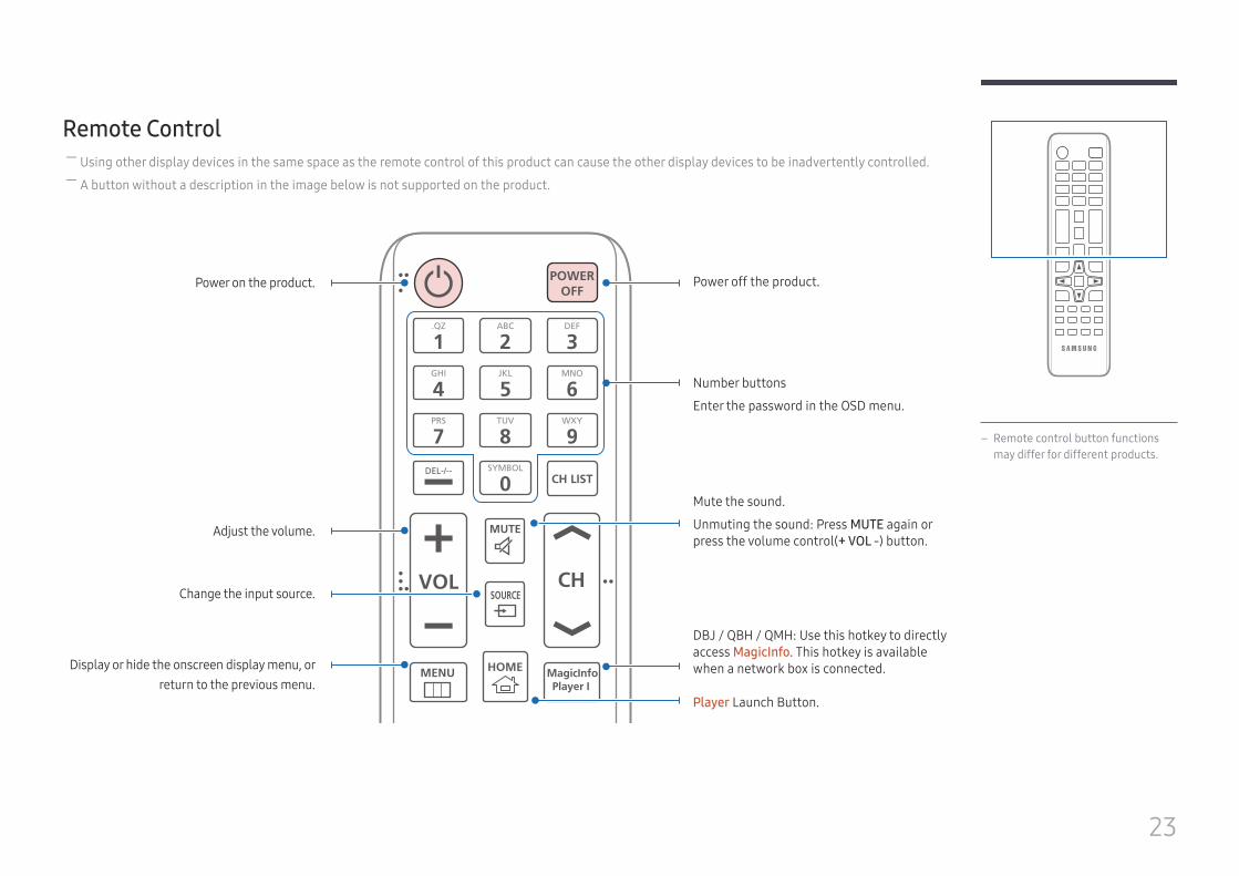


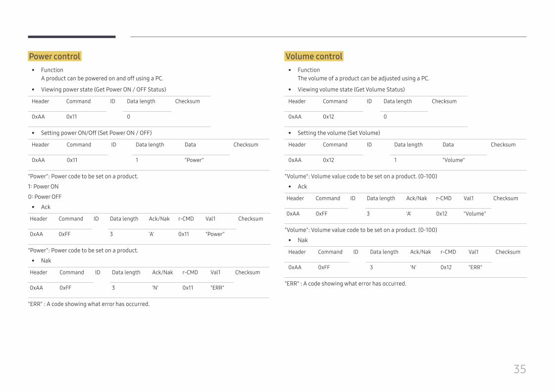


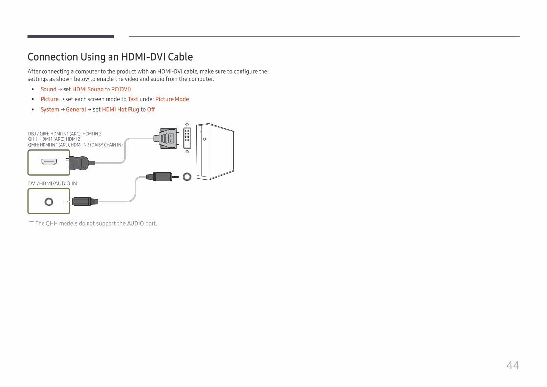


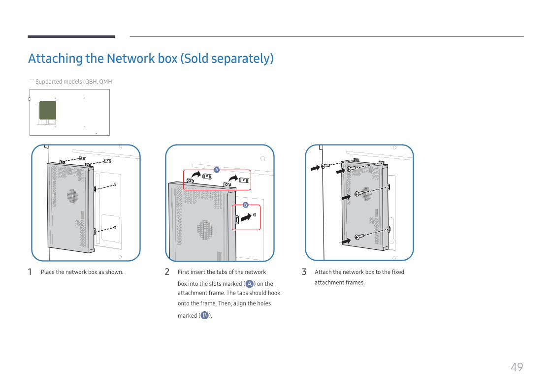


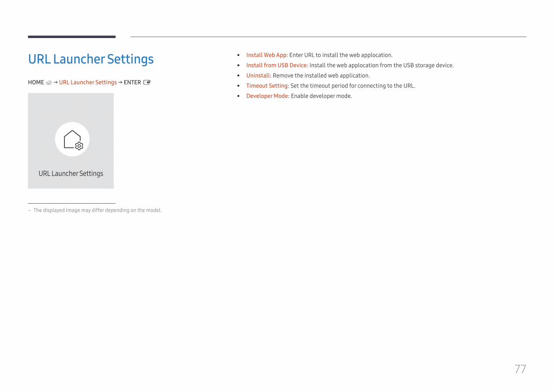


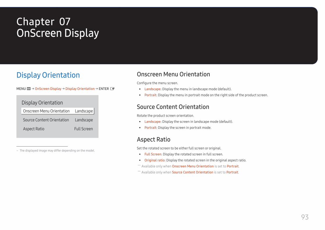


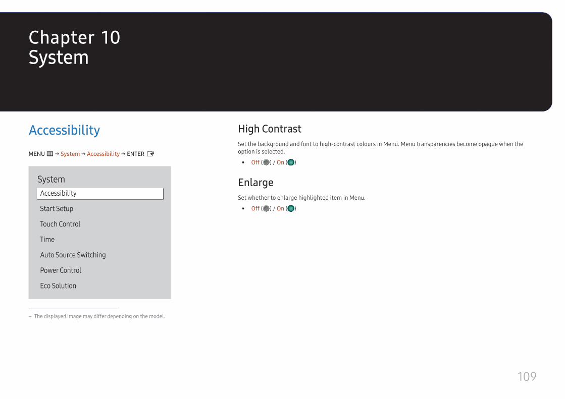


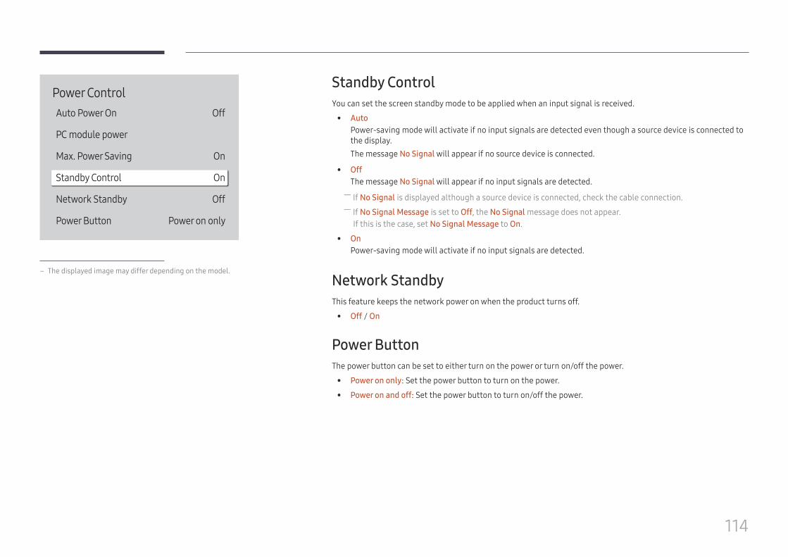


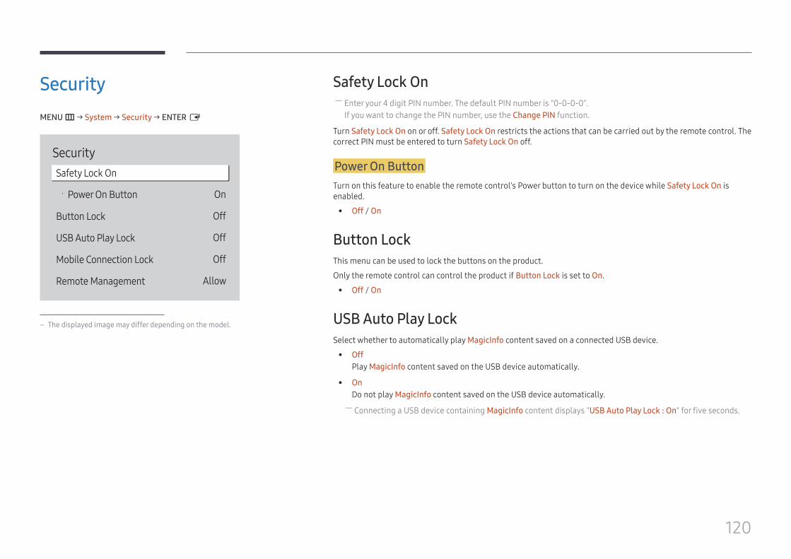


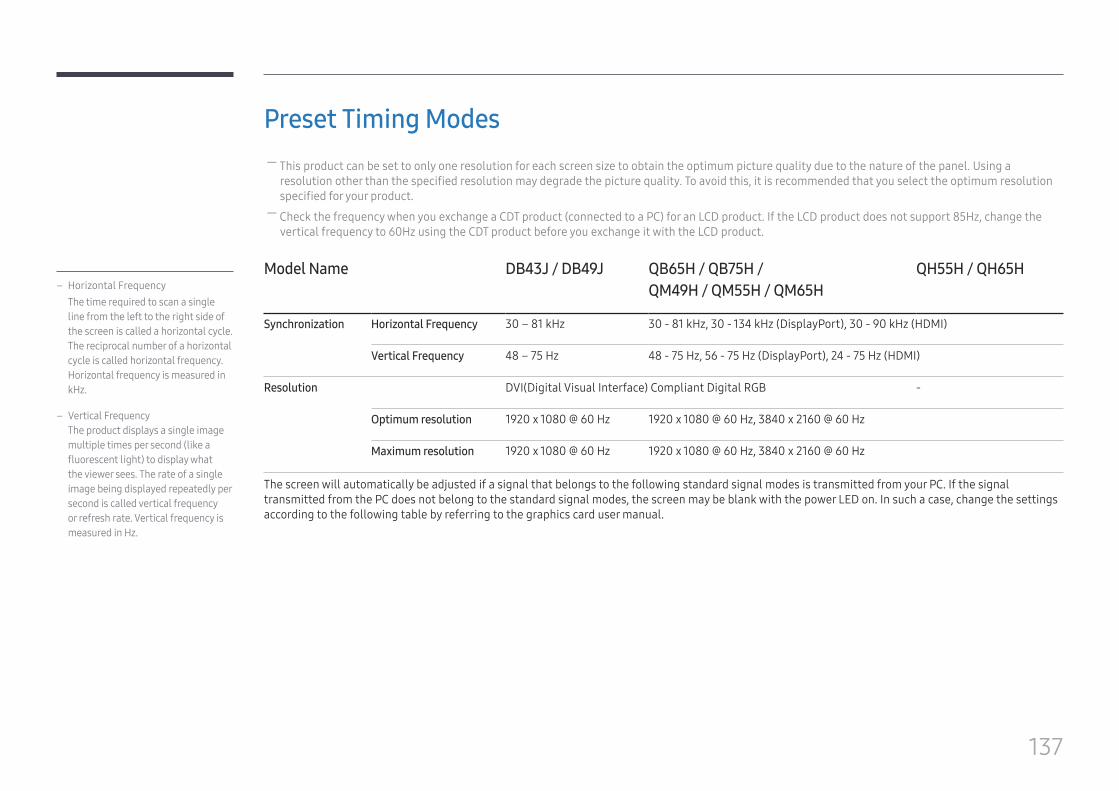


![PHYSICS FORM 4 [FORCE AND MOTION-CHAPTER 2 · PDF filePHYSICS FORM 4 [FORCE AND MOTION-CHAPTER 2] 5 Study Of Linear Motion Ticker-timer 1. In the laboratory, a ticker-timer as](https://static.documents.pub/doc/80x56/5a70d2347f8b9aac538c46e1/physics-form-4-force-and-motion-chapter-2-nbsppdf-filephysics-form.jpg)


