Asentria SiteBoss 550 User Manual Page 1 User Manual Installation and Operation Guidelines SiteBoss™ 550 Remote Site Manager Version 2.10.520 Rev. A Asentria Corporation 1200 North 96 th Street Seattle, Washington, 98103 U.S.A. Tel: 206.344.8800 Fax: 206.344.2116 www.asentria.com
Transcript
Asentria SiteBoss 550 User Manual
Page 1
User Manual
Installation and Operation Guidelines
SiteBoss™ 550 Remote Site Manager
Version 2.10.520 Rev. A
Asentria Corporation 1200 North 96th Street Seattle, Washington, 98103 U.S.A. Tel: 206.344.8800 Fax: 206.344.2116
SiteBoss 550 Remote Site Manager Installation and Operation Guidelines For Firmware Version 2.10.520 _STD Release date: Nov 2014
Conventions used in this manual The following are the conventions that will be used throughout this document:
Commands are printed in this format: COMMANDS (Arial font, caps, bold, black) although commands used in the unit are not case-sensitive.
Setting Keys are printed in this format: setting.key (Courier New font, bold, blue). Key values
displayed are in Courier New font, not bold, black.
Red type indicates a safety or security warning.
Hyperlinks to other sections in the manual are displayed in Arial, blue, underline.
Screen shots of menus taken from the command line interface appear like this:
CLI Example:
A) Example Setting [Example]
B) Example Setting [Example]
Some settings can only be changed with a Setting Key (no command line menu or web interface options). These are noted throughout Setup Menu section of the manual by Setting Key: <name
of key> with a description of the values and meaning.
For More Information If the information contained in this user manual is not sufficient to resolve a problem you are having with your unit or to fully explain a feature, there is likely a feature guide covering it in more depth. These feature guides are available on line on the Asentria Information Portal. Asentria Tech Support is also available to provide any assistance you might need.
Power Requirements & Options ............................................................................................................ 6 Power Up Sequence ............................................................................................................................. 8
Accessing the SiteBoss ......................................................................................................................... 9 Access via a Network Connection ......................................................................................................... 9 Default Passwords .............................................................................................................................. 11 Access via a Serial Connection ........................................................................................................... 11 Configuring Ethernet Settings via IO2 ................................................................................................. 12 Testing Network Connectivity .............................................................................................................. 12
What is a SiteBoss 550 ................................................................................................ 13 The Basics ............................................................................................................................................. 13
Communication Methods ..................................................................................................................... 13 Event Notification................................................................................................................................. 13 Data Storage ....................................................................................................................................... 14 Remote Access ................................................................................................................................... 14 Environmental Monitoring .................................................................................................................... 14 Data Events ......................................................................................................................................... 14 Audit Log ............................................................................................................................................. 15
Features and Accessories ................................................................................................................... 15 Standard Equipment ............................................................................................................................ 15 Optional Hardware .............................................................................................................................. 15 LEDs, Ports, Connectors, and Buttons ............................................................................................... 16
Navigating the Interface .............................................................................................. 20 Web Interface ......................................................................................................................................... 20
Navigating the Web Interface .............................................................................................................. 21 Settings Entry Functions ..................................................................................................................... 22
Status Pages .......................................................................................................................................... 24 Sensors ............................................................................................................................................... 24 Power Distribution ............................................................................................................................... 25
Settings Menu .............................................................................................................. 29 General ................................................................................................................................................... 29
General System ................................................................................................................................... 29 Location Tab ........................................................................................................................................ 31
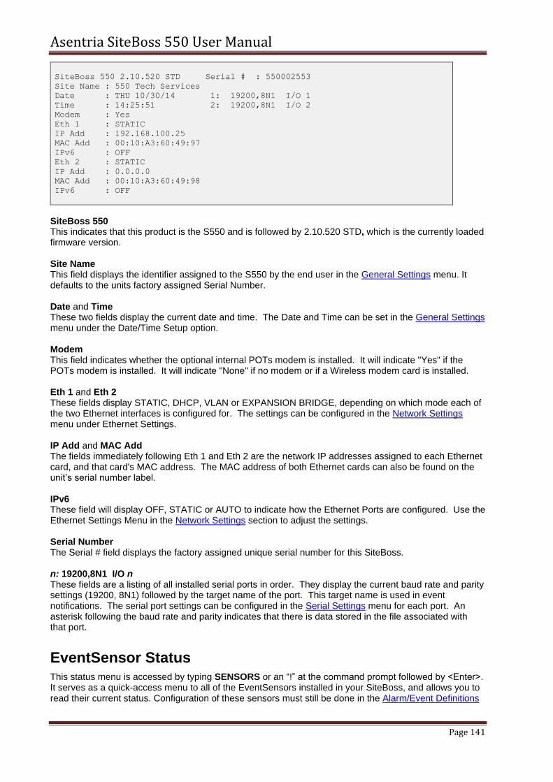
CLI Status Pages ................................................................................................................................. 140 General Status ................................................................................................................................... 140 EventSensor Status ........................................................................................................................... 141 Power Distribution Status .................................................................................................................. 142 Wireless Modem Status .................................................................................................................... 143 AC Power Monitors............................................................................................................................ 144
Internal Modem Guidelines ................................................................................................................ 167 Canadian Department of Communications ...................................................................................... 168 Warranty Information .......................................................................................................................... 169 Asentria Technical Support ............................................................................................................... 170
Asentria SiteBoss 550 User Manual
Page 6
Quick Start This is a brief guide to help get your SiteBoss 550 (S550) up and running quickly.
Hardware Needed Asentria SiteBoss 550
15VDC power adaptor (Included if AC power option)
DC power source (if DC power option)
Computer with a network port or a serial port and terminal emulation software
Ethernet cable
Optional, if connecting serially, RJ45 M-M unshielded serial cable and RJ45/DB9 straight thru adapter (included)
Information Needed IP address(es) to assign to the S550 if using static IP
Subnet mask
Default router IP or gateway router IP address if on a WAN (Optional)
Physically Install SiteBoss Physically install the SiteBoss into your site. Use the included Mounting Brackets to secure to a standardly grounded equipment rack. If the unit is not mounted within a grounded rack system, connect the attached ground wire securely to an appropriate earth ground. Connect an Ethernet cable into the RJ45 jack labeled ETH1.
Power Requirements & Options The S550 can be configured with one or two options for incoming power. The standard power option is the 15VDC power jack in the back of the unit. The supplied power jack connects via an AC power adaptor to a standard wall power plug. There is an optional 24VDC or -48VDC power which is supported on a DC power card installed in the rear panel of the unit. If using a DC power source, the unit is configured with a 4-pin Phoenix style connector for use with a DC power source. The unit is shipped with the instructions for direct connection to a DC power source. The instructions are shown below, in case they are missing from the box:
Standard 15VDC via AC Power
If you are using a standard AC wall plug, the unit uses a barrel connector for connecting to the 15VDC power adapter. This power option ships with the unit.
DC Power Card Wiring Instructions
This section describes the connection to the 30 watt DC power card, which supports either 24VDC or -48VDC power options, and features a Phoenix terminal block with screw clamp connectors. Wiring connections to DC power can be made using customer supplied wiring, or one of the two optional wiring kits that may be purchased with the unit.
Asentria SiteBoss 550 User Manual
Page 7
This unit should be assembled and installed by a qualified technician who can ensure the power source is an isolated, SELV (Safety Extra Low Voltage) circuit for -48VDC installations. The 24VDC option does require an isolated circuit.
Note: For DC powered systems, safety standards require that a disconnect device be provided as part of any permanent building installation. The DC input should be protected by an external 2A Slow Blow Fuse conforming to CSA/UL 248-14, IEC 60127-4/2, at the power supply or within the building circuitry. The input DC power current limiting fuse circuit is provided for by the end user, and is required for unit operation in compliance with safety agency approvals.
One example of a compliant fuse for the DC input is a Littelfuse 239P series, 2 amp fuse with a 250 VDC minimum voltage rating and interrupt rating 10,000 amps at 125 VAC, 0.7 to 0.8 power factor and 100 amps at 125VAC, 0.7-0.8 power factor.
Fig 1: 30 Watt DC Power Card The DC power supply option has 4 input connections. (See Fig. 1) This gives the user the ability to connect this unit to an auxiliary DC power source.
Caution: DANGER! FIRE HAZARD! DO NOT LEAVE AN UNCONNECTED WIRE EXPOSED!
DO NOT CONNECT THE UNIT TO ANY OTHER EQUIPMENT UNTIL YOU KNOW THE UNIT POWERS UP CORRECTLY!
Attention: Danger ! INCENDIE ! NE LAISSEZ PAS LES FILS NON CONNECTÉS EXPOSÉS ! NE PAS connecter l'appareil à tout autre équipement avant de savoir que l'appareil soit correctement!
Peripheral equipment connections may cause a short circuit of your power supply if the power connections are reversed. Do not connect peripheral equipment connections until you know the unit is operational by observing the front panel Power LED. If the polarity is reversed the Power LED will not light.
Note: DO NOT CONNECT THE UNIT TO ANY OTHER EQUIPMENT UNTIL YOU KNOW THE
UNIT POWERS UP CORRECTLY! A SiteBoss purchased with the DC power option can also be purchased with optional wiring kits. Each kit is described below with wiring connection instructions for -48VDC and 24VDC.
5006-026 10ft of black & white 20AWG wire
-48VDC Wiring
Connect the black and white 20AWG wires provided to your -48VDC voltage source: 1. Ensure the unit is not connected to any peripheral equipment.
NOTE: Peripheral equipment connections may cause a short circuit of your -48V supply if the power connections are reversed! Do not connect peripheral equipment connections until you know the unit is operational by observing the front panel Power LED is lit.
2. Strip the ends of the wires. 3. Connect the BLACK wire from the ground or the most Positive connection on the voltage source
to the A+ screw clamp on the power card terminal block.
Asentria SiteBoss 550 User Manual
Page 8
4. Connect the WHITE wire from the -48VDC or the most Negative connection on the voltage source to the A- screw clamp on the power card terminal block.
24VDC Wiring:
Connect the black and white 20AWG wires provided to your 24VDC voltage source: 1. Ensure the unit is not connected to any peripheral equipment.
NOTE: Peripheral equipment connections may cause a short circuit of your 24V supply if the power connections are reversed! Do not connect peripheral equipment connections until you know the unit is operational by observing the front panel Power LED is lit.
2. Strip the ends of the wires. 3. Connect the WHITE wire from the 24VDC or the most Positive connection on the voltage source
to the A+ screw clamp on the power card terminal block. 4. Connect the BLACK wire from the ground or the most Negative connection on the voltage source
to the A- screw clamp on the power card terminal block.
5006-025 35ft of black & red 18AWG wire, spade lugs and ring terminals
Or 5006-029 10ft of black & red 18AWG wire
-48VDC Wiring
Connect the red and black 18AWG wires provided to your -48VDC voltage source: 1. Ensure the unit is not connected to any peripheral equipment.
NOTE: Peripheral equipment connections may cause a short circuit of your -48V supply if the power connections are reversed! Do not connect peripheral equipment connections until you know the unit is operational by observing the front panel Power LED is lit.
2. Strip the ends of the wires. 3. Connect the BLACK wire from the ground or the most Positive connection on the voltage source
to the A+ screw clamp on the power card terminal block. 4. Connect the RED wire from the -48VDC or the most Negative connection on the voltage source
to the A- screw clamp on the power card terminal block.
24VDC Wiring
Connect the red and black 18AWG wires provided to your 24VDC voltage source: 1. Ensure the unit is not connected to any peripheral equipment.
NOTE: Peripheral equipment connections may cause a short circuit of your 24V supply if the power connections are reversed! Do not connect peripheral equipment connections until you know the unit is operational by observing the front panel Power LED is lit.
2. Strip the ends of the wires. 3. Connect the RED wire from the 24VDC or the most Positive connection on the voltage source to
the A+ screw clamp on the power card terminal block. 4. Connect the BLACK wire from the ground or the most Negative connection on the voltage source
to the A- screw clamp on the power card terminal block.
If there are any questions concerning this Wiring Instruction Sheet, or connecting your Asentria product to DC power, please contact Asentria Technical Support.
Power Up Sequence On startup, the S550 goes through the following boot sequence in approximately 55 seconds: 1) The power LED flashes once each second for 30 seconds. 2) The LEDs for Expansion Card 1 go through a 15 second flashing sequence. 3) All LED’s then go off for approximately 5 seconds. 4) Power, Modem (if installed) and Ethernet LEDs light for 5 seconds, then Modem and Ethernet go off. 5) Power LED will blink once every 5 seconds as a "heartbeat" while the SiteBoss is powered on.
Asentria SiteBoss 550 User Manual
Page 9
Accessing the SiteBoss The SiteBoss has two interface options for command and control. There is an intuitive Web Interface that can be accessed via the Ethernet connection at ETH1 or via an optional wireless modem card. The SiteBoss can also be access via a Command Line Interface that can be accessed via Telnet or a serial connection.
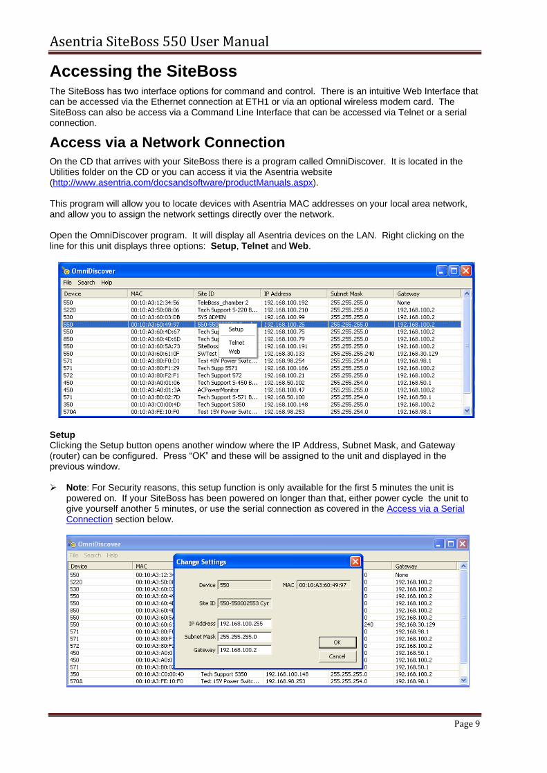
Access via a Network Connection On the CD that arrives with your SiteBoss there is a program called OmniDiscover. It is located in the Utilities folder on the CD or you can access it via the Asentria website (http://www.asentria.com/docsandsoftware/productManuals.aspx). This program will allow you to locate devices with Asentria MAC addresses on your local area network, and allow you to assign the network settings directly over the network. Open the OmniDiscover program. It will display all Asentria devices on the LAN. Right clicking on the line for this unit displays three options: Setup, Telnet and Web.
Setup Clicking the Setup button opens another window where the IP Address, Subnet Mask, and Gateway (router) can be configured. Press “OK” and these will be assigned to the unit and displayed in the previous window.
Note: For Security reasons, this setup function is only available for the first 5 minutes the unit is
powered on. If your SiteBoss has been powered on longer than that, either power cycle the unit to give yourself another 5 minutes, or use the serial connection as covered in the Access via a Serial Connection section below.
Web Once the IP address has been assigned, clicking the Web button opens an HTTP (web) connection to the device using your default browser. See the Default Password section for log in instructions. The Web Interface can also be reached by typing the configured IP address into an internet browser's address bar.
Note: For Internet Explorer users: Asentria Firmware version after 2.10.520 will require that the "Use TLS 1.1" box be checked to access your SiteBoss. Click the Settings wheel in the top right hand corner and then select Internet Options. Choose the "Advanced" tab and navigate to the bottom of the Advanced options box. Ensure the "Use TLS1.1" box is checked and, if not, check the box and click OK.
Telnet Once the IP address has been configured, clicking the Telnet button will open a connection to the SiteBoss' Command Line Interface using your default Telnet client, if one is configured for your operating system. If a Telnet client has not been configured for your Windows operating system:
Open a command prompt window on your computer or laptop. Click the Start icon, type CMD in the Start Search box, and then press ENTER.
At the computer's command prompt type the following command: pkgmgr /iu:"TelnetClient"
If the User Account Control dialog box appears, confirm that the action it displays is what you want, and then click Continue.
When the command prompt appears again, the installation is complete. Once the Telnet Client has been installed on your computer or lap top, the SiteBoss' Command Line Interface should be accessible by selecting the Telnet button. Or, you can simply navigate from your computer's command window:
Type "Telnet" at the Windows command prompt.
Then type "Open <IP Address>". This will take you to the SiteBoss Command Interface. See the Default Password section for login instructions.
See the Command Line Interface section for instructions on how to control your SiteBoss using this interface.
To exit from the SiteBoss Command Line Interface type bye.
To exit from the Windows Telnet client type quit.
Contact Asentria Technical Support for any questions or assistance with OmniDiscover. Refer to the Telnet Feature Guide on the Asentria Information Portal for further information regarding a number of different types of Telnet connection options.
Default Passwords The SiteBoss uses a very flexible system for managing users, passwords, and access rights. By default, the User1 profile is the only one with a preconfigured username and password. The User Name is admin and the Password is password. For security reasons it is highly recommended that you change the password, and record all configured passwords in a secure location. The username and passwords are configured in the Security menu under User Profiles.
Access via a Serial Connection An alternate way to access your SiteBoss is using a serial port. This will allow an immediate connection to the Command Line Interface of the SiteBoss. The Serial Port labeled I/O2 is configured for command access by default. For a serial connection to a Console Port of a PC or laptop running any terminal emulator: USB Com port For a USB connection, a USB to RS232 adapter will be needed. This is Asentria part no. 4161-021.
a. Connect the USB adapter to a USB port on your computer. b. Connect the DCE adapter (supplied with the SiteBoss) to the RS232 end of the adapter. c. Use an RJ45 cable to connect the DCE adapter to the SiteBoss I/O2 port.
RJ45 or DB9 Interface Com Port
a. Connect the RJ-45 serial cable to the SiteBoss I/O 2 b. Connect the DTE adaptor (supplied with the SiteBoss) to the other end of the cable. c. If your computer has a DB9 interface port, that adapter can connect directly to a serial com
port. d. If your computer or laptop has a RJ-45 style interface, connect the DCE adapter (supplied
with the SiteBoss) to the DTE adapter and connect the second supplied serial cable from the DCE adapter to your computer com port.
Note: If both LEDs on the SiteBoss I/O 2 port do not light, add the null modem adapter (supplied with
the SiteBoss) between the adapters. Connect to that serial port using any terminal emulator such as TeraTerm (http://ttssh2.sourceforge.jp/index.html.en) or Putty (http://www.extraputty.com/). I/O 2 is set to 19200 baud, 8N1 (8 data bits, no parity, 1 stop bit, no flow control) by default. From the command prompt enter STATUS and press <Enter>. You will be presented with a Status screen similar to the following. When the Status screen appears, the unit is successfully connected and ready for use. See the Command Line Interface chapter for information on how to configure and control functions of the SiteBoss via this interface.
> status SiteBoss 550 2.10.520 STD Serial # : 550002553
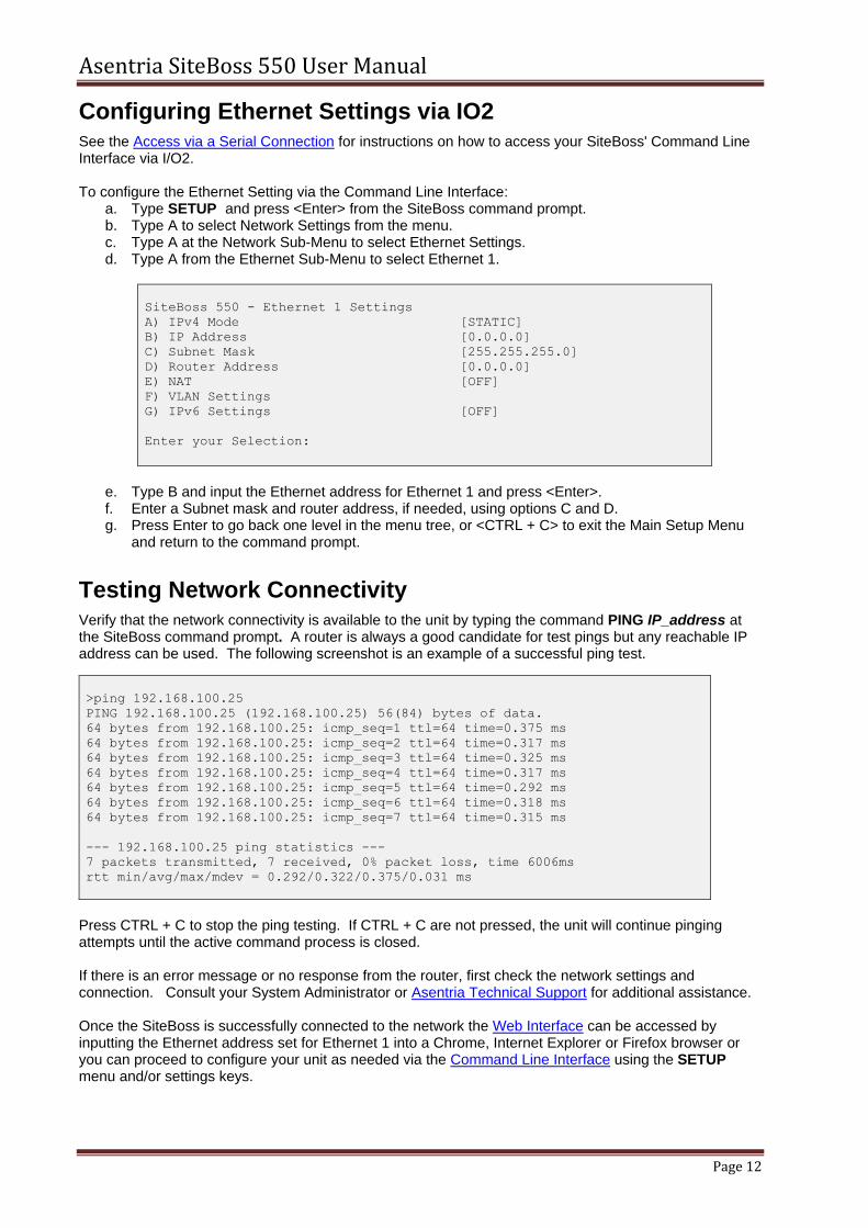
Configuring Ethernet Settings via IO2 See the Access via a Serial Connection for instructions on how to access your SiteBoss' Command Line Interface via I/O2. To configure the Ethernet Setting via the Command Line Interface:
a. Type SETUP and press <Enter> from the SiteBoss command prompt. b. Type A to select Network Settings from the menu. c. Type A at the Network Sub-Menu to select Ethernet Settings. d. Type A from the Ethernet Sub-Menu to select Ethernet 1.
SiteBoss 550 - Ethernet 1 Settings
A) IPv4 Mode [STATIC]
B) IP Address [0.0.0.0]
C) Subnet Mask [255.255.255.0]
D) Router Address [0.0.0.0]
E) NAT [OFF]
F) VLAN Settings
G) IPv6 Settings [OFF]
Enter your Selection:
e. Type B and input the Ethernet address for Ethernet 1 and press <Enter>. f. Enter a Subnet mask and router address, if needed, using options C and D. g. Press Enter to go back one level in the menu tree, or <CTRL + C> to exit the Main Setup Menu
and return to the command prompt.
Testing Network Connectivity Verify that the network connectivity is available to the unit by typing the command PING IP_address at the SiteBoss command prompt. A router is always a good candidate for test pings but any reachable IP address can be used. The following screenshot is an example of a successful ping test.
>ping 192.168.100.25
PING 192.168.100.25 (192.168.100.25) 56(84) bytes of data.
64 bytes from 192.168.100.25: icmp_seq=1 ttl=64 time=0.375 ms
64 bytes from 192.168.100.25: icmp_seq=2 ttl=64 time=0.317 ms
64 bytes from 192.168.100.25: icmp_seq=3 ttl=64 time=0.325 ms
64 bytes from 192.168.100.25: icmp_seq=4 ttl=64 time=0.317 ms
64 bytes from 192.168.100.25: icmp_seq=5 ttl=64 time=0.292 ms
64 bytes from 192.168.100.25: icmp_seq=6 ttl=64 time=0.318 ms
64 bytes from 192.168.100.25: icmp_seq=7 ttl=64 time=0.315 ms
--- 192.168.100.25 ping statistics ---
7 packets transmitted, 7 received, 0% packet loss, time 6006ms
rtt min/avg/max/mdev = 0.292/0.322/0.375/0.031 ms
Press CTRL + C to stop the ping testing. If CTRL + C are not pressed, the unit will continue pinging attempts until the active command process is closed. If there is an error message or no response from the router, first check the network settings and connection. Consult your System Administrator or Asentria Technical Support for additional assistance. Once the SiteBoss is successfully connected to the network the Web Interface can be accessed by inputting the Ethernet address set for Ethernet 1 into a Chrome, Internet Explorer or Firefox browser or you can proceed to configure your unit as needed via the Command Line Interface using the SETUP menu and/or settings keys.
Asentria SiteBoss 550 User Manual
Page 13
What is a SiteBoss 550
Fig 2: SiteBoss 550 (S550-2 on top, S550-6 on bottom)
The Basics The SiteBoss 550 is a versatile system used for monitoring and control of remote equipment sites. The S550 provides remote monitoring of serial devices, equipment I/O, and environmental conditions at these remote sites and forwards notification when conditions fall outside user defined limits. On-board I/O provides serial, Ethernet, and modem connectivity. The S550-2 (11-inch) and S550-6 (17-inch) models provide two or six expansion slots respectively to allow the addition of various communications and monitoring interfaces (Expansion Cards).
Communication Methods The S550 has a diverse selection of communication methods available for different applications. The following methods can be used to either access the command processor or provide a pass-through connection to devices attached to the serial ports. All methods of connecting to the unit can be secured via password for protection of data and hardware.
HTTP
HTTPS
RS-232 serial
Optional RS485 serial
Telnet (Up to 8 sessions simultaneously)
SSH
Standard modem serial
Optional wireless modem
Security callback modem serial
SNMP get/set
Data may be retrieved from or through the S550 by any of the following methods:
Web Interface Status and Logs menus
Serial or modem connection to command processor (using Line or Zmodem) or pass-through
Telnet to command processor or pass-through
Telnet real-time sockets
FTP push (automatic delivery to FTP server)
FTP get (manual retrieval from FTP server)
SFTP push/get
SNMP get/set
DNP3 Outstation via TCP only
Event Notification Sensor event alarms generated or detected within the S550 can be delivered through any of the following means:
SNMP trap or inform
Email
Relay or Power Output toggles
Asentria SiteBoss 550 User Manual
Page 14
Script actions
SMS Messages
POTS Modem callout
Dialup pager or Dispatch via POTS modem
Asentria Alarms (TCP or POTS Modem)
Data Storage Basic data storage in the S550 is accomplished in a database of four files – FILE1, FILE2, EVENTS, and AUDIT. FILE1 and FILE2 are typically associated with Serial Port I/O 1 and Serial Port I/O 2, respectively, although either serial port can store to FILE1, FILE2, or both. EVENTS and AUDIT are log files generated from the Event Log Settings and Audit Log Settings menus per the parameters set there. If the unit has additional serial ports via a slot card, a FILE location will be available for each port. The number of records stored in each of these files can be displayed using the DIR command on any connection to the command line interface. The S550 also features three “auxiliary” files for storage of data to be used in scripting functions, named AUX1, AUX2, and AUX3. These three files are not displayed with the DIR command, although data collected via serial port can be stored to any of these three auxiliary files in addition to FILE1 and FILE2. For further explanation about processing data stored in AUX1, AUX2 and AUX3, refer to the Configuring and Using LUA Scripting Feature Guide on the Asentria Product Information Portal. Contact Asentria Technical Support for more information.
Remote Access The S550 can provide an administrator transparent access to devices connected to the serial ports of the unit via pass-through connections or through the login menu in the web interface, Telnet, and modem connections. This sort of access can be used to configure, maintain, or manipulate devices that would normally have no remote access. The SiteBoss has a Port Forwarding feature that allows the configuration to accept UDP and TCP frames on an interface and route them, translating their IP addresses and UDP/TCP ports according to configuration to a different address, even on a different network interface, than the request was received on. The SiteBoss can proxy SNMP PDUs to another agent. In other words, the unit responds to inbound SNMP PDUs on behalf of another agent. This facilitates a user to utilize the unit as the interchange between remote devices via SNMP where routing or port forwarding is not an option. With some custom scripts the SiteBoss can communicate via MODBUS RTU to connected equipment. Additionally, the unit can use XML Proxying and display sensor readings from connected equipment.
Environmental Monitoring Through the use of external EventSensor modules and/or internal Expansion Cards, a variety of environmental sensor monitoring and alarming capabilities are available in the SiteBoss. Each individual sensor can be configured with independent actions, counters and other unique settings. Sensor events triggered within the SiteBoss can be logged to an Event Log. This file can be viewed via the web interface, FTP, the Command Line Interface SETUP menu and the TYPE EVENTS command from the command prompt.
Data Events The S550 has the capability to monitor incoming data for user-defined strings and then report the event via several avenues. The S550 allows for up to 1000 different data events. Each data event contains independent actions, counters, and other unique settings. Data events triggered within the S550 can be logged to an Event Log. This file can be viewed through the Event Log on the web interface Logs section
or via the Command Interface SETUP menu, FTP, or from the command prompt TYPE EVENTS command.
Audit Log The S550 has the ability to log many types of administrative events, from serial port handshaking alarms to login attempts. These Audit Log entries are stored in a file and can be viewed in the web interface in the Logs section or via the Command Line Interface SETUP menu, FTP, or from the command prompt TYPE AUDIT command.
Features and Accessories
Standard Equipment The base S550 comes with the following standard on-board equipment:
AC power input
32MB logging database for text records
2 – RJ45 DTE serial I/O ports
1 – RJ45 Sensor port for connection of EventSensors and SensorJack Sensors
2 – 10/100Mb Ethernet interfaces with support for six 802.1Q VLAN interfaces on each
1 – MMC memory I/O slot
2 or 6 – Expansion Card slots
1 – Reset button
Internal lithium coin-cell type battery backup* * Battery backup preserves clock operation when power is not present. Data records and settings
are stored in non-volatile memory and therefore do not require battery backup. CAUTION: THERE IS A RISK OF EXPLOSION IF THE BATTERY IS REPLACED BY AN
INCORRECT TYPE. Replace with batteries of the same type or as recommended by the manufacturer. Dispose of used batteries according to the instructions.
ATTENTION: II y a danger d’explosion s’il y a remplacement incorrect de la batterie. Remplacer
uniquement avec une batterie du même type ou d’un type equivalent recommandé par le constructeur. Mettre au rebut les batteries usagées conformément aux instructions du fabricant.
In addition to the above standard on-board equipment, the S550 may be shipped with the following accessories:
This product manual on the Documentation and Software CD
External desktop power supply with US-type IEC Card (if AC specified on order)
DC Installation Kit (if DC specified on order)
1 – 6ft RJ45 Ethernet cable
2 – 6ft RJ45 M-M unshielded serial cable serial cables
1 – RJ45/DB9 Male DTE Adaptor
1 – RJ45/DB9 Female DCE Adaptor
1 – DB9M/DB9F Null Modem Adaptor
Rack mount ears
Screwdriver and terminal blocks for Expansion Cards with internal contacts
Optional Hardware The SiteBoss has a wide variety of optional cards and accessories. Options include DC Power Input and a DC Power Installation Kit, 64MB logging database for text records, an internal POTS modem, as well as a Run-time battery option. The various optional internal slot cards have appropriate wiring and accessories including with the shipment.
Asentria SiteBoss 550 User Manual
Page 16
I/O points and Expansion Cards
Fig 3: Expansion Card The expansion cards in the two or six expansion card slots can be configured with multiple options. The terminal block ports will be marked to indicate how the slot card is configured. A single card can have more than one type of I/O option.
C – Standard Contact Closure Input CI – Isolated Contact Closure Input V – Analog Voltage Input VI – Isolated Voltage Input M – 4-20mA Current Input MI – Isolated 4-20mA Sensor R – Low-Current Form A Relay SR – Solid State Relay RC – Form C Relay F – Resistive Fuel Sensor P – +/-15 VDC Power Output P5 – + 5 VDC Power Output W – Wiegand Access Control
Other types of cards can be installed into the expansion card slots including:
Wireless Modem 4X Serial Port 2X RS485 2X RS232 Serial Port 4X Ethernet Port 64C High-Density Expansion Card 32C8V8R High-Density Expansion Card GPS receiver
Fig 4: Wireless Modem Fig 5: Serial Port Card Fig 6: High-Density I/O Card
LEDs, Ports, Connectors, and Buttons
Front Panel - LEDs
Fig 7: Front panel S550-2 (11”- wide model)
Asentria SiteBoss 550 User Manual
Page 17
PWR (Power) The Power LED is green and has two operational states. During the boot up cycle, it will blink once every second until the boot sequence is complete. During normal operation, it is steady on with a blink every 5 seconds. MDM (Modem) The MDM LED lights a solid green whenever the POTS modem is connected and blinks when the modem is dialing out. ETH (Ethernet) The Link LED lights solid green whenever an active Telnet or FTP connection is made to the unit. ALM (Alarm) This LED is reserved for future use. 25% - 75% - 100% The S550 has three LEDs to indicate file full status. A blinking percentage full LED indicates the database has less than the amount indicated by that LED, but more than the previous. A solid lit LED indicates the database percentage is at or over the value for that LED. Expansion Card n Each optional Expansion Card has eight LEDs associated with it that may or may not be used.
Back Panel
Fig 8: Back panel S550-6 (17”- wide model)
The S550 back panel is configured (from right to left) with a bay for the optional run-time battery or DC power card, AC power jack, RJ45 Sensor port, bank of 8 DIP switches, MMC memory I/O card slot, two RJ45 Ethernet ports, two RJ45 RS232 serial ports, Reset button, one RJ11 POTS modem port, and either two or six expansion bays for optional Expansion Cards that expand the functionality of the unit with wireless modem and/or a variety of sensor and relay I/O.
LEDs – Back Panel
Fig 9: LEDs I/O and Ethernet Ports
The Serial I/O ports and the Ethernet ports on the back panel each has two LEDs associated with it – one on the Right of the port, one on the Left. Ethernet Ports (ETH1 and ETH2)
● Right – Lights solid red when an Ethernet cable is connected to the port and an active Ethernet network. The LED is off when the cable is disconnected from the network, or the Ethernet Port. ● Left – Flashes yellow/green when network data (TCP packets) is being transmitted or received across the port. When no data is actually being transmitted/received, this LED is off.
Asentria SiteBoss 550 User Manual
Page 18
I/O Port 1 & 2 (and any additional 4-I/O Port cards that may be installed) ● Right – Lights solid green when a correctly configured cable from another device is connected to it. Otherwise this LED remains off. As the I/O Port receives or transmits data, this LED will flash red. ● Left – Lights solid green when power is applied to the S550, regardless of whether a cable is connected to the I/O Port or not.
Ports
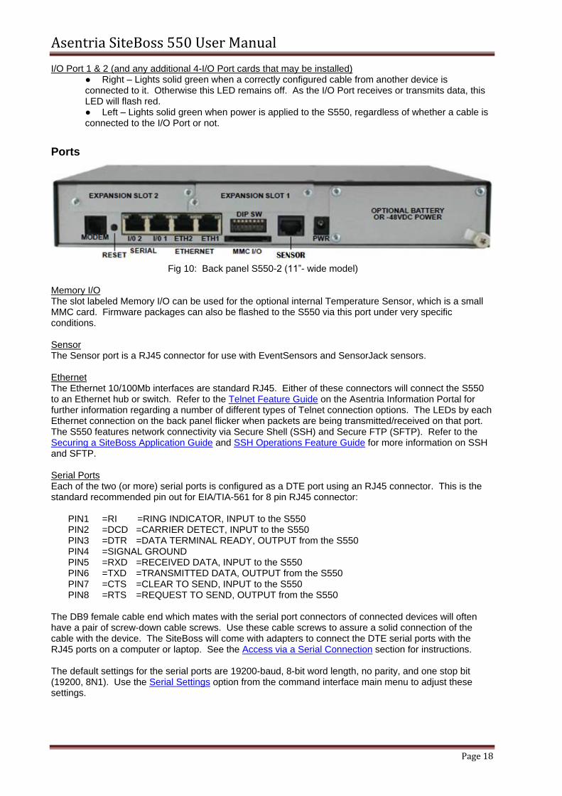
Fig 10: Back panel S550-2 (11”- wide model)
Memory I/O The slot labeled Memory I/O can be used for the optional internal Temperature Sensor, which is a small MMC card. Firmware packages can also be flashed to the S550 via this port under very specific conditions. Sensor The Sensor port is a RJ45 connector for use with EventSensors and SensorJack sensors. Ethernet The Ethernet 10/100Mb interfaces are standard RJ45. Either of these connectors will connect the S550 to an Ethernet hub or switch. Refer to the Telnet Feature Guide on the Asentria Information Portal for further information regarding a number of different types of Telnet connection options. The LEDs by each Ethernet connection on the back panel flicker when packets are being transmitted/received on that port. The S550 features network connectivity via Secure Shell (SSH) and Secure FTP (SFTP). Refer to the Securing a SiteBoss Application Guide and SSH Operations Feature Guide for more information on SSH and SFTP. Serial Ports Each of the two (or more) serial ports is configured as a DTE port using an RJ45 connector. This is the standard recommended pin out for EIA/TIA-561 for 8 pin RJ45 connector:
PIN1 =RI =RING INDICATOR, INPUT to the S550 PIN2 =DCD =CARRIER DETECT, INPUT to the S550 PIN3 =DTR =DATA TERMINAL READY, OUTPUT from the S550 PIN4 =SIGNAL GROUND PIN5 =RXD =RECEIVED DATA, INPUT to the S550 PIN6 =TXD =TRANSMITTED DATA, OUTPUT from the S550 PIN7 =CTS =CLEAR TO SEND, INPUT to the S550 PIN8 =RTS =REQUEST TO SEND, OUTPUT from the S550
The DB9 female cable end which mates with the serial port connectors of connected devices will often have a pair of screw-down cable screws. Use these cable screws to assure a solid connection of the cable with the device. The SiteBoss will come with adapters to connect the DTE serial ports with the RJ45 ports on a computer or laptop. See the Access via a Serial Connection section for instructions. The default settings for the serial ports are 19200-baud, 8-bit word length, no parity, and one stop bit (19200, 8N1). Use the Serial Settings option from the command interface main menu to adjust these settings.
Internal Modem If a dialup POTS modem is installed, an RJ-11 (typical U.S. phone) connector is used. A POTS (analog) dialup phone line is inserted into this connector. The modem installed within this unit is FCC certified. For further information, consult the Internal Modem Guidelines appendix or the serial number label. CAUTION: To reduce the risk of fire, use only No. 26 AWG or larger telecommunication line cord.
ATTENTION: Pour réduire les risques d’incendie, utilizer uniquement des conducteurs de
télécommunications 26 AWG au de section supérleure. Expansion Card Bays The S550 features two or six Expansion Card bays in which optional Expansion Cards can be installed to expand the capabilities of the S550. See the I/O points and Expansion Cards section of this manual for more information on Expansion Cards.
DIP Switches
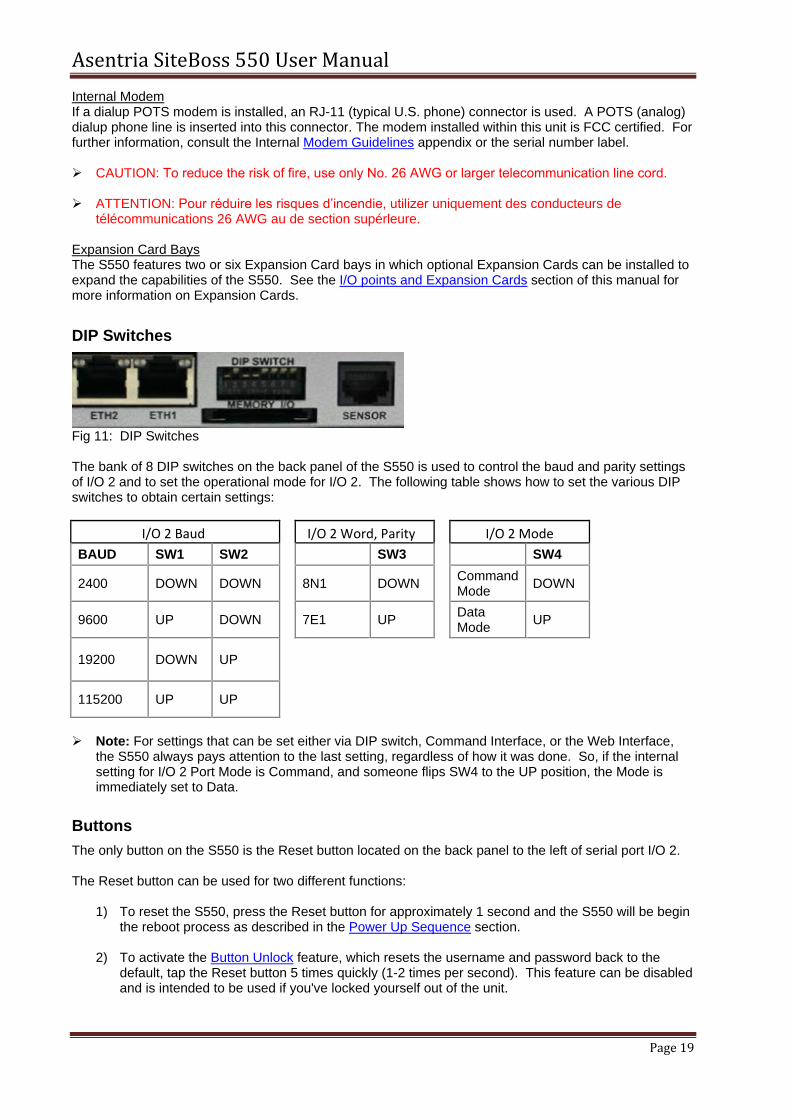
Fig 11: DIP Switches The bank of 8 DIP switches on the back panel of the S550 is used to control the baud and parity settings of I/O 2 and to set the operational mode for I/O 2. The following table shows how to set the various DIP switches to obtain certain settings:
I/O 2 Baud
I/O 2 Word, Parity
I/O 2 Mode
BAUD SW1 SW2
SW3
SW4
2400 DOWN DOWN
8N1 DOWN
Command Mode
DOWN
9600 UP DOWN
7E1 UP
Data Mode
UP
19200 DOWN UP
115200 UP UP
Note: For settings that can be set either via DIP switch, Command Interface, or the Web Interface,
the S550 always pays attention to the last setting, regardless of how it was done. So, if the internal setting for I/O 2 Port Mode is Command, and someone flips SW4 to the UP position, the Mode is immediately set to Data.
Buttons
The only button on the S550 is the Reset button located on the back panel to the left of serial port I/O 2. The Reset button can be used for two different functions:
1) To reset the S550, press the Reset button for approximately 1 second and the S550 will be begin the reboot process as described in the Power Up Sequence section.
2) To activate the Button Unlock feature, which resets the username and password back to the
default, tap the Reset button 5 times quickly (1-2 times per second). This feature can be disabled and is intended to be used if you've locked yourself out of the unit.
Asentria SiteBoss 550 User Manual
Page 20
Navigating the Interface There are two interface options for command and control of your SiteBoss. The Web Interface is an intuitive GUI interface that can be used for routine control and maintenance of your SiteBoss via HTTP or HTTPS using up to date versions of Chrome, Firefox, or Internet Explorer. The Command Line Interface can be reach via Serial, Telnet or SSH interface options. Some advanced debugging or control functions can only be accomplished via the Command Line Interface.
Note: For Internet Explorer users: Asentria Firmware version after 2.10.520 will require that the "Use TLS 1.1" box be checked to access your SiteBoss. Click the Settings wheel in the top right hand corner and then select Internet Options. Choose the "Advanced" tab and navigate to the bottom of the Advanced options box. Ensure the "Use TLS1.1" box is checked and, if not, check the box and click OK.
Web Interface The S550 has a built-in HTTP web server that can be used to configure the unit from anywhere the unit can be accessed on the network or Internet. This interface is enabled by default. Simply connect to http://<IP address of S550> or https://<IP address of S550> to use Secure Sockets Layer (SSL). Upon connection, you will be greeted by a login screen. Log in with your Login ID (Username) and Password. These are the same credentials you would use to log into the command prompt. By default the user name is admin and the password is password. It is highly recommended that the master password be changed via the User Profiles option from the Security menu.
Asentria SiteBoss 550 User Manual
Page 21
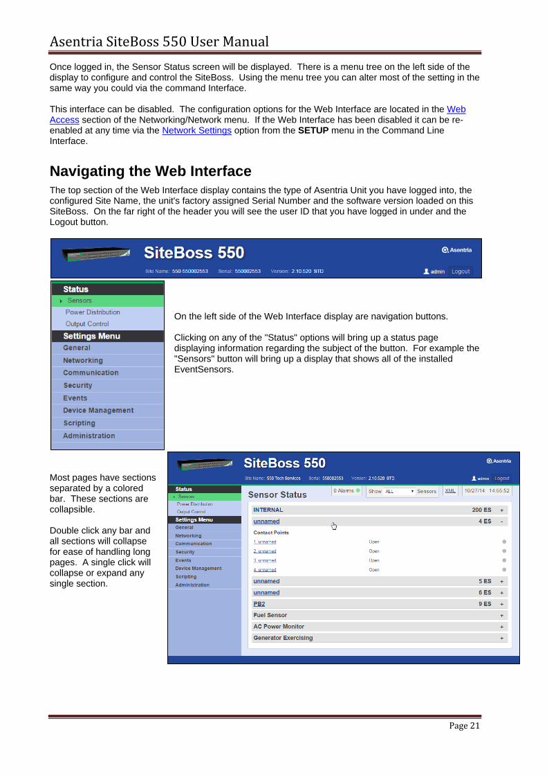
Once logged in, the Sensor Status screen will be displayed. There is a menu tree on the left side of the display to configure and control the SiteBoss. Using the menu tree you can alter most of the setting in the same way you could via the command Interface. This interface can be disabled. The configuration options for the Web Interface are located in the Web Access section of the Networking/Network menu. If the Web Interface has been disabled it can be re-enabled at any time via the Network Settings option from the SETUP menu in the Command Line Interface.
Navigating the Web Interface The top section of the Web Interface display contains the type of Asentria Unit you have logged into, the configured Site Name, the unit's factory assigned Serial Number and the software version loaded on this SiteBoss. On the far right of the header you will see the user ID that you have logged in under and the Logout button.
On the left side of the Web Interface display are navigation buttons. Clicking on any of the "Status" options will bring up a status page displaying information regarding the subject of the button. For example the "Sensors" button will bring up a display that shows all of the installed EventSensors.
Most pages have sections separated by a colored bar. These sections are collapsible. Double click any bar and all sections will collapse for ease of handling long pages. A single click will collapse or expand any single section.
Asentria SiteBoss 550 User Manual
Page 22
The buttons in the Settings Menu section will bring up a submenu of options under the subject heading listed. Clicking on one of the submenu options will change the page display, bringing up the settings page for the subject selected.
Settings Entry Functions There are several different types of entry options for adjusting settings via the Web Interface.
Checkbox
Checkboxes are common for enabling and disabling settings. They are ON/OFF type options. A check means ON. Click on the square to turn the option on or off.
Information Pop Up
Hovering over certain settings will cause informational pop up boxes to appear. These are designed to supply extra detail about the option.
String Entry
String Entry fields are locations where you can type in text, such as a description. Site names, for example, are user definable descriptions that will display in Emails and Traps as well as displaying at the top of the web interface menu screen. This type of entry field will quite often have a default description. You can delete the default and type in your own unique descriptive text string. These usually have a maximum field size, which varies. The field sizes are defined in the function section of the user manual and will be truncated if oversized.
Asentria SiteBoss 550 User Manual
Page 23
Drop-Down Menu
Another common input option is drop-down menu boxes. These typically give three or more options to choose from. Click the desired option and it will show in the display box.
Submit Button
Once you make a change to a setting, two buttons will appear in the upper right section of the page. If you are satisfied with the changes that you have made, click the Submit button. If you want to cancel the changes, and revert the settings to what they were before, click the "Cancel Changes" button.
Note: Take care when making changes to Networking Settings. These changes are made
immediately once the Submit button is clicked. The network connection could be lost and you will have to reconnect using the new configuration.
Notice Boxes
The unit will give informational type notices at the top of the page. These are color coded notices for the user. Informational notices, such as the unit letting you know something was completed successfully, will be in green. The notice will display for a few moments and disappear. The "x" can be clicked at any time to close the notice.
Yellow is a warning color. It will contain a message regarding a system settings change that needs to be adjusted. Warning notices will also display for a few moments and then disappear. The "x" can be clicked at any time to close the notice. A message in red is a warning that the action attempted failed. Red warning notices stay at the top of the screen until manually closed by the user by clicking the "x" on the right hand side of the notice. The setting that failed will have the entry field colored red to denote the error.
Alternate Settings Fields
There are some locations which have menu options in the upper sections of the page, which when clicked, change the available options in the lower entry fields.
Asentria SiteBoss 550 User Manual
Page 24
The name of the section whose settings are now displayed in the lower settings section will be in the header over that section. To change the settings to another of the available menu options, simply click the menu hyperlink and the settings fields for the selected menu option will display below. Save your changes before moving to another menu page.
Status Pages
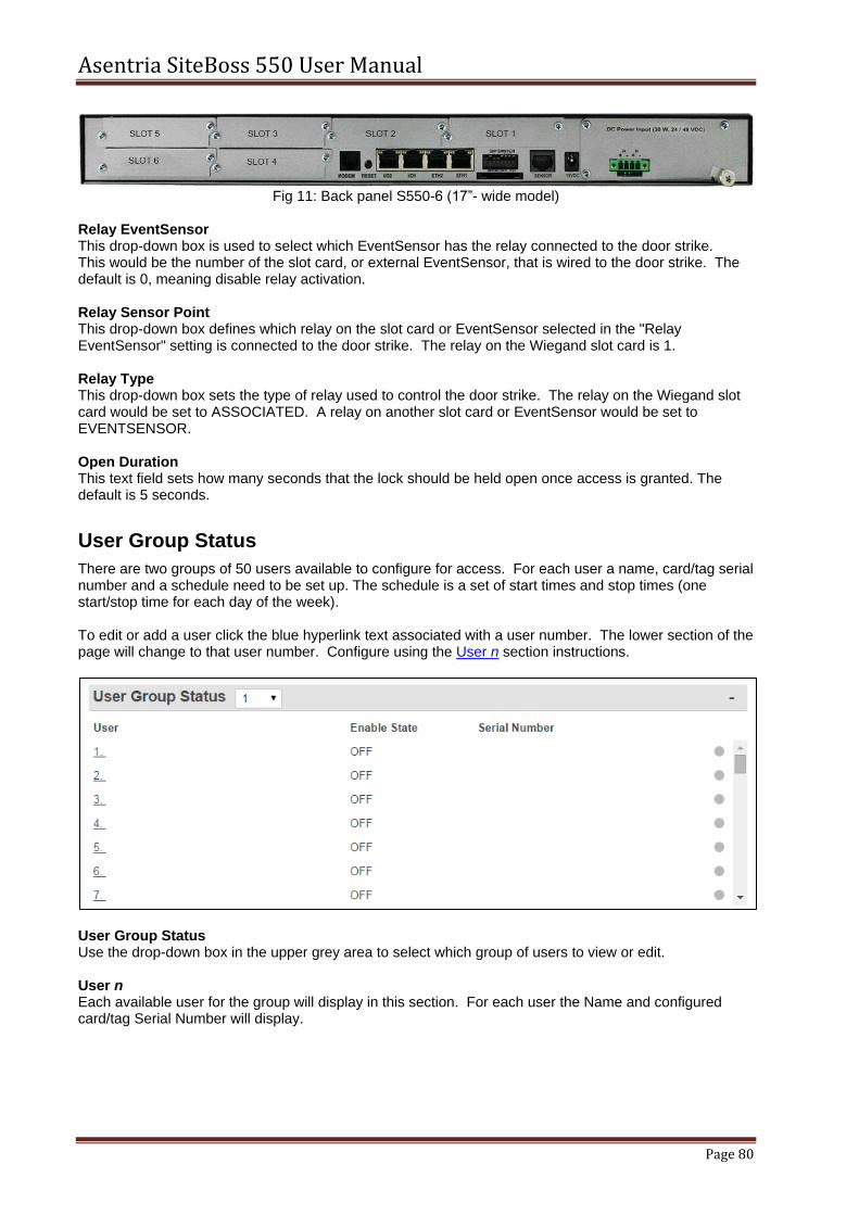
Sensors The Sensor Status page is usually a long page with the status of all internal and external EventSensors. Double click on any grey bar to collapse all sections for easier navigation. A single click will expand or collapse a single section. To configure the settings for any sensor, click the blue text associated with the sensor point and the user will be redirected to the EventSensor configuration page for that EventSensor. Alternately a user can use the menu tree on the left hand side of the screen. Select Events and then the submenu EventSensors. Click the EventSensor in the upper section to reach the configuration page for any specific sensor point.
Asentria SiteBoss 550 User Manual
Page 25
The number of sensors in their alarm state will be displayed at the top of the page. The grey bar will be highlighted red for the section with a sensor in the alarm state and the virtual LED will be lit red.
Show * Sensors The Show drop-down box at the top of the page toggles between ALL and ENABLED sensors. If toggled to ENABLED only the sensors that have been enabled in their configuration page will display. The default is ALL. XML This link will display the page information in XML format. Date/Time The date and time that the SiteBoss is set to are displayed in the upper right corner. The Date and Time can be adjusted in the Settings menu under General, General System.
Power Distribution This menu option will display status on any connected PowerBoss2, PowerBoss4 or PowerBoss6. This status page provides information in real time for the current and voltage of both the Main and individual power outputs.
Main Voltage The Main Voltage displays the voltage across the main power bus bars.
Asentria SiteBoss 550 User Manual
Page 26
Total Current Total Current displays the total current drawn by the PowerBoss and the devices connected to all of the power distribution outputs. Total Power Total Power displays the total power drawn by the PowerBoss and all of the power distribution outputs (Main Voltage x Total Current). Device Current Device Current displays only the current drawn by the PowerBoss itself. Power Output The Power Output section lists installed power distribution outputs showing their Name, State (ON or OFF), and the Current that connected devices are drawing, and, for a PB2, the Fuse status of each (OK or BLOWN).
Power Output Control
To toggle any relay or connected power outputs controlled by your S550, navigate to the Output Control Status display. Click the View Mode button. This will change the mode to Edit. Off and On buttons for Power Outputs or Inactive and Active buttons for relays will display. You will also have Manual and Timer options in the Edit Mode.
Asentria SiteBoss 550 User Manual
Page 27
Manual Output Operation
To manually change the output to the opposite state, click the button corresponding to the desired output(s) and submit.
A challenge pop up will appear at the top of the page, click OK and the relay or power output state will change.
Caution: The power outputs will engage immediately once OK is clicked. Ensure the power line is
clear.
Prudence: Les sorties de puissance s'engageront dès que vous cliquez sur OK. S'assurer que la ligne d'alimentation est clair.
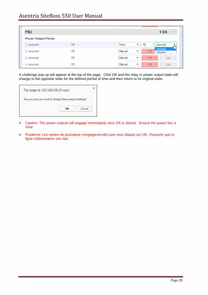
Timer Output Operation
Use the Timer options to select a period of time you want the output(s) to switch from the current state to the opposite state. Once the defined time elapses the output will switch back to its original state. Toggle Manual to Timer and you will get option boxes to define how many seconds or minutes you wish to toggle the power. Manually type in the number of desired seconds or minutes and click Submit at the top of the page.
Asentria SiteBoss 550 User Manual
Page 28
A challenge pop up will appear at the top of the page. Click OK and the relay or power output state will change to the opposite state for the defined period of time and then return to its original state.
Caution: The power outputs will engage immediately once OK is clicked. Ensure the power line is
clear.
Prudence: Les sorties de puissance s'engageront dès que vous cliquez sur OK. S'assurer que la ligne d'alimentation est clair.
Asentria SiteBoss 550 User Manual
Page 29
Settings Menu This section will cover the menu options and settings configurations. This section covers using the Web Interface menu tree and structure. All of these settings can also be controlled via the Command Line Interface. For instructions on controlling your SiteBoss via the Command Line Interface see the Command Line Interface section of this manual.
General
General System The General System page is where you can set the site name, answer string, confirmation prompt, date/time, and other general settings. Sync Date/Time with Computer This is a shortcut key on the top right side of the page to rapidly sync the date and time on the SiteBoss with the Date and Time on the clock of the user's computer. Click button and submit to update the date and time fields.
General
Site Name This is a text field to set the name assigned to the SiteBoss. This name is included with alarm messages (Traps, Emails, etc.) and is displayed at the top of the Web Interface. The name should be unique for clarity. The maximum length is 40 characters. The default setting is “550 - <serial number>”. Answer String This is a text field to set the string that is presented when a user connects to the S550 via the command line interface. The maximum length is 31 characters. The default setting is SiteBoss. Prompt The Prompt option sets the character(s) or settings values displayed as the command line interface prompt. The prompt characters can be customized, and includes the ability to embed one or more settings values in the prompt, for example the site name could be used in the prompt using a settings key of sys.sitename. A customized command prompt can help simplify administration of units, particularly
where multiple units are involved.
Asentria SiteBoss 550 User Manual
Page 30
The Prompt can be set as plain text characters or if using a settings key the syntax is: $(setting_key_name). If the setting key is not accessible for any reason (invalid key, insufficient user access level, etc.), "ERROR" is displayed instead. The setting can contain up to 64 characters, but the prompt itself is limited to 30 characters. The default is >. Confirmation Prompt
This is an ON/OFF toggle to set whether a confirmation prompt (Are you sure (y/n)?) is displayed
when clearing the settings for an EventSensor in the EventSensor Setup menu and certain control functions in the Command Line Interface. The setting will not change without a positive response to the challenge question. The default setting is ON (checked). Space After Date/Time Stamp This is an ON/OFF toggle to set whether a space is appended to the end of the Date/Time stamp. The default setting is ON (checked). Time Stamp Format This is a drop-down box to choose the format for how time stamps are formatted. The options are HH:MM, HH:MM:SS, or BLANK. The default setting is HH:MM. Date Stamp Format This is a drop-down box to choose the option for how date stamps are formatted. The options are MM/DD, MM/DD/YY, MM/DD/YYYY, or BLANK. The default setting is MM/DD. Escape Key This is a text field to set the decimal ASCII character code of the key you must press three times to escape from pass-through or other transparent modes. The default is 27, the <ESC> key. Joinable Pass-through This is a toggle to allow or disallow multiple user pass-through sessions. Checking this checkbox sets the unit to allow more than one concurrent user to connect on a pass-through session. Un-checking this box sets the unit to only allow one concurrent pass-through session, and those attempting to join after the first user is connected will receive a “port in use” error message. The default setting is allow (checked).
Date/Time Section
Note: There is a shortcut button to sync the date and time with the user's computer. Click the button on the top right hand side of the display and submit to update the date and time fields.
Current Date This field is used to set the date. Use the format MM/DD/YY. Current Time This field sets the time, HH:MM:SS, in 24 hour clock format. Note: The date and time settings are maintained by means of an internal battery backup when power
is removed from the S550. GMT Difference Direction Use this field to set whether you are east (AHEAD) or west (BEHIND) of GMT (Greenwich Mean Time). For example, Seattle time is behind (GMT -8), and Tokyo time (GMT +9) is ahead. The default setting is BEHIND. GMT Difference (hours) Use this field to set the number of hours the current time zone is offset from GMT. Valid input ranges from 0 to 12. The default setting is 8 hours. Adjust for Daylight Savings This is an ON/OFF toggle that allows automatic daylight savings time updating.
Asentria SiteBoss 550 User Manual
Page 31
A brief explanation of daylight savings time: On the second Sunday in March, clocks are set ahead one hour at 2:00 a.m. local standard time, which becomes 3:00 a.m. local daylight time. On the first Sunday in November, clocks are set back one hour at 2:00 a.m. local daylight time, which becomes 1:00 a.m. local standard time.
Time Protocol Section
Enable Time Protocol This is a drop-down menu to choose between OFF, SIMPLE, and NTP. The default setting is OFF.
SIMPLE - When network time is set to SIMPLE the unit attempts to contact the configured time servers (see Time Servers setting below) periodically, attempting to query each using Simple Network Time Protocol (SNTP), Time, and Daytime protocols, in that order. Once a response is received for any protocol, the unit sets the system clock to the new time, updates the real time hardware clock (RTC), then the network time process dies. The interval for checking network time is hard-coded to 12 hours plus or minus a random several hours.
NTP - When network time is set to Network Time Protocol (NTP), the NTP daemon is kept running at all times. Unlike the SIMPLE setting, with NTP, the clock is not immediately set as soon as a time server is contacted. Rather, the NTP daemon utilizes various algorithms to set the time in an accurate and robust manner. Since the NTP daemon updates the system time asynchronously, the current time is stored in the RTC every 30 minutes while it is running. Note that if you change the clock manually, it may be a period of an hour or more before NTP resets it.
Time Servers These fields are text fields to set the hostname or IP address of six time-servers. The maximum length is 64 characters. The SiteBoss uses the following servers by default:
time.nist.gov
216.171.120.36
64.90.182.55
Location Tab If a GPS card is installed and active in the unit the Latitude and Longitude fields will populate automatically.
Map in Google This button will take the information from the Locations Settings section and open a tab in Google.com/maps displaying the information on a Google Map of the location. Latitude This is a text field where the Latitude of the unit can be entered. Longitude This is a text field where the Longitude of the unit can be entered.
Asentria SiteBoss 550 User Manual
Page 32
X-Offset, Y-Offset, Angle, Altitude These are additional text fields that can be used to more specifically define the location of the unit.
Networking The Network Settings menu contains all of the options pertaining to network communication.
Network
General
IPv4 Default Router The Default Router option toggles between DYNAMIC and the configured default (Gateway) router address. The default (Gateway) router can be defined by setting the Router Address for Ethernet 1, see the IPv4 section of the Ethernet 1 and 2 chapter for instructions. DYNAMIC simply means that the default router is set only according to the default routing rule of any dynamic network interfaces that may be up, such as the Dialup POTS modem or the Wireless modem. The rule for Dialup POTS modem PPP is that whenever that interface is up, it is always the default route and overrides any other default route. The rule for Wireless modem is that it is the default route when the Wireless default route is enabled. In other words, DYNAMIC default router means the default router will be whatever POTS/Wireless modem PPP decides when it is running. Any other value for the default router means that the default router will be that value (e.g., an Ethernet router). Refer to the IP Routing & Restrictions Feature Guide on the Asentria Product Information Portal for more information. Network Command Processor Duplex This option controls the echo settings for the command interface. Full duplex causes the unit to echo all characters sent to the remote device. Half duplex turns off character echo. The default setting is FULL. Inactivity Timeout The Inactivity Timeout sets the number of minutes (0 - 255) before a network connection with no activity will be terminated. A setting of 0 means an inactive connection will not be terminated. The default setting is 0.
DNS
The Name Resolutions Settings menu can be used to configure the IP Addresses of up to two Domain Name Servers (DNS).
DNS Mode The DNS Mode toggles between MANUAL, ETH1-DHCP, ETH2-DHCP, and DSL. The default setting is MANUAL.
DNS Server 1 and DNS Server 2 The DNS Servers are the IP addresses of Domain Name Servers that you may want to configure so that you can use host names rather than IP addresses in functions where name resolution may be needed, such as; Email server, RTS push hosts, action IP settings, network time servers, scripting TCP connections, etc. The default setting for each DNS Server is 0.0.0.0.
Ethernet Expansion
The Ethernet Expansion settings apply if you have at least one Ethernet Expansion slot card (4E card) installed in the SiteBoss. This feature allows the unit to operate a logical Ethernet interface. The SiteBoss can have up to two Ethernet Expansion slot cards (4E cards) and can potentially operate all available physical Ethernet ports on one logical interface, as if all ports were on a 10-port layer 2 switch. Port Forwarding will need to be configured under Network Settings/Routing Settings/Port Forwarding for traffic to route to connected devices. For more detailed configuration and use instructions please refer to the IP Routing & Restrictions Feature Guide.
IP Address Sets the IPv4 address of the unit reachable by nodes on the network interface consisting of the Ethernet Expansion Card(s). If this is default (0.0.0.0), then each card will still convey Ethernet traffic (acting as Ethernet switch) among its nodes but those nodes will not be able to communicate with the unit. Subnet Mask Sets the IPv4 subnet mask for the Ethernet Expansion network interface. DHCP Starting IP Address Sets the starting IP address for serving DHCP addresses on the Ethernet Expansion network interface. If this is default (0.0.0.0) then the unit will not run DHCP to serve addresses. For DHCP to function the address needs to be on the same subnet as the Ethernet Expansion Card IP. DHCP Lease Time (minutes) Lease time for DHCP clients in minutes (default 60).
Ethernet 1 and 2
The Ethernet Settings section is used to configure each of the two standard Ethernet ports as well as any of the six VLAN interfaces for each port. The drop-down menu in the grey section bar toggles between Ethernet 1 and Ethernet 2 to allow separate configurations for each port. Any installed Ethernet Expansion cards are configured using the Ethernet Expansion menu selections covered in the section above.
General
MAC displays the factory defined MAC address of the Ethernet Port.
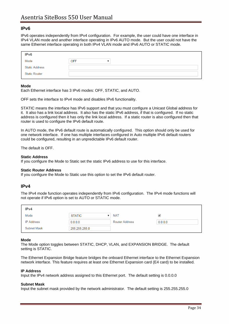
IPv6 operates independently from IPv4 configuration. For example, the user could have one interface in IPv4 VLAN mode and another interface operating in IPv6 AUTO mode. But the user could not have the same Ethernet interface operating in both IPv4 VLAN mode and IPv6 AUTO or STATIC mode.
Mode Each Ethernet interface has 3 IPv6 modes: OFF, STATIC, and AUTO. OFF sets the interface to IPv4 mode and disables IPv6 functionality. STATIC means the interface has IPv6 support and that you must configure a Unicast Global address for it. It also has a link local address. It also has the static IPv6 address, if that is configured. If no static address is configured then it has only the link local address. If a static router is also configured then that router is used to configure the IPv6 default route. In AUTO mode, the IPv6 default route is automatically configured. This option should only be used for one network interface. If one has multiple interfaces configured in Auto multiple IPv6 default routers could be configured, resulting in an unpredictable IPv6 default router. The default is OFF. Static Address If you configure the Mode to Static set the static IPv6 address to use for this interface.
Static Router Address If you configure the Mode to Static use this option to set the IPv6 default router.
IPv4
The IPv4 mode function operates independently from IPv6 configuration. The IPv4 mode functions will not operate if IPv6 option is set to AUTO or STATIC mode.
Mode The Mode option toggles between STATIC, DHCP, VLAN, and EXPANSION BRIDGE. The default setting is STATIC. The Ethernet Expansion Bridge feature bridges the onboard Ethernet interface to the Ethernet Expansion network interface. This feature requires at least one Ethernet Expansion card (E4 card) to be installed. IP Address Input the IPv4 network address assigned to this Ethernet port. The default setting is 0.0.0.0 Subnet Mask Input the subnet mask provided by the network administrator. The default setting is 255.255.255.0
Asentria SiteBoss 550 User Manual
Page 35
Router Address Set the router address provided by the network administrator. The default setting is 0.0.0.0
NAT This is an ON/OFF toggle to enable Network Address Translation. The default setting is ON.
VLAN Settings
If the IPv4 Mode is toggled to VLAN, the VLAN Settings fields are added to the Web Page. Use these fields to configure where any of six individual Virtual Local Area Network (VLAN) connections. The following is a top-level overview of the SiteBoss VLAN settings. Refer to the IP Routing & Restrictions Feature Guide on the Asentria Product Information Portal for a more detailed explanation of VLANs.
ID Input the identifier for the VLAN, 0 to 4094. The default is 0. Priority Set the priority assigned to egress frames, 0 to 7, with 0 being lowest to 7 highest. The default is 0. IP Address Input the IPv4 network address of this VLAN. The default setting is 0.0.0.0 Subnet Mask Input the subnet mask provided by the network administrator. The default setting is 255.255.255.0 Router Address Set the router address provided by the network administrator. The default setting is 0.0.0.0
IP Restrictions
The IP Address Restrictions section allows you to configure permissions and/or restrictions for communications to or from specific IP addresses. IP Address Restriction is the primary defense against unauthorized access via a network or PPP connection. An administrator can restrict access by configuring one or more IP addresses that will be the only ones allowed to access the unit. Restrictions can also be configured to deny access to larger groups of IP addresses using wildcards. IP Address Restrictions do not replace restrictions set by User Profiles, but they do provide an extra level of protection by causing the unit to ignore all network traffic except from the addresses allowed. If no IP restrictions are defined in this menu, all incoming connections are allowed.
The Asentria unit evaluates the list of IP restrictions from top to bottom. When it finds an entry that specifically allows or disallows access, it uses that entry and stops looking. Enter IP restrictions before the allowed addresses or subnets. However, if you enter any restrictions you MUST enter an allowed address or group, or you will lock yourself out. CAUTION: If any access restrictions are configured, a group or IP address that IS allowed access
must be specifically defined. If no authorized access IP address or subnet is specifically defined BEFORE hitting Submit the unit will ignore communications from ALL IP Addresses. Serial access to the command line interface would then be required to regain access to the SiteBoss. See the Access via a Serial Connection section for instructions on how to connect via IO2.
Refer to the IP Routing & Restrictions Feature Guide on the Asentria Product Information Portal for a detailed explanation of IP Address Restrictions. By default, no address restrictions are configured.
The IPv4 wildcards are 0 and 255. .0 is a wildcard that allows access to IP addresses in that group. .255 is a wildcard that denies access to IP addresses in that group. The IPv6 wildcards are :: (double colon) and ffff. :: (double colon) allows IP addresses in that group. ffff restricts IP address in that group. Entering a specific IP address sets that address to be allowed access. There is no way to disallow a specific IP address, only a subnet group. Where n represents a whole number For IPv4
0.0.0.0 sets the unit to allow all IP addresses.
255.255.255.255 restricts all IP addresses.
nnn.nnn.nnn.0 allows all IP addresses in the specified a subnet.
nnn.nnn.nnn.255 restricts all IP addresses the specified in subnet. For IPv6
:: (double colon) allows all IP addresses
nnnn:nnnn:nnnn:nnnn:: allows all IPv6 addresses in a /64 subnet
nnnn:nnnn:nnnn:nnnn:ffff:ffff:ffff:ffff blocks all IPv6 addresses in a /64 subnet
nnnn:nnnn:nnnn:nnnn:nnnn:nnnn:nnnn:nnnn allows a specific IPv6 address
Web Access
This section is used to enable and configure the Web Interface. If you disable the Interface via the Web controls the setting change will not take effect until all control sessions are terminated.
Enable Web Interface This is an ON/OFF toggle to enable or disable the SiteBoss' internal web server. The default setting is ON (checked). Web Session Timeout This field sets the number of minutes (0 to 65535 minutes) a web connection may remain idle before expiring. A setting of 0 means the connection will never automatically expire. The default setting is 30. HTTP Connection Port This option sets the TCP port through which an HTTP connection is made. Set to 0 to prevent access. The default setting is 80. HTTPS Connection Port This option is the TCP port through which an HTTPS connection is made. Set to 0 to prevent access. The default setting is 443. Note: If using SSL, the SSL certificate will show "localhost" as the name, which may cause a
certificate security warning to pop up, depending on the browser being used. The certificate may then be permanently accepted so the warning doesn't appear each time.
SNMP The following is a top-level overview of the various SNMP features and settings. For more detailed configuration and use instructions see the SNMP Operations Feature Guide on the Asentria Product Information Portal or contact Asentria Technical Support.
General
SNMP Agent Enable This is a drop-down box to choose between ALL VERSIONS, V3 ONLY, or OFF, and controls whether the unit responds to SNMP ‘gets’ and ‘sets’ in the selected version. Note that for V3 operation the user profile passwords are used for authentication (via MD5) and encryption (via DES). Passwords for user profiles intended for SNMPv3 use must be at least 8 characters. The default setting is ALL VERSIONS. Note: SNMP Agent Enable does NOT stop SNMP traps from being sent when it is set to OFF.
Security Method This is a drop-down box to choose between MD5-DES and SHA-AES to controls whether MD5 and DES, or SHA-1 and AES, are used for authentication and privacy, respectively, for SNMPv3 get/set/trap operations. The default setting is MD5-DES.
Read / Write / Trap Community These fields set the SNMP trap community names to use. The default setting for all is public. (Maximum length for each is 23 characters) PPP/Trap IP Address Spoofing This specifies what the source IP address field of v1 traps the unit transmits. If undefined then the unit will use the PPP interface address if it leaves the unit on PPP, otherwise it is the first non-0.0.0.0 IP address configured via the Ethernet Settings. Security Name This option is for inputting the authentication name for SNMPv3 operations (maximum Length 31 characters). Security Password This option is for inputting the authentication password for SNMPv3 operations. This field is required to be set to a minimum of 8 characters and 31 characters maximum.
Trap/Notification
These options are used to configure whether to send authentication failure traps and notification settings. Note: SNMP traps are not a guaranteed means of delivering notifications. Traps are a one-way IP
network datagram and the device receiving traps does not acknowledge them. Therefore, if the trap does not reach its intended destination for whatever reason, the sending device has no way of recognizing this and resending the trap. To receive acknowledgments use SNMP Informs, available in SNMPv2 and SNMPv3.
Authentication Failure Traps This is an ON/OFF checkbox to enable the sending of authentication traps. These are notifications of invalid community name usage in SNMP operations. The default setting is OFF (unchecked). Attempts This option sets the number of attempts (1 to 65535) of sending a notification (inform) per cycle (that is, the initial attempt + retries). If this is 0 then the unit will continue attempts infinitely. The default setting is 5. Timeout This field sets the number of seconds (3 to 60) between two attempts to send an SNMP inform in the same cycle. The default setting is 60. Cycles This field sets the maximum number of cycles (0 to 60) to try per notification action, where one notification action corresponds to one "inform" keyword in an action list for an event. A cycle is a set of notification attempts delimited by a successful action delivery or snooze period. The default setting is 10. Snooze Period This option sets the time in minutes (1 to 1440) between two SNMP notification cycles for any one notification action. That is, if you have two events generate informs, each inform will have its own timeouts for retries and cycles, and its own snooze period. The default setting is 60.
Asentria SiteBoss 550 User Manual
Page 39
Security Name / Password When sending SNMPv3 traps, use these options to set the name and password used for authentication when sending SNMPv3 traps (maximum length for each is 31 chars).
Proxy
SNMP Proxy means that the SiteBoss will proxy SNMP PDUs to another agent. In other words, the unit responds to inbound SNMP PDUs on behalf of another agent. This is different from IP routing in that the differentiator is at layer 7 instead of layer 3 or 4; the differentiator is the ingress SNMP OID branch instead of the IP address or UDP port. This facilitates a user to use the unit as the interchange between remote devices via SNMP where routing or port forwarding is not an option. The proxied agent will see the inbound SNMP PDU as SNMP version 1, and it will bear the community that is configured for the proxy entry (not the community that the user uses). The security configuration that the unit uses will be that which agrees with the unit, not with the proxied device. That is, SNMP v1/2c community or SNMPv3 security parameters which the user uses in constructing the SNMP query at their end must agree with the unit, not with the proxied device. Also, the proxied agent will see the PDU arrive from one of the unit's IP addresses, not from the user's IP address.
Proxy This is a drop-down box to configure up to eight proxy entries. Name This is a text field to name the Proxy. Community Use this field to set the community which the device to proxy expects. Agent IP Address Set the IP address of the device to proxy. Ingress OID Branch This is the OID branch to be remapped to egress OID branch to trigger the proxy function. If blank (or the same as the egress OID branch) then the egress OID branch is proxied without remapping. If an ingress OID branch is configured then the ingress OID branch is remapped to the egress OID branch during proxy in order to facilitate proxying multiple like OID branches among multiple devices. Since the ingress OID branch differentiates what device gets proxied, all non-blank ingress OID branches must be unique among each other. Egress OID Branch Use this field to set the Egress OID. This should cover the device to proxy. A blank egress OID branch in the proxy entry disables the proxy entry. A non-blank egress OID branch enables the proxy entry. Agent Port This is the UDP port on which the device to proxy listens. (Not the port on which the unit listens.)
Asentria SiteBoss 550 User Manual
Page 40
SNMP Poll
SNMP Polling is a feature used by an Asentria product to interrogate other SNMP capable devices and to buffer the information received on the SiteBoss. This would limit the need for frequent SNMP interrogation from the NOC and allow continued buffering of data during a site service disruption. For more information refer to the SNMP Operations Feature Guide on the Asentria Product Information Portal or contact Asentria Technical Support.
Mode This is a drop-down menu to choose between OFF, POLL ONLY (just make the results available to view) and POLL BUFFER store the results in the file designated in the next menu option. Store Data To This option toggles through the available file options on the SiteBoss. The default is to FILE1. Store All Period If this field is set to a non-zero value then this time period (in seconds) will poll all configured SNMP Poll requests and buffer all values regardless of threshold.
Poll Request
Up to 64 individual SNMP Polling requests can be configured.
Poll Request This is a drop-down box to bring up the settings fields for any of the 64 individual Polling Requests. Description This field is for entering a user-identifiable description to the SNMP Polling Request. This serves only to more easily identify individual requests on the SiteBoss' menus. The maximum length is 64 characters. Agent IP Address Input the Agent IP address or hostname for this request (maximum Length 64 characters). Read Community Enter the SNMP read community for this request. The default is public (maximum length for each is 32 characters). OID Enter the SNMP object identifier to be polled (maximum Length 64 characters). Period (seconds) This option configures the amount of time between SNMP requests to the agent, measured in seconds. Values are between 1 and 255 (defaults to 10).
Buffer ID A textual field that is part of the record containing the telemetry result. Buffer Threshold This selection controls when new data is stored upon a successful telemetry request. The data stored depends on how the Buffer Threshold field is set: • If the field is left blank then the telemetry is always stored. • If set to "any difference" then the telemetry is stored only if it is different from the last value stored. • If set to an integer (for example: 3) then it is treated as a hysteresis value (the span plus or minus the
last stored value). This means that if the new telemetry does not exceed the threshold (either + or -) beyond the last stored value, then the new telemetry is not stored.
• If set to a floating point number (for example: 3.1) then it is treated as a hysteresis value for SNMP OCTET STRING types where the value looks like a floating point number. This means that if the last stored value is NOT a floating point number then the unit will ignore the threshold and store the new telemetry.
Trap Capture Settings
The SiteBoss can receive, buffer and forward SNMPv1 traps and SNMPv2c inform-requests (informs). Each notification can be subjected to data event evaluation, stored in the Event Log, and delivered via normal Event Log delivery. When SNMP Trap Capture is enabled, the SiteBoss listens on port 162 for notifications. Those over 1024 bytes are ignored. The unit will respond to informs as soon as they arrive regardless of the content of the inform. Refer to the SNMP Operations Feature Guide on the Asentria Product Information Portal for a detailed explanation of SNMP Trap Capture or contact Asentria Technical Support.
Enable This is an ON/OFF checkbox to enable the capturing of SNMPv1 traps and SNMPv2c inform-requests (informs). The default setting is OFF (unchecked). Store Collected Traps In This is a drop-down menu containing all available data files in which the collected traps/informs could be stored. The default setting is FILE1.
Trap Forwarding
These fields can be configured so that the SiteBoss will forward informs and traps to specific target SNMP Manager.
Forwarding Mode This drop-down box toggles between OFF and QUEUE. Off means do not forward. QUEUE will listen for a trap and then resend it to specified targets.
IP Replacement Mode This toggles between NONE, IMPLICIT and EXPLICIT. The Implicit setting will replace the SNMPv1 trap’s agent address field to the ETH1 interface address of the unit. Explicit will replace the field with an explicit address defined in the next field Replacement IP This field is used to set a replacement IP address if you wish to replace the SNMPv1 trap’s agent address field to a specific address in the original trap. The Default setting is 0.0.0.0 Target Host n These fields are used to input the SNMP manager(s) to define where the trap is being forwarded to.
FTP This menu is used to configure automatic FTP pushes of buffered data.
General
FTP Push Enable This is a drop-down menu to choose between OFF, REGULAR, and SECURE. The default setting is OFF. FTP Server Address This field is used to set this field as the IP address or host name of the FTP server to push to (maximum length 64 characters). Passive Mode This is a checkbox to set the FTP Mode as Active or Passive. The default is checked (Passive). SFTP Port Use this option to set the SFTP Port. The default is 22. Permissions This field is used to set the permissions on the pushed file. Permissions are usable for both FTP and SFTP to the extent allowed by the server. If blank then no permissions change is attempted. The default is blank. Account This field is a third login option used only on some FTP servers. Consult your network administrator to see if this is necessary (maximum length 126 characters).
Asentria SiteBoss 550 User Manual
Page 43
Time Between Push Attempts This field sets the number of minutes (1 to 9999) between FTP push attempts. The default setting is 1440 minutes. Directory The Directory is the path used to transfer the file(s). The file(s) is transferred to the root login directory if this option is left blank (maximum length 253 characters). Username / Password These options set the login credentials that are able to access the remote FTP server. The maximum length Username is 126 characters and maximum length Password is 31 characters.
Files to Push
Each available file in the SiteBoss is listed with a checkbox to select which files are to be pushed. The default setting for all is checked (file to be pushed), except for Audit Log, which is unchecked (not pushed).
Remote File Names
These fields are used to configure options where you can give each file a name, other than the default name, and/or prepend a date, time, and unique sequence # to the file name.
Include Date / Time These are ON/OFF checkboxes to enable the addition of the file transfer date and/or time to the beginning of the name of each transferred file of data. The default settings are OFF (unchecked). Include Sequence Numbers This is an ON/OFF checkbox to enable the addition of a unique sequence number to the beginning of the name of each transferred file of data. This ensures that no two transfers will have the same file name. The default setting is OFF. Data File n / Events File These fields are text-entry fields to configure the name each data file will have on the remote server (not including any date, time, or sequence numbers).
Asentria SiteBoss 550 User Manual
Page 44
PPP This menu option is used for configuring settings for the internal dialup, serial, POTs modem. See the Dialup Modem Feature Guide on the Asentria Information Portal for more information.
Dialout
This menu is used to configure settings pertaining to making outbound PPP network connections for a serial dialup POTS modem.
Enabled This is an ON/OFF checkbox to enable PPP dialout. The default setting is OFF (unchecked). Phone Number n These fields set the phone number(s) of the PPP host the S550 is to dial into (maximum length 48 characters each). If the connection fails the SiteBoss will try the next phone numbers entered. IP Address to Suggest This field sets an IP to try to acquire, if defined. The default setting is 0.0.0.0. User Name / Password Use these fields to set the login credentials that are used to log into the PPP host (maximum length for each is 64 characters). Maximum Retries This field defines the maximum number of times to retry a failed connection for all phone numbers present. The default setting is 3. Idle Connection Disconnect (seconds) This field sets the number of seconds to wait before disconnecting an idle connection. A setting of 0 means the unit does not disconnect due to an idle connection. The default setting is 60 seconds. Carrier Detect Timeout (seconds) This field sets the standard login timeouts, from 0 to 65535 seconds. The default setting is 60 seconds. Login Sequence Timeout (seconds) This field sets the standard login timeouts, from 0 to 65535 seconds. The default setting is 30 seconds. Dialout Modem Init String This field sets the modem initialization string (maximum length 48 characters).
This menu is for configuring settings for hosting a PPP connection on the POTs dialup modem.
Enable This is an ON/OFF checkbox to enable inbound PPP connection hosting. The default setting is OFF (unchecked). Idle Connection Disconnect (sec) This field sets the number of seconds (0 to 65535) to wait before disconnecting an idle connection. A setting of 0 means the unit does not disconnect due to an idle connection. The default setting is 60 seconds. Local (Device) IP Address This option sets the IP address of the S550 for the PPP session. The default is 192.168.105.1 Remote (Caller) IP Address This field sets the IP address of the calling device for the PPP session. The default is 192.168.105.2.
Route Test
This menu allows you to configure up to three IP addresses to ping on a regular basis. If any of the configured addresses are up then the unit will assume Ethernet is a reliable way of sending SNMP traps. If all configured addresses are down then the unit will fall back to PPP dialout in order to maintain reliable network connectivity for sending SNMP traps.
Route Test Enable This is an ON/OFF checkbox to enable route testing. The default setting is OFF (unchecked). Duration Between Tests This field sets the number of minutes (0 to 65535) to wait between each round of testing. The default setting is 10 minutes. IP Address n These fields set the hostnames or IP addresses to ping for the test.
Firewall
Asentria SiteBoss 550 User Manual
Page 46
Firewall This is an ON/OFF checkbox to enable or disable the PPP Modem firewall. This should be disabled if attempting to communicate with the unit from an outside device via a PPP connection. The default is ON (checked).
DSL The following describes the menu options for configuring the optional ADSL Modem. For more information regarding the operation of the ADSL modem please refer to the Configuring and Using an Asentria Internal ADSL Modem Feature Guide on the Asentria Product Information Portal or contact Asentria Technical Support.
Start Mode The Start Mode drop-down menu allows a selection between MANUAL and AUTO to set how the DSL interface is to be raised. Set this to MANUAL to require user intervention to raise the DSL interface, or to let a VPN (if it is configured to use DSL) raise the DSL interface when the VPN needs to use DSL. Set this to AUTO to tell the unit to automatically raise the DSL interface upon boot. The default setting is MANUAL. Type Type is a drop-down menu to select between PPPoA, PPPoE, STATIC, or DHCP. This should be set as directed by your ADSL provider. This is the most important DSL setting since its value determines what other DSL settings are applicable to the DSL configuration. The default setting is PPPoA. VPI This option is used to set the VPI (Virtual Path Identifier) used on the DSL interface. This should be set as directed by your ADSL provider and is required for DSL operation. Values are: 0 to 4095. The default setting is 0. VCI This option is used to set the Virtual Channel Identifier for the DSL interface. This should be set as directed by your ADSL provider and is required for DSL operation. Values are: 0 to 65535. The default setting is 0. Encapsulation This is a drop-down menu to select between VCM and LLC to control whether the encapsulation is Virtual Channel Multiplexed or Logical Link Control. This should be set as directed by your ADSL provider and is required for DSL operation. The default setting is VCM. Mode The Mode drop-down box allows a selection between BRIDGED and ROUTED to control whether the DSL is set up for Bridged mode or Routed mode when the DSL type is STATIC. The default setting is BRIDGED.
IP Address This field sets the public IP address of the unit in the case where the DSL link is active. If the DSL type is STATIC, the user needs to set this. If the DSL Type is DHCP, it is set automatically. This should be set as directed by your ADSL provider. The value is a dotted quad IP address and the default setting is 0.0.0.0. Mask Use this field to set the subnet mask used on the DSL interface. If the DSL type is STATIC, the user needs to set this. If the DSL Type if DHCP, it is set automatically. This should be set as directed by your ADSL provider. The value is a dotted quad subnet mask and the default setting is 0.0.0.0. Router Use this option to set the router for the DSL interface. If the DSL type is STATIC, the user needs to set this. If the DSL Type if DHCP, it is set automatically. This should be set as directed by your ADSL provider. Value is a dotted quad IP address and the default setting is 0.0.0.0. Username / Password / Confirm Password Use these options to specify the PPP Username and PPP Password for the DSL interface when the DSL type is set to PPPoA or PPPoE. These should be set as directed by your ADSL provider and are required for DSL operation. These are text strings, maximum length 64 characters.
VPN The following describes the menu options for configuring VPN Settings. A Virtual Private Network (VPN) is a network that is tunneled (the virtual part), typically across a public network, and secured (the private part), typically with IPsec or SSL. There is more information on IPsec and SSL VPNs on the Asentria Product Information Portal or contact Asentria Technical Support.
VPN Settings There are two separate VPN Settings options that can be configured. Select which VPN to configure using the drop-down box in the upper grey area.
General
Mode Mode drop-down box allows a selection between OFF, IPSEC PRIVATE SUBNET, SSL CLIENT, and SSL SERVER to specify the VPN mode. The default setting is OFF. Start Mode The Start Mode toggles between MANUAL, AUTO-PASSIVE and AUTO-ACTIVE. The default is MANUAL.
MANUAL means the user starts the VPN, it does not start automatically.
AUTO-PASSIVE means that the unit listens for a VPN connection when the unit starts.
AUTO-ACTIVE means that the unit starts connecting to a VPN peer when the unit starts. Description This is a user-defined string to server as a description for the tunnel. It has no functional impact. Remote Host This is the IP address of the IPsec peer on the opposite side of the tunnel to which the tunnel is bound.
Public Interface This field sets the public interface to which the unit's side of the tunnel is bound. The drop-down options are ANY, ETH1, ETH2, PPPP, WIRELESS and DSL. The default is ANY.
IPsec
This section is used to configure settings used if Mode is set to IPsec. This section is a basic description of settings and options for an IPsec VPN. For more information refer to the Configuring and Using an IPsec VPN Feature Guide on the Asentria Product Information Portal or contact Asentria Technical Support.
Remote Network This is the subnet on the opposite side of the tunnel relative to the unit. The unit will route traffic destined to this subnet from its private subnet. Private Network This is the subnet on the unit's side of the tunnel. The unit will route traffic designated to this subnet from the remote network. Authentication Type This is a drop-down toggle to select between PSK (preshared key) and RSA (digital signatures). The default is PSK. Authentication RSA Key This is the preshared key in use when Authentication Type = PSK Authentication Preshared Key This is the peer's public key in use when Authentication Type = RSA. Phase 1 Encryption This is the phase 1 (IKE) encryption algorithm to use (must be accommodated by IPsec peer). The drop-down options are 3DES, AES128, and AES 256. The default is 3DES. Phase 1 Hash This is the phase 1 (IKE) hash algorithm to use (must be accommodated by IPsec peer). The drop-down options are MD5 or SHA1. The default is MD5. Phase 1 Life This defines how long, in seconds, before the IKE channel key should be renegotiated. The default is 1800 seconds.
Phase 1 DH Group This is the phase 1 DH group to use (must be accommodated by IPsec peer). The drop-down options are 2 or 5. Phase 2 Encryption This is the phase 2 encryption algorithm to use (must be accommodated by IPsec peer). The drop-down options are 3DES, AES128, and AES 256. The default is 3DES. Phase 2 Hash This is the phase 2 (IKE) hash algorithm to use (must be accommodated by IPsec peer). The drop-down options are MD5, or SHA1. The Default is MD5. Phase 2 Life This defines how long, in seconds, before the tunnel key parameters should be renegotiated. The default is 7200 seconds. Dead Peer Detection Action This controls what should be done when the phase 1 channel detects the peer to be longer present (dead). The drop-down options are HOLD or RESTART. The default is RESTART. Dead Peer Detection Period This defines the period in seconds between keep alive transmissions for dead peer detection. The default is 30 seconds. Dead Peer Detection Timeout This defines how long, in seconds, to wait before disconnecting a connection that has an unacknowledged keep alive or no inbound keep alive. The default is 120 seconds. Compression This is an on/off checkbox that controls whether or not to propose data compression to the peer. The default is checked (ON). PFS This is an on/off checkbox to enable or disabled perfect forward secrecy on the tunnel. The default is checked (ON).
SSL
Use this menu for configuring the settings if the Mode is SSL Client or SSL Server.
Asentria SiteBoss 550 User Manual
Page 50
Protocol This is a drop-down menu to choose between UDP and TCP to set the protocol SSL VPN uses to carry VPN traffic. The default setting is UDP. Port This field is for setting what port (TCP or UDP, as determined by the SSL Protocol) the VPN uses. The default setting is 1194. Username / Password These fields set the username and password that a VPN in SSL CLIENT mode uses when it connects to an OpenVPN server. If the username is blank then the username "u<serial number>" will be used. For example, "u550009999" is the username the unit sends to the OpenVPN server if this setting is blank and the SSL Password setting is not blank. The Username and Password add an extra layer of authentication to fulfill in order for the VPN to connect. Note: the OpenVPN server must be configured appropriately for this. Manual Configuration These fields are used to set up to 16 manual configuration items for OpenVPN, when the VPN mode is either SSL Client or SSL Server. Any configuration items you need which are not automatically handled for you by the unit (such as SSL port, SSL password, certificates, etc.) should be configured here.
Email The Email settings menu is used to configure the SMTP server address, Email domain name and authentication parameters.
General
SMTP Server Hostname/IP Address Enter the hostname or IP address of the outbound mail server (Maximum length 64 characters). Email Domain Name This field is used to sets the Email domain name, e.g. @domain_name.com, which is used when the SiteBoss sends an Email. The default setting is “ASENTRIA.COM” (maximum length 48 characters).
Authentication
These options are used to configure the credentials that may be required by your server for SMTP authentication. Some SMTP servers require an authentication to relay Emails. Authentication Enabled This is an ON/OFF checkbox to enable Email authentication. The default setting is OFF (unchecked).
Asentria SiteBoss 550 User Manual
Page 51
Username / Password / Confirm Password Enter the login credentials as required (maximum length for each is 48 characters).
Routing The following is a top-level overview of the SiteBoss routing settings. For more detailed configuration and use instructions for all of these please refer to the IP Routing & Restrictions Feature Guide on the Asentria Product Information Portal.
General
Ethernet to PPP/Wireless Enable Ethernet to Wireless Settings enable the SiteBoss to forward IP frames originating on Ethernet that are not IP-addressed to the unit as well as forward IP frames received on a wireless interface that are associated with forwarded frames that originated on Ethernet. This is an ON/OFF checkbox to enable Ethernet to PPP/Wireless routing. The default setting is OFF (unchecked). Ethernet to PPP/Wireless NAT Ethernet to PPP/Wireless NAT is an ON/OFF checkbox to enable network address translation on the forwarded frames. Without NAT, a server on PPP would receive a forwarded frame that is IP-addressed according to the network on the Ethernet interface. The default setting is ON (checked). PPP Routing Enable This is an ON/OFF checkbox to enable PPP to Ethernet routing. The default setting is OFF (unchecked). This feature allows forwarding IP frames originating on PPP that are not IP-addressed to the unit, as well as forwarding IP frames received on any Ethernet or VLAN interface that are associated with forwarded frames that originated on PPP. PPP Routing Ethernet Interface This is a drop-down menu to choose between ETH1, ETH2, ETHEXPAN, or any of the six VLAN interfaces on each Ethernet port, to indicate which interface to use for the PPP connection. The default setting is ETH1. Ethernet to WAN Routing Enable The feature allows port ETH2 to operate as a WAN port in the sense that it routes and NATs traffic arriving on ETH1, which is not destined for the unit, out ETH2. This is an ON/OFF checkbox to enable ETH2 to WAN routing. The default setting is OFF (unchecked). Note: Just enabling ETH2 WAN Routing is not enough to route traffic out ETH2. You must also
configure basic network settings for ETH2, as well as the default route or static routes. Configure the default router to be that of ETH2, or configure static routes for specific packet destinations of packets arriving on ETH1 to be routable via ETH2.
Static routes are network routes that specify in a more or less permanent way (static) that traffic to a certain destination (destination host or destination network) gets routed out a certain interface or via a certain gateway. Static routes give you the ability to fine-tune how outbound network traffic leaves the unit for up to eight different routes. You can specify a gateway or interface. If you specify a gateway only then the frame will be IP-addressed to the destination subnet and transmitted to the gateway, and the gateway needs to be either a local Ethernet subnet or the peer of a PPP connection (be it Wireless or Dialup Modem). If you specify an interface, regardless of specifying a gateway, then the frame will be transmitted out that interface.
Note: Specifying that certain traffic goes out a PPP interface does not cause PPP to be raised when that traffic needs to leave the unit. If a PPP interface is down then any static routes that specify a PPP interface are effectively disabled.
Note: Currently there is no support for Dialup Modem PPP and Wireless Modem PPP to be functional at the same time. Eventually this will not be the case, but in the meantime the effect is that if you specify a static route with Wireless Modem PPP interface when the Dialup Modem PPP is up instead of the Wireless, then that traffic will go out the Dialup Modem PPP interface.
Static Route This is a drop-down box to choose which of the eight possible Static Routes to configure. Enable This is an ON/OFF checkbox to enable the static route. The default setting is OFF (unchecked). Interface This is a drop-down menu providing the options from which to select any one of the interfaces available on this SiteBoss – None, Ethernet 1, Ethernet 2, Ethernet 1 VLAN 1, 2, 3, 4, 5, 6, Ethernet 2 VLAN 1, 2, 3, 4, 5, 6, Dialup Modem PPP, and Wireless Modem PPP. The default setting is NONE. You can specify a gateway or interface. If you specify a gateway only, then the frame will be IP-addressed to the destination subnet and transmitted to the gateway, and the gateway needs to be either a local Ethernet subnet or the peer of a PPP connection (be it wireless or PSTN). If you specify an interface, regardless of specifying a gateway, then the frame will be transmitted out that interface. Destination Network Define the destination network notation, i.e., w.x.y.z/s, where s is the significant bits. The default is 0.0.0.0/0. To configure a static host route specify a destination net with the significant bits set to 32. To configure a static network route specify a destination net with the significant bits set to a number less than 32. Gateway Enter the IP address of the gateway. The default setting is 0.0.0.0
Port Forwarding
The Port Forwarding Settings are used for configuring the unit to accept UDP and TCP frames on an interface and route them, translating their IP addresses and UDP/TCP ports according to configuration to a different address on a different interface. Up to 32 individual routes can be
Asentria SiteBoss 550 User Manual
Page 53
configured. See the IP Routing & Restrictions Feature Guide for more additional instructions and examples for the Port Forwarding feature.
Port Forwarding Route The drop-down box in the grey header section is used to choose which route is to be configured. There are 32 available routes. Mode Mode is a drop-down box to choose between OFF, TCP and UDP to select the protocol to be utilized. The default setting is OFF. Destination Address Set the IP address of the destination interface. The default setting is 0.0.0.0. Source Interface This option toggles between NONE, ETH1, ETH2, ETHEXPAN, ETH1 VLAN 1, 2, 3, 4, 5, 6, (E1V1- E1V6), ETH2 VLAN 1, 2, 3, 4, 5, 6, (E2V1-E2V6), Dialup Modem PPP (PPPP), Wireless Modem PPP (WIRELESS), Serial PPP (SPPP), or VPN. The default setting is NONE. Destination Interface The Destination Interface toggles between NONE, ETH1, ETH2, ETHEXPAN, ETH1 VLAN 1, 2, 3, 4, 5, 6, (E1V1- E1V6), ETH2 VLAN 1, 2, 3, 4, 5, 6, (E2V1-E2V6), Dialup Modem PPP (PPPP), Wireless Modem PPP (WIRELESS), Serial PPP (SPPP), or VPN. The default setting is NONE. Source Port Set the port on which the source interface communicates with the unit. Valid values are 0 – 65535. The default setting is 0. Destination Port Set the port on which the unit communicates with the destination interface. Valid values are 0 to 65535. The default setting is 0.
Real-Time Sockets Real-Time Sockets are used to collect data on TCP port 2201 from a serial port in real-time, while buffering data if the network connection goes down. Each file can be configured independently. Refer to the Telnet Feature Guide on the Asentria Product Information Portal for a detailed explanation of Real-Time Sockets or contact Asentria Technical Support.
The File Setup drop-down box is used to select which File is being configured. The default is 1. Mode This is a drop-down box to choose the mode. The options are LISTEN, PUSH, and OFF. When set to LISTEN the option functions like traditional real-time sockets on TCP port 2201. When set to PUSH the unit tries to make a TCP connection on the TCP port specified at Push Port Number. As long as a connection exists, the unit sends all data in the specified file on the connection as data becomes available. The default setting is LISTEN. Show Answer String on Connection This is an ON/OFF checkbox to enable the prompt indicating successful connection to the Real-Time Socket (RTS) port. The default setting is ON (checked). Require XON to Start Data Flow This is an ON/OFF checkbox to enable the Xon/Xoff data flow control requirement. The default setting is OFF (unchecked). Idle Connection Close Timer (Minutes) This field sets the number of minutes (0 – 255) to wait before disconnecting an idle connection. A setting of 0 means the connection will never automatically close. The default setting is 0. Push Hostname/IP Use this field to set the hostname or IP address of the server where the unit will push the data if the Mode is set to PUSH (maximum length is 64 characters). Push Port Number This option sets the TCP-port number that the RTS push should use. The default setting is port 3000. Push Retry Timer This option sets the number of minutes (1 to 255) to wait before retrying an RTS push that has previously failed. The default setting is 5 minutes. Close Socket On Empty File This is an ON/OFF checkbox to set whether or not the SiteBoss will automatically terminate the RTS connection when the file for this port has been emptied. The default setting is OFF (unchecked).
Event Setup
This menu configuration is to handle the Events Log information using the Real-Time Sockets functionality.
Mode This is a drop-down box to choose the mode. The options are LISTEN, PUSH, and OFF. When set to LISTEN the option functions like traditional real-time sockets on TCP port 2201. When set to PUSH the unit tries to make a TCP connection on the TCP port specified at Push Port Number. As long as a connection exists, the unit sends all data in the specified file on the connection as data becomes available. The default setting is LISTEN.
Asentria SiteBoss 550 User Manual
Page 55
Show Answer String On Connection This is an ON/OFF checkbox to enable the prompt indicating successful connection to the Real-Time Socket (RTS) port. The default setting is ON (checked). Require XON to Start Data Flow This is an ON/OFF checkbox to enable the Xon/Xoff data flow control requirement. The default setting is OFF (unchecked). Idle Connection Close Timer (Minutes) This field sets the number of minutes (0 – 255) to wait before disconnecting an idle connection. A setting of 0 means the connection will never automatically close. The default setting is 0. Push Hostname/IP Use this field to set the hostname or IP address of the server where the unit will push the data if the Mode is set to PUSH (maximum length is 64 characters). Close Socket On Empty File This is an ON/OFF checkbox to set whether or not the SiteBoss will automatically terminate the RTS connection when the file for this port has been emptied. The default setting is OFF (unchecked). Push Port Number This option sets the TCP-port number that the RTS push should use. The default setting is port 3000. Push Retry Timer This option sets the number of minutes (1 to 255) to wait before retrying an RTS push that has previously failed. The default setting is 5 minutes.
DNP3 DNP3 is a remote telemetry automation protocol. Devices which support DNP3 are classified mainly as Master Stations or Outstations. A master polls the outstation (mainly for telemetry data) and performs automation tasks on the outstation (such as controlling relays). The outstation services requests from masters and sends (under certain circumstances) unsolicited messages to connected masters. The SiteBoss:
Supports DNP3 as an outstation conveyed via TCP only. Listens for TCP connections on port 20000 (by default). It is not a TCP dual end point; that is, it
does not both listen for and initiate TCP connections to masters. Can support up to 5 concurrent master connections. Conveys sensor telemetry configured in the unit's Telemetry Table. Conforms to DNP3 Level 1 implementation.
Note: DNP3 events (which are elements of the DNP3 protocol) are completely independent of
SiteBoss events (which have associated management and actions). See the DNP3 Feature Guide on the Asentria Information Portal for more information.
The Status Keys, except for Number of Outstation Instances, are all per-outstation status items. Despite the unit supporting multiple concurrent outstations, status keys can show only 1 outstation: these refer to the oldest outstation instance. That is, the outstation with the least recent time started.
General
Number of Outstation Instances This field is a count of running outstation instances. Peer Description This field is a description of the connected peer (the TCP socket endpoint of the master). Start Time This field displays when the outstation instance started.
Error Counters
Any of these items reflecting non-zero values indicates trouble. All these items being zero may indicate that, if any trouble exists, the trouble is not likely found in the processing of DNP3 traffic. These items only increment for as long as the outstation is running.
RX Duplicate Fragments This is a count of duplicate fragments received. RX Colliding Fragments This is a count of colliding fragments received. Solicited Confirms This is a count of solicited response confirmation failures.
Unsolicited Confirms This is a count of unsolicited response confirmation failures. Object Parse Errors This is a count of received data object parse errors. Frame Parse Errors This is a count of received frame parse errors. RX Discarded Frames This is a count of received frames discarded. RX Bad Frame Blocks This is a count of received frame blocks with bad CRC. TX Unsolicited Retries This is a count of retried unsolicited responses. RX Unsupported Frames
Asentria SiteBoss 550 User Manual
Page 57
This is a count of received frames accepted (good CRC and addressed to the outstation) with an unsupported data link function code.
Status Counters
All of these items describe what's happening on the connection to the master on the oldest outstation instance. They don't necessarily indicate trouble.
TX Last Fragment Time of the last fragment transmitted. RX Last Fragment Time of the last fragment received. Events Awaiting Solicited Confirms Number of events reported and awaiting solicited confirmation; usually 0. Events Awaiting Unsolicited Confirms Number of events reported and awaiting unsolicited confirmation; usually 0. TX Cached Responses Count of cached responses transmitted. TX Required Confirms Count of fragments transmitted that required confirmation. TX Solicited Responses Count of solicited responses transmitted. TX Unsolicited Responses Count of unsolicited responses transmitted. RX Solicited Confirms Count of solicited response confirmations received. RX Unsolicited Confirms
Asentria SiteBoss 550 User Manual
Page 58
Count of unsolicited response confirmations received. RX Total Functions Count of total application function codes received. RX Read Functions Count of read application function codes received. RX Direct Operate Functions Count of Direct Operate application function codes received. RX Write Functions Count of write application function codes received. RX Enable Unsolicited Functions Count of enable unsolicited application function codes received. RX Disable Unsolicited Functions Count of disabled unsolicited application function codes received. TX Solicited Objects Count of data objects transmitted in solicited responses. RX Solicited Objects Count of data objects received in solicited requests. Total Events Buffered Number of total events buffered (that is, existing, maybe reported, but not confirmed). Class 1 Events Buffered Portion of the total events buffered that are class 1 events. Class 2 Events Buffered The amount of the total events buffered that are class 2 events. Class 3 Events Buffered The amount of the total events buffered that are class 3 events. TX Last Frame Time Time of the last frame transmitted. RX Last Frame Time Time of the last frame received. TX Frames Total Count of total frames transmitted. RX Accepted Frames Count of total frames accepted. RX Supported Frames Count of total frames accepted with a supported data link function code.
Asentria SiteBoss 550 User Manual
Page 59
Settings
Mode This is a drop-down box to set the Mode to OUTSTATION. The default is OFF. Self Address Support This is an ON/OFF check box to enable self-address support in DNP3. The default is ON (checked). Unsolicited Confirm Timeout This field sets the unsolicited response confirmation timeout in seconds. Setting range is from 1 to 60, with a default at 3 seconds. Enable Unsolicited Reporting This is an ON/OFF checkbox to enable unsolicited response fragments. The default ON (checked). Unsolicited Confirm Retries This field set the number of unsolicited response confirmation retries the SiteBoss will attempt. Setting range is 0 - 10, with the default at 2. Max TX Fragment Size This field sets the maximum size of a transmitted fragment in bytes. Settings range from 249 to 2048, with a default at 2048. Max RX Fragment Size This field sets the maximum size of a received fragment in bytes. Settings range from 249 to 2048, with a default at 2048. Log Filter This is a numeric code to describe what gets logged and it is used for support/troubleshooting analysis only. Keep Alive Timeout This field sets the DNP3 Keep Alive timeout in seconds. Range 0 – 255 and the default is 30 seconds. Setting the Keep Alive to 0 disables the Keep Alive function. Upon expiration the unit initiates a Request Link Status data link transaction.
Outstation
The SiteBoss is an Outstation and expects connections from master(s). The unit expects a master to request operations on objects, and the master may expect the unit to send it autonomous messages (unsolicited responses) to convey important telemetry.
Asentria SiteBoss 550 User Manual
Page 60
DNP3 Address Use this field to set the DNP3 address of the outstation. Setting range from 0 to 65519, with the default set at 1.
TCP Port Use this field to set the TCP port on which to listen for connections. Setting range is 0 - 65534, with the default at 20000.
Master DNP3 Address This field sets the DNP3 address of the intended master upon connection. Setting range is 0 - 65520, with a default at 65520. If set to 0 - 65519 then the outstation discards DNP3 data link frames not from this address. 65520 is not a valid DNP3 address, so, if set to 65520, it means that the outstation will accept frames from any address. Master IP Address This field sets the IP (v4 or v6) address (non-resolved) of the intended master. Default blank. If non-blank then the outstation drops connections from TCP clients not at this address. Master Unsolicited DNP3 Address This field sets the DNP3 destination address of unsolicited responses. Setting range is 0 - 65520, with a default at 65520. If set to 65520, then the outstation addresses data link frames of unsolicited responses to the source address of the last accepted frame received from the master.
Communication
Dialup Modem The following is a top level settings configuration overview for the optional Dialup POTs modem. For additional information see the Dialup Modem Feature Guide on Asentria Product Information Portal or contact Asentria Technical Support. CAUTION – To reduce the risk of fire, use only No. 26 AWG or larger telecommunication line cord.
ATTENTION – Pour réduire les risques d’incendie, utilizer uniquement des conducteurs de
télécommunications 26 AWG au de section supérleure.
General
Data Format This is a drop-down menu to select word length, parity, and stop bit settings. The available options are: 8N1, 7E1, 7O1, and 7N1. The default setting is 8N1. Duplex Duplex sets the echo settings for the modem Command Line Interface. Full duplex causes the SiteBoss to echo all characters sent to the remote device. Half duplex turns off character echo. The default setting is FULL.
Init String This option sets the user-defined modem initialization string. This string is sent to the modem before important factory modem initialization settings, so certain settings in this init string may be overridden. The default setting is ATM1. The Maximum length is 126 characters. Note: Make sure to enter 'AT' at the beginning of this initialization string. Inactivity Timeout This selection sets the number of minutes (0 – 255) to wait before disconnecting an idle modem connection. A setting of 0 means the connection will never automatically expire. The default setting is 0. TAP Init String This option is the user-defined modem initialization string used only when the modem is making an alphanumeric modem callout. Default setting is ATM0. Maximum length is 126 characters Note: Make sure to enter 'AT' at the beginning of this initialization string. TAP Uses 8N1 Data / Parity / Stop This is an ON/OFF checkbox, to force the TAP initialization string data/parity/stop settings to 8N1. The default setting is OFF (unchecked). Upon Modem Connect Go Directly To This drop-down box sets what a user sees directly after connecting via modem. LOGIN requires the user to login with username and password, and will then take them to a command prompt. A serial port (I/O1, I/O2, etc.) redirects a modem user directly to that serial port upon connecting. In this pass-through mode to the serial ports, the command processor of the S550 is transparent. The default setting is LOGIN.
Modem Caller ID Restrictions
Note: Caller ID must be available on the phone line connected to the SiteBoss modem for this feature
to work.
Security Enable This is an ON/OFF toggle to enable caller ID restrictions. When enabled, the SiteBoss will only answer the modem if caller ID indicates one of the allowed phone numbers is connecting. The default setting is OFF. n Select one of these options to add or change a specific phone number. Simple wildcards are allowed in phone numbers: An asterisk (*) wildcard allows for any number of digits to appear to the right of that
Asentria SiteBoss 550 User Manual
Page 62
position. A question mark (?) matches any single digit. If no numbers are defined in this menu, all incoming calls are accepted. The maximum length is 47 characters.
Wireless Modem Below is a brief description of the menu configurations options. For a complete description of the setup and operation of the Wireless Modem, please refer to the Wireless Modem Feature Guide on the Asentria Product Information Portal. Contact Asentria Technical Support for more information. If the optional Wireless Modem expansion card is not installed in the SiteBoss, a basic settings menu will be displayed, but changing any of the settings will not do anything, except for the PPP/Wireless User Name and Password settings.
Status
The upper section of the Wireless Modem Web Page is a Status Page for the Wireless Modem. The information will be filled in based on the type of modem installed. For that reason, the status information section will vary. This section displays information such as if the modem is connected with the wireless network, Signal Strength, the IP Address of the modem along with basic information on the modem itself and any installed SIM.
Mode Mode toggles between SMS ONLY and PERMANENT. SMS ONLY means the modem is only available for out-bound SMS messaging. PERMANENT means the modem maintains an “always on” connection with the network and is available for incoming connections. The default setting is SMS ONLY. Default Route Enable This is an ON/OFF toggle to enable the wireless interface to be the default route when connected. The default setting is OFF (unchecked). For wireless modem connectivity this box needs to be checked. APN This option sets the Access Point Name (APN) as defined by your wireless provider. The maximum length is 31 characters. Firewall This is an ON/OFF toggle to enable or disable the PPP Modem firewall for both PPP Dialout and PPP Hosting. The default is ON (checked). For wireless modem connectivity the firewall will need to be unchecked. PIN Set the PIN associated with the SIM card (if any). The maximum length is 15 characters. PPP Wireless User Name / Password These options set the login credentials for the PPP connection, as needed. The maximum length for each is 64 characters.
Advanced
PPP Debug Enable This is an ON/OFF toggle to enable capturing PPP traffic to a log file which can be extracted from the device and used for debugging purposes. The default setting is OFF (unchecked). Idle Timeout Idle Timeout sets the number of minutes (0 – 255) to wait before disconnecting an inactive modem connection. A setting of 0 means the connection will not be terminated. The default setting is 0 minutes.
Keep-Alive Threshold (minutes) This option sets the length of time, in minutes, after which the wireless modem will send an outbound packet to maintain a connection, if no data has been transmitted. A setting of 0 disables this feature. The default is 0.
Asentria SiteBoss 550 User Manual
Page 64
Connectivity Check
This section is used to configure the SiteBoss to ping up to two user-specified IP addresses at a user-specified interval. If the count of consecutive failed tests reaches a user-specified threshold, and the modem is not in use, the SiteBoss will power cycle the wireless modem. If the situation persists the SiteBoss will power cycle. The modem will not power cycle more often than every 10 minutes. This interval increases on consecutive triggers to a maximum interval of 1 hour. If resetting the modem does not restore connectivity, then the SiteBoss will be power cycled on the next trigger. The SiteBoss will not power cycle more often than every 12 hours. A system message is displayed in any open command processor saying that the system is going to reboot in 30 seconds.
Enable This is an ON/OFF checkbox to enable or disable the feature. The default is OFF (unchecked).
IP Address n Use these fields to set the IP address(es) that will be pinged for the connectivity check. The default is 0.0.0.0. The unit will not ping 0.0.0.0. Check Interval (minutes) This field is used to set how often the IP address(es) will be pinged, in minutes. The range is 1 to 10 minutes. The default is 2. Fail Threshold This field sets how many ping checks in a row must fail before the modem or SiteBoss is power cycled. The range is 2 to 50 and the default is 5.
Serial This Menu is used to configure the two on board serial ports as well as any additional serial ports installed via 4S slot cards.
Command Port
These options apply for Serial I/O 2 when the Port Mode set to Command. I/O 2 is set to Command by default.
Duplex Duplex controls the echo settings for the command line interface. It is a drop-down box to choose between FULL and HALF. Full duplex causes the unit to echo all characters sent to the connected terminal when in COMMAND mode. Half duplex turns off character echo. The default setting is FULL. Inactivity Timeout This option sets the number of minutes (0 - 255) to wait before a serial connection with no activity will be terminated. A setting of 0 means an inactive connection will not be terminated. The default setting is 0.
Asentria SiteBoss 550 User Manual
Page 65
Serial I/O
Serial I/O The drop-down box in the grey menu block area is used to select which installed serial port to configure. The default is I/O 1. Target Name This text field sets the name given to the device connected to the other end of the serial port. This field will accept up to 24 alphanumeric characters. The target name is used in event notifications. The default setting is I/O n. Port Mode Port Mode sets the port function.
• I/O 1 toggles between DATA and AC POWER MONITOR. DATA configures the port as an
inbound RS232 data port. AC POWER MONITOR configures the port to communicate with certain 3
rd party sensors using Modbus RTU. The default setting is DATA.
• I/O 2 toggles between COMMAND, DATA, PPP HOST, and PPP CLIENT. COMMAND allows for
serial command processor access. DATA configures the port as an inbound RS232 data port. PPP HOST and PPP CLIENT configure the port to act as either a host or client in a PPP over serial port connection See the PPP Over Serial Port Feature Guide on the Asentria Information Portal for more information. The default setting is COMMAND.
I/O n all other serial I/O ports added via Serial Port Slot Cards are set to DATA and cannot be changed.
Baud Rate The Baud Rate option is a drop-down box to selection the baud rate for the port. These values range from 300 baud to 115200 baud. The default setting is 19200. Data Format The Data Format is a drop-down box to choose word length, parity, and stop bit settings. The available options are: 8N1, 7E1, 7O1, 7N1, and 8O2. The default setting is 8N1. Handshaking Handshaking drop-down box is used to set how the port will handshake with the connected device. The available options are: NONE, XON/XOFF, BOTH, and DTR. The default setting is NONE.
Data Type The Data Type drop-down box use used to choose the type of data being collected on this port. The options are ASCII and BINARY. The default setting is ASCII. Wrap Around Wrap Around is an ON/OFF checkbox to set whether the incoming data will wrap (overwrite) the oldest data in the file should it become full. The default setting is OFF (unchecked). Date/Time Stamping This is an ON/OFF checkbox to choose if the date and time are prepended to each incoming data string. The default is OFF (unchecked). Site Name Stamping This is and ON/OFF checkbox to choose if the Site Name is prepended to each incoming data string. The default is OFF (unchecked). Character Masking This is an ON/OFF checkbox to enable the character mask. The character mask allows you to block most non-printing ASCII characters. Specifically, the following ASCII character values are blocked: 0, 1, 4-9, 11, 12, 14-31, and 128-255. The default setting is ON (checked). Change ETX to CR/LF This is an ON/OFF checkbox to set whether ETX characters in the incoming data should be converted to CR/LF characters. The default setting is OFF (unchecked). Data Alarm Enable This option is an ON/OFF checkbox to enable data alarm monitoring for this port. The default setting is OFF (unchecked). Store Alarms During Pass-Through This is an ON/OFF checkbox to determine whether data strings that meet data alarm criteria are stored in the Events File when a pass-through session is active on this port. The default setting is OFF (unchecked). Strip Sent Pass-Through LFs This is an ON/OFF checkbox to enable the stripping of linefeeds on pass-through data sent out of the S550. The default setting is OFF Strip Received Pass-Through LFs This is an ON/OFF checkbox to enable the stripping of linefeeds on pass-through data received by the S550. The default setting is OFF (unchecked). Normalize Received Pass-Through EOLs This option is an ON/OFF checkbox to enable the following translations on data received on a serial port and sent to the pass-through client. Some pass-through devices have mixed/inconsistent EOL output; this setting is intended to make it consistent. The default setting is OFF (unchecked).
CR[non-LF]->CRLF[non-LF]
[non-CR][LF]->[non-CR]CRLF
CRLF->CRLF (i.e., no translation of CRLF) Store Data To This selection displays a series of ON/OFF checkboxes to choose whether the data received on this port should be stored. The file number with the same number as the serial port number is set to ON by default and the other available options will be set to OFF (unchecked).
Multiline Record Settings
The SiteBoss has the ability to monitor incoming serial data for multi-line records (individual records that are broken into multiple lines with carriage returns). If the records are separated by a specific number of
Asentria SiteBoss 550 User Manual
Page 67
blank lines, this basic configuration menu will suffice. If a more complex delineation scheme is used, enable Complex Multiline Detection.
Enable This is an ON/OFF checkbox to enable multiline record detection. The default setting is OFF (unchecked). Line Count This option sets the number of blank lines that must come between records. Use this field to set the blank line count if the End Detection is set to BLANKs in the Complex Mode section. The default setting is 0.
Complex Mode
Enable This is an ON/OFF checkbox to enable the advanced multiline detection. The default setting is OFF (unchecked). Start Field n Character Position These fields set the character position used to define the beginning of the multiline field. This option is used with "Count" method record end detection. Start Field n Text These fields set the text used to determine the beginning of the multiline field. This option is used with "Formula" method record end detection. End Field n Character Position This option is the counterpart to start character position option. This option sets the end delimiter for multiline records. This option is used with "Count" method record end detection. End Field n Text This option is the counterpart to start the text option. This option sets the end delimiter for multiline records. This option is used with "Formula" method record end detection. Collect Lines Before Start Record This option sets the number of blank lines that are between each record. End Detection End Detection is a drop-down box to choose between FORMULA, COUNT, and BLANKS to set the method of detecting the end of each record. The default setting is FORMULA.
Asentria SiteBoss 550 User Manual
Page 68
Security The Security Settings menu displays options for setting the security mode, as well as specific and general security settings. See the Securing a SiteBoss Feature Guide on the Asentria Product Information Portal or contact Asentria Technical Support for more information. Note: The "Security Mode" setting controls if the settings under USER PROFILES or RADIUS are in
effect by the SiteBoss. The menu options will be present and can be set regardless of how the function is toggled.
General Security
General
Security Mode This is a drop-down box for choosing between USER PROFILES and RADIUS security settings. If USER PROFILES is selected the fields in the User Profiles menu section we be in use. If RADIUS is selected then the RADIUS menu options will be in effect for accessing your SiteBoss. The default setting is USER PROFILES. Show Username / Password Prompt This is an ON/OFF checkbox to set whether a prompt for logging in is displayed when logging in via the Command Line Interface. The default setting is OFF (unchecked). Globally Allow Access This selection displays options allowing you to toggle ON or OFF access to the SiteBoss via Modem, Telnet (Ports 23, 200x, 210x), FTP, Real-Time Socket, and Secure Shell (SSH). The default setting for all is ON (checked).
General Certificate
The purpose of the Certificate section of the Web UI is to allow a MASTER user to configure SSL certificates used to access the unit via HTTPS. This HTTPS Web UI section allows the MASTER user to create a self-signed certificate, create a certificate signing request (CSR), install an externally signed certificate, and check the status of these 3 things. The benefit is that a user can install a certificate signed (externally) by a certificate authority that is by default trusted by web browsers, thus eliminating the SSL warning in the browser when you browse via HTTPS to the unit.
Common Name This is a Text field to name the unit. The maximum number of characters is 64. The default is siteboss. Organization Unit This is a text field. The maximum number of characters is 40. The default is Technical Services.
Organization This is a text field. The maximum number of characters is 40. The default is Asentria.
Locality This is a text field. The maximum number of characters is 40. The default is Seattle. State/Province This is a text field. The maximum number of characters is 40. The default is Washington. Country This is a text field. The maximum number of characters is 2. The default is US.
Certificate Installation
Choose File Use the functions in the Certificate Signing section of the page to generate a key for your third party certificate authority. Once the CA supplies a certificate key, install the file in the SiteBoss using this button. Once this is done the Install Externally-signed Certificate button will enable. Install Externally-signed Certificate The Install Externally-signed Certificate will be enabled only if user is logged in with MASTER credentials and a file is loaded with your certificate key from your third party certificate authority using the "Choose File" button above it. Click this button to install the certificate. Create Self-signed Certificate The Create Self-signed Certificate button will be enabled only if the user is logged in with MASTER credentials. If the button is clicked the information from the General Cerificate section will populate the read only "Installed Cerificate Information" fields.
Installed Certificate Information
These fields are read only. These read-only items are refreshed in 3 circumstances:
1. Upon initial load. 2. Upon seeing that the user has clicked the "Install Certificate" button.
3. Upon seeing that the user has clicked the "Create Self-signed Certificate" button.
Asentria SiteBoss 550 User Manual
Page 70
Certificate Signing
The Create Certificate Signing Request button is active only if the user is logged in as a MASTER.
Create Certificate Signing Request
Asentria SiteBoss 550 User Manual
Page 71
Clicking this button will generate a Certificate Signing Request Key. This key would then be sent to your selected third party certificate authority. They will use this key to generate a file that is loaded by clicking the Choose File button in the "Certificate Installation" section of the page.
User Profiles When the Security Mode in the General Security section is set to USER PROFILES, this menu is used to set up the User Profile Settings.
Note: By default, the User1 profile is the only one with a preconfigured username and password (admin/password). Usernames and passwords are not pre-configured for Users 2 thru 12. For security reasons it is highly recommended that you change the User 1 password, and record it and all other configured passwords in a secure location.
Profile Status
The top section of the page displays the Enable State, Where the Command Interface Login Goes To and the user Rights status that is configured for all 12 user options. To set up a user click the blue number in the Username column in the Profile Status section and the next lower section of the page will display the options to configure for that profile.
Asentria SiteBoss 550 User Manual
Page 72
Profile n
User Information
Enable This is an ON/OFF checkbox to enable access for this user profile. The default is ON (checked) for User Profile 1 and OFF (unchecked) for all other profiles. User Name This option is used to set the username this profile. Duplicate user names are not allowed. The maximum length is 31 characters. Password / Confirm Password These options are used to set the password for this profile. Maximum length is 31 characters.
Note: Passwords are case sensitive and are masked in all menus and while typing them for security reasons. If a user without permissions accesses the User Profile Settings menus, they will see all fields in this menu either masked or with no data in them.
Expiration This option is used to set a date and/or time that this profile may be automatically disabled. Use the format MM/DD/YYYY HH:MM:SS in 24 hour format. This option is only useable by a Master User on other User Profiles. If left blank the user profile will not expire. User Access Level This setting is a drop-down menu to set this user's access level. The options are MASTER, NONE, VIEW, ADMIN1, ADMIN2, and ADMIN3. See the User Profiles Feature Guide on the Asentria Information Portal for more information on each access level. The default setting is MASTER. Upon Login Start This is a drop-down menu selection to select the starting display option this user will be directed to upon logging in at the Command Line Interface. The options are: COMMAND, PASSTHROUGH and MENU and example displays as shown here: Command
Default Pass-through Port This selection specifies the destination if the “Upon Login Start” action is set to PASSTHROUGH. This is a drop-down menu of all of the available serial ports and CPE devices (1 thru 4). The default setting is Serial Port I/O 1. Upon Pass-through Exit This drop-down box allows a selection of MENU (in the command line interface) or DISCONNECT to set where the user is sent when they exit out of a pass-through connection. PPP Authorization Type This is a drop-down menu option to select between LOCAL, ROUTING and NONE. LOCAL allows PPP access, but denies all routing to whatever LAN the SiteBoss is connected to. ROUTING enables Route Ethernet to PPP and Route PPP to Ethernet for the user, but only if those settings are enabled globally. NONE disables PPP access for the user.
Allowed Connections
These are checkbox ON/OFF options allowing this user access via Local (Console Port), Modem, Telnet, FTP, Real-Time Socket, SSH (Secure Shell), and the Web interface. The default setting for all is ON (checked) for all options.
Asentria SiteBoss 550 User Manual
Page 74
Secure Authentication
General
Console Port Authentication This drop-down menu allows the selection between OFF, and CHALLENGE for Serial Port 2 (I/O2). The default setting is OFF.
OFF allows normal access via the console Port (I/O 2). By default there is no password required for serial access via IO 2. Password access can be enabled by clicking the check box for Local Command in the General section, Requires Password, at the bottom of the User Profiles page on the Web Interface.
CHALLENGE requires the user enter their username/password and then they are prompted with a short challenge code. That code must be plugged into a program called Response Code Generator (RCG). This software can be found on the Documentation and Utilities CD. Contact Asentria Technical Support for this, or download (named “Password Generator”) from the Product Resources page on the Asentria website: http://www.asentria.com/docsandsoftware/productManuals.aspx. RCG requires a shared secret, set in the lower General section on this web page, as well as the challenge code generated by the S550. The user must then respond with the proper hash generated by RCG in order to gain access. For the CHALLENGE setting to function on I/O2 (the Console Port for the S550) the check box for Local Command must be checked in the General section, Requires Password, at the bottom of the User Profiles page on the Web Interface.
Authentication Data Lifetime This setting is used to set the number of minutes (0 – 180) before the single-use password expires. A setting of 0 means the password will never automatically expire. The default setting is 30.
Telnet
Authentication This drop-down menu allows the selection between OFF (normal password mode), CHALLENGE, SEND PASSWORD authentication modes. The default setting is OFF.
OFF authentication requires only the configured username/password authentication. CHALLENGE requires the user enter their username/password and then they are prompted with a short challenge code. That code must be plugged into a program called Response Code Generator (RCG). This software can be found on the Documentation and Utilities CD. Contact Asentria Technical Support for this, or download (named “Password Generator”) from the Product Resources page on the Asentria website: http://www.asentria.com/docsandsoftware/productManuals.aspx. RCG requires a shared secret, set in the lower General Section on this web page, as well as the challenge code generated by the S550. The user must then respond with the proper hash generated by RCG in order to gain access.
SEND PASSWORD will generate a single-use password and send it to the Email address(es) specified by the Authentication Data Sent To field. That password will only allow a login for the user whom it was generated for.
Authentication Data Sent To Use this field to set the Email address where the single-use password is to be sent. This field is used if the Authentication field is set to SEND PASSWORD.
Modem
These Modem settings relate to the internal Dialup POTs modem access only and do not apply for any installed wireless modem. Authentication This drop-down menu will allow a selection between OFF, CHALLENGE, SEND PASSWORD and CALLBACK authentication modes. The default setting is OFF.
OFF authentication requires only the normal username/password authentication.
CHALLENGE requires the user enter their username/password and then they are prompted with a short challenge code. That code must be plugged into a program called Response Code Generator (RCG). This software can be found on the Documentation and Utilities CD. Contact Asentria Technical Support for this, or download (named “Password Generator”) from the Product Resources page on the Asentria website: http://www.asentria.com/docsandsoftware/productManuals.aspx. RCG requires a shared secret, set in the lower General Section on this web page, as well as the challenge code generated by the S550. The user must then respond with the proper hash generated by RCG in order to gain access.
SEND PASSWORD will generate a single-use password and send it to the Email address(es) specified by the Send Password To option. That password will only allow a login for the user whom it was generated for. CALLBACK (via Modem) will cause the S550 to do an immediate callback to the Secure Callback number(s) configured further down in this menu.
Authentication Data Sent To Use this field to set the Email address where the single-use password is to be sent. This field is used if the Authentication field is set to SEND PASSWORD. Callback n These options set the modem callback numbers if the Authentication option is set to CALLBACK. If configured, the S550 will disconnect any modem connections from this user and then attempt to dial out to each of these numbers. If one of the numbers answers, the other end must respond with the login credentials of the user used to initiate the callback (maximum length 48 characters).
Pass-through Permissions
These options are in effect if the “Upon Login Start” action is set to Menu. All available serial ports and CPE devices 1 thru 4 will have and ALLOW or DENY drop-down box option. If a port is set as ALLOW, then that serial port or CPE devices is displayed in the Command Line Interface Menu after the user logs
in. If a port is set as DENY, then that serial port is not displayed in the Menu. The default setting for all ports is ALLOW.
File Release Permissions
All data files, Events Log and Audit Log will have a drop-down box to ALLOW or DENY release permission for this user. The default setting for all is ALLOW.
File Deletion Permissions
These options display a menu showing all data files, Events Log and Audit Log, and toggles ALLOW or DENY Deletion by this user. Default setting for all is ALLOW.
General
The options in this section set parameters for passwords and security that are required for every user who attempts to log into the SiteBoss.
Username and/or Password Required This option toggles between: PASSWORD ONLY, USERNAME/PASSWORD (PW), or PASSWORD(PW)/USERNAME. This field applies when logging onto the Command Line interface via the options selected in the Requires Password section. The default setting is PASSWORD ONLY. Shared / Confirm Secret for Challenge/Response This selection sets the shared secret used to generate Challenge/Response codes. The Maximum length is 48 characters. Challenge/Response requires the use of the free Asentria Response Code Generator program. Contact Asentria Technical Support for this, or download (named “Password Generator”) from the Product Resources page on the Asentria website: http://www.asentria.com/docsandsoftware/productManuals.aspx
This section has ON/OFF check boxes to set whether a password is required when accessing the SiteBoss via the corresponding method. When any of the above options is set to OFF (unchecked), users connecting via that method are automatically granted Master access. By default all options are set to OFF (unchecked) except TCP/IP Port 23 which is set to ON (checked). Note: The Inbound Modem Connection is referring to an internal dialup POTs modem (if installed) and is not applicable to any optional Wireless Modem.
RADIUS Settings If the Security Mode is set to RADIUS in the General Security section then the RADIUS Security Settings configurable in this section will be in use. For a complete description and explanation of RADIUS security, please refer to the RADIUS Security Feature Guide on the Asentria Product Information Portal or contact Asentria Technical Support for more information.
General
Fallback Mode This menu toggles between NONE and USER PROFILES. If the unit gets no response from any RADIUS server when attempting to authenticate a user, no further action is taken if this option is set to NONE. The unit falls back to the User Profiles configuration for authentication if this is set to USER PROFILES. The default setting is NONE. CHAP This is an ON/OFF toggle to set whether the unit uses CHAP (Challenge-Handshake Authentication Protocol) authentication when using RADIUS. ON sets authentication to CHAP. OFF sets authentication to PAP (Password Authentication Protocol). The default setting is OFF. Authentication Port Set the UDP port (1 – 65535) that the RADIUS server uses for authentication/authorization. The default port is 1812. Accounting Port Set the UDP port (1 – 65535) that the RADIUS server uses for accounting traffic. Set to 0 to disable RADIUS accounting. The default port is 1813. Retries This option sets the number of times (1 – 30) the unit should try a RADIUS request again after getting no valid response. Valid meaning a response that is verified as really coming from the RADIUS server. The default setting is 3. Timeout This option sets the number of seconds (1 – 30) the unit waits for a response from the RADIUS server. The default setting is 3 seconds.
Primary / Secondary Server Set the IP Address or host name of the primary and secondary RADIUS server. Primary / Secondary Secret Set the secret for the primary and secondary RADIUS server. The secret is used to authenticate RADIUS network traffic. The maximum length for each is 16 characters.
Access Control The Access Control function keeps a table of access control devices in the unit. The schedule is a set of start times and stop times (one start/stop time for each day of the week for each user). On the current firmware version, up to two devices are supported. There are two groups of 50 users available to configure for access. The only Access Control device interface currently available in the SiteBoss is the Wiegand interface. The Wiegand interface is commonly used to connect a card swipe mechanism to the rest of an electronic entry system. The SiteBoss listens for any transmissions from the Wiegand interface. If the SiteBoss receives a card serial number it is compared to the table, according to the configured user group. If there is a match then the unit activates the door strike relay for the configured delay time and then deactivates it. The unit assumes FAIL SECURE configuration for all door strike relays; in other words, in the absence of any power, doors are locked. For additional information see the Wiegand Card Reader Feature Guide on the Asentria Information portal or contact Asentria Technical Support.
General
The Wiegand ACD runs on units equipped with a Wiegand interface. Each Access Control Device monitors: Access granted Access denied The unit generates an event on these occurrences. It also posts these occurrences to the audit log, if the audit log is enabled. The unit does not post anything to the events log regarding this feature.
Actions This text field is used to set the action(s) the SiteBoss should take upon an access granted or access denied event. The button with the "?" will displays the Actions List which lists the possible actions and the text string format requirements. Refer to Actions List chapter for more information. Class This drop-down menu allows for configuring the severity class for the Sensor Unresponsive event. The available drop-down options will be a list of the classes previously defined using the Class Table menu button. Trap Number This text box sets the Trap Number to be sent with any SNMP traps for this event. The default is 547, but this can be set in the range of 1000 – 1199 as needed.
Device
Device This is a drop-down box to choose which device to configure. On the current firmware version, up to two devices are supported. Enable This is an ON/OFF checkbox to enable management for the selected access control device. The default is OFF (unchecked). Name This text field is used to configure a name of the access control device. This field is for information purpose only and has no effect on the Access Control functionality. The name will be displayed on any configured event messages. The maximum length is 50 characters. Reader This setting allows for selecting the type of Access Control device. Currently the only available option is WIEGAND. User Group This drop-down box is used to select which access group applies to this device. Wiegand EventSensor This drop-down box is used to select which slot card in the SiteBoss is attached to the Wiegand Access Control Device. See the Figure 10 for a picture of how the slots are numbered. An 11" wide S550-2 will only have Slots 1 and 2 available for the Wiegand slot card. The default is 1.
Asentria SiteBoss 550 User Manual
Page 80
Fig 11: Back panel S550-6 (17”- wide model)
Relay EventSensor This drop-down box is used to select which EventSensor has the relay connected to the door strike. This would be the number of the slot card, or external EventSensor, that is wired to the door strike. The default is 0, meaning disable relay activation. Relay Sensor Point This drop-down box defines which relay on the slot card or EventSensor selected in the "Relay EventSensor" setting is connected to the door strike. The relay on the Wiegand slot card is 1. Relay Type This drop-down box sets the type of relay used to control the door strike. The relay on the Wiegand slot card would be set to ASSOCIATED. A relay on another slot card or EventSensor would be set to EVENTSENSOR. Open Duration This text field sets how many seconds that the lock should be held open once access is granted. The default is 5 seconds.
User Group Status
There are two groups of 50 users available to configure for access. For each user a name, card/tag serial number and a schedule need to be set up. The schedule is a set of start times and stop times (one start/stop time for each day of the week). To edit or add a user click the blue hyperlink text associated with a user number. The lower section of the page will change to that user number. Configure using the User n section instructions.
User Group Status Use the drop-down box in the upper grey area to select which group of users to view or edit. User n Each available user for the group will display in this section. For each user the Name and configured card/tag Serial Number will display.
Asentria SiteBoss 550 User Manual
Page 81
User n
Enable This is an ON/OFF checkbox to enable the user. The default is OFF (unchecked). A disabled user is never granted access. Serial Number This text field is the Serial Number of the card associated with the user. Name This is a text field to enter a Name for the user. The maximum length is 50 characters.
Allowed Access Times
The first box for each day of the week sets the time of day (HH:MM) after which this user should be granted access. The second configuration box on the described day is for entering the time of day (HH:MM) after which this user should be forbidden access.
Events
General Events This menu that permits customization of the event message that appears in traps and Emails as well as setting global action parameters.
Clear Event Queue This button deletes any event that has been triggered but the delivery actions have not yet been completed. You will get a "Are you sure you want to clear the event queue?" prompt. Clicking OK will clear any undelivered event messages.
Asentria SiteBoss 550 User Manual
Page 82
Include Date and Time / Site Name / Sensor ID / User Defined Name / Event Class / User Defined State These are each ON/OFF checkboxes that permit customization of the event message that appears in SNMP traps, Emails, SMS messages, pages, etc. sent by the S550. Default setting for each is ON (checked) except for Include Event Class which is OFF (unchecked). Global Actions The Global Actions feature enables an administrator to configure actions that are automatically appended to any other action list when that other action list executes. If all actions for all events on a unit are to be the same then using global actions and trap number means easier management. An action called "NONGLOBAL" can be inserted at the beginning of any event's action list to mean that any global actions and global trap number should not apply to that event. If the NONGLOBAL action is inserted in the action list, it must be inserted first in order to unambiguously tell the unit that actions to process should be excepted from global treatment. This is a text field. See the Actions List or click the large "?" for specific syntax to define the Global Action(s) for the SiteBoss. Global Trap Number This trap number overrides the trap number defined for any other event, even if there are no global actions configured. Setting this value to 0 disables the effect. The default setting is 0. Action Delivery Mode This is a drop-down box to choose between CHRONOLOGICAL or CONCURRENT. The CONCURRENT configures to unit to process multiple event actions immediately, regardless of whether previous actions have been completed or not. CHRONOLOGICAL configures the SiteBoss to process event actions in the order in which they occur, so that one action does not get processed until the previous action is completed. The default is CONCURRENT.
Actions This menu is used to configure a majority of the possible actions that could occur when events are detected.
General
Asentria Alarm Version This drop-down box toggles between 1.0 and 1.1 to indicate which type of Asentria Alarm notification will be displayed. Set this 1.0 for the dialup POTs modem. Set it at 1.1 for TCP when using other delivery methods for your alarm actions. The default setting is 1.1 Require Asentria Alarm ACKs This checkbox is an ON/OFF toggle to enable or disable forcing the unit to require an acknowledgment when first connecting, and after each Asentria Alarm. If disabled, the SiteBoss will allow non-CRC mode where Asentria Alarms are delivered without waiting for any indication that the messages were properly delivered. If enabled, CRC mode is required by the SiteBoss. The default setting is OFF (unchecked). Callout Attempts Use this field to set the total number of times to attempt dispatch, Malert or modem callouts if previous attempts fail. The default setting is 5.
Asentria SiteBoss 550 User Manual
Page 83
Callout Delay This field sets the time in seconds (0 - 400) to wait between callout attempts. The default setting is 60 seconds. Reminder Interval This field sets the time in minutes (0 – 65535) to repeat an action if the sensor (contact closure, temperature, humidity, or voltage) that triggered the alarm is still in the active or alarm state. When the sensor has been returned to the inactive state, the reminder interval is no longer in effect. The default setting is 120 minutes.
Schedule
The Action Schedule Settings menu allows event actions to be limited to defined days and times.
Enable This checkbox is an ON/OFF toggle to enable the action schedule. The default setting is OFF (unchecked). Begin Time / End Time Use these options to set the beginning and ending times (24 hour clock) during which alarm actions can be taken. The default settings are 08:00 (Begin Time) and 17:00 (End Time). These fields are only active if the Action Schedule has been Enabled. Weekdays Only This checkbox is an ON/OFF toggle to set whether actions are only performed Monday thru Friday. The default setting is ON (checked). This option is only active if the Action Schedule has been Enabled.
TCPIP
IP / Host n Use these menu options to configure the IP addresses or Host names to use for easier reference in event actions. The number (1,2,3, etc.) corresponds to the “index” number for Traps and informs as discussed in the Actions List chapter. These can be any relevant server, such as an SNMP management system.
Asentria SiteBoss 550 User Manual
Page 84
Email
Email Address n Use this option to configure Email Addresses to use for easier reference in event actions. These email addresses can also be set to cell phone numbers, using the service provider's SMS gateway address, to allow for SMS alerts to be sent. Ex: [email protected]. The number (1, 2, 3, etc.) corresponds to the “index” number for Email alerts as discussed in the Actions List chapter.
Dialout
Phone Number n Use these fields to set the phone numbers (index 1,2,3,4) to call for each dispatch, malert or modem callout as discussed in the Actions List. These actions can only be used if the optional POTs modem card has been installed.
Pager
This menu is used to configure pager call outs used in event actions. Pager call outs can only be used if an optional POTs dialup modem card is installed in the SiteBoss.
Pager The drop-down box in the Pager section header allows for up to four separate Pager call out configurations. Pager Type This drop-down box toggles between NUMERIC and ALPHA to select the type of pager to call. The default is NUMERIC. Pager Callout Number Use this field to set the phone number for the pager. Pager ID This function is used only with paging systems where many pagers share the same phone number. This is common with alphanumeric pagers. Numeric Message This option is the series of digits (typically callback number) sent to a numeric pager.
Post Callout Delay This field sets the number of seconds the unit will wait before sending the pager ID. The default is 15 seconds. Post ID Delay This field sets the number of seconds the unit will wait before sending any message data. The default is 5 seconds.
Class Table The Class Table is used to set the Class severity levels used for event notifications.
Class n These fields are used to define the severity levels that are assignable to events detected by the SiteBoss. Maximum length is 47 characters. Info, Minor, Major, and Critical are the default class names assigned to the first four classes. These can be changed and others added as desired to meet your specific needs. The class number and name are reported in SNMP traps, Malerts and Talerts. It is a mechanism for you to provide varying severities for different alarms so that you can act on them upon receipt.
Data Alarm/Filters A Data Event is a group of settings configured to generate an alarm when specified characters or alpha/numeric strings are received by the SiteBoss. For more information on Data Alarms see the Configuring and Using Data Events and Alarm Equations Feature Guide on the Asentria Product Information Portal or contact Asentria Technical Support.
General
Data Filter Action The Data Filter Action option toggles between REJECT and ACCEPT to indicate whether data filters are configured to reject or accept specific incoming data string(s). The default setting is REJECT. Note: If no Data Filters are configured, and the Data Filter Action option is toggled to ACCEPT, then
no incoming data will be buffered in any of the files. This field should always be set to REJECT unless there are Data Filters specifically configured for accepting only certain data.
Exit Upon True Data Alarm This is an ON/OFF checkbox to set whether the SiteBoss will stop processing more data event evaluations on a single record after it has found one match. This should be disabled if it is possible to have more than one event in a single record. This is a global setting – it applies to ALL configured data alarms. The default setting is OFF (unchecked).
Field
This section is used to set up to 16 data alarm fields.
Start Use this text box to set the number of the characters to begin a particular alarm field starting from position 1. The Field is disabled if set to 0. The default setting is 0. Length This text box is used to set the length of this particular alarm field. The default setting is 0. Line This text box is used to set the optional line number the field should be limited to in multiline records. Default setting is 0. Type This drop-down box option toggles between Alpha and Numeric. Alpha is used for most alphanumeric data alarming, and Numeric is used if you need to alarm on a range of numbers. The default setting is Alpha. Name This text box is used to define the name the alarm field. This name must be unique, is limited to 12 characters, and it must not contain any spaces. It can contain alphanumeric characters and the underscore, but it must start with a letter. Field names are case sensitive. If left blank, you can refer to the field by its field letter (A, B, etc…).
Asentria SiteBoss 550 User Manual
Page 87
Note: Field names cannot start with $.
Note: Do not start a field with AND or OR.
Macro
Data alarm macros provide a way to define up to 100 equations that can be used in one or more data alarm equations. Each macro consists of an equation and an associated name that can be used to reference the macro in a data alarm equation. They simplify the creating of data alarm events, particularly where more than one event uses the same expression in its equation. Refer to the Configuring and Using Data Events and Alarm Equations Feature Guide on Asentria Product Information Portal or contact Asentria Technical Support for more information.
Name The macro name is the name by which the macro is referenced in any data alarm equation, and can be up to 16 characters in length. Macro names and data field names are not case sensitive. A macro cannot be given the same name as a data field or another macro.
Equation The macro equation is entered the same way as a data alarm equation. A macro equation cannot refer to another macro. The macro equation can be up to 160 characters in length. Note: Macro names cannot start with $.
Note: Do not start a macro name with AND or OR.
Alarm/Filter Overview
Data alarms are configured by selecting an option from the Alarm/Filter Overview section of the page. The grey bar has a drop-down menu to choose a group of options in batches of ten. Select an Alarm/Filter option from 1 to 100 by clicking the blue number hyperlink. The next lower section of the page will display a menu where the settings for that specific Data Alarm can be configured.
Clear The Clear button will clear the counter for the selected data alarm. This happens as soon as this option is selected.
Alarm/Filter
Enable This is an ON/OFF checkbox to enable this data event monitor. The default setting is OFF (unchecked). Mode This drop-down box toggles between ALARM and FILTER to indicate whether the S550 will recognize this data event as an Alarm and take some action, or as a Filter and either accept or reject the data string. The default setting is ALARM. Name This is a text box to set the name for the event monitor. This name is reported with the specified actions. The Maximum length is 16 characters. Equation This text box defines the event equation using the event fields defined in the previous menu. The Maximum length is 160 characters. Refer to the Configuring and Using Data Events and Alarm Equations Feature Guide for a more in-depth explanation of configuring data alarm equations or contact Asentria Technical Support for more information.
Clear On Threshold This is an ON/OFF checkbox to control whether the unit will clear the event counter each time the threshold is reached. If the event counter is allowed to grow beyond the threshold, the unit will not trigger an event again until after the counter is reset. The default setting is ON (checked). Threshold This field sets the number of times the event equation must be matched before an event is triggered. The default setting is 1. Alarm Counter Clear Interval This is a drop-down box to set an interval at which the unit should clear the match counter for an individual data event. The available options are: 2 hours, 4 hours, 6 hours, 8 hours, 12 hours, Daily, and Never. The first clear occurs at midnight. The default setting is 12 Hours. Alarm Counter Reset Time This field is used to set the time at which the daily clear should take place if it is enabled in the Alarm Counter Clear Interval. This value is in 24-hour format. The default setting is 00:00. Actions This text field is used to set the action(s) the SiteBoss should take if the defined Alarm threshold is reached. The button with the "?" will displays the Actions List which lists the possible actions and the text string format requirements. Refer to Actions List chapter for more information. Class This drop-down box is used to set the class for the alarm. The available drop-down options will be a list of the classes previously defined at the Class Table tab. Data Alarm Trap Number This box is used to set the trap number which can be useful when using SNMP trap managers that employ a trap numbering system to help identify incoming traps. The default trap number is 503, but any number in the alternate range of 1000 – 1199 can be used.
EventSensors The S550 supports a wide variety of internal and external sensor devices and relays, including contact closures, temperature and humidity sensors, analog voltage and current sensors, and relays. For the purposes of clarity, all of these will be generally referred to as “EventSensors” (ES) unless a specific type of sensor or relay is being described. If you don't have any internal sensors or relays, or remote ES modules connected, this menu will be unpopulated except for the two internal serial I/O ports shown as “2-CC”. The two serial ports can be configured as contact closures. Because of the numerous ES configurations possible, example menus shown in this section will not look exactly like the ones for your SiteBoss. The example menu below shows EventSensor Settings Status screen for a S550 with the two internal I/O ports and a 4S RS232 Serial Port expansion card in slot 2 (which makes the internal option a 6-CC), an 8V Analog Voltage Input card in slot 3, a Wiegand Access Control card in slot 4, an 8C Contact Closure Card in slot 5, an 8R Relay card in slot 6 and it has a PowerBoss 2 connected to the Sensor port set to slot 9. It also has a Modem slot card in slot 1, which does not display in the EventSensor menus, since it is not a sensor. The S550 supports a maximum of 16 EventSensor slots.
Asentria SiteBoss 550 User Manual
Page 90
To configure the sensor and event settings click the blue text associated with the slot and the lower section of the page will display the event settings for that EventSensor.
EventSensor Name The EventSensor Name is a text field will names the sensor and will display in the upper menu section as well as in traps, e-mails and on the EventSensor Status page. The maximum length is 60 characters. Click any grey bar to configure the settings for the desired EventSensor point. See the EventSensor Configuration Guide on the Asentria Portal for detailed information on configuring different types of EventSensors. If any setting is changed, click the Submit button before navigating away from that sensors setting page option or the changes will not be saved. Depending on the type of EventSensor different settings will display. As an example, a Contact Closure point Event Settings page is displayed.
Enable Sensor The Enable checkbox is an ON/OFF toggle to enable the EventSensor Reporting feature. The default is OFF (unchecked).
Name This test box is a text field to name this contact closure point. The default setting is unnamed. The maximum length is 60 characters.
Alarm State This drop-down box is an OPEN/CLOSED toggle that determines whether an event will be triggered when the contact closure circuit is opened or closed. The default state is CLOSED.
Threshold This text field sets the number of seconds (0-255) that the contact closure must remain in the defined alarm state before the Event State Actions occur.
Normal Threshold This text field sets the number of seconds (0-255) that the contact closure must remain in the normal state before the Return to Normal Actions occur.
Event State / Return to Normal Actions These two fields are text fields to define the actions for the SiteBoss to take in response to the contact closure moving into and/or out of the Alarm state. The button with the "?" will displays the Actions List which lists the possible actions and the text string format requirements. Refer to Actions List chapter for more information.
Trap Number / Normal Trap Number This box is used to set the trap number which can be useful when using SNMP trap managers that employ a trap numbering system to help identify incoming traps. The default trap number is 110, but any number in the alternate range of 1000 – 1199 can be used.
Class / Normal Class The drop-down boxes are used to set the severity class for the alarm. The available drop-down options will be a list of the classes previously defined at the Class Table tab.
Asentria SiteBoss 550 User Manual
Page 92
Alarm Alias / Normal Alias These text fields are used to set customized names that represent the active alarm state or the return to normal state, used when reporting active events for this sensor.
Override Global Reminder Interval This checkbox is an ON/OFF toggle to override the global reminder interval. If this is set to ON a specific reminder interval can be set for this event. The default setting is OFF (unchecked).
Individual Reminder Interval (minutes) This field sets the time in minutes (0 – 65535) for an action to be repeated if the contact closure that triggered the alarm is still in the defined active state. When the sensor has been returned to the inactive state, the reminder interval is no longer in effect. The default setting is 120 minutes.
System Reporting
The System Reporting settings no longer have a functional use.
EventSensor DIP Switch Configuration
The SiteBoss supports a maximum of 16 external EventSensor slots. Some external EventSensors have dip switches on the EventSensor that will need to be set to the slot number you wish that sensor to display at.
1 = DIP Switch up 0 = DIP Switch down
For ESJ style SensorJack sensors, the settings slot will automatically be assigned to it if one is available.
General Sensor Unresponsive Settings
These settings are used to configure the actions the SiteBoss should take if an EventSensor becomes unresponsive.
Asentria SiteBoss 550 User Manual
Page 93
Actions This text field is used to set the action(s) the SiteBoss should take if any EventSensor becomes unresponsive. The button with the "?" will displays the Actions List which lists the possible actions and the text string format requirements. Refer to Actions List chapter for more information. Class This drop-down menu allows for configuring the severity class for the Sensor Unresponsive event. The available drop-down options will be a list of the classes previously defined using the Class Table menu button. Trap Number This text box sets the Trap Number to be sent with any SNMP traps for this event. The default is 50, but this can be set in the range of 1000 – 1199 as needed. Timeout This field defines the time (10 - 65535 seconds) to wait before declaring a non-communicative EventSensor unresponsive. The default setting is 30 seconds.
EventSensor Reporting Settings
EventSensor Reporting is a feature that allows an EventSensor connected to one Asentria product to transmit data to another Asentria product via a TCP connection. This feature does not need to be enabled in order to allow for normal alarm notice delivery. For a further explanation of EventSensor Reporting, refer to the Event Sensor Reporting Feature Guide on the Asentria Information Portal or contact Asentria Technical Support.
The client unit is the SiteBoss with the sensor physically connected to it. The host unit is the SiteBoss to whom the client unit will report when there is a change in the status of its sensor. Enable Reporting Host This is an ON/OFF checkbox to enable this S550 to be a host for EventSensor reporting from another Asentria device. The default is OFF (unchecked). Reporting Host Port This is used to set the TCP Port that this SiteBoss will use for receiving sensor reports from another Asentria device. The default is 4000. Report To IP Use this field to set the IP address of the host SiteBoss a sensor connected to this SiteBoss would report to. Report To Port This option sets the TCP port that a sensor connected to this SiteBoss would use to report to another host SiteBoss. The default is 4000.
Fuel Sensors Up to three different Fuel Sensors can be configured. Refer to the Fuel Sensor Feature Guide for a more in-depth explanation of configuring fuel sensing.
Select which of three possible fuel sensors you are configuring using the drop-down button at the top of the Fuel Sensor Settings page.
General
Enable This is a checkbox to enable fuel sensor events. The default value is OFF (unchecked). Sensor Type This is a drop-down box containing the options of CURRENT, RESISTIVE FLOAT and VOLTAGE to indicate the type of fuel sensor being used. The default value is CURRENT. Name The Name option is an alphanumeric field that allows you to name this fuel sensor (maximum length is 60 characters). The default setting is ‘unnamed’.
Level
This section of the page is used to configure the fuel level measurement settings.
Distance Unit This is a drop-down box to toggle between INCH and CM. This specifies the distance unit to be used when setting the tank dimension. The default value is CM. Analog Input EventSensor This field sets the slot number of the EventSensor associated with this fuel sensor. Allowed values are 200 (for Internal EventSensor) or 1 – 16. The default value is 200. Analog Input Point This field sets the input point on the EventSensor that is associated with this fuel sensor. Range is 1-48. The default value is 1. Raw Value Top This field sets the analog input reading that corresponds to the SENSOR FULL point. This is an integer with range of 0 to 2,147,483,647. The default value is 5000.
Top Offset The Top Offset defines the distance, in the specified distance unit, between the SENSOR FULL point and the TANK FULL point. This is a floating-point value with range of -1,000 to +1,000. A positive value means the SENSOR FULL point is above the TANK FULL point, and a negative value means it is below. The default value is 0.0. Raw Value Bottom This field sets the analog input reading that corresponds to the minimum fluid height measurable by the fuel sensor. This is an integer with range of 0 to 2,147,483,647. The default value is 0. Bottom Offset The Bottom Offset defines the distance, in the specified distance unit, between the SENSOR EMPTY point and the TANK EMPTY point. This is a floating-point value with range of -1,000 to +1,000. A positive value means the SENSOR EMPTY point is above the TANK EMPTY point and a negative value means it is below the TANK EMPTY point. The default value is 0.0.
Volume
The Volume section of the page is used to configure the prerequisite dimensional measurements that apply the fuel tank.
Shape The Shape drop-down box allows the selection between LINEAR, HORIZ CYL, VERT OVAL and CUSTOM to set the shape of the fuel tank. The default value is LINEAR. Height This field sets the height of the tank, from the TANK EMPTY point to the TANK FULL point, in the specified distance unit. This is a floating-point value with range of 0.0 to 1000. The default value is 100. Dimension A This field sets tank dimension measurement "A" for certain tank profiles, in the specified distance unit. For VERT OVAL this is the horizontal length of the tank. This is a floating-point value with range of 0.0 to 1000. The default value is 0.0.
Asentria SiteBoss 550 User Manual
Page 96
Tank Dimension B This field sets tank dimension measurement "B" for certain tank profiles, in the specified distance unit. For VERT OVAL this is the width of the tank. This is a floating-point value with range of 0.0 to 1000. The default value is 0.0. Tank Volume This field sets the number of volume units the tank contains when full. Range is 0 to 2,147,483,647. The default value is 200.0. Volume Unit This field sets the name of the unit representing fluid volume in the tank. This is only used for display purposes and it does not affect the volume calculation in any way. The default value is "Liters”. Input Filter Averaging This option sets the number of samples used to filter the analog input value that is used for the tank volume calculation. The filtering is applied after the adjusted raw value. Range is 1 to 300; default is 1 (no filtering). Custom Tank When CUSTOM is selected for tank Shape, the system uses user-provided data to calculate the volume of fluid in the tank. The data is entered into a table of height/volume pairs, where a fluid height and corresponding tank volume are entered. Up to 32 height/volume pairs can be entered.
Event
This section of the page is used for configuring alarm notifications based on changes in the fuel level.
Event Enable This is an ON/OFF checkbox to enable Volume Events. The default setting is OFF (unchecked). Deadband The Deadband sets a range (in volume units) on either side of a fuel volume setting that prevents the event from repeatedly going in and out of the alarm state as the actual fuel volume fluctuates above and below the setting. The default value is 6.0. Very High / High / Low / Very Low Volume These fields set the fuel volume (in volume units) threshold at which the Event Action(s) will be triggered. Very High / High / Return to Normal / Low / Very Low Actions These text fields are used to set the action(s) that will be triggered once the fuel level crosses the defined threshold. The button with the "?" will displays the Actions List which lists the possible actions and the text string format requirements. Refer to Actions List chapter for more information.
Asentria SiteBoss 550 User Manual
Page 97
Very High / High / Return to Normal / Low / Very Low Trap Number Use this text field to set the trap number which can be useful when using SNMP trap managers that employ a trap numbering system to help identify incoming traps. The default trap number for all fuel volume events is 519, but any number in the alternate range of 1000 – 1199 can be used. Very High / High / Return to Normal / Low / Very Low Class Use this drop-down box to set the severity class for the event. When these drop-down options are selected, a list of the classes previously defined via the Class Table button is displayed. The default for all is Info.
Disconnect
This section of the page is for configuring alarm notifications of the fuel sensor being disconnected.
Enabled This is an ON/OFF checkbox to enable Volume Events. The default setting is OFF (unchecked). High / Low Value These menu options are used to set the High end and low end of normal for the analog input associated with the fuel sensor. If the input value falls outside the delineated range, then the sensor is considered "disconnected". If both high and low values are set to 0 (the default value), then the sensor will always be considered "connected". Actions This text field is used to set the action(s) that will be triggered if the fuel level sensor is disconnected. The button with the "?" will displays the Actions List which lists the possible actions and the text string format requirements. Refer to Actions List chapter for more information. Normal Actions This option is used to set the action(s) that will be triggered once the fuel sensor is no longer disconnected. The button with the "?" will displays the Actions List which lists the possible actions and the text string format requirements. Refer to Actions List chapter for more information. Event Trap Number This option is used to set the trap number which can be useful when using SNMP trap managers that employ a trap numbering system to help identify incoming traps. The default trap number for disconnect events is 515, but any number in the alternate range of 1000 – 1199 can be used. Normal Trap Number This option is used to set the trap number which can be useful when using SNMP trap managers that employ a trap numbering system to help identify incoming traps. The default trap number is 515, but any number in the alternate range of 1000 – 1199 can be used. Class Use this drop-down box to set the severity class for the event. When these drop-down options are selected, a list of the classes previously defined via the Class Table button is displayed. The default is Info.
Asentria SiteBoss 550 User Manual
Page 98
Normal Class Use this drop-down box to set the severity class for the event. When these drop-down options are selected, a list of the classes previously defined via the Class Table button is displayed. The default is Info.
Reporting
These Reporting functions no longer have a use within the system.
Change Events
The Slow Change and Sudden Change Event settings are used to trigger an event if the change in volume in the fuel level readings moves out of configured settings.
Enable These are ON/OFF checkboxes used to enable the Change Event. The default values are OFF. Time This field is used to define a time window that would trigger the Change Event. For a Sudden Change Event the time is measured in minutes. The default is 10 minutes. For a Slow Change the time is measured in hours and the default is 6 hours. Amplitude (volume units) The Amplitude is the amount of change, in volume units, that triggers an event. Actions These options set the action(s) that will be triggered if there is a sudden or slow change in the fuel level readings. The button with the "?" will displays the Actions List which lists the possible actions and the text string format requirements. Refer to Actions List chapter for more information. Trap Number These options are for setting the trap number which can be useful when using SNMP trap managers that employ a trap numbering system to help identify incoming traps. The default trap number for a Sudden Change event is 527 and for a Slow Change the trap number is 528. Any number in the alternate range of 1000 – 1199 can be used. Class These options are for setting the severity class for the event. Use the drop-down box to select one of the classes that are defined in the Class Table settings menu. The default value is Info for both Slow and Sudden Change Events.
Asentria SiteBoss 550 User Manual
Page 99
No-Data Alarms No-Data Alarms can be configured on the SiteBoss to monitor data coming in via the serial ports, and take an alarm action if a certain period of time passes with no data. These menu options allow you to configure two separate No-Data Alarms, each of which can be configured for two different ranges of times with different time durations. The periods of time should be configured to match the calling patterns of your business or organization. For example, if your normal business hours are M-F 8:00 to 5:00, you will want to set lower time durations during those hours than you would “after hours” when call volumes are lighter and the periods of time where there is "no data“ might be longer.
No-Data Alarm Settings The drop-down menu in the upper grey section allows the selection between the two possible No-Data alarm options. Enable This check box is an ON/OFF toggle to enable the no-data monitor. The default setting is OFF (unchecked). Message This field is a text box to configure a message that is delivered with this event alarm message. The default setting is "No-Data Timeout n“. The maximum length is 126 characters. Actions This option sets the action(s) that will be triggered if there is no data on the selected serial ports. The button with the "?" will displays the Actions List which lists the possible actions and the text string format requirements. Refer to Actions List chapter for more information. Class This option is for setting the severity class for the event. Use the drop-down box to select one of the classes that are defined in the Class Table settings menu. The default value is Info. Trap Number This field is used to set the number to be sent with any SNMP traps for this event. The Trap numbers are helpful when using SNMP trap managers that employ a trap numbering system to help identify incoming traps. The default is 505, but trap number can also be set in the range of 1000 – 1199 as needed.
Asentria SiteBoss 550 User Manual
Page 100
Apply Alarm on Days This is a text box to define the days of the week this alarm applies to. The days can be abbreviated Su for Sunday, M for Monday, Tu for Tuesday, W for Wednesday, Th for Thursday, F for Friday and Sa for Saturday. The default setting is Monday thru Friday (MTuWThF). Exclusion List This field is used to specify specific dates when this No-Data Alarm should “take the day off”. For example, Christmas is a day you might want to add here. The entries should be entered as MM/DD followed by a space for each entry. For an example excluding Christmas and New Year's Day would look like this:
No dates are excluded by default. Begin Time / End Time These fields are to set the beginning and ending times (24 hour clock) for each of two ranges of time. Duration in minutes These fields set the number of minutes (0-65535) that the SiteBoss should wait without receiving data before executing the specified Actions. Alarm Application The checkbox options are used to toggle ON or OFF the installed serial ports to designate whether this particular No-Data Alarm is active on that Serial Port. The default setting is OFF (unchecked) for all ports.
Scheduled Events Scheduled Events allow you to schedule a specific date/time for an alarm action to occur. For example, you might want the S550 to send you an Email every morning at 8:00 just so you know it is live on the network.
Scheduled Event Settings The drop-down box in the upper grey area allows you to configure two separate Scheduled Events, each of which can be configured for any one time on any day of the week. Each day’s time can be scheduled independently from the others. Enable This checkbox is an ON/OFF toggle to enable the Scheduled Event. The default setting is OFF (unchecked).
Asentria SiteBoss 550 User Manual
Page 101
Actions This text box option is used to set the action(s) that the SiteBoss will take on the scheduled days and times. The button with the "?" will displays the Actions List which lists the possible actions and the text string format requirements. Refer to Actions List chapter for more information. Message This text box sets the text string to be delivered with this event message. The default setting is "Scheduled Event n“. The maximum length is 126 characters. Event Class This option is for setting the severity class for the event. Use the drop-down box to select one of the classes that are defined in the Class Table settings menu. The default value is Info. Trap Number This field is used to set the number to be sent with any SNMP traps for this event. The Trap numbers are helpful when using SNMP trap managers that employ a trap numbering system to help identify incoming traps. The default is 506, but trap number can also be set in the range of 1000 – 1199 as needed. (Day) Event Time These fields set the time each day for the scheduled event action to occur. The time should be entered in HH:MM in 24 hour clock format. No times are entered by default for any day. Exclusion List This field is used to specify specific dates when the scheduled event should “take the day off”. For example, Christmas is a day you might want to add here. The entries should be entered as MM/DD followed by a space for each entry. For example excluding Christmas and New Year's Day:
No dates are excluded by default.
Serial Handshaking Serial Handshaking Alarms allows the SiteBoss to monitor each of its serial ports and alert you if the Data Terminal Ready (DTR) signal from the connected device drops low. This would be an indicator that the connected device has failed, or the cable between the SiteBoss and the device has been disconnected, or a number of other reasons depending on the device. It can also alert you when the DTR signal goes high again.
Serial Handshaking Alarms Settings The drop-down box in the upper grey section of the page allows for the selection to configure the Serial Handshaking Alarms for any installed Serial Port.
Asentria SiteBoss 550 User Manual
Page 102
Enable The Low Alarm and High Alarm Enable check boxes are ON/OFF toggles to enable alarming on high or low handshaking levels. The default settings are OFF (unchecked). Actions The Actions text boxes are used to set the action(s) that the SiteBoss will take if the DTR signal drops low or returns to the higher level. The button with the "?" will displays the Actions List which lists the possible actions and the text string format requirements. Refer to Actions List chapter for more information. Class These options are for setting the severity class for the event. Use the drop-down box to select one of the classes that are defined in the Class Table settings menu. The default values are Info. Trap Number These fields are used to set the number to be sent with any SNMP traps for the event. The Trap numbers are helpful when using SNMP trap managers that employ a trap numbering system to help identify incoming traps. The defaults are 510, but trap number can also be set in the range of 1000 – 1199 as needed. Message The Message fields are used to set the message sent with any text-based action for this event. The default settings are “Handshake Low" and “Handshake High”. The maximum length for each is 126 characters.
Reset Event The Reset Event Settings are used to configure event actions to be performed after the unit has been restarted. These actions would be executed regardless of whether the unit was reset via a restart command or by power cycling.
Enable Event This checkbox is an ON/OFF toggle to enable the Reset Event. The default setting is OFF (unchecked). Event Actions This text box option is used to set the action(s) that the SiteBoss will take on if it is restarted. The button with the "?" will displays the Actions List which lists the possible actions and the text string format requirements. Refer to Actions List chapter for more information. Event Class This option is for setting the severity class for the event. Use the drop-down box to select one of the classes that are defined in the Class Table settings menu. The default value is Info. Event Trap Number This field is used to set the number to be sent with any SNMP traps for this event. The Trap numbers are helpful when using SNMP trap managers that employ a trap numbering system to help identify incoming traps. The default is 543, but trap number can also be set in the range of 1000 – 1199 as needed.
Asentria SiteBoss 550 User Manual
Page 103
Delay After Reset (seconds) Enter the number of seconds for the SiteBoss to wait after unit finishes booting before executing the Event Action(s) that have been set for this event. The default is 0 and the maximum is 3600 (1 hour). Event Message This text box is used to configure a text string to be delivered with this event message. The default setting is "Reset Event". The maximum length is 80 characters.
Telemetry The telemetry table is a table of things to monitor on the unit for which telemetry is made available to other features on the same unit such as DNP3. DNP3 motivated the initial contents of the table, but it also has content for other non-DNP3 functionality. The entire telemetry table is configured via Settings Keys. Each row in the table is called a point. The SiteBoss supports 256 telemetry points.
All telemetry table settings are located in the event.point setting key branch. Each row in the table is a
"point". This point nomenclature is inherited from the DNP3 point definition where a point is an "instance of a point type". A point type is a "classification for entities having a common set of characteristics and attributes. Examples include binary inputs, analog inputs ...." Asentria adds other metadata to the point entity to support other non-DNP3 telemetry management methods.
Auto-Configure This button automatically populates the unit's Telemetry Table with all EventSensors (not including Fuel or AC Power Monitor sensors).
Note: When configuring the telemetry table, manually configure DNP3 Deadbands appropriate to the sensor telemetry.
The drop-down box in the upper Telemetry Settings section is a toggle the Auto-Configure function to Enabled Sensors only or All Sensors.
Asentria SiteBoss 550 User Manual
Page 104
This function will not work unless the DNP3 Network Settings are toggled to OUTSTATION.
Telemetry Overview
The drop-down box allows toggling the displayed telemetry points from 1 to 256. To manually configure settings for a specific point click the blue text in the "Name" column and the lower section will display setting options for that point.
Telemetry Point n
DNP3 identifies telemetry via points, which are entities that have characteristics like index, name, type, deadband, and class. Any telemetry is uniquely identified in DNP3 via its index and type. Index is a number the SiteBoss uses the row number of the Telemetry Table.
Name This text box is used to name the Telemetry point. The maximum length is 60 characters. Key Use this field to set the Settings Key name of telemetry to monitor. Typically, this key name is for an EventSensor value, but most keys on the unit can be used here including scripting variable keys. Servicing telemetry for a point requires this setting be configured. Type This drop-down box is used to set the DNP3 point type. The SiteBoss supports three of the 5 DNP3 point types. Available options are: BINARY INPUT (contact closure), ANALOG INPUT, and BINARY OUTPUT (relay or power output). By default a point has no type (NONE). Servicing telemetry for a point requires this setting configured. Class DNP3 point class (0, 1, 2, 3, or NONE). Point classes govern from which points DNP3 events can be generated. DNP3 events can be packed in DNP3 Unsolicited Responses, which are analogous to autonomous (instead of polled) telemetry reporting. This is analogous to SNMP Trap vs SNMP Get. Servicing DNP3 unsolicited reporting for a point requires this setting configured to 1, 2, or 3. Deadband This field sets the value by which the telemetry value must change in order for a DNP3 event to be generated, if the point class is 1, 2, or 3. The deadband is default blank (meaning no deadband, or a deadband of essentially 0 for ANALOG INPUT point types. Regardless of how the configure the telemetry table (manually or via DNP3 auto-configure), you should configure an appropriate deadband for each point. Short Code This field is reserved for future use.
Asentria SiteBoss 550 User Manual
Page 105
Device Management
Job Scheduling The SiteBoss can be configured for starting up to 8 jobs scheduled to run automatically. These schedules include start dates and times, and settings for repeating those schedules on a daily, weekly, monthly, or yearly basis. The Schedule Number is used when configuring Generator Exercising functions in the Exercising menu. It can also be used with LUA Scripts to configure SiteBoss actions on a regular schedule. The upper section of the page shows the general Status of any configured schedules. Once a schedule has been configured, the Enabled Status will show "ON" and the "LED" on the right hand side of the display will turn from grey to green. The Upcoming Schedule shows the next time this schedule is configured to start its assigned actions. Note: During a scheduled relay event, such as generator exercising, insure the S550 remains
powered on during the entire time the relay is in the Active state. Do not power the unit off, press the external Reset button, press the Restart button on the System Administration page, or perform a software update while any relay is in the Active state. Following any of those actions, an Active relay will remain Active after the unit reboots regardless of any configured schedule. For generator exercising, this means the generator will continue to run indefinitely beyond the scheduled exercise period.
Select the job to configure by clicking the blue "view" text in the upper section of the screen. This will display its settings in the lower portion of the screen.
Enable This checkbox is an ON/OFF toggle to turn on this particular Job Schedule. The default setting is OFF (unchecked). Repeat Mode This is a drop-down box is used to select the specific sub-menu with options to set the repetition of the Job Schedule. The five options for how often the Job Schedule is to be repeated are NONE, DAILY, WEEKLY, MONTHLY and YEARLY. Each option displays different configuration options for your schedule. The default is NONE.
Asentria SiteBoss 550 User Manual
Page 106
Start This test box sets the date (mm/dd/yyyy) and time in 24 hour clock format (hh:mm:ss) that controls the date and time this schedule starts.
Repeat Mode – DAILY
Setting the Repeat Mode drop-down box to DAILY will allow the user to schedule the job to run once during a 24 hour period and then have that job repeated some number of days later at that same time of day. Additional options are provided for when the repeat mode for this Job Schedule will end.
Repetition Settings
Repeat Every Use this field to set how many days should pass before the job repeats. This option will set the job to repeat after that many days. If set to 1 then it will repeat daily. The values options are 1 – 400. The default setting is 1. Ending Mode This drop-down box has three options: NEVER, AFTER, and ON DATE.
NEVER – means this Job Schedule never ends. It will repeat after the number of days set at the "Repeat every" setting until manually changed.
AFTER – means this Job Schedule ends after being repeated a certain number of times. Toggling this box to AFTER will cause a new options field to appear to set the number of times this schedule should repeat.
End After The End After field sets the number of times this job will be repeated when the Ending Mode is set to AFTER. The available values are 1 – 1000. The default setting is 1, which means the Job Schedule runs once with no repetition.
ON DATE – means this Job Schedule ends after a specific date and time. Toggling this box to ON DATE will cause a new options field to appear to set the date this schedule should stop repeating.
Asentria SiteBoss 550 User Manual
Page 107
End Date The End Date should be entered (mm/dd/yyyy) and time (hh:mm:ss), in 24 hour format. This field sets the date this schedule should stop repeating. The default is blank which means no end date.
Repeat Mode – WEEKLY
Repeat Mode WEEKLY allows the user to schedule the job for a specific day(s) during the week and then have that job repeated the same day(s) each week. Additional options are provided for when the repeat mode for this Job Schedule will end.
Weekly Settings
This section contains ON/OFF toggles for each day of the week. ON (checked) means this Job Schedule will be repeated on that day of the week. OFF (unchecked) means this Job Schedule does not get run on that day. The default for all is OFF (unchecked), except for Tuesday which is ON (checked).
Repetition Settings
Repeat every This text field sets how often this Job Schedule will repeat. This means how many weeks after the job executes should it repeat. Values are 1 – 255. The default setting is 1, weekly. Ending Mode This drop-down box toggles through three options: NEVER, AFTER, and ON DATE.
NEVER – means this Job Schedule never ends. It will repeat based on the "Repeat every" setting until manually changed.
AFTER – means this Job Schedule ends after being repeated a certain number of times. Toggling this box to AFTER will cause a new options field to appear to set the number of times this schedule should repeat.
Asentria SiteBoss 550 User Manual
Page 108
End After The End After field sets the number of times this job will be repeated when the Ending Mode is set to AFTER. The available values are 1 – 1000. The default setting is 1, which means the Job Schedule runs once with no repetition.
ON DATE – means this Job Schedule ends after a specific date and time. Toggling this box to ON DATE will cause a new options field to appear to set the date this schedule should stop repeating. The date should be entered (mm/dd/yyyy) and time (hh:mm:ss), in 24 hour format, for the repeat mode to end. The default is blank which means no end date.
End Date The End Date should be entered (mm/dd/yyyy) and time (hh:mm:ss), in 24 hour format. This field sets the date this schedule should stop repeating. The default is blank which means no end date.
Repeat Mode – MONTHLY
Repeat Mode MONTHLY allows the user to schedule the job for a specific day of the month and then have that job repeated the same day each month. Additional options are provided for when the repeat mode for this Job Schedule will end.
Asentria SiteBoss 550 User Manual
Page 109
Monthly Settings
Mode The Mode drop down box allows a selection between EACH and ON DATE.
EACH – means the schedule runs on specific dates of the month. When the Mode is toggled to EACH checkboxes will be available to schedule the action on the specific dates of the month. By default, the 1
st is ON (checked) and all other days are OFF (unchecked).
ON DATE – means the schedule runs on calculated dates of the month according to which day that month starts. When the Mode is toggled to "ON THE" two drop-down options will be displayed. These two options are configured together to provide a precise day of the week on which this Job Schedule will be run.
The first drop-down box contains the options FIRST, SECOND, THIRD, FOURTH and LAST. The default setting is FIRST.
The second drop-down box contains the options DAY, WEEKDAY, WEEKEND DAY, SUNDAY, MONDAY, TUESDAY, WEDNESDAY, THURSDAY, FRIDAY and SATURDAY to indicate the day of the week this schedule will run. The default setting is TUESDAY.
Repetition Settings
Repeat Every This text box sets how often this Job Schedule will repeat. In the Monthly mode, this means how many months should pass before the job repeats. The available options are 1 – 255. The default setting is 1, Monthly. Ending Mode This drop-down box has the options: NEVER, AFTER, and ON DATE.
NEVER – means this Job Schedule never ends. It will repeat per the Repeat every" option until the setting is manually changed.
AFTER – means this Job Schedule ends after being repeated a certain number of times. Toggling the drop-down box to AFTER displays a new End After text box.
Asentria SiteBoss 550 User Manual
Page 110
End After The End After field sets the number of times this job will be repeated when the Ending Mode is set to AFTER. The available values are 1 – 1000. The default setting is 1, which means the Job Schedule runs once with no repetition.
ON DATE – means this Job Schedule ends after a specific date and time. Toggling this box to ON DATE will cause a new options field to appear to set the date this schedule should stop repeating.
End Date The End Date should be entered (mm/dd/yyyy) and time (hh:mm:ss), in 24 hour format. This field sets the date this schedule should stop repeating. The default is blank which means no end date.
Repeat Mode – YEARLY
Repeat Mode YEARLY allows the user to schedule the job for a specific day of the month and then have that job repeated the same day during specific months throughout the year, and maintain that schedule for a specific number of years. Additional options are provided for when the repeat mode for this Job Schedule will end.
Yearly Settings
An ON/OFF checkbox is displayed for each month of the year. ON (checked) means this Job Schedule will be repeated in that month. OFF (unchecked) means this Job Schedule does not get run in that month. The default for all months is OFF (unchecked). Schedule On The Contains two drop-down boxes. These are used together to designate a precise day on which this Job Schedule is to be run.
Asentria SiteBoss 550 User Manual
Page 111
The first drop-down box contains the options: FIRST, SECOND, THIRD, FOURTH and LAST to indicate on which day of the month this schedule will run. The default setting is FIRST.
The second drop-down box contains the options: DAY, WEEKDAY, WEEKEND DAY, SUNDAY, MONDAY, TUESDAY, WEDNESDAY, THURSDAY, FRIDAY and SATURDAY to indicate the day of the week on which this schedule will run. The default setting is TUESDAY.
Repetition Settings
Repeat every This field sets how often this Job Schedule will repeat. For Yearly, this sets how many years should pass before the schedule repeats. Values are 1 – 255. The default setting is 1, yearly. End Mode This drop-down box contains three options: NEVER, AFTER, and ON DATE.
NEVER – means this Job Schedule never ends. It will repeat per the Repeat every setting until manually changed.
AFTER – means this Job Schedule ends after being repeated a designated number of times. Toggling the drop-down box to AFTER displays a new End After text box.
End After The End After field sets the number of times this job will be repeated when the Ending Mode is set to AFTER. The available values are 1 – 1000. The default setting is 1, which means the Job Schedule runs once with no repetition.
ON DATE – means this Job Schedule ends after a specific date and time. Toggling this box to ON DATE will cause a new options field to appear to set the date this schedule should stop repeating.
End Date The End Date should be entered (mm/dd/yyyy) and time (hh:mm:ss), in 24 hour format. This field sets the date this schedule should stop repeating. The default is blank which means no end date.
Generator SiteBoss provides the ability to remotely schedule and control generator exercising and to create Generator Running and Generator Failure alarms for visibility in most SNMP trap managers. To accomplish this, generator exercise functions are taken away from the Automatic Transfer Switch (ATS) and given to the SiteBoss, and a connection is established between the generator’s control panel and contact closures on the back of SiteBoss.
Asentria SiteBoss 550 User Manual
Page 112
The following is a top level overview of generator related settings. For more detailed configuration and use instructions please see the Generator Control Feature Guide. Note: During a scheduled relay event, such as generator exercising, insure the S550 remains
powered on during the entire time the relay is in the Active state. Do not power the unit off, press the external Reset button, press the Restart button on the System Administration page, or perform a software update while any relay is in the Active state. Following any of those actions, an Active relay will remain Active after the unit reboots regardless of any configured schedule. For generator exercising, this means the generator will continue to run indefinitely beyond the scheduled exercise period.
General
Enable This checkbox is an ON/OFF toggle to enable generator set management. The default setting is OFF (unchecked). Mode The Mode drop-down box toggles between RELAY and SCRIPT. This setting controls by what mechanism the generator is started and stopped. The default is RELAY.
Relay Which Starts Generator – Relay n
Enable These are ON/OFF checkboxes to enables the detection of whether the generator is really running or not. The default settings are ON (checked) for Relay 1 and OFF (unchecked) for Relay 2. Relay State When Running These two drop-down boxes set which relay state (Active or Inactive) that corresponds with the generator running. The default settings are Inactive. EventSensor These drop-down boxes set the slot number of the EventSensor that has the relay which starts the generator. Values are 1 – 16, and 200 (internal). The default settings are 200. The EventSensor number is usually the slot number for the slot card that has the relay used to start the generator. You can look up the EventSensor number under Events and then EventSensor on the left hand menu and locate the number next to the relay slot card being used.
Sensor Point These fields are used to set the point number on the specified EventSensor of the relay that will be used to control a generator. The defaults are both 1.
Contact for Running Detection
EventSensor This drop-down box sets the slot number of the EventSensor that has the contact closure (CC) which is connected to the “generator is running” monitor. Available values are 1 – 16, and 200 (internal). The default setting is 200. Sensor Point This field sets the number of the contact closure (CC) point on that EventSensor that is used to determine if the generator is running. The default setting is 1. Enable Running Detection This is an ON/OFF checkbox to enable the Generator Is Running Detection function. The default setting is OFF (unchecked). Contact State When Running This drop-down box toggles between OPEN and CLOSED to set which physical state corresponds with the generator running. The default setting is OPEN.
Generator Scripting Control
The Generator Scripting Control feature provides the option to use a script to start and stop the generator. This is to support generator ignition mechanisms that relay on MODBUS or IP. Note this function is independent of Generator Running Detection. See the Configuring and Using LUA Scripting on Asentria Products Feature Guide or Asentria Tech Support for more information on using Scripts on the SiteBoss.
Script Name This is the name of the script that controls the generator. Script Arguments for Ignition Input the arguments to pass to the script to tell it to start the generator. Script Arguments for Shutdown Input the arguments to pass to the script to tell it to stop the generator.
Exercising
The purpose of this function is to simply run the generator periodically. This is part of normal Generator maintenance to abide by manufacturer maintenance requirements.
Mode This drop-down box allows the selection between OFF, SCHEDULE and INHIBIT. The default setting is OFF.
OFF – means that the generator exercising function has been disabled.
SCHEDULE – means that generator exercising is being conducted via a Job Schedule.
INHIBIT – means that the Job Schedule is temporarily overridden. Schedule Number This field is a string setting that references one or more Job Schedule(s) configured in the Job Scheduling menu. This is either blank for no schedule, or a single number assigning a single configured schedule, or a comma-delimited string of numbers from 1 to 8. The default setting is blank (no schedule). Duration (seconds) This field defines the number of seconds that the generator will run either when started via a Job Schedule, or using a command interface forced start. The values range from 600 – 3600 seconds. The default setting is 1800 seconds.
Non-Start Event
Enabled This is an ON/OFF checkbox to enable the Generator Non-start Event. The default setting is OFF (unchecked). Actions This text box option is used to set the action(s) that the SiteBoss will take if it detects that the generator failed to start. The button with the "?" will displays the Actions List which lists the possible actions and the text string format requirements. Refer to Actions List chapter for more information.
Asentria SiteBoss 550 User Manual
Page 115
Trap Number This field is used to set the number to be sent with any SNMP traps for this event. The Trap numbers are helpful when using SNMP trap managers that employ a trap numbering system to help identify incoming traps. The default is 536, but trap number can also be set in the range of 1000 – 1199 as needed. Class This option is for setting the severity class for the event. Use the drop-down box to select one of the classes that are defined in the Class Table settings menu. The default value is Info.
AC Power Monitoring The AC Power Monitor Settings menu is used to configuring up to six AC Power Monitors. Refer to the AC Power Monitoring Feature Guide for a more in-depth explanation of configuring AC power monitoring or contact Asentria Technical Support for more information.
AC Power Monitor Settings The drop-down box at the top of the page toggles from 1 to 6 to allow configurations and Status readings for up to 6 AC Power Monitors.
Status
The Status section of the page displays available readings from the AC Power Monitor selected via the AC Power Monitor Settings drop-down box. The values will display as 0 if no AC Power Monitor is configured or connected.
Enable This is an ON/OFF checkbox to enable the AC Power Monitor selected via the AC Power Monitor Settings drop-down box. The default setting is OFF (unchecked). Device Type This option is used to define the model of the AC Power Monitoring Device. It toggles between YD2010, WATTSON, CT-2EMG, and ETA3.RTU. The default is YD2010. Name This is an alphanumeric field that allows you to name this Power Monitor. The maximum length is 60 characters. The default setting is ‘unnamed’.
Device
This is a menu where you can configure the settings for your AC Power Device.
Modbus Address Modbus address of the AC power monitor device. This is an integer setting with a range of 1 to 247. The default value is 1. PT Ratio Ratio of secondary turns to primary turns on potential transformers (PT). This is an integer setting with a range of 1 to 10000. The default value is 1. CT Ratio Ratio of secondary turns to primary turns on current transformers (CT). This is an integer setting with a range of 1 to 10000. The default value is 1. The CT can be gotten from the label on the Current Transformer. For the Split Core Current Transformer 5004-080 sold with the YADA AC Power Monitor the Primary current is 200A and the Secondary current is 5A. To get the correct setting for the CT Ratio divide the primary current by the secondary current, 200 / 5 = 40. The CT Ratio is 40 for most Current Transformers. Power Type This is a toggle to define the type of power being monitored. The possible values are 1P2W, 1P3W, 3P3W, and 3P4W. The default value is 3P4W.
Average Voltage
These fields are used to configure the Average Voltage Event Settings.
Asentria SiteBoss 550 User Manual
Page 117
General
Enable This is an ON/OFF checkbox to enable the Average Voltage Event. The default setting is OFF (unchecked). Deadband The Deadband option allows you to set a range that prevents the event from repeatedly going in and out of the "alarm state" as the voltage reading fluctuates above and below the alarm setting. The default value is 3.0.
System Reporting
The System Reporting settings no longer have a functional use.
Event
These fields are used to configure actions for the SiteBoss to take if the Voltage crosses the configured thresholds. Very High / High / Low / Very Low Value These fields are used to set the average voltage value which triggers the Event Action(s). The range for each tier setting is 0 to 1000 with the defaults shown above in the screen shot. Very High / High / Return to Normal / Low / Very Low Actions These fields are used to set the action(s) that will be triggered when the average voltage crosses a set threshold. The button with the "?" will displays the Actions List which lists the possible actions and the text string format requirements. Refer to Actions List chapter for more information. Very High / High / Return to Normal / Low / Very Low Trap Number These fields are used to set the trap number which can be useful when using SNMP trap managers that employ a trap numbering system to help identify incoming traps. The default trap number for all Average Voltage Events is 520, but any number in the alternate range of 1000 – 1199 can be used. Very High / High / Return to Normal / Low / Very Low Class These user-configurable optional settings define the severity of the event. Use the drop-down box to select one of the classes that are defined in the Class Table settings menu. The default value is Info.
Asentria SiteBoss 550 User Manual
Page 118
Average Current
This menu contains the options to configure the Average Current Events.
General
Event Enable This is an ON/OFF checkbox that enables the Average Current Event settings. The default setting is OFF (unchecked). Deadband The Deadband option allows you to set a range that prevents the event from repeatedly going in and out of the event state as the current readings fluctuate above and below the alarm setting. The default value is 1.0.
System Reporting
The System Reporting settings no longer have a functional use.
Event
These fields are used to configure actions for the SiteBoss to take if the Average Current crosses the configured thresholds. Very High / High / Low / Very Low Value These fields are used to set the average current, in amps, which trigger the Event Actions. The range for each tier setting is 0 to 1000 with the defaults shown above in the screen shot. Very High / High / Return to Normal / Low / Very Low Actions These fields are used to set the actions that will be triggered when the average current crosses a set threshold. The button with the "?" will displays the Actions List which lists the possible actions and the text string format requirements. Refer to Actions List chapter for more information. Very High / High / Return to Normal / Low / Very Low Trap Number These fields are used to set the trap number which can be useful when using SNMP trap managers that employ a trap numbering system to help identify incoming traps. The default trap number for all Average Current Events is 521, but any number in the alternate range of 1000 – 1199 can be used.
Asentria SiteBoss 550 User Manual
Page 119
Very High / High / Return to Normal / Low / Very Low Class These user-configurable optional settings define the severity of the event. Use the drop-down box to select one of the classes that are defined in the Class Table settings menu. The default value is Info.
Frequency
The Frequency Settings menu is where the Event Settings for the frequency variations can be configured.
General
Event Enable This is an ON/OFF checkbox to enable the Frequency Event. The default setting is OFF (unchecked). Deadband The Deadband option allows you to set a range that prevents the event from repeatedly going in and out of the "alarm state" as the frequency fluctuates above and below the alarm setting. The default value is 0.5.
System Reporting
The System Reporting settings no longer have a functional use.
Event
Very High / High / Low / Very Low Event Value These fields are used to set the frequency, in hertz, which triggers the Event Actions. The range is 0 to 1000 with the default for each range setting pictured above in the screen shot. Very High / High / Return to Normal / Low / Very Low Actions These fields are used to set the actions that will be triggered when the frequency crosses a set threshold. The button with the "?" will displays the Actions List which lists the possible actions and the text string format requirements. Refer to Actions List chapter for more information.
Asentria SiteBoss 550 User Manual
Page 120
Very High / High / Return to Normal / Low / Very Low Trap Number These fields are used to set the trap number which can be useful when using SNMP trap managers that employ a trap numbering system to help identify incoming traps. The default trap number for all Frequency Events is 522, but any number in the alternate range of 1000 – 1199 can be used. Very High / High / Return to Normal / Low / Very Low Event Class These user-configurable optional settings define the severity of the event. Use the drop-down box to select one of the classes that are defined in the Class Table settings menu. The default value is Info.
Real Power
This menu is where the Event Settings for the total Real Power can be configured.
General
Event Enable This is an ON/OFF checkbox to enable Real Power Events. The default setting is OFF (unchecked). Deadband The Deadband option allows you to set a range that prevents the event from repeatedly going in and out of the alarm state as the real power readings fluctuate above and below the alarm setting. The default value is 30.0.
System Reporting
The System Reporting settings no longer have a functional use.
Event
Very High / High / Low / Very Low Value These fields are used to set the Real Power readings, in watts, which trigger the Event Actions. The range is 0 to 100,000 with the defaults in the screen shot above. Very High / High / Return to Normal / Low / Very Low Actions These fields are used to set the actions that will be triggered when the Real Power readings cross the set thresholds. The button with the "?" will displays the Actions List which lists the possible actions and the text string format requirements. Refer to Actions List chapter for more information.
Asentria SiteBoss 550 User Manual
Page 121
Very High / High / Return to Normal / Low / Very Low Event Trap Number These fields are used to set the trap number which can be useful when using SNMP trap managers that employ a trap numbering system to help identify incoming traps. The default trap number for all Real Power Events is 523, but any number in the alternate range of 1000 – 1199 can be used. Very High / High / Return to Normal / Low / Very Low Event Class These user-configurable optional settings define the severity of the event. Use the drop-down box to select one of the classes that are defined in the Class Table settings menu. The default value is Info.
Power Factor
The Power Factor event settings are configured at this menu location. Note that the power factor can be reported as a positive or negative value. For the purposes of event alarming, only the absolute value is used.
General
Enable This is an ON/OFF checkbox to enable the Power Factor Event. The default setting is OFF (unchecked). Deadband The Deadband option allows you to set a range that prevents the event from repeatedly going in and out of the "alarm state" as the Power Factor readings fluctuate above and below the Event value setting. The default value is 0.1.
System Reporting
The System Reporting settings no longer have a functional use.
Event
Low / Very Low Value These fields are used to set the Power Factor settings which trigger the Event Actions. The range is 0.0 to 1.0. The defaults are 0.9 for low and 0.70 for very low event. Return to Normal / Low / Very Low Actions These fields are used to set the action(s) that will be triggered when the Power Factor crosses the set threshold. The button with the "?" will displays the Actions List which lists the possible actions and the text string format requirements. Refer to Actions List chapter for more information.
Asentria SiteBoss 550 User Manual
Page 122
Return to Normal / Low / Very Low Trap Number These fields are used to set the trap number which can be useful when using SNMP trap managers that employ a trap numbering system to help identify incoming traps. The default trap number for all Power Factor Events is 540, but any number in the alternate range of 1000 – 1199 can be used. Return to Normal / Low / Very Low Class These user-configurable optional settings define the severity of the event. Use the drop-down box to select one of the classes that are defined in the Class Table settings menu. The default value is Info.
Disconnect Event Settings
The disconnect event is triggered if communication with the AC power monitor device fails for one minute. The return to normal event is triggered upon the first subsequent successful communication attempt.
Enable This is an ON/OFF checkbox to enable the Disconnect Event. The default setting is OFF (unchecked). Actions/ Normal Actions These fields set the actions that will be triggered when the AC power monitor fails or returns to normal. The button with the "?" will displays the Actions List which lists the possible actions and the text string format requirements. Refer to Actions List chapter for more information. Event / Normal Trap Number These fields are used to set the trap number which can be useful when using SNMP trap managers that employ a trap numbering system to help identify incoming traps. The default trap number for all Disconnect Events is 524, but any number in the alternate range of 1000 – 1199 can be used. Event / Normal Class These user-configurable optional settings define the severity of the event. Use the drop-down box to select one of the classes that are defined in the Class Table settings menu. The default value is Info.
IP Camera The Security Camera must be configured with its own IP address on the same network as the SiteBoss. Configure the Security Camera per its instruction manual. The camera will stream an image live over the internet. The SiteBoss can then be configured to interface with the camera for monitoring and alarming purposes. See the Configuring and Using an IP Camera Feature Guide on the Asentria Information Portal or contact Asentria Technical Support for additional information.
Media Storage Mode This drop-down box setting controls what storage media to use when receiving images. The options are NONE and INTERNAL. The Event functions will not work if this option is set to NONE. The default is NONE. Max Image Total This setting controls the maximum number of images that will be stored at one time on the selected storage media. Available options are 1 to 40. The default is 12. The amount of storage available for IP Camera functionality is 2MB. A portion of this is used by the system so the available space for image will be slightly less than 2MB. This limits the number of images that can be stored at a time. By default this number is 12, but it can be set as high as 40. If the maximum value is used it is recommended that measures be taken to reduce the size of images being pushed to the SiteBoss if they are.
Event
Enable This checkbox is an ON/OFF toggle used to enable alarming actions for this camera. The default is OFF (unchecked). Actions This field is used to define the actions for the SiteBoss to take when it receives an image from the camera. The button with the "?" will displays the Actions List which lists the possible actions and the text string format requirements. Refer to Actions List chapter for more information. Trap Number These fields are used to set the trap number which can be useful when using SNMP trap managers that employ a trap numbering system to help identify incoming traps. The default trap number for Camera Events is 539, but any number in the alternate range of 1000 – 1199 can be used. Class These user-configurable optional settings define the severity of the event. Use the drop-down box to select one of the classes that are defined in the Class Table settings menu. The default value is Info.
Status
This section displays basic status on up to three cameras. To configure any of the three cameras click the blue "View" link and the lower section of the page will display configuration fields for that camera.
Asentria SiteBoss 550 User Manual
Page 124
Camera n
These fields are used to configure the settings for the specific IP Camera selected via the "Status" menu display option covered above.
Refresh This button will refresh the camera images with the current saved images on the SiteBoss. Enable Camera This is an ON/OFF check box for controlling whether or not this camera is enabled and its settings considered. The default value is OFF (unchecked). Event Delimiter Period This field is used to set the time (expressed in seconds) that the SiteBoss will wait after sending an event before it will send another. This field is used to prevent action flooding. The default value is 5. Camera Address This field sets the internal or external IP of the camera. The default is blank (no IP Address). Edit Camera Settings This button will take you to the installed camera, usually displaying the log in screen for the camera itself. Depending on your computer and browser settings, you may need to disable pop up blockers or designate the camera IP address to allow pop ups for the button to function. See the camera manual for settings within the camera itself.
Ping Alarms The Ping Alarm Settings menu is where up to 64 different the Customer Premises Equipment (CPE) devices can be configured for connectivity alive monitoring by the SiteBoss.
Asentria SiteBoss 550 User Manual
Page 125
Event
Enable This checkbox is an ON/OFF toggle to enable a device down event. The default setting is OFF (unchecked). Actions / Normal Actions These fields are used to define the actions for the SiteBoss to take if a device is determined to be down or when it returns to the normal configured state. The button with the "?" will displays the Actions List which lists the possible actions and the text string format requirements. Refer to Actions List chapter for more information. Class / Normal Class These options are for setting the severity class for the event. Use the drop-down box to select one of the classes that are defined in the Class Table settings menu. The default values are Info. Trap Number / Normal Trap Number These fields are used to set the number to be sent with any SNMP traps for the event. The Trap numbers are helpful when using SNMP trap managers that employ a trap numbering system to help identify incoming traps. The default is 511, but trap number can also be set in the range of 1000 – 1199 as needed.
Devices
Devices The drop-down box in the grey menu bar area is to choose which device to configure for connectivity monitoring. Name Set the name given to the device. The only restriction on the name is that it cannot have any double or single quotes ( ' or " ) in it. The maximum length is 24 characters.
Asentria SiteBoss 550 User Manual
Page 126
Description This text field sets a description of what the device is. The only restriction on the description is that it cannot have any double or single quotes ( ' or " ) in it. The maximum length is 64 characters. IP Address This field sets the IP address of the device. The value is a dotted quad IP address. Event Keep-alive Interval (seconds) This field sets the number of seconds between periodic pings (ping cycle) sent by the S550 to the device to make sure it is responsive. 1 ping frame is transmitted per ping cycle. Values are: 0 to 65535. The default setting is 0. Event Threshold This option sets the number of times that the unit receives no response to the keep-alive ping from the device before triggering the Actions configured in the Event section of the page. Available values are 1 to 255. The default setting is 1. Event Reminder Interval (minutes) This field sets the number of minutes for the associated device to be unresponsive before a reminder alarm is sent. The reminder alarm shares the same event configuration (actions/trap number/class) as a CPE Down event, but includes the text “Reminder“. 0 means no reminder event is configured. The default setting is 0.
SSH to Telnet Bridging
Enable This checkbox is an ON/OFF toggle on CPE 1 thru 4 only that enables an authorized user to make a Telnet connection to a Telnet-only device while on an SSH connection to the S550. SSH to Telnet Bridging is used to allow authorized Telnet access to specific machines from the unit, upon successfully connecting to the unit via SSH. The benefit of this feature is that if the S550 is in a network environment where users can be enabled to have access to certain machines via Telnet (via an SSH connection to the S550) without being allowed access to any other Telnet hosts. The default setting is OFF (unchecked). SSH to Telnet Bridging Port Use this field to set the port for the Telnet Bridging function.
Scripting Scripting provides the ability to customize the operation of an Asentria device. Scripts are written in the Lua scripting language, with access to Asentria specific functionality via a rich set of library functions. Scripts can read or change any setting on the SiteBoss, and can also create custom settings that can be accessed via setting keys. Utilizing Lua scripting on a SiteBoss can be a complex process. In order to assist in the implementation of custom Lua scripts, Asentria has created a Scripting Feature Guide on the Asentria Product Information Portal, which goes into further detail regarding the creation and usage of Lua scripts on a SiteBoss product.
General Enable Scripting This is an ON/OFF checkbox that controls whether scripts are allowed to run on the unit at all. The default is OFF (unchecked).
Note: If scripting is disabled, then scripts cannot be started either automatically or manually, and
other scripting functionality such as record collection and DTR override will not happen regardless of the related settings.
Note: If scripting is disabled while scripts are running, they will be issued the STOP command which could take up to 20 seconds to complete. If re-enabled, scripting will not function until after the previous scripting session is completely shut down (i.e. all scripts are stopped).
DTR Override Ports This selection contains ON/OFF toggles to specify IO port DTR handling to be under script control. Normally the state of the DTR output pin on the IO ports is kept high. If this option is set to ON (checked), the DTR will stay low until a script changes it to the high state.
Script Up to 20 configured scripts can be displayed by selecting the number via the drop-down box in the grey Script section.
Enable This check box enables/disables the script. If disabled, the script will not run on schedule and cannot be run manually. Name This text box is the name of script. This is the name that is used when referring to the script, and should not be confused with the name of the script file associated with the script. File Name The name of the script file associated with this script. The same script file can be used with any number of scripts. Arguments The specified arguments are passed to the script when it is invoked on a schedule, manually from the setup menu, or via command interface commands SCRIPT START or SCRIPT TEST with no arguments specified. Prior to the script being run, the arguments are scanned for name=value pairs. For each one found, a global variable is created with that name and its value is set to the scanned value.
Asentria SiteBoss 550 User Manual
Page 128
Run Always If enabled (checked), the script starts after the unit starts up, and is restarted automatically if it stops for any reason. Run At Startup If enabled (checked), the script starts after the unit starts up. If it stops for any reason, it is not restarted unless the unit itself is restarted. Repeat Interval (minutes) If a non-zero value is entered, the script is run at the specified interval, measured from the last time the script was started on a schedule. The default is 0.
Run at a Scheduled Time
Enable This is an ON/OFF checkbox to enable the scrip to run at a specified time daily. The default is OFF (unchecked). Scheduled Time This field sets the time each day the script should run. Specify the time in 24 hour format HH:MM
Script Editor Scripts can be created in any text editor as long as they are saved in pure text format. Both DOS and Unix end-of-lines are supported. Before a script can be run, it must be transferred to the box and then configured. Simply putting the script file on the box will not allow it to be run. A maximum of 20 scripts can be used on the box.
Preferences
Clicking this bar opens up text editor setting preference options that can be changed as desired.
Theme This drop-down box toggles between Dark and Light. Dark sets the back ground color to black and Light sets the background color to white. The default is Dark. CTRL + SPACE for lua auto complete This is a non-changeable setting. Typing the CTRL plus the Space bar will cause the text editor to complete the text you have started. Tab Size This text field sets the number of spaces for each tab. The Default is 4. Smart Indent This is an ON/OFF checkbox to turn on the Smart Indent feature in the text editor.
Asentria SiteBoss 550 User Manual
Page 129
Highlight Active Line This is an ON/OFF checkbox that turns on a highlight for the line you are working on in the text editor field. The default is ON (checked). Highlight Matching Brackets This is an ON/OFF checkbox to that causes the text editor to highlight a matching set of brackets. The default is ON (checked). Highlight Matching Words This is an ON/OFF checkbox that causes the same word to be highlighted in the script editor. The default is ON (checked). Word Wrap This is an ON/OFF checkbox to cause the text editor to wrap any line too long to fit in the text field rather than shifting the view to the right. The default is OFF (unchecked). Read Only Will set the text editor to Read Only and the scrip will not be editable. Font Size This field sets the size of the font in the text editor. The default is 14 pixels. Window Height This field controls the vertical size of the text editor window. The default is 300 pixels.
Script Editor
The drop-down box will list all scripts that have been loaded onto this SiteBoss. If "New" is clicked a randomly generated "Untitled" document will be created. Click Rename and the default name can then be edited in the "Script File Name" field. Then click "Confirm Rename".
If an existing script name is chosen then click Open to display the existing script file. A "Rename Script File" button is available to change the name of the script. Click "Confirm Rename" to save the change.
Asentria SiteBoss 550 User Manual
Page 130
To delete a script, select it from the drop-down box and click the Delete button. A pop up confirmation box will appear. Click OK to confirm and delete the file. A script can be written using the Script Editor or any text file can simply be cut and pasted into the field. Click the "Save" button before leaving the page to save your work. For a script to be run, it will need to be configured in the Scripting, General section.
Administration
System Logs There are two available logs to view in the upper section of the page. The drop-down box allows you to toggle the view between the Audit and the Event Logs.
Starting Entry This field allows the view to be rapidly moved between views. The view is 100 entries per page. The total number of entries available entries to view is listed on the right side of the display. To move to a specific < Previous 100 / Next 100 > The previous 100 and Next 100 buttons will retrieve and display the Previous 100 or the Next 100 log entries, as clicked. Refresh The Refresh button will retrieve and reload the log file to view. The display will update with any new entries. The display will begin at entry number 1.
Asentria SiteBoss 550 User Manual
Page 131
Clear This button purges the records within the Events File.
Caution: All of the records in the Log File are deleted immediately when this option is selected. The button clears the records in the SiteBoss, not just the displayed records.
Event Log Settings
The Event Log is a record of all sensor events that occur within the S550. The Event Log overwrites itself when it becomes full. “Full” has meaning that you can control with the Maximum File Size setting. This setting controls the maximum size (in KB) to which the file should be limited. If the setting is 0 then the audit log’s only constraint on size will be the available physical memory.
Enable Events Log File This checkbox is an ON/OFF toggle to enable Event logging. The default setting is ON (checked). Store Sensor Events This checkbox is an ON/OFF toggle to enable storing records generated by environmental sensors. The default setting is ON (checked). Date/Time Stamp Data Alarm Records This checkbox is an ON/OFF toggle to prepend a Date/Time stamp to the beginning of data alarm records. The default setting is ON (checked). Prepend Data Alarm Name This checkbox is an ON/OFF toggle to prepend the name of the Data Alarm to the beginning of the data alarm record. This aids in identifying which Data Alarm an alarm record is associated with. The default setting is ON (checked). Store Data Alarm Records This checkbox is an ON/OFF toggle to enable storing data alarm records. The default setting is OFF (unchecked). Maximum File Size This drop-down box sets the maximum number of KB the Event Log can reach before overwriting the oldest records. The available options are 0, 32, 64, 128, 256, 512 and 1024. The default setting is 64 KB.
Audit Log Settings
The Audit Log is a record of a variety of actions that occur within the S550. The File is accessed and controlled under the same policies which govern how you would generally access buffered data. For example, you can have the audit log FTP-pushed. The Audit Log overwrites itself when it becomes full. “Full” has meaning that you can control with the Maximum File Size setting in the lower section of the page. This setting controls the maximum size (in KB) to which the file should be limited. If the setting is 0 then the audit log’s only constraint on size will be the available physical memory.
Asentria SiteBoss 550 User Manual
Page 132
Automatic Logging of Certain Actions Certain actions are automatically written to the Audit Log anytime it is enabled. These actions are:
When a user changes the configuration via a Setting Key
When a user connects, disconnects, or transfers a file via the unit’s FTP server
When a GPS positional fix is acquired or lost by the optional installed GPS card
When the wireless modem connects or disconnects (due to failure in the latter case) from the wireless network
Enable Audit Log File This checkbox is an ON/OFF toggle to enable Audit logging. The default setting is ON (checked). Store… The checkbox options beginning with the word Store are ON/OFF toggles to enable logging of the specific action described. The default setting for all is ON (checked). Maximum File Size This drop-down box sets the maximum number of KB the event log can reach before overwriting the oldest records. Available options are 0, 32, 64, 128, 256, 512, and 1024. The default setting is 64 KB.
System Administration This menu selection allows the update of the software on the SiteBoss, Transferring settings to or from the unit, resetting settings to factory defaults and a button to restart the SiteBoss.
Software Update
You must be logged in with a MASTER security setting for this field to be visible. Software updates are occasionally available from Asentria Technical Support. Save the file on a computer or server accessible by the SiteBoss. Note: It is advisable to back up your settings before a software update. Use the instructions at the
Get Settings from Unit section for instructions. Click the "Choose File" button and navigate to your saved software file and select it. You will see the file name next to the button.
Asentria SiteBoss 550 User Manual
Page 133
Click the "Upload" button. This is a large file so it may take a few minutes to load depending on the connection speed of your network. Do not navigate away from the Administration page until the SiteBoss completes loading the file. Once the file loads the SiteBoss will begin to process the update. After approximately a minute the unit will become unresponsive. All of the lights on the unit will flash during the update, and then the SiteBoss will reboot. This process takes approximately five minutes. Once the unit reboots the user will need to log back into the unit and it will be available to use normally.
Note: DO NOT REMOVE THE POWER TO THE SITEBOSS DURING THE SOFTWARE UPDATE PROCCESS. Powering down a SiteBoss mid-update will likely disable the unit. If the unit loses power during the upgrade process and becomes uncommunicative, contact Asentria Technical Support.
Transfer Settings to Unit
Settings from one SiteBoss can be transferred to another. This is a way to quickly configure multiple units with the same settings. Save the text file with settings you wish to transfer to this SiteBoss on a computer or server accessible by the unit. Use the Choose File button to navigate to your saved settings file. Click the Upload button. The settings will be installed immediately.
Note: If you using a full settings file from another unit, remove or update settings that would not
apply to the new unit, such as the network settings and event sensor IDs, before transferring the file to the SiteBoss.
Get Settings from Unit
Clicking this button will download a large text file will all of the settings from your SiteBoss. Save the file as a backup for this unit or the settings can be used to configure another SiteBoss.
Note: If you are going to use this file to update another SiteBoss, remove or update settings that
would not apply to the new unit, such as the network settings and event sensor IDs, before transferring the file to the new unit.
Get Non-Default Settings from Unit
Clicking this button will download a text file of all the settings that are not set to the factory defaults. This file is much smaller than a full settings key file that is retrieved with the "Get Settings from Unit" button. Since this file is considerably smaller it is easier to work with for transferring to another SiteBoss. It is most appropriate in configuring a unit that has its setting set to the factory defaults.
Asentria SiteBoss 550 User Manual
Page 134
Restart Unit
Clicking this button will restart the SiteBoss. It will take approximately 60 seconds to complete the reboot process and the users will need to log in again once the reboot is complete.
Reset Settings
This button will reset most settings EXCEPT network, serial, and data alarms to their factory default values and then restart the unit. All other settings will need to be reconfigured or downloaded from a backup file.
You will get a "Are you sure you want to reset all custom settings EXCEPT network, serial, and data alarms?" popup message. Click OK to reset your settings.
Reset All Settings
This button clears all custom settings from the SiteBoss and sets all settings to their factory defaults.
You will get an "Are you sure you want to reset all custom settings?" popup message. Click OK to reset your settings.
Asentria SiteBoss 550 User Manual
Page 135
Actions List The Actions List provides you with a flexible mechanism to tell the unit how to react to events. An action list is a text string that specifies what the unit should do upon an event. These action strings are used both in the Web Interface Actions text boxes and the Command Line Interface Event Actions options. It is a list of keywords and parameters separated by semicolon. Each keyword specifies a certain action and has its own parameter set, which is enclosed in parentheses.
Action fields accept one or more commands separated by a semicolon.
ASM Event: asme or asme(now|later)
Cancel : cancel(idname)
Check Alive : checkalive(CPE# or host, delay)
Continue: continue(id)
Dialup Pager : dpage(index)
Dispatcher : dispatch(phone# or index)
Email : email(email or index)
Group : group(groupname)
ID : id(id name)
Inform : inform(ipaddress or index)
Malert : malert(phone# or index)
Modem : modem(phone# or index)
Non-global : nonglobal
Pause : pause(seconds)
Postpone : postpone(idname, seconds)
Power : power(action, eventsensor, point)
Relay : relay(action, eventsensor, point)
Script : script(action, name or number)
SMS : sms(phone# or index)
Stop if any/all actions OK : okstop(any|all)
Syslog : syslog(ipaddress or index, optional facility,level)
Talert : talert(ipaddress or index)
Trap : trap(ipaddress or index)
ASM Event Send a KRP SIREN message via network to a KRP server.
ASME or ASME(NOW|LATER) Cancel This action cancels any running action, identified by idname.
CANCEL(IDNAME) Check Alive This action causes the unit to ping a host, identified by a hostname index defined in the Actions Settings/TCPIP section or by an IP address specified in the action and proceeds with any following actions in the list only when the host responds to a ping.
CHECKALIVE(CPE# OR HOST, DELAY) Continue Continue any event identified by idname that has either paused or postponed its action processing.
CONTINUE(ID) Dialup Pager Send a pager callout via Dialup POTs modem to a number specified by index number, which can be configured in the Actions Settings/Pager section.
DPAGE(INDEX)
Asentria SiteBoss 550 User Manual
Page 136
Dispatcher Send a Dispatcher alarm via a Dialup POTs modem to a number specified by index number, which can be configured in the Actions Settings/Dialout section.
DISPATCH(PHONE# or INDEX#) Email Send an email notification to an address specified by index number which can be configured in Actions Settings/Email section or delineated in the action.
EMAIL(EMAIL or INDEX#) Group Group is used to identify this action list as part of a group identified by group name, not currently used.
GROUP(GROUPNAME) ID Identify this action by a descriptor, for reference in other action.
ID(IDNAME) Inform Send an SNMP inform to a specific IP address or index which refers to an IP address or host name configured in the Actions Settings/TCPIP section.
INFORM(IPADDRESS or INDEX#) Malert Malert sends a malert (Asentria Alarm via modem) to a number specified by index number, which can be configured in the Actions Settings/Dialout section.
MALERT(PHONE# or INDEX#) Modem Make the unit dial a phone number via the POTs modem to a specified index number, which can be configured in the Actions Settings/Dialout section, and start a login session (to the unit's command processor) with the answering machine.
MODEM(PHONE# or INDEX#)
Non-global Insert this action at the beginning of any event's action list to exempt this event from any global actions or global trap number that is configured. If the nonglobal action is inserted in the action list, it must be inserted first in order to unambiguously tell the unit that actions to process should be excepted from global treatment.
NONGLOBAL Pause Pause operation for a duration specified by seconds.
PAUSE(SECONDS) Postpone Postpone an already-running action identified by idname for a duration specified by seconds.
POSTPONE(IDNAME, SECONDS) Power Using this action puts a power output into a defined state, determined by the action parameter.
Action: one of the following two words, by case-insensitive exact match: ON or OFF
Asentria SiteBoss 550 User Manual
Page 137
EventSensor: the number of the EventSensor that has the specified output, where it is the same as that referred to by the index in an EventSensor key (e.g., 200 for an internal EventSensor).
Point: the number of the output (1-based) on the specified EventSensor.
POWER(ACTION, EVENTSENSOR, POINT)
Relay Put a relay in a certain state specified by the action indicator.
Action: one of the following two words, by case-insensitive exact match or partial unambiguous match: ACTIVE or INACTIVE. “Active” means to put the relay in the Event State. For a relay this could be energized or de-energized depending on the relay configuration.
EventSensor: the number of the EventSensor that has the specified relay, where it is the same as that referred to by the index in an EventSensor key (e.g., 3 an EventSensor in slot 3).
Point: the number of the relay (1-based) on the specified EventSensor.
RELAY(ACTION, EVENTSENSOR, POINT) Script Starts or stops a script. Action: the case-insensitive exact match of EXEC or KILL. Name: the registered name of the script
Number: the number of the registered script
SCRIPT(ACTION, NAME OR NUMBER) SMS Send an SMS message to a specific phone number or index which refers to a phone number configured in the Actions Settings/Dialout menu.
SMS(PHONE# or INDEX#) Syslog Send a syslog message (via UDP port 514) to the specified address. The facility and level parameters are optional numbers but both must be supplied if either is necessary. The default facility is 1 ("user") and the default level is 6 ("informational").
SYSLOG(IPADDRESS or INDEX#, optional FACILITY,LEVEL) Stop Conditionally stop action processing based on the outcome of actions prior to this keyword in the actions list. The parameter specifies how much of the prior actions for this even must be successful in order for the unit to stop processing the actions list: any action or all actions.
OKSTOP(ANY|ALL) Talert Send a talert (Asentria Alarm via TCP) to a server identified by a hostname index defined in Actions Settings/TCPIP section or by an IP address specified in the action list.
TALERT(IPADDRESS or INDEX#) Trap Sends an SNMP Trap to a server identified by a hostname index defined in the Actions Settings/TCPIP section, or by an IP address specified in the actions list.
TRAP(IPADDRESS or INDEX#)
To send an SNMPv3 trap, the correct syntax is: TRAP(INDEX/IPADDRES,3)
Asentria SiteBoss 550 User Manual
Page 138
Command Line Interface (CLI)
Basics The CLI is structured with a series of menus and submenus. Most of the elements you will interact with will be under the setup menu which you reach by typing SETUP at the command prompt. Unless overridden by your terminal emulator local echo is enabled by default. This means that you will be able to see commands as you type them. To select a menu item enter the corresponding letter next to the item. You will be immediately taken to that items configuration menu. Use <Enter> or <Esc> to go back a level, or <Ctrl+C> to return directly to the command prompt. NOTE: Be aware that the <Esc> key is (by default) coded as the escape character for certain
operations (such as serial bypass). As such, there may be times where use of the <Esc> key to go back a level will result in unexpected behavior.
Setting Keys Setting Keys (SK) provide a flat file, human readable means of setting and retrieving settings within the unit. Setting Keys are commonly used to clone settings across multiple units or in automated processes. All of the settings that can be set using the Web Interface or the SETUP menu in the Command Interface can also be set using the Settings Key commands from the Command Prompt. Setting Key is abbreviated when used on the command line as SK. SK GET at the command prompt will list the Settings Keys on the SiteBoss. Use SK GET A for an ASCII list on your terminal emulator or X for Xmodem. When downloading keys, if all settings referred to by a single key are the same, the unit will give only one key, but specify the keyword "all" as the index (e.g., "event.data[all].enable=ON" means all data
event alarms are enabled). The unit always adds "end" at the end of downloading keys. SK GET CUSTOM will list only the non-default settings. SK GET A CUSTOM for an ASCII output to the terminal emulator. SK GET [PARTIAL KEY] to get a list of all keys of a partial setting type SK GET and part of the setting key and the unit will output all settings that begin with that settings syntax. For example, "SK GET A event.class" will output all event classes configured in the unit.
SK [KEY[=value]] from the command prompt allows for reading or setting a single Settings. If the value portion of the command is omitted, the SiteBoss will report back the value stored in that key. If the value is given, it will be stored in the key. Example: Typing "sk event.class[1]" at the command prompt
will report back "Info". To set it as something else type "sk event.class[1]=TEST" and the unit will
report back "COMPLETE" and that setting will now be set to "TEST". SK HERE at the command prompt allows you to set or get individual keys interactively. Typing just the key name will cause the value to be displayed. Typing the key name plus a new value will set that key. The unit will keep prompting for a new key or key/value pair until you press <Esc> or <Enter>. SK LOG displays a list of any errors generated during an SK Set. SK <key>#: displays a list of the possible values of a key, for example:
>sk serial.1.baud#
300,600,1200,2400,4800,9600,19200,38400,57600,115200 There are settings that can only be configured using a settings key command.
Asentria SiteBoss 550 User Manual
Page 139
SNMP Trap Setup If you will be using your S550 to send SNMP traps, this section will help you ensure it is set up correctly.
Setup
Configure the network settings as described in the Accessing the SiteBoss section, if not already done, then to configure the SNMP Settings:
Type SETUP at the command prompt
Select A) Network Settings
Select H) SNMP Settings
Verify the SNMP Agent is set to [ALL VERSIONS] or [V3 ONLY] as desired,
Verify the SNMP Community names are correct for your network
Configure the remaining SNMP settings as desired. See the SNMP Settings section of this manual or the SNMP Operations Feature Guide for more information.
Navigate to the Actions Definitions menu (type <Enter> twice to return to the SETUP menu and select option F Action Definitions).
Select A) Hostname/IP Address 1.
Enter the host name or IP address of the computer to receive the traps and <Enter>.
Return to the command prompt by pressing <Ctrl+C>.
On the computer that will be receiving the SNMP traps, start your preferred SNMP trap manager.
Testing SNMP Traps
Enter the command DOTRAP from the command prompt.
Verify that the trap manager receives the test trap.
If there is an error message or no response from the router, first check the Ethernet Settings and Network Connectivity. Ensure your SNMP settings are correct for your network. Then consult your System Administrator or Asentria Technical Support.
SNMP Security
By default anyone can access the unit via SNMP, and the SiteBoss's MIB is fully featured with configuration objects. Therefore if you don't take care to secure SNMP, you leave the unit open to unauthorized users. In the S550, there are three ways to secure SNMP.
1. Turn it off, toggle A) SNMP Agent Enable to OFF. 2. Leave it enabled for all SNMP versions but ensure that the community name is a strong password
and that all user profiles have strong passwords. Be aware however then for snmpv1 and v2c, the community names are transmitted in the clear, as with Telnet, so anyone eavesdropping on the network may get unauthorized access to the unit.
3. Set it to V3 only and either use RADIUS or use a User Profiles configuration that has strong passwords.
Setup Menu Inputs There are several different types of inputs employed within the Setup menu. This section will discuss the different types you will encounter.
String
The most common is the string type of option you will find. Below is an example of a string entry:
When selected, this setting will provide a prompt requesting a new value. You may press < Enter > or <ESC> to abort the option entry or press <SPACE> and < Enter > to delete the current value and leave it blank. Some numerical or required settings will not allow a user to leave an option blank, so pay attention to the unit's response when attempting to delete a setting's value.
Toggle
The second most common option type is the toggle type option:
A) Enable Web Interface [OFF]
When selected, this option will not prompt for a new value. It will simply cycle to the next available option in its list. This switch type is typically used for options with two or three choices. Most often it is in an ON/OFF form, but could be a series of options such as "NONE", "1" and "2".
Option list
The option list type is similar to the toggle type in that it has a list of options to choose from. The letter adjacent to the option would be selected to choose that option.
SiteBoss 550 - Serial Port 2 Baud Rate
A) 300
B) 600
C) 1200
D) 2400
E) 4800
F) 9600
G) 19200
H) 38400
I) 57600
J) 115200
After selecting an option, you are immediately returned to the previous menu. The new value will be displayed to the right of the setting name, letter, or number.
Alarm Actions (Action list)
Alarm actions have their own unique method of entry. Refer to the Actions List section for more information.
CLI Status Pages The SiteBoss status pages are informational displays. Most of the information that a user would need to know about the unit is displayed on these screens. This section outlines the different status screens, how to display them and defines the displayed fields.
General Status You reach this status screen by typing STATUS or ? at the command prompt followed by <Enter>.
Asentria SiteBoss 550 User Manual
Page 141
SiteBoss 550 2.10.520 STD Serial # : 550002553
Site Name : 550 Tech Services
Date : THU 10/30/14 1: 19200,8N1 I/O 1
Time : 14:25:51 2: 19200,8N1 I/O 2
Modem : Yes
Eth 1 : STATIC
IP Add : 192.168.100.25
MAC Add : 00:10:A3:60:49:97
IPv6 : OFF
Eth 2 : STATIC
IP Add : 0.0.0.0
MAC Add : 00:10:A3:60:49:98
IPv6 : OFF
SiteBoss 550 This indicates that this product is the S550 and is followed by 2.10.520 STD, which is the currently loaded firmware version. Site Name This field displays the identifier assigned to the S550 by the end user in the General Settings menu. It defaults to the units factory assigned Serial Number. Date and Time These two fields display the current date and time. The Date and Time can be set in the General Settings menu under the Date/Time Setup option. Modem This field indicates whether the optional internal POTs modem is installed. It will indicate "Yes" if the POTs modem is installed. It will indicate "None" if no modem or if a Wireless modem card is installed. Eth 1 and Eth 2 These fields display STATIC, DHCP, VLAN or EXPANSION BRIDGE, depending on which mode each of the two Ethernet interfaces is configured for. The settings can be configured in the Network Settings menu under Ethernet Settings. IP Add and MAC Add The fields immediately following Eth 1 and Eth 2 are the network IP addresses assigned to each Ethernet card, and that card's MAC address. The MAC address of both Ethernet cards can also be found on the unit’s serial number label. IPv6 These field will display OFF, STATIC or AUTO to indicate how the Ethernet Ports are configured. Use the Ethernet Settings Menu in the Network Settings section to adjust the settings. Serial Number The Serial # field displays the factory assigned unique serial number for this SiteBoss. n: 19200,8N1 I/O n These fields are a listing of all installed serial ports in order. They display the current baud rate and parity settings (19200, 8N1) followed by the target name of the port. This target name is used in event notifications. The serial port settings can be configured in the Serial Settings menu for each port. An asterisk following the baud rate and parity indicates that there is data stored in the file associated with that port.
EventSensor Status This status menu is accessed by typing SENSORS or an “!” at the command prompt followed by <Enter>. It serves as a quick-access menu to all of the EventSensors installed in your SiteBoss, and allows you to read their current status. Configuration of these sensors must still be done in the Alarm/Event Definitions
Asentria SiteBoss 550 User Manual
Page 142
menu using the EventSensor Device Settings submenu options. Below is a screenshot of a SiteBoss 550 configuration. Your setup will likely differ significantly depending on installed sensors and slot cards.
SiteBoss 550 Current EventSensor Status
Configuration Location Name ID Alive
A) 2-CC Internal INTERNAL -------- -
B) 8-VS Slot 3 unnamed 2003B608 Y
C) 8-CC Slot 4 unnamed 0304B608 Y
D) 4-VS Slot 5 unnamed 3F05B608 Y
E) 8-RL Slot 6 unnamed 0B06B608 Y
F) 1-TS, HS External unnamed 0817B608 Y
Selection?
Configuration This column is the shorthand name of the sensor. Common examples include CC for contact closures, VS for voltage sensors, RL for relays, TS for Temperature Sensor and HS for Humidity Sensor. Location This column refers to where the sensor is installed. External refers to sensors installed in the SENSOR port. The 2-CC listed as Internal are the installed Serial Ports, which can be configured as contact closures. The Slot n locations are the slot cards oriented right to left per figures 4 and 5 under the Back Panel section of this manual. Name This field is the user-defined name for the sensor. It is listed as "unnamed" if the user has not defined one, or in some cases can be a pre-defined string that the sensor reports by default until changed by the user. The names can be changed via the Alarm/Event Definitions Menu under EventSensor Device Settings. ID This field displays a unique identifier for all EventSensors connected to the unit. These identifiers are factory defined. Alive This field reports whether or not the sensor is currently functioning (recognized by the system). Its values can be "Y" for yes or "N" for no. The internal CC (Serial Port) locations will simply have a dash “-“ mark. To view more detailed information about a sensor, such as the status of a specific point on a card, enter the letter corresponding to the sensor. The information displayed will vary as it is specific to the sensor. These are display only fields, the EventSensors are configured via the Alarm/Event Definitions menu and the EventSensor Device Settings submenu.
Power Distribution Status If you have a PowerBoss attached to the SiteBoss via the sensor port you can view the status of the power output via the Power Distribution status screen. This display provides information in real time for the current and voltage of any attached power outputs. To view the Power Distribution Status screen, from the command prompt enter the command ?POWER (or ?POW or even ?P) plus the slot number of that attached PowerBoss. The slot number is set with the DIP Switches on the PowerBoss. You can check for the current setting at SETUP→ Alarm/Event Definitions→ EventSensor Device Settings. The "Number" column is a display of the configured slot number.
Asentria SiteBoss 550 User Manual
Page 143
>?power 9
SiteBoss 550 Power Distribution Status for Controller 9
Main Voltage : 44.614 Volts
Total Current : 0.064 Amps
Total Power : 3 Watts
PB2 Current : 0.064 Amps
Power Output
Name State Current Fuse
1 unnamed OFF 0.000 Amps OK
2 unnamed OFF 0.000 Amps OK
3 unnamed OFF 0.000 Amps OK
4 unnamed OFF 0.000 Amps OK
5 unnamed OFF 0.000 Amps OK
6 unnamed OFF 0.000 Amps OK
7 unnamed OFF 0.000 Amps OK
8 unnamed OFF 0.000 Amps OK
9 unnamed OFF 0.000 Amps OK
Main Voltage The Main Voltage displays the voltage across the main power bus bars. Total Current Total Current displays the total current drawn by the PowerBoss and the devices connected to all of the power distribution outputs. Total Power Total Power displays the total power drawn by the PowerBoss and all of the power distribution outputs (Main Voltage times Total Current). PB2 Current PB2 Current displays only the current drawn by the PowerBoss. Power Output The Power Output section lists each of the 9 on-board and any optional installed power distribution outputs showing their Name, State (ON or OFF), and the Current that connected devices are drawing, and the Fuse status of each (OK or BLOWN).
Wireless Modem Status This status screen will display general information and connection status of any installed wireless modem. It is reach by typing ?W INFO at the command prompt. Depending on the type of wireless modem installed different fields will display.
Asentria SiteBoss 550 User Manual
Page 144
>?w info
Wireless Modem Information:
General State:
State : Modem is connected, link is established.
Modem Status : Connected
Signal Strength : 67% (rssi 21, ber 99) (19:16:25 ago)
Network Registration:
Registration Status : Registered to home network
Subscriber and Equipment:
Phone Number : 2065959162
Local IP Address : 166.161.141.999
Manufacturer ID : Sierra Wireless, Inc.
Model ID : MC5728V Rev 1.0 (0)
ESN : 09612854006 (0x60C422F6)
Revision ID : p2811301,53477 [Jul 15 2009 15:51:31]
All modems should display the "General State" and "Network Registration Status" fields which display information regarding the connection status with the wireless carrier. The Subscriber and Equipment section will display information regarding the modem installed including any assigned Static IP address and the ESN of the modem.
AC Power Monitors
The status of all AC power monitors can be displayed using the "STATUS AC" command, or "?A" for
short.
>?A
SiteBoss 550 AC Power Monitor Status
Average Average Total
ACMon Name Alive Voltage Current Frequency Real Power
Only AC power monitors with 'device' set to something other than "NONE" will show up in this list. If the device name is more than 18 characters it will be truncated.
Single AC Power Monitor
The status of a single AC power monitor can be displayed using the "STATUS AC n” command, or "? A n" for short, where n is the number corresponding to the desired AC power monitor (between 1 and 6). This status page will display the available power readings from the selected monitor.
If the specified AC power monitor has the 'device' configured to NONE, or the number is illegal (not between 1 and 6), an error message will be displayed.
Setup Menu This section will cover the menu options and settings configurations. This section covers using the Command Line Interface menu tree and structure. Most of these settings can also be controlled via the Web Interface. See the Settings Menu section for specifics using that interface and for definitions of specific settings. This section of the manual displays screen shots and descriptions taken from the command prompt menu system. This menu can be accessed via Telnet, SSH or serially via IO2. See the Accessing the SiteBoss Telnet section for instructions on accessing the SiteBoss via Telnet or the Access via a Serial Connection for instructions on accessing the SiteBoss via IO2. The Main Setup Menu is accessed by typing SETUP followed by <Enter> at the SiteBoss command prompt, and is organized in a logical tree structure. The Web Interface and the Command Line interface options are not organize exactly the same but the configuration options are the same. So the definition of each setting option is not repeated here. See the Configuration and Settings chapters to see specific settings definitions and setting options.
Asentria SiteBoss 550 User Manual
Page 146
>SETUP
SiteBoss 550 - Main Setup Menu
A) Network Settings
B) Serial Settings
C) Modem Settings
D) Security Settings
E) Alarm/Event Definitions
F) Action Definitions
G) General Settings
H) Event Log Settings
I) Audit Log Settings
J) Scripting Settings
Enter your Selection:
Press either <ESC> or <Enter> to go back one level in the menu tree, or <CTRL + C> to exit any Setup menu and return to the command prompt.
The SiteBoss processes setup changes in real time. In other words, the unit begins to implement changes to its configuration as soon as they are entered. There is no need to exit the Setup menu or reboot the unit to apply changes. The exception to this rule is IP-specific network settings. Changes to these settings are implemented only after all open Telnet command processors are closed.
Network Settings The Network Settings Menu contains settings for network communication, SNMP, FTP, PPP, Email, and more.
Note: The SiteBoss does not heed changes to network configurations while you are connected to a
command processor via Telnet. Changes, including population of the candidate default router set, are pended until all network-based command processor sessions have ended. Open FTP connections will fail if these settings are changed during an open connection. A Web Interface connection will fail if the ETH1 IP address is changed as soon the submit button is pressed.
SiteBoss 550 - Network Settings
A) Ethernet Settings
B) IPv4 Default Router [DYNAMIC]
C) Name Resolution Settings
D) Network Command Processor Duplex [FULL]
E) Inactivity Timeout [0]
F) Web Interface Settings [ON]
G) EventSensor Reporting Settings
H) SNMP Settings
I) FTP Settings
J) PPP Settings
K) Email Settings
L) Real-Time Socket Settings
M) SNMP Trap Capture Settings
N) IP Address Restrictions
O) Routing Settings
P) DSL Settings
Q) VPN Settings
R) CPE Settings
S) DNP3 Settings [OFF]
T) Ethernet Expansion Settings
Note: Changes to IP Address, Subnet Mask, or Router
Address will not take effect until any open
network command processor sessions are ended.
Asentria SiteBoss 550 User Manual
Page 147
Ethernet Settings This option displays the menu where you can configure each of the two standard Ethernet interfaces, and also any of the six VLAN interfaces that each supports. Note: If an Ethernet Expansion card is installed the Ethernet ports are configured at option S)
Ethernet Expansion Settings. Note: The SiteBoss does not heed changes to network configurations while you are connected to a
command processor via Telnet or web interface. Changes, including population of the candidate default router set, are pended until all network-based command processor sessions have ended. Open FTP and RTS connections will fail if these settings are changed during an open connection.
Security Note: If the SiteBoss is going to be exposed to the Internet, make sure to use the other
security features available within the unit to prevent unauthorized access to your network, including strong passwords. See the Securing a SiteBoss Feature Guide for additional information.
IPv4 Default Router The Default Router option toggles between DYNAMIC and the configured default (Gateway) router address. The default (Gateway) router can be defined by setting the Router Address for Ethernet 1. Refer to the IP Routing & Restrictions Feature Guide on the Asentria Product Information Portal for more information. Name Resolution Settings The Name Resolution Settings option allows the specification of the IP addresses of up to two Domain Name Servers (DNS). Network Command Processor Duplex This option controls the echo settings for the command interface. Full duplex causes the unit to echo all characters sent to the remote device. Half duplex turns off character echo. The default setting is Full. Inactivity Timeout The Inactivity Timeout sets the number of minutes (0 - 255) before a network connection with no activity will be terminated. A setting of 0 means an inactive connection will not be terminated. The default setting is 0. Web Interface Settings The Web Interface Settings option displays the Web Interface Settings menu where you can toggle the web interface ON or OFF, set the session timeout (0 - 65535 minutes), and set the TCP port number for the web connection. EventSensor Reporting Settings EventSensor Reporting is a feature that allows an EventSensor connected to one Asentria product to transmit data to another Asentria product via a TCP connection. This feature does not need to be enabled in order to allow for normal alarm notice delivery. For a further explanation of EventSensor Reporting, refer to the Event Sensor Reporting Feature Guide on the Asentria Information Portal or contact Asentria Technical Support. The client unit is the SiteBoss with the sensor physically connected to it and the host unit is the SiteBoss to whom the client unit will report when there is a change in the status of its sensor. SNMP Settings The SNMP Settings option displays a menu where you can enable the SNMP agent, configure community names, and other SNMP trap settings.
Testing SNMP Traps Using the command interface enter the command DOTRAP from the command prompt. Verify that the trap manager receives the test trap.
FTP Settings This menu option displays the FTP Settings menu, where you can configure automatic FTP pushes of buffered data. Testing FTP Push
Once FTP Push has been configured, entering the PUSHTEST command from the command prompt will test the connectivity to the FTP server and write a “log in” and “log out” entry to the Status File in the directory you configured. No data is pushed with this command. Connection data displayed on the terminal screen is useful if the connection fails.
An immediate push of data can be done using the PUSHNOW command from the command prompt.
PPP Settings This option displays the PPP Settings menu for the internal dialup POTs modem. There are submenus where you can configure settings for PPP Dialout, PPP Hosting, and Route Testing.
Setting Key: net.pppdial.downafter.ftppush
Values are ON or OFF (default OFF). ON means that if FTP Push raised PPP, then it kills PPP when finished
Email Settings This option displays the Email settings menu, where you can configure the SMTP server address, Email domain name, and authentication parameters. Real-Time Socket Settings This menu option displays the Real-Time Socket Settings menus where you can configure real-time socket settings for each file of buffered data. Real-Time Sockets are used to collect data on TCP port 2201 from a serial port in real-time, while buffering data if the network connection goes down. SNMP Trap Capture Settings This option displays the SNMP Trap Capture Settings menu where you can toggle this feature ON or OFF, and select which file to store the traps in and set up SNMP Trap Forwarding. Note: SNMP Agent Enable does NOT stop SNMP traps from being sent when it is set to OFF.
Note: SNMP traps are not a guaranteed means of delivering notifications. Traps are a one-way IP network datagram and the device receiving traps does not acknowledge them. Therefore, if the trap does not reach its intended destination for whatever reason, the sending device has no way of recognizing this and resending the trap.
IP Address Restrictions The IP Address Restrictions option displays a menu where you can limit Ethernet and PPP communications to or from specific IP addresses. CAUTION: If any access restrictions are configured, a group or IP address that IS allowed access
must be specifically defined. If no authorized access IP address or subnet is specifically defined BEFORE exiting from the Command Line Interface the unit will ignore communications from ALL IP Addresses. Serial access to the command line interface would then be required to regain access to the SiteBoss. See the Access via a Serial Connection section for instructions on how to connect via IO2.
Routing Settings The Routing Settings option displays a menu where you can configure settings for static network routes, port forwarding and other network routing parameters. DSL Settings The DSL Settings menu is used to configure the SiteBoss to communicate using the optional ADSL Modem. VPN Settings This selection displays the VPN Settings menu where you can configure settings for up to two VPNs.
Asentria SiteBoss 550 User Manual
Page 149
CPE Settings This menu displays the Customer Premises Equipment (CPE) Settings menu where up to 64 different networked devices can be configured for keep-alive monitoring by the SiteBoss. This function is called Ping Alarms on the Web Interface. DNP3 Settings DNP3 is a remote telemetry automation protocol. The SiteBoss:
Supports DNP3 as an outstation conveyed via TCP only. Listens for TCP connections on port 20000 (by default). It is not a TCP dual end point; that is, it
does not both listen for and initiate TCP connections to masters. Can support up to 5 concurrent master connections. Conveys sensor telemetry configured in the unit's Telemetry Table. Conforms to DNP3 Level 1 implementation.
Note: DNP3 events (which are elements of the DNP3 protocol) are completely independent of
SiteBoss events (which have associated management and actions). See the DNP3 Feature Guide on the Asentria Information Portal for more information. Ethernet Expansion Settings This menu is used to configure one or two optional four port Ethernet Expansion Card(s) (4E cards).
Serial Settings This Menu is used to configure on board serial ports as well as any additional serial ports installed via 4S slot cards.
SiteBoss 550 - Serial Settings
A) 1-I/O 1 Settings
B) 2-I/O 2 Settings
Multiline Record Settings
The S550 has the ability to monitor incoming serial data for multi-line records (individual records that are broken into multiple lines with carriage returns). If the records are separated by a specific number of blank lines, this basic configuration menu will suffice. If a more complex delineation scheme is used, enable Complex Multiline Detection.
Modem Settings The Modem Settings menu displays two sub-menus for configuring either the optional POTs Dialup Modem or the optional Wireless Modem expansion card. These menu settings will display even if a modem is not installed. If the POTs modem or Wireless modem card are not installed, changing the settings will have no effect on the SiteBoss' functionality.
SiteBoss 550 - Modem Settings
A) Dialup Modem
B) Wireless Modem
Dialup Modem
This section is to configure settings specific to the internal dialup POTs modem. The settings will display even if a POTs modem is not installed. If a modem is not installed, changing the settings will have no functional effect on the unit.
Values are RTS (default), None and Xon. RTS means that on serial pass-through, the modem uses
RTS handshaking, None means no handshaking is used, and Xon means XON/XOFF characters are used.
Add Number From Log List Choosing this displays a list of phone numbers that have recently dialed into the SiteBoss. These numbers can then be used for addition to the caller ID list. This option is not available on the Web Interface.
CAUTION – To reduce the risk of fire, use only No. 26 AWG or larger telecommunication line cord.
ATTENTION – Pour réduire les risques d’incendie, utilizer uniquement des conducteurs de
télécommunications 26 AWG au de section supérleure.
Wireless Modem
This menu option displays the menu for configuring access via an optional wireless modem card. If the optional Wireless Modem expansion card is not installed in the SiteBoss, this menu is displayed, but changing any of the settings will not do anything, except for the PPP/Wireless User Name and Password settings which are shared with the Dialup modem card.
Security Settings The Security Settings menu displays options for setting the security mode, as well as specific and general security settings. See the Securing a SiteBoss Feature Guide on the Asentria Product Information Portal or contact Asentria Technical Support for more information.
SiteBoss 550 - Security Settings
A) Security Mode [USER PROFILES]
B) Specific Security Settings
C) General Security Settings
Security Mode This option toggles between USER PROFILES and RADIUS to determine which Specific Security Settings menu to be displayed. USER PROFILES causes option B) Specific Security Settings to display the User Profile Security Settings menu where twelve individual User Profiles can be configured along with Authentication Settings. RADIUS causes option B) Specific Security Settings to display the RADIUS Security Settings menu where RADIUS authentication server settings can be configured. The default setting is USER PROFILES. Specific Security Settings The content of this menu is determined by toggling Security Mode. USER PROFILES causes option B) Specific Security Settings to display the User Profile Security Settings menu where twelve individual User Profiles can be configured along with Authentication Settings. RADIUS causes option B) Specific Security Settings to display the RADIUS Security Settings menu where RADIUS authentication server settings can be configured. Default setting is USER PROFILES.
Note: By default, the User1 profile is the only one with a preconfigured username and password (admin/password). Usernames and passwords are not pre-configured for Users 2 thru 12. For security reasons it is highly recommended that you change the User 1 password, and record it and all other configured passwords in a secure location.
Note: User Name and Passwords are case sensitive and are masked in all menus and while typing them from the command line, for security reasons. If a user without permissions accesses the User Profile Settings menus, they will see all fields in this menu either masked or with no data in them. If they select an option, a message will be displayed that says: “You do not have permission to change this setting.”
Note: When configuring a new user name and an invalid or duplicate user name is entered, the
S550 responds as follows:
Invalid Entry.
Press any key to continue...
Note: When configuring a new password, the S550 will ask you to re-enter the password. If the
second entry of the password does not match the first, the S550 responds as follows:
Invalid Entry - Confirm Password does not match.
Press any key to continue...
General Security Settings This section contains global Password/Security Settings that set security options that are required for every user who attempts to log into the SiteBoss. Button Tap Allows Console Access
This is an ON/OFF toggle to give access to a user who has forgotten their log on credentials. This is an insurance policy against locking yourself out of the unit. When set to ON, the user can tap the Reset button 5 times quickly (1-2 times per second), at which point the internal buzzer will beep for a few seconds. The user will then have immediate Console access using the default MASTER username and password (admin/password). The default setting is ON.
This option is not available via the Web Interface.
If you do not want the Button Unlock feature enabled, for example in environments where physical access is not assumed to be trusted with access, then be sure to turn it OFF.
If you lock yourself out and gain access again with the Button Unlock feature, remember to reconfigure the settings that were defaulted by the Button Unlock feature to maintain your prior security configuration!
These are the settings that are defaulted by this process:
From the SETUP Menu →Security Settings menu:
Security Mode set to USER PROFILES
Specific Security Settings→ User 1: →User Name set to admin, Password set to password and Setup/Status Rights set to MASTER
Specific Security Settings→ Authentication Settings→Local Command Requires Password set to OFF
General Security Settings→Globally Allow Access via set to every method of connecting
Alarm/Event Definitions This will display a menu tree which contains the event settings options. Refer to the Data Events Feature Guide on the Asentria Product Information Portal for an example-driven approach to defining alarm definitions or contact Asentria Technical Support for more information.
Class Table The Class Table option displays the menu for configuring event classification settings. Event classes are event severity levels. Data Alarm/Filter Settings This option displays the menus for configuring serial data event monitors. EventSensor Device Settings This option displays the menus for configuring internal and external sensors and modules that may be installed.
This setting is referenced any time the value is displayed in a UI or Event Message. It also determines how the value is rendered in SNMP, both as an integer and as an ASCII string). Possible values are X, X.X, X.XX, X.XXX, X.XXXX, and X.XXXXX; default is X.X (i.e. one decimal place).
No-Data n Alarm Settings These selections display the menus for configuring alarms based on period of time when no-data is received on a specific serial port. Scheduled Event n Settings These selections display the menus for configuring alarm notifications for specific times and days of the week. Serial Handshaking Alarm Settings This option displays the menu for enabling serial handshaking alarms for specific ports. CPE Alarm Settings This option displays the menu for configuring Customer Premises Equipment (CPE) monitoring functions. This function is referred to as "Ping Alarms" on the Web interface. Data Filter Action The Data Filter Action option toggles between REJECT and ACCEPT to indicate whether data filters are configured to reject or accept specific incoming data string(s). The default setting is REJECT. Note: If no Data Filters are configured, and the Data Filter Action option is toggled to ACCEPT, then
no incoming data will be buffered in any of the files. They should always be set to REJECT unless there are Data Filters specifically configured for accepting only certain data.
Reset Event Settings The Reset Event Settings option displays a menu that is used to configure event actions to be performed after the unit has been reset, either via a restart command, or by power cycling.
Asentria SiteBoss 550 User Manual
Page 153
General Event Settings This option displays the menu that permits customization of the event message that appears in traps, Emails, pages, etc. Global Event Settings The Global Event Settings feature enables an administrator to configure actions that are automatically appended to any other action list when that other action list executes and a trap number that overrides the trap number defined for any other event, even if there are no global actions configured. If all actions for all events on a unit are to be the same then using a global actions and trap number means easier management. An action called "nonglobal" can be inserted at the beginning of any event's action list to mean that any global actions and global trap number should not apply to that event. If the nonglobal action is inserted in the action list, it must be inserted first in order to unambiguously tell the unit that actions to process should be excepted from global treatment. Telemetry Settings The telemetry table is a table of things to monitor on the unit for which telemetry is made available to other features on the same unit such as DNP3. DNP3 motivated the initial contents of the table, but it also has content for other non-DNP3 functionality. The entire telemetry table is configured via Settings Keys. Each row in the table is called a point. The SiteBoss supports 256 telemetry points.
All telemetry table settings are located in the event.point setting key branch. Each row in the table is a
"point". This point nomenclature is inherited from the DNP3 point definition where a point is an "instance of a point type". A point type is a "classification for entities having a common set of characteristics and attributes. Examples include binary inputs, analog inputs ...." Asentria adds other metadata to the point entity to support other non-DNP3 telemetry management methods. Setting Key: ? d autoconf
Automatically populates the unit's Telemetry Table with all EventSensors (non-auxiliary sensors only).
? d autoconf-enabled Automatically populate the unit's Telemetry Table with enabled EventSensors (enabled non-auxiliary only).
Note: that the deadbands for any analog inputs are automatically populated to be 3.0. When you
configure the telemetry table, regardless of whether you use the autoconf feature, you should manually configure DNP3 deadbands appropriate to the sensor telemetry (event.point[].deadband: see Telemetry Table for details).
Asentria SiteBoss 550 User Manual
Page 154
Action Definitions This menu is where you configure all of the actions possible when events are detected.
SiteBoss 550 - Actions Definition Menu
A) Hostname/IP Address 1 []
B) Hostname/IP Address 2 []
C) Hostname/IP Address 3 []
D) More Hostnames/IP Addresses []
E) Email Address 1 []
F) Email Address 2 []
G) Email Address 3 []
H) More Email Addresses []
I) Phone Number 1 []
J) Phone Number 2 []
K) Phone Number 3 []
L) Phone Number 4 []
M) Pager Number 1 []
N) Pager Number 2 []
O) Pager Number 3 []
P) Pager Number 4 []
Q) Action Settings
Hostname/IP Address n Use these three menu options to configure the first three hostname/IP addresses to use for easier reference in event actions. These can be any relevant server, such as an SNMP management system. More Hostnames/IP Addresses Use this submenu to configure up to three more Hostname/IP Addresses, for a total of 6. Email Address n Use this option to configure up to three Email Addresses to use for easier reference in event actions. These email addresses can also be set to cell phone numbers, using the service provider's SMS gateway address, to allow for SMS alerts to be sent. Ex: [email protected]. The number (1, 2, 3, etc.) corresponds to the “index” number for Email alerts as discussed in the Actions List. More Email Addresses Use this submenu to configure up to three more Email Addresses, for a total of 6. Phone Number n Select these options to set the phone numbers (index 1,2,3,4) to call for each dispatch, malert or modem callout as discussed in the Actions List. These actions can only be used if the optional POTs modem card has been installed. Pager Number n Select these options to configure up to 4 Pager Numbers to use for easier reference in event actions as discussed in the Actions List. Action Settings Menu This menu is used to configure various general action parameters, such as action schedules and event reminder intervals.
General Settings The General Settings option displays a menu where you can set the site name, answer string, confirmation prompt, date/time, and other general settings. This is also where the Job Scheduling Settings and Generator Settings are located in the Command Line Interface.
Site Name This is a text string to set the name assigned to this SiteBoss. This name is included with alarm messages (Traps, Emails, etc.) and is displayed at the top of the Status screen. The name should be unique for clarity. The maximum length is 40 characters. The default setting is “550 - <serial number>” Answer String This option sets the string that is presented when a user connects to the SiteBoss via Telnet or modem The maximum length is 31 characters. The default setting is SiteBoss. Escape Key This option is used to set the decimal ASCII character code of the key you must press three times to escape from pass-through or other transparent modes. The default is 27, the <ESC> key. Confirmation Prompt
This is an ON/OFF toggle to set whether a confirmation prompt (Are you sure (y/n)?) is displayed
when the commands DEFAULT or COLDSTART are issued, when energizing or de-energizing the power outputs, and when clearing the settings for an EventSensor in the EventSensor Setup menu. If there is no response within 30 seconds, the SiteBoss will cancel the command. The default setting is ON. Time Stamp Format This menu option toggles through three options for how time stamps are formatted: HH:MM, HH:MM:SS, or BLANK. The default setting is HH:MM. Date Stamp Format This selection toggles through four options for how date stamps are formatted: MM/DD, MM/DD/YY, MM/DD/YYYY, or BLANK. The default setting is MM/DD. Space After Date/Time Stamp This is an ON/OFF toggle to set whether a space is appended to the end of the Date/Time stamp. The default setting is ON. Prompt The Prompt option sets the character(s) or settings values displayed as the command line prompt. The prompt characters can be customized, and includes the ability to embed one or more settings values in the prompt, for example the site name could be used in the prompt using a settings key of sys.sitename. A customized command prompt can help simplify administration of units, particularly
where multiple units are involved. The Prompt can be set as plain text characters or if using a settings key the syntax is: $(setting_key_name). If the setting key is not accessible for any reason (invalid key, insufficient user access level, etc.), "ERROR" is displayed instead. The setting can contain up to 64 characters, but the prompt itself is limited to 30 characters. The default is >.
Asentria SiteBoss 550 User Manual
Page 156
Date/Time Setup This selection displays the System Date/Time menu where you can manage the clock, daylight savings control, and configure a networked time server. Joinable Pass-through This is an ON/OFF toggle to allow or disallow multiple user pass-through sessions. ON allows more than one user to connect on a pass-through session. OFF does not allow more than one concurrent pass-through session, and those attempting to join after the first user is connected will receive a “port in use” error message. The default setting is ON. Job Scheduling Settings Choosing this option displays the Job Schedule menu where up to 8 schedules can be configured for starting “jobs” that are scheduled to be run automatically. These schedules include date and start time, but also settings for repeating those schedules on a daily, weekly, monthly, or yearly basis. Job schedules are used for Generator Exercising and can be used by customer scripts. Generator Settings The Generator Settings option displays the Generator Settings menu where general settings can be configured for an attached generator, as well as settings for automatically exercising that generator according to a pre-configured job schedule. Generator Status: SK ? GEN
Setting Key
This settings key can only be used on the Command Line interface. It has no Web Interface equivalent.
Setting Key: gen.run.force
This is a status key which, when written to any non-zero integer value, makes the function behave as if the schedule for it just fired. Reading it just returns 0.
Event Log Settings The Event Log is a record of all data events that occur within the SiteBoss. The Event Log overwrites itself when it becomes full. “Full” has meaning that you can control with the Maximum File Size setting. This setting controls the maximum size (in KB) to which the file should be limited. If the setting is 0 then the audit log’s only constraint on size will be the available physical memory.
SiteBoss 550 - Event Log Settings
A) List Events File
B) Clear Events File
C) Enable Events Log File [ON]
D) Maximum File Size [32]
E) Store Data Alarm Records [OFF]
F) Store Sensor Events [OFF]
G) Date/Time Stamp Data Alarm Records [ON]
H) Prepend Data Alarm Name [ON]
List Events File This option displays the contents of the Events File, if any records exist. Clear Events File This selection purges the records within the Events File. Records in the Events File are deleted immediately when this option is selected.
Asentria SiteBoss 550 User Manual
Page 157
Caution: All of the records in the Log File are deleted immediately when this option is selected. Enable Events Log File This is an ON/OFF toggle to enable Event logging. The default setting is ON. Maximum File Size This field will set the maximum number of KB the event log can reach before overwriting the oldest records. The available options are 0, 64, 128, 256, 512, and 1024. The default setting is 128. Store Data Alarm Records This option is an ON/OFF toggle to enable storing data alarm records. The default setting is OFF. Store Sensor Events This is an ON/OFF toggle to enable storing records generated by environmental sensors. The default setting is ON. Date/Time Stamp Data Alarm Records This is an ON/OFF toggle to prepend a Date/Time stamp to the beginning of data alarm records. The Default setting is ON. Prepend Data Alarm Name This is an ON/OFF toggle to prepend the name of the Data Alarm to the beginning of the data alarm record. This aids in identifying which Data Alarm an alarm record is associated with. The default setting is ON.
Audit Log Settings The Audit Log is a record of a variety of actions that occur within the SiteBoss. The File is accessed and controlled under the same policies which govern how you would generally access buffered data. For example, you can have the audit log FTP-pushed. The Audit Log overwrites itself when it becomes full. “Full” has meaning that you can control with the Maximum File Size setting in the lower section of the page. This setting controls the maximum size (in KB) to which the file should be limited. If the setting is 0 then the audit log’s only constraint on size will be the available physical memory. Certain actions are automatically written to the Audit Log anytime it is enabled. These actions are:
• When a user changes the configuration via a Setting Key • When a user connects, disconnects, or transfers a file via the unit’s FTP server • When a GPS positional fix is acquired or lost by the optional installed GPS card • When the wireless modem connects or disconnects (due to failure in the latter case) from the
wireless network
SiteBoss 550 - Audit Log Settings
A) List Audit Log File
B) Clear Audit Log File
C) Enable Audit Log File [ON]
D) Maximum File Size [32]
E) Store Reset Events [ON]
F) Store Command Entry [ON]
G) Store Relay Activity [ON]
H) Store Alarm Actions Taken [ON]
I) Store Password Failures [ON]
J) Store Logins/Disconnects [ON]
K) Store Serial Handshaking Alarms [ON]
L) Store Pass-through Activity [ON]
M) Store Inactivity Timeouts [ON]
N) Store Polling Activity [ON]
Asentria SiteBoss 550 User Manual
Page 158
List Audit Log File This option displays the contents of the Events File, if any records exist. Clear Audit Log File This selection purges the records within the Events File. Records in the Events File are deleted immediately when this option is selected.
Caution: All of the records in the Log File are deleted immediately when this option is selected. Enable Audit Log File This is an ON/OFF toggle to enable Audit logging. The default setting is ON. Maximum File Size This option is used to set the maximum number of KB the event log can reach before overwriting the oldest records. The available options are 0, 64, 128, 256, 512, and 1024. If the setting is 0 then the audit log’s only constraint on size will be the available physical memory. The default is 128. Store… The remaining options are ON/OFF toggles to enable logging of the specific action described. The default setting for all is ON.
Scripting Settings Scripting provides the ability to customize the operation of an Asentria device. Scripts are written in the Lua scripting language, with access to Asentria specific functionality via a rich set of library functions. Scripts can read or change any setting on the SiteBoss, and can also create custom settings that can be accessed via setting keys. Utilizing Lua scripting on a SiteBoss can be a complex process. In order to assist in the implementation of custom Lua scripts, Asentria has created a Scripting Feature Guide on the Asentria Product Information Portal, which goes into further detail regarding the creation and usage of Lua scripts on a SiteBoss product.
SiteBoss 550 - Scripting Settings
A) Enable Scripting [OFF]
B) Clear Pending Records [0]
C) DTR Override Ports
D) List Allocated Devices
E) List Scripts
F) Manage Script Files
Script Management Commands
These commands are used at the Command Interface prompt
Command Usage Purpose
SCRIPT SCRIPT management commands list SCRIPT [HELP]
SCRIPT LIST SCRIPT LIST Display a list of configured scripts
SCRIPT START SCRIPT START <script> [<args>...] Start a script
SCRIPT STATUS SCRIPT STATUS <script> Display detailed status of a script
SCRIPT STOP SCRIPT STOP <script> Stop a running script
SCRIPT RECORDS SCRIPT RECORDS [CLEAR] Show/clear pending script records
SCRIPT DEVICES SCRIPT DEVICES Show script device allocations
SCRIPT GET/PUT SCRIPT GET/PUT <file> [<args>...] Transfer script file to/from the unit
SCRIPT DELETE SCRIPT DELETE <file> Delete a script file
SCRIPT EDIT SCRIPT EDIT <file> Edit a script file (using VI editor)
SCRIPT DIR SCRIPT DIR List script file directory
SCRIPT SHOW SCRIPT SHOW <file> Display script file
SCRIPT TEST SCRIPT TEST <script> Enter interactive script interpreter
Device Administration Via the CLI
Pass-through Pass-through (also known as “Bypass”) is a bi-directional communication link for either a modem or Telnet connection through the S550 to a device attached to a serial port. Pass-through is useful for configuring or maintaining devices connected to the S550 without having to be in the same physical location. Pass-through to a serial port is available on TCP ports 210n where ‘n’ is the number of the serial port. Pass-through to a serial port is available via from any command processor, including serial, modem, Telnet or SSH connections using the BYPASSn command where ‘n’ is the number of the serial port. To terminate a pass-through session, press the Escape Key. Up to 3 pass-through sessions can be joined in that they all connect to the same serial port. Data arriving on the serial port gets passed through to all parties, and data arriving from any one party gets passed through to the connected serial port as well as the other parties.
Command Set This table lists the Command Set for the SiteBoss. The commands are used at the command prompt in the Command Interface.
Command Description Usage Purpose
? D STATUS DNP3 Outstation Status
?D OR ?D STATUS
DNP3 outstation status report for current connections. If no connections are active then the port merely states how many DNP3 events are currently buffered (awaiting delivery to a master).
? D REPEAT STATUS
DNP3 Repeat Status
?D REPEAT STATUS
DNP3 outstation status report for current connections.
? D [REPEAT] STATUS-LOG
DNP3 Outstation Status w/log
? D [REPEAT] STATUS-LOG
DNP3 outstation status report that includes the 100 most recent interesting protocol transactions and any errors. If "repeat" is supplied then the report repeatedly updates.
? D [REPEAT] STATUS-HISTORY
DNP3 Status with current and historical connections
? D [REPEAT] STATUS-HISTORY
DNP3 outstation status report that includes current connections as well as up to 5 of the most recent closed connections.
Asentria SiteBoss 550 User Manual
Page 160
? D [REPEAT] STATUS-FULL
Full DNP3 Status report
? D [REPEAT] STATUS-FULL
DNP3 outstation status report that includes current connections, the logs for them, as well as up to 5 of the most recent closed connections, and the logs for them.
? D SUPPORT Create a support file
? D SUPPORT Create support file which can subsequently be packed into a log archive for offline troubleshooting analysis.
? D AUTOCONF Auto-populate Telemetry Table
? D AUTOCONF Automatically populate the unit's Telemetry Table with all EventSensors (non-auxiliary sensors only).
? D AUTOCONF-ENABLED
Auto-populate Telemetry Table, Enabled sensors only
? D AUTOCONF-ENABLED
Automatically populate the unit's Telemetry Table with enabled EventSensors (enabled non-auxiliary only).
? D AUTOCLEAR Clear the Telemetry Table
? D AUTOCLEAR Automatically default the unit's Telemetry Table to original factory settings.
? D DPD XML DNP3 Device Profile Document
? D DPD
Generate the XML DNP3 DPD (Device Profile Document) according to the unit's current DNP3 configuration. This is a machine-readable and more current instance of the human-readable DPD.
?W Wireless modem status
?WIRELESS OR ?W Basic status of any installed wireless modem
?W INFO Wireless Modem Information
?W INFO Status screen for any installed wireless modem
?POWER(SLOT) Power Distribution Status
?POWER (SLOT) or ?P (SLOT)
Status display for any installed power outputs
ADDLF Control CR/LF translation
ADDLF (ON,OFF) Adds LFs when releasing data - for use when data release overwrites itself
BYE Disconnect from Command session
BYE Disconnects CLI session (Local, Telnet, and Modem)
BYPASS Access devices serially
Bypass (port#) Allows pass-through through serial port directly from the command line
CLOG Compress Log File CLOG Compresses several diagnostic logs into Log.tgz file
COLDSTART Cold Boot Unit COLDSTART Resets to Default settings and Reboots unit (IP, Data Alarm, Serial Port and Action Queue settings remain)
DEFAULT Resets most settings to default
DEFAULT Resets settings to factory defaults except for Networking, Serial Port Baud rate/Parity, Data Alarms, Action queue, and record data.
DEFAULT ALL Resets ALL settings to Default
DEFAULT ALL Resets all settings to default BUT does not affect the Record data and does NOT reboot the unit
DELETE Used to clear files DELETE <filename> Used to delete various files such as the AUDIT, TCPLOG, etc
DIR Lists number of records in various files
DIR Lists record count for FILEn, EVENTS, and AUDIT
DOMAIL Send Test Email DOMAIL Sends test email
DOPAGE Sends test page DOPAGE Sends test page
DOSMS Sends test SMS DOSMS Sends test SMS text message
Asentria SiteBoss 550 User Manual
Page 161
DOTRAP Sends test SNMP trap
DOTRAP Send test trap
DUPLEX Sets Local Echo DUPLEX (half, full) Sets Local echo for CLI (Telnet, Serial, Modem)
EXIT Enter and Exit special Login Menu
EXIT EXIT issued at command line opens login menu, EXIT issued from Login menu ends session
HELP Lists Command Set
HELP Lists command set
LOGOFF Logs off current user
LOGOFF Logs off current User and allows another user to login
MODEMTALK Allows one to query the modem
MODEMTALK Allows you to query the modem for testing purposes
PING performs standard ping
PING<IP Address> Performs standard ping function to specified IP address(from command line of the box)
PPP Tells state of PPP PPPUP, PPPDOWN PPP returns the current state, PPPUP raises PPP, PPPDOWN drops PPP connection
PUSHTEST tests the path to the FTP server
PUSHTEST FTP pushes a Log file to confirm connectivity w/ FTP server
PUSHNOW Elicits FTP PUSH PUSHNOW Initiates an immediate FTP push of the data
RESTART Restarts the Firmware
RESTART Restarts the box by command
RESTART ALL Reboots the OS, then reloads the Firmware
RESTART ALL Reboots the box by remote command
SA Send ASCII SA (FILEn) SA <filename> will release the data to the screen
SCRIPT SCRIPT HELP SCRIPT Displays scripting command options with descriptions
SETUP Open Setup Menu SETUP Opens main Setup menu
SK Setting Key command
SK (GET,SET A,X) Sets and Gets the boxes config (SK GET A to get an ASCII config file, SK SET X to upload a config file via xmodem)
SK ? GEN Generator Status SK ? GEN Displays current status of the generator
SENSORS Shows Sensor status
SENSORS or ! Shows ES status
SSHC SSH HELP SSHC Displays SSH options and example commands.
STATUS Shows general STATUS of box
STATUS or ? Shows boxes general status
TCPLOG TURNS ON Network log
TCPLOG (ON,OFF) Turns TCPLOG ON/OFF
TELNET
Allows one to Telnet to a device from the command line
TELNET <IP address>
One can Telnet to any other device on the same Network from the command line
TESTTIME Tests NTP TESTTIME Queries all Network Time servers
TYPE Releases files to screen
Type (AUDIT,EVENTS)
Allows you to release various log files to the screen
VER gives Version of FW on box
VER Tells HW and FW revs of unit
Asentria SiteBoss 550 User Manual
Page 162
WIRELESS ACTIVATE (CARRIER)
Connects CDMA modem with the specified carrier
WIRELESS ACTIVATE (CARRIER)
Connect a CDMA modem with the carrier network
XF file transfer via various protocols
XF[X,Y,Z][PUT,GET]<log>
Transfer via xmodem, ymodem, zmodem - RX,TX
Backing Up & Restoring Settings
CLI Backup
In order for this process to work a terminal emulator that supports either session logging or Xmodem transfer is required. Examples of open source emulators that support at least one of these are TeraTerm, Poderosa, and PuTTY. Steps:
1. Establish a Telnet/SSH/Serial connection to the unit. 2. Issue the command SK GET 3. Decide whether you will be using [X]modem or [A]SCII and follow the relevant instructions
below. OPTIONAL: Using the command SK GET CUSTOM (as opposed to SK GET) will retrieve only the non-default settings (as opposed to all settings). This results in a significantly smaller and easier to read file, and is best when the settings will be used to configure a unit that is at factory defaults.
Xmodem
Press X. The SiteBoss will now prepare the settings and prompt the user to give the receive command. Using the menus in your terminal emulator find the Xmodem settings and receive the file, placing it anywhere you wish on your local file system. This process is different for every emulator.
ASCII
Ensure that you have logging enabled on your terminal emulator, and that you can access the location the log file is being saved before proceeding. The process for doing this is different for every emulator. Once logging is enabled press A. All setting keys will be printed to the screen. Once this has completed either suspend logging or terminate the connection (close the emulator).
FTP
For FTP/SFTP/TFTP please use the instructions for Transferring Files.
CLI Restore
In order for this process to work a terminal emulator that supports XModem or ASCII file transfer is required. Examples of open source emulators that support at least one of these are TeraTerm, and Poderosa. PuTTY does NOT. Steps:
1. Establish a Telnet/SSH/Serial connection to the unit. 2. Issue the command SK SET 3. Decide whether you will be using [X]modem or [A]SCII and follow the relevant instructions
below. 4. (optional) After the restore is complete type SK LOG to see a summary.
Asentria SiteBoss 550 User Manual
Page 163
Xmodem
Press X. The SiteBoss will prompt you to begin the Xmodem upload. Using your terminal emulator's menus find the option to send a file via Xmodem. This is different for every emulator. Once you begin the transfer the unit will recognize it, and apply the settings immediately.
ASCII
Press A. The SiteBoss will prompt you to begin the ASCII upload. Using your terminal emulator's menus find the option to send a file. It could be called "send text file", "paste ASCII", "send file", or any number of other wordings. Every terminal emulator is different. Once you begin the transfer the unit will recognize it and apply the settings immediately.
FTP
For FTP/SFTP/TFTP please use the instructions for Transferring Files.
Firmware Upgrading/Downgrading The SiteBoss supports several methods of flashing a firmware package to the unit as outlined in Transferring Files. As a general rule they are all equally effective albeit at varying transfer speeds. For ALL these methods the firmware package can take approximately one to two minutes to be recognized and processed by the unit before it gives you any notification that it is going down for an update. Any active command process will receive a message indicating this unit is going down for an update, and then be terminated. All of the lights on the unit will flash throughout the process, and then it will reboot normally. This process may take up to five minutes.
CLI Transfer
Please contact Asentria Technical Support to receive the latest firmware for your SiteBoss. Once received please refer to Transferring Files section for instruction on the various methods to deliver the firmware package via the command line.
Advanced Log Files
These log files may be requested by Tech Support on occasion to help troubleshoot problems. It is important to know how to retrieve them if needed. In situations where these logs would help in diagnosing a problem it is also important to acquire them as close to the problem occurring as possible as many of them are constantly running in the background, and will eventually overwrite themselves.
Sys Log
Below are the instructions for getting the SYSLog off of your unit: From the SiteBoss command prompt type CLOG and press <Enter> to generate the log file. This will create log.tgz and place it in the root directory of the device. Follow the steps for Transferring Files to get log.tgz moved to your computer's local storage. The output of the CLOG command is below for reference:
>CLOG
Compressing logs...5K
COMPLETE
TCP Log
Below are the instructions for getting the TCP log off of your unit: 1. Connect to the unit via Telnet, SSH, or the console port.
Asentria SiteBoss 550 User Manual
Page 164
2. Issue the command "tcplog on". This enables TCP logging. 3. Attempt some network actions with the box, such as pinging the host unit from a remote location,
and pinging 8.8.8.8 (Google's DNS Server) from within the SiteBoss. To ping an address from within the SiteBoss command line, type "ping 8.8.8.8". This will begin a recurring ping test. Press ctrl + C in order to stop the test. If experiencing a specific problem perform the steps to reproduce the problem.
4. Issue the command "tcplog off". 5. Issue the CLOG command to generate the log file. This will create log.tgz and place it in the root
directory of the device. Follow the steps from Transferring Files to retrieve log.tgz. The output of CLOG will look like this:
>CLOG
Compressing logs...5K
COMPLETE
Transferring Files There are numerous ways to transfer files on the SiteBoss. Not every file transfer method is supported for every file. If one does not work for a particular file you are attempting to access, try another. Each method is outlined below. Note: For ASCII transfers, be sure to have session logging enabled on your terminal emulator. XF (Transfer File) Command XF is the universal command for initiating a file transfer from the SiteBoss using all supported methods. The syntax for this command is: XF [X|Y|Z|T|F|S|A] GET|PUT [filename] [host] [user] [directory] The various different transfer methods are [X]modem, [Y]modem, [Z]modem, [T]FTP, [F]TP, [S]FTP, and [A]SCII. Only one of these may transfer methods may be specified per transfer. GET|PUT Type only one of these. This determines whether the SiteBoss will be receiving (GET) or sending (PUT) a file. [filename] This is the full name of the file you wish to send/receive including any extensions. [host] This is the IP address of the other machine involved in the file transfer. [user] The username needed to login to the other machine involved in the file transfer. This only applies to FTP/SFTP transfers. Use "Anonymous" for a no-authentication FTP connection. Omit it entirely for TFTP. [directory] This is the relative directory path on the other machine involved in the file transfer that the file should be sent to or retrieved from. It only applies to FTP/SFTP transfers and may be omitted if the file is stored in root. Use backslashes (\) for directory paths. EXAMPLE XMODEM TRANSFER
>clog
>xf x put log.tgz
Sending log.tgz via xmodem
Give your local XMODEM receive command now.
Asentria SiteBoss 550 User Manual
Page 165
EXAMPLE FTP TRANSFER
>xf f put log.tgz 192.168.100.41 admin testdir
Sending log.tgz via FTP
admin's password:
COMPLETE
SiteBoss FTP Server Using the windows command prompt establish a connection to the SiteBoss with the command ftp <SiteBoss IP Address>. You will be prompted to login. Ensure you are using master level access credentials. The syntax for receiving files from another machine to the S550 is: put [path to file] The syntax for sending files from the S550 to another machine is: get [filename] [path to file] [filename] This is the exact name of the file including any extensions. This is the absolute path to the file on the other machine including any extensions. Use backslashes (\) for path strings. Here are two example sessions for reference. The first is for an FTP GET, the second is for an FTP PUT. Your session may vary slightly.
J:\>
J:\>ftp 192.168.50.100
Connected to 192.168.50.100.
220- SiteBoss FTP Server Active (571010116 08/30/13)
220 Please enter user name to proceed...
User (192.168.50.100:(none)): admin
331 Password required for admin
Password:
230 Login accepted; user restrictions apply.
ftp> hash
Hash mark printing On ftp: (2048 bytes/hash mark) .
ftp> get file1 C:\temp\file1
200 Port OK
150 Opening Data Connection...
###########226 Transfer complete.
ftp: 22955 bytes received in 0.99Seconds 23.26Kbytes/sec.
ftp>
C:\Windows>ftp 192.168.100.223
Connected to 192.168.100.223.
220- SiteBoss FTP Server Active (550001267 08/30/13)
220 Please enter user name to proceed...
User (192.168.100.223:(none)): admin
331 Password required for admin
Password:
230 Login accepted; user restrictions apply.
ftp> hash
Hash mark printing On ftp: (2048 bytes/hash mark) .
ftp: 11327768 bytes sent in 29.97Seconds 377.98Kbytes/sec.
ftp>
Asentria SiteBoss 550 User Manual
Page 166
Appendices
General Specifications
S550-2 Width: 11in / 27.94cm Height: 1.75in / 4.45cm Depth: 7.80in / 19.812cm Weight: (depending on configuration) 3 - 5lbs / 1.36 - 2.27kg Mounting: Shelf or 19in rack Operating Temperature: 0° to +40° C standard, -40° to +60°C extended range Storage Temperature: -40° to +85°C Power: 15VDC Desktop Supply or optional -48VDC Current: 480mA (Max) Operating and Storage Humidity: 0 to 95% (non-condensing) Voltage In: 36VDC (Min) / 60VDC (Max) RoHS/CE/CSA/A-tick Certification: Yes Mean Time Between Failure: 70,000hr Power Consumption (Typical): 5.25W Power Consumption (Max): 24W BTU’s (Nominal): 18 BTU/Hour BTU’s (Max): 82 BTU/hour
S550-6 Width: 17in / 43.2cm Height: 1.75in / 4.45cm Depth: 7.8in / 19.812cm Weight: (depending on configuration) 3 - 5lbs / 1.36 - 2.27kg Mounting: Shelf or 19in rack Operating Temperature: 0° to +40° C standard, -40° to +60°C extended range Storage Temperature: -40° to +85°C Power: 15VDC Desktop Supply or optional -48VDC Operating and Storage Humidity: 0 to 95% (non-condensing) RoHS/CE/CSA/A-tick Certification: Yes Mean Time Between Failure: 70,000hr
Power Specifications Voltage In: 36VDC (Min) / 60VDC (Max) Current: 480mA (Max) Power Consumption (Typical): 5.25W Power Consumption (Max): 24W BTU’s (Nominal): 18 BTU/Hour BTU’s (Max): 82 BTU/hour
Expansion Card Insertion Procedures The SiteBoss can be purchased with a variety of optional Expansion Cards that are normally inserted in the expansion bays of the unit when it is assembled at the factory. Expansion Cards can also be purchased separately and inserted by field technicians after the unit has been installed in the field. When doing this, there are some specific precautions and steps that must be followed in a specific order when inserting Expansion Cards in the field:
The field technician must take precautions to ensure he/she is electrically grounded so as not to damage the Expansion Card circuit board, or the main circuit board of the unit. Follow normal Electrostatic Discharge (ESD) procedures for handling electronics per IPC-610.
Asentria SiteBoss 550 User Manual
Page 167
The Expansion Card should remain in its protective ESD bag until it is time to actually insert it into the expansion bay.
Follow these steps to install an Expansion Card:
1. Unplug the power cable from the SiteBoss. Expansion Cards are NOT hot-swappable.
2. Unplug the telephone cord from the internal modem (if connected). This MUST be done before removing any expansion port cover plates.
3. Remove the two screws for any expansion bay cover plate and set the plate aside. 4. Carefully remove the Expansion Card from its protective ESD bag and slide it into the plastic rails
inside the expansion bay. Visually confirm the Card is in both rails and properly aligned. 5. Push the card until it is fully inserted in its slot. 6. Replace the two screws previously removed so the Card is held securely in the bay. 7. Place the Expansion Card label on the back panel directly above or below the Expansion Card,
taking care to align the markings on the label with appropriate I/O points or ports on the Card. Note: If installing a Wireless Modem Expansion Card, screw the rubber GMS antenna (or cable to an external antenna) to the SMA connector on the modem. The unit should not be powered up without an antenna connected to the modem.
8. Replace the telephone cord in the internal modem jack (if used). 9. Plug the power cable into the host unit. 10. After the unit reboots, proceed with connecting devices to, and configuring the Expansion Card,
as necessary for the type of Card it is.
Note: Some expansion cards have significantly higher power requirements than others. It is important to ensure the power supply is adequate when changing a configuration that was shipped from the factory. If using more than 4 Isolated Contact Cards (“-8CI option”), 3 non-isolated 4-20mA Cards (“-8M” option) or more than 2 Isolated 4-20mA Cards (“-4C4MI” option) with the -48VDC power supply configuration, the higher power 30W version of the -48VDC Power Supply should be ordered from Asentria Corporation. Adding Wireless Modem expansion cards - outside of the factory to 6 slot units - may also require the higher power supply.
Please contact Asentria Technical Support if any questions.
FCC Requirement: Part 15 INFORMATION PROVIDED TO CONSUMER CLASS A DIGITAL DEVICE OR PERIPHERAL This equipment has been tested and found to comply with the limits for a Class A digital device, pursuant to part 15 of the FCC Rules. These limits are designed to provide reasonable protection against harmful interference when the equipment is operated in a commercial environment. This equipment generates, uses and can radiate radio frequency energy and, if not installed and used in accordance with the instruction manual, may cause harmful interference to radio communications. Operation of this equipment in a residential area is likely to cause harmful interference in which case the user will be required to correct the interference at his own expense.
Internal Modem Guidelines The internal modem supplied with this product complies with Part 68 of the FCC Rules and Regulations. The labeling on the modem provides the FCC Registration number and the Ringer Equivalence Number (REN) for the modem. This information is also listed below. You must provide, upon request, this information to your telephone company. The REN is useful to determine the quantity of devices you may connect to a telephone line and still have all of the devices ring when the number is called. In most, but not all areas, the sum of the RENs of all devices connected to one line should not exceed five (5.0). To be certain of the number of devices you may connect to a line, as determined by the REN, you should contact the local telephone company to determine the maximum REN for your calling area.
Asentria SiteBoss 550 User Manual
Page 168
If the modem causes harm to the telephone network, the telephone company may temporarily discontinue your service. If possible, they will notify you in advance. If advance notification is not possible, you will be notified as soon as possible. Your telephone company may make changes in its facilities, equipment, operations or procedures that could affect proper functioning of your equipment. If they do, you will be notified in advance to give you an opportunity to maintain uninterrupted telephone service. If you experience trouble with the modem, contact Asentria at (206) 344-8800 for information on obtaining service or repairs. The telephone company may ask you to disconnect the device from the network until the problem has been corrected or until you are sure that the device is not malfunctioning. This device may not be used on coin service lines provided by the telephone company (this does not apply to private coin telephone applications which use standard lines). Connection to party lines is subject to state tariffs.
Canadian Department of Communications NOTICE: The Canadian Department of Communications Label identifies certified equipment. This certification means that the equipment meets certain telecommunications network protective, operational and safety requirements. The Department does not guarantee the equipment will operate to the user's satisfaction. Before installing this equipment, users should ensure that it is permissible to be connected to the facilities of the local telecommunications company. The equipment must also be installed using an acceptable method of connection. In some cases, the company's inside wiring associated with a single line individual service may be extended by means of a certified connector assembly (telephone extension cord). The customer should be aware that compliance with the above conditions may not prevent degradation of service in some situations. Repairs to certified equipment should be made by an authorized Canadian maintenance facility designated by the supplier. Any repairs or alterations made by the user to this equipment, or equipment malfunctions, may give the telecommunications company cause to request the user to disconnect the equipment. Users should ensure for their own protections that the electrical ground connections of the power utility, telephone lines and internal metallic water pipe system, if present, are connected together. This precaution may be particularly important in rural areas. Caution: Users should not attempt to make such connections themselves, but should contact the appropriate electric inspection authority, or electrician, as appropriate. The Load Number (LN) assigned to each terminal device denotes the percentage of total load to be connected to a telephone loop, which is used by the device, to prevent overloading. The termination of a loop may consist of any combination of devices subject only to the requirement that the total of the Load Numbers of all the devices does not exceed 100. The load number of this unit is five. This digital apparatus does not exceed the Class A limits for Radio noise emissions from digital apparatus set out in the interference-causing equipment standard entitled "Digital Apparatus", ICES-003 of the Department of Communications.
Asentria SiteBoss 550 User Manual
Page 169
AVIS: - L'étiquette du ministère des Communications du Canada identify le materiel homologué. Cette étiquette certifie que le matériel est conforme a certaines normes de protection, d'exploitation et de sécurité des réseaux de télécommunications. Le Ministère n'assure toutefois pas que le matériel fonctionnera a la satisfaction de l'utilisateur. Avant d'installer ce matériel, l'utilisateur doit s'assurer qu'il est permis de le raccorder aux installations de l'entreprise locale de télécommunication. le matériel doit également etre installé en suivant une méthod acceptée de raccordement. Dans certains cas, les fils intérieurs de l'entreprise utilisés pour un service indivuduel a linge unique peuvent etre prolongés au moyen d'un dispositif homologué de raccordement (cordon prolongateur téléphonique interne). L'abonné ne doit pas oublier qu'il est possible que la conformité aux conditions énoncées ci-dessus n'empechent pas la dégradation du service dans certaines situations. Actuellement, les entreprises de télécommunication ne permettent pas que l'on raccorde leur matériel a des jacks d'abonné, sauf dans les cas précis prévus pas les tarrifs particuliers de ces entreprises. Les réparations de matériel homologué doivent etre effectuées pas un centre d'entretien Canadien autorisé designé par le fournisseur, La compagnie de télécommunications puet demander a l'utilisateur de débrancher un appareil a la suite de réparations ou de modifications effectuées par l'utilisateur ou a cause de mauvais fonctionnement. Pour sa propre protection, l'utilisateur doit s'assurer que tous les fils de mise a la terre de la source d'energie electrigue, des lignes téléphoniques et des canalisations d'eau métalliques, s'il y en a, sont raccordés ensemble. Cette précaution est particuliérement importante dans les régions rurales. Avertissement. - L'utilisateur ne doit pas tenter de faire ces raccordements lui-meme; il doit avior recours a un service d'inspection des installations électriques, ou a electricien, selon le cas. L'indice de charge (IC) assigné a chaque dispositif terminal indique, pour éviter toute surcharge, le pourcentage de la charge totale qui peut etre raccodée a un circuit téléphonique bouclé utilisé par ce dispositif. La terminaison du circuit bouclé peut etre constituée de n'import quelle combinaision de dispositif, pourvu que la somme des indices de charge de l'ensemble des dispositifs ne dépasse pas 100. L'indice de charge de cet produit est 5. Cet appereil numérique respecte les limites de bruits radioélectriques applicables aux appareils numériques de Classe A prescrites dans la norme sur le matériel brouilleur :"Appareils Numériques", NMB-003 édictée par le ministre des Communications.
Warranty Information Asentria Corporation hereby warrants that it will, as the buyers sole remedy, repair or replace, at its option, any part of the S550 which proves to be defective by reason of improper materials or workmanship, without charge for parts or labor, for a period of 12 (twelve) months. This warranty period commences on the date of first retail purchase, and applies only to the original retail purchaser. To obtain service under this warranty, you must obtain, by telephone, postal letter, or email, a return authorization number from Asentria Technical Support. This authorization number may be obtained by contacting Asentria Technical Support at the address and/or phone number below. The defective unit is to be returned to Asentria with shipping prepaid, and the return authorization number must be clearly marked on the outside of the package containing the defective unit. The dealer's bill of sale or other satisfactory proof of the date of purchase may be required to be presented in order to obtain service under this warranty. This warranty applies if your S550 fails to function properly under normal use and within the manufacturer's specifications. This warranty does not apply if, in the opinion of Asentria Corporation, the unit has been damaged by misuse; neglect; or improper packing, shipping, modification, or servicing by other than Asentria or an authorized Asentria Service Center.
Asentria SiteBoss 550 User Manual
Page 170
In no event shall Asentria Corporation be liable for any loss, inconvenience or damage, whether direct, incidental, consequential or otherwise, with respect to the S550. Asentria Corporation's liability shall be limited to the purchase price of the S550. No warranty of fitness for purpose, or of fitness of the S550 for any particular application is provided. It is the responsibility of the user to determine fitness of the S550 for any particular application or purpose. This warranty gives you specific legal rights. These rights may vary from state to state, as some states do not allow limitations on liability. You may request information on how to obtain service under this warranty by contacting Asentria Technical Support at the address and phone number below:
Asentria Technical Support The Asentria Techical Support department can be reached free of charge between the hours of 8AM to 5PM (USA Pacific time) via the following methods: