Removing the Measuring Element Assembly from the Cover Plate 11
Removing the Magnet Carrier 11
Removing the Straightening Vanes/Nose Cone 11
Removing the Calibration Mechanism 12
Inspecting the Rotor and Bearings 13
Reinstalling the Turbo Meter Head Assembly 14
Placing the Meter Back in Service 14
Specifications 15
1-1/2 in to 12 in Meters 15
Materials 15
Recordall® Turbo Series Meters
RTS-UM-00380-EN-10Page ii July 2016
SCOPE OF THIS MANUALThis manual contains installation, operation and maintenance procedures for the Badger Meter® Recordall® Turbo Series meters with magnetic drives To ensure efficient operation of the meters, read and understand the instructions in this manual Retain the manual in a location where it is readily available
PRODUCT INFORMATION
Product DescriptionThe Recordall Turbo Series meters use proven design features such as thrust-compensated rotor geometry, direct drive magnetic coupling, and dual outboard rotor bearings to achieve high accuracy over a broad flow range Extended product service life is achieved at higher levels of accuracy, in addition to lower meter maintenance costs The Turbo meters are available in 1-1/2 in , 2 in , 3 in , 4 in , 6 in , 8 in , 10 in and 12 in
Incorporating unitized construction with corrosion-resistant assemblies, the basic components of the Recordall Turbo Series consist of the housing and the completely removable measuring element The meter housing and cover plate are lead-free bronze (1-1/2…10 in sizes) The 12 in meter housings are cast iron with a heat fused epoxy coating The measuring element is constructed of high-impact strength thermoplastics Recordall Turbo Series meters are also equipped with an integral calibration mechanism for in-line accuracy calibration
In the operation of a turbo meter, water flows through the straightening vanes and a nose cone at the inlet side of the meter so that the swirling effect of upstream piping is minimized The water then strikes the rotor blades, causing the rotor to turn A downstream nose cone includes straightening vanes to limit the downstream effects of flow profile distortions Optional NPT test ports are provided for field performance testing
Motion of the rotor is transferred by means of a worm drive to a vertical shaft driving a gear set, which transmits the rotation to the meter's registration device The direct drive magnetic coupling provides accurate flow registration during line surges, and allows the permanently sealed register to be easily removed to facilitate in-line service
AccessoriesMeters and encoders are compatible with Badger Meter AMR/AMI meter reading systems and other approved reading technologies All reading options can be removed from the meter without disrupting water service Badger Meter encoders provide years of reliable, accurate readings for a variety of applications See details at www.badgermeter.com
A strainer is recommended to provide optimal flow conditioning and protection for the measuring element An integral strainer is available as an option for 1-1/2…4 in meter sizes The stainless steel strainer is built into the inlet end and includes a removable cover plate to permit easy access for routine cleaning External strainers are available in sizes 2…12 in
Related LiteratureRelated literature is available at www.badgermeter.com
• The Recordall Turbo Series Meters Product Data Sheet contains information on operating principle, meter construction, materials, tolerances and specifications
• The Recordall Turbo Series Meters Parts List contains illustrations of parts, part numbers, and part descriptions
Scope of this Manual
RTS-UM-00380-EN-10 Page 3 July 2016
Safety InformationThe installation of the Recordall Turbo Series meter must comply with all applicable federal, state, and local rules, regulations, and codes
Failure to read and follow these instructions can lead to misapplication or misuse of the meter, resulting in personal injury and damage to equipment
Unpacking and InspectionTo avoid damage in transit, Badger Meter Recordall Turbo Series meters are shipped to the customer in special shipping containers Upon receipt of shipment, be sure to follow these unpacking and inspection procedures:
NOTE:N If damage to a shipping container is evident upon receipt of a meter, request that a representative of the carrier be present when the meter is unpacked
a Carefully open the shipping container, following any instructions that may be marked on the container Remove all cushioning material surrounding the meter and carefully lift the meter from the container Keep the container and all packing material for possible use in reshipment or storage
b Visually inspect the meter and applicable accessory devices for any signs of damage such as scratches, loose or broken parts or other physical damage that may have occurred during shipment
NOTE:N If damage is found, request an inspection by carrier’s agent within 48 hours of delivery Then file a claim with the carrier A claim for equipment damaged in transit is the responsibility of the customer
Product Information
RTS-UM-00380-EN-10Page 4 July 2016
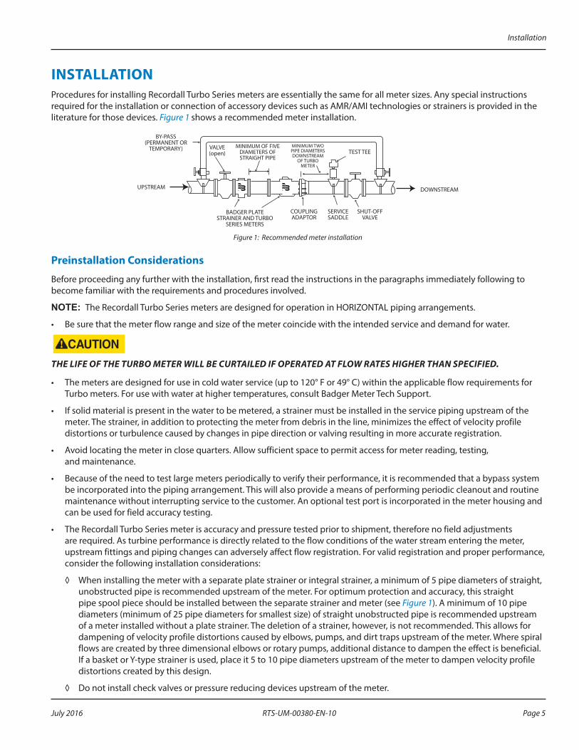
INSTALLATIONProcedures for installing Recordall Turbo Series meters are essentially the same for all meter sizes Any special instructions required for the installation or connection of accessory devices such as AMR/AMI technologies or strainers is provided in the literature for those devices Figure 1 shows a recommended meter installation
BADGER PLATESTRAINER AND TURBO
SERIES METERS
COUPLINGADAPTOR
SERVICESADDLE
SHUT-OFFVALVE
TEST TEEMINIMUM TWOPIPE DIAMETERSDOWNSTREAM
OF TURBOMETER
MINIMUM OF FIVEDIAMETERS OFSTRAIGHT PIPE
VALVE(open)
BY-PASS(PERMANENT OR
TEMPORARY)
UPSTREAM DOWNSTREAM
Figure 1: Recommended meter installation
Preinstallation Considerations
Before proceeding any further with the installation, first read the instructions in the paragraphs immediately following to become familiar with the requirements and procedures involved
NOTE:N The Recordall Turbo Series meters are designed for operation in HORIZONTAL piping arrangements
• Be sure that the meter flow range and size of the meter coincide with the intended service and demand for water
THE LIFE OF THE TURBO METER WILL BE CURTAILED IF OPERATED AT FLOW RATES HIGHER THAN SPECIFIED.
• The meters are designed for use in cold water service (up to 120° F or 49° C) within the applicable flow requirements for Turbo meters For use with water at higher temperatures, consult Badger Meter Tech Support
• If solid material is present in the water to be metered, a strainer must be installed in the service piping upstream of the meter The strainer, in addition to protecting the meter from debris in the line, minimizes the effect of velocity profile distortions or turbulence caused by changes in pipe direction or valving resulting in more accurate registration
• Avoid locating the meter in close quarters Allow sufficient space to permit access for meter reading, testing, and maintenance
• Because of the need to test large meters periodically to verify their performance, it is recommended that a bypass system be incorporated into the piping arrangement This will also provide a means of performing periodic cleanout and routine maintenance without interrupting service to the customer An optional test port is incorporated in the meter housing and can be used for field accuracy testing
• The Recordall Turbo Series meter is accuracy and pressure tested prior to shipment, therefore no field adjustments are required As turbine performance is directly related to the flow conditions of the water stream entering the meter, upstream fittings and piping changes can adversely affect flow registration For valid registration and proper performance, consider the following installation considerations:
◊ When installing the meter with a separate plate strainer or integral strainer, a minimum of 5 pipe diameters of straight, unobstructed pipe is recommended upstream of the meter For optimum protection and accuracy, this straight pipe spool piece should be installed between the separate strainer and meter (see Figure 1) A minimum of 10 pipe diameters (minimum of 25 pipe diameters for smallest size) of straight unobstructed pipe is recommended upstream of a meter installed without a plate strainer The deletion of a strainer, however, is not recommended This allows for dampening of velocity profile distortions caused by elbows, pumps, and dirt traps upstream of the meter Where spiral flows are created by three dimensional elbows or rotary pumps, additional distance to dampen the effect is beneficial If a basket or Y-type strainer is used, place it 5 to 10 pipe diameters upstream of the meter to dampen velocity profile distortions created by this design
◊ Do not install check valves or pressure reducing devices upstream of the meter
Installation
RTS-UM-00380-EN-10 Page 5 July 2016
◊ Valves immediately upstream of the meter should only be fully-open gate valves Butterfly valves are acceptable if they are 5 pipe diameters or more upstream from the meter Downstream, fully open gate or butterfly valves can be used
◊ The service saddle (or reducing tee), which is used for field accuracy testing, should be at least 2 pipe diameters downstream of the meter's outlet flange
◊ Unweighted check valves should not be located closer than 3 pipe diameters downstream of the meter
◊ Externally weighted check valves and pressure reducing devices should not be located closer than 5 pipe diameters of the meter
◊ When installing a Turbo meter and plate strainer of a size smaller than the pipe installation, to reduce the effect of jetting caused by the increase in flow velocity, a minimum of 5 pipe diameters of pipe equal in size to the meter, is required upstream of the meter Additional length is required if a sharp contraction or an eccentric reducer, rather than a concentric, tapered reducer is used
Installing the Meter Overall dimensions and laying lengths of each meter size are listed in the Recordall Turbo Series Meter Product Data Sheet Review the dimensional requirements, choose an installation point in the piping, and proceed as follows:
1 Measure precisely the overall length of the meter with gaskets attached to the inlet and outlet flange connections
2 Provide proper gap length in service piping
3 Install meter in the pipeline so that the flow arrow on the meter housing points in the same direction as water flow
4 With meter and gaskets in place, tighten flange connection bolts
5 To relieve possible strain on the piping, position a meter support under the meter housing where appropriate
TURBINE METERS MUST OPERATE IN A COMPLETELY FILLED LINE AT ALL TIMES. THE DOWNSTREAM PIPING MUST ALWAYS BE ARRANGED TO PROVIDE SUFFICIENT BACK PRESSURE TO MAINTAIN A FULL LINE AT THE METER. BY ELIMINATING AIR IN THE LINE, AS WELL AS SUDDEN FLOW SURGES, INACCURATE REGISTRATION AND DAMAGE TO THE TURBINE MECHANISM CAN BE AVOIDED.
Performance Checks
Any valves or devices controlling the flow of water through a Turbo meter must always be opened and closed SLOWLY to prevent shock loads that may damage the meter’s rotor assembly
Complete the following checks to ensure that a Turbo meter is properly installed and operational:
• Slowly open the upstream valve to apply water pressure to the meter and check for leaks Tighten the flange bolts as required
• Perform a functional test of the meter Slowly open valve on downstream side of the meter to evacuate any air that may have been trapped in the service line To effectively evacuate the air, run a minimum of 25% of the rated flow rate of the meter for at least 2 minutes When air has been eliminated, increase demand flow rate by further opening the downstream valve or valves Observe the register for correct direction of flow Continue to open the demand side valves to a fully open position The high flow pointer will now move in the proper direction Now open all applicable service valves
• Check the flow rate to verify that the flow does not exceed the maximum continuous duty specification The rate of flow can be quickly checked by timing the quantity registered through the meter in one minute
Installation
RTS-UM-00380-EN-10Page 6 July 2016
MAINTENANCEThis section is limited to information pertaining to the general maintenance of Badger Meter Recordall Turbo Series meters An exploded view of the meter, along with part numbers and descriptions, are provided in the Recordall Turbo Series Meters Parts List
Maintenance Equipment
The tools and equipment recommended for use in servicing and maintaining of Recordall Turbo Series meters consist of the usual complement of hand tools used by plumbers and mechanics
Preventive Maintenance
The purpose of preventive maintenance is to ensure efficient operation and long life of the meter by detecting and correcting any defect that might damage the meter or cause it to fail Preventive maintenance consists of periodic inspection, accuracy testing, and cleaning procedures
Periodic Inspection
• Visually inspect the meter for missing hardware, loose screws, broken or scratched register lenses or any other signs of wear or deterioration
• Verify that the meter is operating at the proper flow rate and pressure A loss in pressure, coupled with a decrease in flow rate, may indicate that the screen in the upstream pipeline—or the meter itself—is clogged with foreign material and needs cleaning
Cleaning
• Clean all dirt, grease, moisture or other foreign material from the exterior of the meter After cleaning, rinse thoroughly with water
• In the event that system pressure has been reduced and the upstream filter or meter is clogged, the foreign material must be flushed out To flush the screen, open the cleanout plug and purge the foreign material with fresh water from the service line If cleaning the screen does not restore system pressure, the Turbo meter also should be flushed by purging with fresh service water through the cleanout plugs located on the housing
• Integral Strainer Units: Before attempting service/maintenance of strainer section, system pressure must be removed After system pressure is removed, remove cover bolts and cover Clean out/flush strainer section of all loose particles/debris After cleaning is complete, reinstall screen and reassemble Return meter to normal service
Shutdown Instructions
If the turbo meter is to be shut down for an extended period of time or if it is being removed from service, Badger Meter recommends that the meter and measuring components be thoroughly flushed to prevent the settling out of undissolved solids or the accumulation of corrosive deposits If there is an upstream strainer in the line, it also should be flushed at this time
Maintenance
RTS-UM-00380-EN-10 Page 7 July 2016
Calibration Check and Adjustment
The accuracy of the Recordall Turbo Series meters is tested at the factory before shipment However, after a long period of service, it may be necessary to recalibrate a meter The meter can be tested for accuracy using appropriate connections with either a test tank of known volume or a test meter The meter can be tested in the setting by running output flow through the optional test port, if so equipped The Recordall Turbo Series integral calibration mechanism can be adjusted under line pressure, simplifying and reducing calibration time The following instructions are provided to assist in performing a calibration check and adjustment
Accuracy Test
IF THE OPTIONAL TEST PORT IS TO BE USED, UPSTREAM AND DOWNSTREAM VALVES MUST BE CLOSED PRIOR TO REMOVING PLUG AND INSTALLING APPROPRIATE CONNECTIONS. FAILURE TO DO SO CAN LEAD TO PLUG BEING EJECTED FROM HOUSING, CAUSING PERSONAL INJURY AND/OR PROPERTY DAMAGE. WHEREVER AN INSTALLATION IS EQUIPPED WITH A DRAIN VALVE FOR METER FLUSHING, OPEN THE DRAIN VALVE TO RELIEVE PRESSURE WITHIN THE METER. IF THE INSTALLATION DOES NOT HAVE A DRAIN VALVE, CAREFULLY LOOSEN TEST PLUG UNTIL IT BEGINS LEAKING. STOP AND WAIT FOR PRESSURE TO BLEED DOWN, THEN CONTINUE TO SLOWLY LOOSEN, MAKING CERTAIN THE PRESSURE IS COMPLETELY BLED OFF BEFORE REMOVING.
1 After installing the appropriate connections, test the meter by closing the downstream valve (if using integral test port) and slowly opening the upstream valve Slowly open the test circuit downstream valve to throttle flow for test purposes
2 Place a test tank of known volume at the output of the meter An alternative is to connect a calibrated test meter to the output Accuracy testing requires test volumes at least as large as the register test circle
3 As in testing the accuracy of any meter, the Recordall Turbo Series meter must first be purged of air by running water through the meter To effectively evacuate the air, run a minimum of 25% of the rated flow rate of the meter for at least 2 minutes
NOTE:N Good test practices, such as those outlined in the AWWA M6 manual, are required to perform reliable field accuracy tests Register "jump" can occur in some instances if valves are abruptly opened or closed While this jump is not accumulative (no affects in service billing), it can affect accuracy results (1% per division on a one test circle volumetric test)
4 Operate the meter until the test tank is filled to the calibrated level or the predetermined quantity has registered on the calibrated test meter Because accuracy may vary slightly with flow rate, it is recommended that the meter be tested at low, intermediate and high flows
5 Record the quantity registered on the meter during the test
6 Perform the following calculations to determine meter accuracy: (Quantity Registered on Meter)/(Test Tank or Test Meter Quantity) x 100=Meter Accuracy
Maintenance
RTS-UM-00380-EN-10Page 8 July 2016
Calibration
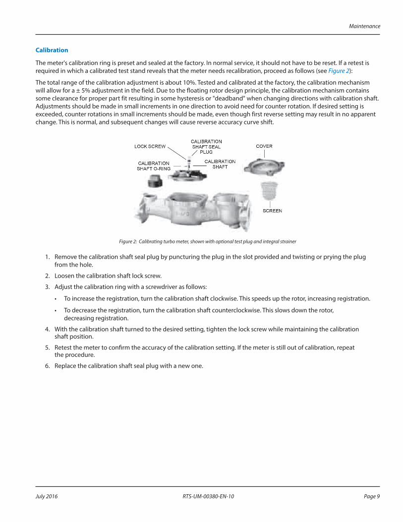
The meter's calibration ring is preset and sealed at the factory In normal service, it should not have to be reset If a retest is required in which a calibrated test stand reveals that the meter needs recalibration, proceed as follows (see Figure 2):
The total range of the calibration adjustment is about 10% Tested and calibrated at the factory, the calibration mechanism will allow for a ± 5% adjustment in the field Due to the floating rotor design principle, the calibration mechanism contains some clearance for proper part fit resulting in some hysteresis or "deadband" when changing directions with calibration shaft Adjustments should be made in small increments in one direction to avoid need for counter rotation If desired setting is exceeded, counter rotations in small increments should be made, even though first reverse setting may result in no apparent change This is normal, and subsequent changes will cause reverse accuracy curve shift
Figure 2: Calibrating turbo meter, shown with optional test plug and integral strainer
1 Remove the calibration shaft seal plug by puncturing the plug in the slot provided and twisting or prying the plug from the hole
2 Loosen the calibration shaft lock screw
3 Adjust the calibration ring with a screwdriver as follows:
• To increase the registration, turn the calibration shaft clockwise This speeds up the rotor, increasing registration
• To decrease the registration, turn the calibration shaft counterclockwise This slows down the rotor, decreasing registration
4 With the calibration shaft turned to the desired setting, tighten the lock screw while maintaining the calibration shaft position
5 Retest the meter to confirm the accuracy of the calibration setting If the meter is still out of calibration, repeat the procedure
6 Replace the calibration shaft seal plug with a new one
Maintenance
RTS-UM-00380-EN-10 Page 9 July 2016
SERVICING PARTS AND ASSEMBLIESWhen the performance of a Turbo meter indicates a need for servicing, refer to the following instructions pertaining to removal, inspection and installation of service parts and assemblies Also see the Recordall Turbo Series Meter Parts List for part numbers of replaceable components and correct ordering information If satisfactory repair cannot be made, contact Badger Meter
Removing the Meter HeadRecordall Turbo Series meters can be serviced without removing them from the line A typical installation would be equipped with drain and piping valves To inspect or replace components of the head assembly, close the upstream and downstream valves However, if the installation does not have a drain valve, proceed as follows to relieve pressure:
UPSTREAM AND DOWNSTREAM VALVES MUST BE CLOSED BEFORE ATTEMPTING TO REMOVE METER HEAD FROM HOUSING. FAILURE TO DO SO CAN LEAD TO THE HEAD BEING "EJECTED" FROM HOUSING, CAUSING PERSONAL INJURY AND/OR PROPERTY DAMAGE!
1 Loosen each of the head bolts about 2-3 turns Do not completely remove the bolts 2 If the O-ring between the meter head and the housing is secure and not leaking, pry the measuring element assembly
loose by inserting a screwdriver blade where the head and housing join together
BE SURE THAT ANY WATER COMING OUT OF THE METER HEAD DOES NOT SPRAY ONTO ELECTRICAL EQUIPMENT AND CREATE A SHOCK HAZARD.
3 Allow the meter to drain and relieve internal pressure 4 When pressure is relieved, remove the head bolts Lift the measuring element assembly from the housing
Removing the Local Register or EncoderThe Recordall Turbo Series meter registers and encoders are easily removable to facilitate in-line service
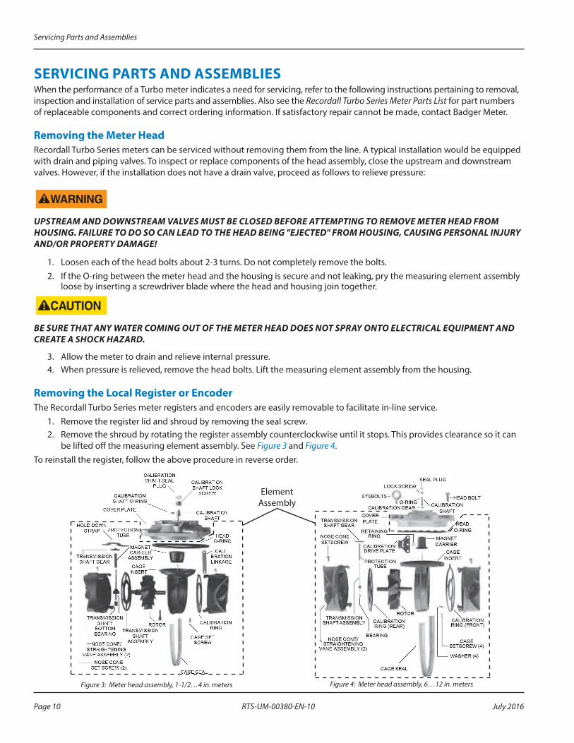
1 Remove the register lid and shroud by removing the seal screw 2 Remove the shroud by rotating the register assembly counterclockwise until it stops This provides clearance so it can
be lifted off the measuring element assembly See Figure 3 and Figure 4 To reinstall the register, follow the above procedure in reverse order
Figure 3: Meter head assembly, 1-1/2…4 in. meters Figure 4: Meter head assembly, 6…12 in. meters
Element Assembly
Servicing Parts and Assemblies
RTS-UM-00380-EN-10Page 10 July 2016
Removing the Measuring Element Assembly from the Cover Plate
NOTE:N A cage seal is installed in the 1-1/2…8 in Recordall Turbo Series so that the entire water volume flows through the measuring element
1 Remove the O-ring and cage seal
2 Check for damage and clean or replace prior to reassembly
3 To remove the measuring element from the cover, remove the calibration shaft seal plug and the lock screw (for 1-1/2…4 in sizes) See Figure 3
4 Place the cover register-side down on a table or flat surface
5 Lightly tap or press the calibration shaft from the wet side out of the bore in the cover (1-1/2…4 in only) Do not strike or bend the calibration linkage
NOTE:N If leakage was observed in the calibration shaft hole of the cover, replace the O-ring on the calibration shaft during re-install
6 The measuring element insert can be removed from the cover plate for service or replacement by removing the cage set screws (quantity of one for 1-1/2…4 in , quantity of 4 for the 6…12 in size) See Figure 3 and Figure 4
7 Holding the cover plate in one hand, rotate the thermoplastic element counter-clockwise until the bayonet-like tabs are aligned with open areas of the cover plate (1-1/2…4 in only)
8 Remove the element from the cover plate
Removing the Magnet Carrier
1 To remove the magnet carrier from the measuring element insert, lift it off the stainless steel pin See Figure 3 and Figure 4
2 Check the condition of the magnet and gear on the magnet carrier for damage or wear If significant wear or damage is present, replace the magnet carrier
3 Remove the hold-down strap (for the 1-1/2…4 in only) See Figure 3
4 Check the condition of the transmission shaft gear for damage or wear If significant wear or damage is present, replace the element assembly
Removing the Straightening Vanes/Nose Cone
The straightening vanes are an integral part of the upstream and downstream nose cone assemblies See Figure 3 and Figure 4
To gain access to them, remove the measuring element from the cover
Removing the upstream nose cone provides access to the rotor, calibration ring and the transmission assembly
Removing the upstream nose cone1 Remove the upstream nose cone setscrew For 1-1/2…4 in meters, slide the calibration linkage into the
cage insert stop
2 Take hold of the nose cone/straightening vanes and turn them clockwise, thereby disengaging the calibration linkage from the pin on the calibration ring and unlocking the bayonets of the nose cones from the cage (see Figure 5)
3 If the pin of the calibration ring has not disengaged the linkage, rotate the ring carefully by pushing the struts at the interior of the element (between the straightening vanes and the rotor) Pull the nose cone assembly out from the measuring element insert
4 For 6…12 in meters, remove the retaining ring that holds down the calibration drive plate, located under magnet carrier See Figure 4 and Figure 6 Remove drive plate Rotate calibration ring until pin clears slot of cage Take hold of the nose cone/straightening vanes and turn clockwise Pull the nose cone assembly out from the measuring element insert Remove rotor assembly
Servicing Parts and Assemblies
RTS-UM-00380-EN-10 Page 11 July 2016
Removing the Calibration Mechanism
To disassemble the calibration ring assembly (see Figure 3, Figure 4, "Removing the Meter Head" on page 10 and "Removing the Straightening Vanes/Nose Cone" on page 11):
1 For 1-1/2…4 in sizes only, remove the calibration shaft seal plug and unscrew the calibration shaft lock screw from the cover plate
2 Remove the calibration shaft thrust washer and calibration shaft Press the calibration shaft out of the cover plate from below
3 If a leak exists at the calibration shaft hole, remove the calibration shaft O-ring Before reinstalling the O-ring, apply a light coat of silicon grease to it
4 Clean all parts
To gain access to the calibration ring, remove the straightening vane/nose cone Follow the instructions in “Removing the Straightening Vanes/Nose Cone” on page 11
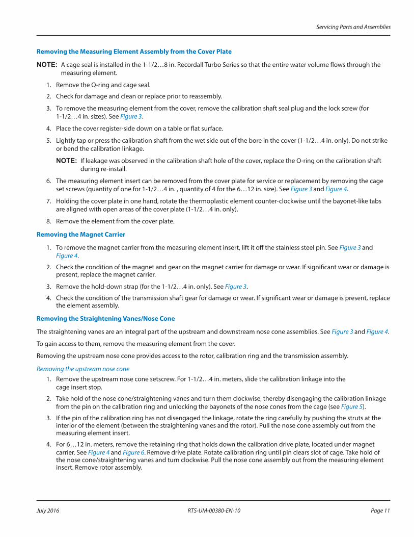
To remove the calibration ring from the nose cone assembly:
1 Align the ring slots with the bayonets of the nose cone assembly (located on inner ring of calibration ring)
2 Carefully lift the calibration ring from the nose cone assembly
3 Inspect the drive pin on the calibration ring If it is worn, replace the element assembly
CALIBRATION LINKAGE
ARROWTIP
CAGE INSERT
NOSE CONE
TOP SIDE
SMALL HOLE WITHCHAMFER UP
LARGE HOLE WITHCHAMFER DOWN
INTO CAGE THIS END
CALIBRATIONRING
PIN
NOSE CONESETSCREW
1-1/2…4 in. meters
RETAINING RINGTRANSMISSIONGEAR
CALIBRATIONDRIVE PLATE
CAGE INSERT(TOP VIEW)
PIN OFCALIBRATION
RING
NOSE CONESETSCREW
6…12 in. metersFigure 5: Calibration ring/linkage assemblies
Reassembling the Calibration Mechanism1 Align the pin on the perimeter of the calibration ring with the arrow tip on the nose cone assembly (see Figure 5)
2 For 1-1/2…4 in sizes, install the calibration linkage into the cage with the larger hole first to engage the calibration ring pin, with the side of chamfered edge of the hole towards the nose cone assembly (see Figure 5)
See “Reassembling the Rotor and Bearings” on page 13 before installing nose cones
3 For 1-1/2…4 in sizes, with the calibration linkage fully inserted to the cage stop, install the nose cone onto the cage and rotate it counter-clockwise to engage the pin of the ring to the calibration linkage Install the nose cone set screw
4 For 6…12 in sizes, reinstall the nose cone onto the cage, rotating it counterclockwise to engage the bayonet of the cone with the cage Install the set screw Reinstall the calibration drive plate onto the cage center pin boss, aligning the drive plate hole with the pin of the calibration ring The pin must be fully engaged with the hole of the drive plate for proper operation
5 To attach the element assembly to the cover, install the magnet carrier, then follow—in reverse order—the procedure for “Removing the Measuring Element Assembly from the Cover Plate” on page 11
After servicing or replacing the calibration mechanism, check the accuracy and calibration according to the instructions in "Calibration Check and Adjustment" on page 8
Servicing Parts and Assemblies
RTS-UM-00380-EN-10Page 12 July 2016
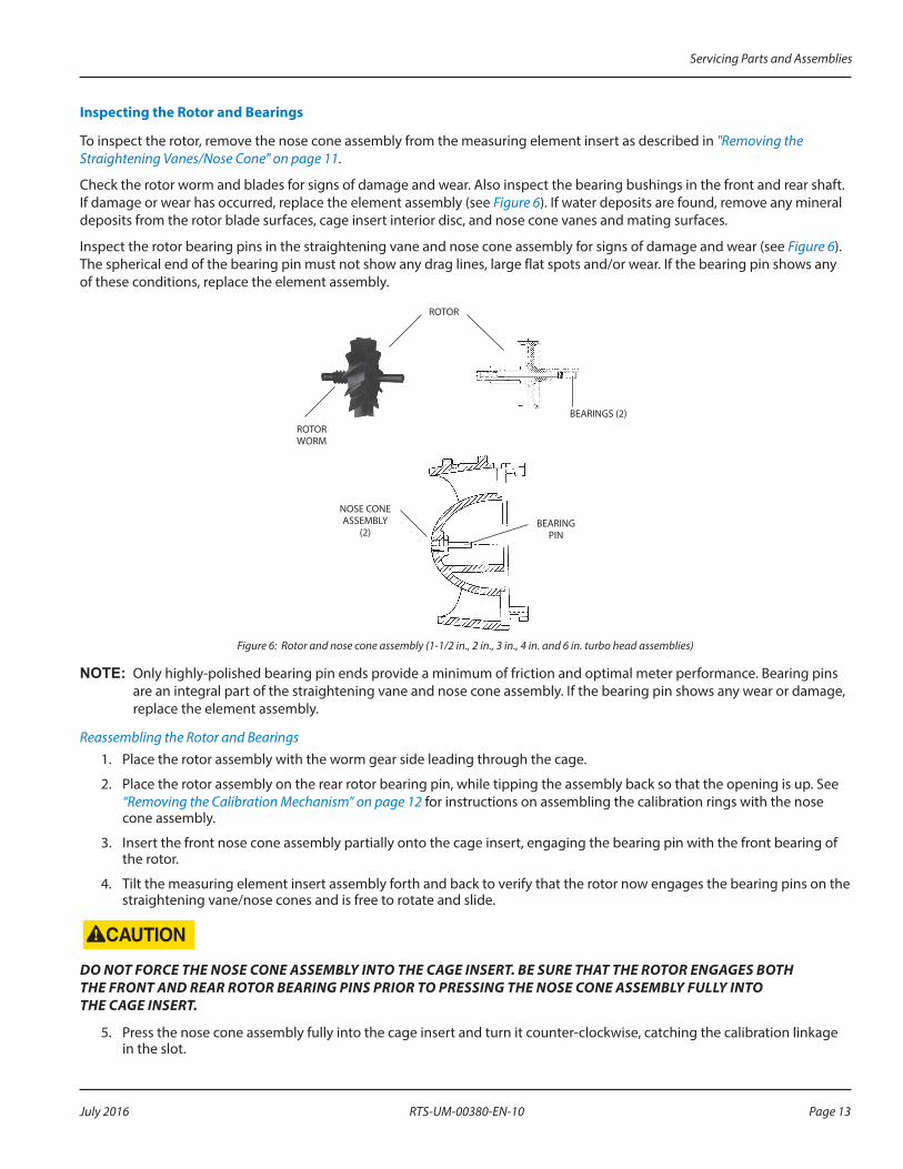
Inspecting the Rotor and Bearings
To inspect the rotor, remove the nose cone assembly from the measuring element insert as described in "Removing the Straightening Vanes/Nose Cone" on page 11
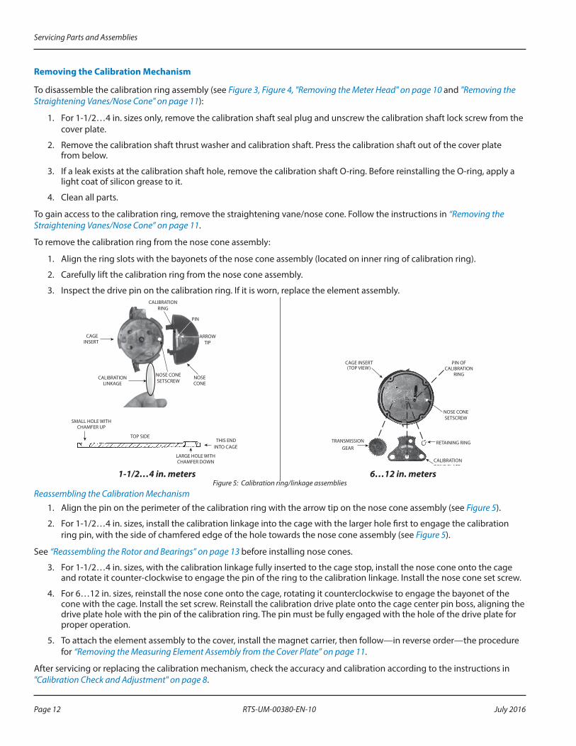
Check the rotor worm and blades for signs of damage and wear Also inspect the bearing bushings in the front and rear shaft If damage or wear has occurred, replace the element assembly (see Figure 6) If water deposits are found, remove any mineral deposits from the rotor blade surfaces, cage insert interior disc, and nose cone vanes and mating surfaces
Inspect the rotor bearing pins in the straightening vane and nose cone assembly for signs of damage and wear (see Figure 6) The spherical end of the bearing pin must not show any drag lines, large flat spots and/or wear If the bearing pin shows any of these conditions, replace the element assembly
ROTOR
ROTOR WORM
BEARINGS (2)
NOSE CONE ASSEMBLY
(2)BEARING
PIN
Figure 6: Rotor and nose cone assembly (1-1/2 in., 2 in., 3 in., 4 in. and 6 in. turbo head assemblies)
NOTE:N Only highly-polished bearing pin ends provide a minimum of friction and optimal meter performance Bearing pins are an integral part of the straightening vane and nose cone assembly If the bearing pin shows any wear or damage, replace the element assembly
Reassembling the Rotor and Bearings1 Place the rotor assembly with the worm gear side leading through the cage
2 Place the rotor assembly on the rear rotor bearing pin, while tipping the assembly back so that the opening is up See “Removing the Calibration Mechanism” on page 12 for instructions on assembling the calibration rings with the nose cone assembly
3 Insert the front nose cone assembly partially onto the cage insert, engaging the bearing pin with the front bearing of the rotor
4 Tilt the measuring element insert assembly forth and back to verify that the rotor now engages the bearing pins on the straightening vane/nose cones and is free to rotate and slide
DO NOT FORCE THE NOSE CONE ASSEMBLY INTO THE CAGE INSERT. BE SURE THAT THE ROTOR ENGAGES BOTH THE FRONT AND REAR ROTOR BEARING PINS PRIOR TO PRESSING THE NOSE CONE ASSEMBLY FULLY INTO THE CAGE INSERT.
5 Press the nose cone assembly fully into the cage insert and turn it counter-clockwise, catching the calibration linkage in the slot
Servicing Parts and Assemblies
RTS-UM-00380-EN-10 Page 13 July 2016
6 Verify that the rotor spins freely If it does not, remove the nose cone assembly and repeat the procedure
7 Install and tighten the nose cone assembly setscrew
8 Holding the cover plate in one hand, align the thermoplastic cage bayonet-like tabs with the slots in the cover plate (1-1/2…4 in only)
9 Rotate the element clockwise until the cage setscrew hole is aligned Install and tighten the cage setscrews (quantity of 1 for 1-1/2…4 in meters, a quantity 4 for the 6…12 in meter)
Reinstalling the Turbo Meter Head Assembly
• Use a new O-ring after each teardown and reassembly
• To provide a tight seal, make sure the surfaces of the housing and meter head are clean and free of any old O-ring material
• Be careful not to force the measuring element insert into the meter housing If you experience any binding, do not force the element into the housing Remove the element from the housing and properly reinsert the unit
NOTE:N Head bolts should be tightened similar to that on car tire First insert the bolts and snug-fit each Then, using a crisscross pattern, tighten the bolts down Following this pattern, the meter head will not turn and the rotor will remain perpendicular to the flow, eliminating any potential flow distortion Tighten the head bolts to: • 10…11 ft-lb for the 1-1/2 in and 2 in sizes • 35…40 ft-lb for the 3 in , 4 in and 6 in sizes • 65…76 ft-lb for the 8…12 in sizes
• Reinstall the local register or encoder to the meter
Placing the Meter Back in Service
1 Close the flushing system drain valve
2 Open the upstream valve partially, then open the downstream valve slightly to purge air from the service line
3 Open both valves completely
Servicing Parts and Assemblies
RTS-UM-00380-EN-10Page 14 July 2016
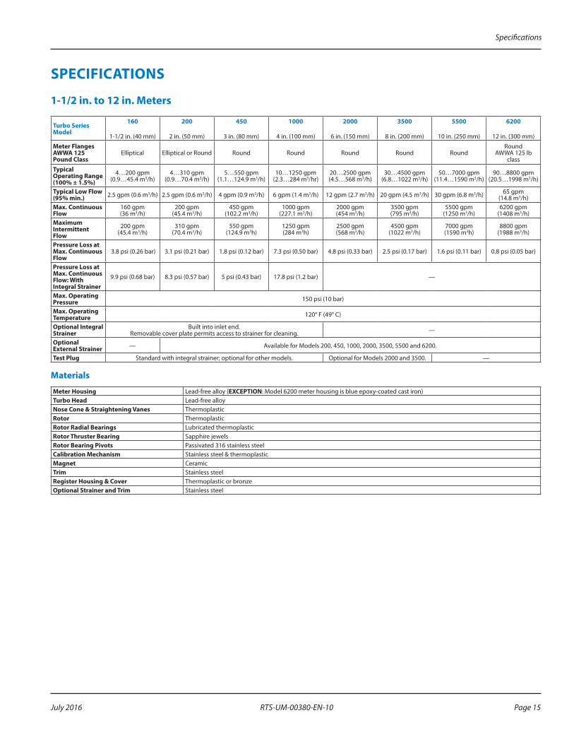
SPECIFICATIONS
1-1/2 in. to 12 in. Meters
Turbo Series Model
160
1-1/2 in (40 mm)
200
2 in (50 mm)
450
3 in (80 mm)
1000
4 in (100 mm)
2000
6 in (150 mm)
3500
8 in (200 mm)
5500
10 in (250 mm)
6200
12 in (300 mm)
Meter Flanges AWWA 125 Pound Class
Elliptical Elliptical or Round Round Round Round Round RoundRound