32
KRAMER ELECTRONICS LTD. USER MANUAL MODEL: VP-4x8 4x8 VGA/UXGA Matrix Switcher P/N: 2900-000372 Rev 3

KRAMER ELECTRONICS LTD.
USER MANUAL
MODEL:
VP-4x8 4x8 VGA/UXGA Matrix Switcher
P/N: 2900-000372 Rev 3

VP-4x8 – Contents i
Contents
1 Introduction 1 2 Getting Started 2 2.1 Achieving the Best Performance 2 2.2 Recycling Kramer Products 2 3 Overview 3 3.1 Defining the VP-4x8 4x8 VGA/UXGA Matrix Switcher 5 3.2 Using the IR Transmitter 7 4 Installing in a Rack 8 5 Connecting the VP-4x8 9 5.1 Connecting the VP-4x8 Rear Panel 9 5.2 Connecting the RS-232 Port to a PC or Controller 10 5.3 Connecting the RS-485 Port to a PC or Controller 11 5.4 Connecting the Ethernet Port 12 5.5 Setting the DIP-Switches 14 5.6 Cascading Machines 16 6 Operating the VP-4x8 18 6.1 Displaying Unit Characteristics 18 6.2 Confirming Settings 19 6.3 Storing/Recalling Input/Output Configurations 20 6.4 Locking the Front Panel 22 7 Technical Specifications 23 8 Serial Communication 24 8.1 Default Communication Parameters 24 8.2 Hex Code Table 24 9 Kramer Protocol 2000 25
Figures
Figure 1: UVP-4x8U 4x8 VGA/UXGA Matrix Switcher Front Panel 5 Figure 2: UVP-4x8U 4x8 VGA/UXGA Matrix Switcher Rear Panel 6 Figure 3: UVP-4x8U Underside View 7 Figure 4: Connecting the UVP-4x8U 4x8 VGA/UXGA Matrix Switcher 10 Figure 5: Crossed Cable RS-232 Connection 10 Figure 6: Straight Cable RS-232 Connection with a Null Modem Adapter 11 Figure 7: Local Area Connection Properties Window 13 Figure 8: Internet Protocol (TCP/IP) Properties Window 13 Figure 9: UVP-4x8U DIP-switches 14 Figure 10: Control Configuration via RS-232 and RS-485 17 Figure 11: Storing and Recalling using the Input/Output Buttons 20

VP-4x8 - Introduction 1
1 Introduction
Welcome to Kramer Electronics! Since 1981, Kramer Electronics has been
providing a world of unique, creative, and affordable solutions to the vast range of
problems that confront video, audio, presentation, and broadcasting professionals
on a daily basis. In recent years, we have redesigned and upgraded most of our
line, making the best even better!
Our 1,000-plus different models now appear in 11 groups that are clearly defined
by function: GROUP 1: Distribution Amplifiers; GROUP 2: Switchers and Routers;
GROUP 3: Control Systems; GROUP 4: Format/Standards Converters; GROUP 5:
Range Extenders and Repeaters; GROUP 6: Specialty AV Products; GROUP 7:
Scan Converters and Scalers; GROUP 8: Cables and Connectors; GROUP 9:
Room Connectivity; GROUP 10: Accessories and Rack Adapters and GROUP 11:
Sierra Products.
Congratulations on purchasing your Kramer VP-4x8 4x8 VGA/UXGA Matrix
Switcher, which is ideal for the following typical applications:
• Any professional display system requiring a true 4x8 computer graphics matrix operation
• Multimedia and presentation source, and acceptor selection

2 VP-4x8 - Getting Started
2 Getting Started
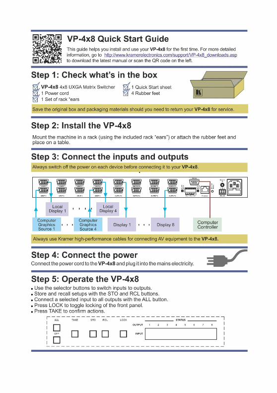
We recommend that you:
• Unpack the equipment carefully and save the original box and packaging materials for possible future shipment
• Review the contents of this user manual
• Use Kramer high-performance, high-resolution cables
• Use only the power cord that is supplied with this machine
Go to http://www.kramerelectronics.com to check for up-to-date user manuals, application programs, and to check if firmware upgrades are available (where appropriate).
2.1 Achieving the Best Performance
To achieve the best performance:
• Use only good quality connection cables to avoid interference, deterioration in signal quality due to poor matching, and elevated noise levels (often associated with low quality cables)
• Do not secure the cables in tight bundles or roll the slack into tight coils
• Avoid interference from neighboring electrical appliances that may adversely influence signal quality
• Position your Kramer VP-4x8 away from moisture, excessive sunlight and dust
2.2 Recycling Kramer Products
The Waste Electrical and Electronic Equipment (WEEE) Directive 2002/96/EC
aims to reduce the amount of WEEE sent for disposal to landfill or incineration by
requiring it to be collected and recycled. To comply with the WEEE Directive,
Kramer Electronics has made arrangements with the European Advanced
Recycling Network (EARN) and will cover any costs of treatment, recycling and
recovery of waste Kramer Electronics branded equipment on arrival at the EARN
facility. For details of Kramer’s recycling arrangements in your particular country
go to our recycling pages at http://www.kramerelectronics.com/support/recycling/.
i
VP-4x8 - Overview 3
3 Overview
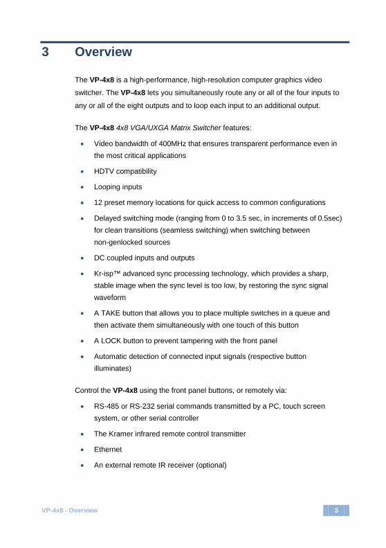
The VP-4x8 is a high-performance, high-resolution computer graphics video
switcher. The VP-4x8 lets you simultaneously route any or all of the four inputs to
any or all of the eight outputs and to loop each input to an additional output.
The VP-4x8 4x8 VGA/UXGA Matrix Switcher features:
• Video bandwidth of 400MHz that ensures transparent performance even in the most critical applications
• HDTV compatibility
• Looping inputs
• 12 preset memory locations for quick access to common configurations
• Delayed switching mode (ranging from 0 to 3.5 sec, in increments of 0.5sec) for clean transitions (seamless switching) when switching between non-genlocked sources
• DC coupled inputs and outputs
• Kr-isp™ advanced sync processing technology, which provides a sharp, stable image when the sync level is too low, by restoring the sync signal waveform
• A TAKE button that allows you to place multiple switches in a queue and then activate them simultaneously with one touch of this button
• A LOCK button to prevent tampering with the front panel
• Automatic detection of connected input signals (respective button illuminates)
Control the VP-4x8 using the front panel buttons, or remotely via:
• RS-485 or RS-232 serial commands transmitted by a PC, touch screen system, or other serial controller
• The Kramer infrared remote control transmitter
• Ethernet
• An external remote IR receiver (optional)

4 VP-4x8 - Overview
The VP-4x8 is a dependable and rugged unit that fits into one vertical space (1U)
of a standard 19-inch professional rack.
The RGBHV signals are connected on 15-pin HD pin connectors to reduce enclosure size.

VP-4x8 - Overview 5
VP-4x8 – Overview
5
3.1 Defining the VP-4x8 4x8 VGA/UXGA Matrix Switcher
This section defines the VP-4x8.
Figure 1: VP-4x8 4x8 VGA/UXGA Matrix Switcher Front Panel
# Feature Function
1 IR Receiver The red LED is illuminated when receiving signals from the infrared remote control transmitter 2 POWER Switch Illuminated switch for turning the unit ON or OFF 3 IN SELECTOR Buttons Select the input to switch to the output.
When a signal is detected, the input button illuminates in green 4 OUT SELECTOR Buttons Select the output to which the input is switched 5 ALL Button Pressing ALL followed by an INPUT button, connects that input to all outputs 6 OFF Button Press an OUT SELECTOR button and then an OFF button to disconnect that output from the inputs
Press the ALL button and then the OFF button to disconnect all the outputs 7 TAKE Button Pressing TAKE toggles the mode between the Confirm mode (in the Confirm mode, the TAKE button
illuminates) and the At Once mode (user confirmation per action is unnecessary) 8 STO (Store) Button Pressing STO followed by an input/output button stores the current setting 9 RCL (Recall) Button Pressing the RCL button and the corresponding IN/OUT button recalls a setup from the non-volatile
memory. The stored status flashes. Pressing a different IN/OUT button lets you view another setup. After making your choice, pressing the RCL button again implements the new status
10 LOCK Button Disengages the front panel switches 11 STATUS 7-segment Display Displays the selected input switched to the output (marked above each input)
Also displays the number of IN and OUT ports, the firmware version number, and the MACHINE #. See Section 6.1
6 VP-4x8 - Overview
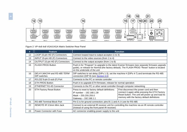
Figure 2: VP-4x8 4x8 VGA/UXGA Matrix Switcher Rear Panel
# Feature Function 12 LOOP 15-pin HD (F) Connectors Connect looped input to output acceptor (1 to 4) 13 INPUT 15-pin HD (F) Connectors Connect to the video sources (from 1 to 4) 14 OUTPUT 15-pin HD (F) Connectors Connect to the output acceptor (from 1 to 8) 15 FLASH PROG Button Push in for “Program” to upgrade to the latest Kramer firmware (see separate firmware upgrade
guide), or release for Normal (the factory default). The FLASH PROG “Reset” button is located on the underside of the unit
16 DELAY,MACH# and RS-485 TERM DIP-switches
DIP-switches to set delay (DIPs 1-3), set the machine # (DIPs 4-7) and terminate the RS-485 connection (DIP 8) (see Section 5.5)
17 RS-232 9-pin D-sub (F) Port Connects to the PC or remote controller 18 ETH PROG Button Push in to upgrade ETH firmware, release for normal operation 19 ETHERNET RJ-45 Connector Connects to the PC or other serial controller through computer networking 20 ETH Factory Reset Button Press to reset to factory default definitions:
IP number − 192.168.1.39 Mask – 255.255.255.0 Gateway – 192.168.1.1
First disconnect the power cord and then connect it again while pressing the ETH Factory Reset button. The unit will power up and load its memory with the factory default definitions
21 RS-485 Terminal Block Port Pin G is for ground connection; pins B (-) and A (+) are for RS-485 22 REMOTE IR 3.5mm Mini Jack Connect to an external IR receiver unit for controlling the machine via an IR remote controller
(instead of using the front panel IR receiver) 23 Power Connector with Fuse AC connector enabling power supply to the unit
6 VP-4x8 – O
verview
VP-4x8 - Overview 7
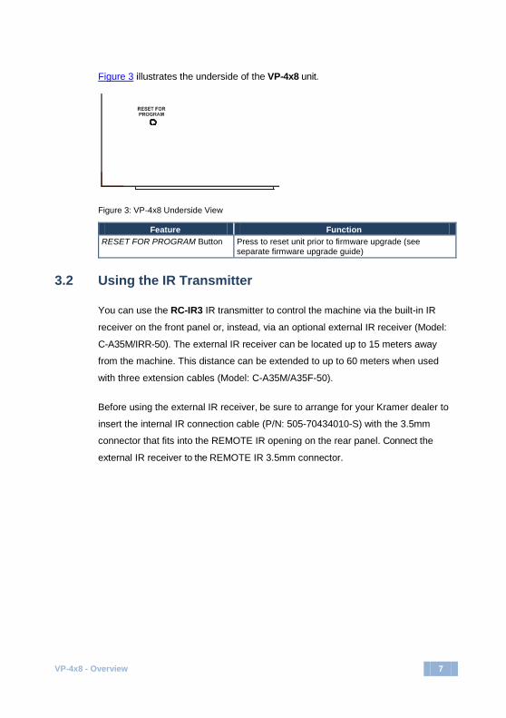
Figure 3 illustrates the underside of the VP-4x8 unit.
Figure 3: VP-4x8 Underside View
Feature Function RESET FOR PROGRAM Button Press to reset unit prior to firmware upgrade (see
separate firmware upgrade guide)
3.2 Using the IR Transmitter
You can use the RC-IR3 IR transmitter to control the machine via the built-in IR
receiver on the front panel or, instead, via an optional external IR receiver (Model:
C-A35M/IRR-50). The external IR receiver can be located up to 15 meters away
from the machine. This distance can be extended to up to 60 meters when used
with three extension cables (Model: C-A35M/A35F-50).
Before using the external IR receiver, be sure to arrange for your Kramer dealer to
insert the internal IR connection cable (P/N: 505-70434010-S) with the 3.5mm
connector that fits into the REMOTE IR opening on the rear panel. Connect the
external IR receiver to the REMOTE IR 3.5mm connector.
8 VP-4x8 - Installing in a Rack
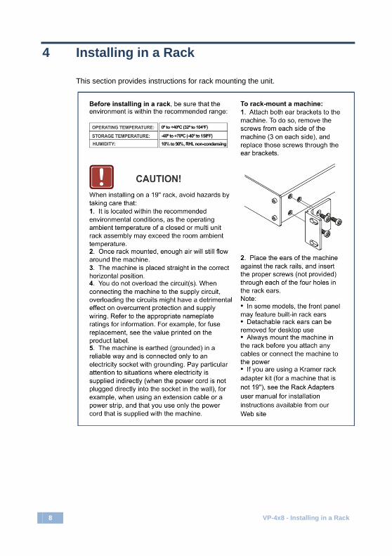
4 Installing in a Rack
This section provides instructions for rack mounting the unit.

VP-4x8 - Connecting the VP-4x8 9
5 Connecting the VP-4x8
This section describes how to:
• Connect the VP-4x8 rear panel (see Section 5.1)
• Connect the VP-4x8 to a controlling device via RS-232 (see Section 5.2), RS-485 (see Section 5.3) and/or the Ethernet (see Section 5.4)
• Set the DIP-switches (see Section 5.5)
• Connect several VP-4x8 machines (see Section 5.6)
Always switch off the power to each device before connecting it to your VP-4x8. After connecting your VP-4x8, connect its power and then switch on the power to each device.
5.1 Connecting the VP-4x8 Rear Panel
To connect the VP-4x8 as shown in Figure 4, do the following:
1. Connect up to 4 VGA/UXGA computer graphics sources to the INPUT
connectors. Not all inputs need to be connected.
2. Connect up to 4 VGA/UXGA output acceptors to the LOOP connectors (local
displays or inputs to another cascaded unit).
3. Connect up to 8 output connectors to the VGA/UXGA video acceptors
(displays or projectors). When less than eight outputs are required, connect only those outputs of the VP-4x8 that are required, and leave the other outputs unconnected.
4. Set the DIP-switches (see Section 5.5).
5. Connect a PC and/or controller (if required) to the RS-232 port (see Section
5.2) and/or RS-485 port (see Section 5.3).
6. Connect the power cord (not shown in Figure 4). We recommend that you use only the power cord that is supplied with this machine.
i

10 VP-4x8 - Connecting the VP-4x8
Figure 4: Connecting the VP-4x8 4x8 VGA/UXGA Matrix Switcher
5.2 Connecting the RS-232 Port to a PC or Controller
You can connect to the unit via a crossed RS-232 connection, using for example,
a PC. A crossed cable or null-modem is required as shown in method A and B
respectively. If a shielded cable is used, connect the shield to pin 5.
Method A (Figure 5)—Connect the RS-232 9-pin D-sub port on the unit via a
crossed cable (only pin 2 to pin 3, pin 3 to pin 2, and pin 5 to pin 5 need be
connected) to the RS-232 9-pin D-sub port on the PC.
Note: There is no need to connect any other pins.
Figure 5: Crossed Cable RS-232 Connection
12
6
37
48
59
12
6
37
48
59
PC
VP-4x8 - Connecting the VP-4x8 11
Hardware flow control is not required for this unit. In the rare case where a
controller requires hardware flow control, short pin 1 to 7 and 8, and pin 4 to 6 on
the controller side.
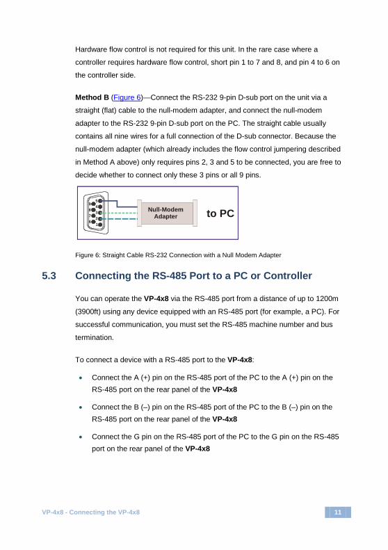
Method B (Figure 6)—Connect the RS-232 9-pin D-sub port on the unit via a
straight (flat) cable to the null-modem adapter, and connect the null-modem
adapter to the RS-232 9-pin D-sub port on the PC. The straight cable usually
contains all nine wires for a full connection of the D-sub connector. Because the
null-modem adapter (which already includes the flow control jumpering described
in Method A above) only requires pins 2, 3 and 5 to be connected, you are free to
decide whether to connect only these 3 pins or all 9 pins.
Figure 6: Straight Cable RS-232 Connection with a Null Modem Adapter
5.3 Connecting the RS-485 Port to a PC or Controller
You can operate the VP-4x8 via the RS-485 port from a distance of up to 1200m
(3900ft) using any device equipped with an RS-485 port (for example, a PC). For
successful communication, you must set the RS-485 machine number and bus
termination.
To connect a device with a RS-485 port to the VP-4x8:
• Connect the A (+) pin on the RS-485 port of the PC to the A (+) pin on the RS-485 port on the rear panel of the VP-4x8
• Connect the B (–) pin on the RS-485 port of the PC to the B (–) pin on the RS-485 port on the rear panel of the VP-4x8
• Connect the G pin on the RS-485 port of the PC to the G pin on the RS-485 port on the rear panel of the VP-4x8
12
6
37
48
59
to PCNull-ModemAdapter
12 VP-4x8 - Connecting the VP-4x8
5.4 Connecting the Ethernet Port
You can connect to the VP-4x8 to the Ethernet using either of the following
methods:
• Direct connection to the PC using a crossover cable (see Section 5.4.1)
• Connection via a network hub, switch, or router, using a straight-through cable (see Section 5.4.2)
5.4.1 Connecting the Ethernet Port Directly to a PC (Crossover Cable)
You can connect the Ethernet port of the VP-4x8 to the Ethernet port on your PC,
via a crossover cable with RJ-45 connectors.
This type of connection is recommended for identifying the VP-4x8 with the factory configured default IP address.
After connecting the Ethernet port, configure your PC as follows:
1. Right-click the My Network Places icon on your desktop.
2. Select Properties.
3. Right-click Local Area Connection Properties.
4. Select Properties.
The Local Area Connection Properties window appears.
5. Select the Internet Protocol (TCP/IP) and click the Properties Button (see
Figure 7).
i

VP-4x8 - Connecting the VP-4x8 13
Figure 7: Local Area Connection Properties Window
6. Select Use the following IP Address, and fill in the details as shown in
Figure 8. You can use any IP address in the range 192.168.1.1 to 192.168.1.255 (excluding 192.168.1.39) that is provided by your IT department.
7. Click OK.
Figure 8: Internet Protocol (TCP/IP) Properties Window

14 VP-4x8 - Connecting the VP-4x8
5.4.2 Connecting the Ethernet Port to a Network Hub (Straight-Through Cable)
You can connect the Ethernet port of the VP-4x8 to the Ethernet port on a network
hub or network router, via a straight-through cable with RJ-45 connectors.
5.4.3 Configuring Several Units via the Ethernet Port
To control several units via the Ethernet, connect the Master unit
(Machine # 1) via the Ethernet port to the LAN port of your PC. Use the PC to
initially configure the settings (see Section 5.4).
5.5 Setting the DIP-Switches
By default, all DIP-switches are set to OFF. Figure 9 illustrates the VP-4x8 DIP-switches:
Figure 9: VP-4x8 DIP-switches
DIPS Function Description 1, 2, 3 DELAY Determines switching delay time 4, 5, 6, 7 Machine # Determines the machine number (address) of
multiple units 8 RS-485 TERM ON for RS-485 line termination with 120Ω;
OFF for no RS-485 line termination
5.5.1 Setting the Delay
You can achieve clean transitions when switching between non-genlocked
sources by setting the delay time—ranging from 0 sec to 3.5 sec (In increments of
0.5 sec )—via the DELAY DIP-switches, as listed in the following table. The
VP-4x8 unit is shipped (its factory default state) with no delay, that is, the DELAY
DIP-switches are set up for a 0 sec delay.

VP-4x8 - Connecting the VP-4x8 15
Delay (sec) DIP 1 DIP 2 DIP 3 0 OFF OFF OFF 0.5 OFF OFF ON 1.0 OFF ON OFF 1.5 OFF ON ON 2.0 ON OFF OFF 2.5 ON OFF ON 3.0 ON ON OFF 3.5 ON ON ON
5.5.2 Setting the Machine Number
The Machine # determines the address of a VP-4x8 unit, specifying which VP-4x8
is being controlled when several units are connected to a PC or serial controller.
Set the Machine # on a VP-4x8 via MACH# DIPS 4, 5, 6 and 7, according to the
following table.
When connecting a single VP-4x8, set the Machine # to 1. When connecting more
than one VP-4x8, set the first machine connected to the PC (Master) as Machine #
1 (set DIPs 4 to 7 OFF).
Mach. # DIP 4 DIP 5 DIP 6 DIP 7 1 OFF OFF OFF OFF 2 OFF OFF OFF ON 3 OFF OFF ON OFF 4 OFF OFF ON ON 5 OFF ON OFF OFF 6 OFF ON OFF ON 7 OFF ON ON OFF 8 OFF ON ON ON 9 ON OFF OFF OFF
10 ON OFF OFF ON 11 ON OFF ON OFF 12 ON OFF ON ON 13 ON ON OFF OFF 14 ON ON OFF ON 15 ON ON ON OFF 16 ON ON ON ON
16 VP-4x8 - Connecting the VP-4x8
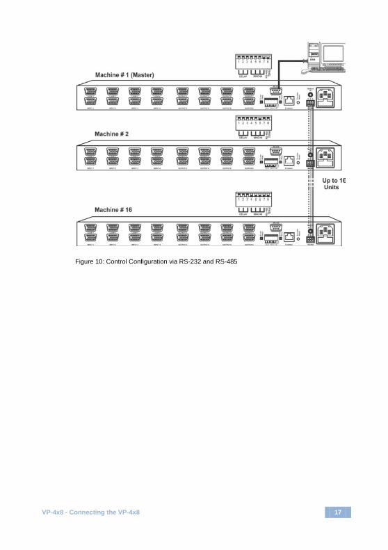
5.6 Cascading Machines
You can cascade up to 16 VP-4x8 units with control from a PC or serial controller
(see Figure 10).
To cascade up to 16 individual VP-4x8 units via RS-485, do the following:
1. Connect the VGA/UXGA sources and acceptors, as Section 5.1 describes.
2. Connect the RS-232 (or RS-485) port on the first VP-4x8 unit to the PC
using the null-modem adapter provided with the machine (recommended),
as Section 5.2 describes.
3. Connect the RS-485 terminal block port on the first unit to the RS-485 port
on the second VP-4x8 unit and so on, connecting all the RS-485 ports.
4. Set the DIP-switches, as shown in Section 5.5:
Set the first VP-4x8 unit as Machine # 1 and the following 15 VP-4x8 units as Machine # 2 to Machine # 16, according to Section 5.5.2
Set DIP 8 ON on the first and last VP-4x8 units (terminating the RS-485 line at 120Ω). Set DIP 8 OFF on the other VP-4x8 units
Set DIP 5, DIP 6 and DIP 7 OFF on all VP-4x8 units
VP-4x8 - Connecting the VP-4x8 17
Figure 10: Control Configuration via RS-232 and RS-485

18 VP-4x8 - Operating the VP-4x8
6 Operating the VP-4x8
You can operate your VP-4x8 via:
• The front panel buttons
• RS-232/RS-485 serial commands transmitted by a touch screen system, PC, or other serial controller
• The Kramer RC-IR2 Infrared Remote Control Transmitter
• The Ethernet
6.1 19BDisplaying Unit Characteristics
The STATUS 7-segment display shows three sets of information, as shown in the
following table:
The STATUS Display Shows: When:
Device type: VP-4x8
Immediately (and automatically) after switching on the power
Unit characteristics: Firmware version, Machine number
Immediately (and automatically) after switching on the power
Normal display: Inputs switched to the outputs
During normal operation, appears a few seconds after the first display
VP-4x8 - Operating the VP-4x8 19
6.2 Confirming Settings
You can choose to work in the At Once or the Confirm mode.
In the At Once mode (the TAKE button is not illuminated):
• Pressing an OUT-IN combination implements the switch immediately
• You save time as execution is immediate and actions require no user confirmation
• No protection is offered against changing an action in error
In the Confirm mode (TAKE button is illuminated):
• You can key-in several actions and then confirm them by pressing the TAKE button, to simultaneously activate the multiple switches
• Every action requires user confirmation, protecting against erroneous switching
• Execution is delayed until the user confirms the action Not pressing the TAKE button within one minute aborts the action.
6.2.1 Toggling between the At Once and Confirm Modes
To toggle between the At Once and Confirm modes, do the following:
1. Press the dim TAKE button to toggle from the At Once mode (in which the
TAKE button is dim) to the Confirm mode (in which the TAKE button
illuminates).
Actions now require user confirmation and the TAKE button illuminates.
2. Press the illuminated TAKE button to toggle from the Confirm mode back to
the At Once mode.
Actions no longer require user confirmation and the TAKE button no longer
illuminates.
20 VP-4x8 - Operating the VP-4x8
6.2.2 Confirming a Switching Action
To confirm a switching action (in the Confirm mode), do the following:
1. Press an OUT-IN combination.
The corresponding 7-segment Display flashes. The TAKE button also
flashes.
2. Press the flashing TAKE button to confirm the action.
The corresponding 7-segment Display no longer flashes. The TAKE button
illuminates.
To confirm several actions (in the Confirm mode), do the following:
1. Press each OUT-IN combination in sequence.
The corresponding 7-segment display flashes. The TAKE button also
flashes.
2. Press the flashing TAKE button to confirm all the actions.
The corresponding 7-segment display no longer flashes. The TAKE button
illuminates.
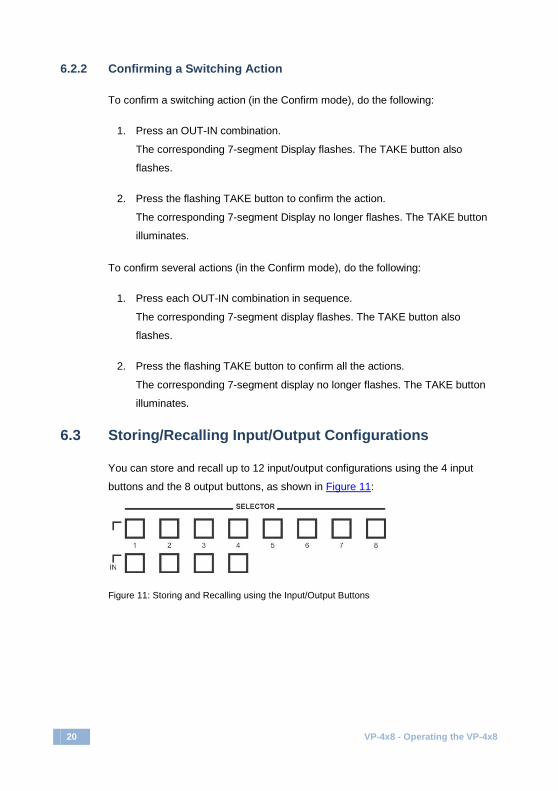
6.3 Storing/Recalling Input/Output Configurations
You can store and recall up to 12 input/output configurations using the 4 input
buttons and the 8 output buttons, as shown in Figure 11:
Figure 11: Storing and Recalling using the Input/Output Buttons

VP-4x8 - Operating the VP-4x8 21
6.3.1 Storing an Input/Output Configuration
To store the current status in memory, do the following:
1. Press the STO button.
The STO button flashes.
2. Press one of the 12 INPUT/OUTPUT buttons (the setup # of the current
status). If in the Confirm mode, press the flashing TAKE button to confirm
the action.
The memory stores the data at that reference.
6.3.2 Recalling an Input/Output Configuration
To recall an input/output configuration, do the following:
1. Press the RCL button.
The RCL button flashes.
2. Press the appropriate INPUT/OUTPUT button (the button # corresponding to
the setup #). If in the Confirm mode, that setup configuration flashes in the
7-segment display, together with the RCL button and the TAKE button, and
is only implemented after pressing the TAKE button.
The memory recalls the stored data from that reference.
Tip: If you cannot remember which input/output configuration is the one that you want, set to the Confirm mode and manually scan all the input/output configurations until you locate it.
6.3.3 Deleting an Input/Output Configuration
To delete an input/output configuration, do the following:
1. Press the STO and RCL buttons simultaneously.
Both the STO and RCL buttons flash.
2. Press the appropriate INPUT/OUTPUT button.
This erases that specific input/output configuration from the memory, leaving
it empty and available. Storing a new configuration over a previous configuration (without deleting it first) replaces the previous configuration
i
22 VP-4x8 - Operating the VP-4x8
6.4 Locking the Front Panel
To prevent changing the settings accidentally or tampering with the unit via the
front panel buttons, lock your VP-4x8. Unlocking releases the protection
mechanism.
Locking the front panel does not stop operation over RS-232, RS-485 or the Ethernet.
To lock the VP-4x8:
• Press the LOCK button for more than two seconds, until the LOCK button lights The front panel is locked. Pressing a button has no effect other than causing the LOCK button to flash
To unlock the VP-4x8:
• Press the lit LOCK button for more than two seconds, until the LOCK button no longer lights The front panel unlocks

VP-4x8 - Technical Specifications 23
7 Technical Specifications
INPUTS: 4 computer graphics video on 15-pin HD connectors (VGA through UXGA)
OUTPUTS: 8 computer graphics video on 15-pin HD connectors (VGA through UXGA)
MAX. OUTPUT LEVEL: 1.5Vpp BANDWIDTH (-3dB): 400MHz DIFF. GAIN: 0.04% DIFF. PHASE: 0.04Deg K-FACTOR: <0.05% S/N RATIO: 75dB CROSSTALK (all hostile): –53dB CONTROLS: 22 front panel buttons, RS-232, RS-485, Ethernet COUPLING: DC POWER SOURCE: 100–240V AC, 50/60Hz, 23VA OPERATING TEMPERATURE: 0° to +40°C (32° to 104°F) STORAGE TEMPERATURE: -40° to +70°C (-40° to 158°F) HUMIDITY: 10% to 90%, RHL non-condensing DIMENSIONS 19" x 7" x 1U W, D, H, rack mountable WEIGHT: 2.7kg (6lbs) approx ACCESSORIES: Power cord, null-modem adapter, Windows®-based
Kramer control software, infrared remote control transmitter
OPTIONS: External remote IR receiver cable Specifications are subject to change without notice at http://www.kramerelectronics.com
24 VP-4x8 - Serial Communication
8 Serial Communication
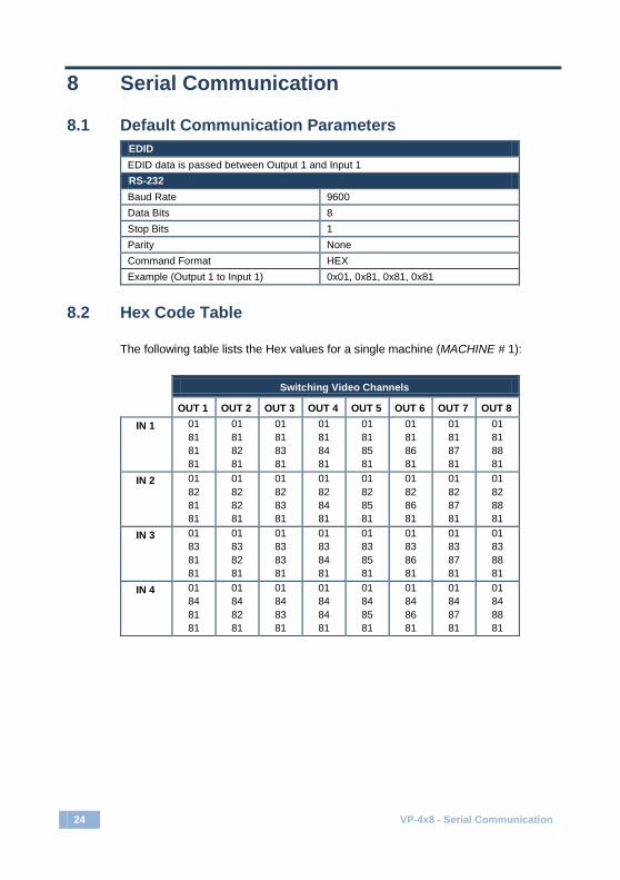
8.1 Default Communication Parameters EDID EDID data is passed between Output 1 and Input 1 RS-232 Baud Rate 9600 Data Bits 8 Stop Bits 1 Parity None Command Format HEX Example (Output 1 to Input 1) 0x01, 0x81, 0x81, 0x81
8.2 Hex Code Table
The following table lists the Hex values for a single machine (MACHINE # 1):
Switching Video Channels
OUT 1 OUT 2 OUT 3 OUT 4 OUT 5 OUT 6 OUT 7 OUT 8 IN 1 01
81 81 81
01 81 82 81
01 81 83 81
01 81 84 81
01 81 85 81
01 81 86 81
01 81 87 81
01 81 88 81
IN 2 01 82 81 81
01 82 82 81
01 82 83 81
01 82 84 81
01 82 85 81
01 82 86 81
01 82 87 81
01 82 88 81
IN 3 01 83 81 81
01 83 82 81
01 83 83 81
01 83 84 81
01 83 85 81
01 83 86 81
01 83 87 81
01 83 88 81
IN 4 01 84 81 81
01 84 82 81
01 84 83 81
01 84 84 81
01 84 85 81
01 84 86 81
01 84 87 81
01 84 88 81

VP-4x8 - Kramer Protocol 2000 25
9 Kramer Protocol 2000
This RS-232/RS-485 communication protocol uses four bytes of information as
defined below.
For RS-232, a null-modem connection between the machine and controller is
used. The default data rate is 9600 baud, with no parity, 8 data bits and 1 stop bit.
MSB LSB 1st Byte DESTINATION INSTRUCTION 0 D N5 N4 N3 N2 N1 N0 7 6 5 4 3 2 1 0 2nd Byte INPUT 1 I6 I5 I4 I3 I2 I1 I0 7 6 5 4 3 2 1 0 3rd Byte OUTPUT 1 O6 O5 O4 O3 O2 O1 O0 7 6 5 4 3 2 1 0 4th Byte MACHINE NUMBER 1 OVR X M4 M3 M2 M1 M0 7 6 5 4 3 2 1 0
1st Byte: Bit 7 – Defined as 0
D – DESTINATION 0 – Sends information to the switchers (from the PC) 1 – Sends information to the PC (from the switcher)
N5…N0 – INSTRUCTION The 6-bit INSTRUCTION defines the function performed by the switcher(s). If a function is performed using the machine’s keyboard, these bits are set with the INSTRUCTION NO. performed. The instruction codes are defined according to the table below (INSTRUCTION NO. is the value set in N5…N0). 2nd Byte: Bit 7 – Defined as 1 I6…I0 – INPUT When switching (i.e. instruction codes 1 and 2), the 7-bit INPUT is set as the input number to be switched. If switching is done using the machine’s front panel, these bits are set with the INPUT NUMBER switched. For other operations, these bits are defined according to the table. 3rd Byte: Bit 7 – Defined as 1 O6…O0 – OUTPUT When switching (i.e. instruction codes 1 and 2), the 7-bit OUTPUT is set as the output number to be switched. If switching is done using the machine’s front panel, these bits are set with the OUTPUT NUMBER switched. For other operations, these bits are defined according to the table. 4th Byte: Bit 7 – Defined as 1 Bit 5 – Don’t care OVR – Machine number override M4…M0 – MACHINE NUMBER This byte is used to address machines in a system by their machine numbers. When several machines are controlled from a single serial port, they are usually configured together and each machine has an individual machine number. If the OVR bit is set, then all machine numbers accept (implement) the command and the addressed machine replies. When a single machine is controlled over the serial port, always set M4…M0 to 1, and make sure that the machine itself is configured as MACHINE NUMBER = 1. All the values in the table are decimal, unless otherwise stated.

26 VP-4x8 - Kramer Protocol 2000
Instruction Codes for Protocol 2000 Instruction Definition for Specific Instruction Notes
# Description Input Output 0 RESET VIDEO 0 0 1 1 SWITCH VIDEO Set equal to video input that is
switched (0 = disconnect)
Set equal to video output that is switched (0 = to all the outputs)
2, 15
3 STORE VIDEO STATUS Set as SETUP # To store To delete
2, 3, 15
4 RECALL VIDEO STATUS
Set as SETUP # 0 2, 3, 15
5 REQUEST STATUS OF A VIDEO OUTPUT
Set as SETUP # Equal to output number whose status is required
4, 3
15 REQUEST WHETHER SETUP IS DEFINED / VALID INPUT IS DETECTED
SETUP # or Input # or Output #
0 – For checking if setup is defined 1 – For checking if input is valid 2 – For checking if output is valid 3 – For checking if EDID output is valid
8
16 ERROR / BUSY For invalid / valid input (i.e. OUTPUT byte = 4 or OUTPUT byte = 5), this byte is set as the input #; For invalid / valid output (i.e. OUTPUT byte=7 or OUTPUT byte=8), this byte is set as the output#
0 – Error 1 – Invalid instruction 2 – Out of range 3 – Machine busy 4 – Invalid input 5 – Valid input 6 – RX buffer overflow 7 – Invalid output 8 – Valid output 9 – Valid EDID
9, 25
30 LOCK FRONT PANEL 0 – Unlock panel 1 – Lock panel
0 2
31 REQUEST WHETHER PANEL IS LOCKED
0 0 16
57 SET AUTO-SAVE I3 – No save I4 – Auto save
0 12, 2
61 IDENTIFY MACHINE 1 – Video machine name 2 – Audio machine name 3 – Video software version 4 – Audio software version 5 – RS-422 controller name 6 – RS-422 controller version 7 – Remote control name 8 – Remote software version 9 – Protocol 2000 revision 10 – Control data machine name 11 – Control data software version
For names: 0 – Request first 4 digits 1 – Request first suffix 2 – Request second suffix 3 – Request third suffix 10 – Request first prefix 11 – Request second prefix 12 – Request third prefix For versions: 0 – main board or the number of external board
13
62 DEFINE MACHINE 1 – Number of inputs 2 – Number of outputs 3 – Number of setups
1 – For video 2 – For audio 3 – For SDI 4 – For remote panel 5 – For RS-422 controller 6 – For control data
14
NOTES on the above table: NOTE 1 – When the master switcher is reset, (e.g. when it is turned on), the reset code is sent to the PC. If this code is sent to a switcher, it resets according to the present power-down settings.

VP-4x8 - Kramer Protocol 2000 27
NOTE 2 – These are bi-directional definitions. If the switcher receives the code, it performs the instruction. If the instruction is performed (due to a keystroke operation on the front panel), then these codes are sent. For example, if the PC sends HEX code: 01 85 88 83 then the switcher (machine 3) switches input 5 to output 8. If the user switches input 1 to output 7 using the front panel buttons, the switcher sends HEX code: 41 81 87 83 to the PC. When the PC sends one of the commands in this group to the switcher, if the instruction is valid, the switcher replies by sending the same four bytes to the PC that it received (except for the first byte, where the DESTINATION bit is set high). NOTE 3 – SETUP # 0 is the present setting. SETUP # 1 and higher are the settings saved in the switcher's memory, (i.e. those used for Store and Recall). NOTE 4 – The reply to a REQUEST instruction is as follows: the same instruction and INPUT codes that were sent are returned, and the OUTPUT is assigned the value of the requested parameter. The replies to instructions 10 and 11 are according to the definitions in instructions 7 and 8 respectively. For example, if the present status of machine number 5 is breakaway setting, then the reply to HEX code: 0B 80 80 85 is HEX code: 4B 80 81 85. NOTE 8 – The reply is as in NOTE 4 above, except that the OUTPUT is assigned with the value 0 if the setup is not defined / no valid input is detected; or 1 if it is defined / valid input is detected. NOTE 9 - An error code is returned to the PC if an invalid instruction code was sent to the switcher, or if a parameter associated with the instruction is out of range (e.g. trying to save to a setup greater than the highest one, or trying to switch an input or output greater than the highest one defined). This code is also returned to the PC if an RS-232 instruction is sent while the machine is being programmed from the front panel. Reception of this code by the switcher is not valid. NOTE 12 – Under normal conditions, the machine's present status is saved each time a change is made. The "power-down" save (auto-save) may be disabled using this code. Note that whenever the machine is turned on, the auto-save function is set. NOTE 13 – This is a request to identify the switcher/s in the system. If the OUTPUT is set as 0, and the INPUT is set as 1, 2, 5 or 7, the machine sends its name. The reply is the decimal value of the INPUT and OUTPUT. For example, for a 2216, the reply to the request to send the audio machine name is HEX code: 7D 96 90 81 (i.e. 128dec+ 22dec for 2nd byte, and 128dec+ 16dec for 3rd byte). If the request for identification is sent with the INPUT set as 3 or 4, the appropriate machine sends its software version number. Again, the reply would be the decimal value of the INPUT and OUTPUT - the INPUT representing the number in front of the decimal point, and the OUTPUT representing the number after it. For example, for version 3.5, the reply to the request to send the version number would be HEX code: 7D 83 85 81 (i.e. 128dec+ 3dec for 2nd byte, 128dec+ 5dec for 3rd byte). If the OUTPUT is set as 1, then the ASCII coding of the lettering following the machine’s name is sent. For example, for the VS-7588YC, the reply to the request to send the first suffix would be HEX code: 7D D9 C3 81 (i.e. 128dec+ ASCII for “Y”; 128dec+ ASCII for “C”). NOTE 15 – When the OVR bit (4th byte) is set, then the video commands have universal meaning. For example, instruction 1 (SWITCH VIDEO) causes all units (including audio, data, etc.) to switch. Similarly, if a machine is in FOLLOW mode, it performs any video instruction. NOTE 16 – The reply to the REQUEST WHETHER PANEL IS LOCKED is the same as in NOTE 4 above, except that OUTPUT is assigned with the value 0 if the panel is unlocked, or 1 if it is locked.
28 VP-4x8 - Kramer Protocol 2000

For the latest information on our products and a list of Kramer distributors, visit our Web site where updates to this user manual may be found.
We welcome your questions, comments, and feedback. Web site: www.kramerelectronics.com E-mail: [email protected]
P/N: 2900-000372 Rev: 3
! SAFETY WARNINGDisconnect the unit from the powersupply before opening and servicing


