237
User Manual LON M-Series User Manual LON M- Series Version 1.11 Moers, 22/01/2013 Version 1.11.122 Page 1 of 237 22/01/2013

User Manual LON M-Series
User Manual LON M-Series
Version 1.11
Moers, 22/01/2013
Version 1.11.122 Page 1 of 237 22/01/2013

User Manual LON M-Series
Content
1. Introduction.....................................................................................................4
1.1. Explanations of pictograms used.......................................................................41.2. Use of the manual....................................................................................................5
2. Product description.......................................................................................6
2.1. Safety information...................................................................................................62.2. Order information....................................................................................................72.3. sistema MC.................................................................................................................92.4. lumina BE8...............................................................................................................132.5. lumina SA4...............................................................................................................162.6. lumina SA8..............................................................................................................202.7. lumina ST4...............................................................................................................242.8. lumina DAL4/8/16 .................................................................................................282.9. ombra BA2................................................................................................................332.10. ombra BA2-3E..........................................................................................................372.11. ombra BA4................................................................................................................412.12. ombra BA4-DC........................................................................................................452.13. ombra BA4/BA8/16-SMI......................................................................................492.14. clima AA4-10V .......................................................................................................582.15. clima AA8-10V ........................................................................................................612.16. clima AA4.................................................................................................................642.17. clima AA8.................................................................................................................662.18. clima LA2-3..............................................................................................................682.19. clima AA8-MP..........................................................................................................72
3. Applications..................................................................................................76
3.1. Application data.....................................................................................................763.2. Hardware support..................................................................................................763.3. Automation functions...........................................................................................77
4. Setting-up and configuring a device......................................................79
4.1. Setting up the device............................................................................................794.2. Configuring the device.........................................................................................794.3. Module Configuration .........................................................................................844.4. Object configuration...........................................................................................1444.5. Configuration of groups.....................................................................................2034.6. Management..........................................................................................................210
Version 1.11.122 Page 2 of 237 22/01/2013

User Manual LON M-Series
5. Appendix......................................................................................................214
5.1. Support....................................................................................................................2145.2. Warranty and liability........................................................................................2145.3. spega e.control plug-ins....................................................................................2145.4. Device templates - Interfaces..........................................................................2205.5. Glossary..................................................................................................................237
Version 1.11.122 Page 3 of 237 22/01/2013

User Manual LON M-Series
1. IntroductionThank you for choosing a spega product. This product has been designed and optimised for use in building automation. To learn what the device can do and how to operate it, we recommend that you read this handbook carefully. It tells you all you need to know about how the device works, how to assemble it and how to set its parameters.
Please keep this manual in a place that is accessible to all users!
1.1. Explanations of pictograms usedThis guide uses pictograms as warning symbols, to make it easy to handle the equipment safely and get it working fully.
VOLTAGE: indicates immediate danger of a harmful electric shock if disregarded. This could result in severe or fatal injuries (to persons).
WARNING: indicates other immediate dangers if disregarded. This could result in severe or fatal injuries (to persons).
CAUTION: indicates a source of danger which could lead to property or environmental damage if disregarded.
INFORMATION: indicates recommendations for use which must always be followed to guarantee smooth operation. Failure to observe these, however, will not result in damage to the equipment.
Version 1.11.122 Page 4 of 237 22/01/2013

User Manual LON M-Series
1.2. Use of the manualThis manual is intended for all groups of persons involved in the planning, installation, commissioning and maintenance of the system. A overview of which chapter is relevant for which group of persons is shown below.
Intro
duct
ion
Pro
duct
des
crip
tion
App
licat
ions
Setti
ng-u
p an
d co
nfig
urin
g a
devi
ce
Gen
eral
han
dlin
g of
the
plug
-ins
Dev
ice
tem
plat
es -
inte
rface
s
Owners Planners Electrical specialists Systems integrators
Version 1.11.122 Page 5 of 237 22/01/2013

User Manual LON M-Series
2. Product descriptionThe LON M-series modular system comprises a sistema MC LON universal controller and one or more modular actuators which can be used together in almost any configuration. The controller is the intelligent interface between the LON network and the modular actuators.
Device plug-ins and plug-ins for the function objects are provided for the detailed configuration of the modular system.
2.1. Safety informationPlease note the following safety information:
The device function is determined by the application program. Only programs which have been by released by spega for the device may be loaded.
The system installer must ensure that the application program and the related parametrization conform to the wiring and intended application of the device.
The relevant standards, directives, requirements and regulations of the respective country must be observed when installing electrical equipment.
Version 1.11.122 Page 6 of 237 22/01/2013
Figure 1: M-series actuators with max. 24 channels which can be freely combined

User Manual LON M-Series
2.2. Order informationOrder # Product Description
121 000 C sistema MC LON Universal controller for M/R series modular actuators
110 008 lumina BE8 Binary input 8 ports for floating contacts (e.g. window contacts, dew point or occupy sensors)
120 104 lumina SA4 switch actuator 4 channels120 105 lumina SA4-b same as lumina SA4, but with additional manual
control option120 108 lumina SA8 switch actuator 8 channels120 109 lumina SA8-b same as lumina SA8, but with additional manual
control option120 144 lumina ST4 1-10V control outputs for 4 channels120 145 lumina ST4-b same as lumina ST4, but with additional manual
control option120 164 lumina DAL4 DALI Controller for control and supply of 64 DALI
devices in 4 groups120 168 lumina DAL8 DALI Controller for control and supply of 64 DALI
devices in 8 groups120 166 lumina DAL16 DALI Controller for control and supply of 64 DALI
devices in 16 groups120 202 ombra BA2 Sunblind actuator 2x230V AC with interlocking
contacts120 203 ombra BA2-b same as ombra BA2, but with additional manual
control option120 232 ombra BA2-3E Sunblind actuator 2x230V AC with interlocking
contacts for motors with 3 limit switches120 233 ombra BA2-3E-b same as ombra BA2-3E, but with additional
manual control option120 204 ombra BA4 Sunblind actuator 4x230V AC with interlocking
contacts120 205 ombra BA4-b same as ombra BA4, but with additional manual
control option120 214 ombra BA4_DC Sunblind actuator 4x24V DC with pole-reversing
output for 4 DC motors120 215 ombra BA4_DC-b same as ombra BA4_DC, but with additional
manual control option120 254 ombra BA4-SMI Sunblind actuator 4 x SMI
120 255 ombra BA4-SMI-b Sunblind actuator 4 x SMI with additional manual control option
120 258 ombra BA8-SMI Sunblind actuator 8 x SMI
120 259 ombra BA8-SMI-b Sunblind actuator 8 x SMI with additional manual control option
120 256 ombra BA16-SMI Sunblind actuator 16 x SMI120 257 ombra BA16-SMI-b Sunblind actuator 16 x SMI with additional manual
control option120 264 ombra BA4-SMI-LoVo Sunblind actuator 4 x SMI-LoVo for low voltage
motors120 265 ombra BA4-SMI-LoVo-b Sunblind actuator 4 x SMI-LoVo for low voltage
motors with additional manual control option120 268 ombra BA8-SMI-LoVo Sunblind actuator 8 x SMI-LoVo for low voltage
motors
Version 1.11.122 Page 7 of 237 22/01/2013

User Manual LON M-Series
Order # Product Description120 269 ombra BA8-SMI-LoVo-b Sunblind actuator 8 x SMI-LoVo for low voltage
motors with additional manual control option120 266 ombra BA16-SMI-LoVo Sunblind actuator 16 x SMI-LoVo for low voltage
motors120 267 ombra BA16-SMI-LoVo-b Sunblind actuator 16 x SMI-LoVo for low voltage
motors with additional manual control option110 058 clima AE8-P Analog input, 8 channels for passive temperature
sensors 120 344 clima AA4-10V Analog I/O module, 4 channels, with individually
configurable input/outputs for 0-10V/4-20mA sensors or actuators
120 348 clima AA8-10V Analog I/O module, 8 channels, with individually configurable input/outputs for 0-10V/4-20mA sensors or actuators
120 324 clima AA4 Digital output, 4 channels, for 4 thermoelectric or 2 motor driven actuators (24VAC / 230VAC)
120 328 clima AA8 Digital output, 8 channels, for 8 thermoelectric or 4 motor driven actuators (24VAC / 230VAC)
120 332 clima LA2-3 Multi stage switch, 230VAC, interlocking contacts, 2 X 3 stages, to control two 3-speed fans
120 333 clima LA2-3-b same as clima LA2-3, but with additional manual control option
120 354 clima AA4-MP MP-Bus actuator 4-Channels120 358 clima AA8-MP MP-Bus actuator 8-Channels
Version 1.11.122 Page 8 of 237 22/01/2013

User Manual LON M-Series
2.3. sistema MC
The LON Universal-Controller sistema MC is the intelligent interface between the LON network and spega M series modules. It controls up to 24 channels, which can be freely combined from the corresponding spega actuators.
2.3.1 Technical data sistema MC
Power SupplyOperating voltage 24V DC (20...27V DC) Current consumption (w/o modules)
typ. 40mA (1,0W)
Current sourcing (to modules) max. 800mAPower dissipation (w/o modules)
2,7W
NetworkNetwork type TP/FT-10 (78kbps)Transceiver type FTT
Inputs/Outputs
Actuator interface Control interface for spega modules
ConnectionsNetwork / Power supply 4-pin plug-in terminal connection for Ø 0,6 - 1,0mm (sol.), four bus
lines can be connected to each pinActuator interface integrated 14-pin socket
Control elementsService push button Sends Neuron-ID when pressed
IndicatorsService LED ON: no application loaded
FLASCHING: unit not configured
HousingProtection IP 20 (DIN 40050 / IEC 144)Dimensions 85(45) x 35 x 60 (H x B x T) – corresponds to 2 modular spacingsType/location of installation distribution board, 35mm DIN mounting rail
Ambient conditionsOperating temperature -5°C ... +45°CStorage temperature -25°C … +55°CTransport temperature -25°C ... +70°CRelative humidity 5% … 93% (w/o condensation)Installation height up to 2000 m above sea level
Version 1.11.122 Page 9 of 237 22/01/2013

User Manual LON M-Series
SafetyElectrical isolation SELV (EN 60 950)Protection class III (IEC 536 / VDE 106 Teil1)
StandardsDevice safety gem. EN 50 090-2-2Immunity gem. EN 50 090-2-2Certification CE
2.3.2 Mounting sistema MC
1. Installation on DIN EN50022 rail, width 2 TE2. The connection interface for spega actuators is located on the right-hand side of the housing.
The Controller must only be operated with spega e.control actuators. Observe the maximum space available on the DIN rail.
Switching inductive loads (for example contactors or electric motors) can produce powerful high frequency interferences, which may affect the functionality of this or other units. It is therefore recommended to install snubber circuits (e.g. RC snubber) on the outputs. Please refer to the manufactures of the connected loads for more information.
Electrical devices must be assembled and installed by trained personnel only.
Please observe local standards, guidelines and regulations when planning and installing electrical devices.
Do not exceed device specifications.
The system installer has to take care that the correct application and the associated parameters are corresponding with the wiring and the intended use of the device.
Connecting or disconnecting modules or controllers is only allowed if they are disconnected from all power supplies.
2.3.3 EMC-compliant cabling within the building
As a rule, all legal standards and directives governing the design of cabling must be observed. By adhering to the following information regarding cabling installed in buildings, devices may be protected against electromagnetic interference, particularly in the case of high EMC loads.
Version 1.11.122 Page 10 of 237 22/01/2013

User Manual LON M-Series
Laying of different cables
Motor cables, power supply cables and general feed cables for sub-distribution boards and system distributors are cables which may interfere with bus cables, extra-low-voltage cables and general signal lines and control cables. Consequently, both these categories of cable must always be laid separately. In cases where cable junctions cannot be avoided, the cables should ideally be laid at right angles to each other.
Selecting a bus cable
When selecting the LON bus cable the installation instructions for LON networks - the Echelon Wiring Guidelines - must be observed at all times. In addition, the use of twisted pairs for the cable types specified must be ensured. When using J-Y(St)Y or comparable cable types, we recommend the use of the green EIB cable.
Shielded cables have better EMC properties than non-shielded cables. A proper earthing system is a basic requirement for an EMC-compliant installation. It must be ensured that no equipotential bonding current can flow across the shields of data or bus cables.
Power supply lines
24V power supply lines must be designed such that the voltage drop on the line is no more than 2 volts. The maximum power consumption of all connected devices should be taken as a basis for this. Please note that both current-carrying conductors must be taken into account when calculating the line resistance. These supply lines must not be routed in the same cable together with mains cables.
Signal lines
Stranded pairs of cables must be used for connecting digital and analog sensors. These signal lines must not be routed in the same cable together with mains cables.
Version 1.11.122 Page 11 of 237 22/01/2013

User Manual LON M-Series
2.3.4 Connecting sistema MC
spega
(Modul 1)
spega
(Modul n)
LON TP/FT-10 (78kbps)
24V DC
spega
LONA B
24V- +
Serv
ice
sistema MC
The LON Universal-Controller sistema MC implements a LON TP/FT-Transceiver. The operating voltage is 24V DC. Spega LON M-series modules can be connected to the controller using the 14-Pin Actuator interface.
2.3.5 Operation and Indicators sistema MC
For commissioning, a service push button and a service LED are located on the front of the unit. The neuron ID is sent by pressing the button. A sticker with the neuron ID (in barcode and written form) is also attached to the housing, allowing for a spatially separated integration.
To configure the actuator channels, use the relevant LNS plug-in (to be found on the e.control CD or on the Internet under http://www.spega.com).
Version 1.11.122 Page 12 of 237 22/01/2013

User Manual LON M-Series
2.4. lumina BE8The lumina BE8 binary input can be connected to spega M/R series LON controller.
Together with the spega M/R series LON controller the connection between the LON network and conventional electrical switches or floating contacts is provided.
The binary input has 8 self-supplied inputs, which can be configured independently.
With the binary input it is possible to use conventional switch products for switching or dimming lights or electrical loads, for controlling all types of sunblinds, for saving and retrieving light scenes or for reading floating contacts, e.g. occupancy sensors or window contacts.
2.4.1 Technical data lumina BE8
Power supplyOperating voltage DC via spega M/R series LON controllerCurrent consumption (typ., contacts closed)
60mA (1,4W)
Power dissipation (max.) 1,4W
Inputs/Outputs
Actuator interface Control interface for spega modules
Digital inputs 8 inputs for floating contacts, 24V DC, 5mA current source
ConnectionsActuator Interface integrated 14 pin connectorDigital inputs 9 x 1pin terminal screw connection, Ø up to 4mm², cables extendible
for up to 100m (using twisted and shielded cables)
HousingProtection IP 20 (DIN 40050 / IEC 144)Dimensions 85(45) x 70 x 60 (H x B x T) – corresponds to 4 modular spacingsType/location of installation distribution board, 35mm DIN mounting rail
Ambient conditionsOperating temperature -5°C ... +45°CStorage temperature -25°C … +55°CTransport temperature -25°C ... +70°CRelative humidity 5% … 93% (w/o condensation)Installation height up to 2000 m above sea level
SafetyElectrical isolation SELV (EN 60 950)Protection class III (IEC 536 / VDE 106 Teil1)
StandardsDevice safety gem. EN 50 090-2-2Immunity gem. EN 50 090-2-2Certification CE
Version 1.11.122 Page 13 of 237 22/01/2013

User Manual LON M-Series
2.4.2 Mounting lumina BE8
1. Installation on DIN EN50022 rail, width 4 TE2. This unit can only be connected to floating contacts. During installation of cables please
observe possible minimum distances to other cables in order to maintain a safe isolation. 3. The connection interface is located on the left-hand side of the housing. The actuator must
only be operated with spega e.control controllers. Observe the maximum space available on the DIN rail.
Input circuits must obey SELV (Safety Extra Low Voltage) specifications.
Electrical devices must be assembled and installed by trained personnel only.
Please observe local standards, guidelines and regulations when planning and installing electrical devices.
Do not exceed device specifications.
The system installer has to take care that the correct application and the associated parameters are corresponding with the wiring and the intended use of the device.
Connecting or disconnecting modules or controllers is only allowed if they are disconnected from all power supplies.
Version 1.11.122 Page 14 of 237 22/01/2013

User Manual LON M-Series
2.4.3 Connecting lumina BE8
Version 1.11.122 Page 15 of 237 22/01/2013
24V DC
LON TP/FT-10
spega
LONA B
24V- +
Serv
ice
spega
E7 E8
E1 E2 E3 E4 E5 E6
24V+
lumina BE8binäreingang8fach

User Manual LON M-Series
2.5. lumina SA4The lumina SA4 switching actuator is designed for connection to spega M/R series LON controller. The maximum switching capacity for each channel is 16A. The switching channels allow greater peak making currents and are therefore suitable for operating electronic ballasts. There are separate supply cables for all channels.
The switching actuator can be operated in conjunction with other e.control actuators for lighting or sunblinds together on one controller.
In the SA4-b version, the actuator has a manual control level, allowing the device to be switched on or off independently of the bus, as well as LEDs for indicating the output state.
For configuration purposes, an easy LNS plug-in is available for the controller.
2.5.1 Technical data lumina SA4
Power supplyOperating voltage via spega M/R series LON controllerCurrent consumption (full load) 110mA (2,6W)Power dissipation (max.) 5,2W
Inputs/Outputs
Actuator interface Control interface for spega modules
Switching outputs 4 isolated relay outputs, switching capacity 16A / 250V, high starting currents are permissible (120A / <20ms)
switching capacity (applicable to > 104 cycles of operation)
3000 W tungsten incandescent lamps
1500 VA fluorescent lamps, corrected, cos φ = 1
2500 W HV halogen lamps
ConnectionsActuator Interface integrated 14 pin connectorSwitching outputs 8 x 1pin terminal screw connection, Ø up to 4mm²
Control elements
lumina SA4 -
lumina SA4-b: 3-stage rotary switch for each channel. Functions: „off“, „bus“, „on“
Indicators
lumina SA4 -
lumina SA4-b: status LED
ON: channel on
OFF: channel off
HousingProtection IP 20 (EN 60529)Dimensions 85(45) x 52,5 x 60 mm (H x W x D) – corresponds to 3 modular
spacings
Version 1.11.122 Page 16 of 237 22/01/2013

User Manual LON M-Series
Type/location of installation distribution board, 35mm DIN mounting rail
Ambient conditionsOperating temperature -5°C ... +45°CStorage temperature -25°C … +55°CTransport temperature -25°C ... +70°CRelative humidity 5% … 93% (w/o condensation)Installation height up to 2000 m above sea level
SafetyElectrical isolation SELV (EN 60950)Protection class II (DIN EN 61140, VDE 0140-1)
StandardsDevice safety EN 50090-2-2Immunity EN 50090-2-2Certification CE
2.5.2 Mounting lumina SA4
1. Installation on DIN EN50022 rail, width 3 TE2. The connection interface is located on the left-hand side of the housing. The actuator must
only be operated with spega e.control controllers. Observe the maximum space available on the DIN rail.
Switching inductive loads (for example contactors or electric motors) can produce powerful high frequency interferences, which may affect the functionality of this or other units. It is therefore recommended to install snubber circuits (e.g. RC snubber) on the outputs. Please refer to the manufactures of the connected loads for more information.
Electrical devices must be assembled and installed by trained personnel only.
Please observe local standards, guidelines and regulations when planning and installing electrical devices.
Do not exceed device specifications.
The system installer has to take care that the correct application and the associated parameters are corresponding with the wiring and the intended use of the device.
Connecting or disconnecting modules or controllers is only allowed if they are disconnected from all power supplies.
Version 1.11.122 Page 17 of 237 22/01/2013

User Manual LON M-Series
2.5.3 Connecting lumina SA4
2.5.4 Operation and Indicators lumina SA4
lumina SA4:
no control and indicator elements.
lumina SA4-b:
Each channel can be manually switched on or off using a rotary switch installed on the front.
left position: Channel is switched off. Bus control is switched off.
right position: Channel is switched on. Bus control is switched off.
middle position: Bus control is switched on.
Version 1.11.122 Page 18 of 237 22/01/2013
24V DC
LON TP/FT-10
spega
LONA B
24V- +
Serv
ice
L
N230VAC
L
N
spegalumina SA4-bsch altaktorsw itch actuat or4 kanal / chann el
S1 S2 L L
L LS3 S4
S 1 S2
S 3 S4
bus0 I0 Ibus0 I
bus0 I bus0 I

User Manual LON M-Series
The logical channel state is displayed by a LED.
The logical channel state may not be the same as the physical state of the output relay!
Version 1.11.122 Page 19 of 237 22/01/2013

User Manual LON M-Series
2.6. lumina SA8The lumina SA8 switching actuator is designed for connection to spega M/R series LON controller. The maximum switching capacity for each channel is 10A. The switching channels allow greater peak making currents and are therefore suitable for operating electronic control gears. There are separate supply cables for every two channels.
The switching actuator can be operated in conjunction with other e.control actuators for lighting or sunblinds together on one controller.
In the SA8-b version, the actuator has a manual control level, allowing the device to be switched on or off independently of the bus, as well as LEDs for indicating the output state.
For configuration purposes, an easy LNS plug-in is available for the controller.
2.6.1 Technical data lumina SA8
Power supplyOperating voltage via spega M/R series LON controllerCurrent consumption (full load) 200mA (4,8W)Power dissipation (max.) 7,7WInputs/Outputs
Actuator interface Control interface for spega modules
Switching outputs 8 isolated relay outputs, switching capacity 10A / 250V, high starting currents are permissible (120A / <20ms)
switching capacity (applicable to > 104 cycles of operation)
2000 W tungsten incandescent lamps
1000 VA fluorescent lamps, corrected, cos φ = 1
1700 W HV halogen lamps
ConnectionsActuator Interface integrated 14 pin connectorSwitching outputs 12 x 1pin terminal screw connection, Ø up to 4mm²
Control elements
lumina SA8 -
lumina SA8-b: 3-stage rotary switch for each channel. Functions: „off“, „bus“, „on“
Indicators
lumina SA8 -
lumina SA8-b: status LED
ON: channel on
OFF: channel off
Housing
Version 1.11.122 Page 20 of 237 22/01/2013

User Manual LON M-Series
Protection IP 20 (EN 60529)Dimensions 85(45) x 70 x 60 mm (H x W x D) – corresponds to 4 modular
spacingsType/location of installation distribution board, 35mm DIN mounting rail
Ambient conditionsOperating temperature -5°C ... +45°CStorage temperature -25°C … +55°CTransport temperature -25°C ... +70°CRelative humidity 5% … 93% (w/o condensation)Installation height up to 2000 m above sea level
SafetyElectrical isolation SELV (EN 60950)Protection class II (DIN EN 61140, VDE 0140-1)
StandardsDevice safety EN 50090-2-2Immunity EN 50090-2-2Certification CE
2.6.2 Mounting lumina SA8
1. Installation on DIN EN50022 rail, width 4 TE2. The connection interface is located on the left-hand side of the housing. The actuator must
only be operated with spega e.control controllers. Observe the maximum space available on the DIN rail.
Switching inductive loads (for example contactors or electric motors) can produce powerful high frequency interferences, which may affect the functionality of this or other units. It is therefore recommended to install snubber circuits (e.g. RC snubber) on the outputs. Please refer to the manufactures of the connected loads for more information.
Electrical devices must be assembled and installed by trained personnel only.
Please observe local standards, guidelines and regulations when planning and installing electrical devices.
Do not exceed device specifications.
The system installer has to take care that the correct application and the associated parameters are corresponding with the wiring and the intended use of the device.
Connecting or disconnecting modules or controllers is only allowed if they are disconnected from all power supplies.
Version 1.11.122 Page 21 of 237 22/01/2013

User Manual LON M-Series
2.6.3 Connecting lumina SA8
2.6.4 Operation and Indicators lumina SA8
lumina SA8:
no control and indicator elements.
lumina SA8-b:
Each channel can be manually switched on or off using a rotary switch installed on the front.
left position: Channel is switched off. Bus control is switched off.
right position: Channel is switched on. Bus control is switched off.
middle position: Bus control is switched on.
Version 1.11.122 Page 22 of 237 22/01/2013
24V DC
LON TP/FT-10
spega
LONA B
24V- +
Serv
ice
L
N230VAC
L
N
spega
L L
L L
lumina SA8-bsch altakt orsw itch actuator8 kanal / chann el
S1 S2 S3 S4
S5 S6 S7 S8
busbus busbus0 I 0 I
busbus0 I
busbus0 I
busbus busbus0 I 0 I
busbus0 I
busbus0 I
S 1 S2 S 3 S 4
S5 S6 S7 S 8

User Manual LON M-Series
The logical channel state is displayed by a LED.
The logical channel state may not be the same as the physical state of the output relay!
Version 1.11.122 Page 23 of 237 22/01/2013

User Manual LON M-Series
2.7. lumina ST4The lumina ST4 control output is designed for connection to spega M/R series LON controller. The actuator has four analog and relay outputs each and independently controls devices with a 1-10V interface (dimmable electronic control gears, electronic transformers etc.). The maximum current load of the analog outputs is 40mA. The relays have a switching capacity of 10A.
The control output can be operated in conjunction with other e.control actuators for lighting or sunblinds together on one controller.
In the ST4-b version, the actuator has a manual control level, allowing the device to be switched on or off independently of the bus, as well as LEDs for indicating the output state.
For configuration purposes, an easy LNS plug-in is available for the controller.
2.7.1 Technical data lumina ST4
Power supplyOperating voltage via spega M/R series LON controllerCurrent consumption (full load) typ. 160mA (4,0W)Power dissipation (max.) 5,0WInputs/Outputs
Actuator interface Control interface for spega modules
Analog outputs 4 analog outputs 1-10V, current sink, max. 40mA
Switching outputs 4 isolated relay outputs, switching capacity 10A / 250V, high starting currents are permissible (120A / <20ms)
switching capacity (applicable to > 104 cycles of operation)
2000 W tungsten incandescent lamps
1000 VA fluorescent lamps, corrected, cos φ = 1
1700 W HV halogen lamps
ConnectionsActuator Interface integrated 14 pin connectorAnalog/switching outputs 12 x 1pin terminal screw connection, Ø up to 4mm²
Control elements
lumina ST4 -
lumina ST4-b: 3-stage rotary switch for each channel. Functions: „off“, „bus“, „on“
Indicators
lumina ST4 -
lumina ST4-b: status LED
ON: channel on
Version 1.11.122 Page 24 of 237 22/01/2013

User Manual LON M-Series
OFF: channel off
HousingProtection IP 20 (EN 60529)Dimensions 85(45) x 70 x 60 mm (H x W x D) – corresponds to 4 modular
spacingsType/location of installation distribution board, 35mm DIN mounting rail
Ambient conditionsOperating temperature -5°C ... +45°CStorage temperature -25°C … +55°CTransport temperature -25°C ... +70°CRelative humidity 5% … 93% (w/o condensation)Installation height up to 2000 m above sea level
SafetyElectrical isolation SELV (EN 60950)Protection class II (DIN EN 61140, VDE 0140-1)
StandardsDevice safety EN 50090-2-2Immunity EN 50090-2-2Certification CE
2.7.2 Mounting lumina ST4
1. Installation on DIN EN50022 rail, width 4 TE2. The connection interface is located on the left-hand side of the housing. The actuator must
only be operated with spega e.control controllers. Observe the maximum space available on the DIN rail.
Switching inductive loads (for example contactors or electric motors) can produce powerful high frequency interferences, which may affect the functionality of this or other units. It is therefore recommended to install snubber circuits (e.g. RC snubber) on the outputs. Please refer to the manufactures of the connected loads for more information.
Electrical devices must be assembled and installed by trained personnel only.
Please observe local standards, guidelines and regulations when planning and installing electrical devices.
Do not exceed device specifications.
The system installer has to take care that the correct application and the associated parameters are corresponding with the wiring and the intended use of the device.
Connecting or disconnecting modules or controllers is only allowed if they are disconnected from all power supplies.
Version 1.11.122 Page 25 of 237 22/01/2013

User Manual LON M-Series
2.7.3 Connecting lumina ST4
The minus (-) terminals of the ST4/ST4-b are internally connected with each other!
Version 1.11.122 Page 26 of 237 22/01/2013
24V DC
LON TP/FT-10
spega
LONA B
24V- +
Ser
vice
L
N230VAC
N-+L
1-10VDIM
N-+L
1-10VDIM
L+-
N
1-10VDIM
L+-
N
1-10VDIM
NL
230VAC
spega
L
L
lumina ST4-bEVG Aktorb allast actu ator4 x 1..10 V / 100 mA4 x 230 VAC / 10A
S1 S2
S3 S4
C1 C2
C3 C4
bus0 I0 IIbus0
I bus0 Ibus0

User Manual LON M-Series
2.7.4 Operation and Indicators lumina ST4
lumina ST4
no control and indicator elements.
lumina ST4-b
Each channel can be manually switched on or off using a rotary switch installed on the front.
The third switch position is used for enabling the channel for activation via the controller. When manually switching the device on, the analog output voltage is set to 10V, in order to achieve maximum brightness.
Each channel has an LED for indicating the position of the relay (On = relay switched on).
Version 1.11.122 Page 27 of 237 22/01/2013

User Manual LON M-Series
2.8. lumina DAL4/8/16 The LON DALI-Controller DAL16 is designed for connection to up to 64 DALI-electronic ballasts in max. 16 groups, lumina DAL8 can control 8 groups, lumina DAL4 controls 4 groups. The DALI-devices can be supplied via the internal power supply or via an external DALI power supply.
The controller can be tested and controlled via front-panel switches without prior software configuration. This feature makes it possible to switch on or off all devices manually right after having connected them.
All set-up and maintenance functions (e.g. group definition, test or replacement) can be done via the build-in serial interface or via the LON-network by a LNS-Plug-in. A software tool for Windows-PCs and Windows Mobile-PDAs is available for this purpose.
The software application includes light actuator objects according to LONMARK™ profile „Lamp Actuator (3040)“. All light channels can be configured with adjustable ON/OFF switching delay or stairway lighting functions. Each lamp group has its own scene memory. In the optional selectable stairway light functionality is an integrated turn-off pre-warning implemented. Due to a priority interpretation central commands can override local commands.
A failure of illuminants or DALI-devices is detected by the software and is signalled via the LON-network.
A comfortable LNS-Plug-in and a commissioning software tool (using the serial interface) for Windows 2000/XP/Vista or Mobile 5.0 are available.
2.8.1 Technical data lumina DAL4/8/16
Power supplyOperating voltage via spega M/R series LON controllerCurrent consumption (full load) typ. 200 mA (4,8W) (with internal DALI supply)
typ. 45 mA (1,1W) (with external DALI supply)Power dissipation (max.) 3,3W (with internal DALI supply)
1,5W (with external DALI supply)
Inputs/OutputsActuator interface Control interface for spega modulesDALI Bus connection 16 V DC (not SELV), max. 125 mA (internal DALI-PS)
DAL16: max. 64 DALI units (< 2mA), controllable in max. 16 groupsDAL8: max. 64 DALI units (< 2mA), controllable in max. 8 groupsDAL4: max. 64 DALI units (< 2mA), controllable in max. 4 groups
Serial interface RS232 (ANSI/EIA/TIA-232-F-1)
ConnectionsActuator Interface integrated 14 pin connectorDALI Bus connection 2 x 1pin terminal screw connection, Ø up to 4mm²Serial interface 9-pin Sub-D socket
Control elements
Version 1.11.122 Page 28 of 237 22/01/2013
User Manual LON M-Series
switch CONF - (not used)switch MAN manual control
IndicatorsLED CONF configuration state and error stateLED MAN operating state and error state
HousingProtection IP 20 (EN 60529)Dimensions 85(45) x 70 x 60 mm (H x W x D) – corresponds to 4 modular
spacingsType/location of installation distribution board, 35mm DIN mounting rail
Ambient conditionsOperating temperature -5°C ... +45°CStorage temperature -25°C … +55°CTransport temperature -25°C ... +70°CRelative humidity 5% … 93% (w/o condensation)Installation height up to 2000 m above sea level
SafetyElectrical isolation SELV (EN 60950)Protection class II (DIN EN 61140, VDE 0140-1)
StandardsDevice safety EN 50090-2-2Immunity EN 50090-2-2Certification CE
2.8.2 Mounting lumina DAL4/8/16
1. Installation on DIN EN50022 rail, width 4 TE2. When using an external DALI power supply, the internal power supply must be configured as
“switched off”. This can be done with the configuration/installation software.3. The connection interface is located on the left-hand side of the housing. The actuator must
only be operated with spega e.control controllers. Observe the maximum space available on the DIN rail.
Electrical devices must be assembled and installed by trained personnel only.
Please observe local standards, guidelines and regulations when planning and installing electrical devices.
Do not exceed device specifications.
The system installer has to take care that the correct application and the associated parameters are corresponding with the wiring and the intended use of the device.
Connecting or disconnecting modules or controllers is only allowed if they are disconnected from all power supplies.
Version 1.11.122 Page 29 of 237 22/01/2013

User Manual LON M-Series
2.8.3 Connecting lumina DAL4/8/16
Electrical devices must be assembled and installed by trained personnel only.
Connecting to the LON universal controller
The LON universal controller uses an LON TP/FT transceiver for connecting to the LON network. The nominal operating voltage is 24VDC.
24V DC
LON TP/FT-10
spega
LONA B
24V- +
Serv
ice
DA+
DA-DALI-BUS
spega
lumina DALxDALI C ontroller
DA -+
…..
AUTO AUTO0 1 C R
MAN CONF
….
DALI bus connection
DALI components are directly connected to the spega DALI controller. The integrated DALI power supply of the controller can power the connected DALI devices (16V, max. 125 mA when using the internal DALI-PS).
Before using DALI devices with an external DALI power supply, the internal DALI power supply of the controller must be switched off by using the plug-in or configuration software.
DALI components are connected in parallel. With the exception of a ring topology every connection topology is usable. The maximum overall cable length (depending on the wire cross section) is limited to 300 meters.
Version 1.11.122 Page 30 of 237 22/01/2013

User Manual LON M-Series
Connection test
For checking the wiring and for switching the light during construction the rotary switches on the front of the spega DALI controller can be used.
Sequence: Step 1: Mount and connect the DALI controller lumina DAL16/DAL8/DAL4 and the other DALI components.Step 2: Use manual control rotary switches.
2.8.4 Operation and Indicators lumina DAL4/8/16
Controls of lumina DAL4/8/16
Manual control is not usable if the configuration software, the plug-in or an error active.
The CONF switch is not used by the current firmware. The LED CONF displays the current state of the DALI controller:
LED Descriptionoff Unit has no tool configuration.green Normal operation without any errorsgreen / red (alternating @ 1Hz)
DALI bus error (short circuit, no power supply)
The MAN switch is used to manual y control the connected DALI units:
Version 1.11.122 Page 31 of 237 22/01/2013

User Manual LON M-Series
Position Function Description0 Switch all connected DALI
units off.Only those units are switched which are known by the DALI controller
AUTO automatic automatic control by LON network.1 Switch all connected DALI
units on.Only those units are switched which are known by the DALI controller
The LED MAN displays the current state of the unit. The flashing frequency is about 1 Hz:
LED Descriptiongreen / red (alternating)
Unit has no tool configuration.
green automatic control by LON network.green (flashing)
An error occurred during automatic control: ballast error, lamp error, missing short address, power supply failure, unit does not respond, to many units connected.
red manual control, MAN switch in position 1 or 0. red (flashing) An error occurred during manual control: ballast error, lamp error,
missing short address, power supply failure, unit does not respond, to many units connected.
Manual control
Manual control of all connected DALI units is done via the MAN switch.
To switch all lamps on, switch MAN to position “1”, and to switch all lamps off, switch to position “0”. To return to automatic control, switch MAN to position “AUTO”
Version 1.11.122 Page 32 of 237 22/01/2013

User Manual LON M-Series
2.9. ombra BA2The ombra BA2 sunblind actuator is designed for connection to spega M/R series LON controller. The maximum switching capacity for each output is 250W. The relay outputs are interlocked against one another. There are separate supply terminals for each motor channel.
The sunblind actuator can be operated in conjunction with other e.control actuators for lighting or sunblinds together on one controller.
In the BA2-b version, the actuator has a manual control level, allowing the blind to be raised or lowered independently of the bus operation, as well as LEDs for indicating the direction of travel of the blind.
For configuration purposes, an easy LNS plug-in is available for the controller.
2.9.1 Technical data ombra BA2
Power supplyOperating voltage via spega M/R series LON controllerCurrent consumption (full load) 40 mA (1W)Power dissipation (max.) 1 WInputs/Outputs
Actuator interface Control interface for spega modules
Switching outputs 2 X 2 relay outputs , interlocking contacts, nominal voltage max. 250V, switching capacity 250W (AC-3 load)
Output load vs. number of operation cycles
250 W at > 2 * 105 operations
130 W at > 5 * 105 operations
80 W at > 10 * 105 operations
ConnectionsActuator Interface Integrated 14 pin connector
Switching outputs 6 x 1pin terminal screw connection, Ø up to 4mm²
Control elements
ombra BA2 -
ombra BA2-b: 3-stage rotary switch for each channel. Functions: „down“, „bus“, „up“
Indicatorsombra BA2 -
ombra BA2-b: status LED: „down“ and „up“
HousingProtection IP 20 (EN 60529)Dimensions 85(45) x 52,5 x 60 mm (H x W x D) – corresponds to 3 modular
spacingsType/location of installation distribution board, 35mm DIN mounting rail
Version 1.11.122 Page 33 of 237 22/01/2013

User Manual LON M-Series
Ambient conditionsOperating temperature -5°C ... +45°CStorage temperature -25°C … +55°CTransport temperature -25°C ... +70°CRelative humidity 5% … 93% (w/o condensation)Installation height up to 2000 m above sea level
SafetyElectrical isolation SELV (EN 60950)Protection class II (DIN EN 61140, VDE 0140-1)
StandardsDevice safety EN 50090-2-2Immunity EN 50090-2-2Certification CE
2.9.2 Mounting ombra BA2
1. Installation on DIN EN50022 rail, width 3 TE2. The connection interface is located on the left-hand side of the housing. The actuator must
only be operated with spega e.control controllers. Observe the maximum space available on the DIN rail.
Switching inductive loads (for example contactors or electric motors) can produce powerful high frequency interferences, which may affect the functionality of this or other units. It is therefore recommended to install snubber circuits (e.g. RC snubber) on the outputs. Please refer to the manufactures of the connected loads for more information.
Electrical devices must be assembled and installed by trained personnel only.
Please observe local standards, guidelines and regulations when planning and installing electrical devices.
Do not exceed device specifications.
The system installer has to take care that the correct application and the associated parameters are corresponding with the wiring and the intended use of the device.
Connecting or disconnecting modules or controllers is only allowed if they are disconnected from all power supplies.
Version 1.11.122 Page 34 of 237 22/01/2013

User Manual LON M-Series
2.9.3 Connecting ombra BA2
2.9.4 Operation and Indicators ombra BA2
ombra BA2:
no control and indicator elements.
ombra BA2-b:
Each motor can be manually switched to go down or up using a rotary switch installed on the front.
left position: Motor travels down. Bus control is switched off.
right position: Motor travels up. Bus control is switched off.
middle position: Bus control is switched on.
Version 1.11.122 Page 35 of 237 22/01/2013
24V DC
LON TP/FT-10
spega
LONA B
24V- +
Serv
ice
L
N230VAC
L
N
spegaombra BA2-bb ehangaktor2 fach
L
L
M1
M2
1
busâ á bus
â á
2
é
ê
p q
p q
M
M

User Manual LON M-Series
The logical channel state is displayed by a LED.
The logical channel state may not be the same as the physical state of the output relays!
Version 1.11.122 Page 36 of 237 22/01/2013

User Manual LON M-Series
2.10. ombra BA2-3EThe ombra BA2-3E sunblind actuator can be used for sunblinds with 3 stop positions.
The actuator is designed for connection to spega M/R series LON controller.
The maximum switching capacity for each output is up to 250W. The relay outputs are interlocked against each another. There are separate supply terminals for each motor channel.
The sunblind actuator can be operated in conjunction with other e.control actuators for lighting or sunblinds together on one controller.
In the BA2-b version, the actuator has a manual control level, allowing the blind to be raised or lowered independently of the
bus operation, as well as LEDs for indicating the direction of travel of the blind.
For configuration purposes, an easy LNS plug-in is available for the controller.
2.10.1 Technical data ombra BA2-3E
Power supplyOperating voltage via spega M/R series LON controllerCurrent consumption (full load) 40 mA (1W)Power dissipation (max.) 1 WInputs/Outputs
Actuator interface Control interface for spega modules
Switching outputs 2 X 3 relay outputs , interlocking contacts, nominal voltage max. 250V, switching capacity 250W (AC-3 load)
Output load vs. number of operation cycles
250 W at > 2 * 105 operations
130 W at > 5 * 105 operations
80 W at > 10 * 105 operations
ConnectionsActuator Interface Integrated 14 pin connector
Switching outputs 8 x 1pin terminal screw connection, Ø up to 4mm²
Control elements
ombra BA2-3E -
ombra BA2-3E-b: 3-stage rotary switch for each channel. Functions: „down“, „bus“, „up“(End position of “down” command can be configured)
Indicatorsombra BA2-3E -
ombra BA2-3E-b: status LED: „down“, „down2“ and „up“
HousingProtection IP 20 (EN 60529)
Version 1.11.122 Page 37 of 237 22/01/2013

User Manual LON M-Series
Dimensions 85(45) x 52,5 x 60 mm (H x W x D) – corresponds to 3 modularspacings
Type/location of installation distribution board, 35mm DIN mounting rail
Ambient conditionsOperating temperature -5°C ... +45°CStorage temperature -25°C … +55°CTransport temperature -25°C ... +70°CRelative humidity 5% … 93% (w/o condensation)Installation height up to 2000 m above sea level
SafetyElectrical isolation SELV (EN 60950)Protection class II (DIN EN 61140, VDE 0140-1)
StandardsDevice safety EN 50090-2-2Immunity EN 50090-2-2Certification CE
2.10.2 Mounting ombra BA2-3E
1. Installation on DIN EN50022 rail, width 3 TE2. The connection interface is located on the left-hand side of the housing. The actuator must
only be operated with spega e.control controllers. Observe the maximum space available on the DIN rail.
Switching inductive loads (for example contactors or electric motors) can produce powerful high frequency interferences, which may affect the functionality of this or other units. It is therefore recommended to install snubber circuits (e.g. RC snubber) on the outputs. Please refer to the manufactures of the connected loads for more information.
Electrical devices must be assembled and installed by trained personnel only.
Please observe local standards, guidelines and regulations when planning and installing electrical devices.
Do not exceed device specifications.
The system installer has to take care that the correct application and the associated parameters are corresponding with the wiring and the intended use of the device.
Connecting or disconnecting modules or controllers is only allowed if they are disconnected from all power supplies.
Version 1.11.122 Page 38 of 237 22/01/2013

User Manual LON M-Series
2.10.3 Connecting ombra BA2-3E
2.10.4 Operation and Indicators ombra BA2-3E
ombra BA2-3E:
no control and indicator elements.
ombra BA2-3E-b:
Each motor can be manually switched to go down or up using a rotary switch installed on the front.
left position: Motor travels down. Bus control is switched off.
right position: Motor travels up. Bus control is switched off.
middle position: Bus control is switched on.
Version 1.11.122 Page 39 of 237 22/01/2013
24V DC
LON TP/FT-10
spega
LONA B
24V- +
Serv
ice
L
N230VAC
L
N
spegaombra BA2-3E-bb ehangaktor2 fach
L
L
M1
M2
1
busâ á bus
â á
2
é
ê
ê
1
2
p q1 q2
p q1 q2
M
M

User Manual LON M-Series
The logical channel state is displayed by a LED.
The logical channel state may not be the same as the physical state of the output relays!
Version 1.11.122 Page 40 of 237 22/01/2013

User Manual LON M-Series
2.11. ombra BA4The ombra BA4 sunblind actuator is designed for connection to spega M/R series LON controller. The maximum switching capacity for each output is up to 250W. The relay outputs are interlocked against one another. There are separate supply terminals for each motor channel.
The sunblind actuator can be operated in conjunction with other e.control actuators for lighting or sunblinds together on one controller.
In the BA4-b version, the actuator has a manual control level, allowing the blind to be raised or lowered independently of the bus operation, as well as LEDs for indicating the direction of travel of the blind.
For configuration purposes, an easy LNS plug-in is available for the controller.
2.11.1 Technical data ombra BA4
Power supplyOperating voltage via spega M/R series LON controllerCurrent consumption (full load) 60 mA (1,4W)Power dissipation (max.) 1,5 WInputs/Outputs
Actuator interface Control interface for spega modules
Switching outputs 4 X 2 relay outputs , interlocking contacts, nominal voltage max. 250V, switching capacity 250W (AC-3 load)
Output load vs. number of operation cycles
250 W at > 2 * 105 operations
130 W at > 5 * 105 operations
80 W at > 10 * 105 operations
ConnectionsActuator Interface Integrated 14 pin connector
Switching outputs 12 x 1pin terminal screw connection, Ø up to 4mm²
Control elements
ombra BA4 -
ombra BA4-b: 3-stage rotary switch for each channel. Functions: „down“, „bus“, „up“
Indicatorsombra BA4 -
ombra BA4-b: status LED: „down“ and „up“
HousingProtection IP 20 (EN 60529)
Version 1.11.122 Page 41 of 237 22/01/2013

User Manual LON M-Series
Dimensions 85(45) x 70 x 60 mm (H x W x D) – corresponds to 4 modularspacings
Type/location of installation distribution board, 35mm DIN mounting rail
Ambient conditionsOperating temperature -5°C ... +45°CStorage temperature -25°C … +55°CTransport temperature -25°C ... +70°CRelative humidity 5% … 93% (w/o condensation)Installation height up to 2000 m above sea level
SafetyElectrical isolation SELV (EN 60950)Protection class II (DIN EN 61140, VDE 0140-1)
StandardsDevice safety EN 50090-2-2Immunity EN 50090-2-2Certification CE
2.11.2 Mounting ombra BA4
1. Installation on DIN EN50022 rail, width 4 TE2. The connection interface is located on the left-hand side of the housing. The actuator must
only be operated with spega e.control controllers. Observe the maximum space available on the DIN rail.
Switching inductive loads (for example contactors or electric motors) can produce powerful high frequency interferences, which may affect the functionality of this or other units. It is therefore recommended to install snubber circuits (e.g. RC snubber) on the outputs. Please refer to the manufactures of the connected loads for more information.
Electrical devices must be assembled and installed by trained personnel only.
Please observe local standards, guidelines and regulations when planning and installing electrical devices.
Do not exceed device specifications.
The system installer has to take care that the correct application and the associated parameters are corresponding with the wiring and the intended use of the device.
Connecting or disconnecting modules or controllers is only allowed if they are disconnected from all power supplies.
Version 1.11.122 Page 42 of 237 22/01/2013

User Manual LON M-Series
2.11.3 Connecting ombra BA4
2.11.4 Operation and Indicators ombra BA4
ombra BA4:
no control and indicator elements.
ombra BA4:
JEach motor can be manually switched to go down or up using a rotary switch installed on the front.
left position: Motor travels down. Bus control is switched off.
right position: Motor travels up. Bus control is switched off.
middle position: Bus control is switched on.
Version 1.11.122 Page 43 of 237 22/01/2013
24V DC
LON TP/FT-10
spega
LONA B
24V- +
Serv
ice
L
N230VAC
L
N
M
M
spega
M1 M1 L L M2 M2
L LM3 M3 M4 M4
ombra BA4-bb eh angaktorsun b lind actu ator4 kanal / chann el
p
é
é
1 2 3 4
qp q
p q p q
busbusá â
busbusá â
busbusá â
busbusá â
M
M

User Manual LON M-Series
The logical channel state is displayed by a LED.
The logical channel state may not be the same as the physical state of the output relays!
Version 1.11.122 Page 44 of 237 22/01/2013

User Manual LON M-Series
2.12. ombra BA4-DCThe ombra BA4-DC sunblind actuator is designed for connection to spega M/R series LON controller. The maximum switching capacity for each DC-motor is 1A.
The sunblind actuator can be operated in conjunction with other e.control actuators for lighting or sunblinds together on one controller.
In the BA4-DC-b version, the actuator has a manual control level, allowing the blind to be raised or lowered independently of the bus operation, as well as LEDs for indicating the direction of travel of the blind.
For configuration purposes, an easy LNS plug-in is available for the controller.
2.12.1 Technical data ombra BA4-DC
Power supplyOperating voltage via spega M/R series LON controllerCurrent consumption (full load) 110 mA (2,6W)Power dissipation (max.) 2,8 WInputs/Outputs
Actuator interface Control interface for spega modules
Switching outputs 4 X 2 relay outputs, 1A, pole-reversing output for 4 DC motors
Output load vs. number of operation cycles
1A inductive load, at > 1 * 105 cycles of operation
ConnectionsActuator Interface Integrated 14 pin connector
Switching outputs 12 x 1pin terminal screw connection, Ø up to 4mm²
Control elements
ombra BA4-DC -
ombra BA4-DC-b: 3-stage rotary switch for each channel. Functions: „down“, „bus“, „up“
Anzeigeelementeombra BA4-DC -
ombra BA4-DC-b: status LED: „down“ and „up“
Housing
Version 1.11.122 Page 45 of 237 22/01/2013

User Manual LON M-Series
Protection IP 20 (EN 60529)Dimensions 85(45) x 70 x 60 mm (H x W x D) – corresponds to 4 modular
spacingsType/location of installation distribution board, 35mm DIN mounting rail
Ambient conditionsOperating temperature -5°C ... +45°CStorage temperature -25°C … +55°CTransport temperature -25°C ... +70°CRelative humidity 5% … 93% (w/o condensation)Installation height up to 2000 m above sea level
SafetyElectrical isolation SELV (EN 60950)Protection class II (DIN EN 61140, VDE 0140-1)
StandardsDevice safety EN 50090-2-2Immunity EN 50090-2-2Certification CE
2.12.2 Mounting ombra BA4-DC
1. Installation on DIN EN50022 rail, width 4 TE2. The connection interface is located on the left-hand side of the housing. The actuator must
only be operated with spega e.control controllers. Observe the maximum space available on the DIN rail.
Switching inductive loads (for example contactors or electric motors) can produce powerful high frequency interferences, which may affect the functionality of this or other units. It is therefore recommended to install snubber circuits (e.g. RC snubber) on the outputs. Please refer to the manufactures of the connected loads for more information.
Electrical devices must be assembled and installed by trained personnel only.
Please observe local standards, guidelines and regulations when planning and installing electrical devices.
Do not exceed device specifications.
The system installer has to take care that the correct application and the associated parameters are corresponding with the wiring and the intended use of the device.
Connecting or disconnecting modules or controllers is only allowed if they are disconnected from all power supplies.
Version 1.11.122 Page 46 of 237 22/01/2013

User Manual LON M-Series
2.12.3 Connecting ombra BA4-DC
2.12.4 Operation and Indicators ombra BA4-DC
ombra BA4-DC:
no control and indicator elements.
ombra BA4-DC:
Each motor can be manually switched to go down or up using a rotary switch installed on the front.
left position: Motor travels down. Bus control is switched off.
right position: Motor travels up. Bus control is switched off.
middle position: Bus control is switched on.
Version 1.11.122 Page 47 of 237 22/01/2013
24V DC
LON TP/FT-10
spega
LONA B
24V- +
Serv
ice
+
-24VDC
+
-
M
M
M
M
spega
M1 M1 + - M2 M2
+ -M3 M3 M4 M4
ombra BA4-DC-bb eh angaktorsun b lind actu ator4 kanal / chann el
é
é
1 2 3 4
busbusá â
busbusá â
busbusá â
busbusá â
DC IN
DC IN

User Manual LON M-Series
The logical channel state is displayed by a LED.
The logical channel state may not be the same as the physical state of the output relays!
Version 1.11.122 Page 48 of 237 22/01/2013

User Manual LON M-Series
2.13. ombra BA4/BA8/16-SMI
The ombra BAxx-SMI (standard motor interface) series LON sunblind actuators can be used with spega M/R series LON controller.
Up to 16 SMI motors can be connected to the actuator, which has four independent SMI channels.
The SMI-Interface allows for precise positioning of SMI motors. Diagnostic and position reports can be read by the controller and transmitted over the LON network.
Because of its precise positioning SMI motors are very well suited for sophisticated sunblind concepts like sun tracking slat angle control of venetian blinds.
A comfortable LNS plug-in is included, that can be used for configuring / commissioning of the actuator.
ombra BA16-SMI series
ombra BA16-SMI series actuators are capable of controlling motors in up to 16 groups. Group membership is independent of the SMI channel to which the motor is connected (individual addressing).
ombra BA8-SMI series
ombra BA8-SMI series actuators are capable of controlling motors in up to 8 groups. Group membership is independent of the SMI channel to which the motor is connected (individual addressing).
ombra BA4-SMI series
ombra BA4-SMI series actuators are capable of controlling motors in 4 groups. Group membership is tied to the SMI channel to which the motor is connected.
low voltage motors (LoVo)
All actuators of the ombra BAxx-SMI series are also available in a SMI-LoVo variant suited for controlling low voltage (24VDC) SMI motors.
manual control (-b)
The actuators are also available in a variant with manual control elements and LED status indicators (-b).
Version 1.11.122 Page 49 of 237 22/01/2013

User Manual LON M-Series
2.13.1 Technical data ombra BA4/BA8/16-SMI
Power supplyOperating voltage DC via spega M/R series LON controllerCurrent consumption DC typ. 15 mA (0,4W) DC, max. 50mA (1,2W) DC (manual control option)Operating voltage AC 230VAC (± 10%)
Current consumption AC typ. 1,5 VAPower dissipation 1,9 W
Inputs/Outputs
Actuator interface Control interface for spega modules
Motor interface, 230V SMI variants
4 x SMI Interface (common I- line)A total of 16 SMI 230VAC motors can be connected.
Motor interface, SMI-LoVo variants
4 x SMI Interface (common I- line)A total of 16 SMI-LoVo motors can be connected.
ConnectionsActuator Interface integrated 14 pin connectorSMI 4 x 2pin terminal screw connection, Ø up to 4mm²
Power supply AC 1 x 2pin terminal screw connection, Ø up to 4mm²
Control elements
w/o manual control option -
with manual control option 3-stage rotary switches for 4 channels. Functions: „down“, „bus“, „up“
Indicators
w/o manual control option -
with manual control option Multi color status LED for every SMI channel / rotary switch
HousingProtection IP 20 (EN 60529)Dimensions 85(45) x 70 x 60 mm (H x W x D) – corresponds to 4 modular
spacingsType/location of installation distribution board, 35mm DIN mounting rail
Ambient conditionsOperating temperature -5°C ... +45°CStorage temperature -25°C … +55°CTransport temperature -25°C ... +70°CRelative humidity 5% … 93% (w/o condensation)Installation height up to 2000 m above sea level
SafetyElectrical isolation SELV (EN 60950)Protection class II (DIN EN 61140, VDE 0140-1)
StandardsDevice safety EN 50090-2-2Immunity EN 50090-2-2Certification CE
Version 1.11.122 Page 50 of 237 22/01/2013

User Manual LON M-Series
2.13.2 Mounting ombra BA4/BA8/16-SMI
1. Installation on DIN EN50022 rail, width 4 TE2. The connection interface is located on the left-hand side of the housing. The actuator must
only be operated with spega e.control controllers. Observe the maximum space available on the DIN rail.
Electrical devices must be assembled and installed by trained personnel only.
Please observe local standards, guidelines and regulations when planning and installing electrical devices.
Do not exceed device specifications.
The system installer has to take care that the correct application and the associated parameters are corresponding with the wiring and the intended use of the device.
Connecting or disconnecting modules or controllers is only allowed if they are disconnected from all power supplies.
Actuators of the ombra BAxx-SMI series have four logically independent SMI channels. SMI commands send for instance via channel 1, cannot be received by units connected to the other three channels.
The four channels are interconnected with each other through the I- communication line. There is a maximum of 16 SMI motors per actuator that can be controlled, independently of how the motors are distributed over the SMI channels. If there are more then 16 motors connected to the actuator, then this is signaled as an error.
Depending on the actuator series type the connected motors are differently administered by the actuator.
Version 1.11.122 Page 51 of 237 22/01/2013

User Manual LON M-Series
Motor groups and slat angle control
All SMI motors of a group are controlled in parallel. Therefore they must consist of identical motors and connected to mechanical identical blinds.
Identical blinds in the sense of this manual must have identical mechanics and identical blind lengths. The end positions must also be set identical.
Different blind mechanics, blind lengths or end positions of blinds within a single group can cause slat angles not to be moving synchronously with each other!
The accuracy of the slat angle control depends largely on the accuracy of the blind mechanics.
2.13.3 Connecting ombra BA4/BA8/16-SMI
230VAC SMI motors are only allowed to be connected to 230VAC SMI actuators and not to SMI-LoVo actuators!
All SMI 230VAC motors must be connected to the same mains phase!
SMI-LoVo motors are only allowed to be connected to SMI-LoVo actuators!
Under no circumstances is it allowed to connect SMI-LoVo motors and SMI 230VAC motors to the same actuator!
Version 1.11.122 Page 52 of 237 22/01/2013
Image 2: 230V SMI actuator connection24V DC
LON TP/FT-10
spega
LONA B
24V- +
Serv
ice
L
N230V AC
N
L
spega
M1 M2 M3
M4
ombra BA4/16-SMI-bS MI beh an gaktor4 /16 Grup pen
I+ I+ I+
I+
I- I- I-
I-230 VACL N
busbus ^ busbus^
^busbus ^ busbus^
^
^ ^
1 2 3 4
M
SMI
I + I-
M
SMI
I- I +
M
SMI
I+ I -
M
SMI
I + I-
M
SMI
I + I-
...
M
SMI
I - I+
...
Image 3: SMI-LoVo actuator connection24V DC
LON TP/FT-10
spega
LONA B
24V- +
Serv
ice
+
-24V DC
NL
spega
M1 M2 M3
M4
ombra BA4/16-SMI-LoVo-bSMI beh angaktor4/16 Grupp en
I+ I+ I+
I+
I- I- I-
I-230 VACL N
busbus ^ busbus^
^busbus ^ busbus^
^
^ ^
1 2 3 4
M
S MI LoV o
I + I-
M
S MI LoV o
I- I +
M
S MI LoV o
I+ I -
M
S MI LoV o
I + I-
M
S MI LoV o
I + I-
...
M
S MI LoV o
I - I+
...
230V AC-
+24V DC

User Manual LON M-Series
Disregard may lead to danger of short circuit, fire or injuries!
SMI Components are connected in parallel. With the exception of a ring topology, all topologies are allowed. The maximum length of the SMI bus is limited to 350 meters.
Version 1.11.122 Page 53 of 237 22/01/2013

User Manual LON M-Series
2.13.4 Operation and Indicators ombra BA4/BA8/16-SMI
Introduction
The slat angle of blinds depends on its move history. A SMI motor knows only positions and has no knowledge of slat angles. The actuator therefore derives the current slat angle from the last motor movements and then keeps track of the current angle.
Because of the above the slat angle is usually not known after a reset or loss of supply voltage. Only after the first movements it is possible for the actuator to calculate the slat angle and set them correctly.
Functionality of the ombra BA4-SMI series
Actuators of the type ombra BA4-SMI have four group objects. The objects are tied to the four SMI channels. The SMI units on the first SMI channel are controlled by the first group object, units on the second channel are controlled by the second group object and so on.
A group object controls the connected SMI motors via broadcast. During SMI read commands only one motor can be read. This motor is acting as representative for all motors of this particular group.
SMI Motors are periodically supervised and checked as a group for errors. If there are any motors disconnected, reconnected or newly connected then this also can be detected during the periodical checks and the affected motors are automatically (re-) configured for use. Configuration may take about 3 seconds per channel.
A single missing SMI motors can not be detected, because the actor has no knowledge about how many motors should have been connected to it in the first place. Only the disappearance of all connected motors can be detected.
Functionality of the ombra BA8/BA16-SMI series
Actors of the type ombra BA16-SMI can have up to 16 group objects. ombra BA8-SMI can have up to 8 group objects. Group membership can freely be configured and is independent of the SMI channel the unit is connected to.
It is possible for instance to configure a group object in such a way, that it has two SMI motors connected to the first channel and two others on channels 2 and 3 respectively. Other SMI motors on the same channels may be governed by other group objects.
Upon reconnecting motors to other SMI channels a new search phase is needed once but no change of the configuration is necessary. Triggering a search phase can be done through the LNS plug-in.
Each SMI motor possesses a unique slave/manufacturer ID which is used to recognize individual motors. If, for instance, a motor of a group with slave ID 987654, manufacturer 3 is reconnected from channel 2 to channel 1 then there is no change in the configuration needed. The motor still belongs to the same group object. An additional triggered search phase is still needed though.
Version 1.11.122 Page 54 of 237 22/01/2013

User Manual LON M-Series
A group object controls all assigned SMI motors per channel in parallel using the multiple addressing GR_KEY mask addressing scheme. During SMI read commands only one motor can be read. This motor is acting as representative for all motors of this particular group.
SMI Motors are periodically supervised and checked individually and as a group for errors. Every single missing motor can be detected by the periodical checks.
Manual control
It is possible to control the connected SMI motors manually via the manual control rotary switches. The way how the switches control the SMI motors can be configured.
However, the configuration is only active after the spega controller itself has been commissioned, and configured. If the spega controller is not configured then a default configuration is used. During a search phase, manual control is not available.
spega controller not configured
The first rotary switch controls all motors on the first channel, the second rotary switch controls the second channel and so on. SMI Broadcast commands are used.
spega controller configured
It can be configured which rotary switch controls which group object. The range of possible assignments are defined by the plug-in software. The position of configured switches is indicated by LEDs.
When the rotary switch is not in position “bus”, it is not possible to control the objects assigned to this switch via LON commands!
LED rotary switch positions indications
position LED descriptionbus off bus, stop command
↓ red move down command
↑ green move up command
Positions of the rotary switches that are not assigned to an object are not shown by LEDs.
Version 1.11.122 Page 55 of 237 22/01/2013

User Manual LON M-Series
Indicators
LED indicator Descriptionsearch phase during SMI commissioning
red Indicates the SMI channel that is being searched for SMI motors.
green At least one SMI motor was found on this SMI channel
normal modered Manual command (by rotary switch) to move down.
The LEDs are displaying the position of the rotary switches.
green Manual command (by rotary switch) to move up. The LEDs are displaying the position of the rotary switches.
orange (=red+green) flashes
Signals SMI commands being send and received for this channel.
errorsfast (5Hz)
flashing of red LEDsThe associated SMI channel is short circuited.
fast (5Hz) flashing of all red LEDs
All SMI channels are short circuited or actuator has no 230VAC power supply.
fatal errorsslow (0.5Hz)
flashing of all red LEDsFatal error. Actuator is in error mode.
2.13.5 Commissioning
After the installation and connection of all components, the system is ready for use and must be configured.
LON
The service button at the front of the spega e.control controller can be used for commissioning the device. By pressing it shortly the unit sends its Neuron-ID. Additionally there is a label with the Neuron-ID attached to the device (as text and also as bar code), which can be used to do commissioning remotely.
Download the correct LON application to the spega e.control controller. One can recognize the successful completion of the download, when the red service LED switches it self off.
Afterwards the system must be configured with LNS plug-ins. There are also some mechanical parameters that must be configured/determined when using blinds with slat angle control.
Version 1.11.122 Page 56 of 237 22/01/2013

User Manual LON M-Series
SMI
A correctly configured ombra BA16-SMI actuator has to search at least once for all connected SMI devices and assign to all found SMI devices a unique 4bit SMI address. During this search all SMI motors, that will be used by the actuator, must be connected and have a working power supply.
This process (called search phase) can last up to 2 minutes depending on the number of connected devices. The search phase is triggered manually by a LNS plug-in.
If there have been SMI motors disconnected from, added to or reconnected to the ombra BA16-SMI actuator then the search phase must be repeated!
ombra BA4-SMI type devices use an shortened, automatic search phase (3 seconds per SMI channel) to select and configure a single motor as group reference.
Devices with manual control option can display with red LEDs during the search phase which channel is being searched. Green LEDs signal that at least one SMI motor has been found on this SMI channel. If both LEDs are switched on it will show as the combination color orange.
If there are more then 16 SMI motors found, then this is treated as fatal error, which is signaled on devices which manual control option by a slow (0.5Hz) flashing of all red LEDs.
Short circuited or overloaded SMI channels and missing 230VAC actuator supply voltage is signaled by fast flashing (5Hz) red LEDs.
Version 1.11.122 Page 57 of 237 22/01/2013

User Manual LON M-Series
2.14. clima AA4-10V The clima AA4-10V analog I/O module is designed for connection to spega M/R series LON controller.
It offers two operating modes for each of its four channels.
For configuration, a comfortable LNS plug-in is available for the controller.
Analog output mode:
Each analogue I/O port can be separately configured as an output.
Through this up to four ports offer a constant output signal for actuators and similar devices with a 0-10V signal input.
The outputs have a continuous load capability of up to 20mA.
In this mode, the actuator-channel can be operated in conjunction with other e.control actuators for heating, ventilation and air-conditioning technology.
Analog input mode:
Each I/O port can be separately configured as an input for current or voltage measurement.
The type of input signal can be selected for each input channel separately via software:
0-10V, 2-10V, 0-20mA1, 4-20mA1
The analog input-channel can be operated in conjunction with other e.control actuators.
2.14.1 Technical data clima AA4-10V
Power supplyOperating voltage via spega M/R series LON controllerCurrent consumption (full load) typ. 140mA (3,4W)Power dissipation (max.) 3,4WInputs/Outputs
Actuator interface Control interface for spega modules
Analog inputs max. 4 analog inputs 0-10V, 2-10V; > 50kΩ input resistancemax. 4 analog inputs 0-20mA, 4-20mA with external 500Ω burden
Analog outputs max. 4 analog outputs 0-10V, 2-10V; min. load resistance 500Ωmax. 4 analog outputs 0-20mA, 4-20mA; max. load resistance 500Ω
ConnectionsActuator Interface integrated 14 pin connector
1 via external resistor (500Ω)
Version 1.11.122 Page 58 of 237 22/01/2013

User Manual LON M-Series
Analog inputs/outputs 10 x 1pin terminal screw connection, Ø up to 4mm²
HousingProtection IP 20 (EN 60529)Dimensions 85(45) x 52,5 x 60 mm (H x W x D) – corresponds to 3 modular
spacingsType/location of installation distribution board, 35mm DIN mounting rail
Ambient conditionsOperating temperature -5°C ... +45°CStorage temperature -25°C … +55°CTransport temperature -25°C ... +70°CRelative humidity 5% … 93% (w/o condensation)Installation height up to 2000 m above sea level
SafetyElectrical isolation SELV (EN 60950)Protection class II (DIN EN 61140, VDE 0140-1)
StandardsDevice safety EN 50090-2-2Immunity EN 50090-2-2Certification CE
2.14.2 Mounting clima AA4-10V
1. Installation on DIN EN50022 rail, width 3 TE2. During installation of cables please observe possible minimum distances to other cables in
order to maintain a safe isolation. 3. The connection interface is located on the left-hand side of the housing. The actuator must
only be operated with spega e.control controllers. Observe the maximum space available on the DIN rail.
Circuits must obey SELV (Safety Extra Low Voltage) specifications.
Electrical devices must be assembled and installed by trained personnel only.
Please observe local standards, guidelines and regulations when planning and installing electrical devices.
Do not exceed device specifications.
The system installer has to take care that the correct application and the associated parameters are corresponding with the wiring and the intended use of the device.
Connecting or disconnecting modules or controllers is only allowed if they are disconnected from all power supplies.
Version 1.11.122 Page 59 of 237 22/01/2013

User Manual LON M-Series
2.14.3 Connecting clima AA4-10V
clima AA4-10V as output: clima AA4-10V as input 0-10V:
24V DC
LON TP/FT-10
spega
LONA B
24V- +
Serv
ice
24V DC/AC
spegaclima AA4-10Vventilaktor4 x 0-10V/20mA
V1 V2
V3 V4
+~
-~
+~
-~
24V DC
LON TP/FT-10
spega
LONA B
24V- +
Serv
ice
24V DC/AC+~
-~
+~
0-10V 0-10V
0-10V 0-10V
spegaclima AA4-10Vventilaktor4 x 0-10V/20mA
V1 V2
V3 V4
-~
E1 E2
E3 E4
clima AA4-10V as input 0-20mA:
24V DC
LON TP/FT-10
spega
LONA B
24V- +
Serv
ice
500Ω
500Ω
E1 -E20-20mA
500Ω
500Ω
E3 -E40-20mA
spegaclima AA4-10Vventilaktor4 x 0-10V/20mA
V1 V2
V3 V4
Version 1.11.122 Page 60 of 237 22/01/2013

User Manual LON M-Series
2.15. clima AA8-10V The clima AA8-10V analog I/O module is designed for connection to spega M/R series LON controller.
It offers two operating modes for each of its eight channels.
For configuration, a comfortable LNS plug-in is available for the controller.
Analog output mode:
Each analogue I/O port can be separately configured as an output.
Through this up to eight ports offer a constant output signal for actuators and similar devices with a 0-10V signal input.
The outputs have a continuous load capability of up to 20mA.
In this mode, the actuator-channel can be operated in conjunction with other e.control actuators for heating, ventilation and air-conditioning technology.
Analog input mode:
Each I/O port can be separately configured as an input for current or voltage measurement.
The type of input signal can be selected for each input channel separately via software:
0-10V, 2-10V, 0-20mA2, 4-20mA2
The analog input-channel can be operated in conjunction with other e.control actuators.
2.15.1 Technical data clima AA8-10V
Power supplyOperating voltage via spega M/R series LON controllerCurrent consumption (full load) typ. 240mA (5,8W)Power dissipation (max.) 5,8WInputs/Outputs
Actuator interface Control interface for spega modules
Analog inputs max. 8 analog inputs 0-10V, 2-10V; > 50kΩ input resistancemax. 8 analog inputs 0-20mA, 4-20mA with external 500Ω burden
2 via external resistor (500Ω)
Version 1.11.122 Page 61 of 237 22/01/2013

User Manual LON M-Series
Analog outputs max. 8 analog outputs 0-10V, 2-10V; min. load resistance 500Ωmax. 8 analog outputs 0-20mA, 4-20mA; max. load resistance 500Ω
ConnectionsActuator Interface integrated 14 pin connectorAnalog inputs/outputs 12 x 1pin terminal screw connection, Ø up to 4mm²
HousingProtection IP 20 (EN 60529)Dimensions 85(45) x 70 x 60 mm (H x W x D) – corresponds to 4 modular
spacingsType/location of installation distribution board, 35mm DIN mounting rail
Ambient conditionsOperating temperature -5°C ... +45°CStorage temperature -25°C … +55°CTransport temperature -25°C ... +70°CRelative humidity 5% … 93% (w/o condensation)Installation height up to 2000 m above sea level
SafetyElectrical isolation SELV (EN 60950)Protection class II (DIN EN 61140, VDE 0140-1)
StandardsDevice safety EN 50090-2-2Immunity EN 50090-2-2Certification CE
2.15.2 Mounting clima AA8-10V
1. Installation on DIN EN50022 rail, width 4 TE2. During installation of cables please observe possible minimum distances to other cables in
order to maintain a safe isolation. 3. The connection interface is located on the left-hand side of the housing. The actuator must
only be operated with spega e.control controllers. Observe the maximum space available on the DIN rail.
Circuits must obey SELV (Safety Extra Low Voltage) specifications.
Electrical devices must be assembled and installed by trained personnel only.
Please observe local standards, guidelines and regulations when planning and installing electrical devices.
Do not exceed device specifications.
The system installer has to take care that the correct application and the associated parameters are corresponding with the wiring and the intended use of the device.
Version 1.11.122 Page 62 of 237 22/01/2013

User Manual LON M-Series
Connecting or disconnecting modules or controllers is only allowed if they are disconnected from all power supplies.
2.15.3 Connecting clima AA8-10V
clima AA8-10V as output: clima AA8-10V as input 0-10V:
24V DC
LON TP/FT-10
spega
LONA B
24V- +
Serv
ice
24V DC/AC
spega
- -
- -
clima AA8-10Vventilaktor8 x 0-10V
V1 V2 V3 V4
V8V7V6V5
+~
+~
-~
-~
24V DC
LON TP/FT-10
spega
LONA B
24V- +
Serv
ice
24V DC/AC
spega
- -
- -
clima AA8-10Vventilaktor8 x 0-10V
V1 V2 V3 V4
V8V7V6V5
+~
-~
-~
+~
0-10V 0-10V 0-10V 0-10V
0-10V 0-10V 0-10V 0-10V
E1 E2 E3 E4
E5 E6 E7 E8
clima AA8-10V as input 0-20mA:
24V DC
LON TP/FT-10
spega
LONA B
24V- +
Serv
ice
spega
- -
- -
clima AA8-10Vventilaktor8 x 0-10V
V1 V2 V3 V4
V8V7V6V5
500Ω
500Ω
E1 -E20-20mA
500Ω
500Ω
E3 E4
500Ω
500Ω
500Ω
500Ω
E5 -E6 E7 E80-20mA
Version 1.11.122 Page 63 of 237 22/01/2013

User Manual LON M-Series
2.16. clima AA4The clima AA4 damper actuator is designed for connection to spega M/R series LON controller.
It offers 4 outputs for 4 thermoelectric drives or 2 motor drives with an operating voltage of 24V AC or 230V.
The TRIAC outputs have a continuous load capability of up to 750mA and 2 separate supply cables for different voltage sources or phase conductors.
The damper actuator can be operated in conjunction with other e.control actuators for heating, ventilation and air-conditioning technology together on one controller.
For configuration purposes, a comfortable LNS plug-in is available for the controller.
2.16.1 Technical data clima AA4
Power supplyOperating voltage via spega M/R series LON controllerCurrent consumption (full load) 40 mA (1W)Power dissipation (max.) 3 WInputs/Outputs
Actuator interface Control interface for spega modules
Actuator outputs 4 TRIAC outputs 24-230VAC, max. 750mA, (external power supply)
ConnectionsActuator Interface integrated 14 pin connectorActuator outputs 10 x 1pin terminal screw connection, Ø up to 4mm²
HousingProtection IP 20 (EN 60529)Dimensions 85(45) x 52,5 x 60 mm (H x W x D) – corresponds to 3 modular
spacingsType/location of installation distribution board, 35mm DIN mounting rail
Ambient conditionsOperating temperature -5°C ... +45°CStorage temperature -25°C … +55°CTransport temperature -25°C ... +70°CRelative humidity 5% … 93% (w/o condensation)Installation height up to 2000 m above sea level
SafetyElectrical isolation SELV (EN 60950)Protection class II (DIN EN 61140, VDE 0140-1)
StandardsDevice safety EN 50090-2-2Immunity EN 50090-2-2Certification CE
Version 1.11.122 Page 64 of 237 22/01/2013

User Manual LON M-Series
2.16.2 Mounting clima AA4
1. Installation on DIN EN50022 rail, width 3 TE2. The connection interface is located on the left-hand side of the housing. The actuator must
only be operated with spega e.control controllers. Observe the maximum space available on the DIN rail.
Electrical devices must be assembled and installed by trained personnel only.
Please observe local standards, guidelines and regulations when planning and installing electrical devices.
Do not exceed device specifications.
The system installer has to take care that the correct application and the associated parameters are corresponding with the wiring and the intended use of the device.
Connecting or disconnecting modules or controllers is only allowed if they are disconnected from all power supplies.
2.16.3 Connecting clima AA4
Version 1.11.122 Page 65 of 237 22/01/2013
24V DC
LON TP/FT-10
spega
LONA B
24V- +
Serv
ice
L
N24-230VAC
L
N
spegaclima AA4ven t ilakt or4 x 24 -230 VAC
L
L
V1T V2TV1M
V3TV2M
V4T

User Manual LON M-Series
2.17. clima AA8The clima AA8 is designed for connection to spega M/R series LON controller.
It offers 8 outputs for 8 thermoelectric drives or 4 motor drives with an operating voltage of 24V AC or 230V.
The Triac outputs have a continuous load capability of up to 500mA and 4 separate supply cables for different sources voltage or phase conductors.
The damper actuator can be operated in conjunction with other e.control actuators for heating, ventilation and air-conditioning technology together on one controller.
For configuration purposes, an comfortable LNS plug-in is available for the controller.
2.17.1 Technical data clima AA8
Power supplyOperating voltage via spega M/R series LON controllerCurrent consumption (full load) 70 mA (1,7W)Power dissipation (max.) 5,7 WInputs/Outputs
Actuator interface Control interface for spega modules
Actuator outputs 8 TRIAC outputs 24-230VAC, max. 500mA, (external power supply)
ConnectionsActuator Interface integrated 14 pin connectorActuator outputs 12 x 1pin terminal screw connection, Ø up to 4mm²
HousingProtection IP 20 (EN 60529)Dimensions 85(45) x 70 x 60 mm (H x W x D) – corresponds to 4 modular
spacingsType/location of installation distribution board, 35mm DIN mounting rail
Ambient conditionsOperating temperature -5°C ... +45°CStorage temperature -25°C … +55°CTransport temperature -25°C ... +70°CRelative humidity 5% … 93% (w/o condensation)Installation height up to 2000 m above sea level
SafetyElectrical isolation SELV (EN 60950)Protection class II (DIN EN 61140, VDE 0140-1)
StandardsDevice safety EN 50090-2-2Immunity EN 50090-2-2Certification CE
Version 1.11.122 Page 66 of 237 22/01/2013

User Manual LON M-Series
2.17.2 Mounting clima AA8
1. Installation on DIN EN50022 rail, width 4 TE2. The connection interface is located on the left-hand side of the housing. The actuator must
only be operated with spega e.control controllers. Observe the maximum space available on the DIN rail.
Electrical devices must be assembled and installed by trained personnel only.
Please observe local standards, guidelines and regulations when planning and installing electrical devices.
Do not exceed device specifications.
The system installer has to take care that the correct application and the associated parameters are corresponding with the wiring and the intended use of the device.
Connecting or disconnecting modules or controllers is only allowed if they are disconnected from all power supplies.
2.17.3 Connecting clima AA8
Version 1.11.122 Page 67 of 237 22/01/2013
24V DC
LON TP/FT-10
spega
LONA B
24V- +
Serv
ice
spega
LV1T V2TV1M L V4TV3T V2M
LV5T V6TV3M L V8TV7T V4M
clima AA8ventilaktor8 x 24-230VAC
L
N24-230VAC
L
N

User Manual LON M-Series
2.18. clima LA2-3The clima LA2-3 multi-stage switching actuator serves to activate fan motors or similar devices which can be operated in several switching stages.
The actuator can operate either 2 devices with up to 3 stages each. The number of switching stages can be selected via the software used. The switching capacity of the outputs is 250W per Motor output. The motor stage outputs are mutually interlocked.
The multi-stage switching actuator can be operated in conjunction with other e.control actuators for heating, ventilation and air-conditioning technology.
For configuration purposes, an easy to use LNS plug-in is available for the controller.
2.18.1 Technical data clima LA2-3
Power supplyOperating voltage via spega M/R series LON controllerCurrent consumption (full load) 40 mA (1W)Power dissipation (max.) 1 WInputs/Outputs
Actuator interface Control interface for spega modules
Switching outputs 2 X 3 relay outputs , interlocking contacts, nominal voltage max. 250V, switching capacity 250W (AC-3 load)
Output load vs. number of operation cycles
250 W at > 2 * 105 operations
130 W at > 5 * 105 operations
80 W at > 10 * 105 operations
ConnectionsActuator Interface Integrated 14 pin connector
Switching outputs 8 x 1pin terminal screw connection, Ø up to 4mm²
Control elements
clima LA2-3 -
clima LA2-3-b: 3-stage rotary switch for each channel. Functions: „off“, „bus“, „on“(stage of “on” position can be configured, default is “stage I”)
Indicatorsclima LA2-3 -
clima LA2-3-b: status LED: „stage I“, „stage II“ and „stage III“
HousingProtection IP 20 (EN 60529)
Version 1.11.122 Page 68 of 237 22/01/2013

User Manual LON M-Series
Dimensions 85(45) x 52,5 x 60 mm (H x W x D) – corresponds to 3 modularspacings
Type/location of installation distribution board, 35mm DIN mounting rail
Ambient conditionsOperating temperature -5°C ... +45°CStorage temperature -25°C … +55°CTransport temperature -25°C ... +70°CRelative humidity 5% … 93% (w/o condensation)Installation height up to 2000 m above sea level
SafetyElectrical isolation SELV (EN 60950)Protection class II (DIN EN 61140, VDE 0140-1)
StandardsDevice safety EN 50090-2-2Immunity EN 50090-2-2Certification CE
2.18.2 Mounting clima LA2-3
1. Installation on DIN EN50022 rail, width 3 TE2. The connection interface is located on the left-hand side of the housing. The actuator must
only be operated with spega e.control controllers. Observe the maximum space available on the DIN rail.
Switching inductive loads (for example contactors or electric motors) can produce powerful high frequency interferences, which may affect the functionality of this or other units. It is therefore recommended to install snubber circuits (e.g. RC snubber) on the outputs. Please refer to the manufactures of the connected loads for more information.
Electrical devices must be assembled and installed by trained personnel only.
Please observe local standards, guidelines and regulations when planning and installing electrical devices.
Do not exceed device specifications.
The system installer has to take care that the correct application and the associated parameters are corresponding with the wiring and the intended use of the device.
Connecting or disconnecting modules or controllers is only allowed if they are disconnected from all power supplies.
Version 1.11.122 Page 69 of 237 22/01/2013

User Manual LON M-Series
2.18.3 Connecting clima LA2-3
2.18.4 Operation and Indicators clima LA2-3
clima LA2-3
no control and indicator elements.
clima LA2-3-b:
Each channel can be switched on or off manually using a rotary switch installed on the front.
left position: Channel is switched off. Bus control is switched off.
right position: Channel is switched on. Stage can be configured. Bus control is switched off.
middle position: Bus control is switched on.
Version 1.11.122 Page 70 of 237 22/01/2013
24V DC
LON TP/FT-10
spega
LONA B
24V- +
Serv
ice
L
N230VAC
L
N
M
M
spegaclima LA 2-3-bst ufen schalt aktormult i-stage switch2 kanal /chan nel
L1
L2
1
busâ á bus
â á
2
I
II
III
p
q q
p pI II III
qI II III

User Manual LON M-Series
The logical channel state is displayed by a LED.
The logical channel state may not be the same as the physical state of the output relay!
Version 1.11.122 Page 71 of 237 22/01/2013

User Manual LON M-Series
2.19. clima AA8-MPThe MP-Bus actuator clima MP is designed for connection to spega M/R series LON controller.
The actuator can control up to eight MP-Bus compatible damper actuators, valve actuators or VAV actuators. The clima MP is the bus master on the Multi-Point-bus system with up to eight slaves.
A RJ12 socket on the front of the clima MP can be used to connect directly an external configuration- or diagnostic-tool (e.g. Belimo PC-Tool) – without disconnecting the bus wires.
The actuator can be operated in conjunction with other e.control actuators for heating, ventilation and air-conditioning technology.
For configuration purposes, an easy to use LNS plug-in is available for the controller.
2.19.1 Technical data clima AA8-MP
Power supplyOperating voltage DC via spega M/R series LON controllerCurrent consumption DC 45 mA (1,1W)Operating voltage MP-Bus Interface DC 24V DC, (21,6V - 28,8V)Operating voltage MP-Bus Interface AC 24V AC, (19,2V - 28,8V)Current consumption MP-Bus Interface 40mA (1W) with DC supply
100mA (2,4VA) with AC supplyPower dissipation (max.) 2,1W with DC supply
3,5W with AC supply
Inputs/Outputs
Actuator interface Control interface for spega modules
Power supply MP-Bus Interface present
EN (Tool-Enable) control signal for switching off the MP-Bus Interface (U>9V, max. 18V)
MP-Bus interface 3-pin (0, 24V, MP)
ConnectionsActuator Interface Integrated 14 pin connector
Power supply, MP-Bus, EN (Tool-Enable) 6 x 1pin terminal screw connection, Ø up to 4mm²Supply loop through for MP-Bus devices up to 100VA power consumption (dimensioning) possible
RJ12 socket Connection for Belimo ZIP-USB-MP or ZIP-RS232
Indicators
Status-LED Multi color LED showing MP-Bus actuator state
HousingProtection IP 20 (EN 60529)Dimensions 85(45) x 52,5 x 60 mm (H x W x D) – corresponds to 3
modularspacings
Type/location of installation distribution board, 35mm DIN mounting rail
Version 1.11.122 Page 72 of 237 22/01/2013

User Manual LON M-Series
Ambient conditionsOperating temperature -5°C ... +45°CStorage temperature -25°C … +55°CTransport temperature -25°C ... +70°CRelative humidity 5% … 93% (w/o condensation)Installation height up to 2000 m above sea level
SafetyElectrical isolation SELV (EN 60950)Protection class II (DIN EN 61140, VDE 0140-1)
StandardsDevice safety EN 50090-2-2Immunity EN 50090-2-2Certification CE
2.19.2 Mounting clima AA8-MP
1. Installation on DIN EN50022 rail, width 3 TE2. The connection interface is located on the left-hand side of the housing. The actuator must
only be operated with spega e.control controllers. Observe the maximum space available on the DIN rail.
3. MP-Bus Slaves must be configured with the Belimo tools.
Circuits must obey SELV (Safety Extra Low Voltage) specifications.
The power supply of the MP-Bus must not be connected to the DC power supply of the spega M/R series LON controller.
Electrical devices must be assembled and installed by trained personnel only.
Please observe local standards, guidelines and regulations when planning and installing electrical devices.
Do not exceed device specifications.
The system installer has to take care that the correct application and the associated parameters are corresponding with the wiring and the intended use of the device.
Connecting or disconnecting modules or controllers is only allowed if they are disconnected from all power supplies.
Version 1.11.122 Page 73 of 237 22/01/2013

User Manual LON M-Series
2.19.3 Connecting clima AA8-MP
The EN terminal carries the same signal that is used on the RJ12 tool socket to deactivate the actuator during configuration tool usage.
There are no limits an bus topologies. Star-, ring-, tree topologies or combinations of those are allowed. No special cables or terminating resistors are needed. A MP bus connection can be established using normal installation cables. To accommodate an easy installation special bus cables can be obtained. For the maximum bus length please consult the appropriate documents from Belimo (www.belimo.com)
Version 1.11.122 Page 74 of 237 22/01/2013
24V DC
LON TP/FT-10
spega
LONA B
24V- +
Serv
ice
+~
-⊥24V DC/AC
spegaclima AA8-MPMP-b u s-aktorMP-b u s actu ator
Tool
S t atus
-⊥+~
-⊥+~MPEN
+~
-⊥
MP
MP-BUSSlaves

User Manual LON M-Series
2.19.4 Operation and Indicators clima AA8-MP
Status LED MeaningOFF 24VDC power supply to controller missing
red, fast flashing ▌ ▌ ▌ ▌ ▌ ▌ ▌ ▌ No MP bus power supply on +~ terminal.
red, slow flashing █ █ █ █ MP line is short circuited.
orange, slow flashing█ █ █ █
TOOL or EN is active, MP bus actuator is not initialized or there aren't any MP bus slaves configured.
orange, steady ██████████ TOOL is active, MP bus actuator is initialized and configured.
green, , slow flashing █ █ █ █ OK, but MP bus actuator is not initialized or there aren't any MP bus slaves configured.
green, steady ██████████ OK, MP bus actuator is initialized and configured.
Version 1.11.122 Page 75 of 237 22/01/2013

User Manual LON M-Series
3. ApplicationsUsing one of the M-series applications you can capture and control a wide selection of various sensors and actuators. The following M-series applications are available with e.control2:
Application Objects Specific featuresSC121000MC2_41 24 universal objects
7 universal groupsUniversal objects with 1 input NV each
SC121000EC2_61 16 universal objects7 universal groups
Universal objects with 2 input NVs each
The software is divided into logical objects in accordance with LonMark™ Interoperability Guidelines.
3.1. Application data
You can select the desired application in the spega device template manager. All the required application files, resource files and plug-ins for the relevant project will be loaded.
Application SC121000MC2_41 SC121000EC2_61Software files SC121000MC2_41.APB SC121000EC2_61.APB
SC121000MC2_41.NXE SC121000EC2_61.NXESC121000MC2_41.XIF SC121000EC2_61.XIFSC121000MC2_41.XFB SC121000EC2_61.XFB
Resource files econtrol2 resource files requiredSC121000MC2_41/SC121000EC2_61: from version 1.04 onwards
Plug-ins sistema MC M-series device plug-in, object plug-ins, plug-ins for connected modules for controlling sub-buses (DALI, SMI, MP-bus)
The software complies with LonMark™ Interoperability Guidelines. When using LNS-based integration tools we recommend the use of the resource files listed.
3.2. Hardware support
A series of modules is available for connecting the actuators and sensors. The module types listed are supported in the current revision shown for the applications quoted:
Module type Application Rev clima AA4clima AA8
Digital output module for thermoelectric or motorized actuators 2
clima AA4_10Vclima AA8_10V
Analog input/output module with individually switchable channels for actuators or sensors
1
clima AA8_MP MP-bus controller: Activates a maximum of 8 actuators and captures each sensor which can be connected to the actuator
1
clima AA4_MP MP-bus controller: Activates a maximum of 4 actuators and captures each sensor which can be connected to the actuator
1
clima LA2_3 Multi-stage actuator with up to 3 stages 1lumina BE8 Digital input for floating contacts (e.g. window contacts, dew
point or occupancy sensors)2
Version 1.11.122 Page 76 of 237 22/01/2013

User Manual LON M-Series
Module type Application Rev lumina DAL4lumina DAL8lumina DAL16
DALI controller: Control and supply of a maximum of 64 DALI devices in groups of 4/8/16
2
lumina SA4lumina SA8
Switch actuator 4 / 8 ports 2
lumina ST4 Control output for electronic ballasts with a 1-10V interface 2ombra BA2ombra BA4
Sunblind actuator with 2 mutually interlocked relays 2
ombra BA2_3E Sunblind actuator with 3 mutually interlocked relays (for 3 end position blinds)
2
ombra BA4_DC Sunblind actuator for DC motors with integrated pole reversing switch
2
ombra BA4_SMIombra BA16_SMI
SMI controller: Control of a maximum of 16 SMI motors in groups of 4/16
2
ombra BA8_SMI SMI controller: Control of a maximum of 16 SMI motors in groups of 8
2
ombra BA4_SMI LoVoombra BA16_SMI LoVo
SMI controller: Control of a maximum of 16 SMI low voltage motors in groups of 4/16
2
ombra BA8_SMI LoVo SMI controller: Control of a maximum of 16 SMI low voltage motors in groups of 8
2
Please always quote the revision number when placing orders. The revision number of a module can be found on the product sticker.
3.3. Automation functions
You can achieve a wide range of various automation functions with the M-series. Their availability depends on which modules are connected and how the objects are to be used.
3.3.1 VDI3813 – Functions
Sensorfunktionen
• Occupancy detection• Window monitoring• Dew point monitoring• Air temperature measurement• Brightness measurement• Air quality measurement
Actuator functions
• Light actuator• Sunblind actuator• Damper/Valve actuator
Version 1.11.122 Page 77 of 237 22/01/2013

User Manual LON M-Series
Operating and display functions
• Space usage selection• Occupancy setting
Application functions
• Light switch• Stair lighting• Priority evaluation• Sequence control• Output range control
3.3.2 Extended function
Administration
• Device management• Status feedback based on LonMark• Extended status feedback• Device localization
Object behaviour
• Action in the event of communication faults• Action following resumption of power supply or reset• Switchable network variable types• Transmission response for output network variables• Valve rinsing• Pulse width modulation for actuators• Activation via groups• Delayed telegram processing for groups
Version 1.11.122 Page 78 of 237 22/01/2013

User Manual LON M-Series
4. Setting-up and configuring a deviceTo use a sistema MC device for your project, you must first install the e.control plug-in setup program either from the CD or from the internet. The setup program contains the application files, LNS plug-ins, configuration software and manuals.
4.1. Setting up the deviceFirst you must create a device template in your LNS project. For this you have the spega e.control Device Template Manager, which can be run as a plug-in on your project. The sistema MC device can be found in the "M-series - modular system" category. This features a selection of all available device templates. Select the desired template and accept it for your project. You can then set up the device in the usual way using the corresponding device template.
4.2. Configuring the deviceTo configure a sistema MC you must first start the device plug-in. Start the configuration on the 1st
"Device" tab and enter the connected modules in the order in which they are/should be connected to the sistema MC.
A tab, on which the corresponding module can be configured, will appear for each module selected in the device configuration.
Version 1.11.122 Page 79 of 237 22/01/2013
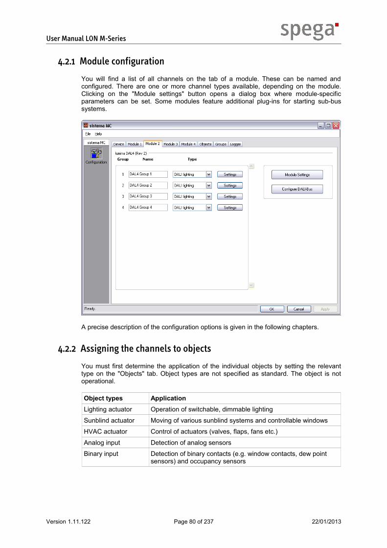
User Manual LON M-Series
4.2.1 Module configuration
You will find a list of all channels on the tab of a module. These can be named and configured. There are one or more channel types available, depending on the module. Clicking on the "Module settings" button opens a dialog box where module-specific parameters can be set. Some modules feature additional plug-ins for starting sub-bus systems.
A precise description of the configuration options is given in the following chapters.
4.2.2 Assigning the channels to objects
You must first determine the application of the individual objects by setting the relevant type on the "Objects" tab. Object types are not specified as standard. The object is not operational.
Object types ApplicationLighting actuator Operation of switchable, dimmable lighting
Sunblind actuator Moving of various sunblind systems and controllable windows
HVAC actuator Control of actuators (valves, flaps, fans etc.)
Analog input Detection of analog sensors
Binary input Detection of binary contacts (e.g. window contacts, dew point sensors) and occupancy sensors
Version 1.11.122 Page 80 of 237 22/01/2013

User Manual LON M-Series
The table shows which channel types can be activated or captured by the individual object types.
Channel types Object types
Ligh
ting
actu
ator
Sunb
lind
actu
ator
HVA
C a
ctua
tor
Anal
og in
put
Bin
ary
inpu
t
Switched load x
Dimmed lighting x
DALI lighting x
Shade x*
Awning x*
Blind x*
Blind 3 end positions x*
Window x*
Valve (constant) x
Valve (6-way) x
Valve (2-point) x
Valve (3-point) x
Fan (on/off) x
Version 1.11.122 Page 81 of 237 22/01/2013

User Manual LON M-Series
Channel types Object types
Ligh
ting
actu
ator
Sunb
lind
actu
ator
HVA
C a
ctua
tor
Anal
og in
put
Bin
ary
inpu
t
Fan (2-stage) x
Fan (3-stage) x
Analog input x
Digital input x * no mixed channels are allowed on the same object
The channels are assigned to objects by checking the boxes in the assignment matrix.
Once the changes made are accepted, the individual objects can be configured by clicking "Plug-in".
4.2.3 Configuring objects
Objects are configured via the object plug-ins, which can be run directly from the device plug-in on the "Objects" tab. Alternatively, the object plug-ins can also be started directly on the corresponding object in the LNS tool. A precise description of the setting options for the individual object types is given in the following chapters.
Version 1.11.122 Page 82 of 237 22/01/2013

User Manual LON M-Series
4.2.4 Creating and configuring groups
On the "Groups" tab you must first specify for which of the object types listed above the group is to be used. You can then stipulate the members of the group.
These can be run in the device plug-in on the "Groups" tab or in the LNS tool on the group objects. A precise description of the setting options for the individual group object types is given in the following chapters.
Version 1.11.122 Page 83 of 237 22/01/2013

User Manual LON M-Series
4.3. Module Configuration The application supports control of several module types. The setting of connected modules has to be done in the device plug-in, as described in the relevant section. Functionality and parametrization vary depending on module type.
4.3.1 clima AAx
The clima AA4 and clima AA8 actuator modules feature outputs for thermoelectric or motor-driven drives.
The following documentation is valid for modules with:
Revision 2Hardware version 001.000Firmware version 001.017
Modules
The modules listed are grouped under the module type clima AAx:
Module types Number of channelsclima AA4 (Rev 2) 4
clima AA8 (Rev 2) 8
Module parametrization
The module is parameterized in the device plug-in on the tab of the corresponding module. The module parameters can be accessed via the "Module settings" button.
Version 1.11.122 Page 84 of 237 22/01/2013

User Manual LON M-Series
Channel parametrization
A type must first be selected for each channel. Further settings can be made depending on the channel type.
Channel types
With the clima AAx-type modules there are 3 types of channel to choose from:
With 3-point valves two channels must be used. They can only be set on "uneven" channels and also uses the next channel up.
Settings
The available settings for the channel depend on the type.
Valve (2-point)This channel type is used for 2-point actuators and thermoelectric drives. For quasi-continuous control, pulse width modulation can be parameterized in the assigned HVAC object.
Version 1.11.122 Page 85 of 237 22/01/2013

User Manual LON M-Series
Valve (3-point)This channel type must be selected when connecting 3-point actuators.
Switched loadThis type may be used where a simple switched load is connected.
Version 1.11.122 Page 86 of 237 22/01/2013

User Manual LON M-Series
Copying parameters
Both module and channel parameters can be copied by means of the relevant dialog boxes using "OK + Transfer" to other compatible modules or channels of the same devices or other devices in the project. For details on copying parameters please see the section on "Copying configurations".
Replacing a module
To replace a module, you must first ensure that the combination of devices is de-energized and all connecting cables removed. Release the module from the combination of devices by pushing the modules apart. Replace it with a module of the same type and revision. Push the combined unit with the new module back together. Re-connect all cables and lines. Information on connecting and assembling the modules can be found in the section entitled "Product description".
Version 1.11.122 Page 87 of 237 22/01/2013

User Manual LON M-Series
4.3.2 clima AAx-10V
The clima AA4-10V and clima AA8-10V actuator modules can be used either as analog outputs for continuous drives or as analog inputs for active sensors.
The following documentation is valid for modules with:
Revision 2Hardware version 001.000Firmware version 002.001
Modules
The modules listed are grouped under the module type clima AAx-10V:
Module types Number of channelsclima AA4-10V (Rev 2) 4
clima AA8-10V (Rev 2) 8
Channel parametrization
A type must first be selected for each channel. Further settings can be made depending on the channel type.
Channel types
With the clima AAx-10V-type modules there are 4 types of channel to choose from:
Version 1.11.122 Page 88 of 237 22/01/2013

User Manual LON M-Series
Settings
The available settings for the channel depend on the type.
Valve (continuous)This type of channel is used for continuous actuators with linear control.
Version 1.11.122 Page 89 of 237 22/01/2013

User Manual LON M-Series
Valve (6-way)This type of channel is used for continuous actuators for controlling 6-way valves. Control is performed continuously within the configurable sequence limits. Within the assigned HVAC object both sequences are distinguished by the algebraic sign of the control value.
Version 1.11.122 Page 90 of 237 22/01/2013

User Manual LON M-Series
Analog inputThis channel type is used if analog sensors are connected.
Copying parameters
Both module and channel parameters can be copied by means of the relevant dialog boxes using "OK + Transfer" to other compatible modules or channels of the same devices or other devices in the project. For details on copying parameters please see the section on "Copying configurations".
Replacing a module
To replace a module, you must first ensure that the combination of devices is de-energized and all connecting cables removed. Release the module from the combination of devices by pushing the modules apart. Replace it with a module of the same type and revision. Push the combined unit with the new module back together. Re-connect all cables and lines. Information on connecting and assembling the modules can be found in the section entitled "Product description".
Version 1.11.122 Page 91 of 237 22/01/2013

User Manual LON M-Series
4.3.3 clima AAx-MP
The clima AA8-MP and clima AA4-MP actuator modules can activate MP bus devices and also pick up a directly connected sensor for each MP bus device.
The following documentation is valid for modules with:
Revision 1Hardware version 001.000Firmware version 002.000 or higher
Module
The modules listed are grouped under the module type clima AAx-MP:
Module type Number of MP-Bus membersclima AA4-MP (Rev 1) 4
clima AA8-MP (Rev 1) 8
Module parametrization
The module is parameterized in the device plug-in on the tab of the corresponding module. The module parameters can be accessed via the "Module settings" button.
Version 1.11.122 Page 92 of 237 22/01/2013

User Manual LON M-Series
Configuring the MP-Bus
You can start the configuration of the MP bus in the device plug-in on the tab of the corresponding module by clicking "Configure MP-Bus".
General
A brand new clima AA8-MP or clima AA4-MP module does not feature any configuration as standard. This means the list of MP bus devices is empty. To ensure connected devices can be controlled, they need to be made known to the module.
Adding MP-Bus devices
The MP bus devices to be controlled must have an MP bus address and be connected to the module. To add the connected devices to the list, click the "Search" button. The devices found are added to the list with their unique serial number and programmed information including "Name", "Where installed" and MP bus address. The devices must now be assigned a channel each. Click in the "Channel" column of the relevant device and select the desired channel. Click "Accept" to save the configuration.
Connected sensors
To be able to read in a sensor which is directly connected to an MP bus device, the sensor must be configured for this purpose. To do this, open the context menu by right-clicking the relevant device and select "Edit device". A new dialog box will open and you may select the corresponding sensor type.
Version 1.11.122 Page 93 of 237 22/01/2013

User Manual LON M-Series
MP-Bus device status display
The symbols in front of the individual MP bus devices show whether communication with the device concerned is possible. The display can be updated by clicking "Update". Please note that devices, once added, must first be made known to the module - by clicking "Accept" - before their status can be retrieved.
Removing MP-Bus devices
To remove a device from the configuration, click on the "Channel" column of the device concerned and set the channel to "None". Click "Accept" to save the configuration.
Channel parametrization
A type must first be selected for each channel. Further settings can be made depending on the channel type.
Channel types
With the clima AAx-MP module you can choose between 2 types of actuator channel ...
... and 2 types of sensor channel:
Version 1.11.122 Page 94 of 237 22/01/2013

User Manual LON M-Series
Settings
The available settings for the channel depend on the type.
Valve (continuous)This type of channel is used for continuous actuators with linear control.
Valve (6-way)This type of channel is used for continuous actuators for controlling 6-way valves. Control is performed continuously within the configurable sequence limits. Within the assigned HVAC object both sequences are distinguished by the algebraic sign of the control value.
Version 1.11.122 Page 95 of 237 22/01/2013

User Manual LON M-Series
Analog inputThis channel type is used if analog sensors are connected. Detailed settings for the connected sensors have to be made in the MP-Bus plug-in.
Digital inputThe digital input channel type is used for simple binary contacts.
Copying parameters
Both module and channel parameters can be copied by means of the relevant dialog boxes using "OK + Transfer" to other compatible modules or channels of the same devices or other devices in the project. For details on copying parameters please see the section on "Copying configurations".
Replacing a module
During the MP bus configuration, the module configuration is also saved in the LNS project database (e.control Plug-ins V2.10 or higher). This allows a comfortable module replacement.
To replace a module, you must first ensure that the combination of devices is de-energized and all connecting cables removed. Release the module from the combination of devices by pushing the modules apart. Replace it with a module of the same type and revision. Push the combined unit with the new module back together. Re-connect all cables and lines. Information on connecting and assembling the modules can be found in the section entitled "Product description".
You can now run the MP bus configuration from the device plug-in. A module replacement is automatically detected by the configuration software. The saved configuration is stored in the new module. Now the MP bus is again ready for operation.
Backup and restore of the module configuration per file is also available.
Replacing a bus node
If an MP bus device needs to be replaced, the device in question must first be removed from the list before a new device is added. For further details refer to the sections entitled "Removing MP bus devices" and "Adding MP bus devices" in Chapter "Configuring the MP-bus".
Version 1.11.122 Page 96 of 237 22/01/2013

User Manual LON M-Series
Extended status feedback
Configured clima AAx-MP modules can detect states of MP-bus devices. The device management supports an output of these states via network variable. Following states can be detected:
Status Type of failureMP bus device reporting peripheral error peripheral failure on the sub-bus device
MP bus device reporting device failure sub-bus device failure
communication failure with the MP bus device
sub-bus device communication error
No MP bus power supply sub-bus device communication error
Version 1.11.122 Page 97 of 237 22/01/2013

User Manual LON M-Series
4.3.4 clima LA2-3
The clima LA2-3 multi-stage actuator features outputs for up to 3 switching stages.
The following documentation is valid for modules with:
Revision 1Hardware version 001.000Firmware version 001.017
Module
Module type Number of channelsclima LA2-3 (Rev 1) 2
Module parametrization
The module is parameterized in the device plug-in on the tab of the corresponding module. The module parameters can be accessed via the "Module settings" button.
Version 1.11.122 Page 98 of 237 22/01/2013

User Manual LON M-Series
Channel parametrization
A type must first be selected for each channel. Further settings can be made depending on the channel type.
Channel types
With the clima LA2-3-type modules there are 9 types of channel to choose from:
Settings
The available settings for the channel depend on the type.
Fan (on/off)This channel type is used for fans which are only switched on or off.
Version 1.11.122 Page 99 of 237 22/01/2013

User Manual LON M-Series
Fan (2-stage)This channel type is used for controlling fans with two switching stages.
Version 1.11.122 Page 100 of 237 22/01/2013

User Manual LON M-Series
Fan (3-stage)This channel type is used for controlling fans with three switching stages.
Version 1.11.122 Page 101 of 237 22/01/2013

User Manual LON M-Series
ShadeThis channel type is offered for controlling shades.
Version 1.11.122 Page 102 of 237 22/01/2013

User Manual LON M-Series
AwningThis channel type is provided for controlling awnings.
Version 1.11.122 Page 103 of 237 22/01/2013

User Manual LON M-Series
BlindThis channel type is offered for controlling blinds.
Version 1.11.122 Page 104 of 237 22/01/2013

User Manual LON M-Series
Blind, 3 end positionsThis channel type should be used for sunblinds with 3 end positions.
Version 1.11.122 Page 105 of 237 22/01/2013

User Manual LON M-Series
WindowWindows are controlled using this channel type.
Switched loadThis type may be used where a simple switched load is connected.
Version 1.11.122 Page 106 of 237 22/01/2013

User Manual LON M-Series
Copying parameters
Both module and channel parameters can be copied by means of the relevant dialog boxes using "OK + Transfer" to other compatible modules or channels of the same devices or other devices in the project. For details on copying parameters please see the section on "Copying configurations".
Replacing a module
To replace a module, you must first ensure that the combination of devices is de-energized and all connecting cables removed. Release the module from the combination of devices by pushing the modules apart. Replace it with a module of the same type and revision. Push the combined unit with the new module back together. Re-connect all cables and lines. Information on connecting and assembling the modules can be found in the section entitled "Product description".
Version 1.11.122 Page 107 of 237 22/01/2013

User Manual LON M-Series
4.3.5 lumina BE8
The lumina BE8 binary input module is used to capture floating contacts, such as window contacts and dew point or occupancy sensors.
The following documentation is valid for modules with:
Revision 2Hardware version 001.001Firmware version 002.002
Module
Module type Number of channelslumina BE8 (Rev 2) 8
Channel parametrization
A type must first be selected for each channel. Further settings can be made depending on the channel type.
Channel types
Only the digital input can be selected as a channel type for the lumina BE8 module.
Settings
The digital input channel type is used for simple binary contacts.
Version 1.11.122 Page 108 of 237 22/01/2013

User Manual LON M-Series
Copying parameters
Both module and channel parameters can be copied by means of the relevant dialog boxes using "OK + Transfer" to other compatible modules or channels of the same devices or other devices in the project. For details on copying parameters please see the section on "Copying configurations".
Replacing a module
To replace a module, you must first ensure that the combination of devices is de-energized and all connecting cables removed. Release the module from the combination of devices by pushing the modules apart. Replace it with a module of the same type and revision. Push the combined unit with the new module back together. Re-connect all cables and lines. Information on connecting and assembling the modules can be found in the section entitled "Product description".
Version 1.11.122 Page 109 of 237 22/01/2013

User Manual LON M-Series
4.3.6 lumina DALx
The lumina DAL4, lumina DAL8 and lumina DAL16 lighting actuator modules are used to activate up to 64 DALI devices in groups.
The following documentation is valid for modules with:
Revision 2Hardware version 001.000 or higherFirmware version 002.003 or higher
Modules
The modules listed are grouped under the module type lumina DALx:
Module types Number of groupslumina DAL4 (Rev 2) 4
lumina DAL8 (Rev 2) 8
lumina DAL16 (Rev 2) 16
Module parametrization
The module is parameterized in the device plug-in on the tab of the corresponding module. The module parameters can be accessed via the "Module settings" button.
This setting is particularly important when using an emergency power system.
Version 1.11.122 Page 110 of 237 22/01/2013

User Manual LON M-Series
Configuring the DALI-Bus
You can start the configuration of the DALI bus in the device plug-in on the tab of the corresponding module by clicking "Configure DALI-Bus".
System
Here you can set the DALI bus power supply. Select "internal" and the lumina DALx module will take over the power supply. If an external electricity supply is installed, the lumina DALx module supply must not be active. To do this set the value to "external". The "auto" setting should only be selected temporarily if you are unsure whether an external power supply has been installed.
Version 1.11.122 Page 111 of 237 22/01/2013

User Manual LON M-Series
Naming DALI groups
This is where you can give the DALI groups corresponding names.
DALI devices
This is where the DALI devices are configured.
Version 1.11.122 Page 112 of 237 22/01/2013

User Manual LON M-Series
General
A brand new lumina DALx module does not feature any configuration as standard. This means the list of DALI devices is empty. To ensure connected devices can be controlled, they need to be made known to the module.
Adding DALI bus devices
The DALI bus devices to be controlled must be connected to the module. To add the connected devices to the list, click the "Search" button. Any devices found will be added to the list.
Assignment to DALI groups
The devices must now be assigned a DALI group each. Click in the "DALI group" column of the relevant device and select the desired group. For the purpose of identifying the individual DALI devices, click the light symbol in the line of the corresponding device. Flashing of the relevant light is switched on or off in this way. Alternatively, you may use the group assistant to assign the groups; this helps to simplify work in installations with a large number of DALI stations. Click "Group assistant" and follow the instructions. Click "Accept" to save the configuration.
Light status display
The individual DALI device symbols show whether communication with the relevant device is taking place and whether the device is showing an error. The display can be updated by clicking "Update". Please note that DALI devices, once added, must first be made known to the module - by clicking "Accept" - before their status can be retrieved.
Version 1.11.122 Page 113 of 237 22/01/2013

User Manual LON M-Series
Group parametrization
The group parametrization function is reached by selecting the "Settings" button. A type must first be assigned to each group, after which specific settings can be made.
Group type
With the lumina DALx-type module only DALI lighting can be selected as a type.
Settings
The DALI lighting group type is used for DALI ballasts.
Copying parameters
Both module and channel parameters can be copied by means of the relevant dialog boxes using "OK + Transfer" to other compatible modules or channels of the same devices or other devices in the project. For details on copying parameters please see the section on "Copying configurations".
Saving and loading configurations
The DALI bus configuration can be saved in a file in the plug-in and restore from the file. In this way modules can be replaced without the need for lengthy reconfiguration.
Version 1.11.122 Page 114 of 237 22/01/2013

User Manual LON M-Series
Replacing a module
When the DALI module is configured via RS232, you should save the configuration in a file, if you have not already done so, before replacing the module.
During the configuration via LON, the module configuration is also saved in the LNS project database (e.control Plug-ins V2.10 or higher), so that a backup in a file is no longer necessary. This allows a comfortable module replacement.
To replace a module, you must first ensure that the combination of devices is de-energized and all connecting cables removed. Release the module from the combination of devices by pushing the modules apart. Replace it with a module of the same type and revision. Push the combined unit with the new module back together. Re-connect all cables and lines. Information on connecting and assembling the modules can be found in the section entitled "Product description".
You can now run the DALI bus configuration from the device plug-in. On configuration via RS232 load the saved configuration file in the plug-in and accept the settings.
On configuration via LON a module replacement is automatically detected by the configuration software. The saved configuration is stored in the new module. Now the DALI bus is again ready for operation.
Replacing a bus node
If a DALI bus device needs to be replaced, the device in question must first be removed from the list before a new device is added. For further details refer to the sections entitled "Removing MP bus devices" and "Adding DALI bus devices" in Chapter "Configuring the DALI bus".
Extended status feedback
Configured lumina DALx modules can detect DALI device status and lamp status. The device management supports an output of these states via network variable. Usually the lamp status can only detected and reported by the DALI ballast if it has received a switch-on command. This also applies on tacking back failures. Following states can be detected:
Status type of failureDALI device reporting lamp failure peripheral failure on the sub-bus device
DALI device reporting device failure sub-bus device failure
DALI device is offline sub-bus device communication error
No DALI power supply or short circuit on DALI-bus
sub-bus device communication error
Version 1.11.122 Page 115 of 237 22/01/2013

User Manual LON M-Series
4.3.7 lumina SAx
The lumina SA4 and lumina SA8 switch actuator modules are used for activating electrical consumers.
The following documentation is valid for modules with:
Revision 2Hardware version 001.000Firmware version 001.017
Modules
The modules listed are grouped under the module type lumina SAx:
Module types Number of channelslumina SA4 (Rev 2) 4
lumina SA8 (Rev 2) 8
Module parametrization
The module is parameterized in the device plug-in on the tab of the corresponding module. The module parameters can be accessed via the "Module settings" button.
Version 1.11.122 Page 116 of 237 22/01/2013

User Manual LON M-Series
Channel parametrization
A type must first be selected for each channel. Further settings can be made depending on the channel type.
Channel types
With the lumina SAx-type modules there are 3 types of channel to choose from:
With 3-point valves two channels must be used. They can only be set on "uneven" channels and also uses the next channel up.
Settings
The available settings for the channel depend on the type.
Switched loadThis type may be used where a simple switched load is connected.
Version 1.11.122 Page 117 of 237 22/01/2013

User Manual LON M-Series
Valve (2-point)This channel type is used for 2-point actuators and thermoelectric drives. For quasi-continuous control, pulse width modulation can be parameterized in the assigned HVAC object.
Valve (3-point)This channel type must be selected when connecting 3-point actuators.
Version 1.11.122 Page 118 of 237 22/01/2013

User Manual LON M-Series
Copying parameters
Both module and channel parameters can be copied by means of the relevant dialog boxes using "OK + Transfer" to other compatible modules or channels of the same devices or other devices in the project. For details on copying parameters please see the section on "Copying configurations".
Replacing a module
To replace a module, you must first ensure that the combination of devices is de-energized and all connecting cables removed. Release the module from the combination of devices by pushing the modules apart. Replace it with a module of the same type and revision. Push the combined unit with the new module back together. Re-connect all cables and lines. Information on connecting and assembling the modules can be found in the section entitled "Product description".
Version 1.11.122 Page 119 of 237 22/01/2013

User Manual LON M-Series
4.3.8 lumina ST4
The lumina ST4 lighting actuator module is used to activate electronic ballasts with a 1-10V interface.
The following documentation is valid for modules with:
Revision 2Hardware version 001.000Firmware version 005.003
Module
Module types Number of channelslumina ST4 (Rev 2) 4
Module parametrization
The module is parameterized in the device plug-in on the tab of the corresponding module. The module parameters can be accessed via the "Module settings" button.
Version 1.11.122 Page 120 of 237 22/01/2013

User Manual LON M-Series
Channel parametrization
A type must first be selected for each channel. Further settings can be made depending on the channel type.
Channel types
Only dimmed lighting can be selected as a channel type for the lumina ST4 module.
Settings
The dimmed lighting channel type is used for activating dimmable ballasts.
Copying parameters
Both module and channel parameters can be copied by means of the relevant dialog boxes using "OK + Transfer" to other compatible modules or channels of the same devices or other devices in the project. For details on copying parameters please see the section on "Copying configurations".
Replacing a module
To replace a module, you must first ensure that the combination of devices is de-energized and all connecting cables removed. Release the module from the combination of devices by pushing the modules apart. Replace it with a module of the same type and revision. Push the combined unit with the new module back together. Re-connect all cables and lines. Information on connecting and assembling the modules can be found in the section entitled "Product description".
Version 1.11.122 Page 121 of 237 22/01/2013

User Manual LON M-Series
4.3.9 ombra BAx
The ombra BA2, ombra BA4 and ombra BA4-DC sunblind actuator modules feature mutually interlocked connections for controlling sunblind motors.
The following documentation is valid for modules with:
Revision 2Hardware version 001.000Firmware version 001.017
Modules
The modules listed are grouped under the module type ombra BAx:
Module types Number of channelsombra BA2 (Rev 2) 2
ombra BA4 (Rev 2) 4
ombra BA4-DC (Rev 2) 4
Module parametrization
The module is parameterized in the device plug-in on the tab of the corresponding module. The module parameters can be accessed via the "Module settings" button.
Version 1.11.122 Page 122 of 237 22/01/2013

User Manual LON M-Series
Channel parametrization
A type must first be selected for each channel. Further settings can be made depending on the channel type.
Channel types
With the ombra BAx-type modules there are 7 types of channel to choose from:
Settings
The available settings for the channel depend on the type.
Version 1.11.122 Page 123 of 237 22/01/2013
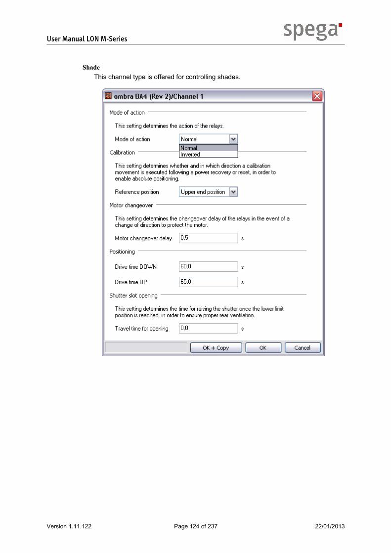
User Manual LON M-Series
ShadeThis channel type is offered for controlling shades.
Version 1.11.122 Page 124 of 237 22/01/2013

User Manual LON M-Series
AwningThis channel type is provided for controlling awnings.
Version 1.11.122 Page 125 of 237 22/01/2013

User Manual LON M-Series
BlindThis channel type is offered for controlling blinds.
Version 1.11.122 Page 126 of 237 22/01/2013

User Manual LON M-Series
WindowWindows are controlled using this channel type.
Switched loadThis type may be used where a simple switched load is connected.
Version 1.11.122 Page 127 of 237 22/01/2013

User Manual LON M-Series
Fan (on/off)This channel type is used for fans which are only switched on or off.
Fan (2-stage)This channel type is used for controlling fans with two switching stages.
Version 1.11.122 Page 128 of 237 22/01/2013

User Manual LON M-Series
Copying parameters
Both module and channel parameters can be copied by means of the relevant dialog boxes using "OK + Transfer" to other compatible modules or channels of the same devices or other devices in the project. For details on copying parameters please see the section on "Copying configurations".
Replacing a module
To replace a module, you must first ensure that the combination of devices is de-energized and all connecting cables removed. Release the module from the combination of devices by pushing the modules apart. Replace it with a module of the same type and revision. Push the combined unit with the new module back together. Re-connect all cables and lines. Information on connecting and assembling the modules can be found in the section entitled "Product description".
Version 1.11.122 Page 129 of 237 22/01/2013

User Manual LON M-Series
4.3.10 ombra BA2-3E
The ombra BA2-3E sunblind actuator is used to control sunblind motors with 3 end positions.
The following documentation is valid for modules with:
Revision 2Hardware version 001.000Firmware version 001.017
Module
Module types Number of channelsombra BA2-E (Rev 2) 2
Module parametrization
The module is parameterized in the device plug-in on the tab of the corresponding module. The module parameters can be accessed via the "Module settings" button.
Channel parametrization
A type must first be selected for each channel. Further settings can be made depending on the channel type.
Version 1.11.122 Page 130 of 237 22/01/2013

User Manual LON M-Series
Channel types
With the ombra BA2-3E module there are 9 types of channel to choose from:
Settings
The available settings for the channel depend on the type.
Version 1.11.122 Page 131 of 237 22/01/2013

User Manual LON M-Series
ShadeThis channel type is offered for controlling shades.
Version 1.11.122 Page 132 of 237 22/01/2013

User Manual LON M-Series
AwningThis channel type is provided for controlling awnings.
Version 1.11.122 Page 133 of 237 22/01/2013

User Manual LON M-Series
BlindThis channel type is offered for controlling blinds.
Version 1.11.122 Page 134 of 237 22/01/2013

User Manual LON M-Series
Blind, 3 end positionsThis channel type should be used for sunblinds with 3 end positions.
Version 1.11.122 Page 135 of 237 22/01/2013

User Manual LON M-Series
WindowWindows are controlled using this channel type.
Switched loadThis type may be used where a simple switched load is connected.
Fan (on/off)This channel type is used for fans which are only switched on or off.
Version 1.11.122 Page 136 of 237 22/01/2013

User Manual LON M-Series
Fan (2-stage)This channel type is used for controlling fans with two switching stages.
Version 1.11.122 Page 137 of 237 22/01/2013

User Manual LON M-Series
Fan (3-stage)This channel type is used for controlling fans with three switching stages.
Copying parameters
Both module and channel parameters can be copied by means of the relevant dialog boxes using "OK + Transfer" to other compatible modules or channels of the same devices or other devices in the project. For details on copying parameters please see the section on "Copying configurations".
Replacing a module
To replace a module, you must first ensure that the combination of devices is de-energized and all connecting cables removed. Release the module from the combination of devices by pushing the modules apart. Replace it with a module of the same type and revision. Push the combined unit with the new module back together. Re-connect all cables and lines. Information on connecting and assembling the modules can be found in the section entitled "Product description".
Version 1.11.122 Page 138 of 237 22/01/2013

User Manual LON M-Series
4.3.11 ombra BAx-SMI
The ombra BA4-SMI, ombra BA8-SMI and ombra BA16-SMI blind actuator modules are used to activate up to 16 SMI motors.
The following documentation is valid for modules with:
Revision 2Hardware version 001.000Firmware version 002.000 or higher
Modules
The modules listed are grouped under the module type ombra BAx-SMI:
Module types Number of groups Adressing modeombra BA4-SMI (Rev 2) 4 group adressing
ombra BA8-SMI (Rev 2) 8 single adresssing
ombra BA16-SMI (Rev 2) 16 single adressing
Module parametrization
The module is parameterized in the device plug-in on the tab of the corresponding module. The module parameters can be accessed via the "Module settings" button.
Version 1.11.122 Page 139 of 237 22/01/2013

User Manual LON M-Series
Configuring the SMI-Bus
You can start the configuration of the SMI bus in the device plug-in on the tab of the corresponding module by clicking "Configure SMI bus". This is only required for SMI modules which use single addressing.
General
A brand new ombra BAx-SMI module does not feature any configuration as standard. This means the list of SMI motors is empty. To ensure connected motors can be controlled, they need to be made known to the module. This can be done in two ways.
Adding motors
If the motors to be controlled are connected to the module, click the "Search" button. Any motors founds will be added to the list with their unique serial numbers. If the motors to be controlled are not connected to the module, you can select "Add motor" in the context menu by right-clicking the list. A dialog box will appear in which you can enter the serial number of the desired motor. Click "Accept" to save the motor data entered or found.
Assignment to SMI groups
To assign the motors to individual SMI groups, click in the "Group" column of the motor in question and select the desired group number. Select "Edit motor" in the context menu to identify the individual motors. The next dialog box to open will allow you to operate the motor.
Version 1.11.122 Page 140 of 237 22/01/2013

User Manual LON M-Series
Motor status display
The symbols in front of the individual motors show whether communication with the motor concerned is possible. The display can be updated by clicking "Update". Please note that motors, once added, must first be made known to the module - by clicking "Accept" - before their status can be retrieved.
"Channel" column
The "Channel" column shows the physical channel of the module to which a motor is connected. This channel has nothing in common with the channel in the device plug-in.
Removing motors
To delete motors from the configuration, open the context menu on the motor concerned and select "Remove motor". Click "Accept" to save the list of motors displayed.
Channel/Group parametrization
The channel parametrization function is reached by selecting the "Settings" button. A type must first be assigned to each channel, after which specific settings can be made.
With SMI modules which use single addressing, it is called “group” instead of “channel”. Afterwards the term “channel” is used.
Channel/Group types
With the ombra BAx-SMI-type modules there are 3 types of channel to choose from:
Version 1.11.122 Page 141 of 237 22/01/2013

User Manual LON M-Series
Settings
Additional properties, which are adjustable on the channel, are only required for the 'blind' channel type.
To ensure the slat angle is positioned as precisely as possible, physical properties for the blind used must be entered here. As these values are difficult to ascertain, an assistant function is provided to give you the best possible guidance. To run the assistant, select "Find with assistant" and click "Start assistant". Follow the instructions on the assistant screen.
Note: Further parameters for the blind used which are also required for precise control must be set in the plug-in of the assigned object.
Copying parameters
Both module and channel parameters can be copied by means of the relevant dialog boxes using "OK + Transfer" to other compatible modules or channels of the same devices or other devices in the project. For details on copying parameters please see the section on "Copying configurations".
Version 1.11.122 Page 142 of 237 22/01/2013

User Manual LON M-Series
Replacing a module
During the SMI configuration, the module configuration is also saved in the LNS project database (e.control Plug-ins V2.10 or higher). This allows a comfortable module replacement.
To replace a module, you must first ensure that the combination of devices is de-energized and all connecting cables removed. Release the module from the combination of devices by pushing the modules apart. Replace it with a module of the same type and revision. Push the combined unit with the new module back together. Re-connect all cables and lines. Information on connecting and assembling the modules can be found in the section entitled "Product description".
You can now run the SMI configuration from the device plug-in. A module replacement is automatically detected by the configuration software. The saved configuration is stored in the new module. Now the SMI bus is again ready for operation.
Backup and restore of the module configuration per file is also available.
Replacing a bus node
If an SMI motor needs to be replaced, the motor in question must first be removed from the list before a new motor is added. For further details refer to the sections entitled "Removing motors" and "Adding motors" in Chapter "Configuring the SMI bus".
Extended status feedback
Configured ombra BAx-SMI modules can detect states of MP-bus devices. The device management supports an output of these states via network variable. Following states can be detected:
Status Type of failureSMI motor reporting failure sub-bus device failure
No assigned SMI motor found sub-bus device communication error
An already configured motor could not be found
sub-bus device communication error
short circuit on SMI bus or module mains voltage failure
sub-bus device communication error*
Version 1.11.122 Page 143 of 237 22/01/2013

User Manual LON M-Series
4.4. Object configurationThe applications provide universal objects. The type of each object as to be set in the device plug-in as described in the relevant section. According to the usage of the objects the functionality and parametrization vary. A detailed description of the various object types gives the following section.
4.4.1 Lamp actuator
The lamp actuator is used to activate switching and dimming actuators and can be adapted as required by parameterizing the object functions. Depending on the application version, the actuator object provides one or two network input variables, which are used to activate the actuator. The use of group objects means that additional input variables are available for central functions. Furthermore, each object sends back the current status of the actuator on its network output variable.
Overview of object functions
Extended functions are supported in addition to the VDI 3813-compliant room automation functions.
VDI3813 – Functions
• Light actuator• Space usage selection• Light switch• Stairwell lighting• Priority evaluation• Sequence control• Output range control
Extended function
• Switchable network variable types• Output network variable transmission response• Action in the event of communication faults• Action following resumption of power supply/reset• Activation via groups
It should be noted that the light switch and stairwell lighting functions cannot be used together.
Parametrization of object functions
The objects are parameterized using the corresponding object plug-ins. These can be started directly on the object from the device plug-in or in the LNS tool.
Action following resumption of power supply or reset
The response following the resumption of a power supply or RESET can be parameterized. Here either a status for switching actuators or a precise light value for
Version 1.11.122 Page 144 of 237 22/01/2013

User Manual LON M-Series
dimming actuators can be specified. You can also specify that no command should be executed. Parametrization is carried out in the object plug-in on the "General" tab.
Depending on the hardware activated the actuator's light value definition function can be deactivated until the actuator has received and executed a new light value. If the light value cannot be determined correctly, the output network variable will send back an invalid value.
Light actuator
The actuator object can activate both switching and dimming actuators. Control output values are set as follows, depending on the type of NV and actuator:
SNVT_setting SNVT_switch Switching actuator
Dimming actuator
(SET_OFF, x, y) (x, 0) OFF OFF
(SET_ON, 0.0, y) (0, 1) OFF OFF
(SET_ON, x > 0, y) (x > 0, 1) ON Light value x
(SET_DOWN, x, y) (x, 2) - Dim down by x (no switch-off)
(SET_UP, x, y) (x, 3) - Dim up by x (no switch-on)
(SET_STOP, x, y) (x, 4) - Stops the dimming process
(SET_STATE, 0.0, y) (0, 5) OFF OFF
(SET_STATE, x > 0, y) (x > 0, 5) ON Light value x
With dimming actuators the dimming response can be adjusted as required by varying the fade time. Parametrization is carried out in the object plug-in on the "Dimming" tab.
The fade time determines the duration of the dimming process from the current light value to the next light value requested. It is independent of the difference between the light values.
Version 1.11.122 Page 145 of 237 22/01/2013

User Manual LON M-Series
Light switch
To implement light switch functions which comply with VDI 3813, separate time delays for switching-on and switching-off procedures can be specified. In addition, it is possible to specify for each priority used for priority control whether the switching-on and switching-off delays should be taken into account. This setting can be made in the object plug-in on the "Delays" tab.
You can activate the delay function by selecting a priority. If no priority is selected, the delays will not be activated. Please note that delays and stairwell lighting cannot be used together.
Stairwell lighting
The lighting actuator can be used for stairwell lighting complying with VDI 3813. In stairwell lighting mode the actuator automatically switches off the lighting once the parameterizable lighting duration has elapsed. Where configured, the stairwell lighting duration is followed by a warning period which provides information that the lighting is about to be switched off. Here dimming actuators change alter their light value during the warning period to a warning light value and switching actuators flash at the set warning intervals. In cases where the premature switch-off function is used, the actuator is switched off prematurely as soon as a switch-off command is received. Switch-off commands are otherwise ignored. If the lighting duration can be extended, an active stairwell lighting period is re-started when a switch-on command is received. In addition, it is possible to specify for each priority used for priority control whether the stairwell lighting switch is used. Parametrization of the stairwell lighting is carried out in the object plug-in on the "Stairwell lighting" tab.
Version 1.11.122 Page 146 of 237 22/01/2013

User Manual LON M-Series
You can activate the stairwell lighting function by selecting a priority. If no priority is selected, the stairwell lighting function will not be activated. Please note that the stairwell lighting and light switch functions cannot be used together.
Priority evaluation
The object is activated via the input network variables. By setting priorities various input variables can be sorted according to their importance. In this way mutual interference caused by activation from more than one source can be avoided. Priority evaluation is parameterized via the object plug-in. If group objects are used as control sources, parts of the priority evaluation must also be set here in the relevant object plug-in.
Principle of operationEach priority has two initial states. Either valid activation values are received, in which case the priority is considered active, or the activity is explicitly retracted, whereby an 'invalid' value is sent.
Version 1.11.122 Page 147 of 237 22/01/2013

User Manual LON M-Series
PRI_1inactiv
PRI_1activ + valid
activation command / value
priority reset
activation command or
value
process value
In the case of a single priority the status diagram shown above applies. As soon as other priorities are added they must be mutually interlocked.
PRI_1inactiv
PRI_1activ + valid
PRI_1activ
Higher PRIO activ?
activation command / value
No
PRI_2inactiv
PRI_2activ + valid
PRI_2activ
Higher PRIO activ?
No
PRI_3inactiv
PRI_3activ + valid
PRI_3activ
Higher PRIO activ?
No
A2
A2
A3
A3
priority reset
activation command or
value
process value
A3priority reset
priority reset
B2
B3
B3
B2 B3 Yes
Yes
Yes
restore
C1
C1*
activation command / value
restore
C2
activation command / value
C1* C2*
As a result each priority is given a further status. It may now be active, however its values may not be executed due to a higher-weighted priority. It loses its validity as soon as a higher priority is activated (Ax events). On the other hand, a priority may regain its validity as soon as the last higher priority is retracted (Bx events) or it replaces higher priorities itself (Cx events). In cases where a priority becomes valid again because a higher priority has been retracted, it is possible to stipulate for the re-validated priority how it should handle this event.
ParametrizationA full overview of the room and central functions in which the lighting actuator is involved is vital for setting the priority evaluation parameters. For this reason the configuration stages are described using an example.
Version 1.11.122 Page 148 of 237 22/01/2013

User Manual LON M-Series
Example A light switch linked to a motion sensor is to be implemented in an office, with manual operation of the lighting also enabled. A manually reduced light value must not be reset by any new motion which is sensed. However the lighting must also switch itself off even after manual operation, if it can be assumed that there is no longer anyone present in the room.
Step 1 – Selection of input variables1 or 2 input network variables are available on the object, depending on the application. Group objects may also be used for other input variables. The inputs on the object are best suited for local functions and groups are suitable for central functions.
Example In our example both functions can be considered as a local function, such that the 2 input network variables can be used where available. If only 1 input variable is present, it is recommended that a group object is used for the stairwell lighting.
Step 2 – Selection of prioritiesHere you must first consider which priorities are suitable for implementing the functions. In total there are 6 different priorities available with the following weighting:
Automatic < Manual < Override 1 < Weather < Override 2 < Safety
Example In our example the 'Automatic' priority is suitable for the stairwell lighting and 'Manual' for manual operation.
The priority is set on the respective input network variable used, this also affects activation via groups (see section on groups). The priority can be set in the object plug-in on the tab of the corresponding input variable in the section entitled "Priority".
Step 3 – Defining the type of activationThere are 3 types of activation for each input network variable. This determines how the commands received are processed.
Setting MeaningExecute received command Each telegram on the input variable is set directly as a
new light value.
On switch-on command If a switch-on command is received, the command specified is executed. A switch-off command causes the priority to be retracted.
Version 1.11.122 Page 149 of 237 22/01/2013

User Manual LON M-Series
Setting MeaningOn switch-off command If a switch-off command is received, the command
specified is executed. A switch-on command causes the priority to be retracted.
The "On switch-on command" and "On switch-off command" types of activation use the following switch-on and switch-off commands, depending on the type of network variable used:
NV type Switch-on command Switch-off commandSNVT_switch (100.0,1) (0.0,0)
SNVT_setting (SET_ON,100.0,0.00) (SET_OFF,0.0,0.00)
On activating the priority, a series of different commands can be selected for the "On switch-on command" and "On switch-off command" types of activation, whereby those commands not listed are not relevant for the lamp actuator.
Command MeaningNo command The priority is activated, however no command is executed
Off/close Switches off the lighting
On/open Switches on the lighting
Example In our example we are using the "Execute received command" type of activation for both the light switch and manual operation. This allows us to stipulate that the object is activated with direct light values or dimming commands.
The type of activation is defined separately for each input network variable; this also relates to groups (see section on groups). It is set in the object plug-in on the tab of the corresponding input variable in the section entitled "Priority".
Step 4 – How is the activity of the priorities reset?Priorities are usually reset via direct telegrams; here the corresponding invalid value should be sent, depending on the type of NV set. With the "On switch-on command" type of activation, switching-off causes the priority to be reset. The same applies when switching on using the "On switch-off command" type of activation. The invalid values for various types of NV are shown in the table:
NV type Invalid valueSNVT_switch (x, -1) any values are possible for x
Version 1.11.122 Page 150 of 237 22/01/2013

User Manual LON M-Series
NV type Invalid valueSNVT_setting (SET_NUL, x, y) any values are possible for x and y
SNVT_scene The scene input called up must contain an invalid value (see section on scene control)
Example In this example no cancellation is required for the light switch, as this is already the lowest priority value. However we cannot cancel manual operation by standard means, therefore another solution is required.
If an activation source is not able to trigger a cancellation directly from an invalid value (e.g. manual operation), there are 2 mechanisms available for switching the priority off again. Both alternatives are also available when using groups.
Alternative 1 – Automatic priority cancellation
First of all, a period of validity can be specified on the corresponding input network variable. If the specified time elapses without new, valid control output values being received, this event is treated as though an invalid value for cancellation had been received. This invalid value must therefore be explicitly specified below the relevant input network variable. For using the automatic priority cancellation the corresponding network variable has to be bound.
Example This is the most suitable alternative for resetting manual operation. In this way we can stipulate how long a manual override remains valid.
Automatic priority cancellation is set in the object plug-in on the "NVI settings" tab in the section entitled "Heartbeat monitoring". It should be noted that this function cannot be used at the same time as the treatment of communications faults on the same input variable.
Automatic priority cancellation is activated by selecting "invalid after" and entering the desired period of validity. "Invalid" should be selected as a value in order to ensure cancellation of the priority on expiry of the period of validity.
Alternative 2 – Priority restore
The second mechanism allows an active though invalid priority to try to restore its validity by deactivating higher priorities by means of a special command.
Example In our example no priority restoration is required.
Version 1.11.122 Page 151 of 237 22/01/2013

User Manual LON M-Series
The restore mechanism applies across all objects for all network inputs with the same priority (even if on a group) and is configured in the object plug-in on the "Priority settings" tab in the section entitled "Restore behaviour".
For each of the possible priorities you must first enter which of the higher priorities it can reset. If at least one priority is selected, the command must also be given as to which priority should initiate the reset. If this command is then received on the desired low priority, active priorities which are marked as resettable are reset. A priority reset can only be successfully implemented if no higher priorities are active after it. It should be noted that the return behaviour described below does not apply after a priority restoration.
Step 5 – Defining the return behaviourThe return behaviour describes what happens for each priority when it is reactivated because one/all higher priorities has/have been cancelled. You can choose between 3 different reactions for this object-wide setting:
Reaction DescriptionNone The system waits until a new operating command is received which is
then set normally.
Last abs. command
The last operating command received (absolute) is executed. Operating commands which were received when the priority was still active but invalid are also taken into account here.
Command A specific command is executed
It should be noted that the response following a reset (see previous section) cannot be specified, it always corresponds to the reaction "none". To execute a specific command it is possible to choose between the commands listed, depending on the type of NV, whereby those commands not listed are not relevant for the lamp actuator.
Command SNVT_switch SNVT_settingNo command (127.5, -1) (SET_NUL, 127.5, 655.34)
Off/close (0.0, 0) (SET_OFF, 0.0, 0.00)
On/open (100.0, 1) (SET_ON, 100.0, 0.00)
Version 1.11.122 Page 152 of 237 22/01/2013

User Manual LON M-Series
If the NV type SNVT_scene is present, the scene entry called up must contain the corresponding value. The desired response can be specified in the object plug-in on the "Priority settings" in the section entitled "Return behaviour".
The reaction is set for each priority under "Execute" when the priority is restored. If required the command to be executed must also be selected.
Example In the example the last absolute command is executed on return to 'Automatic'. Therefore the switch-off delay for the light switch starts directly if the room is no longer occupied.
Step 6 – Response following power resumption and RESETIf required, the activity of individual priorities can also be maintained beyond a RESET. In such cases this also influences the response following a RESET. For each priority a non-volatile memory has been set, it will be evaluated after a RESET or power resumption, if the priority was active before it. In this case the priority will be reactivated. Is one of the these priorities the valid priority after the evaluation, a configured positioning calibration (channel configuration) or a configured treatment on RESET (object configuration) will not be executed. If there is no active priority present, the parameterized treatment is executed following power resumption / reset.
Example Saving beyond a reset is not required for our example.
If priorities are to be retained beyond a reset, this can be configured on the "Save priority" tab.
Version 1.11.122 Page 153 of 237 22/01/2013

User Manual LON M-Series
Use of groups
Group objects for controlling the lamp actuators can be used. These are located on the same device and provide a network variable as an interface to all its group members. The ability to operate all output objects via a group object too means that central commands can be set up in such a way that only one network variable has to be bound for each device. Therefore, no alias table entries are used on the transmitting device, which would be required for binding the actuator objects separately.
The assignment of actuator objects to group objects has to be done in the device plug-in, as described in the relevant section. Operation of the group controllers and their parametrization are described in the section on the group objects.
Switchable network variables
Various types of network variable can be used for the lamp actuator. In this way, the object can be adapted to the network interfaces available in the network.. For some functions the respective type of NV is relevant when setting the parameters, for example in the case of priority evaluation. The standard types listed may be used:
NV types allowed for input variables allowed for output variablesSNVT_setting x -
SNVT_switch x x
SNVT_scene x -
The NV type is set in the object plug-in - for input variables this is done on the "NVI settings" tab in the section entitled "Input network variable", and for output variables on the "NVO settings" tab in the section "Output network variables".
Space usage selection (scene control)
A scene controller is available for the lamp actuator, allowing it to be activated via scenes. For this the network variable provided for activation purposes should set to 'SNVT_scene'. Telegrams on the input variable are processed as follows:
SNVT_scene MeaningSC_LEARN, x Save output variable as a control value for scene x
SC_RECALL, x Call up scene x
The scene plug-in for parameterizing the scene controller is run directly on the lamp actuator.
Version 1.11.122 Page 154 of 237 22/01/2013

User Manual LON M-Series
The scene controller contains a fixed number of entries, whereby the scene number of the first entry may be parameterized. All other entries have ascending numbers, as can be seen in column "No." Each entry to be used must first be activated in the column "Active". The scene entries are of type 'SNVT_switch' for the lamp actuator.
Action in the event of communication faults
Faulty input telegrams (see LonMark specifications) are ignored. In order to deal with communication faults and a related possible failure of individual activation sources, an input test can be set for each input network variable. For this the activation source must support cyclic transmission and its parameters be set accordingly. If no new network telegram is received within a parameterized time period, a previously defined command is executed. This may be used for activating or deactivating the relevant priority or may contain a specific lamp value.
It should be noted that this function cannot be used at the same time as automatic priority cancellation on the same input variable. Parametrization of the input test is performed for the input variable concerned in the object plug-in on the "NVI settings" tab in the section entitled "Heartbeat monitoring".
Version 1.11.122 Page 155 of 237 22/01/2013

User Manual LON M-Series
The input test is activated by selecting "invalid after" and entering the desired monitoring time. In addition, a value should be selected which is executed on expiry of the monitoring time, if no new telegram is received. You can choose between the values listed and the setting "User-defined".
Entry SNVT_switch SNVT_setting MeaningSwitch-on (100.0, 1) (SET_ON, 100.0, 0.00) System is switched on
Switch-off (0.0, 0) (SET_OFF, 0.0, 0.00) System is switched off
Invalid (127.5, -1) (SET_NUL, 127.5, 655.34) Priority is cancelled
When selecting "User-defined" the desired value must be given in raw data form according to the type of NV used.
NV type Raw formatSNVT_switch [.value] [.state] [-] [-]
SNVT_setting [.function] [.setting] [.rotation ]
SNVT_scene [.function] [.scene_nmbr]* [-] [-]* The scene input called up must contain the desired value (see section on scene control)
An input test may also be configured for group input variables. For using the input test the corresponding network variable has to be bound.
Transmission response of output variables
The transmission response of the output network variable can be altered via transmission times. There are 3 various components available for defining the time-based transmission response.
Minimum interval
time
Cyclic transmission
1 3 4 5 6 7 8 9 102
Delay
2
11 12 13 14 15
22
32
33
44
4
6 7 9 10 13 15
4
125
2
55 6
6
measurement /feedback
network output
77 7
99 9
9 1212
1313
1515
Version 1.11.122 Page 156 of 237 22/01/2013

User Manual LON M-Series
DelayValues which are intended to be output may be delayed.
Minimum intervalA minimum time interval may be defined for successive output telegrams, to ensure the receiver has enough time to process the telegrams.
Cyclic transmission (heartbeat)To secure the connection to the receiver the output values may be transmitted cyclically, even without taking the minimum change into account. Note here that cyclic transmission increases the bus load.
The transmission times are set in the object plug-in on the "NVO settings" tab in the "Transmission interval" section.
Cyclic transmission is activated by selecting "Resend after"; the transmission rate can be specified. The minimum interval is activated by selecting "Send no more than every"; the interval can be parameterized. The delay function is activated using input values greater than 0 under "Delay sending by".
Version 1.11.122 Page 157 of 237 22/01/2013

User Manual LON M-Series
4.4.2 Sunblind actuator
The sunblind actuator is used to activate blinds, shades, awnings and windows and can be adapted as required by parameterizing the object functions.
Depending on the application version, the actuator object provides one or two network input network variables, which are used to activate the actuator. The use of group objects means that additional input variables are available for central functions. In addition, each object sends back the current position of the actuator on its output network variable.
Overview of object functions
Extended functions are supported in addition to the VDI 3813-compliant room automation functions.
VDI3813 – Functions
• Sunblind actuator• Space usage selection• Actuator• Priority evaluation
Extended function
• Switchable network variable types• Output network variable transmission response• Action in the event of communication faults• Action following resumption of power supply/reset• Activation via groups
Parametrization of object functions
The objects are parameterized using the corresponding object plug-ins. These can be started directly on the object from the device plug-in or in the LNS tool.
Action following resumption of power supply or reset
The response following the resumption of a power supply or RESET can be parameterized. A position can be specified here. There is also the possibility of not executing a command. Parametrization is carried out in the object plug-in on the "General" tab.
Version 1.11.122 Page 158 of 237 22/01/2013

User Manual LON M-Series
Depending on the hardware activated, definition of the position of the actuator can be deactivated until the actuator has been moved into one of its end positions. Some actuator modules also feature automatic calibration. More detailed information on this is given in the relevant module section. If the position cannot be determined correctly, the output network variable will send back an invalid value.
Types of actuator
The actuator object can activate blinds (with 2 or 3 end positions), shades, awnings and windows. You must first specify for each object which type of blind is to be activated. This is set in the object plug-in on the "General" tab in the "Blind type" section.
In addition to priority evaluation and space usage selection, the blind types support the following object functions in compliance with VDI 3813:
Blind type Sunblind actuator ActuatorShade x -
Awning x -
Window - x
Blind x -
Blind, 3 end positions x -
Sunblind actuator
The behaviour of the actuator depends on the type of blind specified. The following table lists the availability of the sub-functions described below for the individual types of blind.
Blind type Slat angle adjustment
Behaviour on change in direction of travel
Travel to 3rd end position
Shade - x -
Awning - x -
Blind x x -
Blind, 3 end positions x x x
Slat angle adjustmentThe end angles (see figure) of the actuators are required to enable a slat angle adjustment. The slats can be adjusted within the range specified by them. In the case of sunblinds with 3 end positions, an angle for the fully closed position is required; this is used for the 3rd end position.
Version 1.11.122 Page 159 of 237 22/01/2013

User Manual LON M-Series
m ° n °
Horizontal position
0°
Position on drive down
- n °max. angle down
Position on drive up
m °max. angle up
Parametrization of the end angles is carried out in the object plug-in on the "Slat settings" tab.
The slat angle for the fully closed position of blinds with 3 end positions should be entered on the "3rd end position" tab in the section entitled "Slat angle in closed position (3rd end position)".
General processing of movement commandsThe movement commands listed below can be processed by the sunblind actuator. Angle movement or angle positioning commands, however, are only executed if a blind type with slat angle adjustment is present.
SNVT_setting Blind position Slat angle(SET_UP, 0.0, 0.00)(SET_UP, 100.0, 0.00)
Raise fully -
(SET_UP, 0.0, y) - Turn slats upwards by angle y
(SET_UP, 0 < x < 100.0, 0.00) Raise by length x -
Version 1.11.122 Page 160 of 237 22/01/2013

User Manual LON M-Series
SNVT_setting Blind position Slat angle(SET_DOWN, 0.0, 0.00)(SET_DOWN, 100.0, 0.00)
Lower fully Slat angle in the lower shading position
(SET_DOWN, 0.0, y) - Turn slats downwards by angle y
(SET_DOWN, 0 < x < 100.0, 0.00) Lower by length x -
(SET_STOP, 0.0, 0.00) Stop -
(SET_STATE, x, y) Absolute movement to specified position x
Absolute movement to specified angle y
The current position of the actuator is read out as a feedback message. If the blind is currently moving, the direction of travel can be identified from the feedback message. The position is updated as soon as the blind has reached its target position.
The slat angle in the lower shading position can be set for blind types with slat adjustment in the object plug-in on the "Movement behaviour" in the "Slat adjustment in the lower shading position" section.
Behaviour on change in direction of travelThe behaviour of movement commands received during a travel motion and requiring a change of direction can be parameterized separately for each priority. With automatic commands or safety-related movement commands, a direct change of direction, for example, is expected; when using buttons for manual operation, however, it is useful if the blind is stopped first if a command to move in the opposite direction is given. No additional button for stopping the blind is therefore required.
The behaviour in the event of a change in the direction of travel can be configured in the object plug-in on the "Movement behaviour" tab in the section entitled "Behaviour with commands for travel in opposite direction". Here you can select for each priority whether travel should be stopped (check box) or not.
Version 1.11.122 Page 161 of 237 22/01/2013

User Manual LON M-Series
Travel to 3rd end position To simplify manual operation of 3 end positions using buttons, the 3rd end position can be executed via a rapid sequence of 2 "down" commands. The maximum time gap allowed between commands may be parameterized. The time gap may be set in the object plug-in on the "3rd end position" tab in the "Travel to closed position (3rd end position)" section. A gap of 0 seconds deactivates the check for 2 successive telegrams.
Actuator
The “window” blind type is considered an actuator. The actuator receives movement commands via the input from a higher-level control unit. The current position is read out as feedback via the output variable.
General processing of movement commandsThe movement commands listed below can be processed.
SNVT_setting Window position(SET_UP, 0.0, 0.00)(SET_UP, 100.0, 0.00)
Close fully
(SET_UP, 0 < x < 100.0, 0.00) Close by x %
(SET_DOWN, 0.0, 0.00)(SET_DOWN, 100.0, 0.00)
Open fully
(SET_DOWN, 0 < x < 100.0, 0.00) Open by x %
(SET_STOP, 0.0, 0.00) Stop
(SET_STATE, x, y) Absolute movement to specified position x
Version 1.11.122 Page 162 of 237 22/01/2013

User Manual LON M-Series
The current position of the window is read out as a feedback message. If the window is currently moving, the direction of travel can be identified from the feedback message. The position is updated as soon as the window has reached its target position. For windows the system has also been configured such that - when in the closed position - the output to close the window is no longer activated. This prevents windows from jamming if there are no end position switches present to disable the motor automatically.
Behaviour on change in direction of travelThe behaviour of movement commands received during a travel motion and requiring a change of direction can be parameterized separately for each priority. With automatic commands or safety-related movement commands, a direct change of direction, for example, is expected; when using buttons for manual operation, however, it is useful if the blind is stopped first if a command to move in the opposite direction is given. No additional button for stopping the window is therefore required.
The behaviour in the event of a change in the direction of travel can be configured in the object plug-in on the "Movement behaviour" tab in the section entitled "Response on commands for travel in opposite direction". Here you can select for each priority whether travel should be stopped (check box) or not.
Priority evaluation
The object is activated via the input network variables. By setting priorities various input variables can be sorted according to their importance. In this way mutual interference caused by activation from more than one source can be avoided. Priority evaluation is parameterized via the object plug-in. If group objects are used as control sources, parts of the priority evaluation must also be set here in the relevant object plug-in.
Principle of operationEach priority has two initial states. Either valid activation values are received, in which case the priority is considered active, or the activity is explicitly retracted, whereby an 'invalid' value is sent.
Version 1.11.122 Page 163 of 237 22/01/2013

User Manual LON M-Series
PRI_1inactiv
PRI_1activ + valid
activation command / value
priority reset
activation command or
value
process value
In the case of a single priority the status diagram shown above applies. As soon as other priorities are added they must be mutually interlocked.
PRI_1inactiv
PRI_1activ + valid
PRI_1activ
Higher PRIO activ?
activation command / value
No
PRI_2inactiv
PRI_2activ + valid
PRI_2activ
Higher PRIO activ?
No
PRI_3inactiv
PRI_3activ + valid
PRI_3activ
Higher PRIO activ?
No
A2
A2
A3
A3
priority reset
activation command or
value
process value
A3priority reset
priority reset
B2
B3
B3
B2 B3 Yes
Yes
Yes
restore
C1
C1*
activation command / value
restore
C2
activation command / value
C1* C2*
As a result each priority is given a further status. It may now be active, however its values may not be executed due to a higher-weighted priority. It loses its validity as soon as a higher priority is activated (Ax events). On the other hand, a priority may regain its validity as soon as the last higher priority is retracted (Bx events) or it replaces higher priorities itself (Cx events). In cases where a priority becomes valid again because a higher priority has been retracted, it is possible to stipulate for the re-validated priority how it should handle this event.
ParametrizationA full overview of the room and central functions in which the sunblind actuator is involved is vital for setting the priority evaluation parameters. For this reason the configuration stages are described using an example.
Version 1.11.122 Page 164 of 237 22/01/2013

User Manual LON M-Series
Example Sun tracking control and manual operation, window cleaning and sunblind protection control functions are to be installed in all rooms in an office building. With the sunblind protection control function active (e.g. during storms or icy conditions) the blinds should move to a secure position and no commands should be executed until the protection control mode has been cancelled. With the window cleaning mode active, the blind control system should not execute any positioning commands for sun tracking control or manual operation. Manual operation cannot be overwritten by sun tracking control. However, if the sunblind control function has not been manually operated for a specific length of time, commands for sun tracking control should be executed again.
Step 1 – Selection of input variables1 or 2 input network variables are available on the object, depending on the application. Group objects may also be used for other input variables. The inputs on the object are best suited for local functions and groups are suitable for central functions.
Example In our example we have manual operation as a local function as well as 3 central functions, whereby the function in the case of sun tracking control is usually one which applies to the whole of the façade. The sunblind protection control function can be a façade-wide or building-wide function. The input variable on the sunblind actuator should therefore be used for manual control, whereas group objects are suitable for other functions.
Step 2 – Selection of prioritiesHere you must first consider which priorities are suitable for implementing the functions. In total there are 6 different priorities available with the following weighting:
Automatic < Manual < Override 1 < Weather < Override 2 < Safety
Example In our example the 'Automatic' priority is suitable for sun tracking control and 'Manual' for manual operation. The window cleaning mode, on the other hand, should be selected one priority higher, i.e. to Override 1. The next higher priority 'Weather' can then be used for sunblind protection control.
The priority is set on the respective input network variable used, this also affects activation via groups (see section on groups). The priority can be set in the object plug-in on the tab of the corresponding input variable in the section entitled "Priority".
Version 1.11.122 Page 165 of 237 22/01/2013

User Manual LON M-Series
Step 3 – Defining the type of activationThere are 3 types of activation for each input network variable. This determines how the commands received are processed.
Setting MeaningExecute received command Each telegram on the input variable is set directly as a
new light value.
On switch-on command If a switch-on command is received, the command specified is executed. A switch-off command causes the priority to be retracted.
On switch-off command If a switch-off command is received, the command specified is executed. A switch-on command causes the priority to be retracted.
The "On switch-on command" and "On switch-off command" types of activation use the following switch-on and switch-off commands, depending on the type of network variable used:
NV type Switch-on command Switch-off commandSNVT_switch (100.0,1) (0.0,0)
SNVT_setting (SET_ON,100.0,0.00) (SET_OFF,0.0,0.00)
On activating the priority, a series of different commands can be selected for the "On switch-on command" and "On switch-off command" types of activation, whereby those commands not listed are not relevant for the damper actuator.
Command MeaningNo command The priority is activated, however no command is executed
Raise Raise sunblind / close window
Turn up 10° Turn slats up 10° (sunblind with slat adjustment)
Lower Lower sunblind / open window
Turn down 10° Turn slats down 10° (sunblind with slat adjustment)
Stop Stop active movements
Example In our example we are using the "Execute received command" type of activation for both sun tracking control and manual operation. This allows us to stipulate that the object is activated with direct movement commands. Only simple sources which are able to send only information on whether the function should be active or not - and not direct movement commands - should be available for window cleaning and sunblind protection modes. For this reason, we will use the "On switch-on command" type of activation for both. "Raise" is input as the command in both cases.
The type of activation is defined separately for each input network variable; this also relates to groups (see section on groups). It is set in the object plug-in on the tab of the corresponding input variable in the section entitled "Priority".
Version 1.11.122 Page 166 of 237 22/01/2013

User Manual LON M-Series
Step 4 – How is the activity of the priorities reset?
Priorities are usually reset via direct telegrams; here the corresponding invalid value should be sent, depending on the type of NV set. With the "On switch-on command" type of activation, switching-off causes the priority to be reset. The same applies when switching on using the "On switch-off command" type of activation. The invalid values for various types of NV are shown in the table:
NV type Invalid valueSNVT_switch (x, -1) any values are possible for x
SNVT_setting (SET_NUL, x, y) any values are possible for x and y
SNVT_scene The scene input called up must contain an invalid value (see section on scene control)
Example In this example no cancellation is required for sun tracking control, as this is already the lowest priority value. Switching off resets the window cleaning and sunblind protection control modes directly. However we cannot cancel manual operation by standard means, therefore another solution is required.
If an activation source is not able to trigger a cancellation directly from an invalid value (e.g. manual operation), there are 2 mechanisms available for switching the priority off again. Both alternatives are also available when using groups.
Alternative 1 – Automatic priority cancellation
First of all, a period of validity can be specified on the corresponding input network variable. If the specified time elapses without new, valid control output values being received, this event is treated as though an invalid value for cancellation had been received. This invalid value must therefore be explicitly specified below the relevant input network variable. For using the automatic priority cancellation the corresponding network variable has to be bound.
Example This is the most suitable alternative for resetting manual operation. In this way we can stipulate how long manual operation (override) remains valid.
Automatic priority cancellation is set in the object plug-in on the "NVI settings" tab in the section entitled "Heartbeat monitoring". It should be noted that this function cannot be used at the same time as the treatment of communications faults on the same input variable.
Version 1.11.122 Page 167 of 237 22/01/2013

User Manual LON M-Series
Automatic priority cancellation is activated by selecting "invalid after" and entering the desired period of validity. "Invalid" should be selected as a value in order to ensure cancellation of the priority on expiry of the period of validity.
Alternative 2 – Priority Restore
The second mechanism allows an active though invalid priority to try to restore its validity by deactivating higher priorities by means of a special command.
Example In our example no priority restoration is required.
The restore mechanism applies across all objects for all network inputs with the same priority (even if on a group) and is configured in the object plug-in on the "Priority settings" tab in the section entitled "Restore bahaviour".
For each of the possible priorities you must first enter which of the higher priorities it can reset. If at least one priority is selected, the command must also be given as to which priority should initiate the reset. If this command is then received on the desired low priority, active priorities which are marked as resettable are reset. A priority reset can only be successfully implemented if no higher priorities are active after it. It should be noted that the return behaviour described below does not apply after a priority restoration.
Step 5 – Defining the return behaviourThe return behaviour describes what happens for each priority when it is reactivated because one/all higher priorities has/have been cancelled. You can choose between 3 different reactions for this object-wide setting:
Version 1.11.122 Page 168 of 237 22/01/2013

User Manual LON M-Series
Reaction DescriptionNone The system waits until a new operating command is received which is
then set normally.
Last abs. command
The last operating command received (absolute) is executed. Operating commands which were received when the priority was still active but invalid are also taken into account here.
Command A specific command is executed
It should be noted that the response following a reset (see previous section) cannot be specified, it always corresponds to the reaction "none". To execute a specific command it is possible to choose between the commands listed, depending on the type of NV, whereby those commands not listed are not relevant for the sunblind actuator.
Command SNVT_switch SNVT_setting SNVT_sceneNo command (127.5, -1) (SET_NUL, 127.5, 655.34)
The scene input called up must contain the desired value (see section on scene control)
Off/close (0.0, 0) (SET_OFF, 0.0, 0.00)
On/open (100.0, 1) (SET_ON, 100.0, 0.00)
Raise (100.0, 3) (SET_UP, 100.0, 0.00)
Turn up 10° - (SET_UP, 0.0, 10.00)
Lower (100.0, 2) (SET_DOWN, 100.0, 0.00)
Turn down 10° - (SET_DOWN, 0.0, 10.00)
Stop (0.0, 4) (SET_STOP, 0.0, 0.00)
The desired response can be specified in the object plug-in on the "Priority settings" in the section entitled "Return bahaviour".
The reaction is set for each priority under "Execute" when the priority is restored. If required the command to be executed must also be selected.
Example In the example the last absolute command is executed on return to 'Automatic'. A return to window cleaning mode should not bring about any reaction, therefore we enter "nothing" under "Execute".
Version 1.11.122 Page 169 of 237 22/01/2013

User Manual LON M-Series
Step 6 – Response following power resumption and RESETIf required, the activity of individual priorities can also be maintained beyond a RESET. In such cases this also influences the response following a RESET. For each priority a non-volatile memory has been set, it will be evaluated after a RESET or power resumption, if the priority was active before it. In this case the priority will be reactivated. Is one of the these priorities the valid priority after the evaluation, a configured positioning calibration (channel configuration) or a configured treatment on RESET (object configuration) will not be executed for remaining the position. If there is no active priority present, the parameterized treatment is executed following power resumption / reset.
Example In our example it makes sense to save beyond a RESET for the sunblind protection control function. Activation should generally take place in cycles here, thereby ensuring that the sunblind protection control function remains in place after a RESET and the priority is only cancelled when a switch-off command is given.
If priorities are to be retained beyond a reset, this can be configured on the "Save priority" tab.
Use of groups
Group objects for controlling the sunblind actuators can be used. These are located on the same device and provide a network variable as an interface to all its group members. The ability to operate all output objects via a group object too means that central commands can be set up in such a way that only one network variable has to be bound for each device. Therefore, no alias table entries are used on the transmitting device, which would be required for binding the actuator objects separately.
The assignment of actuator objects to group objects has to be done in the device plug-in, as described in the relevant section. Operation of the group controllers and their parametrization are described in the section on the group objects.
Switchable network variables
Various types of network variable can be used for the sunblind actuator. In this way, the object can be adapted to the network interfaces available in the network.. For some functions the respective type of NV is relevant when setting the parameters, for example in the case of priority evaluation. The standard types listed may be used:
Version 1.11.122 Page 170 of 237 22/01/2013

User Manual LON M-Series
NV types allowed for input variables allowed for output variablesSNVT_setting x x
SNVT_switch x* -
SNVT_scene x -* not for direct movement commands
The NV type is set in the object plug-in - for input variables this is done on the "NVI settings" tab in the section entitled "Input network variable", and for output variables on the "NVO settings" tab in the section "Output network variables".
Space usage selection (scene control)
A scene controller is available for the damper actuator, allowing it to be activated via scenes. For this the network variable provided for activation purposes should set to 'SNVT_scene'. Telegrams on the input variable are processed as follows:
SNVT_scene MeaningSC_LEARN, x Save output variable as a control value for scene x
SC_RECALL, x Call up scene x
The scene plug-in for parameterizing the scene controller is run directly on the sunblind actuator.
Version 1.11.122 Page 171 of 237 22/01/2013

User Manual LON M-Series
The scene controller contains a fixed number of entries, whereby the scene number of the first entry may be parameterized. All other entries have ascending numbers, as can be seen in column "No." Each entry to be used must first be activated in the column "Active". The scene entries are of type 'SNVT_setting' for the sunblind actuator.
Action in the event of communication faults
Faulty input telegrams (see LonMark specifications) are ignored. In order to deal with communication faults and a related possible failure of individual activation sources, an input test can be set for each input network variable. For this the activation source must support cyclic transmission and its parameters be set accordingly. If no new network telegram is received within a parameterized time period, a previously defined command is executed. This may be used for activating or deactivating the relevant priority or may contain a movement command.
It should be noted that this function cannot be used at the same time as automatic priority cancellation on the same input variable. Parametrization of the input test is performed for the input variable concerned in the object plug-in on the "NVI settings" tab in the section entitled "Heartbeat monitoring".
Version 1.11.122 Page 172 of 237 22/01/2013
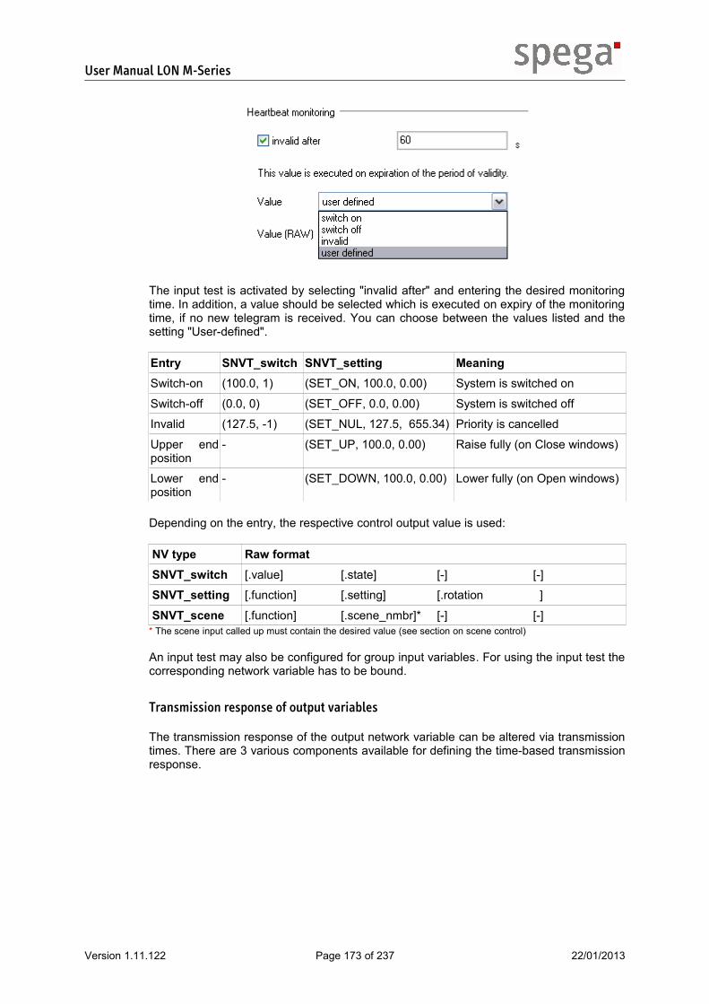
User Manual LON M-Series
The input test is activated by selecting "invalid after" and entering the desired monitoring time. In addition, a value should be selected which is executed on expiry of the monitoring time, if no new telegram is received. You can choose between the values listed and the setting "User-defined".
Entry SNVT_switch SNVT_setting MeaningSwitch-on (100.0, 1) (SET_ON, 100.0, 0.00) System is switched on
Switch-off (0.0, 0) (SET_OFF, 0.0, 0.00) System is switched off
Invalid (127.5, -1) (SET_NUL, 127.5, 655.34) Priority is cancelled
Upper end position
- (SET_UP, 100.0, 0.00) Raise fully (on Close windows)
Lower end position
- (SET_DOWN, 100.0, 0.00) Lower fully (on Open windows)
Depending on the entry, the respective control output value is used:
NV type Raw formatSNVT_switch [.value] [.state] [-] [-]
SNVT_setting [.function] [.setting] [.rotation ]
SNVT_scene [.function] [.scene_nmbr]* [-] [-]* The scene input called up must contain the desired value (see section on scene control)
An input test may also be configured for group input variables. For using the input test the corresponding network variable has to be bound.
Transmission response of output variables
The transmission response of the output network variable can be altered via transmission times. There are 3 various components available for defining the time-based transmission response.
Version 1.11.122 Page 173 of 237 22/01/2013

User Manual LON M-Series
Minimum interval
time
Cyclic transmission
1 3 4 5 6 7 8 9 102
Delay
2
11 12 13 14 15
22
32
33
44
4
6 7 9 10 13 15
4
125
2
55 6
6
measurement /feedback
network output
77 7
99 9
9 1212
1313
1515
DelayValues which are intended to be output may be delayed.
Minimum intervalA minimum time interval may be defined for successive output telegrams, to ensure the receiver has enough time to process the telegrams.
Cyclic transmission (heartbeat)To secure the connection to the receiver the output values may be transmitted cyclically, even without taking the minimum change into account. Note here that cyclic transmission increases the bus load.
The transmission times are set in the object plug-in on the "NVO settings" tab in the "Transmission interval" section.
Cyclic transmission is activated by selecting "Resend every"; the transmission rate can be specified. The minimum interval is activated by selecting "Don't send oftener than every"; the interval can be parameterized. The delay function is activated using input values greater than 0 under "Send delayed with".
Version 1.11.122 Page 174 of 237 22/01/2013

User Manual LON M-Series
4.4.3 Damper actuator
The damper actuator is used to activate various types of drives in HVAC technology and can be adapted as required by parameterizing the object functions. Depending on the application version, the actuator object provides one or two network input variables, which are used to activate the actuator. The use of group objects means that additional input variables are available for central functions. In addition, each object sends back the current position of the actuator on its output network variable.
Overview of object functions
Extended functions are supported in addition to the VDI 3813-compliant room automation functions.
VDI3813 – Functions
• Actuator• Space usage selection• Priority evaluation
Extended function
• Switchable network variable types• Output network variable transmission response• Action in the event of communication faults• Action following resumption of power supply/reset• Activation via groups• Valve rinsing• Pulse width modulation
Parametrization of object functions
The objects are parameterized using the corresponding object plug-ins. These can be started directly on the object from the device plug-in or in the LNS tool.
Action following resumption of power supply or reset
The response following the resumption of a power supply or RESET can be parameterized. A position can be specified here. There is also the possibility of not executing a command. Parametrization is carried out in the object plug-in on the "General" tab.
Depending on the hardware activated, definition of the position of the actuator can be deactivated until the actuator has been moved into one of its end positions. Some actuator modules also feature automatic calibration. More detailed information on this is given in
Version 1.11.122 Page 175 of 237 22/01/2013

User Manual LON M-Series
the relevant module section. If the position cannot be determined correctly, the output network variable will send back an invalid value.
Types of drive
Since some functions depend on the type of drive activated, all drive types supported are listed below:
Type of drive PWM Valve rinsingThermoelectric and motorized actuators
Valve (2-point) x x
Valve (3-point) - x
Fan (on/off, 2-stage, 3-stage) - -
Actuators with continuous control
Valve (constant) - x
Valve (6-way) - x
Actuator
The actuator receives control output values via the input from a higher-level control unit. The current control output value is read out as a feedback message via the output network variable.
General processing of control output valuesThe following control output values can be processed for the actuators.
Control output value
Valve (2-point, 3-point, constant)
Valve (6-way)
Fan (on/off, 2-stage, 3-stage)
0 % Close Close Switch off fan
0 % < x ≤ 100 % Open at x % Open sequence 2 at x % Stage for x% based on threshold values
-100 % ≤ x < 0 % - Open sequence 1 at – x% -
When using fans the control output value is interpreted by means of the actuator's stage threshold values parameterized on the channel.
Feedback valuesWith valves the current position of the valve is output as a feedback signal; with fans the threshold value of the current stage is output. It is possible to define which information is sent back for the feedback signal, particularly in the case of actuators which are activated via the MP bus. You can choose from the following information:
Feedback mode MeaningAbsolute position The feedback contains the current position of the actuator as a
percentage share of the measurable control output value range.
Relative position The feedback contains the current position of the actuator as a percentage share of the control output value range parameterized in the MP actuator.
Absolute volume flow
The feedback contains the current volume flow of the actuator as a percentage share of the maximum measurable volume flow.
Version 1.11.122 Page 176 of 237 22/01/2013

User Manual LON M-Series
Relative volume flow
The feedback contains the current volume flow of the actuator as a percentage share of the maximum volume flow parameterized in the MP actuator.
It can be set in the object plug-in on the "NVO settings" tab in the "Feedback mode (MP bus)" section.
Pulse width modulationIt may be advisable to modify the control output value, depending on the actuator connected and the control principle used. For example, a constant control output value may affect a thermoelectric actuator via pulse width modulation in such a way that the averaged flow rate is proportional to the control output value.
0time
PWM value [%]
value x (without PWM)
tX
100
Tz + tXTz
* 100 % = xtX
Tz
Version 1.11.122 Page 177 of 237 22/01/2013

User Manual LON M-Series
Vtx
0time
PWM value [%]
value x (without PWM)
tX
100
Tz + tXTz
Vx
Vx = Vtx
The pulse width modulation is characterized by the cycle duration Tz. Various cycle times are recommended, depending on the heating system:
Heating/cooling system Cycle timeRadiator heating 15 min.
Underfloor heating 20 – 30 min.
Electric convection heating 15 min.
Chilled ceiling 15-20 min.
Configuration of the pulse width modulation by specifying the cycle time takes place in the object plug-in on the "PWM" tab.
Valve rinsingTo prevent valve stems or flaps from jamming, rinsing takes place automatically after a pre-defined time period, if the actuator was in the initial position throughout this period. The control output is opened fully for the duration of rinsing (upper output limit), then closed again; any parameterized pulse width modulation is ignored here.
The maintenance function can be activated in the object plug-in on the "Maintenance" tab. The rinsing time is also defined here. The duration of a rinse is based on the information given at channel level for the drive concerned.
Version 1.11.122 Page 178 of 237 22/01/2013

User Manual LON M-Series
Priority evaluation
The object is activated via the input network variables. By setting priorities various input variables can be sorted according to their importance. In this way mutual interference caused by activation from more than one source can be avoided. Priority evaluation is parameterized via the object plug-in. If group objects are used as control sources, parts of the priority evaluation must also be set here in the relevant object plug-in.
Principle of operationEach priority has two initial states. Either valid activation values are received, in which case the priority is considered active, or the activity is explicitly retracted, whereby an 'invalid' value is sent.
PRI_1inactiv
PRI_1activ + valid
activation command / value
priority reset
activation command or
value
process value
In the case of a single priority the status diagram shown above applies. As soon as other priorities are added they must be mutually interlocked.
PRI_1inactiv
PRI_1activ + valid
PRI_1activ
Higher PRIO activ?
activation command / value
No
PRI_2inactiv
PRI_2activ + valid
PRI_2activ
Higher PRIO activ?
No
PRI_3inactiv
PRI_3activ + valid
PRI_3activ
Higher PRIO activ?
No
A2
A2
A3
A3
priority reset
activation command or
value
process value
A3priority reset
priority reset
B2
B3
B3
B2 B3 Yes
Yes
Yes
restore
C1
C1*
activation command / value
restore
C2
activation command / value
C1* C2*
As a result each priority is given a further status. It may now be active, however its values may not be executed due to a higher-weighted priority. It loses its validity as soon as a higher priority is activated (Ax events). On the other hand, a priority may regain its validity as soon as the last higher priority is retracted (Bx events) or it replaces higher priorities itself (Cx events). In cases where a priority becomes valid
Version 1.11.122 Page 179 of 237 22/01/2013

User Manual LON M-Series
again because a higher priority has been retracted, it is possible to stipulate for the re-validated priority how it should handle this event.
ParametrizationA full overview of the room and central functions in which the damper actuator is involved is vital for setting the priority evaluation parameters. For this reason the configuration stages are described using an example.
Example A room climate controller for activating a fan is being used in an office. A centralized fan override is provided, whereby only the Maximum speed and Off statuses should be possible.
Step 1 – Selection of input variables1 or 2 input network variables are available on the object, depending on the application. Group objects may also be used for other input variables. The inputs on the object are best suited for local functions and groups are suitable for central functions.
Example In our example we have the control system as a local function and a central function. One input variable on the damper actuator should be used for activation via the room climate controller. A group object is required for central override purposes.
Step 2 – Selection of prioritiesHere you must first consider which priorities are suitable for implementing the functions. In total there are 6 different priorities available with the following weighting:
Automatic < Manual < Override 1 < Weather < Override 2 < Safety
Example In our example the Automatic priority is suitable for activation via the room climate controller. At least one higher priority should be selected for central override. We select 'Manual'.
The priority is set on the respective input network variable used, this also affects activation via groups (see section on groups). The priority can be set in the object plug-in on the tab of the corresponding input variable in the section entitled "Priority".
Step 3 – Defining the type of activationThere are 3 types of activation for each input network variable. This determines how the commands received are processed.
Version 1.11.122 Page 180 of 237 22/01/2013

User Manual LON M-Series
Setting MeaningExecute received command Each telegram on the input variable is set directly as a
new light value.
On switch-on command If a switch-on command is received, the command specified is executed. A switch-off command causes the priority to be retracted.
On switch-off command If a switch-off command is received, the command specified is executed. A switch-on command causes the priority to be retracted.
The "On switch-on command" and "On switch-off command" types of activation use the following switch-on and switch-off commands, depending on the type of network variable used:
NV type Switch-on command Switch-off commandSNVT_switch (100.0,1) (0.0,0)
SNVT_setting (SET_ON,100.0,0.00) (SET_OFF,0.0,0.00)
On activating the priority, a series of different commands can be selected for the "On switch-on command" and "On switch-off command" types of activation, whereby those commands not listed are not relevant for the damper actuator.
Command MeaningNo command The priority is activated, however no command is executed
Off/close Close valves, switch off fan
On/open Open valves fully, switch fan to highest level
Example In our example we are using the "Execute received command" type of activation for the room climate controller. This allows us to stipulate that the object is activated with direct control commands. We will use the "On switch-on command" type of activation for the central override. "On/open" is input as the command.
The type of activation is defined separately for each input network variable; this also relates to groups (see section on groups). It is set in the object plug-in on the tab of the corresponding input variable in the section entitled "Priority".
Step 4 – How is the activity of the priorities reset?
Priorities are usually reset via direct telegrams; here the corresponding invalid value should be sent, depending on the type of NV set. With the "On switch-on command"
Version 1.11.122 Page 181 of 237 22/01/2013

User Manual LON M-Series
type of activation, switching-off causes the priority to be reset. The same applies when switching on using the "On switch-off command" type of activation. The invalid values for various types of NV are shown in the table:
NV type Invalid valueSNVT_switch (x, -1) any values are possible for x
SNVT_setting (SET_NUL, x, y) any values are possible for x and y
SNVT_scene The scene input called up must contain an invalid value (see section on scene control)
SNVT_lev_percent (163.835)
Example In this example no cancellation is required for room climate control, as this is already the lowest priority value. Switching off causes the central override to be cancelled directly.
If an activation source is not able to trigger a cancellation directly from an invalid value (e.g. manual operation), there are 2 mechanisms available for switching the priority off again. Both alternatives are also available when using groups.
Alternative 1 – Automatic priority cancellation
First of all, a period of validity can be specified on the corresponding input network variable. If the specified time elapses without new, valid control output values being received, this event is treated as though an invalid value for cancellation had been received. This invalid value must therefore be explicitly specified below the relevant input network variable. For using the automatic priority cancellation the corresponding network variable has to be bound.
Example In our example automatic priority cancellation is not required.
Automatic priority cancellation is set in the object plug-in on the "NVI settings" tab in the section entitled "Heartbeat monitoring". It should be noted that this function cannot be used at the same time as the treatment of communications faults on the same input variable.
Automatic priority cancellation is activated by selecting "invalid after" and entering the desired period of validity. "Invalid" should be selected as a value in order to ensure cancellation of the priority on expiry of the period of validity.
Alternative 2 – Priority restore
The second mechanism allows an active though invalid priority to try to restore its validity by deactivating higher priorities by means of a special command.
Version 1.11.122 Page 182 of 237 22/01/2013

User Manual LON M-Series
Example In our example no priority restoration is required.
The restore mechanism applies across all objects for all network inputs with the same priority (even if on a group) and is configured in the object plug-in on the "Priority settings" tab in the section entitled "Restore behaviour".
For each of the possible priorities you must first enter which of the higher priorities it can reset. If at least one priority is selected, the command must also be given as to which priority should initiate the reset. If this command is then received on the desired low priority, active priorities which are marked as resettable are reset. A priority reset can only be successfully implemented if no higher priorities are active after it. It should be noted that the return behaviour described below does not apply after a priority restoration.
Step 5 – Defining the return behaviourThe reutrn behaviour describes what happens for each priority when it is reactivated because one/all higher priorities has/have been cancelled. You can choose between 3 different reactions for this object-wide setting:
Reaction DescriptionNone The system waits until a new operating command is received which is
then set normally.
Last abs. command
The last operating command received (absolute) is executed. Operating commands which were received when the priority was still active but invalid are also taken into account here.
Command A specific command is executed
It should be noted that the response following a reset (see previous section) cannot be specified, it always corresponds to the reaction "none". To execute a specific command it is possible to choose between the commands listed, depending on the type of NV, whereby those commands not listed are not relevant for the damper actuator.
Command SNVT_switch SNVT_setting SNVT_lev_percentNo command (127.5, -1) (SET_NUL, 127.5, 655.34) (163.835)
Off/close (0.0, 0) (SET_OFF, 0.0, 0.00) (0.000)
On/open (100.0, 1) (SET_ON, 100.0, 0.00) (100.000)
Version 1.11.122 Page 183 of 237 22/01/2013

User Manual LON M-Series
If the NV type SNVT_scene is present, the scene entry called up must contain the corresponding value. The desired response can be specified in the object plug-in on the "Priority settings" in the section entitled "Return behaviour".
The reaction is set for each priority under "Execute" when the priority is restored. If required the command to be executed must also be selected.
Example In the example the last absolute command is executed on return to 'Automatic'.
Step 6 – Response following power resumption and RESETIf required, the activity of individual priorities can also be maintained beyond a RESET. In such cases this also influences the response following a RESET. For each priority a non-volatile memory has been set, it will be evaluated after a RESET or power resumption, if the priority was active before it. In this case the priority will be reactivated. Is one of the these priorities the valid priority after the evaluation, a configured positioning calibration (channel configuration) or a configured treatment on RESET (object configuration) will not be executed for remaining the position. If there is no active priority present, the parameterized treatment is executed following power resumption / reset.
Example In our example none of the priorities used need to be stored in a non-volatile memory.
If priorities are to be retained beyond a reset, this can be configured on the "Save priority" tab.
Version 1.11.122 Page 184 of 237 22/01/2013

User Manual LON M-Series
Use of groups
Group objects for controlling the damper actuators can be used. These are located on the same device and provide a network variable as an interface to all its group members. The ability to operate all output objects via a group object too means that central commands can be set up in such a way that only one network variable has to be bound for each device. Therefore, no alias table entries are used on the transmitting device, which would be required for binding the actuator objects separately.
The assignment of actuator objects to group objects has to be done in the device plug-in, as described in the relevant section. Operation of the group controllers and their parametrization are described in the section on the group objects.
Switchable network variables
Various types of network variable can be used for the damper actuator. In this way, the object can be adapted to the network interfaces available in the network.. For some functions the respective type of NV is relevant when setting the parameters, for example in the case of priority evaluation. The standard types listed may be used:
NV types allowed for input variables allowed for output variablesSNVT_setting x -
SNVT_switch x* -
SNVT_scene x -
SNVT_lev_percent x x
The NV type is set in the object plug-in - for input variables this is done on the "NVI settings" tab in the section entitled "Input network variable", and for output variables on the "NVO settings" tab in the section "Output network variables".
Version 1.11.122 Page 185 of 237 22/01/2013

User Manual LON M-Series
Space usage selection (scene control)
A scene controller is available for the damper actuator, allowing it to be activated via scenes. For this the network variable provided for activation purposes should set to 'SNVT_scene'. Telegrams on the input variable are processed as follows:
SNVT_scene MeaningSC_LEARN, x Save output variable as a control value for scene x
SC_RECALL, x Call up scene x
The scene plug-in for parameterizing the scene controller is run directly on the damper actuator.
The scene controller contains a fixed number of entries, whereby the scene number of the first entry may be parameterized. All other entries have ascending numbers, as can be seen in column "No." Each entry to be used must first be activated in the column "Active". The scene entries are of type 'SNVT_switch' for the damper actuator.
Version 1.11.122 Page 186 of 237 22/01/2013

User Manual LON M-Series
Action in the event of communication faults
Faulty input telegrams (see LonMark specifications) are ignored. In order to deal with communication faults and a related possible failure of individual activation sources, an input test can be set for each input network variable. For this the activation source must support cyclic transmission and its parameters be set accordingly. If no new network telegram is received within a parameterized time period, a previously defined command is executed. This may be used for activating or deactivating the relevant priority or may contain a specific control output value.
It should be noted that this function cannot be used at the same time as automatic priority cancellation on the same input variable. Parametrization of the input test is performed for the input variable concerned in the object plug-in on the "NVI settings" tab in the section entitled "Heartbeat monitoring".
The input test is activated by selecting "invalid after" and entering the desired monitoring time. In addition, a value should be selected which is executed on expiry of the monitoring time, if no new telegram is received. You can choose between the values listed and the setting "User-defined".
Entry MeaningSwitch-on System is switched on
Switch-off System is switched off
Invalid Priority is cancelled
Open valve (100%) 6-way valve S2
Open valve fully / open sequence 2 fully (6-way valve only)
Close valve Close valve fully
6-way valve S1 (-100%)
Open sequence 1 fully (6-way valve only)
Depending on the entry, the respective control output value is used:
Entry SNVT_switch SNVT_setting SNVT_lev_percentSwitch-on (100.0, 1) (SET_ON, 100.0, 0.00) -
Switch-off (0.0, 0) (SET_OFF, 0.0, 0.00) -
Invalid (127.5, -1) (SET_NUL, 127.5, 655.34) (163.835)
Open valve (100%) 6-way valve S2
- - (100.000)
Close valve - - (0.000)
Version 1.11.122 Page 187 of 237 22/01/2013

User Manual LON M-Series
Entry SNVT_switch SNVT_setting SNVT_lev_percent6-way valve S1 (-100%)
- - (-100.000)
When selecting "User-defined" the desired value must be given in raw data form according to the type of NV used.
NV type Raw formatSNVT_switch [.value] [.state] [-] [-]
SNVT_setting [.function] [.setting] [.rotation ]
SNVT_scene [.function] [.scene_nmbr]* [-] [-]
SNVT_lev_percent [value] [value] [-] [-]* The scene input called up must contain the desired value (see section on scene control)
An input test may also be configured for group input variables. For using the input test the corresponding network variable has to be bound.
Transmission response of output variables
The transmission response of the output variable is determined on the basis of the minimum change request with regard to the values to be transmitted and definable transmission times.
UniversalActuator
nvoUAValue
Minimum change Transmission timing
V_STAV_STA V_STAV_STA
Minimum changeIt is possible to define the resolution of the output value range by setting minimum changes. In the case of objects with frequent value changes by small amounts, the bus load can be reduced in this way.
The desired minimum change of values before retransmission can be specified as absolute or relative. Absolute minimum changes require changes by a fixed amount; with relative minimum changes the required change amount increases as the values increase.
minimum change
negative positive value
absolute
relative
Version 1.11.122 Page 188 of 237 22/01/2013

User Manual LON M-Series
With a combination of both variants it is possible to combine constant changes with low values with increasing change requests with high values.
The minimum changes can be set in the object plug-in on the "Transmission response" tab in the section entitled "Value change for retransmission".
Time-based transmission responseThere are 3 various components available for defining the time-based transmission response.
Minimum interval
time
Cyclic transmission
1 3 4 5 6 7 8 9 102
Delay
2
11 12 13 14 15
22
32
33
44
4
6 7 9 10 13 15
4
125
2
55 6
6
measurement /feedback
network output
77 7
99 9
9 1212
1313
1515
DelayValues which are intended to be output may be delayed.
Minimum intervalA minimum time interval may be defined for successive output telegrams, to ensure the receiver has enough time to process the telegrams.
Cyclic transmission (heartbeat)To secure the connection to the receiver the output values may be transmitted cyclically, even without taking the minimum change into account. Note here that cyclic transmission increases the bus load.
Parametrization of transmission timesThe transmission times are set in the object plug-in on the "NVO settings" tab in the "Transmission interval" section.
Cyclic transmission is activated by selecting "Resend after"; the transmission rate can be specified. The minimum interval is activated by selecting "Send no more than
Version 1.11.122 Page 189 of 237 22/01/2013

User Manual LON M-Series
every"; the interval can be parameterized. The delay function is activated using input values greater than 0 under "Delay sending by".
Version 1.11.122 Page 190 of 237 22/01/2013

User Manual LON M-Series
4.4.4 Analog input
The analog input is used for converting physical variables into LON network telegrams with scalar content. For example, an active 0-10V temperature sensor can be converted into a network telegram of type SNVT_temp_p. The object behaviour can be adjusted by adapting the parameter settings of the object functions to the relevant requirements. The sensor object sends back the sensor's current measured value on its output network variable.
Overview of object functions
Extended functions are supported in addition to the VDI 3813-compliant room automation functions.
VDI3813 – Functions
• Air temperature measurement• Brightness measurement• Air quality measurement
Extended function
• Switchable network variable types• Output network variable transmission response
Parametrization of object functions
The objects are parameterized using the corresponding object plug-ins. These can be started directly from the device plug-in or on the object itself.
Switchable network variables
The status of the connected sensor can be read out in one of the formats listed, depending on requirements. In this way, the object can be adapted in line with the meaning of the measured value and the network interfaces.
NV types allowed for nvo NV types allowed for nvoSNVT_amp x SNVT_press_p x
SNVT_amp_mil x SNVT_rpm x
SNVT_angle_deg x SNVT_setting x
SNVT_flow x SNVT_speed x
SNVT_flow_mil x SNVT_speed_mil x
SNVT_flow_p x SNVT_switch x
SNVT_lev_cont x SNVT_temp x
SNVT_lev_percent x SNVT_temp_p x
SNVT_lux x SNVT_vol x
SNVT_power x SNVT_vol_kilo x
Version 1.11.122 Page 191 of 237 22/01/2013

User Manual LON M-Series
NV types allowed for nvo NV types allowed for nvoSNVT_power_kilo x SNVT_volt x
SNVT_ppm x SNVT_volt_kilo x
SNVT_press x SNVT_volt_mil x
The type of NV is set in the object plug-in on the "General" tab in the "Output network variable" section.
Sensor acquisition
The functions listed below may be used depending on the assigned sensor:
Sensor type Air temperature measurement
Brightness measurement
Air quality measurement
Temperature sensor x - -
Brightness sensor, lux meter
- x -
CO2 sensor, mixed gas sensor
- - x
Other Standard functionality of analog input
Standard functionalityThe analog input can measure values within a measuring range specified by the hardware settings and convert them linearly into a parameterizable range of output values. Parametrization is carried out in the object plug-in on the "General" tab in the "Scaling" section. The upper and lower limit of the output value range should be indicated on the graphic display. The values which can be input are formatted according to the type of NV set and limited to the range of values of the NV type.
Air temperature measurementWith an air temperature measurement the temperature of a specific area is measured by a temperature sensor. Parameters are set for appropriate scaling of the output range to the range of measurement values. The smallest possible resolution is achieved based on the sensor resolution and output value formatting selected.
Version 1.11.122 Page 192 of 237 22/01/2013

User Manual LON M-Series
Brightness measurementBrightness measurements are provided by a lux meter. Parameters are set for appropriate scaling of the output range to the range of measurement values. The smallest possible resolution is achieved based on the sensor resolution and output value formatting selected.
Air quality measurementAir quality measurements are usually provided by CO2 or mixed gas sensors. Parameters are set for appropriate scaling of the output range to the range of measurement values. The smallest possible resolution is achieved based on the sensor resolution and output value formatting selected.
Version 1.11.122 Page 193 of 237 22/01/2013

User Manual LON M-Series
Transmission response of output variables
The transmission response of the output variable is determined on the basis of the minimum change request with regard to the values to be transmitted and definable transmission times.
UniversalActuator
nvoUAValue
Minimum change Transmission timing
V_STAV_STA V_STAV_STA
Minimum changeIt is possible to define the resolution of the output value range by setting minimum changes. In the case of objects with frequent value changes by small amounts, the bus load can be reduced in this way.
The desired minimum change of values before retransmission can be specified as absolute or relative. Absolute minimum changes require changes by a fixed amount; with relative minimum changes the required change amount increases as the values increase.
Version 1.11.122 Page 194 of 237 22/01/2013

User Manual LON M-Series
minimum change
negative positive value
absolute
relative
With a combination of both variants it is possible to combine constant changes with low values with increasing change requests with high values.
The minimum changes can be set in the object plug-in on the "Transmission response" tab in the section entitled "Value change for retransmission".
Time-based transmission responseThere are 3 various components available for defining the time-based transmission response.
Minimum interval
time
Cyclic transmission
1 3 4 5 6 7 8 9 102
Delay
2
11 12 13 14 15
22
32
33
44
4
6 7 9 10 13 15
4
125
2
55 6
6
measurement /feedback
network output
77 7
99 9
9 1212
1313
1515
DelayValues which are intended to be output may be delayed.
Minimum intervalA minimum time interval may be defined for successive output telegrams, to ensure the receiver has enough time to process the telegrams.
Cyclic transmission (heartbeat)To secure the connection to the receiver the output values may be transmitted cyclically, even without taking the minimum change into account. Note here that cyclic transmission increases the bus load.
Version 1.11.122 Page 195 of 237 22/01/2013

User Manual LON M-Series
Parametrization of transmission timesThe transmission times are set in the object plug-in on the "Transmission response" tab in the "Transmission interval" section.
Cyclic transmission is activated by selecting "Resend after"; the transmission rate can be specified. The minimum interval is activated by selecting "Send no more than every"; the interval can be parameterized. The delay function is activated using input values greater than 0 under "Delay sending by".
Version 1.11.122 Page 196 of 237 22/01/2013

User Manual LON M-Series
4.4.5 Binary input
The binary input enables random binary contacts to be detected and their status to be delivered to the network and can be adapted to the relevant requirements by parameterizing the object functions. The sensor object sends back the sensor's current status value on its output network variable.
Overview of object functions
Extended functions are supported in addition to the VDI 3813-compliant room automation functions.
VDI3813 – Functions
• Occupancy detection• Window monitoring• Dew point monitoring• Occupancy setting
Extended function
• Switchable network variable types• Output network variable transmission response
Parametrization of object functions
The objects are parameterized using the corresponding object plug-ins. These can be started directly from the device plug-in or on the object itself.
Switchable network variables
The status of the connected sensor can be read out in one of the formats listed, depending on requirements. In this way, the object can be adapted to the network interfaces available in the network.
NV types allowed for output variablesSNVT_setting x
SNVT_switch x
SNVT_occupancy x
The type of NV is set in the object plug-in on the "General" tab in the "Output network variable" section.
Version 1.11.122 Page 197 of 237 22/01/2013

User Manual LON M-Series
Sensor acquisition
The functions listed below may be used depending on the assigned sensor:
Sensor type Occupancy detection
Occupancy setting
Window monitoring
Dew point monitoring
Motion sensors, occupancy sensors
x - - -
Occupancy switches, key-operated switches, key cards
- x - -
Window contacts - - x -
Dew point sensors - - - x
Other Standard functionality of binary input
Standard functionalityThe binary input can differentiate between switching on and off. A telegram, which is sent when the contact status changes, is assigned to both events. A minimum hold time can be defined for switching on; the telegram for switch-off is not sent until this time has elapsed.
Parametrization is carried out in the object plug-in on the "General" tab. Depending on the output variable formatting used, you can select in the "Contact function" section whether a break contact, make contact or occupancy sensor is present.
In such cases the standard switch-on and switch-off telegrams used are input. If none of the pre-configured functions are suitable, the parameter settings for the switch-on and switch-off telegrams can be freely configured under "User-defined". To simplify the process, you can also choose between standardized and user-defined settings for the individual telegrams. The following entries are available as standard telegrams:
Telegram SNVT_switch SNVT_setting SNVT_occupancySwitch off (0.0, 0) (SET_OFF, 0.0, 0.00)
Switch on (100.0, 1)) (SET_ON, 100.0, 0.00) -
Invalid (0.0, -1) (SET_NUL, 0.0, 0.00) (OC_NUL)
Occupied - - (OC_OCCUPIED)
Unoccupied - - (OC_UNOCCUPIED)
Version 1.11.122 Page 198 of 237 22/01/2013

User Manual LON M-Series
Telegram SNVT_switch SNVT_setting SNVT_occupancyBypass - - (OC_BYPASS)
Standby - - (OC_STANDBY)
When selecting "User-defined" the desired telegram must be given in raw data form according to the type of NV used.
NV type Raw formatSNVT_switch [.value] [.state] [-] [-]
SNVT_setting [.function] [.setting] [.rotation ]
SNVT_occupancy [occupancy] [-] [-] [-]
In the "Hold time" section on the "General" tab you can specify a minimum hold time for which a switch-on telegram is valid before a switch-off telegram may be sent.
Occupancy detectionWith occupancy detection the occupancy status of an area is established using motion or occupancy sensors. These sensors react when an area is occupied, usually caused by a continual, short-term change in their status. For this reason, a hold time for the occupancy status following detection may be set to prevent the system continually switching back and forth.
Version 1.11.122 Page 199 of 237 22/01/2013

User Manual LON M-Series
Occupancy settingAs a rule, the occupancy function is used if the occupancy status of an area is activated manually. The operating procedure can be defined by parameterizing switch-on and switch-off telegrams.
Window monitoring
Version 1.11.122 Page 200 of 237 22/01/2013

User Manual LON M-Series
The status of windows can also be monitored using the binary object. The parameters of the switch-on and switch-off telegrams of an object can be freely configured depending on the type of sensor used.
Dew point monitoringThe binary input is suitable for acquiring conventional dew point sensors; the parameters of the switch-on and switch-off telegrams can be freely configured.
Version 1.11.122 Page 201 of 237 22/01/2013

User Manual LON M-Series
Transmission response of output variables
The transmission response of the output network variable can be altered via transmission times. There are 3 various components available for defining the time-based transmission response.
Minimum interval
time
Cyclic transmission
1 3 4 5 6 7 8 9 102
Delay
2
11 12 13 14 15
22
32
33
44
4
6 7 9 10 13 15
4
125
2
55 6
6
measurement /feedback
network output
77 7
99 9
9 1212
1313
1515
DelayValues which are intended to be output may be delayed.
Minimum intervalA minimum time interval may be defined for successive output telegrams, to ensure the receiver has enough time to process the telegrams.
Cyclic transmission (heartbeat)To secure the connection to the receiver the output values may be transmitted cyclically, even without taking the minimum change into account. Note here that cyclic transmission increases the bus load.
The transmission times are set in the object plug-in on the "Transmission response" tab in the "Transmission interval" section.
Cyclic transmission is activated by selecting "Resend after"; the transmission rate can be specified. The minimum interval is activated by selecting "Send no more than every"; the interval can be parameterized. The delay function is activated using input values greater than 0 under "Delay sending by".
Version 1.11.122 Page 202 of 237 22/01/2013

User Manual LON M-Series
4.5. Configuration of groupsThe applications provide universal usable groups. The object type to be controlled has to be set in the device plug-in, as described in the relevant section. The group parametrization varies with the object type to be controlled.
4.5.1 Overview of functions
Group objects are suitable for central functions where several actuator objects need to be activated. Extended functions are supported in addition to the VDI 3813-compliant room automation functions:
VDI3813 – Functions
• Link to priority evaluation of the objects• Space usage selection within the objects
Extended function
• Switchable network variable types• Action in the event of communication faults• Delayed routing of telegrams
4.5.2 Parametrization of functions
The groups are parameterized via the group plug-in. This can be started directly from the device plug-in or on the group object itself.
General processing of network telegrams
Routing to the members of the group takes place internally but behaves as though the input variable was on each member object directly. The part of the parametrization which has to be conducted separately for each network variable in the objects, too, is set directly in the group plug-in for the group input. All other settings for the object behaviour of the members are specified by their object parametrization. It is therefore possible to realize central functions via the groups which require different reactions from the individual members of the group.
Delayed processing of telegrams
The groups are primarily used for realizing central automation functions. Here, many actuator objects are often activated via several groups at once, which can lead to voltage peaks. To alleviate this situation the groups feature the option of delayed telegram processing. You can choose between two strategies in terms of the temporal distribution of the activation process. On the one hand, an absolute delay can be stored for each group, while on the other hand a time period can be specified within which the telegram must be processed at the latest; the group then randomly determines the respective telegram delay within the set time period.
Version 1.11.122 Page 203 of 237 22/01/2013

User Manual LON M-Series
Delayed telegram processing can be set in the group plug-in on the "General" tab.
Priority evaluation
The core function of priority evaluation is set via the object plug-ins of the group members. If group objects are used as activation sources, parts of the priority evaluation must also be set here in the relevant group plug-in.
Principle of operation
The basic functionality of priority evaluation is detailed in the description of the objects.
Parametrization
A full overview of the room and central functions in which the group members are involved is vital for setting the priority evaluation parameters. As described in the object, priority evaluation configuration takes place in several steps.
Step 1 – Selection of input variablesThe group provides an input network variable suitable for central functions.
Step 2 – Selection of prioritiesHere you must first consider which priorities are suitable for implementing the functions. In total there are 6 different priorities available with the following weighting:
Automatic < Manual < Override 1 < Weather < Override 2 < Safety
Version 1.11.122 Page 204 of 237 22/01/2013

User Manual LON M-Series
The priority is set on the respective input network variable. The priority can be set in the group plug-in on the "NVI settings" tab in section entitled "Priority".
Step 3 – Defining the type of activationThere are 3 types of activation for each input network variable. This determines how the commands received are processed.
Setting MeaningExecute received command Each telegram on the input variable is set directly as a
new light value.
On switch-on command If a switch-on command is received, the command specified is executed. A switch-off command causes the priority to be retracted.
On switch-off command If a switch-off command is received, the command specified is executed. A switch-on command causes the priority to be retracted.
The "On switch-on command" and "On switch-off command" types of activation use the following switch-on and switch-off commands, depending on the type of network variable used:
NV type Switch-on command Switch-off commandSNVT_switch (100.0,1) (0.0,0)
SNVT_setting (SET_ON,100.0,0.00) (SET_OFF,0.0,0.00)
On activating the priority, a series of different commands can be selected for the "On switch-on command" and "On switch-off command" types of activation; the meaning of these commands depends on the type of object activated and can be found in the relevant section for the object type. The type of activation is configured in the group plug-in on the "NVI settings" tab in the section entitled "Priority".
Version 1.11.122 Page 205 of 237 22/01/2013

User Manual LON M-Series
Step 4 – How is the activity of the priorities reset?Priorities are usually reset via direct telegrams; here the corresponding invalid value should be sent, depending on the type of NV set. With the "On switch-on command" type of activation, switching-off causes the priority to be reset. The same applies when switching on using the "On switch-off command" type of activation. The invalid values for various types of NV are shown in the table:
NV type Invalid valueSNVT_switch (x, -1) any values are possible for x
SNVT_setting (SET_NUL, x, y) any values are possible for x and y
SNVT_scene The scene input called up must contain an invalid value (see section on scene control)
SNVT_lev_percent (163.835)
If an activation source is not able to trigger a cancellation directly from an invalid value (e.g. manual operation), there are 2 mechanisms available for switching the priority off again. Both alternatives are also available when using groups.
Alternative 1 – Automatic priority cancellation
First of all, a period of validity can be specified on the corresponding input network variable. If the specified time elapses without new, valid control output values being received, this event is treated as though an invalid value for cancellation had been received. This invalid value must therefore be explicitly specified below the relevant input network variable. For using the automatic priority cancellation the corresponding network variable has to be bound.
Automatic priority cancellation is set in the object plug-in on the "NVI settings" tab in the section entitled "Heartbeat monitoring". It should be noted that this function cannot be used at the same time as the treatment of communications faults on the same input variable.
Automatic priority cancellation is activated by selecting "invalid after" and entering the desired period of validity. "Invalid" should be selected as a value in order to ensure cancellation of the priority on expiry of the period of validity.
Alternative 2 – Priority restore
The second mechanism allows an active though invalid priority to try to restore its validity by deactivating higher priorities by means of a special command.
Version 1.11.122 Page 206 of 237 22/01/2013

User Manual LON M-Series
The restore mechanism applies for each object to all network inputs with the same priority (even if on a group) and is configured for each individual group member in the object plug-in on the "Priority settings" tab in the section entitled "Restore behaviour". Details can be found in the section of the manual which deals with the relevant object type.
Step 5 – Defining the reset responseThe reset response describes what happens for each priority when it is reactivated because one/all higher priorities has/have been cancelled. This is set for each group member in the object plug-in on the "Priority settings" tab in the "Reset response" section. Details can be found in the section of the manual which deals with the relevant object type.
Step 6 – Response following power resumption and RESETIf required, the activity of individual priorities can also be maintained beyond a RESET. In such cases this also influences the response following a RESET. The type of response is set for each group object the object plug-in on the "Priority" tab in the "Save priority" section. Details can be found in the section of the manual which deals with the relevant object type.
Switchable network variables
Various types of network variable can be used for the group. In this way, the object can be adapted to the network interfaces available in the network. For some functions the respective type of NV is relevant when setting the parameters, for example in the case of priority evaluation. The standard types permissible depend on the object type activated:
NV types Lighting actuator Sunblind actuator Damper actuatorSNVT_setting x x x
SNVT_switch x x x
SNVT_scene x x x
SNVT_lev_percent - - x
The type of NV is set in the group plug-in on the "NVI settings" tab in the "Input network variable" section.
Space usage selection within the objects
If the input network variable of the group object is set to 'SNVT_scene', the scene controller present in the member objects can be used for space usage control. Once telegrams on the input variable have been forwarded to the objects, they are processed by them as follows:
SNVT_scene MeaningSC_LEARN, x Save output variable as a control value for scene x
SC_RECALL, x Call up scene x
Version 1.11.122 Page 207 of 237 22/01/2013

User Manual LON M-Series
The scene controller is parameterized via its own plug-in which can be run on the relevant member object. Parametrization of the scene controller is described in further detail in the section pertaining to the object type in question.
Action in the event of communication faults
Faulty input telegrams (see LonMark specifications) are ignored. In order to deal with communication faults and a related possible failure of individual activation sources, an input test can be set for each input network variable. For this the activation source must support cyclic transmission and its parameters be set accordingly. If no new network telegram is received within a parameterized time period, a previously defined command is executed. This may be used for activating or deactivating the relevant priority or may contain a specific control output value or movement command.
It should be noted that this function cannot be used at the same time as automatic priority cancellation on the same input variable. Parametrization of the input test is performed for the input variable concerned in the group object plug-in on the "NVI settings" tab in the section entitled "Heartbeat monitoring".
The input test is activated by selecting "invalid after" and entering the desired monitoring time. In addition, a value should be selected which is executed on expiry of the monitoring time, if no new telegram is received. You can choose between the values listed and the setting "User-defined". The selection and meaning of the values that may be chosen is determined by the object type to be activated.
Entry Meaning
Lam
p ac
tuat
or
Sunb
lind
actu
ator
HVA
C a
ctua
tor
Switch-on System is switched on x x x
Switch-off System is switched off x x x
Invalid Priority is cancelled x x x
Upper end position Raise fully (on Close windows) - x -
Lower end position Lower fully (on Open windows) - x -
Open valve (100%) 6-way valve S2
Open valve fully / open sequence 2 fully (6-way valve only)
- - x
Version 1.11.122 Page 208 of 237 22/01/2013

User Manual LON M-Series
Entry Meaning
Lam
p ac
tuat
or
Sunb
lind
actu
ator
HVA
C a
ctua
tor
Close valve Close valve fully - - x
6-way valve S1 (-100%)
Open sequence 1 fully (6-way valve only) - - x
The following values are used here depending on the NV type of the input variable.
Entry SNVT_switch SNVT_setting SNVT_lev_percentSwitch-on (100.0, 1) (SET_ON, 100.0, 0.00) -
Switch-off (0.0, 0) (SET_OFF, 0.0, 0.00) -
Invalid (127.5, -1) (SET_NUL, 127.5, 655.34) (163.835)
Upper end position - (SET_UP, 100.0, 0.00) -
Lower end position - (SET_DOWN, 100.0, 0.00) -
Open valve (100%) 6-way valve S2
- - (100.000)
Close valve - - (0.000)
6-way valve S1 (-100%)
- - (-100.000)
When selecting "User-defined" the desired value must be given in raw data form according to the type of NV used.
NV type Raw formatSNVT_switch [.value] [.state] [-] [-]
SNVT_setting [.function] [.setting] [.rotation ]
SNVT_scene [.function] [.scene_nmbr]* [-] [-]
SNVT_lev_percent [value] [value] [-] [-]* The scene input called up must contain the desired value (see section on scene control)
Version 1.11.122 Page 209 of 237 22/01/2013

User Manual LON M-Series
4.6. ManagementThe object management on the device allows status requests and reports device and object failures.
4.6.1 Overview of functions
The administrative functions are used by network management systems and the plug-ins for communication with the device and for status acquisition purposes. A building control unit or other central control units can use the following functions:
Function Intended applicationDevice management Acquisition and alteration of object statuses
Status feedback based on LonMark
Provides information on objects and assigned channels via the standard interface
Extended status feedback Summarized status information for easier acquisition via building control systems
Device localization Optional display of device ID
4.6.2 Functional description
Device management
Various requests and commands can be sent to the device and its function objects via the network variable nviRequest of the NodeObject.
Command Type of command
Meaning
RQ_NORMAL Status change Resets function objects with an 'override' or 'disabled' status
RQ_UPDATE_ STATUS
Status request Determines the status of the device or a function object, output on nvoStatus
RQ_REPORT_ MASK
Status mask Provides all statuses which can be adopted by the device or function object, output on nvoStatus
RQ_ENABLE Status change Resets function objects with a 'disabled' status
RQ_DISABLED Status change Sets function objects to the 'disabled' status
Status feedback based on LonMark
The status of the device and individual objects can be requested via the network variable nviRequest of the NodeObject. The following commands should be used:
nviRequest Meaning{RQ_REPORT_MASK, 0} Determines the status mask of the device
Version 1.11.122 Page 210 of 237 22/01/2013

User Manual LON M-Series
nviRequest Meaning{RQ_REPORT_MASK, n} Determines the status mask of the function object ('n') on
the device (first object after the NodeObject is given the number 1)
{RQ_UPDATE_STATUS, 0} Determines the status of the device
{RQ_UPDATE_STATUS, n} Determines the status of the function object ('n') on the device (first object after the NodeObject is given the number 1)
The response to the request can be found in the network variable nvoStatus of the NodeObject.
Status mask
The status mask displays which status messages are supported by the respective object. All status elements which can be adopted by the corresponding function object or device are used. Since the response has to do with a status mask, it can be seen that the element nvoStatus.report_mask has been set.
Statuses
The following table gives the meaning of the elements in the response to the nvoStatus. You can determine from the status mask which elements an object is able to report. The reporting of hardware-related statuses depends on whether this is supported by the assigned channels and on the relevant modules.
NvoStatus. elements Meaninginvalid_id This element is used if the .object_id used for the request
is invalid.
invalid_request This element is used if the object does not support the command sent in .object_request.
disabled This element shows that the object has a 'disabled' status.
open_circuit This element shows whether there is a hardware fault or connection error on a module with a least one channel assigned to the object.
mechanical_fault This element shows whether a fault has occurred in the I/Os of a field device assigned to the object.
feedback_failure This element shows whether there is a communications problem with at least one of the assigned channels.
electrical_fault This element is used if a hardware error has been identified on at least one of the assigned channels/field devices.
unable_to_measure If a fault has occurred during the initialization of a module or an assigned channel/field device, this element is used to show it.
comm_failure This element indicates communications faults in the LON network which have occurred on the object requested.
self_test_in_progress This element indicates active initialization processes, synchronizations and clearance tests.
Version 1.11.122 Page 211 of 237 22/01/2013

User Manual LON M-Series
NvoStatus. elements Meaninglocked_out This element indicates non-parameterized devices or
devices which have not been parameterized via plug-in or overridden by the plug-in.
manual_control If one of the assigned channels is overridden, this is shown here.
in_alarm The operating limits on one of the assigned channels/field devices have been exceeded.
report_mask This element is used for a status mask.
alarm_notify_disabled This element indicates that there are communication problems with a module with assigned channels, meaning that further status messages for the channels are not possible.
Extended status feedback
For easier acquisition of important object statuses during operation, the NodeObject offers nvoDeviceStatus. For using the extended status messages it is necessary to set the configuration property UCPTdeviceStateUse below nvoDeviceState to the value {DSU_OBJ_STATES} (2).
1 0
nvoDeviceState {1 0 0 0 0 0 1 0 0 0 0 0 0 0 … 0 0}
Nod
eObj
ect
Uni
vers
alO
bjec
t[2]
Uni
vers
alO
bjec
t[1]
Uni
vers
alO
bjec
t[0]
1 0summarized state of all UniversalObjects
peripherie failure on the subbus device
subbus device communication error / subbus device failure
The statuses are shown per object to mirror the logical assignment of the field devices. 2 bits are used per object for output. The picture shows the usage of the first four objects of the device. The bits for the node object have a special position.The first bit shows if any bit for the universal objects is set. Therefore this bit can be used for evaluating the overall status. The second bit for the node object is not used and reserved for future use.
For universal objects the first bit indicates an periphery error in at least one assigned field device. The second bit indicates an hardware error or an communication problem of at least one of the assigned field devices.
Note here that testing for errors at the connected modules are executed every 2 minutes. The maximum response time for indicating an error is:
TResponseMax = (2 min * number of connected and configured modules)
Version 1.11.122 Page 212 of 237 22/01/2013

User Manual LON M-Series
Device localization
Text of 1 to 31 characters long can be stored in the NodeObject; this is used to identify the device position.
Version 1.11.122 Page 213 of 237 22/01/2013

User Manual LON M-Series
5. Appendix
5.1. SupportThe information given in this manual was carefully compiled. Should you have any further questions regarding this product, please contact:
spega - Spelsberg Gebäudeautomation GmbHZechenstr. 70D-47443 MoersGermanyTel. +49 (2841) 88049-0Fax: +49 (2841) 88049-49Email: [email protected]
5.2. Warranty and liabilityThe warranty for the device - unless otherwise contractually agreed - shall be 12 months from delivery. spega cannot assume any warranty for damage to the product resulting from failure to observe the information and instructions given in this manual, or if the device is used for anything other than its intended purpose or in ambient conditions other than those specified. In such cases liability for consequential damage to persons or property is also excluded.
5.3. spega e.control plug-insTo ensure our components can be configured and put into operation as easily as possible, spega offers convenient LNS plug-ins.
5.3.1 Installation
The spega e.control plug-in suite setup is available for download from our homepage www.spega.de or our e.control CD.
Run the file "econtrol_PlugIns.exe" and follow the instructions on the screen. Leave all components selected to install all available plug-ins.
5.3.2 Preparation for using plug-ins
Once the installation has been successfully completed, you will need to register the plug-in with the name "spega e.control Device Template Manager" in the LNS tool used. This project plug-in will then be available under the item "Add spega e.control device templates".
Version 1.11.122 Page 214 of 237 22/01/2013

User Manual LON M-Series
You will find all spega components and their applications, sorted according to the relevant category, within the tree structure of the e.control device template manager. Shown in the top right is a product photo with a brief description. Below this is a brief description of the selected application with the option of displaying the relevant software description.
If you are looking for older devices or applications, remove the "Show only current device versions" and/or "Show only current software" filter(s). If the device or application you are looking for is still not listed, please visit our homepage.
In cases where "spega Connection Description Templates" is selected, the current connection parameter templates and a brief description will be created in your LNS project.
Here you can select the relevant application for all spega devices you wish to use in your project, then click "Accept". The device templates selected are created and all available plug-ins registered.
You can then set up the devices in the usual way. The device and object plug-ins are now available for configuration and start-up support.
5.3.3 Device and object plug-ins
Both a device plug-in and an object plug-in are available for most spega components.
The device plug-in must be started first. This is where all the device-related settings, such as the reading of radio sensors or the configuration of connected consumers, are made.
Version 1.11.122 Page 215 of 237 22/01/2013

User Manual LON M-Series
The functionality of the relevant Lonmark object can be easily configured using the object plug-in.
5.3.4 Operation of the plug-ins
Operation of the spega e.control plug-ins is simple and standardized. You will find the menu items and buttons described below. In addition, other device or object-related controls may be available and are explained in the relevant documentation.
Menu bar
The menu bar contains two entries as standard:
File
Read from file (optional) Opens a parameter file and reads the parameters into the plug-in.
Write to file (optional) Saves the set parameters to a parameter file.
Read parameters Reads the parameters from the LNS data base into the plug-in. This is done automatically each time a plug-in is started.
Write parameters Writes the parameters set in the plug-in into the data base.
Transfer parameters... (optional)
Used for transferring the parameters in the plug-in to several devices or objects. Further information on this function can be found under Writing parameters to several devices.
Language Here you can select the language. This setting is applied to all e.control plug-ins.
Exit Closes the plug-in.
Help
Help The help screen is displayed.
Technical documentation The technical documentation for the device is shown.
Version 1.11.122 Page 216 of 237 22/01/2013

User Manual LON M-Series
Device information Displays information on the device.
About this plug-in... Displays information on the plug-in.
Buttons
The buttons at the bottom of the window are used for writing any parameters which have been changed into the LNS data base and/or closing the plug-in.
Status display The status display can be found on the left next to the buttons. Current functions are shown in plain text.
OK If settings in the plug-in have been changed, these are written into the LNS data base. The plug-in is then closed.
Cancel The plug-in is closed. Any settings which have been changed are not written into the LNS data base.
Accept Any settings which have been changed are written into the LNS data base.
Logger
All spega e.control plug-ins feature a logger which shows additional information on functions/operations which have been completed either successfully or with errors.
Version 1.11.122 Page 217 of 237 22/01/2013

User Manual LON M-Series
5.3.5 Saving and loading configurations
All settings made in an e.control plug-in can be saved in a file. This file may only be loaded from the plug-in from which it was created. It can, of course, also be run on another device or object.
In this way it is possible, for example, to transfer settings from one device across the LNS data base or simply to save settings and copy them in at a later date.
5.3.6 Copying configurations
The parameters set for specific device or object types can be easily copied to other destinations in the network.
Version 1.11.122 Page 218 of 237 22/01/2013

User Manual LON M-Series
PROCEDURE:
Step 1: In the 'File' menu click 'Copy parameters...'. This opens the window for selecting the destination.
Step 2: Choose the desired destinations by checking the relevant objects or devices. You can select entire devices or subsystems to adjust the parameter sets for larger areas.
Step 3: Click 'OK'. This closes the window for selecting the destination. The 'Logger' page appears in the plug-in. The parameter set is written into the LNS data base for the target devices or objects. You can track the progress in the logger.
Version 1.11.122 Page 219 of 237 22/01/2013

User Manual LON M-Series
5.4. Device templates - InterfacesThis section contains a brief description of the device templates of the applications available for the device.
5.4.1 Applications
SC121000EC2_61
Count Object Interface
1 NodeObjectUFPT #0
Version 1.0
16 UniversalActuatorUFPT #24000
Version 1.1
7 UniversalGroup Controller
UFPT #24500
Version 1.1
Version 1.11.122 Page 220 of 237 22/01/2013

User Manual LON M-Series
SC121000MC2_41
Count Object Interface
1 NodeObjectUFPT #0
Version 1.0
24 UniversalActuatorUFPT #24000
Version 1.1
7 UniversalGroup Controller
UFPT #24500
Version 1.1
Version 1.11.122 Page 221 of 237 22/01/2013

User Manual LON M-Series
NodeObject
Version 01.00Status 29.06.2011
Network interface
NodeObject_10UFPT_NodeObject #0
nvoStatus(SNVT_obj_status)
nvoConfig(UNVT_config)
nviRequest(SNVT_obj_request)
nviConfig(UNVT_config)
nvoFileDirectory(SNVT_adress)
SCPTdevMajVer (SCPT #165 unsigned short)SCPTdevMinVer (SCPT #166 unsigned short)UCPTdevHwsVer (UCPT #143 unsigned short)SCPTlocation (SCPT #17 SNVT_str_asc)UCPTmodParUpdate (UCPT #131 unsigned short)UCPTchParUpdate[x] (UCPT #128 unsigned short)UCPTobjMapUpdate[y] (UCPT #78 unsigned short)
nviRelSunPos(UNVT_sun_track)
nvoDeviceState(SNVT_state_64)
UCPTdevStateUse (UCPT #74 enumerated)
Network variables
Input network variables
nviRequest Default network input for receiving management commands
Type: SNVT_obj_requestPresetting: {0, RQ_NORMAL}
nviConfig Communication interface for plug-ins
Type: structured
nviRelSunPos Current sun position
Type: structuredStructure: typedef struct{
SNVT_angle_deg azimuth; SNVT_angle_deg elevation; unsigned short month;
}UNVT_sun_trackPresetting: {0,0,0}
Output network variables
Version 1.11.122 Page 222 of 237 22/01/2013

User Manual LON M-Series
nvoStatus Output of status data for received request management commands via nviRequest
Type: SNVT_obj_statusTransmission: On request via
nviRequest
nvoConfig Communication interface for plug-ins
Type: UNVT_configTransmission: on request via nviConfig
nvoFile Directory
Provides the start address of the config file directory of the device
Type: SNVT_address
Transmission: During file transfer or polling
nvoDevice Status
Output of status messages
Type: SNVT_state_64Transmission: on value change
Configuration parameters
SCPTdevMajVer Major version of the application
Type: SCPT #165 (read only) unsigned short
Value: Application specific
SCPTdevMinVer Minor version of the application
Type: SCPT #166 (read only) unsigned short
Value: Application specific
UCPTdevHwsVer Configuration specific minor version of the application
Type: UCPT #143 (read only) unsigned short
Value: Application specific
UCPTmodPar Update
For marking changes made by the plug-in
Type: UCPT #131 unsigned short
Value: Used by plug-in only
UCPTchPar Update[x]
For marking changes made by the plug-in
Type: UCPT #128 unsigned short
Value: Used by plug-in only
UCPTobjMap Update[y]
For marking changes made by the plug-in
Type: UCPT #78 unsigned short
Value: Used by plug-in only
SCPTlocation Extended description of the device location
Type: SCPT #17 SNVT_str_asc
Presetting: { 0 0 0 0 0 0 0 0 0 0 0 0 0 0 0 0 0 0 0 0 0 0 0 0 0 0 0 0 0 0 0 0 }
UCPTdevice StateUse
Output mode for nvoDeviceState
Type: UCPT #74 enumerated
Presetting: Channel states {DSU_CH_STATES}
Version 1.11.122 Page 223 of 237 22/01/2013

User Manual LON M-Series
Universal actuator
Version 01.01Status 01.01.2013
Version 1.11.122 Page 224 of 237 22/01/2013

User Manual LON M-Series
Network interface
* not available in all applications** usage depends on object type
Network variables
nviUAPrimary Primary input of the actuator
Type: changeable
Default type: SNVT_setting
Range of values : Depends on nv type
Presetting: 0/OFF {SET_OFF, 0.0, 0.00}
Heartbeat control: Adjustable via SCPTmaxRcvTime
Version 1.11.122 Page 225 of 237 22/01/2013
UniversalActuator_1_1UFPTuniversalActuator #24000
nvoUAValuechangeable NV-Type
UCPTftpIndex (UCPT #87 unsigned long)UCPTconfigState (UCPT #159 unsigned short)SCPTdefOutput (SCPT #7 inherited)UCPTenableDefOut (UCPT #112 boolean)UCPTonOffDelays (UCPT #115 structure)UCPToutRange (UCPT #10 structure)UCPTseqRange (UCPT #2 structure)SCPTsceneNmbr (SCPT #94 unsigned short)UCPTsceneMemory[10] (UCPT #133 structure)UCPTpriorityConfig[5] (UCPT #17 structure)UCPTprioToSave (UCPT #135 structure)UCPTenableSrcInfo (UCPT #107 boolean)UCPTsensorValue[2]** (UCPT #81 inherited)SCPTholdTime** (SCPT #91 SNVT_time_sec)UCPTfadeTime** (UCPT #113 SNVT_time_sec)UCPTstairwellTiming** (UCPT #117 structure)UCPTburnInDuration (UCPT #44 unsigned short)UCPTsnblType** (UCPT #136 enumerated)UCPTsnblAngleConfig** (UCPT #46 structure)UCPTsnbl3LsAngle** (UCPT #82 SNVT_angle_deg)UCPTslatBlindPos** (UCPT #137 SNVT_angle_deg)UCPTstopOnDirChg** (UCPT #69 structure)UCPTclose3LsTime** (UCPT #72 SNVT_time_sec)UCPTshadowConfig** (UCPT #134 structure)UCPTvalveMaint** (UCPT #129 structure)UCPTpwmConfig** (UCPT #1 structure)UCPThvacFbMode (UCPT #151 enumerated)
Principal NV
nviUAPrimarychangeable NV-Type
SCPTnvType (SCPT #254 SNVT_nv_type) SCPTmaxNVLength (SCPT #255 unsigned short)SCPTminSendTime (SCPT #52 SNVT_time_sec)SCPTmaxSendTime (SCPT #49 SNVT_time_sec)UCPTsendDelay (UCPT #118 SNVT_time_sec)SCPTsendDelta (SCPT #27 inherited)UCPTminDeltaLevel (SCPT #88 SNVT_lev_cont)UCPTdisablSndChg (UCPT #5 boolean)UCPToutputSource (UCPT #116 enumerated)UCPTsourceInfo (UCPT #6 enumerated)
SCPTnvType (SCPT #254 SNVT_nv_type) SCPTmaxNVLength (SCPT #255 unsigned short)SCPTmaxRcvTime (SCPT #48 SNVT_time_sec)UCPTtimeoutValue (UCPT #141 structure)UCPTpriority (UCPT #68 enumerated)UCPTcmdSpec (UCPT #11 structure)UCPTnvInputLogic (UCPT #20 enumerated)
nviUASecondary*changeable NV-Type
SCPTnvType (SCPT #254 SNVT_nv_type) SCPTmaxNVLength (SCPT #255 unsigned short)SCPTmaxRcvTime (SCPT #48 SNVT_time_sec)UCPTtimeoutValue (UCPT #141 structure)UCPTpriority (UCPT #68 enumerated)UCPTcmdSpec (UCPT #11 structure)UCPTnvInputLogic (UCPT #20 enumerated)

User Manual LON M-Series
nviUA Secondary*
Secondary input of the actuator
Type: changeable
Default type: SNVT_setting
Range of values : Depends on nv type
Presetting: 0/OFF {SET_OFF, 0.0, 0.00}
Heartbeat control: Adjustable via SCPTmaxRcvTime
* not available in all applications
nvoUAValue Output of the actuator , Principal NV (this type is used for the inherited configuration properties)
Type: changeable
Default type: SNVT_setting
Range of values : Depends on nv type
Presetting: Depends on nv type
Transmission: Transmission timing is configurable
Configuration parameters
Parametrization of the network variables
SCPTnvType Type definition of the network variable
Type: Structure (SCPT #254)
Range of values: Supported nv types
Presetting: SNVT_setting {0,0,0,0,0,0,0,0,0,117, NVT_CAT_REFERENCE,4,0L,0L,0L}
SCPTmax NVLength
Maximum length of the network variable (read only)
Type: unsigned short (SCPT #255)
Presetting: 4 Bytes {4}
Parametrization of input network variables
SCPTmax RcvTime
Maximum receive time for messages on nviUAPrimary
Type: SNVT_time_sec (SCPT #48)
Range of values: 0,0 ... 6553,5 seconds
Presetting: 0 seconds {0}
UCPTtimeout Value
Command for transmission failure
Type: 4 Bytes, format from nviUAPrimary (UCPT #141)
Range of values Depends on nvi type
Presetting: Depends on nvi type
Version 1.11.122 Page 226 of 237 22/01/2013

User Manual LON M-Series
UCPTpriority priority/function of nviUAPrimary
Type: enumerated (UCPT #68)
Range of values: -3 PRI_REMOTE external priority control
-2 PRI_LIMIT limiting
-1PRI_NULinvalid value
0 PRI_AUTO automatic
1 PRI_MAN manual control
2 PRI_OVR1 override 1
3 PRI_WEATHER sunblind protection
5 PRI_OVRD2 override 2 6 PRI_SAFETY Safety
Presetting: Depends on object type
UCPTcmdSpec type of control on nviUAPrimary
Type: structure (UCPT #11)
Structure: typedef struct{ unsigned cmd_use :4 unsigned cmd_index :4
}
Range of values: .cmd_use 0 CMDU_DIRECT
direct value 1 CMDU_LOCK
lock command2 CMDU_RELEASE
release command3 CMDU_LOW_LIMIT
lower limit4 CMDU_HIGH_LIMIT
upper limit .cmd_index entry index of device parameter UCPTcmdTable, where the command for locking is defined (only for CMDU_ LOCK, CMDU_RELEASE)
Presetting: {0 0}
Parametrization of input network variables
SCPTmin SendTime
Minimum time between two telegrams
Type: SNVT_time_sec (SCPT #52)
Range of values:
0,0 ... 6553,5 seconds
Presetting: 0,1 second {1}
SCPTmax SendTime
Maximum time between two telegrams
Type: SNVT_time_sec (SCPT #49)
Range of values:
0,0 ... 6553,5 seconds
Presetting: 0,0 second {0}
UCPTnvInput Logic
For future use
Type: enumerated (UCPT #20)
Range of values:
-
Presetting: invalid (-1)
UCPToutput Source
Data source for values on nvoUAValue
Type: enumerated (UCPT #116)
Range of values:
-1 OUS_NUL no output
0 OUS_FB_STATE value from hardware
1 OUS_NET_PRIO NV telegram after processed by priority control
2 OUS_OUT_STATE control value after processed by object
3 OUS_NET_CMD all nv telegrams
4 OUS_OBJ_VALUE value from hardware after processed by object
Presetting: Depends on object type
Version 1.11.122 Page 227 of 237 22/01/2013

User Manual LON M-Series
UCPTsource Info
For future use
Type: enumerated (UCPT #6)
Range of values: -
Presetting: invalid (-1)
UCPTsendDelay Send delay
Type: SNVT_time_sec (UCPT #118)
Range of values: 0,0 ... 6553,5 seconds
Presetting: 0,0 seconds {0}
SCPTsndDelta Absolute minimum change on value
Type: inherited (SCPT #27)
Range of values: Depends on nvo type
Presetting: Depends on nvo type
SCPTminDelta Lvl
relative minimum change on value
Type: SNVT_lev_percent (SCPT #88)
Range of values: 0,0% … 100,0%
Presetting: 0,0% {0}
UCPTdisablSndChg
no transmission of value changes outside of a parametrized cycle
Type: boolean (UCPT #5)
Range of values: 0 transmitt changes 1 only cyclic transmission
Presetting: transmitt changes {0}
General parametrization of the object
UCPTftpIndex Index of the used functional profile
Type: unsigned long (UCPT #87)
Range of values: 65535 no profile 21400 LampActuator 22400 SunblindActuator 23400 DamperActuator 21202 BinaryInput 520 AnalogInput 521 AnalogOutput
Presetting: No profile {65535}
SCPTdefOutput Control value / movement command on voltage recovery (Execution depends on active priority and the setting of UCPTenableDefOutput)
Type: inherited (SCPT #7)
Range of values:
Depends on nvo type
Presetting: Depends on nvo type
UCPTconfig State
only used by Plug-in
Type: unsigned short (UCPT #195)
Range of values: -
Presetting: -
UCPTenable DefOutput
Determines if SCPTdefOutput is valid
Type: boolean (UCPT #112)
Range of values:
FALSE SCPTdefOutput is invalid
TRUE SCPTdefOutput is valid
Presetting: invalid {FALSE}
UCPToutRange Limit of the output range
Type: structure (UCPT #10)
Structure: typedef struct{ SNVT_lev_percent min_output; SNVT_lev_percent max_output;
}
Range of values:
.min_output / .max_output -100,00% … 100,00 %
Presetting: 0,00% - 100% {0 20000}
Version 1.11.122 Page 228 of 237 22/01/2013

User Manual LON M-Series
UCPTonOff Delays
Delay settings
Type: structure (UCPT #115)
Structure: typedef struct{ SNVT_time_sec on_delay; SNVT_time_sec off_delay; unsigned use_on_auto :1; unsigned use_on_man :1; unsigned use_on_ovrd1 :1; unsigned use_on_weather :
1; unsigned use_on_ovrd2 :1; unsigned use_on_safety :1; }
Range of values:
.on_delay / .off_delay 0,0 ... 6553,5 seconds .use_on_* 0 no delays1 use on_delay and off_delay
Presetting: No delays {0 0 0 0 0 0 0 0}
UCPTseqRange Valid input value range (sequence control)
Type: structure (UCPT #2)
Structure: typedef struct{ SNVT_lev_percent min_range; SNVT_lev_percent max_range; unsigned use_on_auto :1; unsigned use_on_man :1; unsigned use_on_ovrd1 :1; unsigned use_on_weather :1; unsigned use_on_ovrd2 :1; unsigned use_on_safety :1;
}
Range of values:
.min_range / .max_range -100,00% … 100,00% .use_on_* 0 no sequence control1 use min_range and
max_range
Presetting: No sequence control {0 20000 0 0 0 0 0 0}
SCPTscene Nmbr
Number of the first scene of the scene memory (next scene indexes are ascending)
Type: unsigned (SCPT #94)
Range of values: 1 … 255 Presetting: 1
UCPTscene Memory
Scene memory entries
Type: structure (UCPT #133)
Structure: typedef struct{ unsigned active :1; unsigned enable_learn :1; unsigned short type; unsigned short value[4];
}Range of
values:.active / .enable_learn 0 not active / no learning 1 active and learning allowed .type nv type index of supported nv types .value[4] control value / movement command formated according to the format of the specified nv type
Presetting: ---
UCPTpriorityConfig
Priority configuration (do this via object plug-in)
Type: structure (UCPT #17)
Structure: typedef struct{ unsigned return_cmd :4; unsigned get_back_cmd :4; unsigned return_behave :2; unsigned g_b_f_man :1; unsigned g_b_f_ovrd1 :1; unsigned g_b_f_weather :1; unsigned g_b_f_ovrd2 :1; unsigned g_b_f_safety :1;
}Range of
values:.*_cmd 0 … 15 command index of
device parameter UCPTcmdTable
.return_behave 0 REBH_NUL
do nothing 1 REBH_LAST_CMD
recall last absolute positioning value
2 REBH_SPECIFIC_CMD use specific control value / movement command
.get_back_from_* 0 recall from this
priority permitted 1 recall from this priority
allowed
Presetting: {0 0 0 0 0 0 0 0}
Version 1.11.122 Page 229 of 237 22/01/2013

User Manual LON M-Series
UCPTprioTo Save
Saving priorities
Type: structure (UCPT #135)
Structure: typedef struct{ unsigned save_auto :1; unsigned save_man :1; unsigned save_ovrd1 :1; unsigned save_weather :1; unsigned save_ovrd2 :1; unsigned save_safety :1;
}Range of
values:0 do not save1 save non-volatile
Presetting: Do not save {0 0 0 0 0 0 }
UCPTenable SourceInfo
For future use
Type: boolean (UCPT #107)
Range of values:
-
Presetting: Do not use (0)
Object-type-specific parametrization
UCPTstairwell Timing
Stairwell lighting configuration
Type: structure (UCPT #117)
Structure: typedef struct{ SNVT_time_sec auto_off_time; UNVT_sec off_warn_time; UNVT_sec warn_blink_interval; SNVT_lev_cont warn_time_value; unsigned break_auto_off:1; unsigned restart_auto_off :1;unsigned use_on_auto :1; unsigned use_on_man :1; unsigned use_on_ovrd1 :1; unsigned use_on_weather :1; unsigned use_on_ovrd2 :1; unsigned use_on_safety :1;
}
Range of values: .auto_off_time 0,1 … 6553,4 seconds .off_warn_time / .warn_blink_interval 0 … 255 seconds .warn_time_value 0,0 … 100,0% .break_auto_off / .restart_auto_off 0 early swith-off and
duration extension not allowed
1 early swith-off and duration extension not allowed
.use_on_* 0 no stairwell timing1 use stairwell timing
Presetting: {0 0 0 0 0 0 }
UCPTburnIn Duration
For future use
Type: unsigned short (UCPT #44)
UCPTfadeTime Fade time Type: SNVT_time_sec
(UCPT #113)Range of values: 0 ... 6553,4 seconds
Presetting: 5,0 seconds {50}
UCPTsnblType Type of blind to be controlled
Type: enumerated (UCPT #136)
Range of values: 0 BT_SHUTTER shutter
1 BT_AWNING awning
2 BT_VENETIAN ventian blind
3 BT_WINDOW window
5 BT_VENETIAN_3LS ventian blind with 3 end positions
-1 BT_NULno type specified
Presetting: no type specified {-1}
UCPTsnbl AngleConfig
Slat angle configuration for venetian blind
Type: structure (UCPT #46)
Structure: typedef struct{ SNVT_angle_deg angle_down; SNVT_angle_deg angle_up;
}
Range of values: .angle_down / .angle_up -180° … 180°
Presetting: -20° 60° {64536 3000}
Version 1.11.122 Page 230 of 237 22/01/2013

User Manual LON M-Series
UCPTslat BlindPos
Slat angle for the lower blind position (2nd end position) after drive down command
Type: SNVT_angle_deg (UCPT #137)
Range of values: -180° ... 180° Presetting: -10° {65036}
UCPTstopOn DirChg
Determines the behaviour when a relative movement command in the opposite direction is received during the blinds are moving
Type: structure (UCPT #69)
Structure: typedef struct{ unsigned stop_on_auto :1; unsigned stop_on_man :1; unsigned stop_on_ovrd1 :1; unsigned stop_on_weather :1; unsigned stop_on_ovrd2 :1; unsigned stop_on_safety :1; unsigned stop_on_remote :1;
} Range of values: .stop_on_*
TRUE stop only FALSE stop and execute
new commandPresetting: Stop only for priorities MAN
and OVRD1 {0:1:1:0:0:0:0}
UCPTshadow Config
data of shadow casters (used by e.control annual shading-dependent control)
Type: structure (UCPT #134)
Structure: typedef struct{ struct obj{
signed long a_left; unsigned a_spawn; signed e_left; signed b_lin; unsigned c_sq; unsigned season;
} obj[5]; SNVT_setting shaded_pos;
}
Range of values: Used by plug-in only
Presetting: no shadow caster
UCPTsnbl3Ls Angle
Slat angle for the 3rd end position
Type: SNVT_angle_deg (UCPT #82)
Range of values: -180° ... 180°
Presetting: -50° {63036}
UCPTclose3LsTime
maximum time gap allowed between 2 following down commands to travel to 3rd
end position
Type: SNVT_time_sec (UCPT #72)
Range of values: 0 not used 0,5 ... 6553,5 seconds
Presetting: not used {0}
UCPTpwm Config
Parameter for pulse width modulation
Type: structure (UCPT #1)
Structure: typedef struct{ SNVT_time_sec cycle_time; SNVT_lev_cont max_on;
}
Range of values: .cycle_time 0 no PWM 1,0 ...6553,5 s PWM-Cycle .max_on 0,5 … 100,0% max. position
Presetting: No PWM { 0, 200}
UCPTvalve Maint
configuration of valve rinsing
Type: structure (UCPT #129)
Structure: typedef struct{ unsigned maint_period; unsigned accept_on_values:1; unsigned end_on_off:1;
}
Range of values: .maint_period 0 no valve rinsing 1...63 prior days of inactivity .accept_on_values TRUE accept on values
under 100% FALSE ignore on values
under 100% .end_on_off TRUE valve rinsing ends on
off values FALSE off values can't stop
valve rinsing
Presetting: valve rinsing after 7 prior days of inactivity, accepting on values under 100 % and ignoring off values
Version 1.11.122 Page 231 of 237 22/01/2013

User Manual LON M-Series
UCPTsensor Value[2]
values to convert input signals
Type: inherited (UCPT #81)
Range of values: Depends on nvo type Index state 0 on closed contact 1 on open contact
Presetting: Depends on nvo type
SCPTholdTime hold time for state on
Type: SNVT_time_sec (SCPT #91)
Range of values: 0 ... 6553,4 Sek.
Presetting: no hold time {0}
UCPThvacFb Mode
type of feedback value for MP-Bus devices
Type: enumerated (UCPT #151)
Range of values: 0 POS_ABS position absolute
1 POS_REL postition relative
2 FLOW_ABS flow absolute
3 FLOW_REL flowrelative
Presetting: position absolute {0}
Use of general configuration propertiesSome of the general configuration properties will not be used by all object types:
Object type
UC
PTou
tRan
ge
UC
PTse
qRan
g
UC
PTon
OffD
elay
s
UC
PTsc
eneN
mbr
UC
PTsc
eneM
emor
y
UC
PTpr
iorit
y
UC
PTcm
dSpe
c
Lamp actuator x x x x x x x
Sunblind actuator - - - x x x x
Damper actuator x x - x x x x
Analog output x x - - - x x
Binary input - - - - - - -
Analog input - - - - - - -
Use of Object-type-specific configuration propertiesThe Object-type-specific configuration properties will be used by the object types as shown in table:
Object type
UC
PTst
airw
ellT
imin
g
UC
PTfa
deTi
me
UC
PTsn
blTy
pe
UC
PTsn
blA
ngle
Con
fig
UC
PTsl
atB
lindP
os
UC
PTst
opO
nDirC
hg
UC
PTcl
ose3
LsTi
me
UC
PTsn
bl3L
sAng
le
UC
PTsh
adow
Con
fig
UC
PTdi
scLe
velV
als
UC
PTpw
mC
onfig
UC
PTVa
lveM
aint
UC
PTse
nsor
Valu
e
UC
PTho
ldTi
me
UC
PThv
acFb
Mod
e
Lamp actuator x x - - - - - - - - - - - - -
Sunblind actuator - - x x x x x x x - - - - - -
Damper actuator - - - - - - - - - x x x - - x
Analog output - - - - - - - - - - - - - - -
Version 1.11.122 Page 232 of 237 22/01/2013

User Manual LON M-Series
Object type
UC
PTst
airw
ellT
imin
g
UC
PTfa
deTi
me
UC
PTsn
blTy
pe
UC
PTsn
blA
ngle
Con
fig
UC
PTsl
atB
lindP
os
UC
PTst
opO
nDirC
hg
UC
PTcl
ose3
LsTi
me
UC
PTsn
bl3L
sAng
le
UC
PTsh
adow
Con
fig
UC
PTdi
scLe
velV
als
UC
PTpw
mC
onfig
UC
PTVa
lveM
aint
UC
PTse
nsor
Valu
e
UC
PTho
ldTi
me
UC
PThv
acFb
Mod
e
Binary input - - - - - - - - - - - - x x -
Analog input - - - - - - - - - - - - x - -
With following restrictions:
Lamp actuator
ParameterLamp type
UCPTstairwellTiming UCPTfadeTime
dimmable x x
only switchable x -
Sunblind actuator
ParameterActuator type
UCPTsnbl AngleConfig
UCPTsnbl 3LsAngle
UCPTslat BlindPos
UCPTclose 3LsTime
UCPTshadowConfig
shutter - - - - x
awning - - - - x
window - - - - -
venetian blind x - x - x
ventian blind (3 positions) x x x x x
Damper actuator
ParameterType of drive
UCPTpwmConfig UCPTvalveMaint
Thermoelectric and motorized actuators
Valve (2-point) x x
Valve (3-point) - x
Fan (on/off, 2-stage, 3-stage)
- -
Actuators with continuous control
Valve (constant) - x
Valve (6-way) - x
Version 1.11.122 Page 233 of 237 22/01/2013

User Manual LON M-Series
Universal Group Controller
Version 01.01Status 01.01.2013
Network interface
UniversalGroupController_1_1UFPTuniversalGroupController #24500
UCPTfptIndex (UCPT #87 unsigned long)UCPTconfigState (UCPT #195 unsigned short)UCPTgroupMembers (UCPT #132 structure)SCPTdelayTime (SCPT #96 SNVT_time_sec)UCPTrndDelay (UCPT #67 boolean)
nviUGValuechangeable NV-Type
SCPTnvType (SCPT #254 SNVT_nv_type) SCPTmaxNVLength (SCPT #255 unsigned short)SCPTmaxRcvTime (SCPT #48 SNVT_time_sec)UCPTtimeoutValue (UCPT #141 structure)UCPTpriority (UCPT #68 enumerated)UCPTcmdSpec (UCPT #11 structure)UCPTnvInputLogic (UCPT #20 enumerated)
Network variables
nviUGValue Input of the group
Type: changeable
Default type: SNVT_settingRange of values : Depends on nv type
Presetting : 0/OFF {SET_OFF, 0.0, 0.00}
Heartbeat control: Adjustable via SCPTmaxRcvTime
Configuration parameters
Parametrization of the network variables
SCPTnvType Type definition of the network variable
Type: structured (SCPT #254)
Range of values: Supported nv typesPresetting: SNVT_setting
{0,0,0,0,0,0,0,0,0,117, NVT_CAT_REFERENCE,4,0L,0L,0L}
SCPTmax NVLength
Maximum length of the network variable (read only)
Type: unsigned short (SCPT #255)
Presetting: 4 Byte {4}
Version 1.11.122 Page 234 of 237 22/01/2013

User Manual LON M-Series
SCPTmax RcvTime
Maximum receive time for messages on nviUGValue
Type: SNVT_time_sec (SCPT #48)
Range of values: 0,0 ... 6553,5 seconds
Presetting: 0 seconds {0}
UCPTpriority priority/function of nviUGValue
Type: enumerated (UCPT #68)
Range of values: -3 PRI_REMOTE external priority control
-2 PRI_LIMIT limiting
-1PRI_NULinvalid value
0 PRI_AUTO automatic
1 PRI_MAN manual control
2 PRI_OVR1 override 1
3 PRI_WEATHER sunblind protection
5 PRI_OVRD2 override 2 6 PRI_SAFETY Safety
Presetting: Depends on object type
UCPTtimeout Value
Command for transmission failure
Type: 4 Bytes, format from nviUGValue (UCPT #141)
Range of values Depends on nvi type
Presetting: Depends on nvi type
UCPTcmdSpec type of control on nviUGValue
Type: structure (UCPT #11)
Structure: typedef struct{ unsigned cmd_use :4 unsigned cmd_index :4
}
Range of values: .cmd_use 0 CMDU_DIRECT
direct value 1 CMDU_LOCK
lock command2 CMDU_RELEASE
release command3 CMDU_LOW_LIMIT
lower limit4 CMDU_HIGH_LIMIT
upper limit .cmd_index entry index of device parameter UCPTcmdTable, where the command for locking is defined (only for CMDU_ LOCK, CMDU_RELEASE)
Presetting: {0 0}
Parametrization of the object
UCPTftpIndex Index of the used functional profile
Type: unsigned long (UCPT #87)
Range of values: 65535 no profile 21400 LampActuator 22400 SunblindActuator 23400 DamperActuator 21202 BinaryInput 520 AnalogInput 521 AnalogOutput
Presetting: No profile {65535}
UCPTconfig State
only used by Plug-in
Type: unsigned short (UCPT #195)
Range of values: -
Presetting: -
UCPTgroup Members
selection of actuator objects to control
Type: structure (UCPT #57)
Range of values: configuration via plug-in
Presetting: no object selected
Version 1.11.122 Page 235 of 237 22/01/2013
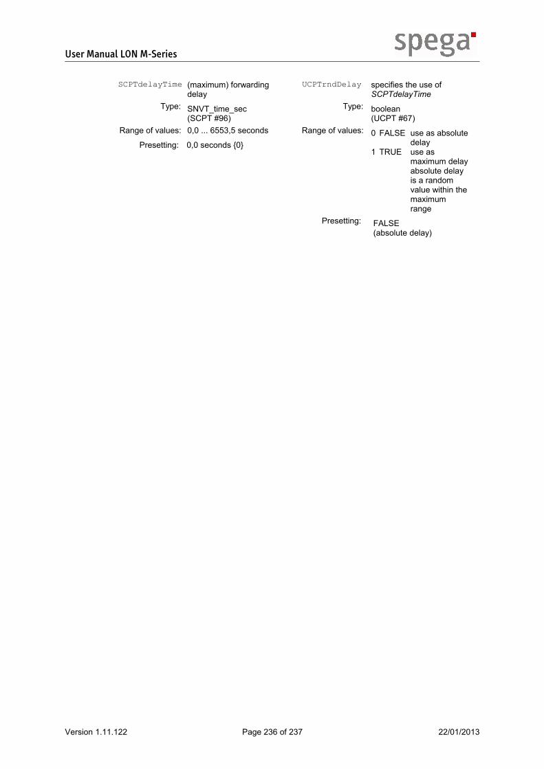
User Manual LON M-Series
SCPTdelayTime (maximum) forwarding delay
Type: SNVT_time_sec (SCPT #96)
Range of values: 0,0 ... 6553,5 seconds
Presetting: 0,0 seconds {0}
UCPTrndDelay specifies the use of SCPTdelayTime
Type: boolean (UCPT #67)
Range of values: 0 FALSE use as absolutedelay
1 TRUE use as maximum delayabsolute delay is a random value within the maximum range
Presetting: FALSE (absolute delay)
Version 1.11.122 Page 236 of 237 22/01/2013

User Manual LON M-Series
5.5. Glossary
AC alternating current
ASK amplitude shift keying
DC direct current
DECT digital enhanced cordless telecommunications
FTT free topology transceiver
functional object functional component of an device application
GSM global system for mobile communications
hex hexadecimal
ID identification number
LAN local area network
LED light emitting diode
LNS LonWorks network services
LON local operating network
LonMark™ International organization with the intention to advance and bring forward the LON technology
Neuron-ID individual, definite 48-bit device number
NV network variable
Plug-in Tool to configure, commission and log components of applications
Resource Files files including definitions of interface components which can be used from network management tools to display and interpret the data properly
SCPT standard configuration property type
SNVT standard network variable type
SMI standard motor interface
SMI-LoVo standard motor interface for low voltage motors (24VDC)
TP twisted pair
UCPT user configuration property type
UNVT user network variable type
Version 1.11.122 Page 237 of 237 22/01/2013


