78
EagleWorks 1.0 User Manual A Complete Reference Book For EagleWorks Software GU Eagle America, Inc. http://www.gueagle.com/

EagleWorks 1.0
User ManualA Complete Reference Book For EagleWorks Software
GU Eagle America, Inc.http://www.gueagle.com/


iii
Contents
List of Figures....................................................................................................................... v
Chapter 1: Install EagleWorks.......................................................................7Get EagleWorks............................................................................................................ 8Install EagleWorks Software........................................................................................ 8Upgrade EagleWorks Software.................................................................................. 11
Chapter 2: Using EagleWorks......................................................................13Get Familiar With EagleWorks.................................................................................. 14Setup Device Connection............................................................................................15Page Settings............................................................................................................... 18Create Basic Designs.................................................................................................. 19Import Complex Design Patterns............................................................................... 21Review Designs...........................................................................................................23Important Concepts You Must Know........................................................................ 27Prepare For Processing............................................................................................... 33Generate And Output Data......................................................................................... 37Save File......................................................................................................................38Summary......................................................................................................................38
Chapter 3: More Edit And Layout Functions............................................ 39Edit Drawing Objects................................................................................................. 40Edit Curves..................................................................................................................43Create Variable Text...................................................................................................44Array............................................................................................................................45Modify Design Layout................................................................................................47Summary......................................................................................................................48
Chapter 4: Functions Specific For Cutting.................................................49Offset Polygon............................................................................................................ 50Remove Overlap......................................................................................................... 50Combine Curve........................................................................................................... 51Close Curve.................................................................................................................52Smooth Curve............................................................................................................. 52
Chapter 5: CAM Related Functions And Settings..................................... 57Optimize Cutting Order.............................................................................................. 58Limit Speed of Small Circle Cutting..........................................................................61Engraving Correction..................................................................................................61Check Data Before Output......................................................................................... 63Additional Output Settings......................................................................................... 64More Settings Of Laser Machine............................................................................... 65Using Rotary Unit.......................................................................................................66

iv Contents
Manage Documents In Laser Machine.......................................................................67Test Basic Movement Functions Of Laser Machine.................................................. 68
Chapter 6: Rarely Used Functions...............................................................69Export.......................................................................................................................... 70Image Library..............................................................................................................70Capture........................................................................................................................ 72
Appendix A: Appendix..................................................................................73TroubleShooting.......................................................................................................... 74Vendor Settings...........................................................................................................74
Revision History.................................................................................................................. 77

v
List of Figures
Figure 1-1: A USB flash drive with EagleWorks software package in it.............................. 8
Figure 2-2: Main user interface of EagleWorks...................................................................14
Figure 2-3: Vector graphics with processing mode set to Cut and Scan..............................29
Figure 2-4: Halftone illustration...........................................................................................30
Figure 2-5: Picture of Hepburn dithered by halftone method.............................................. 31
Figure 2-6: Machine coordinates supported by RDCAM control system............................ 31
Figure 2-7: Programmed coordinates illustration.................................................................32
Figure 3-8: Illustration of nodes and control points of line and curve.................................43
Figure 4-9: Illustration of polygon offset function.............................................................. 50
Figure 4-10: Illustration of combine curve function............................................................ 51
Figure 4-11: Illustration of curve smooth function.............................................................. 52
Figure 5-12: Comparision of a design before and after order optimization......................... 58
Figure 5-13: Illustrate reverse interval compensation and offset repay of engraving...........62

vi List of Figures

7
Chapter
1Install EagleWorks
Topics:
• Get EagleWorks• Install EagleWorks Software• Upgrade EagleWorks
Software
In this chapter, we'll guide you to install EagleWorks, andget ready to use it with your laser machine.

8 Get EagleWorks
Get EagleWorks
Before we dive into EagleWorks installation, you need to get it by the following ways.
Figure 1-1: A USB flash drive with EagleWorks software package in it
Note:
The blue license key shown in the picture above is for EaglePrint, please refer to EaglePrintUser Manual for more information.
1. Buy laser machine from us
We'll provide EagleWorks along with the laser machine. You can visit http://www.gueagle.com/laser-machines.html to get more information about our lasermachines.
2. Get updated release from http://www.gueagle.com/
If you already have EagleWorks and want to check if there is a new release, please checkour website.
Install EagleWorks Software
We'll guide you to install EagleWorks software in this section. Before start, pleaseplug the USB flash drive in or download EagleWorks installation package from http://www.gueagle.com/, as described in Get EagleWorks on page 8.
Browse to and double click on EagleWorksSetup_[version].exe to start installation, you'llsee a dialog shown as below.

1. Install EagleWorks 9
Click on Install button to start processing, shown as below.
After copying prerequisite files to system, you'll see the setup dialog shown as below.
Tip:
You can change display language of the setup dialog by Language option, shown as above.

10 Install EagleWorks Software
If you want to connect to your laser machine by USB cable connection, click on InstallUSB driver button to install USB port communication driver for RDCAM control system.That's not necessary if you plan to connect your laser machine to PC by Ethernet cable.
Tip:
The installer will prompt you to connect RDCAM control system through USB port first,it's safe to ignore it and Windows operating system will install the driver while the first timeyou connect RDCAM through USB port.
Then, choose appropriate setting for Origin and Size unit options for your machine andconvention, and click on Install button to install EagleWorks to your PC.
Tip:
The origin is the resetting position of laser machine, it's usually top-right corner of workingarea of our machines.
If you check Locate install path option in the setup dialog, it will pop up a dialog and helpyou choose installation path, shown as below.
When install finished, click on Exit button to close the setup dialog.
After installation, you'll find a shortcut for EagleWorks in your desktop, shown as below.Double click on it to open EagleWorks software.
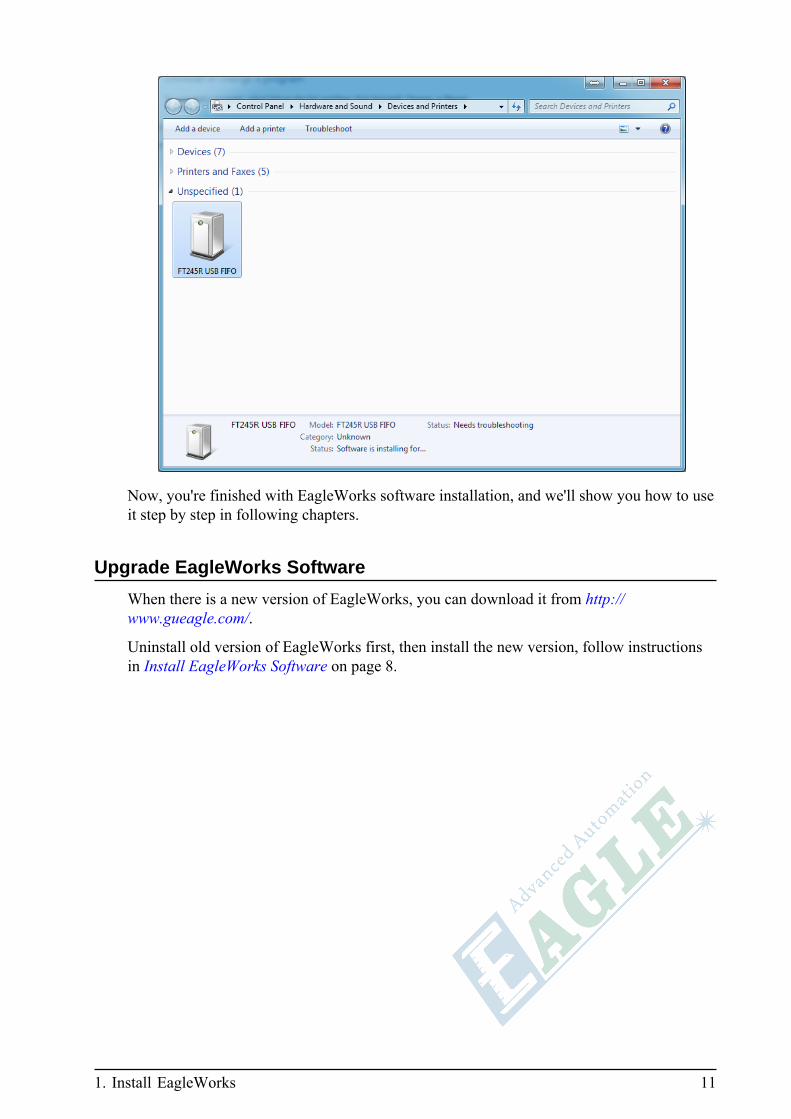
When connect RDCAM control system to your PC by USB cable, you'll see a FT245RUSB FIFO device in Devices and Printers dialog of Windows system, shown as below.That means the USB driver for communication is installed correctly, and the laser machineis ready for receive jobs.
1. Install EagleWorks 11
Now, you're finished with EagleWorks software installation, and we'll show you how to useit step by step in following chapters.
Upgrade EagleWorks Software
When there is a new version of EagleWorks, you can download it from http://www.gueagle.com/.
Uninstall old version of EagleWorks first, then install the new version, follow instructionsin Install EagleWorks Software on page 8.

12 Upgrade EagleWorks Software

13
Chapter
2Using EagleWorks
Topics:
• Get Familiar WithEagleWorks
• Setup Device Connection• Page Settings• Create Basic Designs• Import Complex Design
Patterns• Review Designs• Important Concepts You Must
Know• Prepare For Processing• Generate And Output Data• Save File• Summary
In this chapter, we'll show you how to use EagleWorks stepby step, from setting up connection with your laser machine,setting up page and creating designs, to outputing data tolaser machine.
You'll get familiar with basic functions and operations tofinish simple jobs, and we'll cover more advanced parts insubsequent chapters.
14 Get Familiar With EagleWorks
Get Familiar With EagleWorks
EagleWorks is a specialized CAD/CAM software, cooperated with RDCAM controlsystem, for laser cutting and engraving processing. You can create simple designs, importcomplex patterns, set layout, output data and control processing progress, all in it.
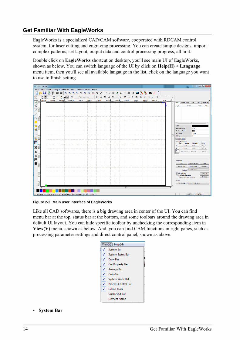
Double click on EagleWorks shortcut on desktop, you'll see main UI of EagleWorks,shown as below. You can switch language of the UI by click on Help(H) > Languagemenu item, then you'll see all available langauge in the list, click on the language you wantto use to finish setting.
Figure 2-2: Main user interface of EagleWorks
Like all CAD softwares, there is a big drawing area in center of the UI. You can findmenu bar at the top, status bar at the bottom, and some toolbars around the drawing area indefault UI layout. You can hide specific toolbar by unchecking the corresponding item inView(V) menu, shown as below. And, you can find CAM functions in right panes, such asprocessing parameter settings and direct control panel, shown as above.
• System Bar
2. Using EagleWorks 15
You can find most commonly used commands on System Bar toolbar, below menu barin default UI layout.
• Draw Bar
You can find commands for creating, editing drawing objects and layout on Draw Bartoolbar, on left side of drawing area in default UI layout.
• Cut Property Bar
You can edit properties of drawing objects on Cut Property Bar toolbar, on top ofdrawing area in default UI layout.
• Arrange Bar
You can find commands for controling objects layout on Arrange Bar toolbar, such asalignments, spacing and position. It's on top of drawing area in default layout.
• Color Bar
You can set drawing objects to colors in Color Bar toolbar, to assign objects to specificlayer. It's on bottom of drawing area in default UI layout.
• System Work Plat
There are six setting groups for different aspects of EagleWorks in System Work Platpane, we'll cover them in more details in following contents. It's on right side of drawingarea in default UI layout.
• Process Control Bar
You can find data output and direct processing control commands on Process ControlBar pane, on right side of drawing area in default UI layout.
Setup Device Connection
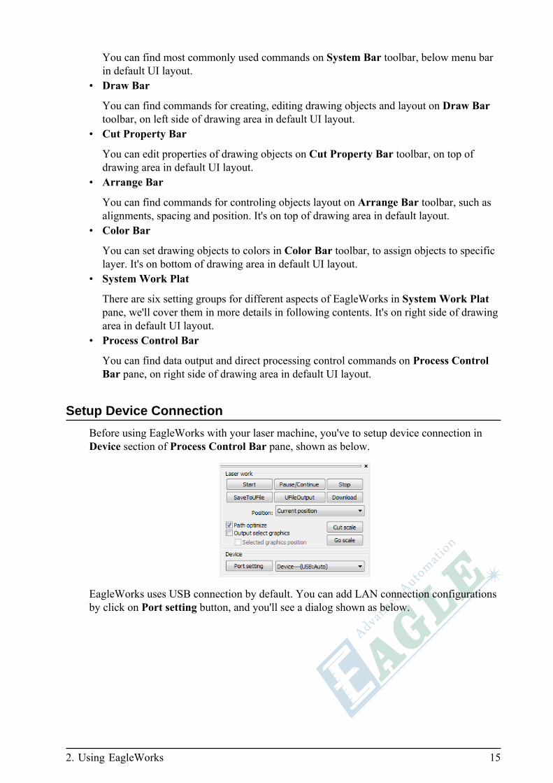
Before using EagleWorks with your laser machine, you've to setup device connection inDevice section of Process Control Bar pane, shown as below.
EagleWorks uses USB connection by default. You can add LAN connection configurationsby click on Port setting button, and you'll see a dialog shown as below.
16 Setup Device Connection
Follow steps below to set up a LAN connection with your laser machine.
1. Connect your laser machine to PC by an Ethernet cable.
You can see Lan ON status indication on control panel of the laser machine whenconnection established.
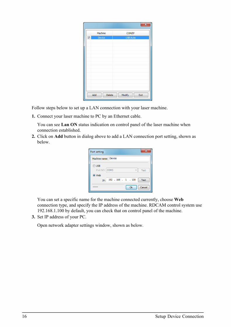
2. Click on Add button in dialog above to add a LAN connection port setting, shown asbelow.
You can set a specific name for the machine connected currently, choose Webconnection type, and specify the IP address of the machine. RDCAM control system use192.168.1.100 by default, you can check that on control panel of the machine.
3. Set IP address of your PC.
Open network adapter settings window, shown as below.

2. Using EagleWorks 17
Right click on the adapter connected to the machine, and choose Properties menu item,you'll see a dialog shown as below.
Choose Internet Protocol Version 4 (TCP/IPv4) and click on Properties button, you'llsee a dialog shown as below.

18 Page Settings
Choose Use the following IP address option, set IP address to 192.168.1.99 andSubnet mask to 255.255.255.0, leave other fields blank, then click OK button toconfirm modifications.
4. Go back to EagleWorks Port setting dialog, and click on Test button, you'll see a dialogtold you that port test succeed.
Tip:
If you have only one laser machine, the simplest way is to connect the machine to your PCby an Ethernet cable directly.
If you have more than one machine, you can use a wireless router to connect all of them atsame time.
1. Set different IP address for each machine on panel.2. Set different name for each machine.3. Set corresponding IP address for each machine in EagleWorks.4. Select corresponding port setting when output to each specific machine.
Be ware that you should set all IP address in same subnet with your PC, like 192.168.1.x.
Now you connected your laser machine to PC, and you can create some designs usingEagleWorks.
Page Settings
Before creating some designs, you've to check and correct page settings according toRDCAM control system settings of your laser machine.
Click on Config(S) > Page Setting menu item to open Page setting dialog, shown asbelow.

2. Using EagleWorks 19
The best way to synchronize page settings with RDCAM control system in laser machineis to enable Auto fresh page setting option and click on Read button to accomplishsynchronization.
Warning:
You can set page size manually, but you may get unpredictable results if the settingsare different with that in RDCAM control system, do it at your own risk.
After synchronizing page settings from RDCAM control system, you can check Page widthand Page height in the dialog.
There're some other useful settings in this dialog. You can enable or disable Grid ofdrawing area, and set GridSpace of it. You can set movement step of keyboard moving ofdrawing objects here. You can set color for background, border of drawing area and lineof grid, as you can do in other CAD softwares. And, you can set position of backgroundimage, and change size of it.
Now, you got a correct page with settings you prefered.
Create Basic Designs
Now, you can create some basic designs using drawing tools of EagleWorks. You can visitdrawing tools by Draw(D) menu or Draw Bar toolbar.
You can draw points, lines, curves, polygons, rectangles, ellipses and texts in EagleWorks,shown as below.

20 Create Basic Designs
When drawing line or polyline, you can press and hold Ctrl key to get horizontal or verticalline segment. You can draw a polyline using curve tool if you don't hold and drag withcontrol point when clicking on drawing area to add new nodes. To finish polyline or curve,you can right click anywhere in drawing area, or left click on the start point of the polylineor curve to close it, the mouse cursor will change to a bold target sign when you got it.
Left click and drag to create recangle or ellipse. Press and hold Ctrl key to get square orcircle, press and hold Shift key to use the left clicked position as center of the rectangle orellipse.
When creating text object, after left clicking on drawing area, you'll see a dialog shown asbelow.
2. Using EagleWorks 21
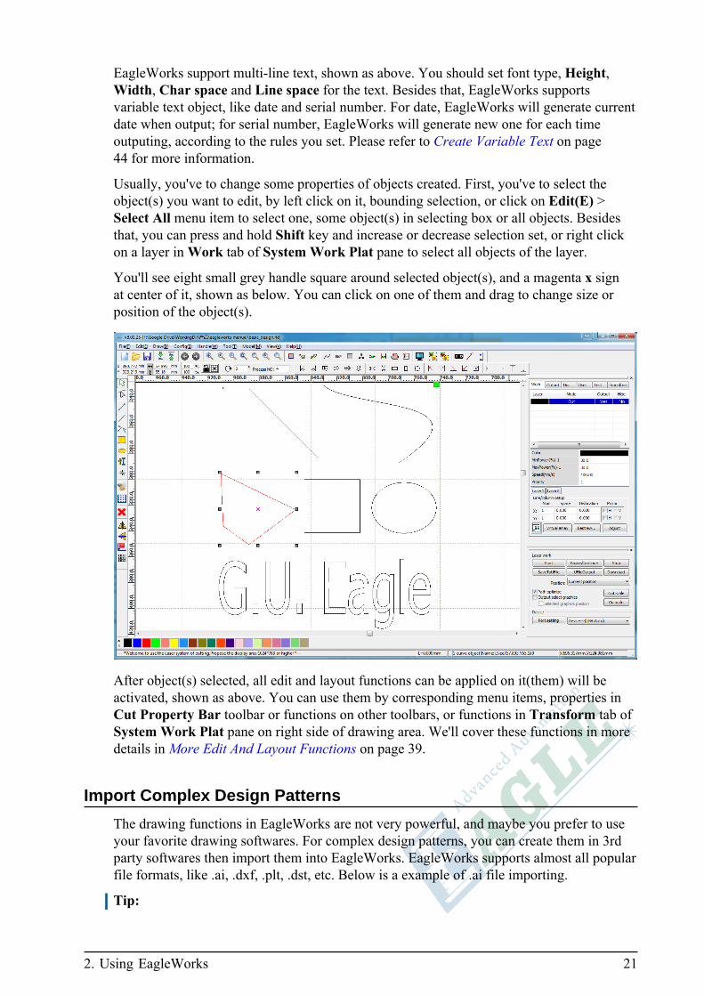
EagleWorks support multi-line text, shown as above. You should set font type, Height,Width, Char space and Line space for the text. Besides that, EagleWorks supportsvariable text object, like date and serial number. For date, EagleWorks will generate currentdate when output; for serial number, EagleWorks will generate new one for each timeoutputing, according to the rules you set. Please refer to Create Variable Text on page44 for more information.
Usually, you've to change some properties of objects created. First, you've to select theobject(s) you want to edit, by left click on it, bounding selection, or click on Edit(E) >Select All menu item to select one, some object(s) in selecting box or all objects. Besidesthat, you can press and hold Shift key and increase or decrease selection set, or right clickon a layer in Work tab of System Work Plat pane to select all objects of the layer.
You'll see eight small grey handle square around selected object(s), and a magenta x signat center of it, shown as below. You can click on one of them and drag to change size orposition of the object(s).
After object(s) selected, all edit and layout functions can be applied on it(them) will beactivated, shown as above. You can use them by corresponding menu items, properties inCut Property Bar toolbar or functions on other toolbars, or functions in Transform tab ofSystem Work Plat pane on right side of drawing area. We'll cover these functions in moredetails in More Edit And Layout Functions on page 39.
Import Complex Design Patterns
The drawing functions in EagleWorks are not very powerful, and maybe you prefer to useyour favorite drawing softwares. For complex design patterns, you can create them in 3rdparty softwares then import them into EagleWorks. EagleWorks supports almost all popularfile formats, like .ai, .dxf, .plt, .dst, etc. Below is a example of .ai file importing.
Tip:

22 Import Complex Design Patterns
EagleWorks only supports some old versions of .ai and .dxf files. If you can not importthese files in some cases, please try to save files in old version and try again.
Click on File(F) > Import... menu item, or click on button on System Bar toolbar, andyou'll see Import dialog shown as below.
Choose the file you want to import, you can see preview of the design pattern in right pane,click on Open button to finish importing, shown as below.
Note:

2. Using EagleWorks 23
For most vector files, design patterns will be imported to corresponding layers accordingto layer descriptions in file. For some special file types, such as DST/DSB files, all designswill be imported to current layer.
If there is something wrong with the imported design, or some part of original design is notoptimized for laser processing, please check import settings first. Click on Config(S) > FilePara Setting menu item to open File Parameter dialog shown as below.
For .plt file, you should set PLT Precision value according to export setting from yourdrawing software. For .dxf file, please confirm DXF Unit option with setting of thedrawing software. EagleWorks can automatically close curves with very small gap, orcombine adjacent lines which are closed enough between end to end, according to settingsof Auto close curves and Combine lines options. And you can set default position forimported design by setting appropriate Docking import data option.
Review Designs
After creating or importing designs, editing them, and adjusting layout finished, you shouldreview all designs to assure everything is ok before generating and outputing data to yourlaser machine.
It's a basic operation and is very useful to zoom in to a specific part of the whole design tocheck details, especially for very complex design. There are many ways to do this, chooseone according to your needs.
1. Zoom to all objects
Click on Edit(E) > View All menu item, or click on button on System Bar toolbar,EagleWorks will zoom all objects to fill the view port, example shown as below.

24 Review Designs
2. Zoom to selected object(s)
Sometimes, you just want to check some selected objects, click on Edit(E) > View DataFrame menu item, or click on button on System Bar toolbar, EagleWorks will zoomselected object(s) to the view port, example shown as below.
3. Zoom to page frame
If you want to check whole page layout, click on Edit(E) > View Page Frame menuitem, or click on button on System Bar toolbar, EagleWorks will zoom page frame toview port, example shown as below.

2. Using EagleWorks 25
4. Zoom to selected drawing area
Sometimes, you want to zoom to some selected drawing area, with or without object(s)in it. Click on Edit(E) > View Select menu item, or click on button on System Bartoolbar, EagleWorks will zoom selected drawing area to the view port, example shownas below.

26 Review Designs
5. General zoom in and zoom out
Click on Edit(E) > ZoomOut or Edit(E) > ZoomIn menu item, or click on or button on System Bar toolbar, EagleWorks will zoom in or zoom out drawing areaaround the point you clicked at.
6. Move view port
Click on Edit(E) > Move menu item, or click on button on System Bar toolbar, thenleft click on any position on drawing area, hold mouse button and drag to move viewport to the position your want.
Besides details of design themselves, EagleWorks can show traveling path of processingprogress. Click on Edit(E) > Show Path menu item, or click on button on System Bartoolbar to trigger traveling path display, example shown as below.

2. Using EagleWorks 27
Important Concepts You Must Know
So far, you're familiar with some basic and design functions of EagleWorks, but you mayhave questions about how EagleWorks mapping your designs to laser processing. Beforestarting preparing for processing and output data in following section, we'll illustrate somemost important concepts in this section, to answer your questions, and help you to useEagleWorks properly.
1. Laser processing modes
First of all, you need to get familiar with laser processing modes if you don't, those'rewhat a laser machine can do on laserable materials. EagleWorks supports laser cuttingand engraving processing modes, you can find definition of laser cutting on Wikipedia.
Laser cutting is a technology that uses a laser to cutmaterials. Laser cutting works by directing the outputof a high-power laser most commonly through optics.A typical commercial laser for cutting materials wouldinvolve a motion control system to follow a CNC or G-code of the pattern to be cut onto the material. The focusedlaser beam is directed at the material, which then eithermelts, burns, vaporizes away, or is blown away by a jet ofgas, leaving an edge with a high-quality surface finish.
https://en.wikipedia.org/wiki/Laser_cutting
Image shown below is a picture of acrylic cut by laser.

28 Important Concepts You Must Know
And you can find definition of laser engraving on Wikipedia too.
Laser engraving, which is a subset of laser marking, isthe practice of using lasers to engrave an object. Thetechnique does not involve the use of inks, nor does itinvolve tool bits which contact the engraving surface andwear out, giving it an advantage over alternative engravingor marking technologies where inks or bit heads have to bereplaced regularly.
https://en.wikipedia.org/wiki/Laser_engraving
Image shown below is a picture of laminates plate engraved by laser.
You can set processing mode in layer processing parameters dialog, triggered by doubleclick one of available layers in Work tab in System Work Plat pane on right side ofdrawing area, refer to Prepare For Processing on page 33 for more information.
2. Vector graphics
EagleWorks supports cutting and engraving on vector graphics, depending on processingmode set for the layer of it. You can find definition of vector graphics on Wikipedia.
Vector graphics is the use of polygons to represent imagesin computer graphics. Vector graphics are based onvectors, which lead through locations called control pointsor nodes. Each of these points has a definite position onthe x- and y-axes of the work plane and determines thedirection of the path; further, each path may be assigned

2. Using EagleWorks 29
various attributes, including such values as stroke color,shape, curve, thickness, and fill.
https://en.wikipedia.org/wiki/Vector_graphics
Example shown below is a logo of G.U. Eagle imported in EagleWorks, there are threelayers in the design, black, blue and red. We set processing mode of blue layer to Scan,which means engraving. You can see it's filled with blue color, and other objects in blackand red are thin outlines.
Figure 2-3: Vector graphics with processing mode set to Cut and Scan
Tip:
By default, objects of layer set to Scan mode will not filled with color in display, youhave to enable it by clicking on Config(S) > Graph Hatch menu item.
3. Raster graphics
EaglePrint supports only engraving on raster graphics, you can find definition of rastergraphics on Wikipedia.
In computer graphics, a raster graphics or bitmap imageis a dot matrix data structure, representing a generallyrectangular grid of pixels, or points of color, viewable viaa monitor, paper, or other display medium. Raster imagesare stored in image files with varying formats.
https://en.wikipedia.org/wiki/Raster_graphics
Most images you see on your computer screen, like pictures found on the Web andphotos you import from your digital camera are raster graphics, stored in JPEG, GIF,PNG and BMP format, etc. You can import them into drawing software for processing.Image shown below is a picture of Audrey Hepburn.
30 Important Concepts You Must Know
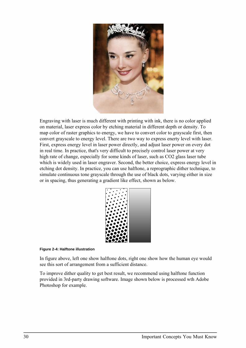
Engraving with laser is much different with printing with ink, there is no color appliedon material, laser express color by etching material in different depth or density. Tomap color of raster graphics to energy, we have to convert color to grayscale first, thenconvert grayscale to energy level. There are two way to express enerty level with laser.First, express energy level in laser power directly, and adjust laser power on every dotin real time. In practice, that's very difficult to precisely control laser power at veryhigh rate of change, especially for some kinds of laser, such as CO2 glass laser tubewhich is widely used in laser engraver. Second, the better choice, express energy level inetching dot density. In practice, you can use halftone, a reprographic dither technique, tosimulate continuous tone grayscale through the use of black dots, varying either in sizeor in spacing, thus generating a gradient like effect, shown as below.
Figure 2-4: Halftone illustration
In figure above, left one show halftone dots, right one show how the human eye wouldsee this sort of arrangement from a sufficient distance.
To improve dither quality to get best result, we recommend using halftone functionprovided in 3rd-party drawing software. Image shown below is processed wth AdobePhotoshop for example.

2. Using EagleWorks 31
Figure 2-5: Picture of Hepburn dithered by halftone method
4. Machine and programmed coordinates
Every laser machine has a virtual coordinates system for it's working area, and you mustsetup machine coordinates used in EaglePrint according to it, shown as below.
Figure 2-6: Machine coordinates supported by RDCAM control system
RDCAM control system supports standard Cartesian coordinates and it's variants, lasermachine manufacture use one of them according to mechanical design. In EagleWorks,you can use Axis Mirror options in System Setting dialog to setup machine coordinatesaccording to that, shown as below.

32 Important Concepts You Must Know
Besides machine coordinates, you can setup programmed coordinates according to yourworkpiece to simplize locating progress, shown as below.
Figure 2-7: Programmed coordinates illustration
To setup programmed coodinates shown in above example, first, move laser head to theposition on workpiece, it's (320, 300) in machine coordinates in this example. Second,for laser machine equipped with RDCAM control system, press Origin button on panel,then control system will setup a programmed coordinates with it's origin (0, 0) set to(320, 300) of machine coordinates. Finally, you've to specify which point on frame ofgraphics will be mapped to programmed origin, using Laser Head option in SystemSetting dialog, shown as above. And you'll see a little green square at the point of allobjects' bounding box, shown as below.

2. Using EagleWorks 33
Prepare For Processing
After design finished, you should review or modify processing parameters, simulateprocessing progress if necessary, to confirm everything is ok, before output data to lasermachine.
EagleWorks supports layered parameter setting, you can specific different layers for objectswhich should be processed with different settings, like processing mode, laser power,speed, etc.

34 Prepare For Processing
In exmaple above, there are three layers in design patterns, black for two big eagle words,blue for upper small string, and red for lower small string. You can find layer parametersettings in Work tab of System Work Plat pane on right side of drawing area, shown asabove.
Click on a layer and you'll see quick settings below the layer list, includes laser power,speed and processing priority. Click on an item to change it's value. If your laser machine isequipped with dual laser, you can switch laser power settings by click on Laser 1 or Laser2 button at bottom.
In layer list, you can see Mode, Output and Hide attribute of each layer. If the Outputattribute of a layer is No, EagleWorks will not generate data for objects in the layer whileoutput data for processing. If the Hide attribute of a layer is Yes, objects in the layer will behidden in the drawing area, and EagleWorks will not generate data for them. Double clickon Output or Hide attribute of a layer will switch it's value.
Double click on Layer color or Mode value will open Layer Parameter settings dialog,shown as below.
There is a small layer list on left side of dialog, you can switch to the layer you want toreview or modify quickly.
Click on Parameter library button to open Parameter library dialog, shown as below.

2. Using EagleWorks 35
You can save parameter set for a specific machine configuration and material combinationto library, or load an exist one from it, greatly simplize setup job, especially for new guyusing your machine.
The part of top left in Layer Parameter dialog include output, Processing Mode, Speedand exhaust blow control options. For Processing Mode, you can set Cut for cutting, orScan for engraving. If you check Default option for Speed, RDCAM control system willuse speed setting saved in it to processing the job.
The part of bottom left is for setting laser power. For laser machine equipped with duallaser, you can control a laser to work or not by enable or disable it here. If you checkDefault button option, RDCAM control system will use laser power settings saved in it toprocessing the job.
Tip:
If you use one PC to send same job to several machines with different configuration, likelaser with different power, maybe it's better to set appropriate settings inside control system,and check Default option for speed and laser power in layer parameters, to use them.
The part on the right is depended on processing mode you set, in dialog shown above, that'sfor advanced cutting, and we'll discuss them later. If you set processing mode to Scan,you'll see dialog shown as below.
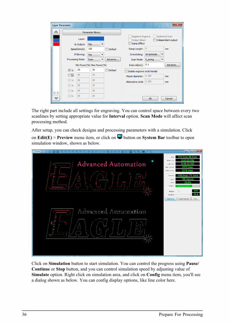
36 Prepare For Processing
The right part include all settings for engraving. You can control space between every twoscanlines by setting appropriate value for Interval option. Scan Mode will affect scanprocessing method.
After setup, you can check designs and processing parameters with a simulation. Clickon Edit(E) > Preview menu item, or click on button on System Bar toolbar to opensimulation window, shown as below.
Click on Simulation button to start simulation. You can control the progress using Pause/Continue or Stop button, and you can control simulation speed by adjusting value ofSimulate option. Right click on simulation area, and click on Config menu item, you'll seea dialog shown as below. You can config display options, like line color here.

2. Using EagleWorks 37
Generate And Output Data
Now you can generate and output data of designs for laser processing. You can controlprocessing progress directly within EagleWorks, or send data to laser machine as an offlinejob.
You can find output functions in Process Control Bar pane on right side of drawing area,shown as below.
If your laser machine is connected with PC, you can use Start, Pause/Continue or Stopfunction to control processing progress directly, or you can use Download functionto download data of designs to laser machine as an offline job, and control processingprogress from the control panel of the machine. If your laser machine is offline, you can useSaveToUFile to save data file to a USB flash disk first, then plug the disk in to the machineand copy file to it.
The laser head of laser machine will stay where it is after processing by default, if you wantto move it to some predefined position, please choose corresponding option for Position. Ifyou choose Absolute coordinate, then designs will be processed in position same as drawnin page.
EagleWorks will apply cutting order optimization on your designs by default, if that's notwhat you want, please uncheck Path optimize option, refer to Optimize Cutting Order onpage 58 for more information.
If you want to output a part of whole designs, you can select the part you want to outputfirst, check Output select graphics option, then EagleWorks will only generate and outputdata of the part to your laser machine.

38 Save File
Before start processing, if you want to confirm the real bounding box of the design on yourlaser machine, you can click on Go scale button, then the machine will drive laser head toshow it to you; or if the data is downloaded to the machine as an offline job, you can pushFrame button on control panel to do that. And you can use Cut scale function to cut aroundthe bounding box of the design.
Save File
After following all these steps to create designs and output data to your laser machine, inmost cases, you'll want to save designs and related settings to file, and reuse it later. Clickon File(F) > Save or File(F) > Save As... menu item, or click on button on System Bartoolbar, you'll see a dialog shown as below.
Set a name for the file and click on Save button to finish, the data of designs will be savedto a file with .rld extension.
Summary
In this chapter, we got familiar with EagleWorks, and got to know the general and basicsteps to use EagleWorks with your laser machine, design, review, setup parameters,generate and output data for laser processing. And we've learned some important conceptsabout laser processing, to use EagleWorks properly.
In subsequent chapters, we'll dive into these steps and functions more deeply, to explorermore advanced features, handle complex use cases, and use EagleWorks more efficiently.

39
Chapter
3More Edit And Layout Functions
Topics:
• Edit Drawing Objects• Edit Curves• Create Variable Text• Array• Modify Design Layout• Summary
In this chapter, we'll cover almost all edit and layoutfunctions, and discuss some advanced feature in moredetails.

40 Edit Drawing Objects
Edit Drawing Objects
You've learned how to create basic designs and import complex design patterns in CreateBasic Designs on page 19 and Import Complex Design Patterns on page 21, but in realproduction jobs, usually you have to do some more advanced editings on drawing objects indesigns. Some editing operatioins, called transformations, only change size, angle, etc, andkeep basic characteristics of object(s), we'll discuss them here one by one in more details.
• Change size of object(s)
When you creating drawing objects in EagleWorks, there's no way to specify exactdimensions for them, you've to modify it later. For design patterns imported intoEagleWorks, you can change their dimensions too.
1. After object(s) selected, you can click, hold and drag grey handles around object(s) tochange it's or theirs' size.
2. If you want to adjust size of object(s) precisely, please select object(s) first, thenchange width or height of the bounding box in Cut Property Bar toolbar. Click on
to maintain the size ratio.3. There is a same function in Transform tab of System Work Plat pane, shown as
below. You can change size of object(s) like in Cut Property Bar toolbar.
The size ratio will be maintained by default, if you want to unlock it, please checkDisproportionate option. Besides modifing size of object(s) selected, you can createa new copy of it(them), by clicking on Apply to copy button. If you change size whencopying, the base point of size increasing or decreasing is according to your selection,shown as above.
4. Sometimes, you have several objects, and you want to resize some of them to samesize with another one. In this case, you can select the object(s) you want to changefirst, then select the other one, at last, click on , or button of Arrange Bartoolbar to set width, height or both of the object(s) same as the one.
• Rotate object(s)

3. More Edit And Layout Functions 41
There're three ways to rotate object(s) in EagleWorks, follow steps below to do it.
1. After object(s) selected, double click on the center x mark and the four handles atcorner of bounding box will switch to rotate mode. Click, hold and drag one of themto rotate the object(s).
2. If you want to rotate object(s) precisely, please select object(s) first, then set rotationangle in Cut Property Bar toolbar.
3. There is a same function in Transform tab of System Work Plat pane, shown asbelow. You can rotate object(s) like in Cut Property Bar toolbar.
This tab provides some more advanced features for rotation. First, you can specifycenter of rotation by entering coodinates for Center. Second, if you want to rotateseveral objects in different angles but using same rotation center, you can selectone of them first, specify center of rotation, and check Lock rotate center option,then the rotation center will be maintained in following rotating operations as youwish. Third, you can simply choose center or eight predefined points of boundingbox of the object(s) selected as rotation center, by cheking Relative center optionand specifing the center, shown as above. At last, you can create a new copy of theobject(s) selected when rotating, by clicking on Apply to copy button.
• Tilt object(s)
There're two ways to tilt object(s) in EagleWorks, follow steps below to do it.
1. After object(s) selected, double click on the center x mark and the four handles atcenter of edges of bounding box will switch to tilting mode. Click, hold and drag oneof them to tilt the object(s).
2. If you want to tilt object(s) more precisely, please select object(s) first, then use tiltfunction in Transform tab of System Work Plat pane, shown as below.
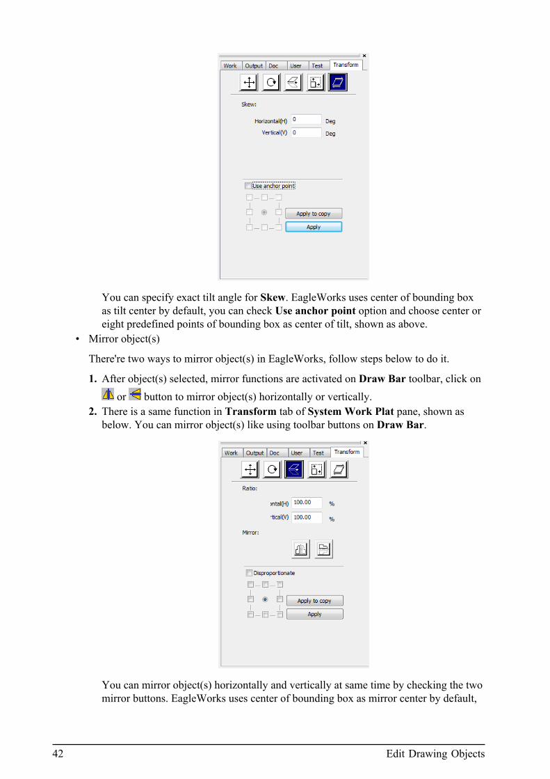
42 Edit Drawing Objects
You can specify exact tilt angle for Skew. EagleWorks uses center of bounding boxas tilt center by default, you can check Use anchor point option and choose center oreight predefined points of bounding box as center of tilt, shown as above.
• Mirror object(s)
There're two ways to mirror object(s) in EagleWorks, follow steps below to do it.
1. After object(s) selected, mirror functions are activated on Draw Bar toolbar, click on or button to mirror object(s) horizontally or vertically.
2. There is a same function in Transform tab of System Work Plat pane, shown asbelow. You can mirror object(s) like using toolbar buttons on Draw Bar.
You can mirror object(s) horizontally and vertically at same time by checking the twomirror buttons. EagleWorks uses center of bounding box as mirror center by default,

3. More Edit And Layout Functions 43
you can change that and choose center or eight predefined points of bounding box ascenter of mirror, shown as above.
Moving drawing object(s), which is related to design layout, will be discussed in ModifyDesign Layout on page 47 later. And there is a commonly used function, besides alloperations covered above, is deletion. After object(s) selected, press Delete key on yourkeyboard, or click on button on Draw Bar toolbar to delete object(s).
Edit Curves
All vector graphics in EagleWorks are composed with line or curve segments, drawn byconnecting nodes which can be edited, except point and text objects. Nodes of curves aredifferent with the ones of lines, with additional control points, shown as below. You canchange basic characteristics by editing these nodes and control points, which is one of themost important functions in modern CAD softwares.
Figure 3-8: Illustration of nodes and control points of line and curve
Click on Draw(D) > Edit Node menu item, or click on button on Draw Bar toolbarto activate node editing tool, you'll see the node editing toolbar appearing on left side ofdrawing area, and mouse cursor will become a black arrow head. Click on a drawing objectto switch it to node editing state, line and curve segments will be turned in to red, and allnodes will be shown as small square handles. Then, click on a node, it will be turned in togreen, and, if it belongs to a curve, all control points will be shown as small black suqarehandles with blue dash lines connected with the corresponding nodes, shown as above.
After node or control point selected, click, hold and drag to move it, EagleWorks willupdate associated line or curve segments in realtime. And, there're more editing functionson node editing toolbar, such as add, delete, etc.
• Add a node to line or curve

44 Create Variable Text
After lines or curves switched in to node editing state, you can move mouse along withit and you'll see a little curve sign under cursor. Click on the position you want to add anode, you'll see a big red square sign displayed, then click on button to add a node atthe position.
• Delete a node on line or curve
After node selected, click on button to delete the node. EagleWorks will updateassociated line or curve segments with it.
Create Variable Text
We've discussed how to create text objects in Create Basic Designs on page 19, and toldyou that there is an additional function to generate variable text objects, we'll show youmore details in this section.
You'll see a dialog shown as below if you check Enable variable text option in the textcreation dialog.
EagleWorks can generate date with some predefined formats in the list shown as above,you can choose appropriate one according to your needs. First, you should choose togenerate Date in the dropdown list, then choose the format you want to use. If you chooseto generate SerialNO, you'll see the dialog shown as below.

3. More Edit And Layout Functions 45
You can set Prefix or Suffix for the serial number, and specify start number and incrementstep according to your needs.
Array
In almost all cases, you will make copies of a design and spread them to fulfill the page,especially for small designs. In EagleWorks, there're two array functions, one will copy andadd real drawing objects, like array functions in all drawing softwares; the other specialone, called virtual array, just embed a piece of information and display virtual drawingobjects.
First, we'll discuss normal array function. Select drawing object(s) first, and click on button on Draw Bar toolbar, you'll see a dialog shown as below.
You can set number of columns and rows you want to copy, and set horizontal and vertical
space between objects. Click on button to change the spreading direction of new copiesof object. Sometimes, if you want to copy and spread objects to fulfill the page, or fulfill aspecific size of area, click on Bestrew... button, and you'll see a dialog shown as below.

46 Array
Specify size of area you want to fill, click Ok button, then EagleWorks will calculate howmany columns and rows to copy automatically according to the size of area and spacesbetween objects.
You can find virtual array functions in Work tab of System Work Plat pane, shown asbelow.
Same method to set array parameters, click on Virtual array to generate array of objects,shown as below.
If you uncheck Config(S) > Show Array menu item, virtual objects will be displayed asplaceholders, shown as below.
If you want to fulfill the page or specific size of area, click on Bestrew... button and set sizeof area as shown above.

3. More Edit And Layout Functions 47
Modify Design Layout
Besides editing objects themselves, you'll do more work on design layouts, such as moving,aligning, etc. There're many ways and functions to do that, we'll discuss on them one byone.
1. After object(s) selected, click, hold and drag x handle at the center of object(s) to moveit.
2. If you want to change position of object(s) precisely, please select object(s) first, thenchange X and Y coordinates of the reference point. You can choose center or eightpredefined points around the bounding box of object(s) as the reference point, byclicking on button on Cut Property Bar toolbar, and you'll see a dialog shown asbelow.
3. There is a same function in Transform tab of System Work Plat pane, shown as below.You can change position of object(s) like in Cut Property Bar toolbar.
You can create a copy of object(s) by clicking on Apply to copy button.4. If you want to move object(s) to a predefined position, like top-left corner of the page,
please select object(s) first, then click on corresponding button on Arrange Bar toolbar,like , according to your needs.
5. If you have several objects, and want to align them in a specific way, please selectobject(s) first, then click on a corresponding button on Arrange Bar toolbar, like ,according to your needs.

48 Summary
6. If there are more than two objects, and you want to average spaces between them, pleaseselect objects first, then click on or button to average horizontal or vertical spacesbetween them.
Summary
In this chapter, we've discussed on all commonly used editing functions, and someadvanced ones, such as editing curves and creating variable texts. Then we learnd the arrayfunctions of EagleWorks, especially the virtual array feature. At last, we show you the waysto change design layouts. After reading this chapter, you can handle almost all commondesign tasks, simple or complex, to finish your job.
In subsequent chapters, we'll discuss on some special features which can be applied onlyon cutting. For engraving, we suggest using 3rd-party softwares like Adobe Photoshop topreprocessing raster images, then import them in to EagleWorks, because same functions inEagleWorks can not generate results as good as them.

49
Chapter
4Functions Specific For Cutting
Topics:
• Offset Polygon• Remove Overlap• Combine Curve• Close Curve• Smooth Curve
In this chapter, we'll discuss some functions specific forlaser cutting processing.

50 Offset Polygon
Offset Polygon
In some use cases, you have a design with two or more nested graphics. When processingwith laser cutting, if you want to avoid conflict between adjacent borders, or reserve a littlegap between them, you should shrink inner contour and extend outer contour of adjacentborders in original designs.
EagleWorks provides a convenient tool to help you to do that. Please select object(s) first,then click on Handle(W) > Offset polygon menu item, or click on button on SystemBar toolbar, you will see a dialog shown as below.
You can set offset distance in this dialog. If you check Delete artwork option, the originaldrawing object(s) will be deleted after operation finished. And you can choose to shrink orextend the polygon(s) selected by checking In or Out option, or do both of them at sametime by checking In+Out option. For nested polygons, you can check Auto In/Out optionto let EagleWorks determines if a polygon should be shrinked or extended automaticallyand smartly, according to it's nest level in design.
Image shown below is a new black polygon offseted from the original red one according tosettings in dialog shown above.
Figure 4-9: Illustration of polygon offset function
Remove Overlap
Sometimes, you'll notice there're some overlapped line segments in polygons of importeddesigns. When cutting, your laser machine will cut at these positions repeatly, and seriouslyreduce processing efficiency.
Usually, these overlapped line segments are very difficult to find out, EagleWorksprovides a special tool to help you doing this job. Please select objects first, then click onHandle(W) > Delete overlap menu item, or click on button on System Bar toolbar,you'll see a dialog shown as below.

4. Functions Specific For Cutting 51
You can check Enable Overlap error option and set Overlap error value to control if theoverlapped line segments should be deleted by checking the distance between them and theoriginal line segments.
Note:
It's a little dangerous operation to delete overlapped line segments, because sometimes youhave no idea of the designer's purpose and opnions. So, please apply this operation verycarefully. We suggest not checking the Enable Overlap error option, and let EagleWorksdetermines what should be deleted automatically.
Combine Curve
Sometimes, there'll be some small gaps between line segments of designs imported toEagleWorks, because some convertsion defects or problems. When cutting with yourlaser machine, you'll get a result of the workpiece with some little connections with sheetmaterial, and can not take it off.
If that's an error, you should remove these little gaps and connect line segments aroundthem. EagleWorks provides a special tool to help you doing this job. Please select objectsfirst, then click on Handle(W) > Combine curve menu item, or click on button onSystem Bar toolbar, you'll see a dialog shown as below.
You can set Combine error in this dialog, and EagleWorks will combine curves if distancebetween their endpoints is smaller than the value you set. Images below shows two linewith 4mm gap between endpoints of them, and we combine them to the new one accordingto settings in dialog shown above.
Figure 4-10: Illustration of combine curve function
52 Close Curve
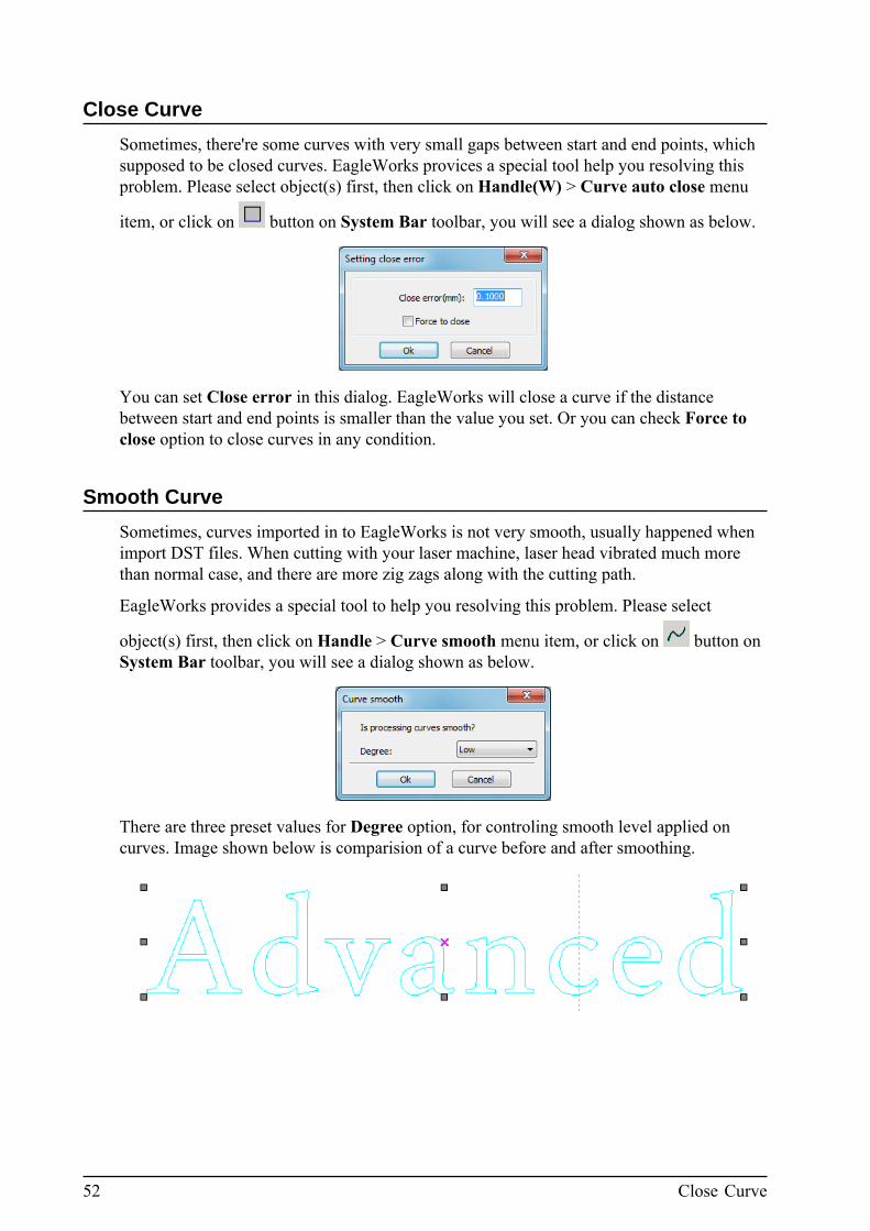
Close Curve
Sometimes, there're some curves with very small gaps between start and end points, whichsupposed to be closed curves. EagleWorks provices a special tool help you resolving thisproblem. Please select object(s) first, then click on Handle(W) > Curve auto close menu
item, or click on button on System Bar toolbar, you will see a dialog shown as below.
You can set Close error in this dialog. EagleWorks will close a curve if the distancebetween start and end points is smaller than the value you set. Or you can check Force toclose option to close curves in any condition.
Smooth Curve
Sometimes, curves imported in to EagleWorks is not very smooth, usually happened whenimport DST files. When cutting with your laser machine, laser head vibrated much morethan normal case, and there are more zig zags along with the cutting path.
EagleWorks provides a special tool to help you resolving this problem. Please select
object(s) first, then click on Handle > Curve smooth menu item, or click on button onSystem Bar toolbar, you will see a dialog shown as below.
There are three preset values for Degree option, for controling smooth level applied oncurves. Image shown below is comparision of a curve before and after smoothing.

4. Functions Specific For Cutting 53
Figure 4-11: Illustration of curve smooth function
If you're not satisfied with the result, you can set Degree to Custom, then press Ok button,and you'll see a dialog shown as below.
Drag Smoothness slider to set custom smooth value first, then press Apply button to showthe result. EagleWorks will show curves before and after processing for comparision,original is shown in black and processed is shown in red, image shown below is anexample.
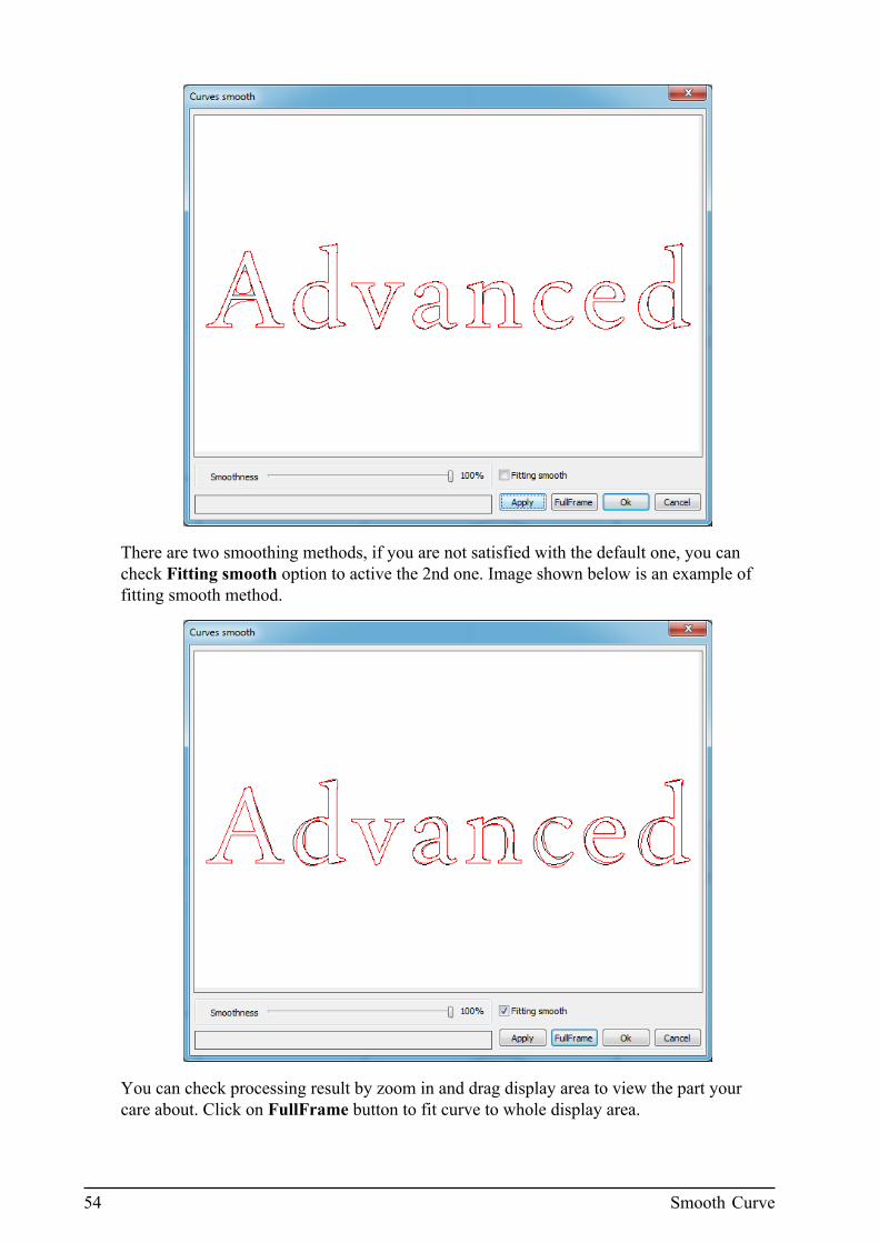
54 Smooth Curve
There are two smoothing methods, if you are not satisfied with the default one, you cancheck Fitting smooth option to active the 2nd one. Image shown below is an example offitting smooth method.
You can check processing result by zoom in and drag display area to view the part yourcare about. Click on FullFrame button to fit curve to whole display area.

4. Functions Specific For Cutting 55
After figuring out best suitable parameters and checking processing result, click on Okbutton to finish operation.

56 Smooth Curve

57
Chapter
5CAM Related Functions And Settings
Topics:
• Optimize Cutting Order• Limit Speed of Small Circle
Cutting• Engraving Correction• Check Data Before Output• Additional Output Settings• More Settings Of Laser
Machine• Using Rotary Unit• Manage Documents In Laser
Machine• Test Basic Movement
Functions Of Laser Machine
In this chapter, we'll discuss functions and settings relatedto CAM, like processing order optimization, laser machineaccessary control settings, etc.

58 Optimize Cutting Order
Optimize Cutting Order
Order of drawing objects in designs in not very important in CAD softwares, but when itcomes to CAM softwares, like EagleWorks in this book, and to laser processing, it becomesvery important, maybe the most important factor which affect efficiency.
EagleWorks provides a tool to handle order optimization automatically. It's a functionalways applied to all drawing objects in designs, so there's no need to select objects first.Click on Handle(W) > Cut optimize menu item, or click on button on System Bartoolbar, you will see a dialog shown as below.
If you want EagleWorks to processing drawing objects in different layers separatelyand one by one, please check Order of layer option. EagleWorks uses a band basedoptimization algorithm to optimize order of drawing objects, so the result is high dependingon size of drawing objects, intersection between bands, and height of bands used foroptimizing. We suggest setting Height of bands to the height of a drawing objects unit plusvertical space between rows, if the design is composed of array of the unit. If the design isvery big and drawing objects spread irregularly, just remember not to set this value too big,which will dramatically slow down the optimization progress.
Image shown below is comparision of a design which is composed of array of a drawingobjects unit, before and after order optimization.
5. CAM Related Functions And Settings 59
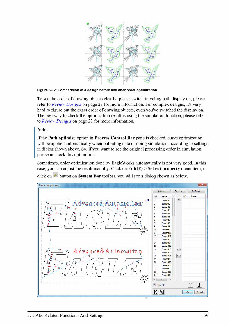
Figure 5-12: Comparision of a design before and after order optimization
To see the order of drawing objects clearly, please switch traveling path display on, pleaserefer to Review Designs on page 23 for more information. For complex designs, it's veryhard to figure out the exact order of drawing objects, even you've switched the display on.The best way to check the optimization result is using the simulation function, please referto Review Designs on page 23 for more information.
Note:
If the Path optimize option in Process Control Bar pane is checked, curve optimizationwill be applied automatically when outputing data or doing simulation, according to settingsin dialog shown above. So, if you want to see the original processing order in simulation,please uncheck this option first.
Sometimes, order optimization done by EagleWorks automatically is not very good. In thiscase, you can adjust the result manully. Click on Edit(E) > Set cut property menu item, orclick on button on System Bar toolbar, you will see a dialog shown as below.

60 Optimize Cutting Order
There is big view port on left side and two ordered drawing objects lists on the right. Theview port is in view mode by default, means you can navigate and review processing orderby some simple mouse operations, like scrolling up and down to zoom in and out, or click,hold and drag to move designs. ShowPath option is checked by default, and you'll seetraveling path in the view port. If you navigate to some part of designs, click on buttonto go back to full view the designs quickly.
EagleWorks will give an ordered name for all drawing objects, and show them in anordered list on left by default. Click on one of them will switch it to selected state, and youcan see it's direction and all nodes in view port, shown as below. Click on Reverse buttonto reverse it's direction. If you want to change it's start node, please click on to switchthe view port to edit mode, then double click one of the nodes to change it to the start node.
It's difficult to select the drawing object you want in the list when there are many objectsin designs, because you can not distinguish them by name, so the best way is to select itdirectly in the view port, by clicking on it or bounding selection, then apply the operationsyou want on it.
If you want to adjust order of a specific drawing object, or some of them, please click on>>> button to move the whole list to the right first, then select the drawing object you wantto adjust, and click on or button to move it upward or downward. If there're fewobjects and you want to rearrange all of them, the better way is to click on >> button tomove them to the right list one by one. At last, if you want to reverse the order of a wholelist, please click on the ReOrder button on top of it.
Tip:
If you want to change direction of a specific drawing object only, you can click onEdit(E) > Set Cut Direction menu item, select the drawing object and double click on it tofinish the job.

5. CAM Related Functions And Settings 61
If you want to change start node of a specific drawing object only, you can click onEdit(E) > Set Cut Direction menu item, select the drawing object and double click on thenode to finish the job.
Limit Speed of Small Circle Cutting
In some cases, there're a lot of small circles in your designs, with some large graphics. Toachieve best cutting quality with efficiency at same time, you should set high cutting speedin layer parameters, and enable Small circle speed limit option in system setting dialogshown as below.
Click on Config(S) > System Setting menu item will trigger this dialog. EagleWorksprovides some default values for a set of circles with small diameter, and you can modify ordelete them, or add your own settings.
After this option is enabled, your laser machine will slow down to the specified speed ifencountering a small circle, and speed up to layer settings with large graphics.
Engraving Correction
Engraving invovles high speed, dual direction line by line scanning movement, motionsystem drive laser head moving forward and backward along with X- or Y-axes. In thisprogress, laser should be triggered simultaneously with position control of laser head. Butunfortunately, there must be some little timing difference between these two executionsubsystem. Combining with very high speed movements, you will get a swept scanlineoffsetting a little with the theoretical position. Even worse, in dual directly engraving, therewill be offsets in opposite direction between every two adjacent scanlines, and you will seelittle jags along with the edge of swept image, shown as below.

62 Engraving Correction
Figure 5-13: Illustrate reverse interval compensation and offset repay of engraving
In figure above, the black line represents theoretical position of a scanline. The Cyan linestands for real positon of scanline swept from left to right, and the green line stands for realposition of scanline swept from right to left. In this example, laser was triggered a little latethan position control of laser head.
The simplest way to solve this problem is to choose X_unilateralism for Scan Modeoption in layer settings, to enable unidirectly engraving. Every scanline will get same offsetlike the cyan line shown above, and align accurately with each other.
But in that way, it'll take much longer to finish the job in same condition compare to dualdirectly engraving, because laser head need to move back to start position after sweepingevery scanline and this progress has no contribution to engraving. EagleWorks provides anengraving correction option in system settings to balance quality and efficiency aspects ofthe progress. Click on Config(S) > System Setting menu item, you'll see dialog shown asbelow.
Check Scanning option to enable engraving correction function, and click on Add... buttonto add a correction item for a specific engraving speed, shown as below.

5. CAM Related Functions And Settings 63
By setting appropriate Reverse interval value, EaglePrint will offset even scanlines a littleto align with previous odd scanline, like the yellow line shown above, which is alignedwith the cyan line after offsetting. You should set different interval values according toengraving speed, because timing difference between laser and position contorl will be alittle different, please follow steps below to test and confirm how much interval to set for aspecific engraving speed.
1. Draw a rectangle with dimension of 100mm x 40mm, and set Processing Mode to Scanin layer settings.
2. Set Reverse interval value to 0.000mm in system settings, and set engraving Intervalin layer settings to a value large enough to seperate adjacent scanlines clearly by humaneye, then engrave the rectangle on a paper card.
3. Measure reverse interval between an odd and the adjacent even scanlines, like the cyanand the green lines shown above. If even scanline is on left side of the odd one, usenegative interval value, otherwise (laser is triggered a little advance than position controlof laser head, happened on some laser machines with CO2 metal laser tube or servomotion system), use positive value. Set reverse interval value and engrave the rectangleon a paper card again, and check if the two adjacent scanlines are aligned accurately. Ifnot, repeat this step until getting result as good as you wish.
Scanlines of engraving will be aligned accurately with appropriate Reverse intervalsetting, but if there is cutting glyphs, scanlines will still disaligned with it, because they'renot in their theoretical position, like the black line shown above. You should set appropriateOffset repay value to solve this problem, get scanlines in theoretical positon like red andorange ones shown as above.
Check Data Before Output
EagleWorks provides a data checking tool to help you find corresponding problems in yourdesigns. Select drawing objects you want to check, then click on Handle(W) > Data check
menu item, or click on button on System Bar toolbar, you'll see a dialog shown asbelow.
Check options you want to check on the objects selected, then click on Check button.EagleWorks will show results in right pane, and select all drawing objects with problems,shown as below. Then, you should check them one by one to resolve all problems.

64 Additional Output Settings
Additional Output Settings
There're some additional output settings for accessaries of laser machine in Output tabof System Work Plat pane, shown as below, we'll discuss about them one by one in thissection.
1. Automatic Feeding
If your laser machine has a automatica feeding accessary, you can set correspondingparameters here. Click on Enable feeding option and set feeding count and distance, etc.
2. Backlash repay optimization
5. CAM Related Functions And Settings 65
Please check this option if there is a gap between start and end points of closed figurewhen cutting.
3. Pen offset
If there is a pen besides laser head of your laser machine, please set pen offset from laserhead here.
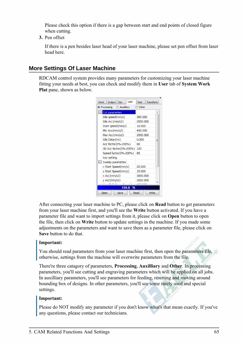
More Settings Of Laser Machine
RDCAM control system provides many parameters for customizing your laser machinefitting your needs at best, you can check and modify them in User tab of System WorkPlat pane, shown as below.
After connecting your laser machine to PC, please click on Read button to get parametersfrom your laser machine first, and you'll see the Write button activated. If you have aparameter file and want to import settings from it, please click on Open button to openthe file, then click on Write button to update settings in the machine. If you made someadjustments on the parameters and want to save them as a parameter file, please click onSave button to do that.
Important:
You should read parameters from your laser machine first, then open the parameters file,otherwise, settings from the machine will overwrite parameters from the file.
There're three catagory of parameters, Processing, Auxilliary and Other. In processingparameters, you'll see cutting and engraving parameters which will be applied on all jobs.In auxilliary parameters, you'll see parameters for feeding, resetting and moving aroundbounding box of designs. In other parameters, you'll see some rarely used and specialsettings.
Important:
Please do NOT modify any parameter if you don't know what's that mean exactly. If you'veany questions, please contact our technicians.
66 Using Rotary Unit
Using Rotary Unit
If there is a rotary unit come with your laser machine, follow steps below to use it withEagleWorks.
1. Move working table down enough to hold rotary with work piece.2. Put rotary unit on working table, parallel to X axis beam, then connect signal wire to the
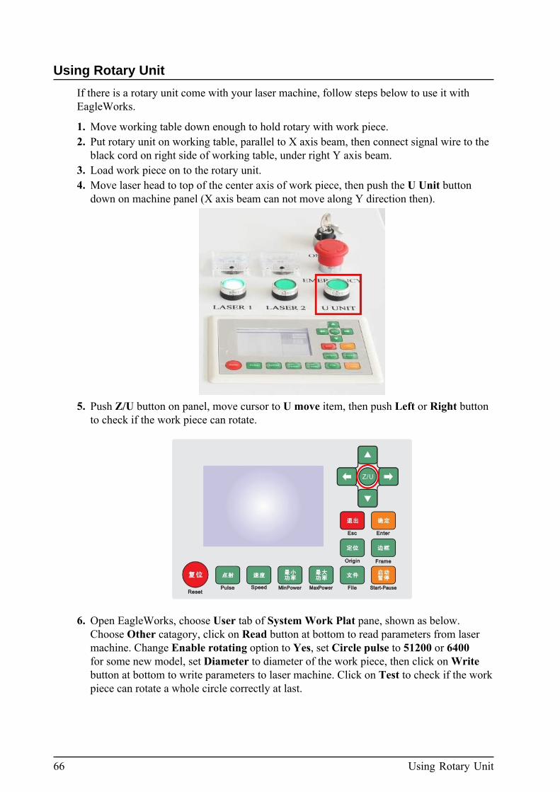
black cord on right side of working table, under right Y axis beam.3. Load work piece on to the rotary unit.4. Move laser head to top of the center axis of work piece, then push the U Unit button
down on machine panel (X axis beam can not move along Y direction then).
5. Push Z/U button on panel, move cursor to U move item, then push Left or Right buttonto check if the work piece can rotate.
6. Open EagleWorks, choose User tab of System Work Plat pane, shown as below.Choose Other catagory, click on Read button at bottom to read parameters from lasermachine. Change Enable rotating option to Yes, set Circle pulse to 51200 or 6400for some new model, set Diameter to diameter of the work piece, then click on Writebutton at bottom to write parameters to laser machine. Click on Test to check if the workpiece can rotate a whole circle correctly at last.

5. CAM Related Functions And Settings 67
7. After all steps above been done, move working table up or down to adjust space betweenwork piece and laser head nozzle to get it ready for processing.
8. Draw something or import designs from file, set processing parameters as what you dofor normal processing, then download job and start processing.
Manage Documents In Laser Machine
If your laser machine is connected with PC, you can manage documents in your lasermachine in EagleWorks. Click on Read button in Doc tab of System Work Plat pane,you'll see the dialog pane shown as below.
In this dialog pane, you can choose a file and apply some operations on it. For example,click on Process button to process the file, or click on Delete button to delete the file, etc.
68 Test Basic Movement Functions Of Laser Machine
Test Basic Movement Functions Of Laser Machine
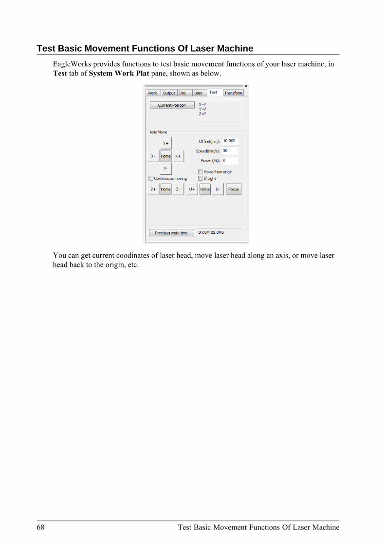
EagleWorks provides functions to test basic movement functions of your laser machine, inTest tab of System Work Plat pane, shown as below.
You can get current coodinates of laser head, move laser head along an axis, or move laserhead back to the origin, etc.
69
Chapter
6Rarely Used Functions
Topics:
• Export• Image Library• Capture
In this chapter, we'll cover some functions rarely used.

70 Export
Export
EagleWorks provide an export function to export vector graphics to .ai or .plt file. Clickon File(F) > Export... menu item or click on button of System Bar, you'll see a dialogshown as below.
Choose file type and specify file name, then click on Save button to export file.
Image Library
EagleWorks provides a function to build and use your own image library. Click onFile(F) > Image library menu item, you'll see a dialog shown as below.

6. Rarely Used Functions 71
Click on New lib button to create a new image library, you'll see a dialog shown as below.
After you create an image library, you can add some images to the library. Select somedrawing objects first, then click on Add Image button, you'll see a dialog shown as below.
Specify an image name and click Ok button to finish. After add some images to the library,you can see them in the preview pane, shown as below.

72 Capture
You can import design patterns as a library.
Capture
You can connect some image recording device like a camera or scanner to your PC, anduse capture function provided by EagleWorks to get image directly. Click on Draw(D) >Capture menu item, or click on button of Draw Bar toolbar, you'll see a dialog shownas below.
Choose the device you want to use and click on Select button to start to capture somethinginteresting.

73
Appendix
AAppendix
Topics:
• TroubleShooting• Vendor Settings
In this chapter, we'll guide you to install all softwarecomponents related to EagleWorks, and get ready to use itwith your laser machine.
74 TroubleShooting
TroubleShooting
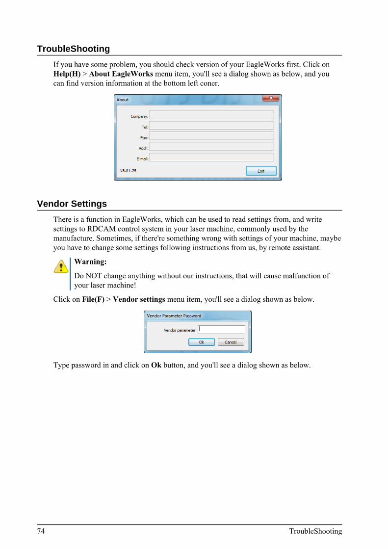
If you have some problem, you should check version of your EagleWorks first. Click onHelp(H) > About EagleWorks menu item, you'll see a dialog shown as below, and youcan find version information at the bottom left coner.
Vendor Settings
There is a function in EagleWorks, which can be used to read settings from, and writesettings to RDCAM control system in your laser machine, commonly used by themanufacture. Sometimes, if there're something wrong with settings of your machine, maybeyou have to change some settings following instructions from us, by remote assistant.
Warning:
Do NOT change anything without our instructions, that will cause malfunction ofyour laser machine!
Click on File(F) > Vendor settings menu item, you'll see a dialog shown as below.
Type password in and click on Ok button, and you'll see a dialog shown as below.

A. Appendix 75
There're four groups of settings listed on left side, click on one of them to show thecorresponding settings. If it's necessary to modify something in settings by yourself, we'llguide you to do that step by step in remote assistant procedure.
Important:
Please reset your laser machine after changing settings!
There're four buttons at bottom, Read, Write, Open and Save. First, click on Read buttonto read settings from your laser machine. If the machine is not connected, you'll see an errordialog, please connect your machine and read again. After reading settings sucessfully fromthe machine, the Write button will be activated. Usually, we'll give you a file to importsettings to your machine, click on Open button to open the file, then click on Write buttonto update settings in your machine.
Important:
Please be sure reading the settings from your laser machine first! If you open file first, thenread settings from your machine, the settings current in your machine will overwrite thesettings from the file.

76 Vendor Settings

77
Revision History
Revision Publication Date Note
1.0 2017/10/25 Initial version of manual.

78


![Operator’s Manual RDWorks/LaserWorks v8 - bosslaser.com v8 Manual.pdf · 2.5.3 Setting File Parameters To invoke the Export dialog box, Click [Menu][File] > [Export], or click the](https://static.documents.pub/doc/80x56/5bda18e209d3f2d8248bfb64/operators-manual-rdworkslaserworks-v8-v8-manualpdf-253-setting-file.jpg)


