38
TCM-R1 Leeb Hardness Tester User Manual

TCM-R1
Leeb Hardness Tester
User Manual

Preface
Hello:
Thank you for your purchase of our Leeb Hardness Tester TCM-R1Series (it is called Hardness Tester below), the Hardness Tester is portable device. It is small in size, light in weight and very easy and fast to take a test. Before using the Hardness Tester you must read this User’s Manual carefully.
The Hardness Tester confirms to the following specifications:
Technical standards for Leeb Hardness Tester, JB/T 9378-2001
Transformation relation of different hardness scales, ISO 18265: 2003


CONTENTS
1 Structure Feature 5
2 Overview 5
3 Preparation & Testing 5
4 Operation in Details 5
5 Servicing & Maintenance 5
6 Malfunction analysis and maintenance 5
7 List of components not warranty 5
8 Instructions for Standard Leeb Hardness Test Specimen 5
Users Notice 5
1 Structure Feature
1.1The body

Front view
1.2 Impact device of type D
1. Release button 2.Plug of the impact device 3.Connection cable 4.Loading tube 5.Guide tube 6.Coil unit 7. Impact body 8.Support

ring
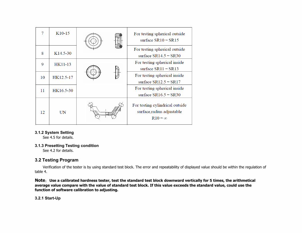
1.3 Some other types of impact device available as options
1.4 Technical Specifications
Error and repeatability of displayed value see Table 1.
Table 1
Type of impact device
DC(D)/DL D+15 C G E

Impacting energy
Mass of impact body
11mJ
5.5g/7.2g
11mJ
7.8g
2.7mJ
3.0g
90mJ
20.0g
11mJ
5.5g
Test tip hardness:
Dia. Test tip:
Material of test tip:
1600HV
3mm
Tungsten
carbide
1600HV
3mm
Tungsten
carbide
1600HV
3mm
Tungsten
carbide
1600HV
5mm
Tungsten
carbide
5000HV
3mm
synthetic
diamond
Impact device diameter:
Impact device length:
Impact device weight:
20mm
75mm
50g
20mm
162mm
80g
20mm
141mm
75g
30mm
254mm
250g
20mm
155mm
80g
Max. hardness of sample 940HV 940HV 1000HV 650HB 1200HV
Mean roughness value of sample surface Ra:
1.6μm 1.6μm 0.4μm 6.3μm 1.6μm
Min. weight of sample:
Measure directly
Need support firmly
Need coupling tightly
>5kg
2~5kg
0.05~2kg
>5kg
2~5kg
0.05~2kg
>1.5kg
0.5~1.5kg
0.02~0.5kg
>15kg
5~15kg
0.5~5kg
>5kg
2~5kg
0.05~2kg
Min. thickness of sample

Coupling tightly
Min. layer thickness for
surface hardening
5mm
≥0.8mm
5mm
≥0.8mm
1mm
≥0.2mm
10mm
≥1.2mm
5mm
≥0.8mm
Size of tip indentation
Hardness
300HV
Indentation
diameter
Depth of
indentation
0.54mm
24μm
0.54mm
24μm
0.38mm
12μm
1.03mm
53μm
0.54mm
24μm
Hardness
600HV
Indentation
diameter
Depth of
indentation
0.54mm
17μm
0.54mm
17μm
0.32mm
8μm
0.90mm
41μm
0.54mm
17μm
Hardness
800HV
Indentation
diameter
Depth of
indentation
0.35mm
10μm
0.35mm
10μm
0.35mm
7μm
--
--
0.35mm
10μm
DC: Test hole G: Test E: Test

Available type of impact
device
or hollow cylindrical;
DL: Test slender
narrow groove
or hole
D+15: Test
groove or slot
surface
C: Test
small, light, thin parts and surface of hardened
layer
large, thick, heavy and rough surface steel
super
high hardness
material
2 Overview
2.1 Features
● Ultra-thin case, making it extremely portable and easy to hold
● Suitable for multiple impact devices and 6 types of hardness scales are available for various applications
● Large and clear digital display
● Ultra-low power dissipation with three AAA batteries powered
2.2 Technical Specification::
● Hardness Scales::HL、 HRC、HRB、HV、HB、HS
● Test Precision:HLD:±6 HRC:±1 HB:±4
● Standard Impact Device: impact device of Type D
● Upper / Lower Limits Setting::(170-960)HLD, (17.9-69.5)HRC, (19-683)HB, (80-1042)HV, (30.6-102.6)HS, (13.5-101.7)HRB
● Optional Impact Device: D/ C /DC / D+15 / DL/ G
● Number of Impact Devices Equipped With One Time: one
● Language:: Chinese/English
● Screen Display: 128X64 dot matrix LCD, backlight and adjustable contrast
● Measuring Direction::360°(down, inclined down, level,inclined up and up)
● Data Memory ::200 readings
● Maximum Hardness of The Measured Work Piece: 940HV(for D,DC,DL,D+15,C impact device)
● Radius of Rurvature of The Measured Work: Rmin=50mm(If using Alien supporting ring, Rmin=10mm)
● Recognition Function::Recognize the type of the impact device by itself
● Measurable Material::Steel and cast steel, alloy tool steel, stainless steel, gray cast iron, nodular cast iron, aluminum casting alloy, copper zinc alloy(brass), copper tin alloy(bronze), fine copper
● Power Supply: 1.5V AAA battery ( 3 PCS)
● Working time: about 150 hours
● Shape Size: 155mm*68mm*27mm
● Weight: 230g
2.3 Main function parameter
● Choose Testing Materials, Hardness Scales, Measuring Direction and times of Tests By Button;
● Direct Display of Hardness Scales including HRB, HRC,HV, HB, HS, HL;
● Show the Result of Each Test Repeated, Automatically or Manually Remove the Wrong Test Results;
● Directly Output the Average Single Test Result or All the Results In One Time;
● Automatic detection of the Battery Voltage, Low Voltage Warning for Battery protection, with Battery Indicating Icon in Test Status;
● Descriptivef Status Bar Display, Buzzer, Error Information, Time, Battery Quantity and so on;
● Ambient temperature:Operating temperature-10~+50℃;

● Storage temperature:-30℃~+60℃.
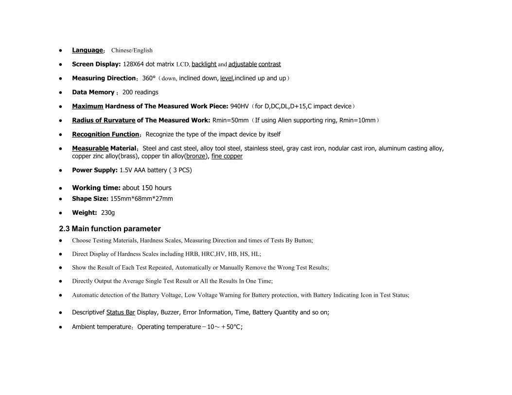
2.4 Testing and measurement range
Table 2 Measurement range
Material
Metho
d
Impact device
D/DC D+15 C G E DL
Steel and cast steel
HRC 17.9~68.5
19.3~67.9
20.0~69.5
22.4~70.7
20.6~68.2
HRB 59.6~99.6
47.7~99.9
37.0~99.9
HRA 59.1~85.8
61.7~88.0
HB 127~651 80~638 80~683 90~646 83~663 81~
646
HV 83~976 80~937 80~996 84~1042 80~950
HS 32.2~99.5
33.3~99.3
31.8~102.1
35.8~102.6
30.6~96.8
Steel HB 143~650
CWT、ST HRC
20.4~67.1
19.8~68.2
20.7~68.2
22.6~70.2
HV 80~898 80~935 100~941
82~1009
Stainless steel
HRB 46.5~101.7
HB 85~655
HV 85~802
GC. IRON
HRC
HB 93~334 92~326
HV
NC、IRON
HRC
HB 131~387
127~364
HV
C.ALUM
HB 19~164 23~210 32~168
HRB 23.8~84.6
22.7~85.0
23.8~85.5
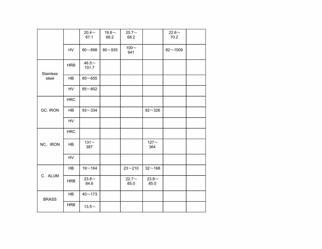
BRASS HB 40~173
HRB 13.5~
95.3
BRONZE HB 60~290
COPPER HB 45~315
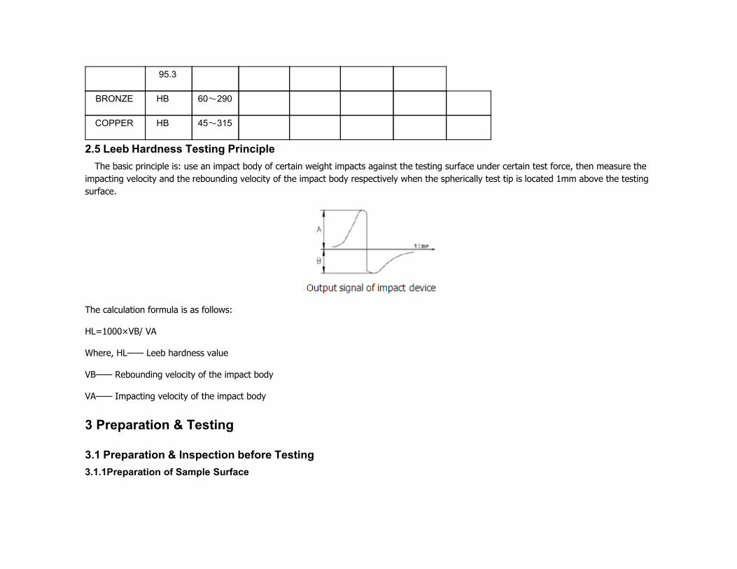
2.5 Leeb Hardness Testing Principle
The basic principle is: use an impact body of certain weight impacts against the testing surface under certain test force, then measure the impacting velocity and the rebounding velocity of the impact body respectively when the spherically test tip is located 1mm above the testing surface.
The calculation formula is as follows:
HL=1000×VB/ VA
Where, HL—— Leeb hardness value
VB—— Rebounding velocity of the impact body
VA—— Impacting velocity of the impact body
3 Preparation & Testing
3.1 Preparation & Inspection before Testing
3.1.1Preparation of Sample Surface

Preparation for sample surface should conform to the relative requirement in the Table 3.
(1) In the preparation processing for sample surface, the hardness effect of being heated or cold processing on the surface of sample should be avoided.
(2)Surface roughness of the measured surface outside the recommended range will cause measurement error. So the surface of the sample to be measured must have the appearance of a metallic luster, smooth, free of scale, paint, rust, etc.
(3)Support of test sample. Support is not necessary for heavy sample of greater than 10lbs. Medium weight parts must be set on flat and stable solid surface e.g. steel table NOT wood. The sample must set absolutely stable on the surface without any wobble or spring.
(4)The sample should have enough thickness, and minimum thickness of sample should conform to Table 3.
(5)For the sample with hardened layer on surface, the depth of hardened layer should conform to Table 3.
(6)Curved surface: The best testing surface of sample is flat. When the curvature
radius R of the surface to be tested is smaller than 30mm (D, DC, D+15,C, E and DL type of impact device) and smaller than 50mm (G type of impact device), the small support ring or the shaped support rings should be chosen.
(7) Coupling. Light-weight sample must be firmly coupled with a heavy base plate. Both coupled surface must be flat and smooth, and there is no redundant coupling agent existing. The impact direction must be vertical to the coupled surface. When the sample is a big plate, long rod or bending piece, it can be deformed and become unstable, even though its weight and thickness is big enough, and accordingly, the test value may not be accurate. So the sample should be reinforced or supported at its back.
(8)Magnetism of the sample itself should be avoided.
Table 3

3.1.2 System Setting See 4.5 for details.
3.1.3 Presetting Testing condition See 4.2 for details.
3.2 Testing Program
Verification of the tester is by using standard test block. The error and repeatability of displayed value should be within the regulation of table 4.
Note:Use a calibrated hardness tester, test the standard test block downward vertically for 5 times, the arithmetical average value compare with the value of standard test block. If this value exceeds the standard value, could use the function of software calibration to adjusting.
3.2.1 Start-Up

(1)Insert the plug of the impact device into the socket of impact device on the tester.
(2)Press key,now power is connected. The instrument is in testing condition.
Table 4:
3.2.2 Loading Pushing the loading-tube downwards until contact is felt. Then allow it to slowly
return to the starting position or using other method locking the impact body.

Chart 1 Chart 2 Chart 3
3.2.3 Localization Press the impact device supporting ring on the surface of the sample firmly, and the impact direction should be vertical to the testing
surface.
3.2.4 Testing (1)Press the release button on the upside of the impact device to test. The sample and the impact device as well as the operator are all required to be stable now.
The action direction should pass the axis of the impact device.
(2)Each measure area of the sample usually need 5 times of testing operation. The result data dispersion should not more than mean value±15HL.
(3)The distance between any two impact points or from the center of any impact point to the edge of testing sample should conform to the regulation of Table 5.
Table 5
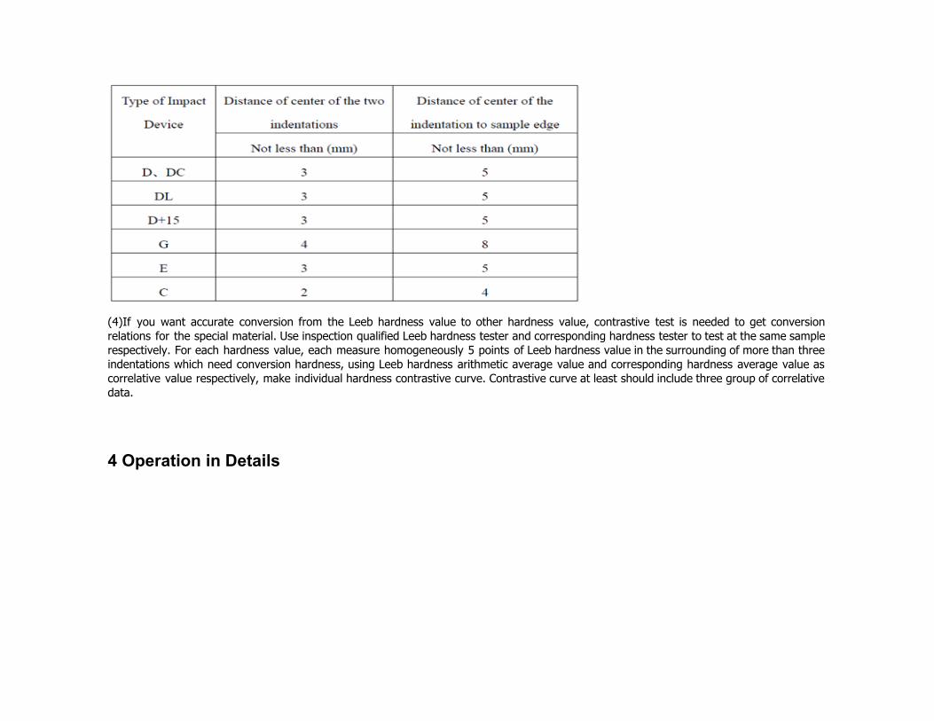
(4)If you want accurate conversion from the Leeb hardness value to other hardness value, contrastive test is needed to get conversion relations for the special material. Use inspection qualified Leeb hardness tester and corresponding hardness tester to test at the same sample respectively. For each hardness value, each measure homogeneously 5 points of Leeb hardness value in the surrounding of more than three indentations which need conversion hardness, using Leeb hardness arithmetic average value and corresponding hardness average value as correlative value respectively, make individual hardness contrastive curve. Contrastive curve at least should include three group of correlative data.
4 Operation in Details

1.LCD Backlight 2. Standby time 3.Silent mode 4.Time display 5. Sign of HL
6. Measure value by HL 7. Battery status 8. Hardness Scale 9.Times 10.Material 11. Measure value 12. Impact direction
Diagrams of the keyboard
Function of the keys:
● Power on/off and LCD brightness on/off.
● Menu/Enter
● Cancel or Escape.
● Direction.
● Material.
● Scale.
● Upward/Save
● Downward/Delete
● Left/Right.
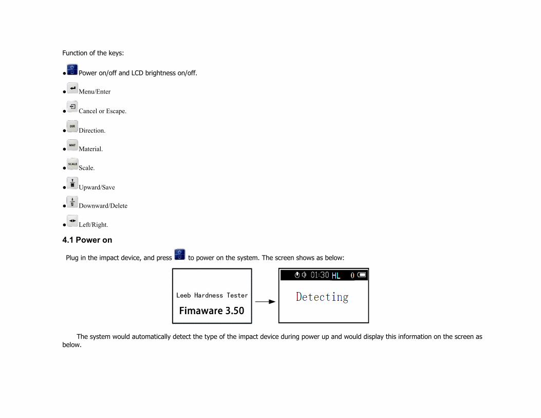
4.1 Power on
Plug in the impact device, and press to power on the system. The screen shows as below:
The system would automatically detect the type of the impact device during power up and would display this information on the screen as below.

Following is the main display interface as below.
4.2 Test Set
Press at the main interface to enter the main menu—Leeb H Tester, as below. Press key or could continuously glance downward or upward.
Press to enter menu “Set parameter”. Press key or to move the cursor to the line you want to set, and press key to enter submenu.
4.2.1 Hard/σ setting
Press key or to move the cursor to the line of “Measure H”,and then press key to switch H/TS continuously.
Note:
1. H is short for Hardness and TS is short for strength.
2. When H/TS is switched to TS, the hardness scale could not be selected.
3. Only D type of impact device has the function of TS measure. So the impact device could not be selected.
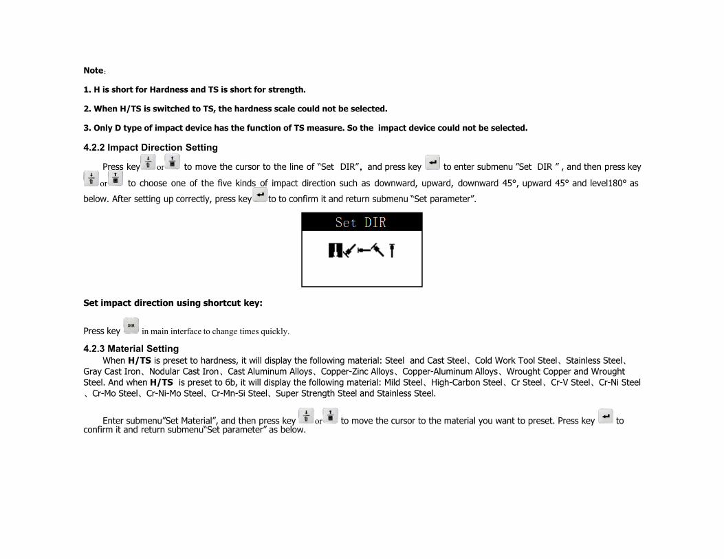
4.2.2 Impact Direction Setting
Press key or to move the cursor to the line of “Set DIR”,and press key to enter submenu ”Set DIR ” , and then press key
or to choose one of the five kinds of impact direction such as downward, upward, downward 45°, upward 45° and level180° as
below. After setting up correctly, press key to to confirm it and return submenu “Set parameter”.
Set impact direction using shortcut key:
Press key in main interface to change times quickly.
4.2.3 Material Setting When H/TS is preset to hardness, it will display the following material: Steel and Cast Steel、Cold Work Tool Steel、Stainless Steel、
Gray Cast Iron、Nodular Cast Iron、Cast Aluminum Alloys、Copper-Zinc Alloys、Copper-Aluminum Alloys、Wrought Copper and Wrought Steel. And when H/TS is preset to бb, it will display the following material: Mild Steel、High-Carbon Steel、Cr Steel、Cr-V Steel、Cr-Ni Steel、Cr-Mo Steel、Cr-Ni-Mo Steel、Cr-Mn-Si Steel、Super Strength Steel and Stainless Steel.
Enter submenu”Set Material”, and then press key or to move the cursor to the material you want to preset. Press key to confirm it and return submenu“Set parameter” as below.
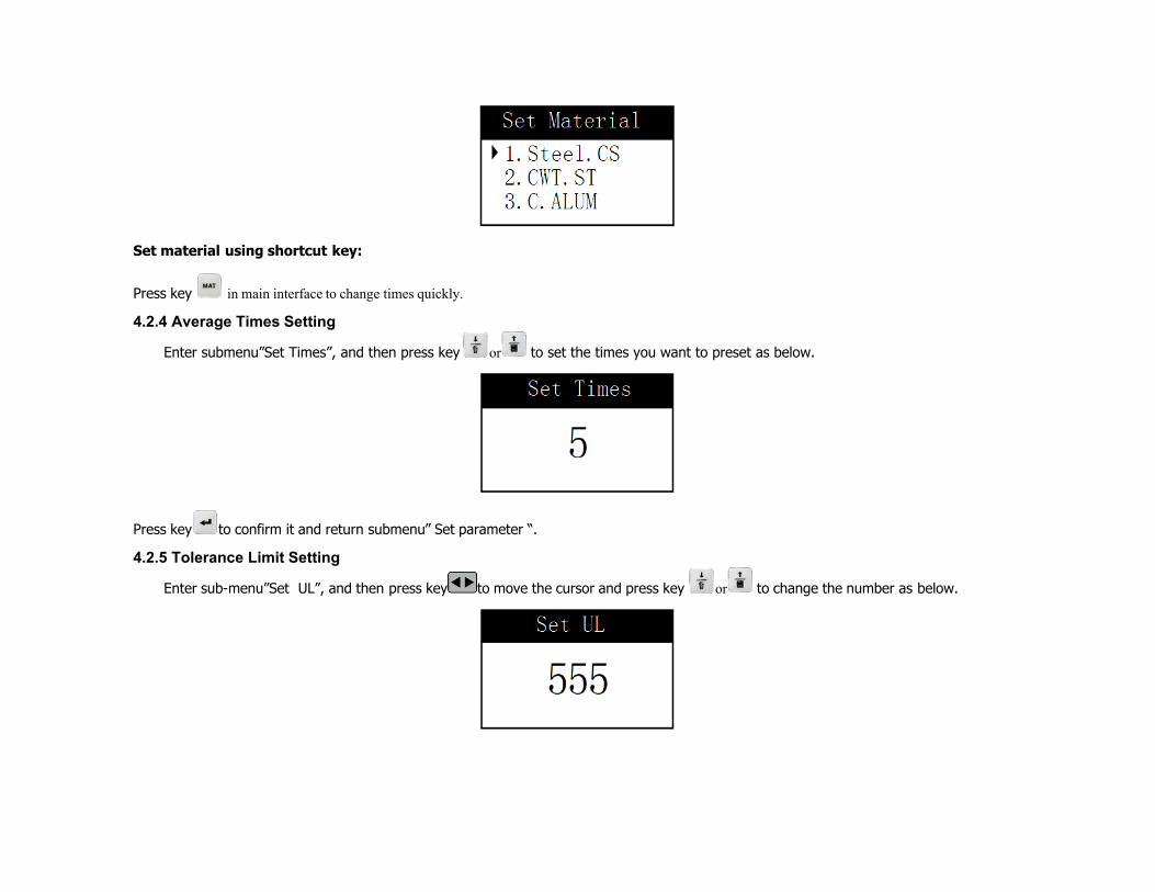
Set material using shortcut key:
Press key in main interface to change times quickly.
4.2.4 Average Times Setting
Enter submenu”Set Times”, and then press key or to set the times you want to preset as below.
Press key to confirm it and return submenu” Set parameter “.
4.2.5 Tolerance Limit Setting
Enter sub-menu”Set UL”, and then press key to move the cursor and press key or to change the number as below.

Press key to confirm it and return sub-menu “Set parameter”.
NOTE:1. UL is short for up limit and LL is short for lower limit.
2. Set LL is the same with UL.
4.2.6 Hardness Scale Setting
Enter submenu ”Set Unit”, and then press key or to move the cursor to the hardness scale you want to preset,as below.
Press key to confirm it and return submenu” Set parameter “.
Set hardness scale using shortcut key:
Press key in main interface to change hardness scale quickly.
4.2.7 Impact device setting
Enter submenu”Set Hammer”, and then press key or to move the cursor to the impact device you want to preset,as below.
Press key to confirm it and return submenu “Set parameter”.
NOTICE: When the “AVE” mark is displayed on the screen, it is invalid to use shortcut key to change parameters. At this time, saving the old result in order to start a new setup is necessary.
4.3 Testing See chapter 3 for details
4.4 Save and Print the data
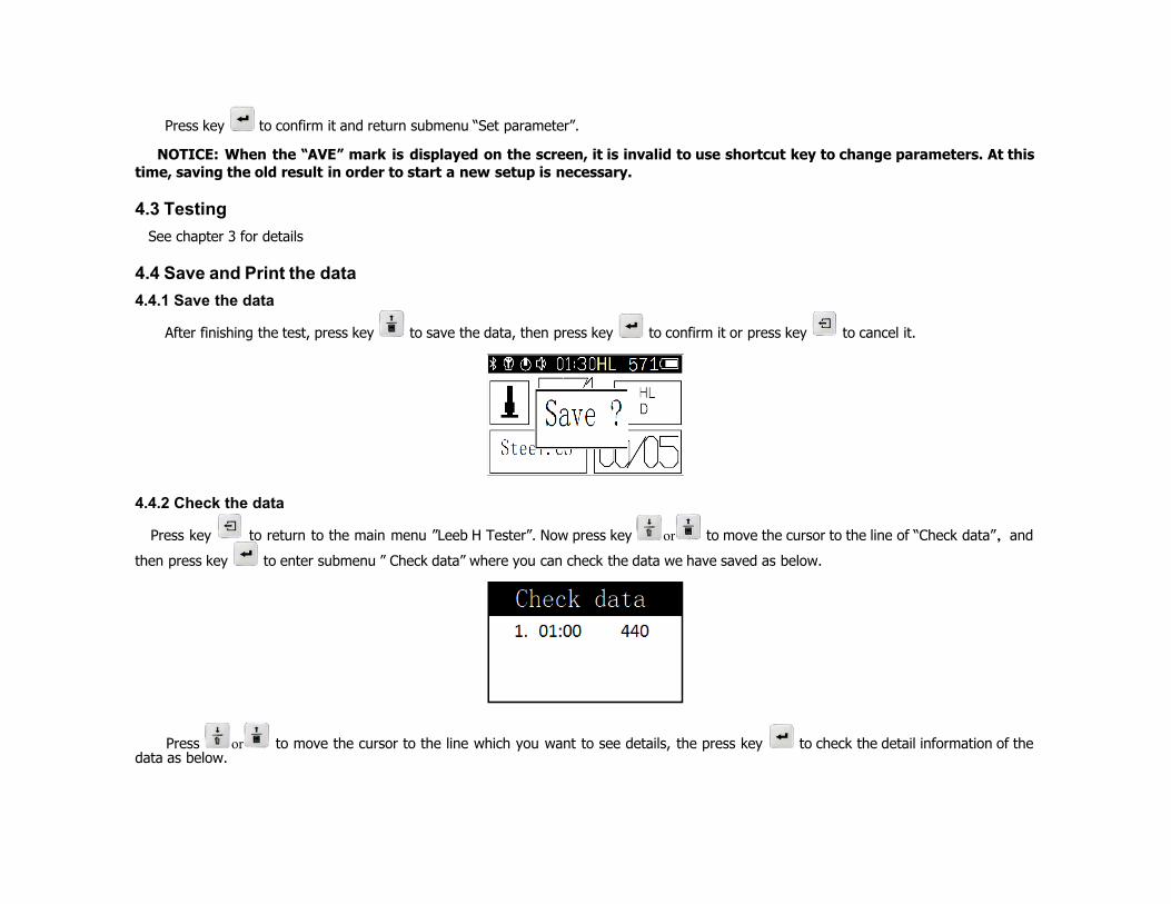
4.4.1 Save the data
After finishing the test, press key to save the data, then press key to confirm it or press key to cancel it.
4.4.2 Check the data
Press key to return to the main menu ”Leeb H Tester”. Now press key or to move the cursor to the line of “Check data”,and
then press key to enter submenu ” Check data” where you can check the data we have saved as below.
Press or to move the cursor to the line which you want to see details, the press key to check the detail information of the data as below.

Press the key to turn the page to check all of the information.
4.4.3 Delete the data
Enter submenu” Check data”, and press key to delete the data, then press key to confirm it or press key to cancel it as below.
4.5 System set
Press the key to return to the main menu ”Leeb H Tester”. Now press key or to move the cursor to the line of “Set system”,
and then press key to enter submenu” Set system” as below.
4.5.1 Time data set
Press key or to move the cursor to the line of “Set time”,and press key to enter submenu” Set time” as below.

Press key to move the cursor and press key or to change the NO. Press key to confirm it and return submenu” Set system “.
4.5.2 Auto power-off
Press key or to move the cursor to the line of “Auto power-off”,and press key to enter submenu” Auto power-off” as below.
Press key or to change the standby time. For example, the digital 1 indicates the standby time is 1 second and the maximum standby time is 10 seconds, while NO.0 indicates standby time is infinite. The Sign shows in the screen when the number is not 0. Press
key to confirm it and return submenu”Set system”.
4.5.3 LCD brightness set
Press key or to move the cursor to the line of “Set Contrast”,and press key to enter submenu” Set Contrast” as below.

Press key or to change the LCD brightness. Press key to confirm it and return submenu ”Set system”.
4.5.4 Silent mode set
Press key or to move the cursor to the line of “Mute? No” and then press key to switch on/off the silent mode continuously as below.
If the silent mode is off, the sign in the screen is or it is .
5 Servicing & Maintenance
5.1 Impact Device Servicing
1) After the impact device has been used for 1000--2000 times, please use the nylon brush provided to clean the guide tube and impact body. When cleaning the guide tube, unscrew the support ring first, then take out the impact body, spiral the nylon brush in counter-clock direction into the bottom of guide tube and take it out for 5-6 times, and then install the impact body and support ring again.
2) Release the impact body after use.
3) Any lubricant is absolutely prohibited inside the impact device.
5.2 Normal Maintenance Program
When using standard Rockwell hardness block to testing, if all the error is bigger than 2 HRC, it may be the invalidation of impacted ball top caused by abrasion. Changing the spherical test tip or impact object should be considered.
When the hardness tester appears some other abnormal phenomena, please do not dismantle or adjust any fixedly assembled parts. Fill in and present the warranty card to us. The warranty service can be carried on.
5.3 The battery
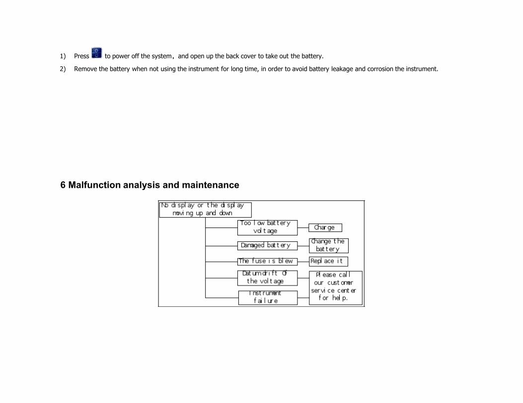
1) Press to power off the system,and open up the back cover to take out the battery.
2) Remove the battery when not using the instrument for long time, in order to avoid battery leakage and corrosion the instrument.
6 Malfunction analysis and maintenance


<1> When using standard Rockwell hardness block to testing, if all the error is bigger than 2HRC, it may be the invalidation of impacted ball top caused by abrasion. Changing the spherical test tip or impact object should be considered.
<2>When the hardness tester appears some other abnormal phenomena, please do not dismantle or adjust any fixedly assembled parts. Fill in and present the warranty card to us. The warranty service can be carried on.
7 List of components not warranty
1 the shell 2 the screen display 3 the panel 4 the impact body 5 the support ring 6 the probe cable 7 the battery(the damage caused by faulty operation problem)

8 Instructions for Standard Leeb Hardness Test Specimen
The Standard Leeb Hardness Test Specimen is a new standard instrument of measurement for hardness measurement used for periodic calibration or daily calibration for the Leeb Tester and the standard have delivered the Leeb Hardness magnitude Since April 1, 2004. We’ll give a brief description of the standard to make you know and use it correctly. The rule for the error of indication and the repeatability of indication of the Leeb Hardness value is listed in table 7, the rule made by the national metrological verification regulations (JJG747-1999) in table 7 is suitable for Leeb Hardness Tester of new, in use and having been repaired.
Error of displayed value: δ= HLD-HLD
In the formula, HLD represents for the average of five measurement values, HLD represents for the hardness value of Standard Leeb Hardness Test Specimen.
Repeatability of displayed value: b= HLDmax-HLDmin
In the formula, HLDmax represents for the maximum value of the five measurement values, HLDmin represents for the minimum value of the five measurement values. The HLD in the two formulas above can also be HLDC,HL(D+15),HLC,HLG and HLE.
Table7: Error and repeatability of displayed value
NO. Type of impact device
Hardness value of Leeb standard hardness block
Error of displayed value
Repeatability of displayed
value
1 D 760±30HLD
530±40HLD
±6 HLD
±10 HLD
6 HLD
10 HLD
2 DC 760±30HLDC
530±40HLDC
±6 HLDC
±10 HLDC
6 HLDC
10 HLDC
3 DL 878±30HLDL
736±40HLDL
±12 HLDL 12 HLDL

4 D+15 766±30HLD+15
544±40HLD+15
±12 HLD+15 12 HLD+15
5 G 590±40HLG
500±40HLG
±12 HLG 12 HLG
6 E 725±30HLE
508±40HLE
±12 HLE 12 HLE
7 C 822±30HLC
590±40HLC
±12 HLC 12 HLC
Users Notice 1. Please fill out the warranty registration card completely. Then mail the copies of the warranty registration card and the invoice within 15 days of receipt of the product to our user service center.
2. If there is a fault or problem within a year after you the instrument please contact us. When you receive an RMA # return the instrument to us with a copy of your warranty registration card and invoice. If you can’t show the warranty registration card and the invoice we would calculate the warranty period from the date the instruments was manufactured, and the warranty period is one year.
3. If it is out of the warranty period, we will assess and repair costs up return of the product to us .
5. Damages caused by transportation, installation, faulty operation, non-professional maintenance are out of warranty service. If you alter the warranty registration car or there is no invoice, the warranty is voided.

Distributed By:
CIMETRIX Ltd.
Address: 1021 SW Klickitat Way, Suite 102
Seattle WA. 98134. USA
Ph: +1-206-340-5995
Fax: +1-206-340-5996
Email: [email protected]
Website: www.leebhardnesstesters.com


