47
manual v1711 | (+34) 968 162 005 | www.sensovant.com | [email protected] USER MANUAL SV-SR05-A1 Analogue second class pyranometer
manual v1711 | (+34) 968 162 005 | www.sensovant.com | [email protected]
USER MANUAL SV-SR05-A1Analogue second class pyranometer

SV-SR05 -A1 manual v1711 2/49
Warning statements
For proper instrument grounding: use SV-SR05 with its original factory-made SR05 cable. See chapter on grounding and use of the shield.
Putting more than 12 Volt across the sensor wiringcan lead to permanent damage to the sensor.
Do not use “open circuit detection” when measuring the sensor output.

3/49
ContentsWarning statements 2 Contents 3 List of symbols 4 Introduction 5 1 Ordering and checking at delivery 8 1.1 Ordering SV-SR05 8 1.2 Included items 9 1.3 Quick instrument check 10 2 Instrument principle and theory 11 3 Specifications of SV-SR05-A1 14 3.1 Specifications SV-SR05 -A1 14 3.2 Dimensions of SV-SR05 -A1 17 4 Standards and recommended practices for use 18 4.1 Classification standard 18 4.2 General use for solar radiation measurement 18 4.3 General use for sunshine duration measurement 18 4.4 Specific use for outdoor PV system performance testing 19 4.5 Specific use in meteorology and climatology 20 5 Installation of SV-SR05-A1 21 5.1 Site selection and installation 21 5.2 Mounting and levelling SV-SR05 22 5.3 Installing SV-SR05 22 5.4 Installing SV-SR05 with its ball levelling and tube mount 23 5.5 Placing and removing SV-SR05’s ball levelling shim 25 5.6 Electrical connection of SV-SR05 -A1 27 5.7 Grounding and use of the shield 27 5.8 Using SV-SR05 -A1’s analogue millivolt ouput 28 6 Making a dependable measurement 29 6.1 The concept of dependability 29 6.2 Reliability of the measurement 30 6.3 Speed of repair and maintenance 31 6.4 Uncertainty evaluation 31 7 Maintenance and trouble shooting 34 7.1 Recommended maintenance and quality assurance 34 7.2 Trouble shooting 35 7.3 Calibration and checks in the field 36 7.4 Data quality assurance 37 8 Appendices 39 8.1 Appendix on cable extension / replacement 39 8.2 Appendix on tools for SV-SR05 -A1 41 8.3 Appendix on spare parts for SV-SR05 -A1 41 8.4 Appendix on standards for classification and calibration 42 8.5 Appendix on calibration hierarchy 43 8.6 Appendix on meteorological radiation quantities 44 8.7 Appendix on ISO and WMO classification tables 45 8.8 Appendix on definition of pyranometer specifications 46 8.9 Appendix on terminology / glossary 47 8.10 EU declaration of conformity 48
SV-SR05 -A1 manual v1711

4/49
List of symbolsQuantities Symbol Unit
Voltage output U VSensitivity S V/(W/m2)Solar irradiance E W/m2
Temperature T °CElectrical resistance Re ΩSolar radiant exposure H W∙h/m2
Time in hours h h
(see also appendix 8.6 on meteorological quantities)
Subscripts
Not applicable
SV-SR05 -A1 manual v1711
5/49
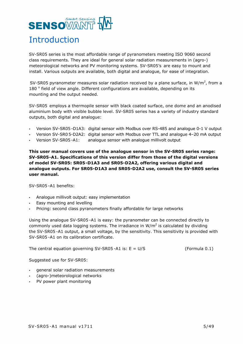
IntroductionSV-SR05 series is the most affordable range of pyranometers meeting ISO 9060 second class requirements. They are ideal for general solar radiation measurements in (agro-)meteorological networks and PV monitoring systems. SV-SR05’s are easy to mount and install. Various outputs are available, both digital and analogue, for ease of integration.
SV-SR05 pyranometer measures solar radiation received by a plane surface, in W/m2, from a 180 o field of view angle. Different configurations are available, depending on its mounting and the output needed.
SV-SR05 employs a thermopile sensor with black coated surface, one dome and an anodised aluminium body with visible bubble level. SV-SR05 series has a variety of industry standard outputs, both digital and analogue:
• Version SV-SR05-D1A3: digital sensor with Modbus over RS-485 and analogue 0-1 V output• Version SV-SR05-D2A2: digital sensor with Modbus over TTL and analogue 4–20 mA output• Version SV-SR05-A1: analogue sensor with analogue millivolt output
This user manual covers use of the analogue sensor in the SV-SR05 series range: SV-SR05-A1. Specifications of this version differ from those of the digital versions of model SV-SR05: SR05-D1A3 and SR05-D2A2, offering various digital and analogue outputs. For SR05-D1A3 and SR05-D2A2 use, consult the SV-SR05 series user manual.
SV-SR05 -A1 benefits:
• Analogue millivolt output: easy implementation • Easy mounting and levelling• Pricing: second class pyranometers finally affordable for large networks
Using the analogue SV-SR05 -A1 is easy: the pyranometer can be connected directly to commonly used data logging systems. The irradiance in W/m2 is calculated by dividing the SV-SR05 -A1 output, a small voltage, by the sensitivity. This sensitivity is provided with SV-SR05 -A1 on its calibration certificate.
The central equation governing SV-SR05 -A1 is: E = U/S (Formula 0.1)
Suggested use for SV-SR05:
• general solar radiation measurements• (agro-)meteorological networks• PV power plant monitoring
SV-SR05 -A1 manual v1711

6/49
Optionally SV-SR05 has a unique ball levelling mechanism with or without tube mount, for easy installation.
Figure 0.1 On the left SV-SR05-A1 analogue second class pyranometer with bubble level and M12-A cable connector in its standard configuration (3 metre cable standard included); on the right SV-SR05 -A1 with optional ball levelling, for easy mounting and levelling on (non-)horizontal surfaces (included mounting screws not displayed)
Figure 0.2 SV-SR05 -A1 analogue second class pyranometer with optional ball levelling and tube mount for easy mounting and levelling on a tube (tube not included)
All SV-SR05 versions should be used in accordance with the recommended practices of ISO, WMO and ASTM.
SV-SR05 -A1 manual v1711
7/49
The ASTM E2848 “Standard Test Method for Reporting Photovoltaic Non-Concentrator System Performance” (issued end 2011) confirms that a pyranometer is the preferred instrument for PV system performance monitoring. SV-SR05 -A1 pyranometer complies with the requirements of this standard. For more information, see our pyranometer selection guide.
WMO has approved the “pyranometric method” to calculate sunshine duration from pyranometer measurements in WMO-No. 8, Guide to Meteorological Instruments and Methods of Observation. This implies that SV-SR05 -A1 may be used, in combination with appropriate software, to estimate sunshine duration. This is much more cost-effective than using a dedicated sunshine duration sensor. Ask for our application note.
SV-SR05 -A1 manual v1711

8/49
1 Ordering and checking at delivery
1.1 Ordering SR05
There is one standard configuration for SR05-A1:• SV-SR05 -A1: with analogue millivolt output
standard cable length: 3 metres
Common options are:• longer cable (10, 20 metres). Specify total cable length• extension cable with connector pair (10, 20 metres). Specify total cable length• ball levelling• tube mount with ball levelling (for tube diameters 25 to 40 mm)
Ball levelling and tube mount are suited for retrofitting.
Table 1.1.1 Ordering codes for SV-SR05 -A1
VERSIONS OF SV-SR05 -A1 (part numbers), without cable
SV-SR05 -A1 analogue second class pyranometer, with millivolt output
analogue second class pyranometer, with millivolt output,with ball levelling
SV-SR05
SV-SR05-A1-BL
-A1-TMBL analogue second class pyranometer, with millivolt output,with tube mount on ball levelling
CABLE FOR SV-SR05, with female M12-A connector at sensor end, non-stripped on other end
‘-03’ after SV-SR05 part number standard cable length: 3 m‘-10’ after SV-SR05 part number cable length: 10 m‘-20’ after SV-SR05 part number cable length: 20 m
CABLE EXTENSION FOR SV-SR05 , with male and female M12-A connectors
C06E-10 cable length: 10 mC06E-20 cable length: 20 m
An extension cable (with connector pair) can be used in combination with a regular cable (with one connector at sensor end) to make alternative SV-SR05 cable lengths possible.
Example: Cable length needed: 15 m. In this case, it is easiest to buy SV-SR05 with a 20 m cable and to cut it to desired length.
Example: Cable length needed: 30 m. In this case, it is easiest to buy SV-SR05 with 10 m cable and a cable extension of 20 m.
SV-SR05 -A1 manual v1711
9/49
1.2 Included items
Arriving at the customer, the delivery should include:
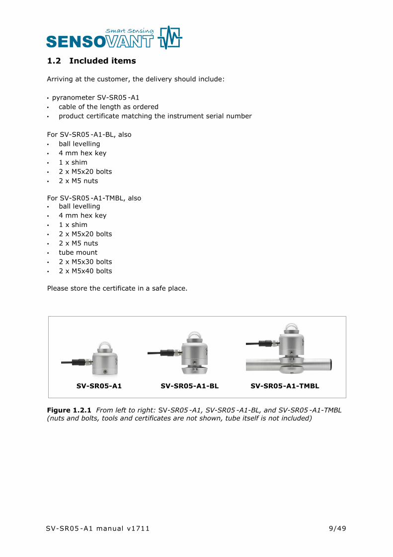
• pyranometer SV-SR05 -A1• cable of the length as ordered• product certificate matching the instrument serial number
For SV-SR05 -A1-BL, also• ball levelling• 4 mm hex key• 1 x shim• 2 x M5x20 bolts• 2 x M5 nuts
For SV-SR05 -A1-TMBL, also• ball levelling• 4 mm hex key• 1 x shim• 2 x M5x20 bolts• 2 x M5 nuts• tube mount• 2 x M5x30 bolts• 2 x M5x40 bolts
Please store the certificate in a safe place.
SV-SR05-A1 SV-SR05-A1-BL SV-SR05-A1-TMBL
Figure 1.2.1 From left to right: SV-SR05 -A1, SV-SR05 -A1-BL, and SV-SR05 -A1-TMBL(nuts and bolts, tools and certificates are not shown, tube itself is not included)
SV-SR05 -A1 manual v1711

10/49
1.3 Quick instrument check
A quick test of the instrument can be done by using a simple handheld multimeter and a lamp.
1. Check the electrical resistance of the sensor between the grey (-) and white (+) wire. Use a multimeter at the 200 Ω range. Measure the sensor resistance first with one polarity, than reverse the polarity. Take the average value. The typical resistance of the wiring is 0.1 Ω/m. The measured resistance should be the typical sensor resistance of 40 to 80 Ω plus 1 Ω for the total resistance of two wires (back and forth) of each 3 m. Infinite resistance indicates a broken circuit; zero or a low resistance indicates a short circuit.2. Check if the sensor reacts to light: put the multimeter at its most sensitive range of DC voltage measurement, typically the 100 x 10-3 VDC range or lower. Expose the sensor to a strong light source, for instance a 100 W light bulb at 0.1 m distance. The signal should read > 2 x 10⁻³ V now. Darken the sensor either by putting something over it or switching off the light. The instrument voltage output should go down and within one minute approach 0 V.3. If applicable, remove the optional sun screen, using the hex key (see chapter on installation of the sun screen). Inspect the bubble level. 4. Inspect the instrument for any damage.
SV-SR05 -A1 manual v1711
11/49
2 Instrument principle and theory
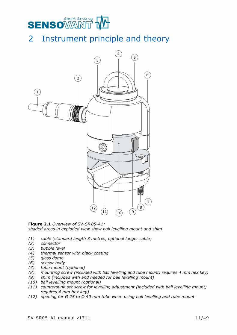
Figure 2.1 Overview of SV-SR 05-A1:shaded areas in exploded view show ball levelling mount and shim
(1) cable (standard length 3 metres, optional longer cable)(2) connector(3) bubble level(4) thermal sensor with black coating(5) glass dome(6) sensor body(7) tube mount (optional)(8) mounting screw (included with ball levelling and tube mount; requires 4 mm hex key)(9) shim (included with and needed for ball levelling mount)(10) ball levelling mount (optional)(11) countersunk set screw for levelling adjustment (included with ball levelling mount;
requires 4 mm hex key)(12) opening for Ø 25 to Ø 40 mm tube when using ball levelling and tube mount
1
2
3
45
6
78
1011 912
SV-SR05 -A1 manual v1711

12/49
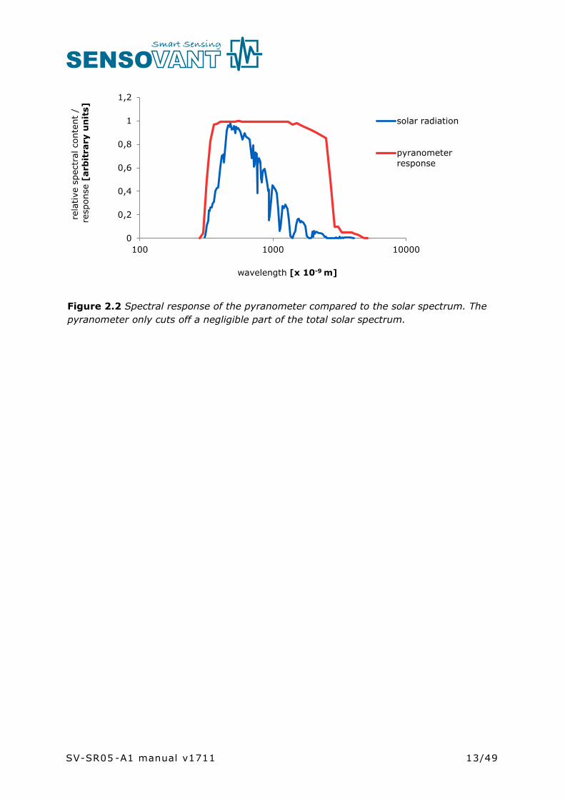
SV-SR05’s scientific name is pyranometer. A pyranometer measures the solar radiation received by a plane surface from a 180 ° field of view angle. This quantity, expressed in W/m2, is called “hemispherical” solar radiation. The solar radiation spectrum extends roughly from 285 to 3000 x 10-9 m. By definition a pyranometer should cover that spectral range with a spectral selectivity that is as “flat” as possible.
In an irradiance measurement by definition the response to “beam” radiation varies with the cosine of the angle of incidence; i.e. it should have full response when the solar radiation hits the sensor perpendicularly (normal to the surface, sun at zenith, 0 ° angle of incidence), zero response when the sun is at the horizon (90 ° angle of incidence, 90 °zenith angle), and 50 % of full response at 60 ° angle of incidence.A pyranometer should have a so-called “directional response” (older documents mention “cosine response”) that is as close as possible to the ideal cosine characteristic.
In order to attain the proper directional and spectral characteristics, a pyranometer’smain components are:
• a thermal sensor with black coating. It has a flat spectrum covering the 200 to 50000 x 10-9 m range, and has a near-perfect directional response. The coating absorbs all solar radiation and, at the moment of absorption, converts it to heat. The heat flows through the sensor to the sensor body. The thermopile sensor generates a voltage output signal that is proportional to the solar irradiance.
• a glass dome. This dome limits the spectral range from 285 to 3000 x 10-9 m (cutting off the part above 3000 x 10-9 m), while preserving the 180 ° field of view angle. Another function of the dome is that it shields the thermopile sensor from the environment (convection, rain).
Pyranometers can be manufactured to different specifications and with different levels of verification and characterisation during production. The ISO 9060 - 1990 standard, “Solar energy - specification and classification of instruments for measuring hemispherical solar and direct solar radiation”, distinguishes between 3 classes; secondary standard (highest accuracy), first class (second highest accuracy) and second class (third highest accuracy).
From second class to first class and from first class to secondary standard, the achievable accuracy improves by a factor 2.
SV-SR05 -A1 manual v1711
13/49
Figure 2.2 Spectral response of the pyranometer compared to the solar spectrum. The pyranometer only cuts off a negligible part of the total solar spectrum.
0
0,2
0,4
0,6
0,8
1
1,2
100 1000 10000
rela
tive
spe
ctra
l con
tent
/re
spon
se[a
rbit
rary
un
its]
wavelength [x 10-9 m]
solar radiation
pyranometer response
SV-SR05 -A1 manual v1711
14/49
3 Specifications of SV-SR05-A1
3.1 Specifications SV-SR05-A1
SV-SR05 -A1 measures the solar radiation received by a plane surface from a 180 o field of view angle. This quantity, expressed in W/m2, is called “hemispherical” solar radiation.
SV-SR05 -A1 offers irradiance in W/m2 as an analogue millivolt output. SV-SR05 -A1 is a passive sensor and does not need a power supply. It can be connected directly to commonly used data logging systems. The irradiance in W/m2 is calculated by dividing the SV-SR05 -A1output, a small voltage, by the sensitivity. This sensitivity is provided with SV-SR05 -A1 on its calibration certificate.
This user manual covers use of the analogue sensor in the SV-SR05 series range: SV-SR05-A1. Specifications of this version differ from those of the digital versions of model SV-SR05: SV-SR05-D1A3 and SV-SR05-D2A2, offering various digital and analogue outputs. For SV-SR05-D1A3 and SV-SR05-D2A2 use, consult the SV-SR05series user manual.
The instrument is classified according to ISO 9060 and should be used in accordance with the recommended practices of ISO, IEC, WMO and ASTM.
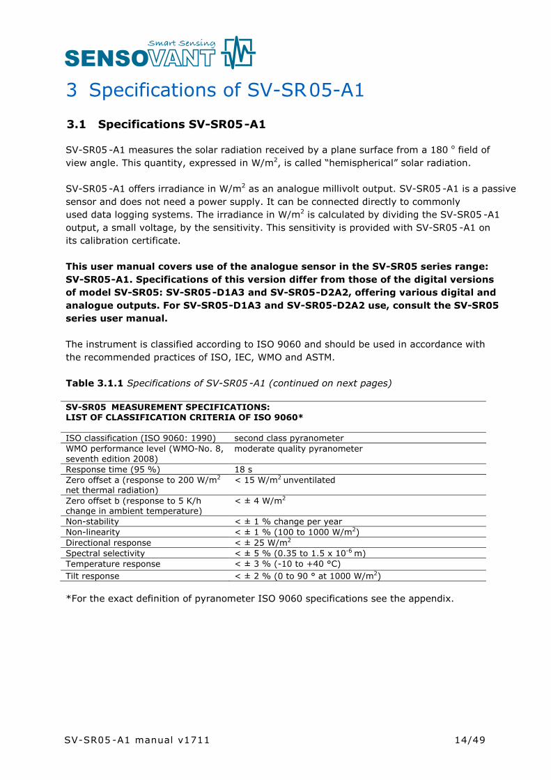
Table 3.1.1 Specifications of SV-SR05 -A1 (continued on next pages)
SV-SR05 MEASUREMENT SPECIFICATIONS:LIST OF CLASSIFICATION CRITERIA OF ISO 9060*
ISO classification (ISO 9060: 1990) second class pyranometer WMO performance level (WMO-No. 8, seventh edition 2008)
moderate quality pyranometer
Response time (95 %) 18 sZero offset a (response to 200 W/m2
net thermal radiation)< 15 W/m2 unventilated
Zero offset b (response to 5 K/h change in ambient temperature)
< ± 4 W/m2
Non-stability < ± 1 % change per yearNon-linearity < ± 1 % (100 to 1000 W/m2)Directional response < ± 25 W/m2
Spectral selectivity < ± 5 % (0.35 to 1.5 x 10⁻⁶ m)Temperature response < ± 3 % (-10 to +40 °C) Tilt response < ± 2 % (0 to 90 ° at 1000 W/m2)
*For the exact definition of pyranometer ISO 9060 specifications see the appendix.
SV-SR05 -A1 manual v1711
15/49
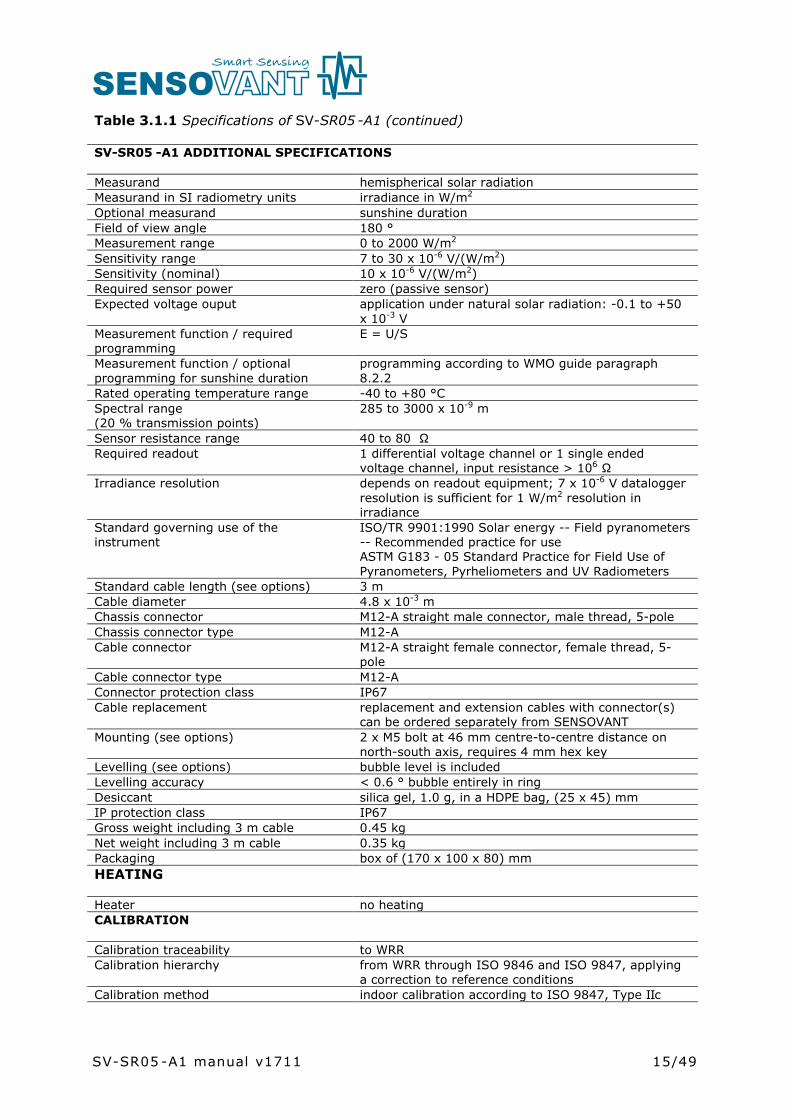
Table 3.1.1 Specifications of SV-SR05 -A1 (continued)
SV-SR05 -A1 ADDITIONAL SPECIFICATIONS
Measurand hemispherical solar radiationMeasurand in SI radiometry units irradiance in W/m2
Optional measurand sunshine durationField of view angle 180 °Measurement range 0 to 2000 W/m2
Sensitivity range 7 to 30 x 10-6 V/(W/m2)Sensitivity (nominal) 10 x 10-6 V/(W/m2)Required sensor power zero (passive sensor)Expected voltage ouput application under natural solar radiation: -0.1 to +50
x 10-3 VMeasurement function / required programming
E = U/S
Measurement function / optional programming for sunshine duration
programming according to WMO guide paragraph 8.2.2
Rated operating temperature range -40 to +80 °CSpectral range (20 % transmission points)
285 to 3000 x 10-9 m
Sensor resistance range 40 to 80 Ω Required readout 1 differential voltage channel or 1 single ended
voltage channel, input resistance > 106 ΩIrradiance resolution depends on readout equipment; 7 x 10⁻⁶ V datalogger
resolution is sufficient for 1 W/m2 resolution in irradiance
Standard governing use of the instrument
ISO/TR 9901:1990 Solar energy -- Field pyranometers -- Recommended practice for useASTM G183 - 05 Standard Practice for Field Use of Pyranometers, Pyrheliometers and UV Radiometers
Standard cable length (see options) 3 mCable diameter 4.8 x 10⁻³ mChassis connector M12-A straight male connector, male thread, 5-poleChassis connector type M12-ACable connector M12-A straight female connector, female thread, 5-
poleCable connector type M12-AConnector protection class IP67 Cable replacement replacement and extension cables with connector(s)
can be ordered separately from SENSOVANTMounting (see options) 2 x M5 bolt at 46 mm centre-to-centre distance on
north-south axis, requires 4 mm hex key Levelling (see options) bubble level is includedLevelling accuracy < 0.6 ° bubble entirely in ringDesiccant silica gel, 1.0 g, in a HDPE bag, (25 x 45) mmIP protection class IP67Gross weight including 3 m cable 0.45 kgNet weight including 3 m cable 0.35 kgPackaging box of (170 x 100 x 80) mmHEATING
Heater no heatingCALIBRATION
Calibration traceability to WRRCalibration hierarchy from WRR through ISO 9846 and ISO 9847, applying
a correction to reference conditionsCalibration method indoor calibration according to ISO 9847, Type IIc
SV-SR05 -A1 manual v1711
16/49
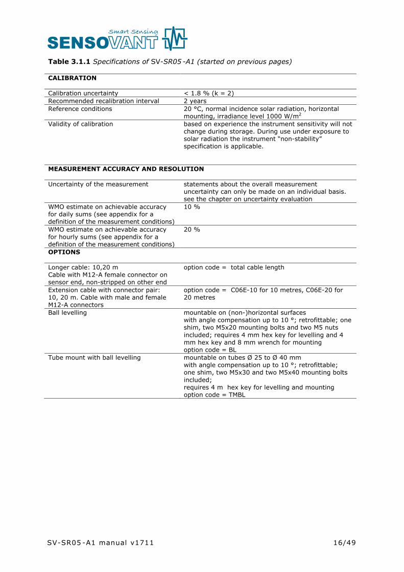
Table 3.1.1 Specifications of SV-SR05 -A1 (started on previous pages)
CALIBRATION
Calibration uncertainty < 1.8 % (k = 2)Recommended recalibration interval 2 yearsReference conditions 20 °C, normal incidence solar radiation, horizontal
mounting, irradiance level 1000 W/m2
Validity of calibration based on experience the instrument sensitivity will not change during storage. During use under exposure to solar radiation the instrument “non-stability” specification is applicable.
MEASUREMENT ACCURACY AND RESOLUTION
Uncertainty of the measurement statements about the overall measurement uncertainty can only be made on an individual basis. see the chapter on uncertainty evaluation
WMO estimate on achievable accuracy for daily sums (see appendix for a definition of the measurement conditions)
10 %
WMO estimate on achievable accuracy for hourly sums (see appendix for a definition of the measurement conditions)
20 %
OPTIONS
Longer cable: 10,20 mCable with M12-A female connector on sensor end, non-stripped on other end
option code = total cable length
Extension cable with connector pair: 10, 20 m. Cable with male and female M12-A connectors
option code = C06E-10 for 10 metres, C06E-20 for 20 metres
Ball levelling mountable on (non-)horizontal surfaces with angle compensation up to 10 °; retrofittable; one shim, two M5x20 mounting bolts and two M5 nuts included; requires 4 mm hex key for levelling and 4 mm hex key and 8 mm wrench for mountingoption code = BL
Tube mount with ball levelling mountable on tubes Ø 25 to Ø 40 mm with angle compensation up to 10 °; retrofittable;one shim, two M5x30 and two M5x40 mounting boltsincluded; requires 4 m hex key for levelling and mountingoption code = TMBL
SV-SR05 -A1 manual v1711

17/49
3.2 Dimensions of SR05-A1
Figure 3.2.1 Dimensions of SV-SR05 in x 10-3 m. The bottom drawing shows the height of SV-SR05 combined with its op tional ball levelling mount and the tube diameter required for use with SV-SR05’s optional tube mount. M5 mounting bolts and the countersunk set screw require a 4 mm hex key for mounting and levelling.
SV-SR05 -A1 manual v1711

18/49
4 Standards and recommended practices for use
Pyranometers are classified according to the ISO 9060 standard and the WMO-No. 8Guide. In any application the instrument should be used in accordance with the recommended practices of ISO, IEC, WMO and / or ASTM.
4.1 Classification standard
Table 4.1.1 Standards for pyranometer classification. See the appendix for definitions ofpyranometer specifications, and a table listing the specification limits.
STANDARDS FOR INSTRUMENT CLASSIFICATION
ISO STANDARD EQUIVALENTASTM STANDARD
WMO
ISO 9060:1990Solar energy -- specification and classification of instruments for measuring hemispherical solar and direct solar radiation
Not available WMO-No. 8; Guide to Meteorological Instruments and Methods of Observation, chapter 7, measurement of radiation, 7.3 measurement of global and diffuse solar radiation
4.2 General use for solar radiation measurement
Table 4.2.1 Standards with recommendations for instrument use in solar radiation measurement
STANDARDS FOR INSTRUMENT USE FOR HEMISPHERICAL SOLAR RADIATION
ISO STANDARD EQUIVALENTASTM STANDARD
WMO
ISO/TR 9901:1990 Solar energy -- Field pyranometers -- Recommended practice for use
ASTM G183 - 05Standard Practice for Field Use of Pyranometers, Pyrheliometers and UV Radiometers
WMO-No. 8; Guide to Meteorological Instruments and Methods of Observation, chapter 7, measurement of radiation, 7.3 measurement of global and diffuse solar radiation
4.3 General use for sunshine duration measurementAccording to the World Meteorological Organization (WMO, 2003), sunshine duration during a given period is defined as the sum of that sub-period for which the direct solar irradiance exceeds 120 W/m2.
SV-SR05 -A1 manual v1711
19/49
WMO has approved the “pyranometric method” to estimate sunshine duration from pyranometer measurements (Chapter 8 of the WMO Guide to Instruments and Observation, 2008). This implies that a pyranometer may be used, in combination with appropriate software, to estimate sunshine duration. Ask for our application note.
Table 4.3.1 Standards with recommendations for instrument use in sunshine duration measurement
STANDARDS FOR INSTRUMENT USE FOR SUNSHINE DURATION
WMO
WMO-No. 8; Guide to Meteorological Instruments and Methods of Observation, chapter 8, measurement of sunshine duration, 8.2.2 Pyranometric Method
4.4 Specific use for outdoor PV system performance testing
Pyranometers are used for monitoring PV power plant efficiency, in order to measureincoming solar radiation independently from the PV system. Pyranometers can be placedin two positions:
• plane of array (POA), parallel to the PV panels, for measurement of the in-planeirradiance (also noted as Gi in IEC 61724-1)
• horizontally, for measurement of the global horizontal irradiance (E, also noted as GHIin IEC 61724-1)
SV-SR 05-A1 is applicable in outdoor PV system performance testing. See also SENSOVANTmodel SR20 “secondary standard pyranometer”.
Table 4.4.1 Standards with recommendations for instrument use in PV system performance testing
STANDARDS ON PV SYSTEM PERFORMANCE TESTING
IEC / ISO STANDARD EQUIVALENT ASTM STANDARD
IEC 61724-1; Photovoltaic system performance monitoring – guidelines for measurement, data exchange and analysis
COMMENT: Allows pyranometers or reference cells according to IEC 60904-2 and -6. Pyranometer reading required accuracy better than 5% of reading (Par 4.1)
COMMENT: equals JISC 8906 (Japanese Industrial Standards Committee)
ASTM 2848-11; Standard Test Method for Reporting Photovoltaic Non-Concentrator System Performance
COMMENT: confirms that a pyranometer is the preferred instrument for outdoor PV testing. Specifically recommends a “first class” pyranometer (paragraph A 1.2.1.)
SV-SR05 -A1 manual v1711

20/49
4.5 Specific use in meteorology and climatology
The World Meteorological Organization (WMO) is a specialised agency of the United Nations. It is the UN system's authoritative voice on the state and behaviour of the earth's atmosphere and climate. WMO publishes WMO-No. 8; Guide to Meteorological Instruments and Methods of Observation, in which a table is included on “level of performance” of pyranometers. Nowadays WMO conforms itself to the ISO classification system.
SV-SR05 -A1 manual v1711

21/49
5 Installation of SV-SR05 -A1
5.1 Site selection and installation
Table 5.1.1 Recommendations for installation of pyranometers
Location the situation that shadows are cast on the instruments is usually not desirable. The horizon should be as free from obstacles as possible. Ideally there should be no objects between the course of the sun and the instrument.
Mechanical mounting / thermal insulation preferably use the ball levelling mount to mount SV-SR05 to a (non-)horizontal surface. A pyranometer is sensitive to thermal shocks. Do not mount the instrument on objects that become very hot (black coated metal plates).
Instrument mounting with 2 bolts 2 x M5 bolt at 46 mm centre-to-centre distance on north-south axis, connection through the sensor bottom in SR05’s standard configuration.
with ball levelling option: 2 x M5 bolt at 46 mm centre-to-centre distance, connection through ball levelling mount, M5x20 bolts and M5 nuts included.
with ball levelling on tube mount option: 2 x M5 boltat 46 mm centre-to-centre distance, connection through tube and ball levelling mount, M5x30 and M5x40 bolts included.
Performing a representative measurement
the pyranometer measures the solar radiation in the plane of the sensor. This may require installation in a tilted or inverted position. The black sensor surface (sensor bottom plate) should be mounted parallel to the plane of interest. In case a pyranometer is not mounted horizontally or in case the horizon is obstructed, the representativeness of the location becomes an important element of the measurement. See the chapter on uncertainty evaluation.
Levelling in case of horizontal mounting use the bubble level and optionally the ball levelling mount. The bubble level is visible and can be inspected at all times.
Instrument orientation by convention with the cable exit pointing to the nearest pole (so the cable exit should point north in the northern hemisphere, south in the southern hemisphere).
Installation height in case of inverted installation, WMO recommends a distance of 1.5 m between soil surface and sensor (reducing the effect of shadows and in order to obtain good spatial averaging).
SV-SR05 -A1 manual v1711

22/49
5.2 Mounting and levelling SV-SR05
SV-SR05 in its standard configuration is equipped with a visible bubble level and two mounting holes. For easy mounting and levelling on a (non-)horizontal surface, SV-SR05’s optional ball levelling is recommended. Ball levelling offers:• easy levelling• easy cable orientation• easy instrument exchange • easy mounting (mounting screws and nuts included)
When installing SV-SR05, ball levelling allows SV-SR05 to rotate 360 ° and to tilt up to 10 °.This allows compensation for up to a ten degree angle when installing on a non-horizontal surface. A 4 mm hex key (un)locks the ball levelling mechanism. When using a tube or rod for installing SV-SR05, the optional tube mount is recommended. Combined with ball levelling it allows mounting to a 25 to 40 mm diameter tube with the same ease of levelling and instrument exchange.
Figure 5.2.1 From left to right: SV-SR05 in its standard configuration with 3 metre cable; with optional ball levelling for easy mounting and levelling on a (non-)horizontal surface;with optional ball levelling and tube mount for easy installation on a 25 to 40 mm diameter tube. Mounting screws are included with the ball levelling and / or tube mount.
5.3 Installing SV-SR05
SV-SR05 without ball levelling and tube mounting options can be mounted using two M5 bolts (not included). For the required screw lengths, 5 to 7 mm should be added to the thickness of the user’s mounting platform. See the chapter on required tooling.
SR05 SR05-BL -SR05 TMBL
SV-SR05 -A1 manual v1711
23/49
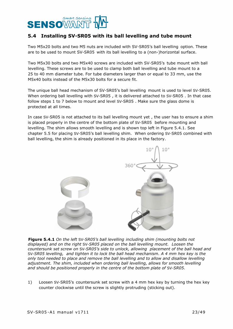
5.4 Installing SV-SR05 with its ball levelling and tube mount
Two M5x20 bolts and two M5 nuts are included with SV-SR05’s ball levelling option. Theseare to be used to mount SV-SR05 with its ball levelling to a (non-)horizontal surface.
Two M5x30 bolts and two M5x40 screws are included with SV-SR05’s tube mount with ball levelling. These screws are to be used to clamp both ball levelling and tube mount to a 25 to 40 mm diameter tube. For tube diameters larger than or equal to 33 mm, use the M5x40 bolts instead of the M5x30 bolts for a secure fit.
The unique ball head mechanism of SV-SR05’s ball levelling mount is used to level SV-SR05. When ordering ball levelling with SV-SR05 , it is delivered attached to SV-SR05 . In that casefollow steps 1 to 7 below to mount and level SV-SR05 . Make sure the glass dome is protected at all times.
In case SV-SR05 is not attached to its ball levelling mount yet , the user has to ensure a shim is placed properly in the centre of the bottom plate of SV-SR05 before mounting and levelling. The shim allows smooth levelling and is shown top left in Figure 5.4.1. See chapter 5.5 for placing SV-SR05’s ball levelling shim. When ordering SV-SR05 combined with ball levelling, the shim is already positioned in its place in the factory.
Figure 5.4.1 On the left SV-SR05’s ball levelling including shim (mounting bolts not displayed) and on the right SV-SR05 placed on the ball levelling mount. Loosen thecountersunk set screw on SV-SR05’s side to unlock, allowing placement of the ball head and SV-SR05 levelling, and tighten it to lock the ball head mechanism. A 4 mm hex key is the only tool needed to place and remove the ball levelling and to allow and disallow levelling adjustment. The shim, included when ordering ball levelling, allows for smooth levelling and should be positioned properly in the centre of the bottom plate of SV-SR05.
1) Loosen SV-SR05’s countersunk set screw with a 4 mm hex key by turning the hex key counter clockwise until the screw is slightly protruding (sticking out).
SV-SR05 -A1 manual v1711
24/49
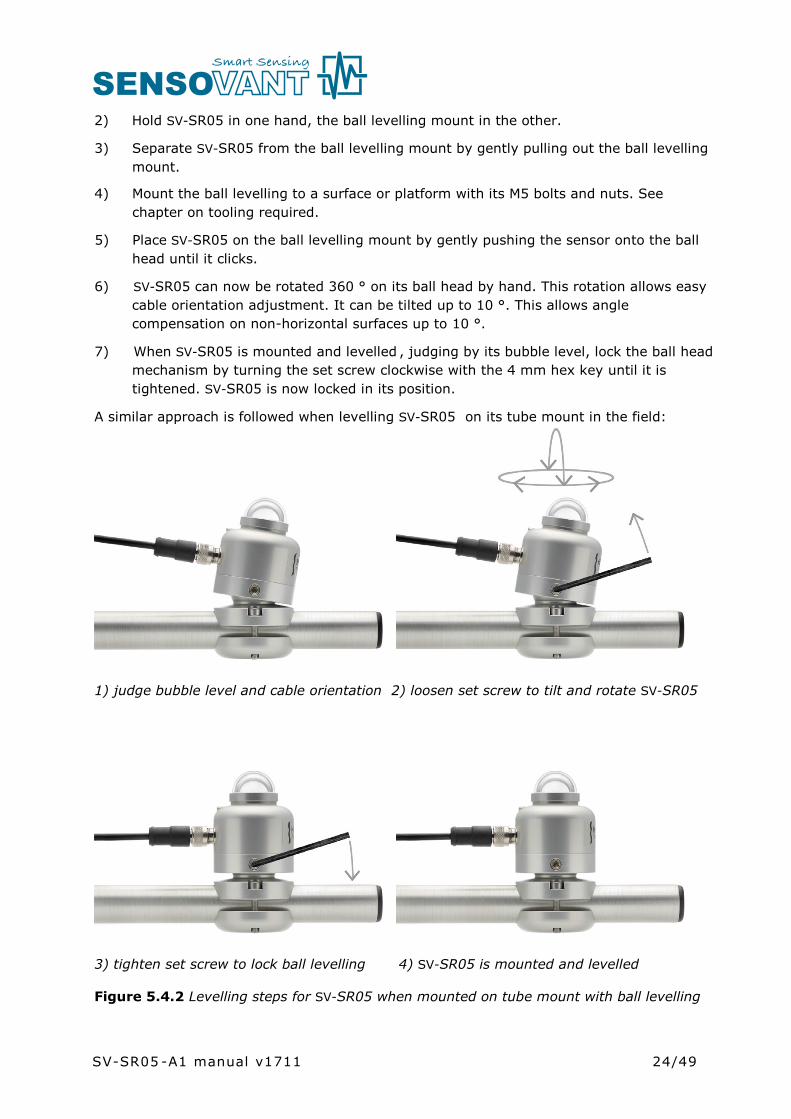
2) Hold SV-SR05 in one hand, the ball levelling mount in the other.
3) Separate SV-SR05 from the ball levelling mount by gently pulling out the ball levelling mount.
4) Mount the ball levelling to a surface or platform with its M5 bolts and nuts. Seechapter on tooling required.
5) Place SV-SR05 on the ball levelling mount by gently pushing the sensor onto the ball head until it clicks.
6) SV-SR05 can now be rotated 360 ° on its ball head by hand. This rotation allows easy cable orientation adjustment. It can be tilted up to 10 °. This allows angle compensation on non-horizontal surfaces up to 10 °.
7) When SV-SR05 is mounted and levelled , judging by its bubble level, lock the ball head mechanism by turning the set screw clockwise with the 4 mm hex key until it is tightened. SV-SR05 is now locked in its position.
A similar approach is followed when levelling SV-SR05 on its tube mount in the field:
1) judge bubble level and cable orientation 2) loosen set screw to tilt and rotate SV-SR05
3) tighten set screw to lock ball levelling 4) SV-SR05 is mounted and levelled
Figure 5.4.2 Levelling steps for SV-SR05 when mounted on tube mount with ball levelling
SV-SR05 -A1 manual v1711
25/49
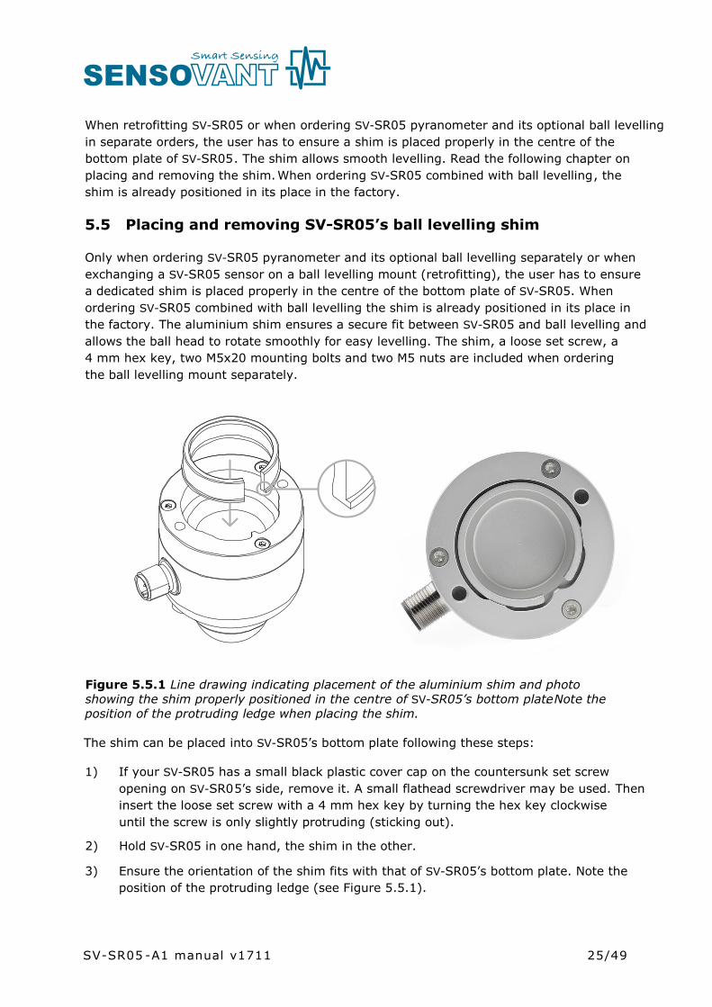
When retrofitting SV-SR05 or when ordering SV-SR05 pyranometer and its optional ball levelling in separate orders, the user has to ensure a shim is placed properly in the centre of the bottom plate of SV-SR05. The shim allows smooth levelling. Read the following chapter on placing and removing the shim.When ordering SV-SR05 combined with ball levelling, the shim is already positioned in its place in the factory.
5.5 Placing and removing SV-SR05’s ball levelling shim
Only when ordering SV-SR05 pyranometer and its optional ball levelling separately or when exchanging a SV-SR05 sensor on a ball levelling mount (retrofitting), the user has to ensure a dedicated shim is placed properly in the centre of the bottom plate of SV-SR05. When ordering SV-SR05 combined with ball levelling the shim is already positioned in its place in the factory. The aluminium shim ensures a secure fit between SV-SR05 and ball levelling and allows the ball head to rotate smoothly for easy levelling. The shim, a loose set screw, a 4 mm hex key, two M5x20 mounting bolts and two M5 nuts are included when ordering the ball levelling mount separately.
Figure 5.5.1 Line drawing indicating placement of the aluminium shim and photo showing the shim properly positioned in the centre of SV-SR05’s bottom plate. Note the position of the protruding ledge when placing the shim.
The shim can be placed into SV-SR05’s bottom plate following these steps:
1) If your SV-SR05 has a small black plastic cover cap on the countersunk set screw opening on SV-SR05’s side, remove it. A small flathead screwdriver may be used. Then insert the loose set screw with a 4 mm hex key by turning the hex key clockwise until the screw is only slightly protruding (sticking out).
2) Hold SV-SR05 in one hand, the shim in the other.
3) Ensure the orientation of the shim fits with that of SV-SR05’s bottom plate. Note the position of the protruding ledge (see Figure 5.5.1).
SV-SR05 -A1 manual v1711

26/49
4) Pinch the shim slightly in order to reduce its diameter and to make it fit easily into SV-SR05’s bottom plate.
5) While pinching, push the shim into its position on SV-SR05’s bottom plate.
The shim is placed. For mounting and levelling, continue with the following steps:
6) Mount the ball levelling with its mounting screws.
7) SV-SR05, with its shim positioned, can now be placed on the ball levelling mount. Gently push the sensor onto the ball head until it clicks.
8) The ball head can be rotated 360 ° and allows angle compensation on non-horizontal surfaces up to 10 °.
9) When SV-SR05 is mounted and levelled, judging by its bubble level, lock the ball head mechanism by turning the set screw clockwise with a 4 mm hex key until it is tightened. The set screw should be countersunk and not protruding (not sticking out).
When the ball head is not inserted in SV-SR05, the shim makes a minor rattling noise when moving SV-SR05. This is normal, caused by mechanical freedom between the two parts.
The shim can be removed from SV-SR05’s bottom plate by hand with the assistance of a small flathead screwdriver. See the chapter on tooling required. Let the screwdriver gently tip the shim out. When removing or placing the shim, make sure the glass dome is protected at all times.
SV-SR05 -A1 manual v1711
27/49
5.6 Electrical connection of SV-SR05-A1
This user manual covers use of the analogue sensor in the SV-SR05 series range: SV-SR05-A1. Specifications of this version differ from those of the digital versions of model SV-SR05: SV-SR05-D1A3 and SV-SR05-D2A2, offering various digital and analogue outputs. For SV-SR05-D1A3 and SV-SR05-D2A2 use, consult the SV-SR05 series user manual.
In order to operate, a pyranometer should be connected to a measurement system, typically a so-called datalogger. SV-SR05 -A1 is a passive sensor that does not need any power. Cables generally act as a source of distortion, by picking up capacitive noise. We recommend keeping the distance between a datalogger or amplifier and the sensor as short as possible. For cable extension, see the appendix on this subject.
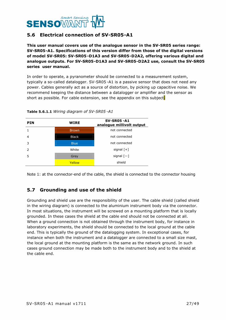
Table 5.6.1.1 Wiring diagram of SV-SR05 -A1
PIN WIRE SV-SR05 -A1analogue millivolt output
1 Brown not connected
4 Black not connected
3 Blue not connected
2 White signal [+]
5 Grey signal [—]
Yellow shield
Note 1: at the connector-end of the cable, the shield is connected to the connector housing
5.7 Grounding and use of the shield
Grounding and shield use are the responsibility of the user. The cable shield (called shieldin the wiring diagram) is connected to the aluminium instrument body via the connector. In most situations, the instrument will be screwed on a mounting platform that is locally grounded. In these cases the shield at the cable end should not be connected at all. When a ground connection is not obtained through the instrument body, for instance in laboratory experiments, the shield should be connected to the local ground at the cable end. This is typically the ground of the datalogging system. In exceptional cases, for instance when both the instrument and a datalogger are connected to a small size mast, the local ground at the mounting platform is the same as the network ground. In such cases ground connection may be made both to the instrument body and to the shield at the cable end.
SV-SR05 -A1 manual v1711

28/49
5.8 Using SV-SR05-A1’s analogue millivolt ouput
Using the analogue SV-SR05 -A1 is easy: the pyranometer can be connected directly to commonly used data logging systems. The irradiance in W/m2 is calculated by dividing the SV-SR05 -A1 output, a small voltage, by the sensitivity. This sensitivity is provided with SV-SR05 -A1 on its calibration certificate.
The central equation governing SV-SR05- A1 is: E = U/S (Formula 0.1)
5.8.1 Requirements for data acquisition / amplification
SV-SR05 -A1 is a passive sensor that does not need any power. In order to operate, a pyranometer should be connected to a measurement system, typically a so-called datalogger. The selection and programming of dataloggers is the responsibility of the user. Please contact the supplier of the data acquisition and amplification equipment to see if directions for use with the SV-SR05 -A1 are available. In case programming for similar instruments is available, this can typically also be used. SV-SR05 -A1 can usually be treated in the same way as other thermopile pyranometers. Pyranometers usually have the same programming as heat flux sensors.
When using SV-SR05 -A1 combined with read-out unit / datalogger LI19, please consult the LI19 manual as well.
Table 5.8.1.1 Requirements for data acquisition and amplification equipment for SV-SR05-A1 in its standard configuration
Capability to measure small voltage signals
preferably: 5 x 10⁻⁶ V uncertaintyMinimum requirement: 20 x 10-6 V uncertainty(valid for the entire expected temperature range of the acquisition / amplification equipment)
Capability for the data logger or the software
to store data, and to perform division by the sensitivity to calculate the solar irradiance. E = U/S (Formula 0.1)
Data acquisition input resistance > 1 x 10⁶ Ω
Open circuit detection(WARNING)
open-circuit detection should not be used, unless this is done separately from the normal measurement by more than 5 times the sensor response time and with a small current only. Thermopile sensors are sensitive to the current that is used during open circuit detection. The current will generate heat, which is measured and will appear as an offset.
SV-SR05 -A1 manual v1711

29/49
6 Making a dependable measurement
6.1 The concept of dependability
A measurement with a pyranometer is called “dependable” if it is reliable, i.e. measuring within required uncertainty limits, for most of the time and if problems, once they occur,can be solved quickly.
The requirements for a measurement with a pyranometer may be expressed by the user as:
• required uncertainty of the measurement (see following paragraphs)• requirements for maintenance and repairs (possibilities for maintenance and repair
including effort to be made and processing time)• a requirement to the expected instrument lifetime (until it is no longer feasible to
repair)
It is important to realise that the uncertainty of the measurement is not only determined by the instrument but also by the way it is used.
See also ISO 9060 note 5. In case of pyranometers, the measurement uncertainty as obtained during outdoor measurements is a function of:
• the instrument class • the calibration procedure / uncertainty• the duration of instrument employment under natural sunlight (involving the
instrument stability specification)• the measurement conditions (such as tilting, ventilation, shading, instrument
temperature)• maintenance (mainly fouling)• the environmental conditions*
Therefore, ISO 9060 says, “statements about the overall measurement uncertainty under outdoor conditions can only be made on an individual basis, taking all these factors into account”.
* defined at SENSOVANT as all factors outside the instrument that are relevant to the measurement such as the cloud cover (presence or absence of direct radiation), sun position, the local horizon (which may be obstructed) or condition of the ground (when tilted). The environmental conditions also involve the question whether or not the measurement at the location of measurement is representative of the quantity that should be measured.
SV-SR05 -A1 manual v1711

30/49
6.2 Reliability of the measurement
A measurement is reliable if it measures within required uncertainty limits for most of the time. We distinguish between two causes of unreliability of the measurement:
• related to the reliability of the pyranometer and its design, manufacturing, calibration (hardware reliability).
• related to the reliability of the measurement uncertainty (measurement reliability), which involves hardware reliability as well as condition of use.
Most of the hardware reliability is the responsibility of the instrument manufacturer.The reliability of the measurement however is a joint responsibility of instrument manufacturer and user. As a function of user requirements, taking into account measurement conditions and environmental conditions, the user will select an instrument of a certain class, and define maintenance support procedures.
In many situations there is a limit to a realistically attainable accuracy level. This is due to conditions that are beyond control once the measurement system is in place. Typical limiting conditions are:
• the measurement conditions, for instance when working at extreme temperatureswhen the instrument temperature is at the extreme limits of the rated temperature range.
• the environmental conditions, for instance when installed at a sub-optimal measurement location with obstacles in the path of the sun.
• other environmental conditions, for instance when assessing PV system performanceand the system contains panels at different tilt angles, the pyranometer measurement may not be representative of irradiance received by the entire PV system.
The measurement reliability can be improved by maintenance support. Important aspects are:
• dome fouling by deposition of dust, dew, rain or snow. Fouling results in undefined measurement uncertainty (sensitivity and directional error are no longer defined). This should be solved by regular inspection and cleaning.
• sensor instability. Maximum expected sensor aging is specified per instrument as its non-stability in [% change / year]. In case the sensor is not recalibrated, the uncertainty of the sensitivity gradually will increase. This is solved by regular recalibration.
• moisture condensing under pyranometer domes resulting in a slow change of sensitivity (within specifications). This is solved by regular replacement of desiccant or by maintenance (drying the entire sensor) in case the sensor allows this. For non-serviceable sensors like most second class pyranometers, this may slowly develop into a defect. For first class and secondary standard models (for instance model SR11first class pyranometer and SR20-D2 digital secondary standard pyranometer) extra desiccant (in a set of 5 bags in an air tight bag) is available.
SV-SR05 -A1 manual v1711

31/49
Another way to improve measurement reliability is to introduce redundant sensors.
• the use of redundant instruments allows remote checks of one instrument using the other as a reference, which leads to a higher measurement reliability.
• in PV system performance monitoring, in addition to instruments measuring in the plane of array, horizontally placed instruments are used for the measurement of global radiation. Global irradiance data enable the user to compare the local climate and system efficiency between different sites. These data can also be compared to measurements by local meteorological stations.
6.3 Speed of repair and maintenance
Dependability is not only a matter of reliability but also involves the reaction to problems; if the processing time of service and repairs is short, this contributes to the dependability.
SENSOVANT pyranometers are designed to allow easy maintenance and repair. The main maintenance actions are:
• replacement of desiccant• replacement of cabling
For optimisation of dependability a user should:
• estimate the expected lifetime of the instrument• design a schedule of regular maintenance• design a schedule of repair or replacement in case of defects
When operating multiple instruments in a network SENSOVANT recommends keeping procedures simple and having a few spare instruments to act as replacements during service, recalibrations and repair.
6.4 Uncertainty evaluation
The uncertainty of a measurement under outdoor or indoor conditions depends on many factors, see paragraph 1 of this chapter. It is not possible to give one figure for pyranometer measurement uncertainty. The work on uncertainty evaluation is “in progress”. There are several groups around the world participating in standardisation of the method of calculation. The effort aims to work according to the guidelines for uncertainty evaluation (according to the “Guide to Expression of Uncertainty in Measurement” or GUM).
SV-SR05 -A1 manual v1711

32/49
6.4.1 Evaluation of measurement uncertainty under outdoor conditions
SENSOVANT actively participates in the discussions about pyranometer measurement uncertainty; we also provide spreadsheets, reflecting the latest state of the art, to assist our users in making their own evaluation. The input to the assessment is summarised:
1) The formal evaluation of uncertainty should be performed in accordance with ISO 98-3 Guide to the Expression of Uncertainty in Measurement, GUM. 2) The specifications of the instrument according to the list of ISO 9060 classification of pyranometers and pyrheliometers are entered as limiting values of possible errors, to be analysed as type B evaluation of standard uncertainty per paragraph 4.3.7. of GUM. A priori distributions are chosen as rectangular.3) A separate estimate has to be entered to allow for estimated uncertainty due to the instrument maintenance level.4) The calibration uncertainty has to be entered. Please note that SENSOVANT calibration uncertainties are lower than those of alternative equipment. These uncertainties are entered in measurement equation (equation is usually Formula 0.1: E = U/S), either as an uncertainty in E (zero offsets, directional response) in U (voltage readout errors) or in S (tilt error, temperature dependence, calibration uncertainty).5) In uncertainty analysis for pyranometers, the location and date of interest is entered. The course of the sun is then calculated, and the direct and diffuse components are estimated, based on a model; the angle of incidence of direct radiation is a major factor in the uncertainty.6) In uncertainty analysis for modern pyrheliometers: tilt dependence often is so low that one single typical observation may be sufficient. 7) In case of special measurement conditions, typical specification values are chosen. These should for instance account for the measurement conditions (shaded / unshaded, ventilated/ unventilated, horizontal / tilted) and environmental conditions (clear sky / cloudy, working temperature range).8) Among the various sources of uncertainty, some are “correlated”; i.e. present during the entire measurement process, and not cancelling or converging to zero when averaged over time; the off-diagonal elements of the covariance matrix are not zero. Paragraph 5.2 of GUM.9) Among the various sources of uncertainty, some are “uncorrelated”; cancelling or converging to zero when averaged over time; the off-diagonal elements of the covariance matrix are zero. Paragraph 5.1 of GUM.10) Among the various sources of uncertainty, some are “not included in analysis”; this applies for instance to non-linearity for pyranometers, because it is already included in the directional error, and the spectral response for pyranometers and pyrheliometers because it is already taken into account in the calibration process.
SV-SR05 -A1 manual v1711

33/49
Table 6.4.1.1 Preliminary estimates of achievable uncertainties of measurements with SENSOVANT pyranometers. The estimates are based on typical pyranometer properties and calibration uncertainty, for sunny, clear sky days and well maintained stations, without uncertainty loss due to lack of maintenance and due to instrument fouling. The table specifies expanded uncertainties with a coverage factor of 2 and confidence level of 95 %. Estimates are based on 1 s sampling. IMPORTANT NOTE: there is no international consensus on uncertainty evaluation of pyranometer measurements, so this table should not be used as a formal reference.
Pyranometer class (ISO 9060)
season latitude uncertainty minute totals at solar noon
uncertainty hourly totals at solar noon
uncertainty daily totals
secondary standard
summer mid-latitude 2.7 % 2.0 % 1.9 %
equator 2.6 % 1.9 % 1.7 %pole 7.9 % 5.6 % 4.5 %
winter mid-latitude 3.4 % 2.5 % 2.7 %
first class summer mid-latitude 4.7 % 3.3 % 3.4 %
equator 4.4 % 3.1 % 2.9 %
pole 16.1% 11.4 % 9.2 %
winter mid-latitude 6.5 % 4.5 % 5.2 %
second class summer mid-latitude 8.4 % 5.9 % 6.2 %
series) equator 7.8 % 5.5 % 5.3 %
pole 29.5 % 21.6 % 18.0 %
winter mid-latitude 11.4 % 8.1 % 9.9 %
6.4.2 Calibration uncertainty
New calibration procedures were developed in close cooperation with PMOD World Radiation Center in Davos, Switzerland. The latest calibration method results in an uncertainty of the sensitivity of less than 1.8 %, compared to typical uncertainties of higher than 3.5 % for this pyranometer class. See the appendix for detailed information on calibration hierarchy.
SV-SR05 -A1 manual v1711
(SV-SR05
34/49
7 Maintenance and trouble shooting
7.1 Recommended maintenance and quality assurance
SV-SR05 -A1 can measure reliably at a low level of maintenance in most locations. Usually unreliable measurements will be detected as unreasonably large or small measured values. As a general rule this means that regular visual inspection combined with a critical review of the measured data, preferably checking against other measurements, is the preferred way to obtain a reliable measurement.
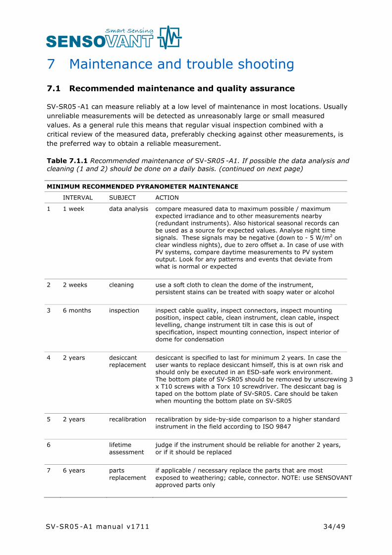
Table 7.1.1 Recommended maintenance of SV-SR05 -A1. If possible the data analysis and cleaning (1 and 2) should be done on a daily basis. (continued on next page)
MINIMUM RECOMMENDED PYRANOMETER MAINTENANCE
INTERVAL SUBJECT ACTION
1 1 week data analysis compare measured data to maximum possible / maximum expected irradiance and to other measurements nearby (redundant instruments). Also historical seasonal records can be used as a source for expected values. Analyse night time signals. These signals may be negative (down to - 5 W/m2 on clear windless nights), due to zero offset a. In case of use with PV systems, compare daytime measurements to PV system output. Look for any patterns and events that deviate from what is normal or expected
2 2 weeks cleaning use a soft cloth to clean the dome of the instrument, persistent stains can be treated with soapy water or alcohol
3 6 months inspection inspect cable quality, inspect connectors, inspect mounting position, inspect cable, clean instrument, clean cable, inspect levelling, change instrument tilt in case this is out of specification, inspect mounting connection, inspect interior of dome for condensation
4 2 years desiccant replacement
desiccant is specified to last for minimum 2 years. In case the user wants to replace desiccant himself, this is at own risk and should only be executed in an ESD-safe work environment. The bottom plate of SV-SR05 should be removed by unscrewing 3x T10 screws with a Torx 10 screwdriver. The desiccant bag is taped on the bottom plate of SV-SR05. Care should be taken when mounting the bottom plate on SV-SR05
5 2 years recalibration recalibration by side-by-side comparison to a higher standard instrument in the field according to ISO 9847
6 lifetime assessment
judge if the instrument should be reliable for another 2 years, or if it should be replaced
7 6 years parts replacement
if applicable / necessary replace the parts that are most exposed to weathering; cable, connector. NOTE: use SENSOVANT approved parts only
SV-SR05 -A1 manual v1711
35/49
7.2 Trouble shooting
7.2.1 Trouble shooting SV-SR05-A1
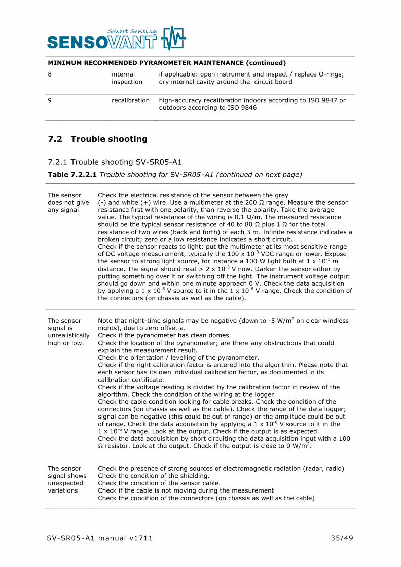
Table 7.2.2.1 Trouble shooting for SV-SR05 -A1 (continued on next page)
The sensor does not give any signal
Check the electrical resistance of the sensor between the grey(-) and white (+) wire. Use a multimeter at the 200 Ω range. Measure the sensor resistance first with one polarity, than reverse the polarity. Take the average value. The typical resistance of the wiring is 0.1 Ω/m. The measured resistance should be the typical sensor resistance of 40 to 80 Ω plus 1 Ω for the total resistance of two wires (back and forth) of each 3 m. Infinite resistance indicates a broken circuit; zero or a low resistance indicates a short circuit.Check if the sensor reacts to light: put the multimeter at its most sensitive range of DC voltage measurement, typically the 100 x 10-3 VDC range or lower. Expose the sensor to strong light source, for instance a 100 W light bulb at 1 x 10⁻¹ m distance. The signal should read > 2 x 10⁻³ V now. Darken the sensor either by putting something over it or switching off the light. The instrument voltage output should go down and within one minute approach 0 V. Check the data acquisition by applying a 1 x 10⁻⁶ V source to it in the 1 x 10⁻⁶ V range. Check the condition of the connectors (on chassis as well as the cable).
The sensor signal is unrealisticallyhigh or low.
Note that night-time signals may be negative (down to -5 W/m2 on clear windless nights), due to zero offset a.Check if the pyranometer has clean domes.Check the location of the pyranometer; are there any obstructions that could explain the measurement result.Check the orientation / levelling of the pyranometer.Check if the right calibration factor is entered into the algorithm. Please note that each sensor has its own individual calibration factor, as documented in its calibration certificate.Check if the voltage reading is divided by the calibration factor in review of the algorithm. Check the condition of the wiring at the logger.Check the cable condition looking for cable breaks. Check the condition of the connectors (on chassis as well as the cable). Check the range of the data logger; signal can be negative (this could be out of range) or the amplitude could be out of range. Check the data acquisition by applying a 1 x 10⁻⁶ V source to it in the1 x 10-6 V range. Look at the output. Check if the output is as expected.Check the data acquisition by short circuiting the data acquisition input with a 100 Ω resistor. Look at the output. Check if the output is close to 0 W/m2.
The sensor signal shows unexpected variations
Check the presence of strong sources of electromagnetic radiation (radar, radio)Check the condition of the shielding.Check the condition of the sensor cable.Check if the cable is not moving during the measurementCheck the condition of the connectors (on chassis as well as the cable)
MINIMUM RECOMMENDED PYRANOMETER MAINTENANCE (continued)
8 internal inspection
if applicable: open instrument and inspect / replace O-rings; dry internal cavity around the circuit board
9 recalibration high-accuracy recalibration indoors according to ISO 9847 or outdoors according to ISO 9846
SV-SR05 -A1 manual v1711

36/49
The dome shows internal condensation
Arrange to send the sensor back to SENSOVANT for diagnosis.
7.3 Calibration and checks in the field
Recalibration of field pyranometers is typically done by comparison in the field to a reference pyranometer. The applicable standard is ISO 9847 “International Standard-Solar Energy- calibration of field pyranometers by comparison to a reference pyranometer”. At SENSOVANT an indoor calibration according to the same standard is used.
SENSOVANT recommendation for re-calibration: if possible, perform calibration indoor by comparison to an identical reference instrument, under normal incidence conditions. The recommended calibration interval of pyranometers is 2 years.
In case of field comparison; ISO recommends field calibration to a higher class pyranometer. SENSOVANT suggests also allowing use of sensors of the same model and class, because intercomparisons of similar instruments have the advantage that they suffer from the same offsets. It is therefore just as good to compare to pyranometers of the same brand and type as to compare to an instrument of a higher class. ISO recommends to perform field calibration during several days; 2 to 3 days under cloudless conditions, 10 days under cloudy conditions. In general this is not achievable. In order to shorten the calibration process SENSOVANT suggests to allow calibration at normal incidence, using hourly totals near solar noon.
SENSOVANT main recommendations for field intercomparisons are:
1) to take normal incidence as a reference and not the entire day. 2) to take a reference of the same brand and type as the field pyranometer or a pyranometer of a higher class, and 3) to connect both to the same electronics, so that electronics errors (also offsets) are eliminated.4) to mount all instruments on the same platform, so that they have the same body temperature.5) assuming that the electronics are independently calibrated, to analyse radiation values at normal incidence radiation (possibly tilting the radiometers to approximately normal incidence), if this is not possible to compare 1 hour totals around solar noon for horizontally mounted instruments.6) for second class radiometers, to correct deviations of more than ± 10 %. Lower deviations should be interpreted as acceptable and should not lead to a revised sensitivity.7) for first class pyranometers, to correct deviations of more than ± 5 %. Lower deviations should be interpreted as acceptable and should not lead to a revised sensitivity.
SV-SR05 -A1 manual v1711

37/49
8) for secondary standard instruments, to correct deviations of more than ± 3 %. Lower deviations should be interpreted as acceptable and should not lead to a revised sensitivity.
7.4 Data quality assurance
Quality assurance can be done by:
• analysing trends in solar irradiance signal• plotting the measured irradiance against mathematically generated expected values• comparing irradiance measurements between sites• analysis of night time signals
The main idea is that one should look out for any unrealistic values. There are programs on the market that can semi-automatically perform data screening. See for more information on such a program: www.dqms.com.
SV-SR05 -A1 manual v1711

38/49SV-SR05 -A1 manual v1711

39/49
8 Appendices
8.1 Appendix on cable extension / replacement
The sensor cable of SV-SR05 -A1 is equipped with a M12-A straight connector. In case of cable replacement, it is recommended to purchase a new cable with connector at SENSOVANT. In case of cable extension, it is recommended to purchase an extension cable with connector pairs at SENSOVANT. Please note that SENSOVANT does not provide support for Do-It-Yourself connector- and cable assembly.
SV-SR05 -A1 is equipped with one cable. Keep the distance between data logger or amplifier and sensor as short as possible. Cables act as a source of distortion by picking up capacitive noise. In an electrically “quiet” environment the SV-SR05 -A1 cable can however be extended without problem to 100 metres. If done properly, the sensor signal, although small, will not significantly degrade because the sensor resistance is very low (so good immunity to external sources) and because there is no current flowing (so no resistive losses).
Connector and cable specifications are summarised on the next page.
Figure 8.1.1 On the left the SV-SR05 -A1 cable with M12-A female connector on sensor end. The cable is non-stripped on the other end. Its length is 3 metres standard and available in 10 and 20 metres too. On the right SENSOVANT extension cable with connector pairs, with male and female M12-A connectors, available in 10 and 20 metres.
SV-SR05 -A1 manual v1711

40/49
Table 8.1.1 Specifications for SV-SR05 -A1 cable replacement and extension
General replacement please order a new cable with connector at SENSOVANT
General cable extension please order an extension cable with connector pairs at SENSOVANT
Connectors used chassis: M12-A straight male connector, male thread, 5-polemanufacturer: Bindercable: M12-A straight female connector, female thread, 5-polemanufacturer: BinderThe shield is electrically connected to the connector
Cable 5-wire, shieldedmanufacturer: Binder
Length cables should be kept as short as possible
Outer sheath with specifications for outdoor use(for good stability in outdoor applications)
SV-SR05 -A1 manual v1711

41/49
8.2 Appendix on tools for SV-SR05 -A1
Table 8.2.1 Specifications of tools for SV-SR05 -A1
CONFIGURATION TOOLS INCLUDED
tooling required for mounting SV-SR05 without ball levelling
two M5 boltsapplicable screwdriver
nono
tooling required for mounting SV-SR05 with ball levelling
hex key 4 mm wrench size 8 mm for M5 nuts
yesno
tooling required for mounting SV-SR05 with tube mount
hex key 4 mm yes
tooling required for levelling SV-SR05with ball levelling and tube mount
hex key 4 mm yes
tooling required for tipping the aluminiumshim out of SV-SR05’s bottom panel position
screwdriver blade width 2 to 4 mm
no
8.3 Appendix on spare parts for SV-SR05 -A1
• SV-SR05-A1 cable with female M12-A connector on sensor end, non-stripped on other end (3, 10, 20 m). Specify cable length
• SV-SR05 -A1 extension cable with connector pair, with male and female M12-Aconnectors, (10, 20 m). Specify extension cable length
• Ball levelling (order number BL01)• Tube mount (order number TM01)• Tube mount with ball levelling (order number TMBL01)• Shim for ball levelling mount• Countersunk set screw for ball levelling mount• 2 x M5x40 mounting bolt• 2 x M5x30 mounting bolt• 2 x M5x20 mounting bolt with 2 x M5 nut• Desiccant (silica gel, 1.0 g, in a HDPE bag)
NOTE: Dome, level and sensor of SV-SR05 cannot be supplied as spare parts
SV-SR05 -A1 manual v1711

42/49
8.4 Appendix on standards for classification and calibration
Both ISO and ASTM have standards on instrument classification and methods of calibration. The World Meteorological Organisation (WMO) has largely adopted the ISO classification system.
Table 8.4.1 Pyranometer standardisation in ISO and ASTM.
STANDARDS ON INSTRUMENT CLASSIFICATION AND CALIBRATION
ISO STANDARD EQUIVALENT ASTM STANDARD
ISO 9060:1990 Solar energy -- Specification and classification of instruments for measuring hemispherical solar and direct solar radiation
not availableComment: work is in progress on a new ASTM equivalent standard
Comment: a standard “Solar energy --Methods for testing pyranometer and pyrheliometer characteristics” has been announced in ISO 9060 but is not yet implemented.
not available
ISO 9846:1993 Solar energy -- Calibration of a pyranometer using a pyrheliometer
ASTM G167-05 Standard Test Method for Calibration of a Pyranometer Using a Pyrheliometer
ISO 9847:1992 Solar energy -- Calibration of field pyranometers by comparison to a reference pyranometer
ASTM E 824-10 Standard Test Method for Transfer of Calibration from Reference to Field Radiometers
ASTM G207-11 Standard Test Method for Indoor Transfer of Calibration from Reference to Field Pyranometers
ISO 9059:1990 Solar energy -- Calibration of field pyrheliometers by comparison to a reference pyrheliometer
ASTM E 816 Standard Test Method for Calibration of Pyrheliometers by Comparison to Reference Pyrheliometers
not available ASTM G213-17 Standard Guide for Evaluating Uncertainty in Calibration and Field Measurements of Broadband Irradiance with Pyranometers and Pyrheliometers
SV-SR05 -A1 manual v1711

43/49
8.5 Appendix on calibration hierarchy
The World Radiometric Reference (WRR) is the measurement standard representing the Sl unit of irradiance. Use of WRR is mandatory when working according to the standards of both WMO and ISO. ISO9874 states under paragraph 1.3: the methods of calibration specified are traceable to the WRR. The WMO manual states under paragraph 7.1.2.2: the WRR is accepted as representing the physical units of total irradiance.
The worldwide homogeneity of the meteorological radiation measurements is guaranteed by the World Radiation Center in Davos Switzerland, by maintaining the World Standard Group (WSG) which materialises the World Radiometric Reference.
See www.pmodwrc.ch
The SENSOVANT standard is traceable to an outdoor WRR calibration. Some small corrections are made to transfer this calibration to the SENSOVANT standard conditions: sun at zenith and 1000 W/m2 irradiance level. During the outdoor calibration the sun is typically at 20 to 40° zenith angle, and the total irradiance at a 700 W/m2 level.
Table 8.5.1 Calibration hierarchy for pyranometers
WORKING STANDARD CALIBRATION AT PMOD / WRC DAVOS
Calibration of working standard pyranometers:Method: ISO 9846, type 1 outdoor. This working standard has an uncertainty “uncertainty of standard”. The working standard has been calibrated under certain “test conditions of the standard”. The working standard has traceability to WRR world radiometric reference.
CORRECTION OF (WORKING) STANDARD CALIBRATION TO STANDARDISED REFERENCE CONDITIONS
Correction from “test conditions of the standard” to “reference conditions” i.e. to normal incidence and 20 °C:Using known (working) standard pyranometer properties: directional, non linearity, offsets, temperature dependence). This correction has an uncertainty; “uncertainty of correction”.At SENSOVANT we also call the working standard pyranometer “standard”.
INDOOR PRODUCT CALIBRATION
Calibration of products, i.e. pyranometers: Method: according to ISO 9847, Type IIc, which is an indoor calibration.This calibration has an uncertainty associated with the method.(In some cases like the BSRN network the product calibration is with a different method; for example again type 1 outdoor)
CALIBRATION UNCERTAINTY CALCULATION
ISO 98-3 Guide to the Expression of Uncertainty in Measurement, GUM Determination of combined expanded uncertainty of calibration of the product, including uncertainty of the working standard, uncertainty of correction, uncertainty of the method (transfer error). The coverage factor must be determined; at SENSOVANT we work with a coverage factor k = 2.
SV-SR05 -A1 manual v1711

44/49
8.6 Appendix on meteorological radiation quantities
A pyranometer measures irradiance. The time integrated total is called radiant exposure. In solar energy radiant exposure is often given in W∙h/m2.
Table 8.6.1 Meteorological radiation quantities as recommended by WMO (additional symbols by SENSOVANT Thermal Sensor).POA stands for Plane of Array irradiance. The term originates from ASTM and IEC standards.
SYMBOL DESCRIPTION CALCULATION UNITS ALTERNATIVE EXPRESSION
E downward irradiance E = Eg + El W/m2
H downward radiant exposure for a specified time interval
H = Hg + Hl J/m2
E upward irradiance E = Eg + El W/m2
H upward radiant exposure for a specified time interval
H = Hg + Hl J/m2 W∙h/m2 Change of units
E direct solar irradiance normal to the apparent solar zenith angle
W/m2 DNI Direct Normal Irradiance
E0 solar constant W/m2
Eg h global irradiance; hemispherical irradiance on a specified, in this case horizontal surface.*
Eg = E cos θh + Ed W/m2 GHI Global Horizontal Irradiance
Eg t global irradiance; hemispherical irradiance on a specified, in this case tilted surface.*
Eg = E∙cos θt + Ed t + Er t ***
W/m2 POA Plane of Array
Ed downward diffuse solar radiation
W/m2 DHI Diffuse Horizontal Irradiance
El , El upward / downward long-wave irradiance
W/m2
Er reflected solar irradiance W/m2
E* net irradiance E* = E – E W/m2
T apparent surface temperature**
ºC or K
T apparent sky temperature**
ºC or K
SD sunshine duration h
θ is the apparent solar zenith angle θh relative to horizontal, θt relative to a tilted surface g = global, l = long wave, t = tilted *, h = horizontal** distinction horizontal and tilted from SENSOVANT** T symbols introduced by SENSOVANT*** contributions of Ed t and Er t are Ed and Er both corrected for the tilt angle of the surface
SV-SR05 -A1 manual v1711
45/49
8.7 Appendix on ISO and WMO classification tables
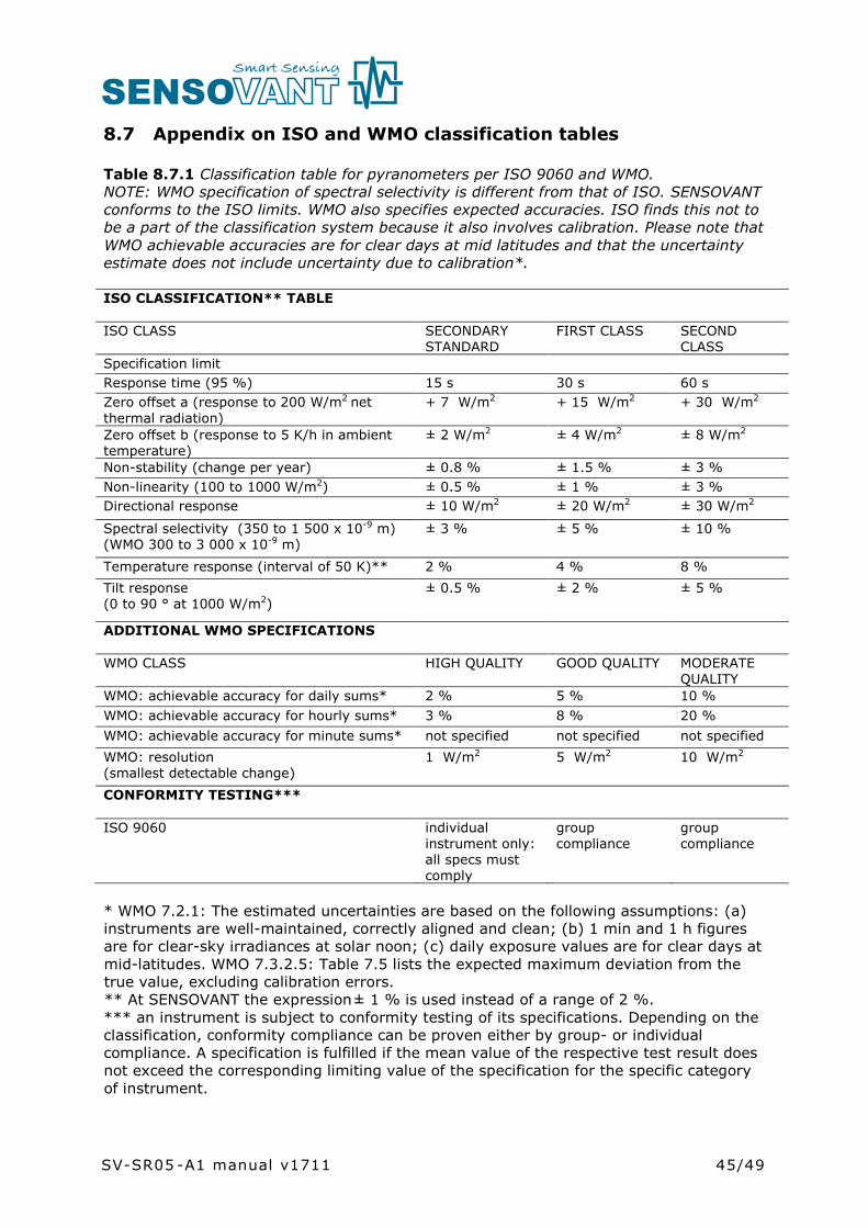
Table 8.7.1 Classification table for pyranometers per ISO 9060 and WMO. NOTE: WMO specification of spectral selectivity is different from that of ISO. SENSOVANTconforms to the ISO limits. WMO also specifies expected accuracies. ISO finds this not to be a part of the classification system because it also involves calibration. Please note that WMO achievable accuracies are for clear days at mid latitudes and that the uncertainty estimate does not include uncertainty due to calibration*.
ISO CLASSIFICATION** TABLE
ISO CLASS SECONDARY STANDARD
FIRST CLASS SECOND CLASS
Specification limitResponse time (95 %) 15 s 30 s 60 sZero offset a (response to 200 W/m2 net thermal radiation)
+ 7 W/m2 + 15 W/m2 + 30 W/m2
Zero offset b (response to 5 K/h in ambient temperature)
± 2 W/m2 ± 4 W/m2 ± 8 W/m2
Non-stability (change per year) ± 0.8 % ± 1.5 % ± 3 %Non-linearity (100 to 1000 W/m2) ± 0.5 % ± 1 % ± 3 %Directional response ± 10 W/m2 ± 20 W/m2 ± 30 W/m2
Spectral selectivity (350 to 1 500 x 10-9 m) (WMO 300 to 3 000 x 10-9 m)
± 3 % ± 5 % ± 10 %
Temperature response (interval of 50 K)** 2 % 4 % 8 %Tilt response (0 to 90 ° at 1000 W/m2)
± 0.5 % ± 2 % ± 5 %
ADDITIONAL WMO SPECIFICATIONS
WMO CLASS HIGH QUALITY GOOD QUALITY MODERATE QUALITY
WMO: achievable accuracy for daily sums* 2 % 5 % 10 %WMO: achievable accuracy for hourly sums* 3 % 8 % 20 %WMO: achievable accuracy for minute sums* not specified not specified not specifiedWMO: resolution (smallest detectable change)
1 W/m2 5 W/m2 10 W/m2
CONFORMITY TESTING***
ISO 9060 individual instrument only: all specs must comply
group compliance
group compliance
* WMO 7.2.1: The estimated uncertainties are based on the following assumptions: (a) instruments are well-maintained, correctly aligned and clean; (b) 1 min and 1 h figures are for clear-sky irradiances at solar noon; (c) daily exposure values are for clear days at mid-latitudes. WMO 7.3.2.5: Table 7.5 lists the expected maximum deviation from the true value, excluding calibration errors.** At SENSOVANT the expression ± 1 % is used instead of a range of 2 %.*** an instrument is subject to conformity testing of its specifications. Depending on the classification, conformity compliance can be proven either by group- or individual compliance. A specification is fulfilled if the mean value of the respective test result does not exceed the corresponding limiting value of the specification for the specific category of instrument.
SV-SR05 -A1 manual v1711
46/49
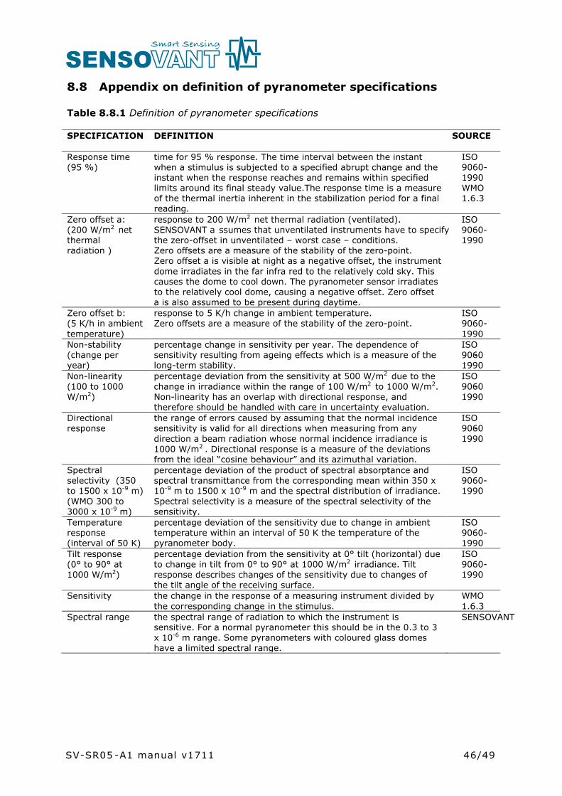
8.8 Appendix on definition of pyranometer specifications
Table 8.8.1 Definition of pyranometer specifications
SPECIFICATION DEFINITION SOURCE
Response time (95 %)
time for 95 % response. The time interval between the instant when a stimulus is subjected to a specified abrupt change and the instant when the response reaches and remains within specified limits around its final steady value.The response time is a measure of the thermal inertia inherent in the stabilization period for a final reading.
ISO 9060-1990WMO 1.6.3
Zero offset a:(200 W/m2 net thermalradiation )
response to 200 W/m2 net thermal radiation (ventilated). SENSOVANT a ssumes that unventilated instruments have to specify the zero-offset in unventilated – worst case – conditions.Zero offsets are a measure of the stability of the zero-point.Zero offset a is visible at night as a negative offset, the instrument dome irradiates in the far infra red to the relatively cold sky. Thiscauses the dome to cool down. The pyranometer sensor irradiates to the relatively cool dome, causing a negative offset. Zero offset a is also assumed to be present during daytime.
ISO 9060-1990
Zero offset b:(5 K/h in ambient temperature)
response to 5 K/h change in ambient temperature.Zero offsets are a measure of the stability of the zero-point.
ISO 9060-1990
Non-stability (change per year)
percentage change in sensitivity per year. The dependence ofsensitivity resulting from ageing effects which is a measure of the long-term stability.
ISO 9060-1990
Non-linearity (100 to 1000 W/m2)
percentage deviation from the sensitivity at 500 W/m2 due to the change in irradiance within the range of 100 W/m2 to 1000 W/m2.Non-linearity has an overlap with directional response, and therefore should be handled with care in uncertainty evaluation.
ISO 9060-1990
Directional response
the range of errors caused by assuming that the normal incidence sensitivity is valid for all directions when measuring from any direction a beam radiation whose normal incidence irradiance is 1000 W/m2 . Directional response is a measure of the deviations from the ideal “cosine behaviour” and its azimuthal variation.
ISO 9060-1990
Spectral selectivity (350 to 1500 x 10-9 m) (WMO 300 to 3000 x 10-9 m)
percentage deviation of the product of spectral absorptance and spectral transmittance from the corresponding mean within 350 x10-9 m to 1500 x 10-9 m and the spectral distribution of irradiance. Spectral selectivity is a measure of the spectral selectivity of the sensitivity.
ISO 9060-1990
Temperature response(interval of 50 K)
percentage deviation of the sensitivity due to change in ambient temperature within an interval of 50 K the temperature of the pyranometer body.
ISO 9060-1990
Tilt response (0° to 90° at 1000 W/m2)
percentage deviation from the sensitivity at 0° tilt (horizontal) due to change in tilt from 0° to 90° at 1000 W/m2 irradiance. Tilt response describes changes of the sensitivity due to changes of the tilt angle of the receiving surface.
ISO 9060-1990
Sensitivity the change in the response of a measuring instrument divided by the corresponding change in the stimulus.
WMO 1.6.3
Spectral range the spectral range of radiation to which the instrument is sensitive. For a normal pyranometer this should be in the 0.3 to 3 x 10⁻⁶ m range. Some pyranometers with coloured glass domes have a limited spectral range.
SENSOVANT
SV-SR05 -A1 manual v1711

8.9 Appendix on terminology / glossary
Table 8.9.1 Definitions and references of used terms
TERM DEFINITION (REFERENCE)
Solar energy or solar radiation
solar energy is the electromagnetic energy emitted by the sun. Solar energy is also called solar radiation and shortwave radiation. The solar radiation incident on the top of the terrestrial atmosphere is called extra-terrestrial solar radiation; 97 % of which is confined to the spectral range of 290 to 3 000 x 10-9 m. Part of the extra-terrestrial solar radiation penetrates the atmosphere and directly reaches the earth’s surface, while part of it is scattered and / or absorbed by the gas molecules, aerosol particles, cloud droplets and cloud crystals in the atmosphere. The former is the direct component, the latter is the diffuse component of the solar radiation. (ref: WMO, SENSOVANT)
Hemispherical solar radiation
solar radiation received by a plane surface from a 180° field of view angle (solid angle of 2 π sr).(ref: ISO 9060)
Global solar radiation
the solar radiation received from a 180° field of view angle on a horizontal surface is referred to as global radiation. Also called GHI. This includes radiation received directly from the solid angle of the sun’s disc, as well as diffuse sky radiation that has been scattered in traversing the atmosphere. (ref: WMO)Hemispherical solar radiation received by a horizontal plane surface. (ref: ISO 9060)
Plane-of-array irradiance
also POA: hemispherical solar irradiance in the plane of a PV array.(ref: ASTM E2848-11 / IEC 61724)
Direct solar radiation
radiation received from a small solid angle centred on the sun’s disc, on a given plane. (ref: ISO 9060)
Terrestrial or Longwave radiation
radiation not of solar origin but of terrestrial and atmospheric origin and having longer wavelengths (3 000 to 100 000 x 10-9 m). In case of downwelling El also the background radiation from the universe is involved, passing through the ”atmospheric window”. In case of upwelling El , composed of long-wave electromagnetic energy emitted by the earth’s surface and by the gases, aerosols and clouds of the atmosphere; it is also partly absorbed within the atmosphere. For a temperature of 300 K, 99.99 % of the power of the terrestrial radiation has a wavelength longer than 3 000 x 10-9 m and about 99 per cent longer than 5 000 x 10-9 m. For lower temperatures, the spectrum shifts to longer wavelengths. (ref: WMO)
World Radiometric Reference (WRR)
measurement standard representing the Sl unit of irradiance with an uncertainty of less than ± 0.3 % (see the WMO Guide to Meteorological Instruments and Methods of Observation, 1983, subclause 9.1.3). The reference was adopted by the World Meteorological Organization (WMO) and has been in effect since 1 July 1980. (ref: ISO 9060)
Albedo ratio of reflected and incoming solar radiation. Dimensionless number that varies between 0 and 1. Typical albedo values are: < 0.1 for water, from 0.1 for wet soils to 0.5 for dry sand, from 0.1 to 0.4 for vegetation, up to 0.9 for fresh snow.
Angle of incidence
angle of radiation relative to the sensor measured from normal incidence (varies from 0° to 90°).
Zenith angle angle of incidence of radiation, relative to zenith. Equals angle of incidence for horizontally mounted instruments
Azimuth angle angle of incidence of radiation, projected in the plane of the sensor surface. Varies from 0 ° to 360 °. 0 is by definition the cable exit direction, also called north, east is + 90 °. (ASTM G113-09)
Sunshine duration
sunshine duration during a given period is defined as the sum of that sub-period for which the direct solar irradiance exceeds 120 W/m2. (ref: WMO)
manual v1711 | (+34) 968 162 005 | www.sensovant.com | [email protected]


![[sv] Validity date from LAND Vietnam 00269 [SV] SECTION ... · 2 / 33 [sv] List in force Godkännandenum mer Namn Ort [sv] Regions [sv] Activities [sv] Remark [sv] Date of request](https://static.documents.pub/doc/80x56/5d66deeb88c99332038b89d9/sv-validity-date-from-land-vietnam-00269-sv-section-2-33-sv-list.jpg)


