36
LTI 20-20 UltraLyte 100 LASER Speed Measuring System User Manual © Tele-Traffic UK Ltd 2007
| Date post: | 16-Apr-2018 |
| Category: |
Documents |
| Upload: | phungkhuong |
| View: | 224 times |
| Download: | 3 times |

LTI 20-20 UltraLyte 100LASER Speed Measuring System
User Manual© Tele-Traffic UK Ltd 2007
© Tele-Traffic UK Ltd 2007
ABOUT THIS MANUALThis manual describes the characteristics and operation of the Laser Technology Incorporated / Tele-Traffic (UK) Limited LTI 20-20 UltraLyte 100 LASER Speed measuring and ranging instrument.
For advice and enquiries please contact:-
Tele-Traffic (UK) LimitedLaserTec CentreC2 Harris RoadWARWICKCV34 5JU
Tel: 01926 407272Fax: 01926 407977
e-mail: [email protected]
© Tele-Traffic UK Ltd 2007
PRECAUTIONS - Class 1 Laser Product
Avoid staring directly at LASER beam for prolonged periodsThe UltraLyte is designed to meet eye safety requirements and is classified as eye-safe to Class 1 limits which means that virtually no hazard is associated with directly viewing the LASER output under normal conditions. As with any LASER device however, reasonable precautions should be taken in its operation. It is recommended that you avoid staring into the transmit aperture whilst firing the LASER. The use of optical instruments with this product may increase eye hazard.
Never attempt to view the sun through the scopeLooking at the sun through the scope may permanently damage your eyes.
Never point the instrument directly at the sunExposing the lens system to direct sunlight, even for a brief period, may permanently damage the laser transmitter.
Do not expose the instrument to extreme temperatureUltraLyte components are rated for a temperature range of -30C (-22F) to +60C (+140F). Do not expose the instrument to temperatures outside that range.

© Tele-Traffic UK Ltd 2007
LASER TECHNOLOGY ULTRALYTE – QUICK REFERENCE
Power Off BACKLIGHT
EEDIT DN
3
Power On
E
Scope Brightness MENU br
EMenu
Options
Short Gate Setting MENU G S
EMenu
Options
Long Gate Setting MENU G L
EMenu
Options
Speed Limit Setting MENU SL
EMenu
Options
Mute MENU MUTE
ESelect
Edit
Power Conversation MENU ALL On
EMenu
Options
Basic speed Measurement
ESPEED
OPTIONS
SPEED
Backlight on Backlight
Backlight off
Edit DN EOPTION MENU
TEST FUNCTIONS
Display Test (All display segments on)
EMenu
Options
Aim test tone TEST tt
Battery Voltage TEST BATT
ETest
Edit
£
EDIT MODE
Select Edit mode
ESelect
Edit 2.5
Select next digit Leave Edit mode
ESelect
Edit
Add 1 to the current digit
ETest
Edit Up
Subtract 1 from the current digit
EBacklight
Edit DN
Auto Repeat
ETest
Edit Up Backlight
Edit DN
LEGEND POWER ON/OFF SPEED MEASUREMENT
EPress and release
E£
Press and release repeatedly
ExPress and hold for “x” seconds
© Tele-Traffic UK Ltd 2007
TABLE OF CONTENTS
Table of Contents
1 CHECKING THE INSTRUMENT1 Basic UltraLyte Package1 Accessories
2 ANATOMY OF THE ULTRALYTE2 Features2 Sensors3 The LCD Screen3 Serial Port Connector3 Sighting Scope4 Button Panels
5 INSERTING THE BATTERIES
6 USING THE STOCK6 Unfolding the Stock/Left-handed operation 6 Unfolding the Stock/Right-handed operation6 Adjusting the Length and angle6 Refolding the Stock
7 ATTACHING THE YOKE
8 POWERING ON AND OFF8 Testing the Display 8 Checking the Model Number8 Restoring the Default Configuration
9 SCREEN INDICATORS10 SCREEN MENU OPTIONS10 LISTENING TO THE INSTRUMENT11 EDIT MODE
12 BASIC SPEED MEASUREMENT13 Measuring a Moving Vehicle13 Speed Limit Setting13 The JAM Indicator13 Line of Sight13 The Cosine Effect
15 ERROR CONDITIONS15 Error Codes16 RFI Considerations
Continued
© Tele-Traffic UK Ltd 2007
16 INSCOPE DISPLAY INTENSITY17 SETTING THE SPEED LIMIT18 CONTINUOUS MODE
19 GATES AND WINDOWS19 Gates and Gate Window19 Gate Window Characteristics20 Setting a Gate Value20 Turning Off a Gate
21 MUTING THE INSTRUMENT22 POWER CONSERVATION INTERVALS23 TESTING DISPLAY INTEGRITY23 SCOPE ALIGNMENT TEST24 BATTERY VOLTAGE DETECTION
25 INSTRUMENT CONFIDENCE CHECK26 Fixed Distance Check
26 MAINTENANCE 26 Operating Temperature26 Moisture and Dust Protection26 Shock Protection27 Cleaning and Storage27 Caring for the Scope27 Checking the Display Screen27 Resetting the Factory Default Options
28 REALIGNING THE SCOPE28 Target Selection28 Adjustment Screws29 Realignment Procedures
30 SPECIFICATIONS
© Tele-Traffic UK Ltd 20071
CHECKING THE INSTRUMENT
CHECKING THE INSTRUMENTWhen you receive your UltraLyte LASER instrument, check to see that you have received everything you ordered. If you perceive any physical damage to the instrument or if any ordered part is missing, contact Tele-Traffic (UK) Limited.
Basic UltraLyte Package • UltraLyte Instrument• Two ‘C’ cell Batteries• Users Manual• Carrying Case
AccessoriesIn addition, you may have ordered one or more of these optional accessories: • Yoke with adapter for tripod mounting • Two UltraLyte download cables: - Turk 4-pin to DB 9-pin cable - Turk 4-pin to HP 200/48 10-pin cable
• Data Collector and software
© Tele-Traffic UK Ltd 20072
ANATOMY OF THE ULTRALYTE
ANATOMY OF THE ULTRALYTEThe Laser Technology Inc. UltraLyte 100 is a hand-held LASER speed detection and ranging device. It measures and displays the speed of a moving vehicle and the range at which the speed was measured.
Features• Sighting scope with in-scope aiming dot and measuring display. • Powered by two ‘C’ cell batteries conveniently tucked away in the handle. • Fully adjustable, fold away shoulder stock. • Two 3-button operator panels for quick and easy access to instrument functions. • Serial output port for easy connection to a data collector or notebook computer. • Liquid Crystal Display (LCD) screen for instant access to measurement and options.
SensorsThe UltraLyte has two lenses on the front panel. The top lens transmits infrared LASER signals; the bottom lens receives signals back from the target and feeds signal information to the internal circuitry.
The internal circuitry consists of a LASER range Sensor, timing, analysis, computation and display circuits.
The UltraLyte determines distance through its LASER range sensor by measuring the time of flight of short pulses of infrared light. The UltraLyte has a broad spectrum of sensitivity and can work with both reflective and non-reflective targets.
The maximum measurement distance varies with target and environmental conditions. The absolute maximum is approximately 610 metres.
Handle/Battery Compartment
Battery Compartment Cap
Sighting Scope
Handle/Battery Compartment
Battery Compartment Cap
Sighting Scope

© Tele-Traffic UK Ltd 20073
The LCD ScreenThe LCD Screen displays measurements and option indicators. When the instrument is powered on the speed measurement screen displays:
The indicator “SPEED” means the instrument is in speed mode and is prepared to take a speed and range measurement.Dashes indicate where the two measurements will appear. Speed at the top of the screen, range at the bottom. “MPH” means the speed will be measured in “Miles per hour” and “M” means range will be measured in Metres.
Serial Port ConnectorThe serial port connector allows you to connect the instrument to a data collector or notebook computer in order to download speed and range data.
Sighting ScopeMounted atop the UltraLyte is a single-power sighting scope.
The scope features: • An adjustable polarising light filter to optimise viewing contrast. • An in-scope, red aiming dot to help you aim accurately to the target. • An in-scope measurement display.
87
Scope Exterior
In-scope Display
MPH
SPEEDM
© Tele-Traffic UK Ltd 20074
Button PanelsThe UltraLyte has two 3-button panels, one on each side of the instrument, The buttons give you access to instrument functions. The buttons have the following functions:
Panel Button Location Button Name Purpose
Right
Menu / Options
Activates the instrument function menu. Selects menu options
Survey / Options
This button is reserved for other UltraLyte models and has no function on the UltraLyte 100.
Speed / Options
Activates the instruments speed measurement mode.
Left
Select / Edit
Press and release: Selects option values in the function menu. Press and hold for 2.5 seconds: activates the speed limit edit mode in which values can be entered manually. With speed limit edit mode active, selects a digit to be entered.
Test / Edit Up
Activates the instruments test mode. In speed limit edit mode, add 1 to the currently selected digit.
Backlight / Edin DN
Press and release: Turns the backlight on or off. Press and hold for 2.5 seconds: turns the instrument off. In speed limit edit mode, subtracts 1 from the currently selected digit.
P
P
P
P
P
P

© Tele-Traffic UK Ltd 20075
INSERTING THE BATTERIES
INSERTING THE BATTERIESLoad two ‘C’ cell batteries by inserting them positive-end-first into the battery compartment in the instrument handle.
To close the battery compartment, replace the cap and twist it until it stops.DO NOT OVERTIGHTEN.
WARNING:The UltraLyte is designed to accept normal ‘C’ cells. NiCad batteries can be used, but they tend to vary in size. Tele-Traffic (UK) Limited will not be responsible for damage that results from trying to force NiCad cells in or out of the battery compartment.
Handle
© Tele-Traffic UK Ltd 20076
USING THE STOCK
Unfolding the Stock for Right-handed OperationTo unfold the stock for right-handed operation:
1. Hold the instrument firmly and press down on the retaining plate with sufficient force to disengage the plate from the stock’s retainer peg. 2. Pull the stock away from the body of the instrument and release the plate. 3. Swivel the stock to the right until the retainer peg re-engages. When the peg engages aloud click is heard.
USING THE STOCKUnfolding the Stock for Left-handed OperationTo open the stock for left-handed operation:
1. Loosen the stock by turning the tension knob counter-clockwise 2. Rotate the stock 180 degrees 3. Retighten the tension knob
Adjusting the Length and AngleTo adjust the length of the stock, loosen the tension knob and slide back and forth.
To adjust the stock angle, loosen the tension knob slightly and move the stock up or down. Usually it is best if the stock is at a slight downward angle.
Refolding the StockTo refold the stock, extend it to its full length and reverse the procedure you used to open it. Note that though the stock can be folded on either side, the instrument fits in its case only when the stock is fully extended and folded on the left side of the instrument.
Pull the stock away and swivel to the right
© Tele-Traffic UK Ltd 20077
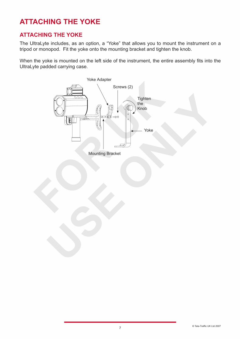
ATTACHING THE YOKE
ATTACHING THE YOKEThe UltraLyte includes, as an option, a “Yoke” that allows you to mount the instrument on a tripod or monopod. Fit the yoke onto the mounting bracket and tighten the knob.
When the yoke is mounted on the left side of the instrument, the entire assembly fits into the UltraLyte padded carrying case.
© Tele-Traffic UK Ltd 20078
POWERING ON AND OFF
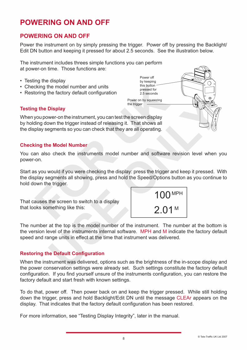
POWERING ON AND OFFPower the instrument on by simply pressing the trigger. Power off by pressing the Backlight/Edit DN button and keeping it pressed for about 2.5 seconds. See the illustration below.
The instrument includes threes simple functions you can perform at power-on time. Those functions are:
• Testing the display• Checking the model number and units• Restoring the factory default configuration
Testing the DisplayWhen you power-on the instrument, you can test the screen display by holding down the trigger instead of releasing it. That shows all the display segments so you can check that they are all operating.
Checking the Model NumberYou can also check the instruments model number and software revision level when you power-on. Start as you would if you were checking the display: press the trigger and keep it pressed. With the display segments all showing, press and hold the Speed/Options button as you continue to hold down the trigger.
That causes the screen to switch to a display that looks something like this: The number at the top is the model number of the instrument. The number at the bottom is the version level of the instruments internal software. MPH and M indicate the factory default speed and range units in effect at the time that instrument was delivered.
Restoring the Default ConfigurationWhen the instrument was delivered, options such as the brightness of the in-scope display and the power conservation settings were already set. Such settings constitute the factory default configuration. If you find yourself unsure of the instruments configuration, you can restore the factory default and start fresh with known settings.
To do that, power off. Then power back on and keep the trigger pressed. While still holding down the trigger, press and hold Backlight/Edit DN until the message CLEAr appears on the display. That indicates that the factory default configuration has been restored.
For more information, see “Testing Display Integrity”, later in the manual.
100 2.01
MPH
M
Power on by squeezing the trigger
Power off by keeping this button pressed for 2.5 seconds
© Tele-Traffic UK Ltd 20079
SCREEN INDICATORS
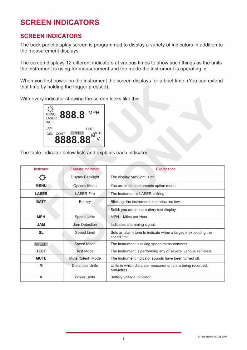
SCREEN INDICATORSThe back panel display screen is programmed to display a variety of indicators in addition to the measurement displays.
The screen displays 12 different indicators at various times to show such things as the units the instrument is using for measurement and the mode the instrument is operating in.
When you first power on the instrument the screen displays for a brief time. (You can extend that time by holding the trigger pressed).
With every indicator showing the screen looks like this:
The table indicator below lists and explains each indicator.
Explanation
You are in the instruments option menu.
The instrument’s LASER is firing.
The display backlight is on.
Blinking: the instruments batteries are low.
Solid: you are in the battery test display.
MPH – Miles per Hour
Indicates a jamming signal.
Sets an alarm tone to indicate when a target is exceeding the speed limit.
The instrument is taking speed measurements.
The instrument is performing any of several various self-tests.
Units in which distance measurements are being recorded. M=Metres.
Battery voltage indicator.
LASER Fire
Options Menu
Display Backlight
Battery
Speed Units
Jam Detection
Speed Limit
Speed Mode
Test Mode
Distances Units
Power Units
LASER
MENU
BATT
MPH
JAM
SL
TEST
M
V
Feature IndicatedIndicator
The instrument indicator sounds have been turned off.Mute (Silent) ModeMUTE
888.8
8888.88
MPH
M
LASERMENU
BATT
JAMGSL CONT
TESTMUTE
V
© Tele-Traffic UK Ltd 200710
SCREEN MENU OPTIONS
MENU OPTIONSThe following table lists the options available through the Menu/Options button:
Explanation
Artificially restricts the minimum range of the instrument.
Artificially restricts the maximum range of the instrument.
Varies the in-scope brightness.
The unit is permanently set to Metres and in Miles per Hour.
Alternate speed measurement mode in which the instrument measures the average speed of a target over an operator-determined measurement time.
Toggles instrument sounds on and off.
Toggles instrument and display time-outs on and off.
Toggles the formats in which data will be downloaded from the instrument.
Dedicated feature for instrument service.
GL
GS
br
M MPH
CONT
MUTE
ALL on
20-20Cr, UL100, UL200
rEF F out
Gate - Long
Gate - Short
Measurement Units
Continuous Mode
Mute Mode
Power Time-outs
Reference Frequency
Screen IndicatorsOption
Display Intensity
Download Formats
LISTENING TO THE INSTRUMENT
LISTENING TO THE INSTRUMENTThe UltraLyte emits a variety of ticks and tones when it takes readings. The sounds vary depending on what the instrument is doing and with experience you can tell what is happening during a measurement simply by listening.
The tones it emits are summarised in the table below.
Meaning
The instrument was unable to take the intended measurement due to an error. An error code displays on the back panel screen to indicate the nature of the error. See Error Indicators in this manual for details.
The instrument is attempting to lock onto a target.
The instrument succeeded in taking the intended measurement.
The instrument succeeded in taking a speed-reading and the target vehicle is exceeding the speed limit. (Only when a speed limit has been entered in the instrument and the feature is turned on)
Low-Pitched Growl
Single Low-Pitched Tone
Double High-Pitched Tone
Sound
Single High-Pitched Tone
© Tele-Traffic UK Ltd 200711
EDIT MODE
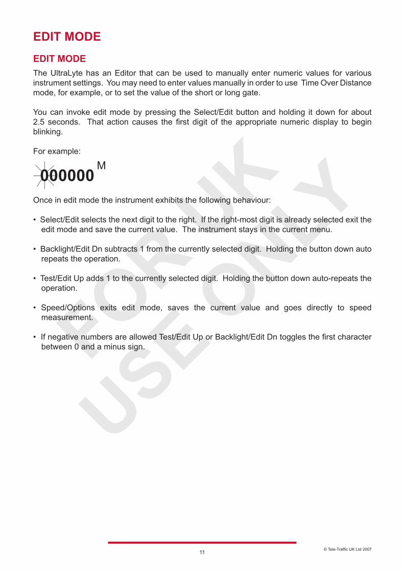
EDIT MODEThe UltraLyte has an Editor that can be used to manually enter numeric values for various instrument settings. You may need to enter values manually in order to use Time Over Distance mode, for example, or to set the value of the short or long gate.
You can invoke edit mode by pressing the Select/Edit button and holding it down for about 2.5 seconds. That action causes the first digit of the appropriate numeric display to begin blinking. For example:
Once in edit mode the instrument exhibits the following behaviour: • Select/Edit selects the next digit to the right. If the right-most digit is already selected exit the edit mode and save the current value. The instrument stays in the current menu. • Backlight/Edit Dn subtracts 1 from the currently selected digit. Holding the button down auto repeats the operation.
• Test/Edit Up adds 1 to the currently selected digit. Holding the button down auto-repeats the operation.
• Speed/Options exits edit mode, saves the current value and goes directly to speed measurement.
• If negative numbers are allowed Test/Edit Up or Backlight/Edit Dn toggles the first character between 0 and a minus sign.
000000M
© Tele-Traffic UK Ltd 200712
BASIC SPEED MEASUREMENT
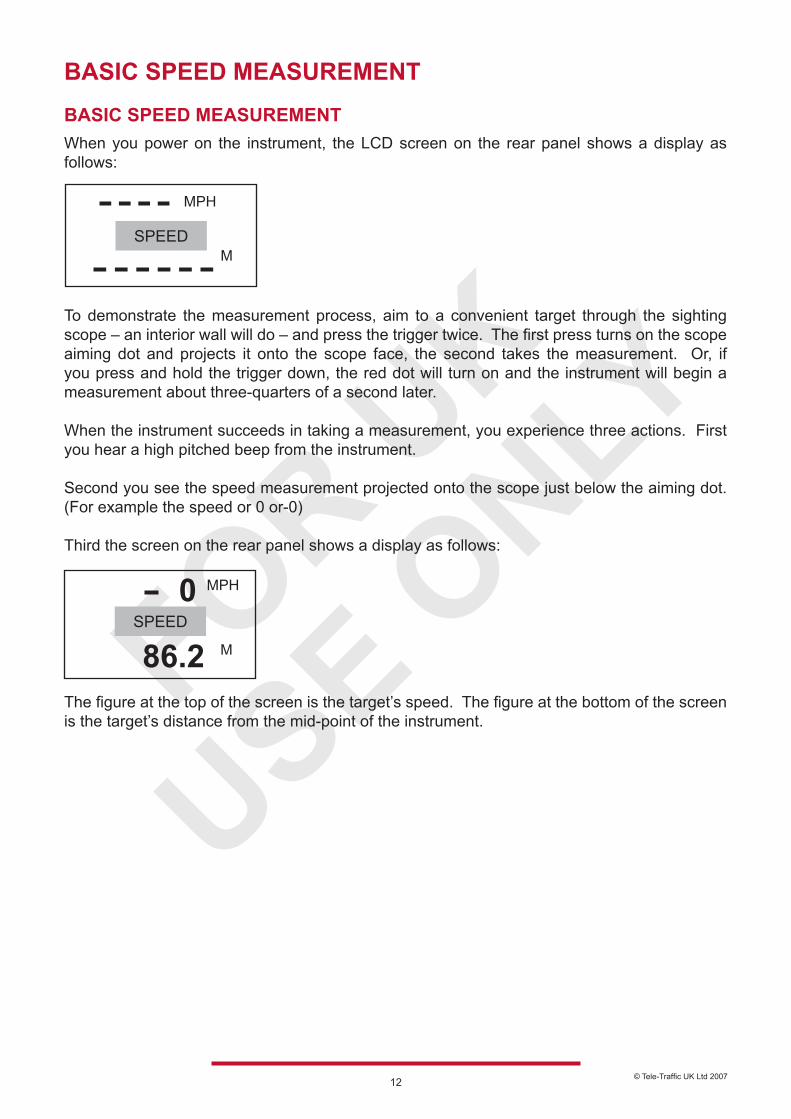
BASIC SPEED MEASUREMENTWhen you power on the instrument, the LCD screen on the rear panel shows a display as follows:
To demonstrate the measurement process, aim to a convenient target through the sighting scope – an interior wall will do – and press the trigger twice. The first press turns on the scope aiming dot and projects it onto the scope face, the second takes the measurement. Or, if you press and hold the trigger down, the red dot will turn on and the instrument will begin a measurement about three-quarters of a second later.
When the instrument succeeds in taking a measurement, you experience three actions. First you hear a high pitched beep from the instrument.
Second you see the speed measurement projected onto the scope just below the aiming dot. (For example the speed or 0 or-0)
Third the screen on the rear panel shows a display as follows:
MPH
SPEEDM
MPH
SPEED
M
0
86.2The figure at the top of the screen is the target’s speed. The figure at the bottom of the screen is the target’s distance from the mid-point of the instrument.
© Tele-Traffic UK Ltd 200713
Measuring a Moving VehicleTo measure the velocity of a vehicle using the UltraLyte use the following procedure:
1. Aim the instrument at the license plate area of the target vehicle and squeeze the trigger. A low-pitched growl begins indicating the instrument is trying to acquire a lock in the target.
2. Keep the trigger pressed and the instrument sighted on the target until you hear a beep. A high-pitched beep means that a speed was captured; a low-pitched beep that a measurement error occurred. The speed calculated for the target displays in the LCD and in the scope. If the target was going away from you when it was measured, the speed displays as a negative number. If the target was approaching, the speed displays as a positive number.
As long as the trigger is kept pressed your UltraLyte instrument may retry the speed measurement, depending on its configuration, up to 10 times or more. Consequently, it is very important that the aiming point on the target remains constant for the entire measurement time. If you move the instrument off the aiming point it cannot capture a speed reading and displays an error message instead.
Speed Limit SettingYour UltraLyte instrument has a speed limit feature that sounds an alarm when the target’s speed exceeds pre-set limit. See “Setting the Speed Limit” later in this manual for details.
The JAM IndicatorIf your instrument is configured for it, the JAM indicator on the back panel screen may blink during a measurement accompanied by the JAM tone. It indicates that the instrument is being flooded by light and has had difficulty detecting its own signal.
It means one of two things. Either you are targeting a strong light source such as headlights or a targeted vehicle is employing a LASER-Jamming device.
Regardless of the level of interference you will never get an erroneous speed-reading. At a low level of interference you will get a good speed reading even though the JAM tone sounds and the indicator blinks. At a high level of interference you will get an E07 error condition.
Line of SightYou must at all times have a clear line of sight to the target vehicle. If an object intersects the beam while a velocity measurement is being taken, an error message displays.
The Cosine EffectIf a target vehicle is moving directly toward or away from you the velocity measured by the UltraLyte is identical to the vehicle’s true speed. For safety, however the instrument is usually set up on the side of the road resulting in an angle between the instrument’s position and the target vehicle’s direction of travel. When the angle is significant the measured speed is less than the target’s true speed. The phenomenon is known as the “Cosine Effect”. (“Cosine” is a trigonometric function related to the phenomenon).
Continued
© Tele-Traffic UK Ltd 200714
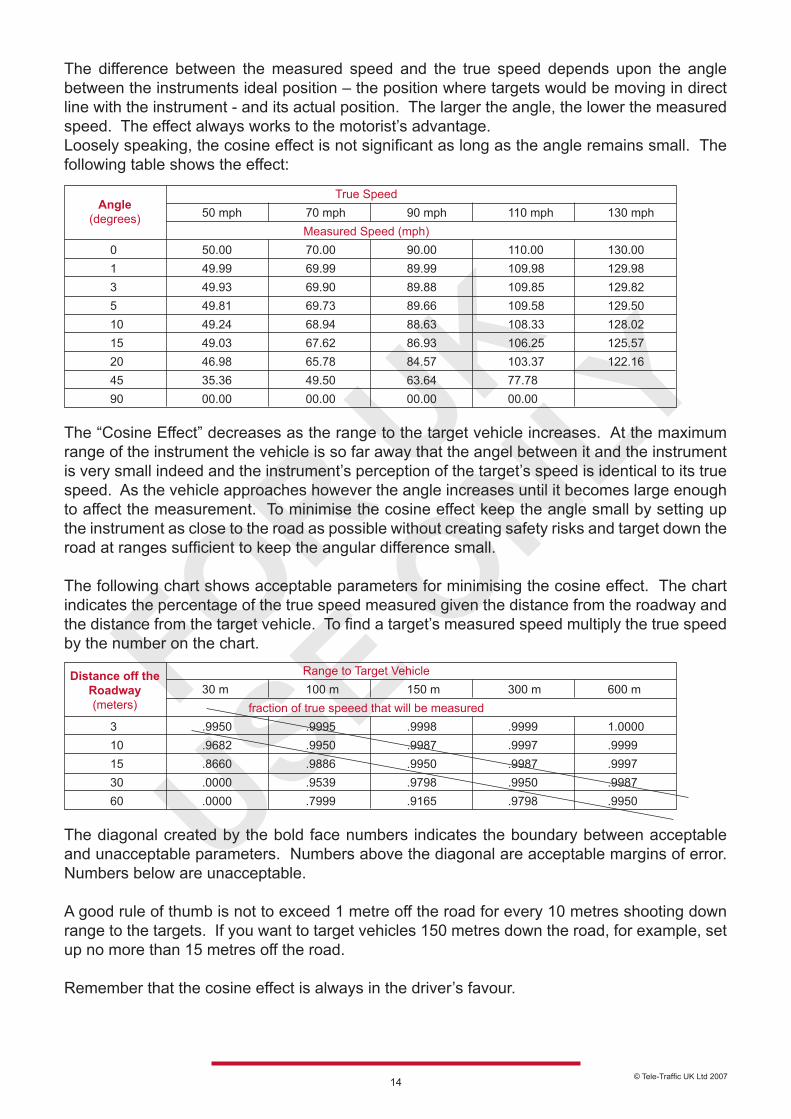
The difference between the measured speed and the true speed depends upon the angle between the instruments ideal position – the position where targets would be moving in direct line with the instrument - and its actual position. The larger the angle, the lower the measured speed. The effect always works to the motorist’s advantage.Loosely speaking, the cosine effect is not significant as long as the angle remains small. The following table shows the effect: The “Cosine Effect” decreases as the range to the target vehicle increases. At the maximum range of the instrument the vehicle is so far away that the angel between it and the instrument is very small indeed and the instrument’s perception of the target’s speed is identical to its true speed. As the vehicle approaches however the angle increases until it becomes large enough to affect the measurement. To minimise the cosine effect keep the angle small by setting up the instrument as close to the road as possible without creating safety risks and target down the road at ranges sufficient to keep the angular difference small.
The following chart shows acceptable parameters for minimising the cosine effect. The chart indicates the percentage of the true speed measured given the distance from the roadway and the distance from the target vehicle. To find a target’s measured speed multiply the true speed by the number on the chart. The diagonal created by the bold face numbers indicates the boundary between acceptable and unacceptable parameters. Numbers above the diagonal are acceptable margins of error. Numbers below are unacceptable. A good rule of thumb is not to exceed 1 metre off the road for every 10 metres shooting down range to the targets. If you want to target vehicles 150 metres down the road, for example, set up no more than 15 metres off the road. Remember that the cosine effect is always in the driver’s favour.
True Speed 50 mph 70 mph 90 mph 110 mph 130 mph
Measured Speed (mph) 0 50.00 70.00 90.00 110.00 130.00 1 49.99 69.99 89.99 109.98 129.98 3 49.93 69.90 89.88 109.85 129.82 5 49.81 69.73 89.66 109.58 129.50 10 49.24 68.94 88.63 108.33 128.02 15 49.03 67.62 86.93 106.25 125.57 20 46.98 65.78 84.57 103.37 122.16 45 35.36 49.50 63.64 77.78 90 00.00 00.00 00.00 00.00
Angle(degrees)
Range to Target Vehicle 30 m 100 m 150 m 300 m 600 m
fraction of true speeed that will be measured 3 .9950 .9995 .9998 .9999 1.0000 10 .9682 .9950 .9987 .9997 .9999 15 .8660 .9886 .9950 .9987 .9997 30 .0000 .9539 .9798 .9950 .9987 60 .0000 .7999 .9165 .9798 .9950
Distance off theRoadway(meters)
© Tele-Traffic UK Ltd 200715
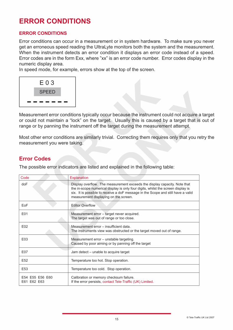
ERROR CONDITIONSERROR CONDITIONSError conditions can occur in a measurement or in system hardware. To make sure you never get an erroneous speed reading the UltraLyte monitors both the system and the measurement. When the instrument detects an error condition it displays an error code instead of a speed. Error codes are in the form Exx, where ”xx” is an error code number. Error codes display in the numeric display area.In speed mode, for example, errors show at the top of the screen.
Measurement error conditions typically occur because the instrument could not acquire a target or could not maintain a “lock” on the target. Usually this is caused by a target that is out of range or by panning the instrument off the target during the measurement attempt.
Most other error conditions are similarly trivial. Correcting them requires only that you retry the measurement you were taking.
Error CodesThe possible error indicators are listed and explained in the following table:
E 0 3SPEED
Code Explanation
doF EoF E01 E02 E03 E07 E52 E53 E54 E55 E56 E60 E61 E62 E63
Display overflow. The measurement exceeds the display capacity. Note that the in-scope numerical display is only four digits, whilst the screen display is six. It is possible to receive a doF message in the Scope and still have a valid measurement displaying on the screen. Editor Overflow Measurement error – target never acquired. The target was out of range or too close. Measurement error – insufficient data. The instruments view was obstructed or the target moved out of range. Measurement error – unstable targeting. Caused by poor aiming or by panning off the target Jam detect – unable to acquire target Temperature too hot. Stop operation. Temperature too cold. Stop operation. Calibration or memory checksum failure. If the error persists, contact Tele-Traffic (UK) Limited.
© Tele-Traffic UK Ltd 200716
RFI ConsiderationsThe UltraLyte does not display a specific error message indicating the presence of radio frequency interference (RFI). The instrument’s electronics have been designed for optimum RFI immunity. If RFI is present it generated one of the above error codes to display. The exact code is dependent upon the level and nature of the RFI.
IN-SCOPE DISPLAY INTENSITY
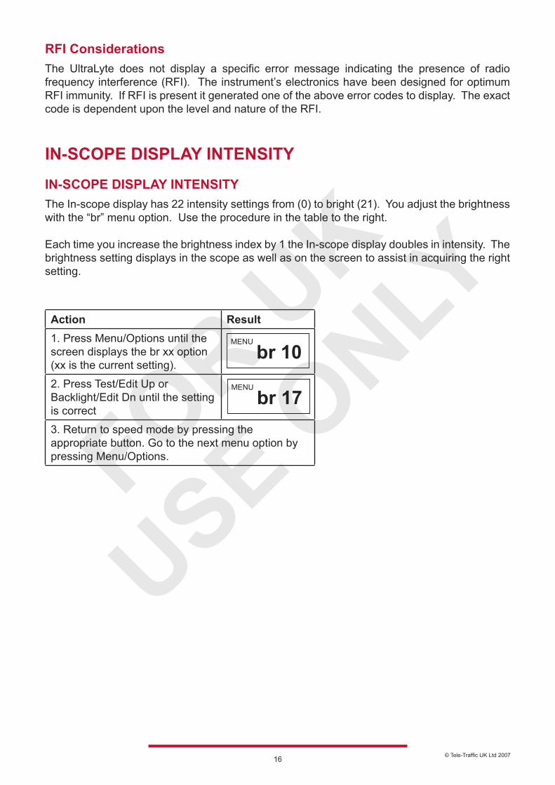
IN-SCOPE DISPLAY INTENSITYThe In-scope display has 22 intensity settings from (0) to bright (21). You adjust the brightness with the “br” menu option. Use the procedure in the table to the right.
Each time you increase the brightness index by 1 the In-scope display doubles in intensity. The brightness setting displays in the scope as well as on the screen to assist in acquiring the right setting.
Action Result1. Press Menu/Options until the screen displays the br xx option (xx is the current setting).
2. Press Test/Edit Up or Backlight/Edit Dn until the setting is correct
3. Return to speed mode by pressing the appropriate button. Go to the next menu option by pressing Menu/Options.
MENU
br 10MENU
br 17
© Tele-Traffic UK Ltd 200717
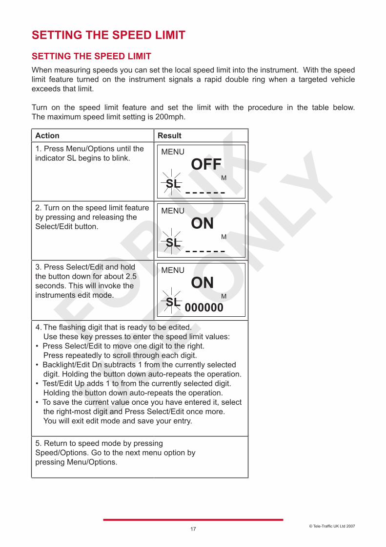
SETTING THE SPEED LIMIT
SETTING THE SPEED LIMITWhen measuring speeds you can set the local speed limit into the instrument. With the speed limit feature turned on the instrument signals a rapid double ring when a targeted vehicle exceeds that limit.
Turn on the speed limit feature and set the limit with the procedure in the table below. The maximum speed limit setting is 200mph.
Action Result1. Press Menu/Options until the indicator SL begins to blink.
2. Turn on the speed limit feature by pressing and releasing the Select/Edit button.
3. Press Select/Edit and hold the button down for about 2.5 seconds. This will invoke the instruments edit mode.
5. Return to speed mode by pressingSpeed/Options. Go to the next menu option bypressing Menu/Options.
MSLOFF
MENU
MSLON
MENU
MSLON
MENU
0000004. The flashing digit that is ready to be edited. Use these key presses to enter the speed limit values:• Press Select/Edit to move one digit to the right. Press repeatedly to scroll through each digit.• Backlight/Edit Dn subtracts 1 from the currently selected digit. Holding the button down auto-repeats the operation.• Test/Edit Up adds 1 to from the currently selected digit. Holding the button down auto-repeats the operation.• To save the current value once you have entered it, select the right-most digit and Press Select/Edit once more. You will exit edit mode and save your entry.
© Tele-Traffic UK Ltd 200718
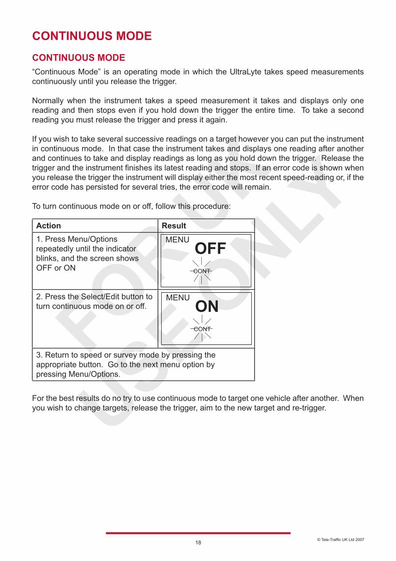
CONTINUOUS MODE CONTINUOUS MODE“Continuous Mode” is an operating mode in which the UltraLyte takes speed measurements continuously until you release the trigger.
Normally when the instrument takes a speed measurement it takes and displays only one reading and then stops even if you hold down the trigger the entire time. To take a second reading you must release the trigger and press it again.
If you wish to take several successive readings on a target however you can put the instrument in continuous mode. In that case the instrument takes and displays one reading after another and continues to take and display readings as long as you hold down the trigger. Release the trigger and the instrument finishes its latest reading and stops. If an error code is shown when you release the trigger the instrument will display either the most recent speed-reading or, if the error code has persisted for several tries, the error code will remain.
To turn continuous mode on or off, follow this procedure: For the best results do no try to use continuous mode to target one vehicle after another. When you wish to change targets, release the trigger, aim to the new target and re-trigger.
Action Result1. Press Menu/Options repeatedly until the indicator blinks, and the screen shows OFF or ON
2. Press the Select/Edit button to turn continuous mode on or off.
3. Return to speed or survey mode by pressing theappropriate button. Go to the next menu option bypressing Menu/Options.
CONT
OFFMENU
CONT
ONMENU
© Tele-Traffic UK Ltd 200719
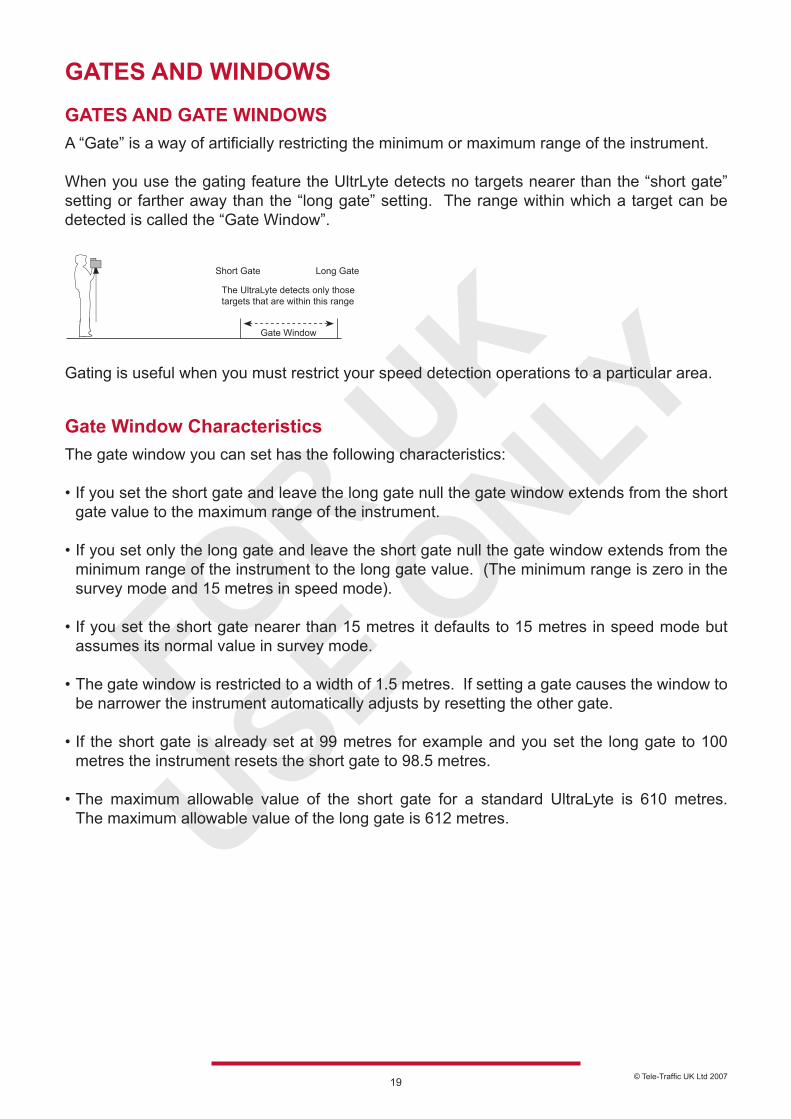
GATES AND WINDOWS
GATES AND GATE WINDOWSA “Gate” is a way of artificially restricting the minimum or maximum range of the instrument.
When you use the gating feature the UltrLyte detects no targets nearer than the “short gate” setting or farther away than the “long gate” setting. The range within which a target can be detected is called the “Gate Window”.
Gating is useful when you must restrict your speed detection operations to a particular area.
Gate Window CharacteristicsThe gate window you can set has the following characteristics:
• If you set the short gate and leave the long gate null the gate window extends from the short gate value to the maximum range of the instrument.
• If you set only the long gate and leave the short gate null the gate window extends from the minimum range of the instrument to the long gate value. (The minimum range is zero in the survey mode and 15 metres in speed mode). • If you set the short gate nearer than 15 metres it defaults to 15 metres in speed mode but assumes its normal value in survey mode.
• The gate window is restricted to a width of 1.5 metres. If setting a gate causes the window to be narrower the instrument automatically adjusts by resetting the other gate.
• If the short gate is already set at 99 metres for example and you set the long gate to 100 metres the instrument resets the short gate to 98.5 metres.
• The maximum allowable value of the short gate for a standard UltraLyte is 610 metres. The maximum allowable value of the long gate is 612 metres.
Gate Window
The UltraLyte detects only those targets that are within this range
Short Gate Long Gate
© Tele-Traffic UK Ltd 200720
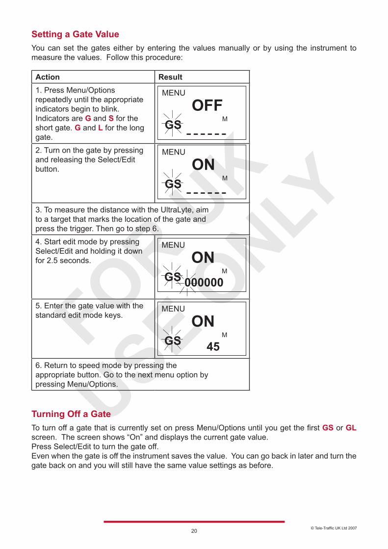
Setting a Gate ValueYou can set the gates either by entering the values manually or by using the instrument to measure the values. Follow this procedure:
Action Result1. Press Menu/Options repeatedly until the appropriate indicators begin to blink. Indicators are G and S for the short gate. G and L for the long gate.
2. Turn on the gate by pressing and releasing the Select/Edit button.
3. To measure the distance with the UltraLyte, aim to a target that marks the location of the gate andpress the trigger. Then go to step 6.
4. Start edit mode by pressing Select/Edit and holding it down for 2.5 seconds.
5. Enter the gate value with the standard edit mode keys.
6. Return to speed mode by pressing theappropriate button. Go to the next menu option bypressing Menu/Options.
MGSOFF
MENU
MGSON
MENU
MGSON
MENU
000000
MGSON
MENU
45
Turning Off a GateTo turn off a gate that is currently set on press Menu/Options until you get the first GS or GL screen. The screen shows “On” and displays the current gate value.Press Select/Edit to turn the gate off.Even when the gate is off the instrument saves the value. You can go back in later and turn the gate back on and you will still have the same value settings as before.
© Tele-Traffic UK Ltd 200721
MUTING THE INSTRUMENT
MUTING THE INSTRUMENTWhen the UltraLyte is taking readings it normally makes a variety of audible signals to help inform you of its operational condition. High-pitched beeps signal a successful measurement and low-pitched beeps indicate an error.
If you prefer the instrument to be silent or if you are in relatively close quarters with potential targets, i.e. pedestrians or cyclists, who might be warned or startled by noise from the instrument you can mute the instrument so it makes no noise.
When mute is on LAS appears in the scope to let you know that the laser is firing.Next the in-scope-aiming dot disappears to let you know that the measurement has completed, an indication similar to the high or low pitch tome in normal mode.
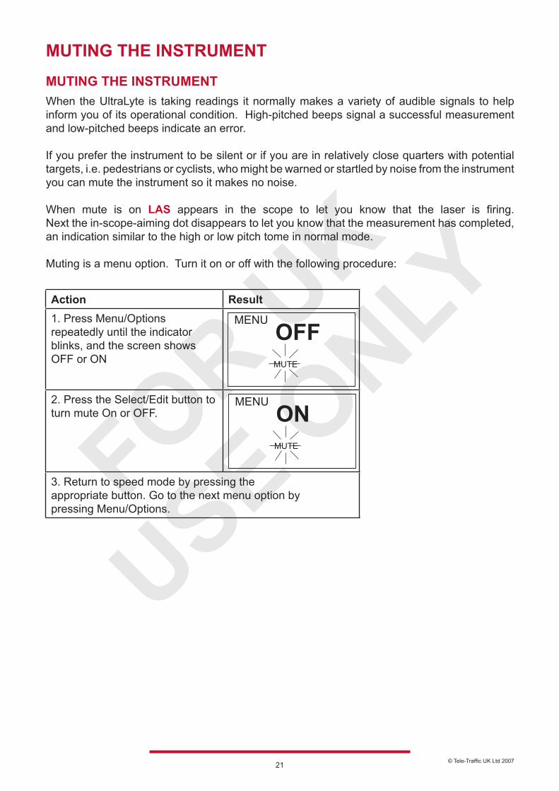
Muting is a menu option. Turn it on or off with the following procedure:
Action Result1. Press Menu/Options repeatedly until the indicator blinks, and the screen shows OFF or ON
2. Press the Select/Edit button to turn mute On or OFF.
3. Return to speed mode by pressing theappropriate button. Go to the next menu option bypressing Menu/Options.
MUTE
OFFMENU
MUTE
ONMENU
© Tele-Traffic UK Ltd 200722
POWER CONSERVATION INTERVALS
POWER CONSERVATION INTERVALSTo help conserve the batteries the UltraLyte has three times power off intervals; one for the in-scope numerical display, one for the in-scope aiming dot and one for the instrument as a whole. Lack of instrument activity for an interval causes the associated function to shut down.The following table summarises the time outs:
Function Interval Effect of Time-outIn-scope numerical display 3 sec The numerical display shuts offIn-scope Aiming dot 20 sec Aiming dot shuts offInstrument 10 mins (approx.) Power shuts down
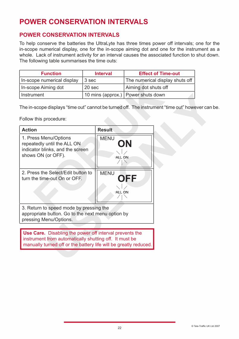
The in-scope displays “time out” cannot be turned off. The instrument “time out” however can be. Follow this procedure:
Action Result1. Press Menu/Options repeatedly until the ALL ON indicator blinks, and the screen shows ON (or OFF).
2. Press the Select/Edit button to turn the time-out On or OFF.
3. Return to speed mode by pressing theappropriate button. Go to the next menu option bypressing Menu/Options.
ALL ON
ONMENU
ALL ON
OFFMENU
Use Care. Disabling the power off interval prevents the instrument from automatically shutting off. It must be manually turned off or the battery life will be greatly reduced.

© Tele-Traffic UK Ltd 200723
TESTING DISPLAY INTEGRITY TESTING DISPLAY INTEGRITYThe back panel and in-scope displays are segmented. A test has been incorporated into the instrument to verify that all segments are operating.
To initiate the test press Test/Options. The screen displays the following: Press Select/Edit to toggle the displays on and off. If you do not toggle off the in-scope display times out after 5 seconds.
If any segment fails to display contact: Tele-Traffic (UK) Limited to arrange repair. Telephone 01926 407272.
NOTE: You may also test the back panel display integrity at power on by holding the trigger pressed.
SCOPE ALIGNMENT TEST
SCOPE ALIGNMENT TESTThis test ensures the accuracy of the UltraLyte’s targeting mechanics and should be performed periodically.
1. Put the Instrument in Test Tone ModePress the Test/Options button repeatedly until the display reads “tt” which stands for test tone. When test tone mode is active pressing the trigger generates an audible tone. The tone’s pitch is related to the strength of the laser pulse returned to the instrument. A high tone indicates a strong return, a low tone indicates a weak tone.
2. Select a TargetChoose a prominent target with definitive horizontal and vertical edges. The target’s reflective qualities and distance from you should be such that you can clearly hear a change in the pitch of the test tone when you pan the instrument over the edges of the target. (A telephone pole is an excellent choice). Make sure there is nothing behind the target that the instrument might detect so you know without doubt that any change in pitch is due strictly to the target.
3. Scan the TargetPress and hold the trigger while panning the instrument across the target. The tone changes pitch when the instrument acquires the target. The highest pitch (the “on target” tone) should occur when the scope’s red aiming dot is centred on target.
Scan the target both horizontally and vertically making certain the pitch decreases evenly off each side of the target. If there is any discrepancy between the “on target” tone and the position of the red aiming dot perform the realignment procedure.
(See “Realigning the Scope” on page 28). NOTE Tele-Traffic recommends that this test be performed before and after each enforcement session.
888.8
8888.88
MPH
M
LASERMENU
BATTJAM
SLTEST
MUTE
V
© Tele-Traffic UK Ltd 200724
BATTERY VOLTAGE DETECTION
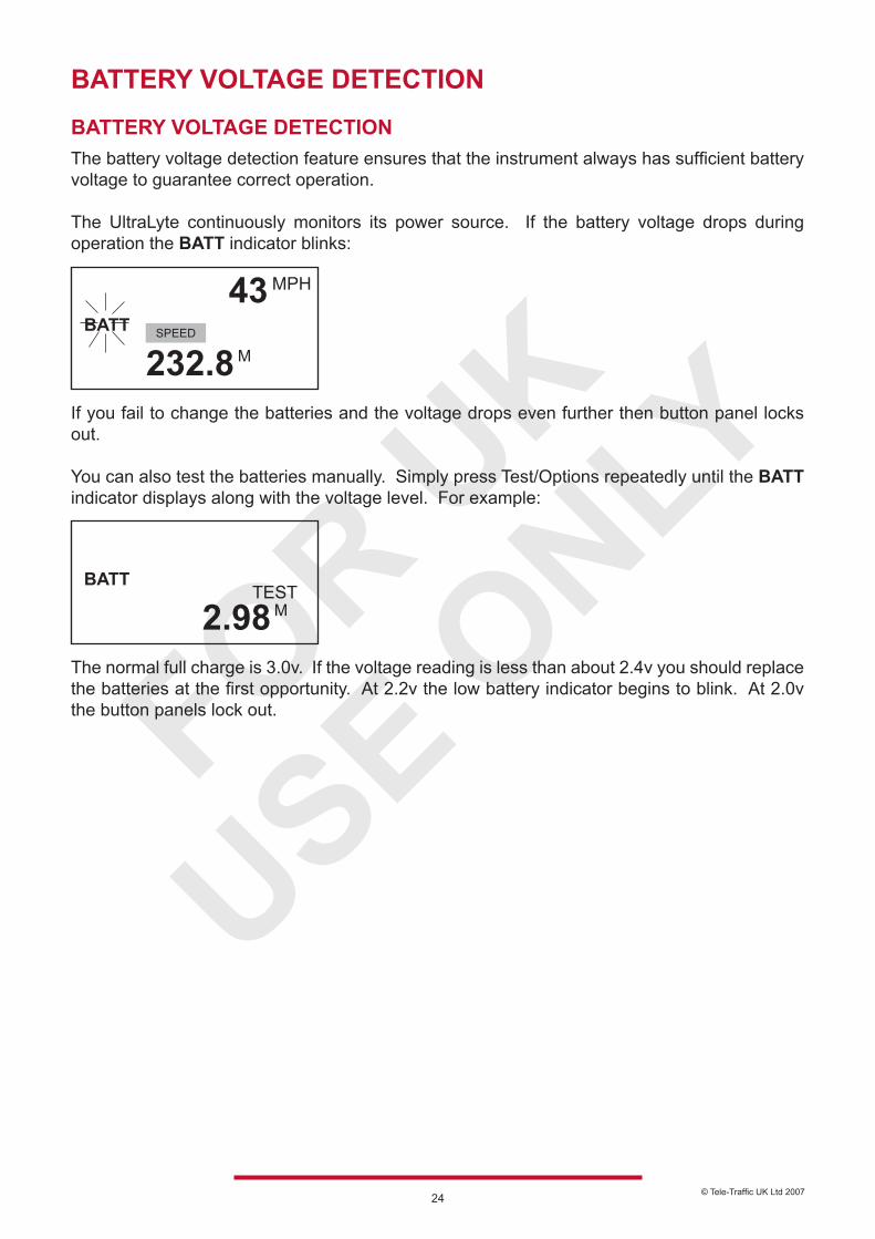
BATTERY VOLTAGE DETECTIONThe battery voltage detection feature ensures that the instrument always has sufficient battery voltage to guarantee correct operation.
The UltraLyte continuously monitors its power source. If the battery voltage drops during operation the BATT indicator blinks:
If you fail to change the batteries and the voltage drops even further then button panel locks out.
You can also test the batteries manually. Simply press Test/Options repeatedly until the BATT indicator displays along with the voltage level. For example:
The normal full charge is 3.0v. If the voltage reading is less than about 2.4v you should replace the batteries at the first opportunity. At 2.2v the low battery indicator begins to blink. At 2.0v the button panels lock out.
BATT
MPH
M
43
232.8SPEED
BATTM2.98
TEST
© Tele-Traffic UK Ltd 200725
INSTRUMENT CONFIDENCE CHECK
INSTRUMENT CONFIDENCE CHECKThe measurement accuracy of a Light Detection and Ranging (LIDAR) instrument can be verified by several methods. Verifying it directly however, by measuring the velocity of an object travelling at a known speed, is seldom practical. The nature of LIDAR is such that it cannot be tricked by a vibrating object such as a tuning fork into displaying a velocity. For those reasons LTI has designed a passive test procedure.
The passive test is the fixed distance check.
The point of the test is to verify the accuracy of the two key elements of LIDAR speed measurement; precise time measurements and the ability to make mathematical calculations.
Tele-Traffic recommends that this test be performed at regular intervals (daily). We also suggest a test area be permanently installed in a convenient location. The test area must establish a permanent known distance between a target and a shooting mark.
Keep in mind that the minimum measurement distance for this test is 23 metres.
A target can be any flat permanent structure (a sign or a wall for example) painted with a bull’s eye or other aiming point. The shooting mark is where an operator stands to conduct the test and can be an X painted on the pavement.Testing and test area specifics are discussed below. There are two things you should note however.
First the distances specified are horizontal distances. (A horizontal distance is measured along a straight and level path from the shooting mark to the centre of the aiming point). Second the manner in which you stand and the manner in which you hold the instrument both effect the test measurements. For exact readings carefully hold the instrument so it is directly over the middle of the X.
© Tele-Traffic UK Ltd 200726
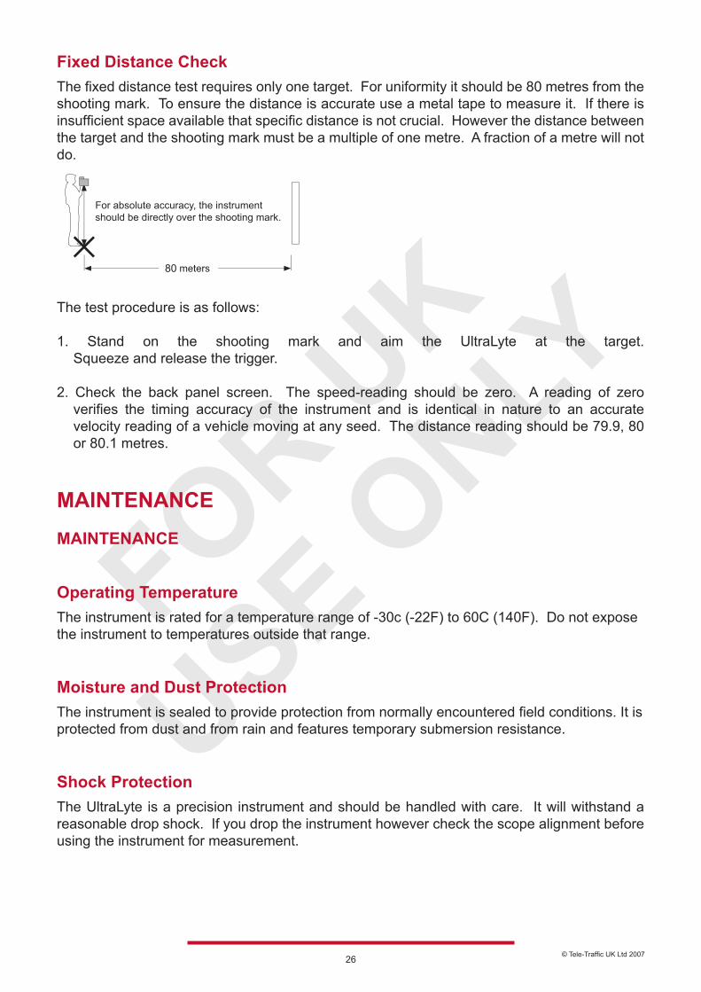
Fixed Distance CheckThe fixed distance test requires only one target. For uniformity it should be 80 metres from the shooting mark. To ensure the distance is accurate use a metal tape to measure it. If there is insufficient space available that specific distance is not crucial. However the distance between the target and the shooting mark must be a multiple of one metre. A fraction of a metre will not do.
The test procedure is as follows:
1. Stand on the shooting mark and aim the UltraLyte at the target. Squeeze and release the trigger.
2. Check the back panel screen. The speed-reading should be zero. A reading of zero verifies the timing accuracy of the instrument and is identical in nature to an accurate velocity reading of a vehicle moving at any seed. The distance reading should be 79.9, 80 or 80.1 metres.
MAINTENANCE
MAINTENANCE
Operating TemperatureThe instrument is rated for a temperature range of -30c (-22F) to 60C (140F). Do not expose the instrument to temperatures outside that range.
Moisture and Dust ProtectionThe instrument is sealed to provide protection from normally encountered field conditions. It is protected from dust and from rain and features temporary submersion resistance.
Shock ProtectionThe UltraLyte is a precision instrument and should be handled with care. It will withstand a reasonable drop shock. If you drop the instrument however check the scope alignment before using the instrument for measurement.
80
© Tele-Traffic UK Ltd 200727
Cleaning and StorageClean the instrument after each use before returning it to its case. Check for the following:
• Excess Moisture Towel off excess moisture and air dry the instrument at room temperature.
• Exterior Dirt Wipe exterior surfaces clean. Use isopropanol to remove dirt and fingerprints from the scope exterior.
• Dirty Lenses Use a lens brush to remove surface dust and loose particles from the front panel lenses. To clean a lens, moisten it with lens cleaning solution and wipe it with a clean cloth or lens tissue.
• Batteries If you will not be using the instrument again soon remove the batteries before storing it. Caring for the ScopeDo not attempt to lubricate the scope. It is sealed from within using O rings and special compounds. All seals are permanent and require no maintenance. Use a lens brush to remove surface dust and loose particles. To clean a lens, moisten it with lens cleaning solution and wipe it with a clean cloth or lens tissue. The adjustment screws are permanently lubricated. Do not attempt to lubricate them. Keep the cover screws and sealing washers in place except when the scope is being aligned.
Checking the Display ScreenThe instrument provides a method of verifying the display integrity. You can do that as described earlier in this manual in “Powering On and Off” and in “Testing Display Integrity”.
Resetting the Factory Default OptionsThe instrument remembers option settings even with the power turned off. To return options to their factory defaults use the procedure earlier in this manual in ‘Restoring the Default Configuration’.
© Tele-Traffic UK Ltd 200728
REALIGNING THE SCOPE
REALIGNING THE SCOPEThe scope may become misaligned by a heavy blow to the instrument. The procedure in the table below corrects the alignment. The point of the procedure is to align the laser’s point of impact with the red aiming dot in the scope using sound to indicate when the scope is on target. To align the scope properly you need:
• Two metric Allen Keys to expose and turn the scope adjustment screws, one 2.5mm and one 1.5mm.• A target at which to aim the instrument.• A highly stable base for the instrument. A tripod is recommended.
Target SelectionChoose your alignment target carefully. The target should be at least 200 metres away. It should be a prominent target with definitive horizontal and vertical edges that will cause a clearly perceivable change in the pitch of the test tone. (A telephone pole is an excellent choice). Make certain there are no background objects that the instrument might defect.
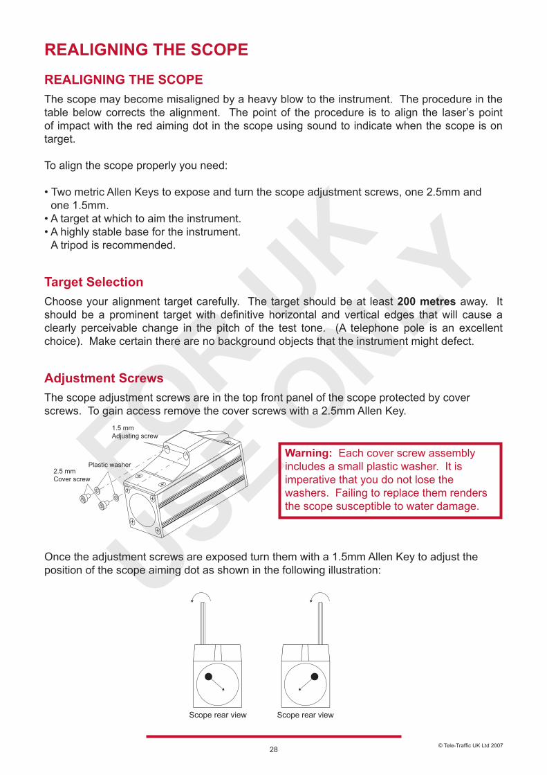
Adjustment ScrewsThe scope adjustment screws are in the top front panel of the scope protected by cover screws. To gain access remove the cover screws with a 2.5mm Allen Key. Once the adjustment screws are exposed turn them with a 1.5mm Allen Key to adjust the position of the scope aiming dot as shown in the following illustration:
Warning: Each cover screw assembly includes a small plastic washer. It is imperative that you do not lose the washers. Failing to replace them renders the scope susceptible to water damage.
© Tele-Traffic UK Ltd 200729
REALIGNING THE SCOPE
REALIGNMENT PROCEDURE
Action Result/Note1. Steady the instrument on a solid base. Rest the instrument against a solid support
that will help keep the aiming dot steady on the target.
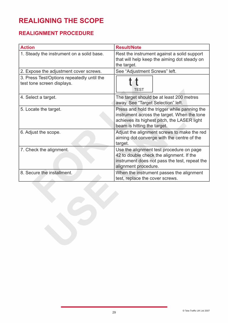
2. Expose the adjustment cover screws. See “Adjustment Screws” left.3. Press Test/Options repeatedly until the test tone screen displays.
4. Select a target. The target should be at least 200 metres away. See “Target Selection” left.
5. Locate the target. Press and hold the trigger while panning the instrument across the target. When the tone achieves its highest pitch, the LASER light beam is hitting the target.
6. Adjust the scope. Adjust the alignment screws to make the red aiming dot converge with the centre of the target.
7. Check the alignment. Use the alignment test procedure on page 42 to double check the alignment. If the instrument does not pass the test, repeat the alignment procedure.
8. Secure the installment. When the instrument passes the alignment test, replace the cover screws.
TESTt t
© Tele-Traffic UK Ltd 200730
SPECIFICATIONS Specifications Note: These specifications are subject to change.
Weight: 1.34kgSize: 21 x 7 x 28 cmAcquisition Time: < 0.4 secSpeed Accuracy: +- 1mphMin. Range: 23 metresMax. Range: 610 metresRange Accuracy: 0 – 299 mphRange Resolution: 0.1 metresBeam Divergence: 3 milliradiansLASER Wavelength: 904 nanometresTemperature Range: - 30C to + 60C (-22F to + 140F)Power: Two alkaline or NiCad rechargeable ‘C’ cells providing up to 25 hours of cordless operation.Eye safety: FDA Class 1 (CFR 21) EN 60 825Environment: Waterproof to IP 67 and NEMA 6Construction: All aluminium extruding housing
TELE-TRAFFIC (UK) LIMITEDLaserTec Centre,C2 Harris Road
WarwickCV34 5JU
Telephone: (01926) 407272Fax: (01926) 407977
Email: [email protected]: www.teletrafficuk.com


