44
User Manual UBC-222 The Gateway Solution for IoT

User Manual
UBC-222
The Gateway Solution for IoT
CopyrightThe documentation and the software included with this product are copyrighted 2016by Advantech Co., Ltd. All rights are reserved. Advantech Co., Ltd. reserves the rightto make improvements in the products described in this manual at any time withoutnotice. No part of this manual may be reproduced, copied, translated or transmittedin any form or by any means without the prior written permission of Advantech Co.,Ltd. Information provided in this manual is intended to be accurate and reliable. How-ever, Advantech Co., Ltd. assumes no responsibility for its use, nor for any infringe-ments of the rights of third parties, which may result from its use.
AcknowledgementsIntel is trademark of Intel Corporation.
All other product names or trademarks are properties of their respective owners.
For more information about this and other Advantech products, please visit our web-site at:
http://www.advantech.com/
http://www.advantech.com/ePlatform/
For technical support and service, please visit our support website at:
http://support.advantech.com.tw/support/
Part No. 2006222N00 Edition 1
Printed in Taiwan August 2016
UBC-222 User Manual ii
Product Warranty (2 years)Advantech warrants to you, the original purchaser, that each of its products will befree from defects in materials and workmanship for two years from the date of pur-chase.
This warranty does not apply to any products which have been repaired or altered bypersons other than repair personnel authorized by Advantech, or which have beensubject to misuse, abuse, accident or improper installation. Advantech assumes noliability under the terms of this warranty as a consequence of such events.
Because of Advantech’s high quality-control standards and rigorous testing, most ofour customers never need to use our repair service. If an Advantech product is defec-tive, it will be repaired or replaced at no charge during the warranty period. For out-of-warranty repairs, you will be billed according to the cost of replacement materials,service time and freight. Please consult your dealer for more details.
If you think you have a defective product, follow these steps:
1. Collect all the information about the problem encountered. (For example, CPU speed, Advantech products used, other hardware and software used, etc.) Note anything abnormal and list any onscreen messages you get when the problem occurs.
2. Call your dealer and describe the problem. Please have your manual, product, and any helpful information readily available.
3. If your product is diagnosed as defective, obtain an RMA (return merchandize authorization) number from your dealer. This allows us to process your return more quickly.
4. Carefully pack the defective product, a fully-completed Repair and Replacement Order Card and a photocopy proof of purchase date (such as your sales receipt) in a shippable container. A product returned without proof of the purchase date is not eligible for warranty service.
5. Write the RMA number visibly on the outside of the package and ship it prepaid to your dealer.
iii UBC-222 User Manual
Declaration of Conformity
FCC Class B
Note: This equipment has been tested and found to comply with the limits for a ClassB digital device, pursuant to part 15 of the FCC Rules. These limits are designed toprovide reasonable protection against harmful interference in a residential installa-tion. This equipment generates, uses and can radiate radio frequency energy and, ifnot installed and used in accordance with the instructions, may cause harmful inter-ference to radio communications. However, there is no guarantee that interferencewill not occur in a particular installation. If this equipment does cause harmful interfer-ence to radio or television reception, which can be determined by turning the equip-ment off and on, the user is encouraged to try to correct the interference by one ormore of the following measures:
Reorient or relocate the receiving antenna. Increase the separation between the equipment and receiver. Connect the equipment into an outlet on a circuit different from that to which the
receiver is connected. Consult the dealer or an experienced radio/TV technician for help.
Technical Support and Assistance1. Visit the Advantech website at http://support.advantech.com where you can find
the latest information about the product.2. Contact your distributor, sales representative, or Advantech's customer service
center for technical support if you need additional assistance. Please have the following information ready before you call:– Product name and serial number– Description of your peripheral attachments– Description of your software (operating system, version, application software,
etc.)– A complete description of the problem– The exact wording of any error messages
UBC-222 User Manual iv

Warnings, Cautions and Notes
Packing ListBefore setting up the system, check that the items listed below are included and ingood condition. If any item does not accord with the table, please contact yourdealer immediately. 1x UBC-222 unit with Wall mount bracket
Ordering Information
Optional Accessories
Warning! Warnings indicate conditions, which if not observed, can cause personal injury!
Caution! Cautions are included to help you avoid damaging hardware or losing data. e.g.
There is a danger of a new battery exploding if it is incorrectly installed. Do not attempt to recharge, force open, or heat the battery. Replace the battery only with the same or equivalent type recommended by the man-ufacturer. Discard used batteries according to the manufacturer's instructions.
Note! Notes provide optional additional information.
Model Number Description
UBC-222NS-GLA1E Intel Quark x1000 400MHz
Model Number Description
XRISC-ADP-10HW-AG USB power adapter 100-240V +5.35V 2A
1700025431-01 USB to DC-in cable
1700021565-01 Debug cable (DB-9 type)
SQF-ISDS1-2G-86E SQFlash SD card SLC 2G (-40 ~ 85° C)
v UBC-222 User Manual

Safety Instructions1. Read these safety instructions carefully.2. Keep this User Manual for later reference.3. Disconnect this equipment from any AC outlet before cleaning. Use a damp
cloth. Do not use liquid or spray detergents for cleaning.4. For plug-in equipment, the power outlet socket must be located near the equip-
ment and must be easily accessible.5. Keep this equipment away from humidity.6. Put this equipment on a reliable surface during installation. Dropping it or letting
it fall may cause damage.7. The openings on the enclosure are for air convection. Protect the equipment
from overheating. DO NOT COVER THE OPENINGS.8. Make sure the voltage of the power source is correct before connecting the
equipment to the power outlet.9. Position the power cord so that people cannot step on it. Do not place anything
over the power cord.10. All cautions and warnings on the equipment should be noted.11. If the equipment is not used for a long time, disconnect it from the power source
to avoid damage by transient overvoltage.12. Never pour any liquid into an opening. This may cause fire or electrical shock.13. Never open the equipment. For safety reasons, the equipment should be
opened only by qualified service personnel.14. If one of the following situations arises, get the equipment checked by service
personnel:The power cord or plug is damaged.Liquid has penetrated into the equipment.The equipment has been exposed to moisture.The equipment does not work well, or you cannot get it to work according to
the user's manual.The equipment has been dropped and damaged.The equipment has obvious signs of breakage.
15. DO NOT LEAVE THIS EQUIPMENT IN AN ENVIRONMENT WHERE THE STORAGE TEMPERATURE MAY GO BELOW -20° C (-4° F) OR ABOVE 60° C (140° F). THIS COULD DAMAGE THE EQUIPMENT. THE EQUIPMENT SHOULD BE IN A CONTROLLED ENVIRONMENT.
16. CAUTION: DANGER OF EXPLOSION IF BATTERY IS INCORRECTLY REPLACED. REPLACE ONLY WITH THE SAME OR EQUIVALENT TYPE RECOMMENDED BY THE MANUFACTURER, DISCARD USED BATTERIES ACCORDING TO THE MANUFACTURER'S INSTRUCTIONS.
The sound pressure level at the operator's position according to IEC 704-1:1982 isno more than 70 dB (A).
DISCLAIMER: This set of instructions is given according to IEC 704-1. Advantechdisclaims all responsibility for the accuracy of any statements contained herein.
UBC-222 User Manual vi

Safety Precaution - Static ElectricityFollow these simple precautions to protect yourself from harm and the products fromdamage.
To avoid electrical shock, always disconnect the power from your PC chassis before you work on it. Don't touch any components on the CPU card or other cards while the PC is on.
Disconnect power before making any configuration changes. The sudden rush of power as you connect a jumper or install a card may damage sensitive elec-tronic components.
vii UBC-222 User Manual

UBC-222 User Manual viii
Contents
Chapter 1 General Introduction ...........................11.1 Introduction ............................................................................................... 21.2 Product Features....................................................................................... 2
1.2.1 Key Features................................................................................. 21.2.2 General ......................................................................................... 21.2.3 Ethernet ........................................................................................ 21.2.4 Power Consumption...................................................................... 3
1.3 Mechanical Specification........................................................................... 31.3.1 Dimensions ................................................................................... 31.3.2 Weight........................................................................................... 3
1.4 Power Requirements................................................................................. 41.4.1 System Power............................................................................... 41.4.2 RTC Battery .................................................................................. 4
1.5 Environment Specifications....................................................................... 41.5.1 Operating Temperature................................................................. 41.5.2 Relative Humidity .......................................................................... 41.5.3 Storage Temperature.................................................................... 41.5.4 Vibration Loading during Operation .............................................. 41.5.5 EMC.............................................................................................. 4
Chapter 2 Hardware Functionality.......................52.1 Introduction ............................................................................................... 62.2 UBC-222 I/O Indication ............................................................................. 6
Figure 2.1 UBC-222 front view .................................................... 6Figure 2.2 UBC-222 LED indication............................................. 6Figure 2.3 UBC-222 left side view ............................................... 6
2.3 UBC-222 I/O Connectors .......................................................................... 72.3.1 Power Input Connector ................................................................. 7
Figure 2.4 Power input connector................................................ 72.3.2 COM Connector ............................................................................ 7
Figure 2.5 COM connector .......................................................... 7Table 2.1: COM Connector Pin Assignment................................ 7
2.3.3 Debug Console ............................................................................. 8Table 2.2: Debug Console Pin Assignment................................. 8
2.3.4 SPI ................................................................................................ 8Table 2.3: SPI Pin Assignment.................................................... 8
2.3.5 GPIO............................................................................................. 9Table 2.4: GPIO Pin Assignment................................................. 9
2.3.6 Ethernet Connectors (LAN1 and LAN2)........................................ 9Figure 2.6 Ethernet connector ..................................................... 9
2.3.7 USB Connector ............................................................................. 9Figure 2.7 USB connector ........................................................... 9
2.3.8 SD Connector ............................................................................. 10Figure 2.8 SD connector............................................................ 10
2.4 UBC-222 Hardware Installation............................................................... 102.4.1 SD Card Installation .................................................................... 102.4.2 Mini-PCIe Card Installation ......................................................... 10
Figure 2.9 Unscrew the two screws........................................... 10Figure 2.10Open the top cover ................................................... 11Figure 2.11Install mini-PCIe card ............................................... 11
2.4.3 Console Installation..................................................................... 12Figure 2.12Console Installation .................................................. 12
2.4.4 Mounting Assembly method........................................................ 12
ix UBC-222 User Manual
Figure 2.13Wall mount installation ............................................. 13Figure 2.14Drawing of mating screw .......................................... 13Figure 2.15Mating screws for wall mounting .............................. 13
Chapter 3 Software Functionality ..................... 153.1 Getting Started and Customization ......................................................... 16
3.1.1 Getting Started............................................................................ 163.1.2 Debug Port Setting ..................................................................... 19
Figure 3.1 Debug port setting .................................................... 193.1.3 Customization ............................................................................. 19
3.2 Test tools ................................................................................................ 203.2.1 GPIO........................................................................................... 203.2.2 UART.......................................................................................... 223.2.3 LED............................................................................................. 223.2.4 Wifi.............................................................................................. 233.2.5 LAN............................................................................................. 243.2.6 USB ............................................................................................ 243.2.7 3G............................................................................................... 25
Chapter 4 Advantech Services.......................... 274.1 Contact Information................................................................................. 284.2 Technical Support and Assistance.......................................................... 284.3 Global Service Policy .............................................................................. 29
4.3.1 Warranty Policy........................................................................... 294.3.2 Warranty Period.......................................................................... 294.3.3 Repairs under Warranty.............................................................. 294.3.4 Exclusions from Warranty........................................................... 29
4.4 Repair Process ....................................................................................... 304.4.1 Obtaining an RMA Number......................................................... 304.4.2 Returning the Product for Repair ................................................ 304.4.3 Service Charges ......................................................................... 314.4.4 Repair Report ............................................................................. 314.4.5 Custody of Products Submitted for Repair ................................. 324.4.6 Shipping Back to the Customer .................................................. 32
UBC-222 User Manual x
Chapter 1
1 General IntroductionThis chapter gives background information on UBC-222 series.
1.1 IntroductionUBC-222 is a new generation embedded computing system based on Intel QuarkX1000 processor technology. With fanless and optimized power design, wired/wire-less connectivity, and highly integrated I/O for industrial automation, it’s the most reli-
able and economical solution for your intelligent factory. UBC-222 comes equippedwith a specially designed mounting bracket and optionally you can purchase a DINrail or VESA mount. The palm-size box computer offers you a simple solution thatcan be easily installed in different applications. Supported with WISE-Agent, YoctoLinux and remote management tools for device control and monitoring, UBC-222 can
help you create an innovative and smart automatic production line environment con-nected to the cloud.
1.2 Product Features
1.2.1 Key Features Intel® Quark x1000 400MHz processor Onboard DDR3-800 512MB memory Supports 1x RS-232/ 422/ 485 ports Supports 2 10/100 Ethernet ports Supports wallmount bracket for flexible mounting methods Low power and fanless design
1.2.2 General CPU: Onboard Intel Quark x1000 400MHz OS: Yocto Linux System Memory: Onboard 512MB DDR3 memory COM Port: 1 x RS-232/ 422/ 485 USB: 1 x USB 2.0 Host 1 Green LED for the system power and 1 amber for user programming SD slot: 1 x SD Slot Power input: +5V DC
1.2.3 Ethernet 2 x 10/100 Ethernet ports Speed: 10/100 Mbps Interface: 2 x RJ-45 jack with LED
UBC-222 User Manual 2

Chapter 1
GeneralIntroduction
1.2.4 Power Consumption Typical: 1.90 Watts. Max: 1.97 Watts.
Test Condition:
1. Test temperature: room temperature 25° C2. Test voltage: rated voltage DC +5.0 V 3. Test loading:
Maximum load mode: running programs. Idle mode: DUT power management off and no running any program.
4. OS: Linux kernel 3.8.7 5. Test software: QuarkPTU_Rev1.0
1.3 Mechanical Specification
1.3.1 Dimensions 143 x 101 x 30 mm (L x W x H) with the metal plate 120 x 89 x 30 mm without metal plate
1.3.2 Weight 200 g (Net weight)
3 UBC-222 User Manual
1.4 Power Requirements
1.4.1 System Power Power input: DC +5V
1.4.2 RTC Battery 3 V/240 mAh
1.5 Environment Specifications
1.5.1 Operating Temperature 0 ~ 60° C (32 ~ 140° F)
1.5.2 Relative Humidity 95% @ 40° C (non-condensing)
1.5.3 Storage Temperature -40 ~ 85° C (-40 ~ 185° F)
1.5.4 Vibration Loading during Operation 1 Gms, IEC 60068-2-64, random, 5 ~ 500 Hz, 1 Oct/min, 1 hr/axis.
1.5.5 EMC CE, FCC Class B
UBC-222 User Manual 4

Chapter 2
2 Hardware FunctionalityThis chapter introduces external I/O and explains the setup proce-dures of the UBC-222 hardware.
2.1 IntroductionThe following sections show the external connectors and pin assignments for appli-cations.
2.2 UBC-222 I/O Indication
Figure 2.1 UBC-222 front view
Figure 2.2 UBC-222 LED indication
Figure 2.3 UBC-222 left side view
UBC-222 User Manual 6
Chapter 2
Hardw
areF
unctionality
2.3 UBC-222 I/O Connectors
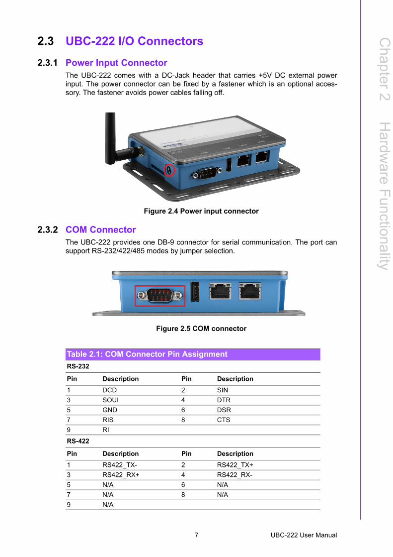
2.3.1 Power Input ConnectorThe UBC-222 comes with a DC-Jack header that carries +5V DC external powerinput. The power connector can be fixed by a fastener which is an optional acces-sory. The fastener avoids power cables falling off.
Figure 2.4 Power input connector
2.3.2 COM ConnectorThe UBC-222 provides one DB-9 connector for serial communication. The port cansupport RS-232/422/485 modes by jumper selection.
Figure 2.5 COM connector
Table 2.1: COM Connector Pin Assignment
RS-232
Pin Description Pin Description
1 DCD 2 SIN
3 SOUI 4 DTR
5 GND 6 DSR
7 RIS 8 CTS
9 RI
RS-422
Pin Description Pin Description
1 RS422_TX- 2 RS422_TX+
3 RS422_RX+ 4 RS422_RX-
5 N/A 6 N/A
7 N/A 8 N/A
9 N/A
7 UBC-222 User Manual
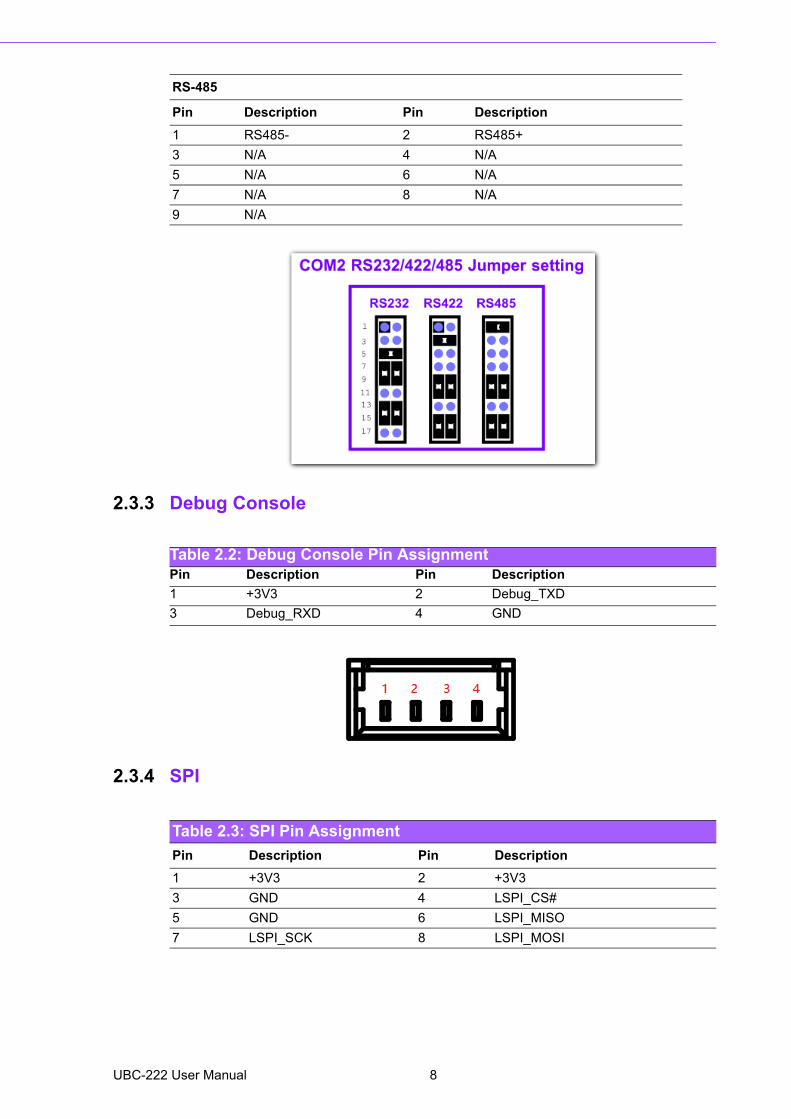
2.3.3 Debug Console
2.3.4 SPI
RS-485
Pin Description Pin Description
1 RS485- 2 RS485+
3 N/A 4 N/A
5 N/A 6 N/A
7 N/A 8 N/A
9 N/A
Table 2.2: Debug Console Pin AssignmentPin Description Pin Description
1 +3V3 2 Debug_TXD
3 Debug_RXD 4 GND
Table 2.3: SPI Pin Assignment
Pin Description Pin Description
1 +3V3 2 +3V3
3 GND 4 LSPI_CS#
5 GND 6 LSPI_MISO
7 LSPI_SCK 8 LSPI_MOSI
UBC-222 User Manual 8
Chapter 2
Hardw
areF
unctionality
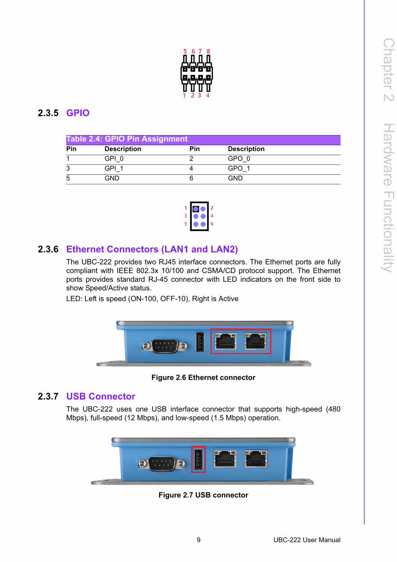
2.3.5 GPIO
2.3.6 Ethernet Connectors (LAN1 and LAN2)The UBC-222 provides two RJ45 interface connectors. The Ethernet ports are fullycompliant with IEEE 802.3x 10/100 and CSMA/CD protocol support. The Ethernetports provides standard RJ-45 connector with LED indicators on the front side toshow Speed/Active status.
LED: Left is speed (ON-100, OFF-10), Right is Active
Figure 2.6 Ethernet connector
2.3.7 USB ConnectorThe UBC-222 uses one USB interface connector that supports high-speed (480Mbps), full-speed (12 Mbps), and low-speed (1.5 Mbps) operation.
Figure 2.7 USB connector
Table 2.4: GPIO Pin AssignmentPin Description Pin Description
1 GPI_0 2 GPO_0
3 GPI_1 4 GPO_1
5 GND 6 GND
9 UBC-222 User Manual
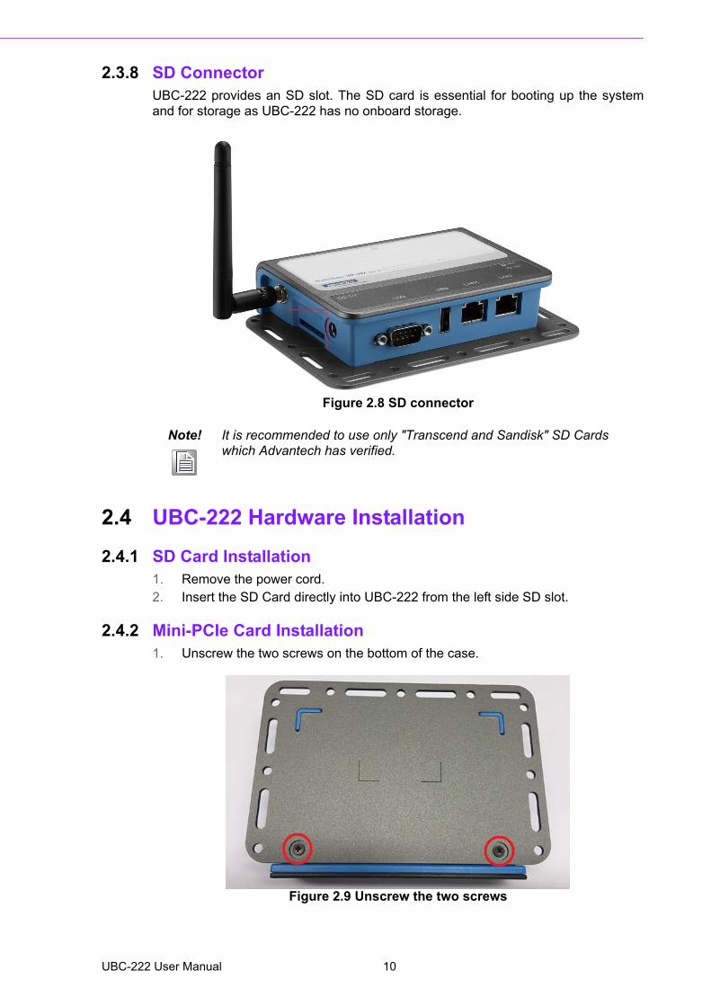
2.3.8 SD ConnectorUBC-222 provides an SD slot. The SD card is essential for booting up the systemand for storage as UBC-222 has no onboard storage.
Figure 2.8 SD connector
2.4 UBC-222 Hardware Installation
2.4.1 SD Card Installation 1. Remove the power cord.2. Insert the SD Card directly into UBC-222 from the left side SD slot.
2.4.2 Mini-PCIe Card Installation1. Unscrew the two screws on the bottom of the case.
Figure 2.9 Unscrew the two screws
Note! It is recommended to use only "Transcend and Sandisk" SD Cards which Advantech has verified.
UBC-222 User Manual 10
Chapter 2
Hardw
areF
unctionality
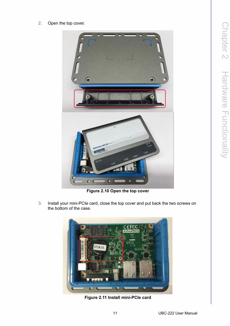
2. Open the top cover.
Figure 2.10 Open the top cover
3. Install your mini-PCIe card, close the top cover and put back the two screws on the bottom of the case.
Figure 2.11 Install mini-PCIe card
11 UBC-222 User Manual
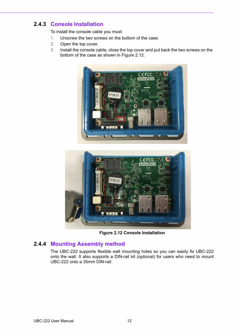
2.4.3 Console InstallationTo install the console cable you must:
1. Unscrew the two screws on the bottom of the case.2. Open the top cover. 3. Install the console cable, close the top cover and put back the two screws on the
bottom of the case as shown in Figure 2.12.
Figure 2.12 Console Installation
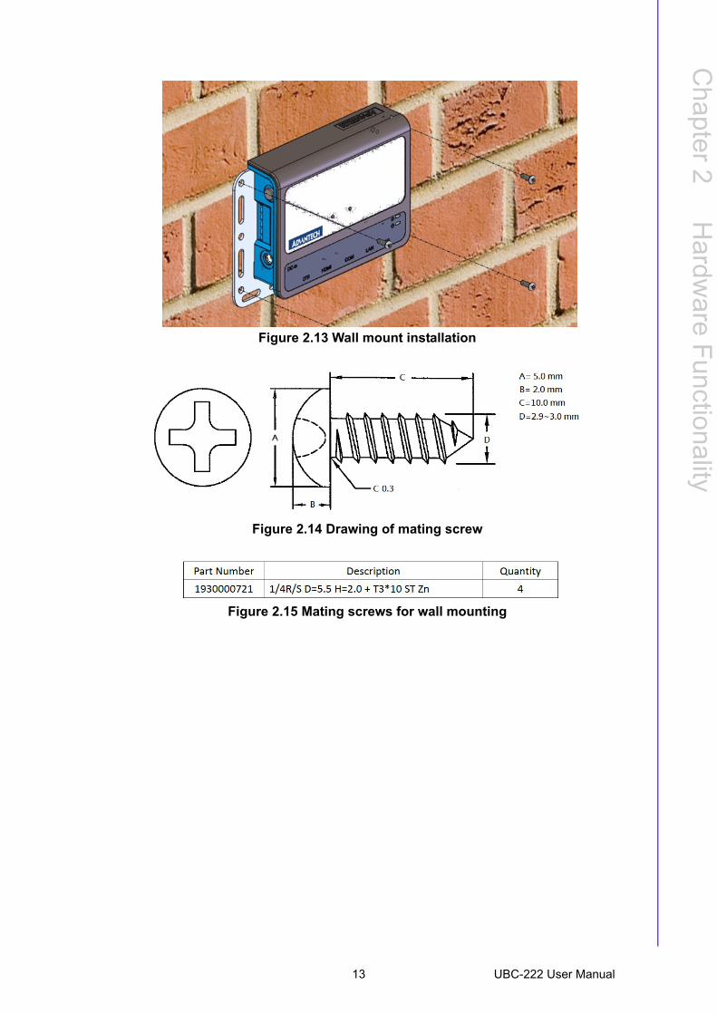
2.4.4 Mounting Assembly methodThe UBC-222 supports flexible wall mounting holes so you can easily fix UBC-222onto the wall. It also supports a DIN-rail kit (optional) for users who need to mountUBC-222 onto a 35mm DIN-rail.
UBC-222 User Manual 12
Chapter 2
Hardw
areF
unctionality
Figure 2.13 Wall mount installation
Figure 2.14 Drawing of mating screw
Figure 2.15 Mating screws for wall mounting
13 UBC-222 User Manual

UBC-222 User Manual 14
Chapter 3
3 Software FunctionalityThis chapter details the software operating on UBC-222.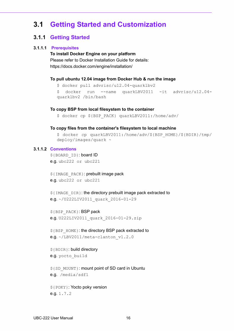
3.1 Getting Started and Customization
3.1.1 Getting Started
3.1.1.1 PrerequisitesTo install Docker Engine on your platform
Please refer to Docker Installation Guide for details:
https://docs.docker.com/engine/installation/
To pull ubuntu 12.04 image from Docker Hub & run the image
$ docker pull advrisc/u12.04-quarklbv2
$ docker run --name quarkLBV2011 -it advrisc/u12.04-quarklbv2 /bin/bash
To copy BSP from local filesystem to the container
$ docker cp ${BSP_PACK} quarkLBV2011:/home/adv/
To copy files from the container's filesystem to local machine
$ docker cp quarkLBV2011:/home/adv/${BSP_HOME}/${BDIR}/tmp/deploy/images/quark ~
3.1.1.2 Conventions${BOARD_ID}: board ID
e.g. ubc222 or ubc221
${IMAGE_PACK}: prebuilt image pack
e.g. ubc222 or ubc221
${IMAGE_DIR}: the directory prebuilt image pack extracted to
e.g. ~/U222LIV2011_quark_2016-01-29
${BSP_PACK}: BSP pack
e.g. U222LIV2011_quark_2016-01-29.zip
${BSP_HOME}: the directory BSP pack extracted to
e.g. ~/LBV2011/meta-clanton_v1.2.0
${BDIR}: build directory
e.g. yocto_build
${SD_MOUNT}: mount point of SD card in Ubuntu
e.g. /media/sdf1
${POKY}: Yocto poky version
e.g. 1.7.2
UBC-222 User Manual 16

Chapter 3
Softw
areF
unctionality
debug console / serial console
serial terminal program (e.g. minicom, putty, teraterm ...) that serial port is con-figured to 115200 8N1 terminal console
terminal console
terminal program (e.g. gnome-terminal, xfce4-terminal ...)
3.1.1.3 Introducing the BSPThe BSP is based on Yocto Project with Intel enhanced features for Quark, plus spe-cific target board features from Advantech Inc.
Naming Rule
The BSP/prebuilt image pack name is consist of the model name followed by "LB" or"LI" plus version number and released date.
For example, U222LIV2011_quark_2016-01-29.zip which "U221" stands for UBC-222, "LB" is acronym of Yocto Linux BSP, "V2011" stands for Version 2.011.
For example, U222LIV2011_quark_2016-01-29.zip which "LI" is acronym for prebuiltLinux Image.
BSP pack
Unpack BSP pack to home directory by performing the following command:
$ unzip ${BSP_PACK} -d ~/
The description of some important folders list below:
sources/
meta-advantech/: meta layer by Advantech
meta-intel/: meta layer by Intel
meta-clanton-*/: meta layer by Intel
setup.sh: to create one new build environment
Prebuilt image pack
Perform the following command to unpack prebuilt-image-pack to home directory.
$ unzip ${PREBUILT_IMAGE_PACK} -d ~/
Prepare one FAT32 formatted SD card, and mount it to mount point.
$ cp -a ${PREBUILT_IMAGE_DIR}/sdcard/* ${SD_MOUNT}/
3.1.1.4 Build InstructionsTo create a new build environment
Perform the following commands in terminal console
$ cd ${BSP_HOME}
$ ./setup.sh
$ BOARD=${BOARD_ID} source ./oe-init-build-env ${BDIR}
To continue an existing build environment
Perform the following commands in terminal console
17 UBC-222 User Manual

$ cd ${BSP_HOME}
$ BOARD=${BOARD_ID} source ./oe-init-build-env
To build all image files
1. To create/continue a build environment\2. Perform the following commands in the terminal console
$ bitbake image-full
3. The following files will be located in directory"./tmp/deploy/images/quark" while building process finished successfully. boot/grub/grub.conf
bzImage
core-image-minimal-initramfs-quark.cpio.gz
grub.efi
image-full-quark.ext3
To build a toolchain installer
1. To create/continue a build environment2. Perform the following command in the terminal console
$ bitbake image-full -c populate_sdk
3. The installer, iot-devkit-glibc-x86_64-image-full-i586-toolchain-${POKY}.sh, will be located in the directory "./tmp/deploy/sdk".
To build grub individually
1. To create/continue a build environment2. Perform the following command in the terminal console
$ bitbake grub
3. The file, grub.efi, will be located in directory, ./tmp/deploy/images/quark.
To build linux kernel individually
1. To create/continue a build environment2. Perform the following command in the terminal console
A.to show up menuconfig
$ bitbake linux-yocto-quark -c menuconfig
B.to do build
$ bitbake linux-yocto-quark
3. The file, bzImage, will be located in directory, ./tmp/deploy/images/quark.
To build initramfs individually
1. To create/continue a build environment2. Perform the following command in terminal console
$ bitbake core-image-minimal-initramfs
3. The file, core-image-minimal-initramfs-quark.cpio.gz, will be located in directory, ./tmp/deploy/images/quark.
UBC-222 User Manual 18

Chapter 3
Softw
areF
unctionality
3.1.2 Debug Port SettingUBC-222 can communicate with a host server (Windows or Linux) by using serialcables. Common serial communication programs such as HyperTerminal, Tera Termor PuTTY can be used in this case. The example as below describes the serial termi-nal setup using HyperTerminal on a Windows host:
1. Connect UBC-222 with your Windows PC by using a debug cable. (optional accessory, 1700021565-01)
2. Open HyperTerminal on your Windows PC, and select the settings as shown in Figure 3.1.
Figure 3.1 Debug port setting
3. After the bootloader is programmed into the SD card, power on UBC-222 by inserting the power adapter cord. The bootloader prompt will be displayed on the terminal screen.
3.1.3 Customization
3.1.3.1 Setting up SDK1. Please follow the steps below to build a toolchain installer.2. Perform the following command in the terminal console:
$ cd ${BSP_HOME}/${BDIR}/tmp/deploy/sdk
$ sudo ./clanton-tiny-uclibc-x86_64-i586-toolchain-${POKY}.sh
3. Enter directory or press Enter when the following question appears:
19 UBC-222 User Manual
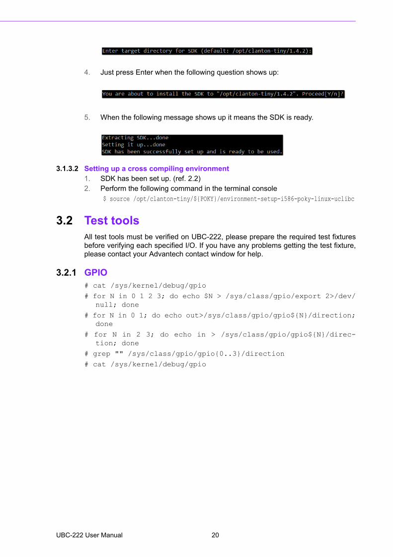
4. Just press Enter when the following question shows up:
5. When the following message shows up it means the SDK is ready.
3.1.3.2 Setting up a cross compiling environment1. SDK has been set up. (ref. 2.2)2. Perform the following command in the terminal console
$ source /opt/clanton-tiny/${POKY}/environment-setup-i586-poky-linux-uclibc
3.2 Test toolsAll test tools must be verified on UBC-222, please prepare the required test fixturesbefore verifying each specified I/O. If you have any problems getting the test fixture,please contact your Advantech contact window for help.
3.2.1 GPIO# cat /sys/kernel/debug/gpio
# for N in 0 1 2 3; do echo $N > /sys/class/gpio/export 2>/dev/null; done
# for N in 0 1; do echo out>/sys/class/gpio/gpio${N}/direction;done
# for N in 2 3; do echo in > /sys/class/gpio/gpio${N}/direc-tion; done
# grep "" /sys/class/gpio/gpio{0..3}/direction
# cat /sys/kernel/debug/gpio
UBC-222 User Manual 20

Chapter 3
Softw
areF
unctionality
3.2.1.1 Connecting #0 and #3cd /sys/class/gpio; \
echo 0 > gpio0/value; grep "" gpio{0,3}/value; \
echo 1 > gpio0/value; grep "" gpio{0,3}/value; cd -
3.2.1.2 Connecting #1 and #2cd /sys/class/gpio; \
echo 0 > gpio1/value; grep "" gpio{1,2}/value; \
echo 1 > gpio1/value; grep "" gpio{1,2}/value; cd -
21 UBC-222 User Manual
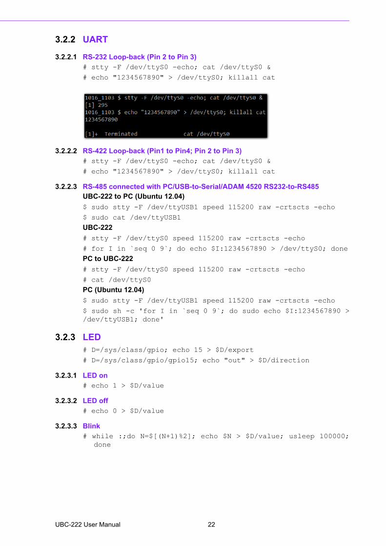
3.2.2 UART
3.2.2.1 RS-232 Loop-back (Pin 2 to Pin 3)# stty -F /dev/ttyS0 -echo; cat /dev/ttyS0 &
# echo "1234567890" > /dev/ttyS0; killall cat
3.2.2.2 RS-422 Loop-back (Pin1 to Pin4; Pin 2 to Pin 3)# stty -F /dev/ttyS0 -echo; cat /dev/ttyS0 &
# echo "1234567890" > /dev/ttyS0; killall cat
3.2.2.3 RS-485 connected with PC/USB-to-Serial/ADAM 4520 RS232-to-RS485UBC-222 to PC (Ubuntu 12.04)
$ sudo stty -F /dev/ttyUSB1 speed 115200 raw -crtscts -echo
$ sudo cat /dev/ttyUSB1
UBC-222
# stty -F /dev/ttyS0 speed 115200 raw -crtscts -echo
# for I in `seq 0 9`; do echo $I:1234567890 > /dev/ttyS0; done
PC to UBC-222
# stty -F /dev/ttyS0 speed 115200 raw -crtscts -echo
# cat /dev/ttyS0
PC (Ubuntu 12.04)
$ sudo stty -F /dev/ttyUSB1 speed 115200 raw -crtscts -echo
$ sudo sh -c 'for I in `seq 0 9`; do sudo echo $I:1234567890 >/dev/ttyUSB1; done'
3.2.3 LED# D=/sys/class/gpio; echo 15 > $D/export
# D=/sys/class/gpio/gpio15; echo "out" > $D/direction
3.2.3.1 LED on# echo 1 > $D/value
3.2.3.2 LED off# echo 0 > $D/value
3.2.3.3 Blink# while :;do N=$[(N+1)%2]; echo $N > $D/value; usleep 100000;
done
UBC-222 User Manual 22

Chapter 3
Softw
areF
unctionality
3.2.4 WifiUsing Intel wifi card for example:
Intel Centrino Wireless-N 135
Model:135BNHMW
Set wifi ssid to environment variable, SSID.
Set wifi password to environment variable, PSWD.
# SSID={ssid here}
# PSWD= {password here}
# wifi_connect.sh "${SSID}" "${PSWD}"
# DEV=wlan0
# SVC=$(P=`connmanctl services | grep "$SSID"` && echo -nwifi_${P#*wifi_})
# set - `connmanctl services $SVC | grep "Nameservers ="`
# DNS=${4/,/}
# ping -c5 $DNS -I $DEV
23 UBC-222 User Manual

3.2.5 LANMake sure the DHCP service works in the connected LAN.
Remove network connection from both of the two LAN ports.
# DEV=eth0 # or eth1
# MAC=$(set - `ifconfig $DEV | grep HWaddr`; echo ${5~~} | sed"s/://g")
# set - $(connmanctl services | grep $MAC)
# SVC=$3
# set - `connmanctl services $SVC | grep "Nameservers ="`
# DNS=${4/,/}
# ping -c5 $DNS -I $DEV
3.2.6 USB# dd if=/dev/urandom of=/PTN bs=1024 count=1
# dd if=/PTN of=/dev/sda bs=1024 count=1 seek=4
# dd if=/dev/sda of=/READ bs=1024 count=1 skip=4
# diff /READ /PTN && echo "correct" || echo "incorrect"
UBC-222 User Manual 24
Chapter 3
Softw
areF
unctionality
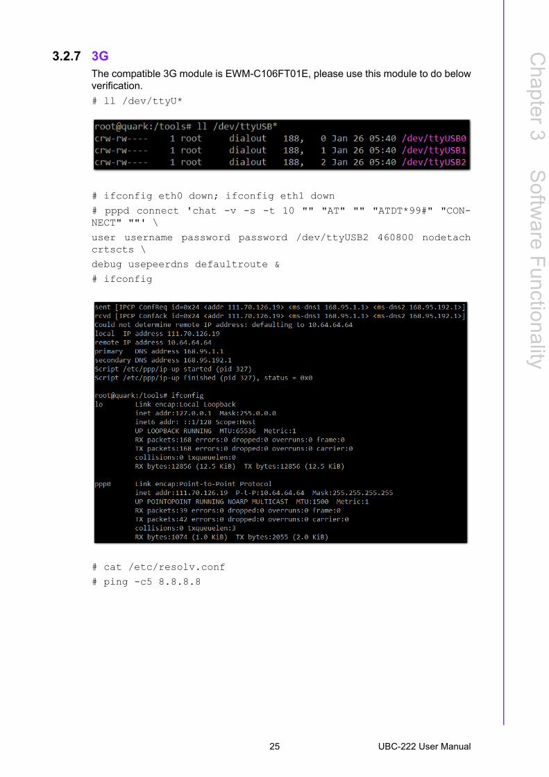
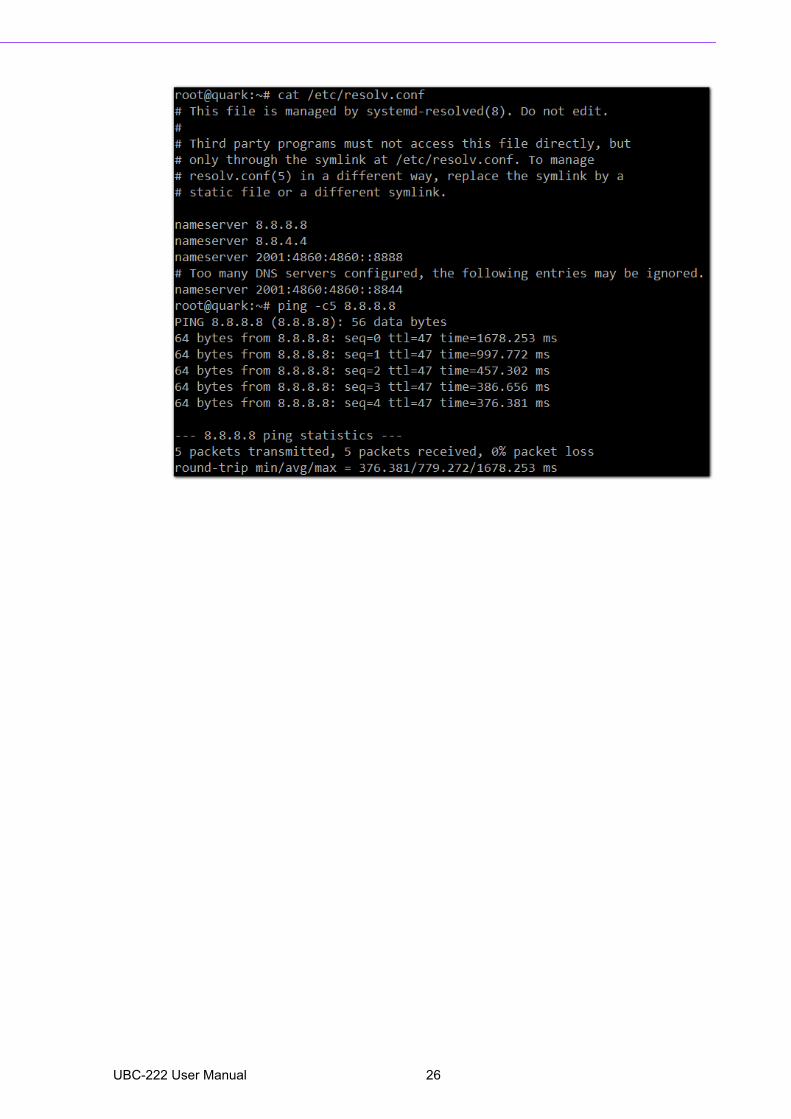
3.2.7 3GThe compatible 3G module is EWM-C106FT01E, please use this module to do belowverification.
# ll /dev/ttyU*
# ifconfig eth0 down; ifconfig eth1 down
# pppd connect 'chat -v -s -t 10 "" "AT" "" "ATDT*99#" "CON-NECT" ""' \
user username password password /dev/ttyUSB2 460800 nodetachcrtscts \
debug usepeerdns defaultroute &
# ifconfig
# cat /etc/resolv.conf
# ping -c5 8.8.8.8
25 UBC-222 User Manual
UBC-222 User Manual 26
Chapter 4
4 Advantech ServicesThis chapter introduces Advan-tech design in serviceability, tech-nical support and warranty policy.
4.1 Contact InformationBelow is the contact information for Advantech customer service.
You can also reach our service team through the below website, our technical sup-port engineer will provide quick response once the form is filled out:
http://www.advantech.com.tw/contact/default.aspx?page=contact_form2&sub-ject=Technical+Support
4.2 Technical Support and AssistanceFor more information about this and other Advantech products, please visit our web-site at:
<http://www.advantech.com/>
<http://www.advantech.com/ePlatform/>
For technical support and service, please visit our support website at:
<http://support.advantech.com.tw/support/>
1. Visit the Advantech web site at www.advantech.com/support where you can find the latest information about the product.
2. Contact your distributor, sales representative, or Advantech's customer Service center for technical support if you need additional assistance. Please have the following information ready before you call:– Product name and serial number– Description of your peripheral attachments– Description of your software (operating system, version, application software,
etc.)– A complete description of the problem– The exact wording of any error messages
Region/Country Contact Information
America 1-888-576-9688
Brazil 0800-770-5355
Mexico 01-800-467-2415
Europe (Toll Free) 00800-2426-8080
Singapore & SAP 65-64421000
Malaysia 1800-88-1809
Australia (Toll Free) 1300-308-531
China (Toll Free)[email protected]
India (Toll Free) 1-800-425-5071
Japan (Toll Free) 0800-500-1055
Korea (Toll Free)080-363-9494080-363-9495
Taiwan (Toll Free) 0800-777-111
Russia (Toll Free) 8-800-555-01-50
UBC-222 User Manual 28
Chapter 4
Advantech
Services
4.3 Global Service Policy
4.3.1 Warranty PolicyBelow is the warranty policy of Advantech products:
4.3.2 Warranty PeriodAdvantech branded off-the-shelf products and 3rd party off-the-shelf products used toassemble Advantech Configure to Order products are entitled to a 2 years completeand prompt global warranty service. Product defects in design, materials, and work-manship, are covered from the date of shipment.
All customized products will by default carry a 15 months regional warranty service.The actual product warranty terms and conditions may vary based on sales contract.
All 3rd party products purchased separately will be covered by the original manufac-turer's warranty and time period, and shall not exceed one year of coverage throughAdvantech.
4.3.3 Repairs under WarrantyIt is possible to obtain a replacement (Cross-Shipment) during the first 30 days of thepurchase, through your original ADVANTECH supplier to arrange DOA replacementif the products were purchased directly from ADVANTECH and the product is DOA(Dead-on-Arrival). The DOA Cross-Shipment excludes any shipping damage, cus-tomized and/or build-to-order products.
For those products which are not DOA, the return fee to an authorized ADVANTECHrepair facility will be at the customers' expense. The shipping fee for reconstructiveproducts from ADVANTECH back to customers' sites will be at ADVANTECH'sexpense.
4.3.4 Exclusions from WarrantyThe product is excluded from warranty if:
The product has been found to be defective after expiry of the warranty period. Warranty has been voided by removal or alternation of product or part identifi-
cation labels. The product has been misused, abused, or subjected to unauthorized disas-
sembly/modification; placed in an unsuitable physical or operating environment; improperly maintained by the customer; or failure caused which ADVANTECH is not responsible for, whether by accident or other cause. Such conditions will be determined by ADVANTECH at its sole unfettered discretion.
The product is damaged beyond repair due to a natural disaster such as a light-ing strike, flood, earthquake, etc.
Product updates/upgrades and tests upon the request of customers who are without warranty.
29 UBC-222 User Manual
4.4 Repair Process
4.4.1 Obtaining an RMA NumberAll returns from customers must be authorized with an ADVANTECH RMA (ReturnMerchandise Authorization) number. Any returns of defective units or parts withoutvalid RMA numbers will not be accepted; they will be returned to the customer at thecustomer's cost without prior notice.
An RMA number is only an authorization for returning a product; it is not an approvalfor repair or replacement. When requesting an RMA number, please access ADVAN-TECH's RMA web site: http://erma.ADVANTECH.com.tw with an authorized user IDand password.
You must fill out basic product and customer information and describe the problemsencountered in detail in "Problem Description". Vague entries such as "does notwork" and "failure" are not very helpful.
If you are uncertain about the cause of the problem, please contact ADVANTECH'sApplication Engineers (AE). They may be able to find a solution that does not requiresending the product for repair.
The serial number of the whole set is required if only a key defective part is returnedfor repair. Otherwise, the case will be regarded as out-of-warranty.
4.4.2 Returning the Product for RepairIt's possible customers can save time and meet end-user requirements by returningdefective products to an authorized ADVANTECH repair facility without an extracross-region charge. It is required to contact the local repair center before offeringglobal repair service.
It is recommended to send cards without accessories (manuals, cables, etc.).Remove any unnecessary components from the card, such as CPU, DRAM and CFCard. If you send all these parts back (because you believe they may be part of theproblem), please note clearly that they are included. Otherwise, ADVANTECH is notresponsible for any items not listed. Make sure the "Problem Description" isenclosed.
European Customers that are located outside European Community are requested touse UPS as the forwarding company. We strongly recommend adding a packing listto all shipments. Please prepare a shipment invoice according to the following guide-lines to decrease goods clearance time:
1. Give a low value to the product on the invoice, or additional charges will be lev-ied by customs that will be borne by the sender.
2. Add information "Invoice for customs purposes only with no commercial value" on the shipment invoice.
3. Show RMA numbers, product serial numbers and warranty status on the ship-ment invoice.
4. Add information about country of origin of goodsIn addition, please attach an invoice with RMA number to the carton, then write theRMA number on the outside of the carton and attach the packing slip to save han-dling time. Please also address the parts directly to the Service Department and markthe package "Attn. RMA Service Department".
UBC-222 User Manual 30
Chapter 4
Advantech
Services
All products must be returned in properly packed ESD material or anti-static bags.ADVANTECH reserves the right to return unrepaired items at the customer's cost ifinappropriately packed.
Door-to-Door transportation such as speed post is recommended for delivery, other-wise, the sender should bear additional charges such as clearance fees if Air-Cargois adopted.
Should DOA cases fail, ADVANTECH will take full responsibility for the product andtransportation charges. If the items are not DOA, but fail within warranty, the senderwill bear the freight charges. For out-of-warranty cases, customers must cover thecost and take care of both outward and inward transportation.
4.4.3 Service Charges The product is excluded from warranty if:
The product is repaired after expiry of the warranty period. The product is tested or calibrated after expiry of the warranty period, and a No
Problem Found (NPF) result is obtained. The product, though repaired within the warranty period, has been misused,
abused, or subjected to unauthorized disassembly/modification; placed in an unsuitable physical or operating environment; improperly maintained by the cus-tomer; or failure caused which ADVANTECH is not responsible whether by acci-dent or other cause. Such conditions will be determined by ADVANTECH at its sole unfettered discretion.
The product is damaged beyond repair due to a natural disaster such as a light-ing strike, flood, earthquake, etc.
Product updates and tests upon the request of customers who are without war-ranty.
If a product has been repaired by ADVANTECH, and within three months after such arepair the product requires another repair for the same problem, ADVANTECH will dothis repair free of charge. However, such free repairs do not apply to products whichhave been misused, abused, or subjected to unauthorized disassembly/modification;placed in an unsuitable physical or operating environment; improperly maintained bythe customer; or failure caused which ADVANTECH is not responsible whether byaccident or other cause.
Please contact your nearest regional service center for detail service quotation.
Before we start out-of-warranty repairs, we will send you a pro forma invoice (P/I)with the repair charges. When you remit the funds, please reference the P/I numberlisted under "Our Ref". ADVANTECH reserves the right to deny repair services tocustomers that do not return the DOA unit or sign the P/I. Meanwhile, ADVANTECHwill scrap defective products without prior notice if customers do not return the signedP/I within 3 months.
4.4.4 Repair ReportADVANTECH returns each product with a "Repair Report" which shows the result ofthe repair. A "Repair Analysis Report" is also provided to customers upon request. Ifthe defect is not caused by ADVANTECH design or manufacturing, customers will becharged US$60 or US$120 for in-warranty or out-of-warranty repair analysis reportsrespectively.
31 UBC-222 User Manual

4.4.5 Custody of Products Submitted for RepairADVANTECH will retain custody of a product submitted for repair for one month whileit is waiting for return of a signed P/I or payment (A/R). If the customer fails torespond within such period, ADVANTECH will close the case automatically. ADVAN-TECH will take reasonable measures to stay in proper contact with the customer dur-ing this one month period.
4.4.6 Shipping Back to the CustomerThe forwarding company for RMA returns from ADVANTECH to customers isselected by ADVANTECH. Per customer requirement, other express services can beadopted, such as UPS, FedEx and etc. The customer must bear the extra costs ofsuch alternative shipment. If you require any special arrangements, please indicatethis when shipping the product to us.
UBC-222 User Manual 32

Chapter 4
Advantech
Services
33 UBC-222 User Manual

www.advantech.comPlease verify specifications before quoting. This guide is intended for referencepurposes only.All product specifications are subject to change without notice.No part of this publication may be reproduced in any form or by any means,electronic, photocopying, recording or otherwise, without prior written permis-sion of the publisher.All brand and product names are trademarks or registered trademarks of theirrespective companies.© Advantech Co., Ltd. 2016


