68
QA-90 User Manual QA-90 Electrical Safety Analyzer P/N 11025 V.3.47-3

QA-90
User Manual
QA-90 Electrical Safety Analyzer
P/N 11025
V.3.47-3
ii
Copyright 2004 by METRON. All rights reserved.
METRON:
USA _ ____ FRANCE________ GERMANY NORWAY______
1345 Monroe NW 30, rue Paul Claudel Gundastrasse 29 Vegamot 8
Grand Rapids, MI 49505 91000 Evry, France D-63762 Grossostheim N-7048 Trondheim
Phone: (+1) 888 863-8766 Phone: (+33) 1 6078 8899 Phone: (+49) 6026 993975 Phone: (+47) 7395 4700
Fax: (+1) 616 454-3350 Fax: (+33) 1 6078 6839 Fax: (+49) 6026 977079 Fax: (+47) 7395 4701
E-mail: [email protected] E-mail: [email protected] E-mail:[email protected] E-mail: [email protected]
Disclaimer
METRON provides this publication as is without warranty of any kind, either express or implied, including but
not limited to the implied warranties of merchantability or fitness for any particular purpose. Further, METRON
reserves the right to revise this publication and to make changes from time to time to the content hereof, without
obligation to METRON or its local representatives to notify any person of such revision or changes. Some jurisdic-
tions do not allow disclaimers of expressed or implied warranties in certain transactions; therefore, this statement
may not apply to you.
Limited Warranty METRON warrants that the QA-90 Electrical Safety Analyzer will substantially conform to published specifi-
cations and to the documentation, provided that it is used for the purpose for which it was designed. METRON
will, for a period of twelve (12) months from date of purchase, replace or repair any defective analyzer, if the fault
is due to a manufacturing defect. In no event will METRON or its local representatives be liable for direct, indirect,
special, incidental, or consequential damages arising out of the use of or inability to use the QA-90 Electrical Safe-
ty Analyzer, even if advised of the possibility of such damages. METRON or its local representatives are not re-
sponsible for any costs, loss of profits, loss of data, or claims by third parties due to use of, or inability to use the
QA-90 Electrical Safety Analyzer. Neither METRON nor its local representatives will accept, nor be bound by any
other form of guarantee concerning the QA-90 Electrical Safety Analyzer other than this guarantee. Some jurisdic-
tions do not allow disclaimers of expressed or implied warranties in certain transactions; therefore, this statement
may not apply to you.
iii
Table of Contents
MANUAL REVISION RECORD ......................................................................................................... V
1. INTRODUCTION ................................................................................................................... 1-1
1.1 QA-90 Features ...................................................................................................................1-1 1.2 Specifications ......................................................................................................................1-1 1.3 General Information ............................................................................................................1-3
2. INSTALLATION ..................................................................................................................... 2-1
2.1 Receipt, Inspection and Return ...........................................................................................2-1 2.2 Setup ...................................................................................................................................2-2 2.3 Power ..................................................................................................................................2-2 2.4 Ansur & PRO-Soft ..............................................................................................................2-2
3. OPERATING QA-90 ............................................................................................................... 3-1
3.1 Control Switches and Connections .....................................................................................3-1 3.2 Key Pad Functions ..............................................................................................................3-3 3.3 Function of The Bar Code Reader ......................................................................................3-3 3.4 Menu and Function Keys ....................................................................................................3-4 3.5 Display Menus and Messages .............................................................................................3-4 3.6 Measurements with Several Modules in Manual Mode ......................................................3-9 3.7 Storing Setup Parameters in Flash Memory ......................................................................3-10 3.8 Upgrading the QA-90 Software Program ..........................................................................3-11 3.9 Cleaning the QA-90 ..........................................................................................................3-14
4. EXAMPLE TEST MEASUREMENTS ................................................................................. 4-1
4.1 Test Lead Calibration..........................................................................................................4-1 4.2 Connecting an Instrument without Patient Inputs ...............................................................4-2 4.3 Connecting an Instrument with Patient Inputs ....................................................................4-3 4.4 Power Cable Test ................................................................................................................4-5 4.5 Current Measurement Test (Dual Lead)..............................................................................4-6 4.6 Voltage Measurement Test (Dual Lead) .............................................................................4-8 4.7 Resistance Measurement (Dual Lead) ...............................................................................4-10 4.8 Connecting Auxiliary Power Source / Isolating Transformer ...........................................4-11
APPENDIX A: IEC 60601.1, UL 2601.1 AND VDE 0751 TESTING ................................................ 1
A.1 Classification of Equipment ................................................................................................... 1 A.2 Tests on Mains Powered Class 1 & 2 Equipment According To IEC 60601.1/UL 2601.1 ... 4 A.3 Tests on Internally Powered Equipment According To IEC 60601.1/UL 2601.1 ............... 13 A.4 System Tests Based on IEC 60601.1/UL 2601.1 ................................................................. 15 A.5 Tests According To VDE 0751:10-1990/2001 .................................................................... 16

iv
APPENDIX B: ERROR REPORT FORM, QA-90 ............................................................................. 1
APPENDIX C: SUGGESTION FORM, QA-90 ................................................................................... 1
v
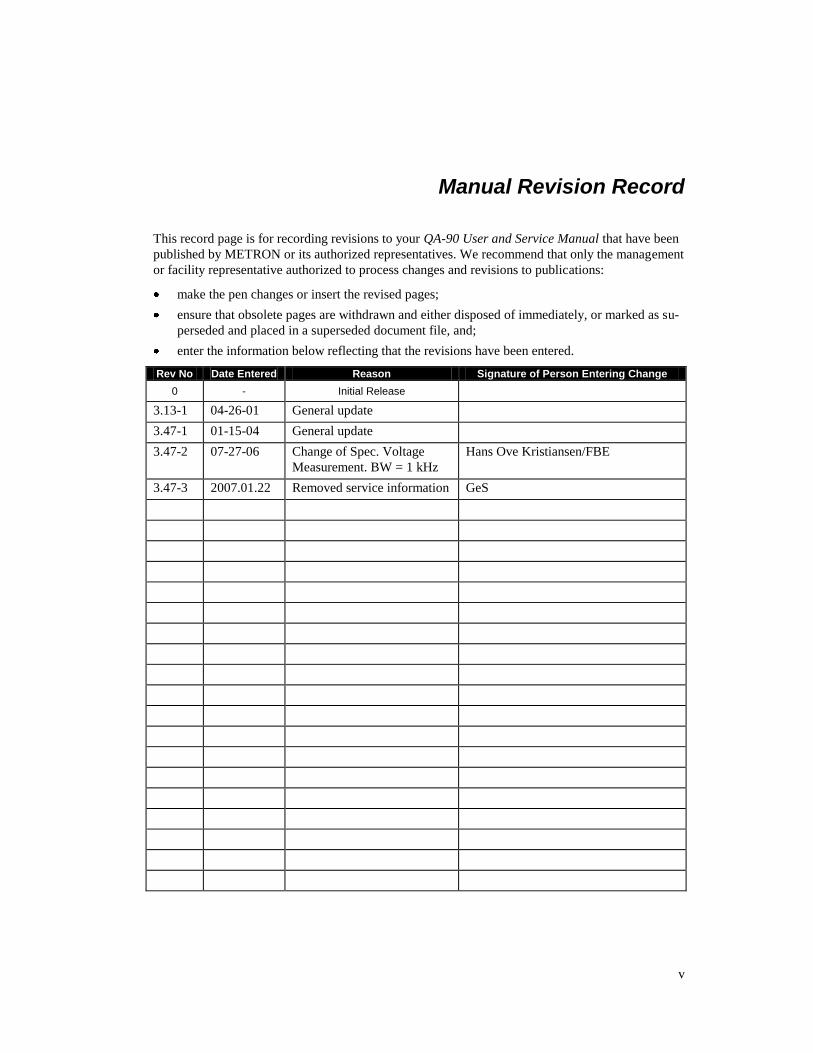
Manual Revision Record
This record page is for recording revisions to your QA-90 User and Service Manual that have been
published by METRON or its authorized representatives. We recommend that only the management
or facility representative authorized to process changes and revisions to publications:
make the pen changes or insert the revised pages;
ensure that obsolete pages are withdrawn and either disposed of immediately, or marked as su-
perseded and placed in a superseded document file, and;
enter the information below reflecting that the revisions have been entered.
Rev No Date Entered Reason Signature of Person Entering Change
0 - Initial Release
3.13-1 04-26-01 General update
3.47-1 01-15-04 General update
3.47-2 07-27-06 Change of Spec. Voltage
Measurement. BW = 1 kHz
Hans Ove Kristiansen/FBE
3.47-3 2007.01.22 Removed service information GeS
vi
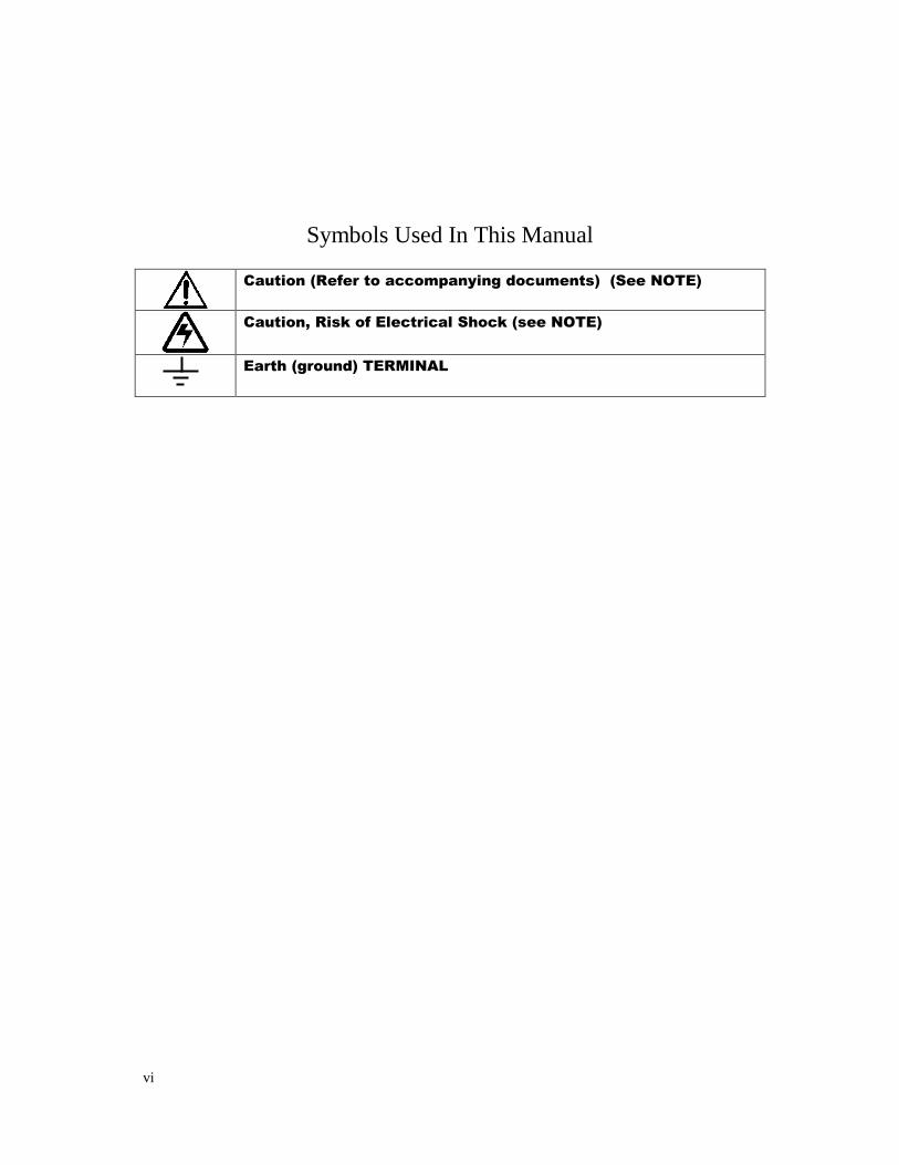
Symbols Used In This Manual
Caution (Refer to accompanying documents) (See NOTE)
Caution, Risk of Electrical Shock (see NOTE)
Earth (ground) TERMINAL
1-1
1. Introduction
This chapter describes the QA-90 Electrical Safety Tester’s features
and specifications.
1.1 QA-90 Features The QA-90 represents a new generation of safety testing equipment. It
is the only automatic safety analyzer that can test units with different
classes of protection in one test run (e.g., cardiac float and body float
defibrillators). It is simple to use. All you need do is select the type
and class of equipment to test. When you press START, QA-90 ex-
ecutes the tests prescribed to the selected standard.
Test results may be printed out immediately, or stored internally in the
unit for later use. QA-90 has full remote control, and may be operated
from PRO-Soft QA-90 software. PRO-Soft QA-90 enables you to
make your own test protocols, store the information on disk, and ex-
port formatted data to any other database or equipment management
program. Individual test sequences may be compiled to satisfy na-
tional and international standards.
The following standards may be compiled either fully or in part:
IEC 60601.1, UL 2601.1, IEC 60601.1.1, UL 2601.1.1, IEC
60601.2.4, IEC 61010-1, EN 60601-1, VDE 0750 Tl/12-91, BS 5724,
CAN/CSA-C22.2 No 601.1-M90, AS 3200.1, NZS 6150:1990, VDE
0751-1:10-1990, VDE 0751-1:10-2001, ÖVE 0751, UL 544, HEI 95,
HEI 158 among others.
1.2 Specifications 1. Voltage Measurement
Measurements may be obtained in the following ways:
Between leads 1 and 2 (in the power contact).
Between lead 1 and ground (in the power contact).
Between lead 2 and ground (in the power contact).
Between input/output E+ and E- (floating inputs/outputs).
Range 0 - 400V true RMS. Resolution 0.1V Accuracy DC - 100 Hz, 1% of full scale +1 LSD
100 Hz-1 kHz, 2% of scale +1 LSD No. of Tests 4 or multiple (LSD = least significant digit)
1-2
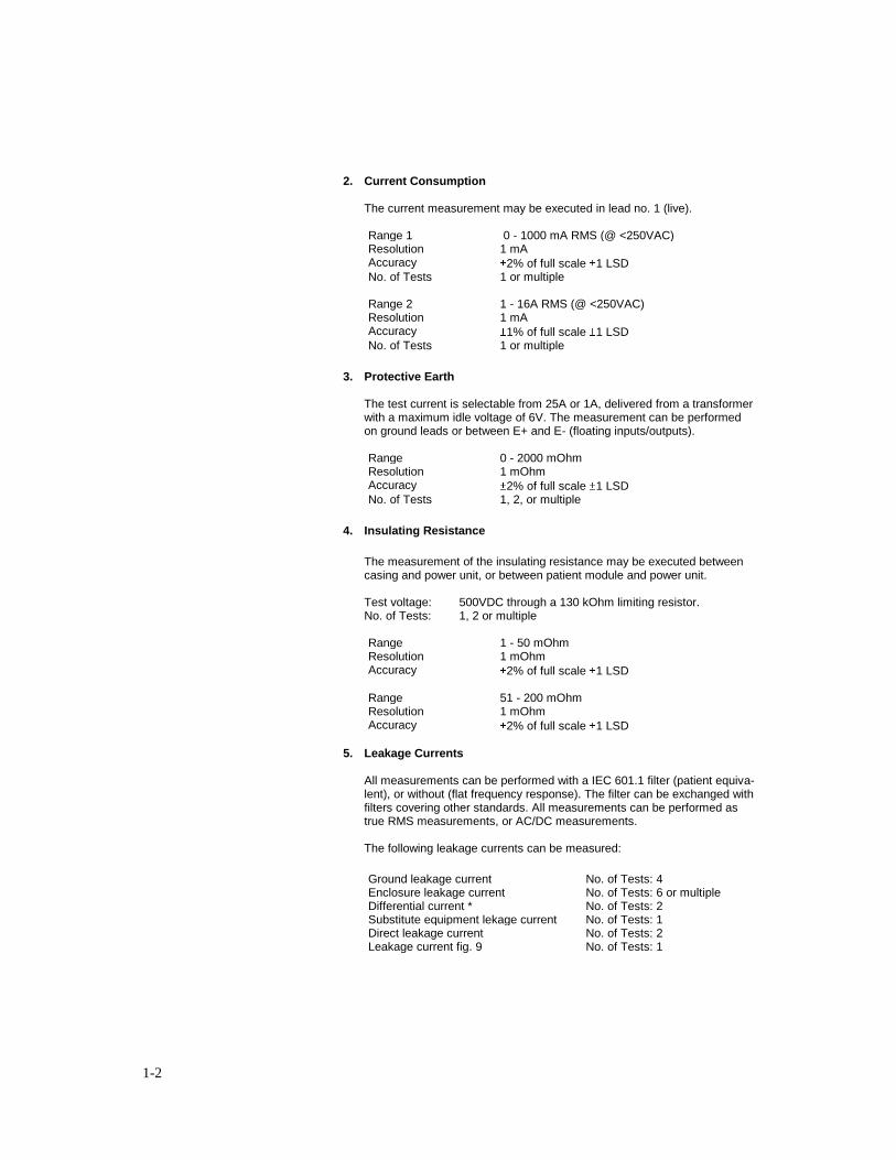
2. Current Consumption
The current measurement may be executed in lead no. 1 (live).
Range 1 0 - 1000 mA RMS (@ <250VAC) Resolution 1 mA Accuracy 2% of full scale 1 LSD No. of Tests 1 or multiple
Range 2 1 - 16A RMS (@ <250VAC) Resolution 1 mA Accuracy 1% of full scale 1 LSD No. of Tests 1 or multiple
3. Protective Earth
The test current is selectable from 25A or 1A, delivered from a transformer with a maximum idle voltage of 6V. The measurement can be performed on ground leads or between E+ and E- (floating inputs/outputs).
Range 0 - 2000 mOhm Resolution 1 mOhm Accuracy 2% of full scale 1 LSD No. of Tests 1, 2, or multiple
4. Insulating Resistance
The measurement of the insulating resistance may be executed between casing and power unit, or between patient module and power unit. Test voltage: 500VDC through a 130 kOhm limiting resistor. No. of Tests: 1, 2 or multiple
Range 1 - 50 mOhm Resolution 1 mOhm Accuracy 2% of full scale 1 LSD
Range 51 - 200 mOhm Resolution 1 mOhm Accuracy 2% of full scale 1 LSD
5. Leakage Currents
All measurements can be performed with a IEC 601.1 filter (patient equiva-lent), or without (flat frequency response). The filter can be exchanged with filters covering other standards. All measurements can be performed as true RMS measurements, or AC/DC measurements. The following leakage currents can be measured:
Ground leakage current No. of Tests: 4 Enclosure leakage current No. of Tests: 6 or multiple Differential current * No. of Tests: 2 Substitute equipment lekage current No. of Tests: 1 Direct leakage current No. of Tests: 2 Leakage current fig. 9 No. of Tests: 1
1-3
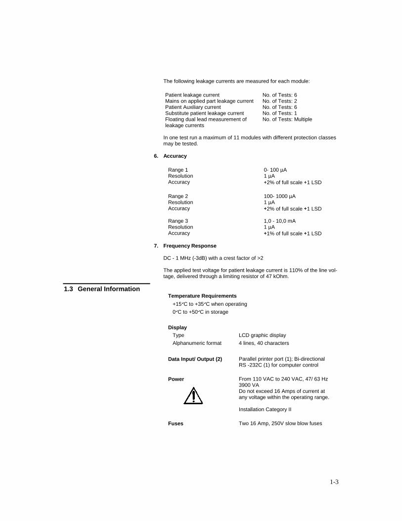
The following leakage currents are measured for each module:
Patient leakage current No. of Tests: 6 Mains on applied part leakage current No. of Tests: 2 Patient Auxiliary current No. of Tests: 6 Substitute patient leakage current No. of Tests: 1 Floating dual lead measurement of leakage currents
No. of Tests: Multiple
In one test run a maximum of 11 modules with different protection classes may be tested.
6. Accuracy
Range 1 0- 100 µA Resolution 1 µA Accuracy 2% of full scale 1 LSD
Range 2 100- 1000 µA Resolution 1 µA Accuracy 2% of full scale 1 LSD
Range 3 1,0 - 10,0 mA Resolution 1 µA Accuracy 1% of full scale 1 LSD
7. Frequency Response DC - 1 MHz (-3dB) with a crest factor of >2
The applied test voltage for patient leakage current is 110% of the line vol-tage, delivered through a limiting resistor of 47 kOhm.
1.3 General Information Temperature Requirements
+15 C to +35 C when operating
0 C to +50 C in storage
Display
Type LCD graphic display
Alphanumeric format 4 lines, 40 characters
Data Input/ Output (2) Parallel printer port (1); Bi-directional RS -232C (1) for computer control
Power From 110 VAC to 240 VAC, 47/ 63 Hz 3900 VA Do not exceed 16 Amps of current at any voltage within the operating range. Installation Category II
Fuses Two 16 Amp, 250V slow blow fuses
1-4
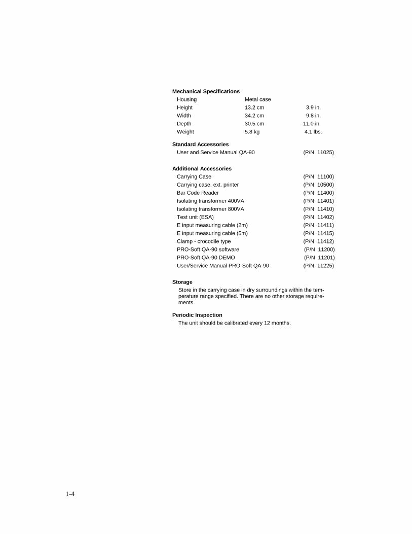
Mechanical Specifications
Housing Metal case
Height 13.2 cm 3.9 in.
Width 34.2 cm 9.8 in.
Depth 30.5 cm 11.0 in.
Weight 5.8 kg 4.1 lbs.
Standard Accessories
User and Service Manual QA-90 (P/N 11025)
Additional Accessories
Carrying Case (P/N 11100)
Carrying case, ext. printer (P/N 10500)
Bar Code Reader (P/N 11400)
Isolating transformer 400VA (P/N 11401)
Isolating transformer 800VA (P/N 11410)
Test unit (ESA) (P/N 11402)
E input measuring cable (2m) (P/N 11411)
E input measuring cable (5m) (P/N 11415)
Clamp - crocodile type (P/N 11412)
PRO-Soft QA-90 software (P/N 11200)
PRO-Soft QA-90 DEMO (P/N 11201)
User/Service Manual PRO-Soft QA-90 (P/N 11225)
Storage
Store in the carrying case in dry surroundings within the tem-perature range specified. There are no other storage require-ments.
Periodic Inspection
The unit should be calibrated every 12 months.
2-1
2. Installation
This chapter explains unpacking, receipt inspection and claims, and
the general procedures for initial QA-90 setup. Example test setup
procedures are contained in Chapter 4, Example Test Measurements.
2.1 Receipt, Inspection
and Return 1. Inspect the outer box for damage.
2. Carefully unpack all items from the box and check to see that you
have the following items:
QA-90 Electrical Safety Tester (P.N. 11200)
QA-90 User and Service Manual (P.N. 11025)
3. If you note physical damage, or if the unit fails to function ac-
cording to specification, inform the supplier immediately. When
METRON AS or the company’s representative, is informed,
measures will be taken to either repair the unit or dispatch a re-
placement. The customer will not have to wait for a claim to be
investigated by the supplier. The customer should place a new
purchase order to ensure delivery.
4. When returning an instrument to METRON AS, or the company
representative, fill out the address label, describe what is wrong
with the instrument, and provide the model and serial numbers. If
possible, use the original packaging material for return shipping.
Otherwise, repack the unit using:
a reinforced cardboard box, strong enough to carry the
weight of the unit.
at least 5 cm of shock-absorbing material around the unit.
nonabrasive dust-free material for the other parts.
Repack the unit in a manner to ensure that it cannot shift in the
box during shipment.
METRON’s product warranty is on page ii of this manual. The war-
ranty does not cover freight charges. C.O.D. will not be accepted
without authorization from METRON A.S or its representative.
2-2
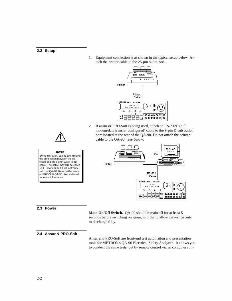
2.2 Setup
1. Equipment connection is as shown in the typical setup below. At-
tach the printer cable to the 25-pin outlet port.
2. If ansur or PRO-Soft is being used, attach an RS-232C (null
modem/data transfer configured) cable to the 9-pin D-sub outlet
port located at the rear of the QA-90. Do not attach the printer
cable to the QA-90. See below.
2.3 Power
Main On/Off Switch. QA-90 should remain off for at least 5
seconds before switching on again, in order to allow the test circuits
to discharge fully.
2.4 Ansur & PRO-Soft Ansur and PRO-Soft are front-end test automation and presentation
tools for METRON's QA-90 Electrical Safety Analyzer. It allows you
to conduct the same tests, but by remote control via an computer run-
NOTE
Some RS-232C cables are missing the connection between the se-venth and the eighth wires in the cable. The cable may still be called NULL-modem, but it will not work with the QA-90. Refer to the ansur or PRO-Soft QA-90 Users Manual for more information.
2-3
ning Windows 98, 2000 or XP. Additionally, the program has addi-
tional features to automate and enhance your electrical safety testing.
Each of the QA-90 tests can be run independently from ansur or PRO-
Soft in the “Manual” test mode. Results are shown on the PC screen
during testing, and the user is prompted to set the tested equipment
accordingly. At the conclusion of tests, the user may print a report,
store the test and results on disk, or both. Combinations of tests can
be created and stored as “Test Template.” The program maintains a
library of these templates. In this way you can store and retrieve
templates that are appropriate for each kind of equipment being tested
at your facility.
Templates can include checklists, written procedure, and equipment
data in the form of a test “Protocol.” The equipment data can be
entered manually into the protocol, or it may be retrieved by ansur or
PRO-Soft from a database program or other equipment files.
Protocols can be created easily for each item of equipment in your
inventory, and stored for use. Test protocols with results can be
printed, or stored on disk, and the results of testing can be sent back
to the equipment database to close a work order and update the
service history.
NOTE Ansur and PRO-Soft has its own user manual, which contains all the information concerning the program. If you order a demon-stration version of the program you also receive the manual.

2-4
This page intentionally left blank.
3-1
3. Operating QA-90
This chapter explains the operating controls, switches and menus of
the QA-90, details how to use them in testing, and provides general
information on printouts and operator maintenance.
3.1 Control Switches and
Connections
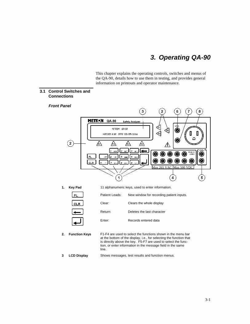
Front Panel
1. Key Pad 11 alphanumeric keys, used to enter information.
Patient Leads: New window for recording patient inputs.
Clear: Clears the whole display
Return: Deletes the last character
Enter: Records entered data
2. Function Keys F1-F4 are used to select the functions shown in the menu bar at the bottom of the display, i.e., for selecting the function that is directly above the key. F5-F7 are used to select the func-tion, or enter information in the message field in the same line.
3 LCD Display Shows messages, test results and function menus.
Max 265 VAC Max 500 VDC

3-2
4 Patient Leads
For connecting patient inputs.
Caution: Max 256 VAC Max 500 VDC can be present
during specified tests
5. Dual E+ and E-, floating inputs/outputs. These function in the manner of standard multimeter leads.
6. Encl. Enclosure (for connecting to the casing of the instrument un-der test).
7. Earth Extra earth connection for calibrating measuring leads.
8. Contact For connecting the power plug of the instrument to be tested.
Rear Panel
9. Power Switch Turns power ON and OFF.
10. RS-232 Serial Port 9-pin D-sub
11. Bar Code Port 9-pin D-sub. HP-Smartwand Interface (TTL).
12. Printer Outlet Port 25 pin D-sub. Centronic output.
13. Mains QA-90 Mains connection for test instrument.
14. Auxiliary Power Auxiliary power connection for instrument under test.
15. Fuse Mains fuses 2 x 16 Amps @ 220V
16. Earthing Contact Extra earthing point.
3-3
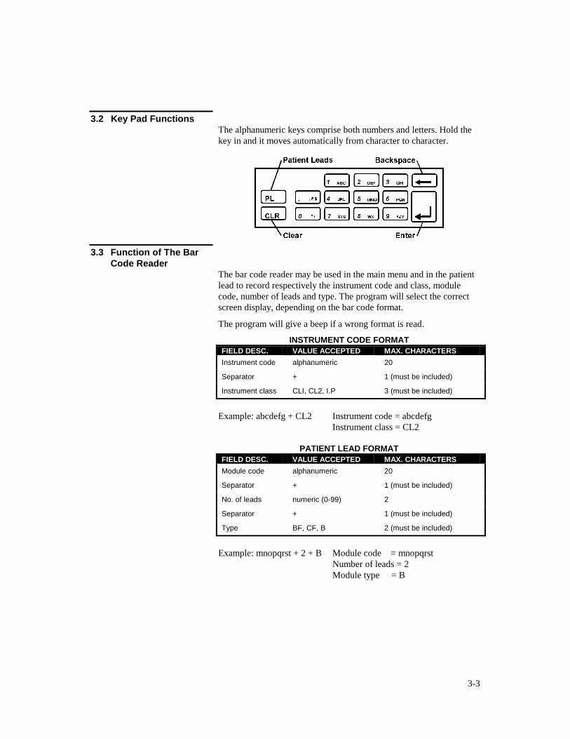
3.2 Key Pad Functions The alphanumeric keys comprise both numbers and letters. Hold the
key in and it moves automatically from character to character.
3.3 Function of The Bar
Code Reader The bar code reader may be used in the main menu and in the patient
lead to record respectively the instrument code and class, module
code, number of leads and type. The program will select the correct
screen display, depending on the bar code format.
The program will give a beep if a wrong format is read.
INSTRUMENT CODE FORMAT
FIELD DESC. VALUE ACCEPTED MAX. CHARACTERS
Instrument code alphanumeric 20
Separator + 1 (must be included)
Instrument class CLI, CL2, I.P 3 (must be included)
Example: abcdefg + CL2 Instrument code = abcdefg
Instrument class = CL2
PATIENT LEAD FORMAT
FIELD DESC. VALUE ACCEPTED MAX. CHARACTERS
Module code alphanumeric 20
Separator + 1 (must be included)
No. of leads numeric (0-99) 2
Separator + 1 (must be included)
Type BF, CF, B 2 (must be included)
Example: mnopqrst + 2 + B Module code = mnopqrst
Number of leads = 2
Module type = B
3-4
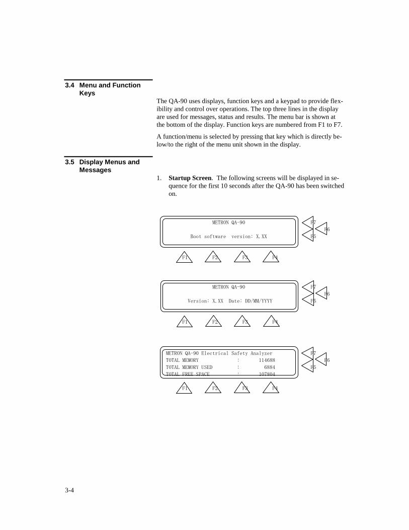
3.4 Menu and Function
Keys The QA-90 uses displays, function keys and a keypad to provide flex-
ibility and control over operations. The top three lines in the display
are used for messages, status and results. The menu bar is shown at
the bottom of the display. Function keys are numbered from F1 to F7.
A function/menu is selected by pressing that key which is directly be-
low/to the right of the menu unit shown in the display.
3.5 Display Menus and
Messages
1. Startup Screen. The following screens will be displayed in se-
quence for the first 10 seconds after the QA-90 has been switched
on.
METRON QA-90 F7
F6
Boot software version: X.XX F5
F1 F2 F3 F4
METRON QA-90 F7
F6
Version: X.XX Date: DD/MM/YYYY F5
F1 F2 F3 F4
METRON QA-90 Electrical Safety Analyzer F7
TOTAL MEMORY : 114688 F6
TOTAL MEMORY USED : 6884 F5
TOTAL FREE SPACE : 107804
F1 F2 F3 F4
3-5
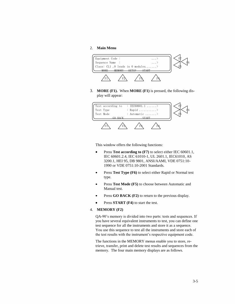
2. Main Menu
Equipment Code : ...> F7
Sequence Name : ...> F6
Class: CL1 ,0 leads in 0 modules.......> F5
MORE MEMORY SETUP START
F1 F2 F3 F4
3. MORE (F1). When MORE (F1) is pressed, the following dis-
play will appear:
Test according to : IEC60601.1 ......> F7
Test Type : Rapid ...........> F6
Test Mode : Automatic .......> F5
GO BACK START
F1 F2 F3 F4
This window offers the following functions:
Press Test according to (F7) to select either IEC 60601.1,
IEC 60601.2.4, IEC 61010-1, UL 2601.1, IEC61010, AS
3200.1, HEI 95, DB 9801, ANSI/AAMI, VDE 0751:10-
1990 or VDE 0751:10-2001 Standards.
Press Test Type (F6) to select either Rapid or Normal test
type.
Press Test Mode (F5) to choose between Automatic and
Manual test.
Press GO BACK (F2) to return to the previous display.
Press START (F4) to start the test.
4. MEMORY (F2)
QA-90’s memory is divided into two parts: tests and sequences. If
you have several equivalent instruments to test, you can define one
test sequence for all the instruments and store it as a sequence.
You use this sequence to test all the instruments and store each of
the test results with the instrument’s respective equipment code.
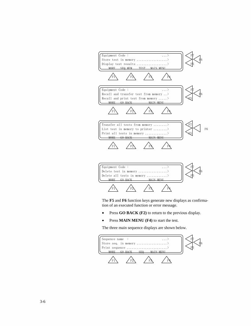
The functions in the MEMORY menus enable you to store, re-
trieve, transfer, print and delete test results and sequences from the
memory. The four main memory displays are as follows.
3-6
Equipment Code : ...> F7
Store test in memory ..................> F6
Display test results ..................> F5
MORE SEQ.MEM TEST MAIN MENU
F1 F2 F3 F4
Equipment Code : ...> F7
Recall and transfer test from memory ..> F6
Recall and print test from memory .....> F5
MORE GO BACK MAIN MENU
F1 F2 F3 F4
Transfer all tests from memory ........> F7
List test in memory to printer ........> F6
Print all tests in memory .............> F5
MORE GO BACK MAIN MENU
F1 F2 F3 F4
Equipment Code : ...> F7
Delete test in memory .................> F6
Delete all tests in memory ............> F5
MORE GO BACK MAIN MENU
F1 F2 F3 F4
The F5 and F6 function keys generate new displays as confirma-
tion of an executed function or error message.
Press GO BACK (F2) to return to the previous display.
Press MAIN MENU (F4) to start the test.
The three main sequence displays are shown below.
Sequence name : ...> F7
Store seq. in memory ..................> F6
Print sequence ........................> F5
MORE GO BACK SEQ MAIN MENU
F1 F2 F3 F4
3-7
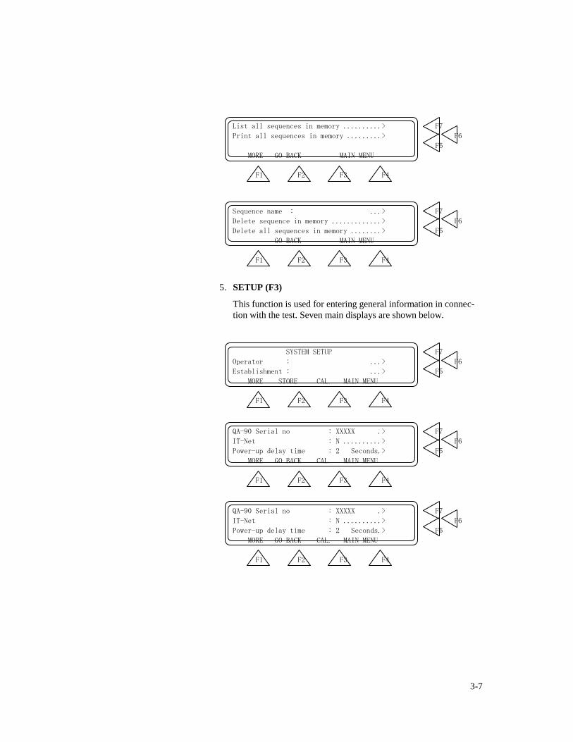
List all sequences in memory ..........> F7
Print all sequences in memory .........> F6
F5
MORE GO BACK MAIN MENU
F1 F2 F3 F4
Sequence name : ...> F7
Delete sequence in memory .............> F6
Delete all sequences in memory ........> F5
GO BACK MAIN MENU
F1 F2 F3 F4
5. SETUP (F3)
This function is used for entering general information in connec-
tion with the test. Seven main displays are shown below.
SYSTEM SETUP F7
Operator : ...> F6
Establishment : ...> F5
MORE STORE CAL. MAIN MENU
F1 F2 F3 F4
QA-90 Serial no : XXXXX .> F7
IT-Net : N ..........> F6
Power-up delay time : 2 Seconds.> F5
MORE GO BACK CAL. MAIN MENU
F1 F2 F3 F4
QA-90 Serial no : XXXXX .> F7
IT-Net : N ..........> F6
Power-up delay time : 2 Seconds.> F5
MORE GO BACK CAL. MAIN MENU
F1 F2 F3 F4
3-8
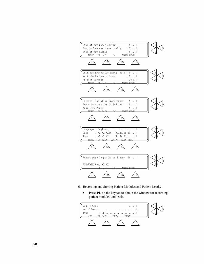
Stop at new power config : N ...> F7
Stop before new power config : N ...> F6
Stop at new module : N ...> F5
MORE GO BACK CAL. MAIN MENU
F1 F2 F3 F4
Multiple Protective Earth Tests : N ...> F7
Multiple Enclosure Tests : N ...> F6
PE Test Current : 25 A.> F5
MORE GO BACK CAL. MAIN MENU
F1 F2 F3 F4
External Isolating Transformer : N ...> F7
Acoustic alarm for failed test : Y ...> F6
Auxiliary Power : N ...> F5
MORE GO BACK CAL. MAIN MENU
F1 F2 F3 F4
Language : English ....................> F7
Date : XX/XX/XXXX (DD/MM/YYYY) ...> F6
Time : XX:XX:XX (HH:MM:SS) .....> F5
MORE GO BACK AM/PM MAIN MENU
F1 F2 F3 F4
Report page length(no of lines) :58 ...> F7
F6
FIRMWARE Ver. XX.XX F5
GO BACK CAL. MAIN MENU
F1 F2 F3 F4
6. Recording and Storing Patient Modules and Patient Leads.
Press PL on the keypad to obtain the window for recording
patient modules and leads.
Module Code : .....> F7
No of leads : .......................> F6
Type : CF.......................> F5
ADD GO BACK PREV. NEXT
3-9
F1 F2 F3 F4
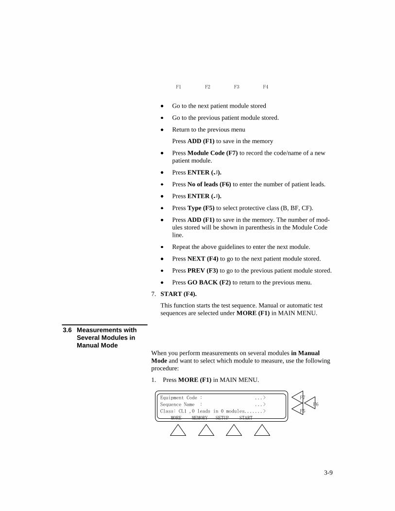
Go to the next patient module stored
Go to the previous patient module stored.
Return to the previous menu
Press ADD (F1) to save in the memory
Press Module Code (F7) to record the code/name of a new
patient module.
Press ENTER ( ).
Press No of leads (F6) to enter the number of patient leads.
Press ENTER ( ).
Press Type (F5) to select protective class (B, BF, CF).
Press ADD (F1) to save in the memory. The number of mod-
ules stored will be shown in parenthesis in the Module Code
line.
Repeat the above guidelines to enter the next module.
Press NEXT (F4) to go to the next patient module stored.
Press PREV (F3) to go to the previous patient module stored.
Press GO BACK (F2) to return to the previous menu.
7. START (F4).
This function starts the test sequence. Manual or automatic test
sequences are selected under MORE (F1) in MAIN MENU.
3.6 Measurements with
Several Modules in
Manual Mode
When you perform measurements on several modules in Manual
Mode and want to select which module to measure, use the following
procedure:
1. Press MORE (F1) in MAIN MENU.
Equipment Code : ...> F7
Sequence Name : ...> F6
Class: CL1 ,0 leads in 0 modules.......> F5
MORE MEMORY SETUP START
3-10
F1 F2 F3 F4
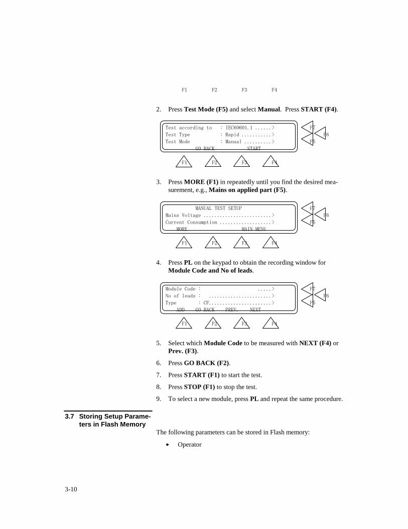
2. Press Test Mode (F5) and select Manual. Press START (F4).
Test according to : IEC60601.1 ......> F7
Test Type : Rapid ...........> F6
Test Mode : Manual ..........> F5
GO BACK START
F1 F2 F3 F4
3. Press MORE (F1) in repeatedly until you find the desired mea-
surement, e.g., Mains on applied part (F5).
MANUAL TEST SETUP F7
Mains Voltage .........................> F6
Current Consumption ...................> F5
MORE MAIN MENU
F1 F2 F3 F4
4. Press PL on the keypad to obtain the recording window for
Module Code and No of leads.
Module Code : .....> F7
No of leads : .......................> F6
Type : CF.......................> F5
ADD GO BACK PREV. NEXT
F1 F2 F3 F4
5. Select which Module Code to be measured with NEXT (F4) or
Prev. (F3).
6. Press GO BACK (F2).
7. Press START (F1) to start the test.
8. Press STOP (F1) to stop the test.
9. To select a new module, press PL and repeat the same procedure.
3.7 Storing Setup Parame-
ters in Flash Memory The following parameters can be stored in Flash memory:
Operator
3-11
Establishment
Serial Number
Language
Calibration parameters
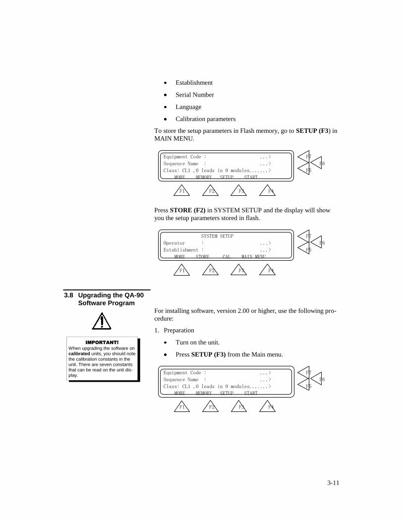
To store the setup parameters in Flash memory, go to SETUP (F3) in
MAIN MENU.
Equipment Code : ...> F7
Sequence Name : ...> F6
Class: CL1 ,0 leads in 0 modules.......> F5
MORE MEMORY SETUP START
F1 F2 F3 F4
Press STORE (F2) in SYSTEM SETUP and the display will show
you the setup parameters stored in flash.
SYSTEM SETUP F7
Operator : ...> F6
Establishment : ...> F5
MORE STORE CAL. MAIN MENU
F1 F2 F3 F4
3.8 Upgrading the QA-90
Software Program For installing software, version 2.00 or higher, use the following pro-
cedure:
1. Preparation
Turn on the unit.
Press SETUP (F3) from the Main menu.
Equipment Code : ...> F7
Sequence Name : ...> F6
Class: CL1 ,0 leads in 0 modules.......> F5
MORE MEMORY SETUP START
F1 F2 F3 F4
IMPORTANT!
When upgrading the software on calibrated units, you should note
the calibration constants in the unit. There are seven constants that can be read on the unit dis-play.

3-12
Press CAL (F3) from the System Setup.
SYSTEM SETUP F7
Operator : ...> F6
Establishment : ...> F5
MORE STORE CAL. MAIN MENU
F1 F2 F3 F4
Then go to the hidden menu under (F1), in the menu for Self
Calibration.
SELF CALIBRATION F7
Calibrate test lead, enclosure/earth ..> F6
Calibrate test lead, dual float .......> F5
GO BACK MAIN MENU
F1 F2 F3 F4
Note the values on the three constants that appear on the dis-
play.
Press MORE (F1) to get the three next constants.
Press MORE (F1) to get the last constant. NB: Automatic
MAP calibration: ONLY for production calibration.
The QA-90 software upgrade contains two files: comqa90.exe,
the communication between computer and the QA-90, and;
qa90-xxx.a07 is the program for QA-90. (XXX indicates the
version of the firmware.)
2. Prepare the QA-90 for the software upgrade.
Reading the program to Flash memory in the QA-90.
Press and hold PL and CLR at the same time while turning
the QA-90 on.
The display will show the following:
The software in the QA-90 is missing.
To download new software, run COMMQA90
on the PC and press ENTER on QA-90
3-13
The QA-90 is ready to receive data.
3. Prepare the PC for the upgrade.
Connect an RS-232 cable between PC and QA-90.
Insert the disk that contains the QA-90 upgrade program.
Write COMMQA90.EXE (DOS)
Press ENTER ( )
A menu will appear on the computer:
Choose menu 1 SET PARAMETERS and choose new pa-
rameters or default values.
Choose menu 2 START COMMUNICATION by pressing
2. Enter filename QA90-XXX.A07 where XXX is the version
of the firmware. Check the file.
Press ENTER ( ) on the computer.
Press ENTER ( ) on the QA-90 and the transmission will
start.
If the communication is successful, >>>>>>> will appear conti-
nuously at the display on the QA-90. When the program is trans-
mitted, a normal startup menu will appear on the QA-90. The
computer will either show a picture for program transmission, or a
clear screen.
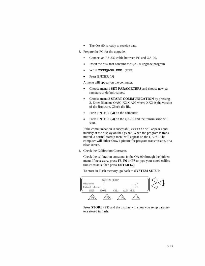
4. Check the Calibration Constants
Check the calibration constants in the QA-90 through the hidden
menu. If necessary, press F5, F6 or F7 to type your noted calibra-
tion constants, then press ENTER ( ).
To store in Flash memory, go back to SYSTEM SETUP.
SYSTEM SETUP F7
Operator : ...> F6
Establishment : ...> F5
MORE STORE CAL. MAIN MENU
F1 F2 F3 F4
Press STORE (F2) and the display will show you setup parame-
ters stored in flash.

3-14
3.9 Cleaning the QA-90 The outside of the instrument may be cleaned using a damp cloth and
mild detergent. Please note that solvents like Methanol may dam-
mage the overlay and cabinet.

3-15
This page intentionally left blank.

4-1
4. Example Test Measurements
This chapter contains test examples for the QA-90, illustrating equip-
ment connections for the tests, as well as step-by-step procedures for
obtaining desired test measurements. For more information on safety
testing, and an explanation of protective classes, refer to Appendix A,
IEC 60601.1, UL 2601.1 and VDE 0751 Testing.
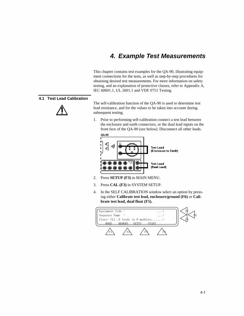
4.1 Test Lead Calibration The self-calibration function of the QA-90 is used to determine test
lead resistance, and for the values to be taken into account during
subsequent testing.
1. Prior to performing self-calibration connect a test lead between
the enclosure and earth connectors, or the dual lead inputs on the
front face of the QA-90 (see below). Disconnect all other leads.
2. Press SETUP (F3) in MAIN MENU.
3. Press CAL (F3) in SYSTEM SETUP.
4. In the SELF CALIBRATION window select an option by press-
ing either Calibrate test lead, enclosure/ground (F6) or Cali-
brate test lead, dual float (F5).
Equipment Code : ...> F7
Sequence Name : ...> F6
Class: CL1 ,0 leads in 0 modules.......> F5
MORE MEMORY SETUP START
F1 F2 F3 F4
4-2
SYSTEM SETUP F7
Operator : ...> F6
Establishment : ...> F5
MORE STORE CAL. MAIN MENU
F1 F2 F3 F4
SELF CALIBRATION F7
Calibrate test lead, enclosure/earth ..> F6
Calibrate test lead, dual float .......> F5
GO BACK MAIN MENU
F1 F2 F3 F4
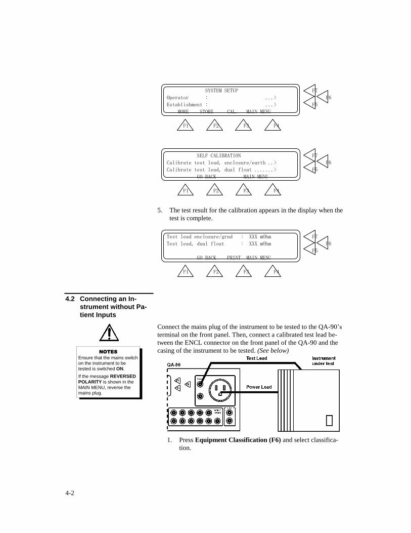
5. The test result for the calibration appears in the display when the
test is complete.
Test lead enclosure/grnd : XXX mOhm F7
Test lead, dual float : XXX mOhm F6
F5
GO BACK PRINT MAIN MENU
F1 F2 F3 F4
4.2 Connecting an In-
strument without Pa-
tient Inputs
Connect the mains plug of the instrument to be tested to the QA-90’s
terminal on the front panel. Then, connect a calibrated test lead be-
tween the ENCL connector on the front panel of the QA-90 and the
casing of the instrument to be tested. (See below)
1. Press Equipment Classification (F6) and select classifica-
tion.
NOTES
Ensure that the mains switch on the instrument to be
tested is switched ON.
If the message REVERSED
POLARITY is shown in the
MAIN MENU, reverse the mains plug.
4-3
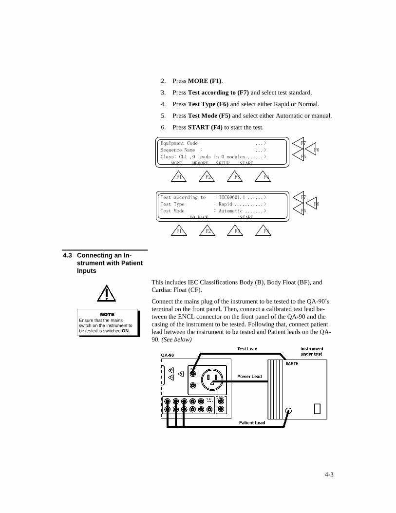
2. Press MORE (F1).
3. Press Test according to (F7) and select test standard.
4. Press Test Type (F6) and select either Rapid or Normal.
5. Press Test Mode (F5) and select either Automatic or manual.
6. Press START (F4) to start the test.
Equipment Code : ...> F7
Sequence Name : ...> F6
Class: CL1 ,0 leads in 0 modules.......> F5
MORE MEMORY SETUP START
F1 F2 F3 F4
Test according to : IEC60601.1 ......> F7
Test Type : Rapid ...........> F6
Test Mode : Automatic .......> F5
GO BACK START
F1 F2 F3 F4
4.3 Connecting an In-
strument with Patient
Inputs
This includes IEC Classifications Body (B), Body Float (BF), and
Cardiac Float (CF).
Connect the mains plug of the instrument to be tested to the QA-90’s
terminal on the front panel. Then, connect a calibrated test lead be-
tween the ENCL connector on the front panel of the QA-90 and the
casing of the instrument to be tested. Following that, connect patient
lead between the instrument to be tested and Patient leads on the QA-
90. (See below)
NOTE
Ensure that the mains switch on the instrument to be tested is switched ON.
4-4
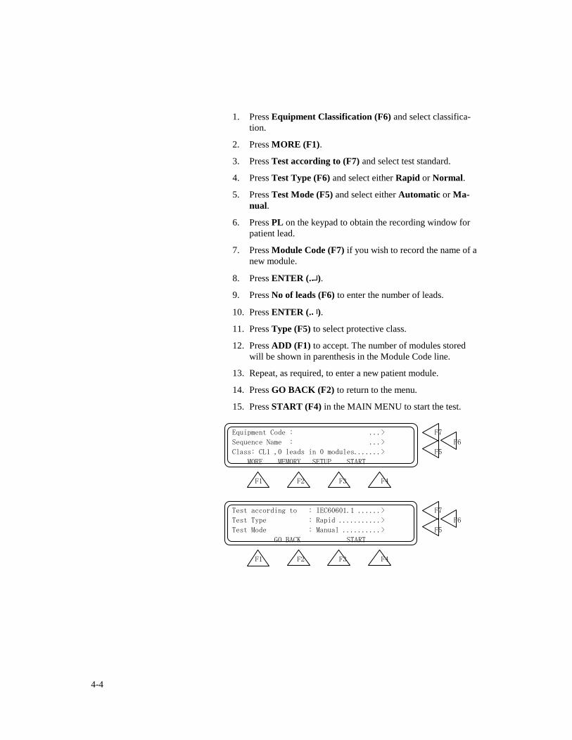
1. Press Equipment Classification (F6) and select classifica-
tion.
2. Press MORE (F1).
3. Press Test according to (F7) and select test standard.
4. Press Test Type (F6) and select either Rapid or Normal.
5. Press Test Mode (F5) and select either Automatic or Ma-
nual.
6. Press PL on the keypad to obtain the recording window for
patient lead.
7. Press Module Code (F7) if you wish to record the name of a
new module.
8. Press ENTER (. ).
9. Press No of leads (F6) to enter the number of leads.
10. Press ENTER (. ).
11. Press Type (F5) to select protective class.
12. Press ADD (F1) to accept. The number of modules stored
will be shown in parenthesis in the Module Code line.
13. Repeat, as required, to enter a new patient module.
14. Press GO BACK (F2) to return to the menu.
15. Press START (F4) in the MAIN MENU to start the test.
Equipment Code : ...> F7
Sequence Name : ...> F6
Class: CL1 ,0 leads in 0 modules.......> F5
MORE MEMORY SETUP START
F1 F2 F3 F4
Test according to : IEC60601.1 ......> F7
Test Type : Rapid ...........> F6
Test Mode : Manual ..........> F5
GO BACK START
F1 F2 F3 F4
4-5
Module Code : .....> F7
No of leads : .......................> F6
Type : CF.......................> F5
ADD GO BACK PREV. NEXT
F1 F2 F3 F4
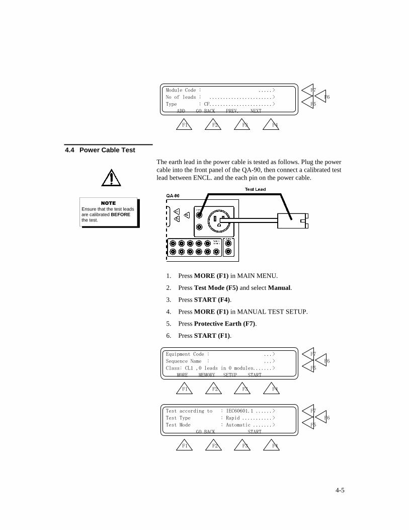
4.4 Power Cable Test
The earth lead in the power cable is tested as follows. Plug the power
cable into the front panel of the QA-90, then connect a calibrated test
lead between ENCL. and the each pin on the power cable.
1. Press MORE (F1) in MAIN MENU.
2. Press Test Mode (F5) and select Manual.
3. Press START (F4).
4. Press MORE (F1) in MANUAL TEST SETUP.
5. Press Protective Earth (F7).
6. Press START (F1).
Equipment Code : ...> F7
Sequence Name : ...> F6
Class: CL1 ,0 leads in 0 modules.......> F5
MORE MEMORY SETUP START
F1 F2 F3 F4
Test according to : IEC60601.1 ......> F7
Test Type : Rapid ...........> F6
Test Mode : Automatic .......> F5
GO BACK START
F1 F2 F3 F4
NOTE
Ensure that the test leads are calibrated BEFORE
the test.
4-6
MANUAL TEST SETUP F7
Mains Voltage .........................> F6
Current Consumption ...................> F5
MORE MAIN MENU
F1 F2 F3 F4
Protective Earth ......................> F7
Insulation Resistance .................> F6
Earth Leakage Current .................> F5
MORE GO BACK MAIN MENU
F1 F2 F3 F4
Time : Seconds F7
Result : mOhm F6
Limit : mOhm F5
START GO BACK PRINT MAIN MENU
F1 F2 F3 F4
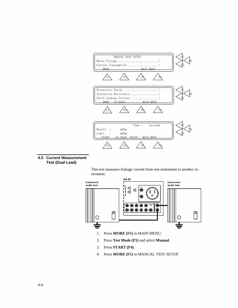
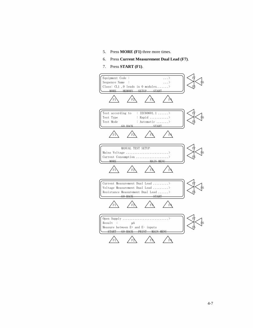
4.5 Current Measurement
Test (Dual Lead)
This test measures leakage current from one instrument to another in-
strument.
1. Press MORE (F1) in MAIN MENU.
2. Press Test Mode (F5) and select Manual.
3. Press START (F4).
4. Press MORE (F1) in MANUAL TEST SETUP.
4-7
5. Press MORE (F1) three more times.
6. Press Current Measurement Dual Lead (F7).
7. Press START (F1).
Equipment Code : ...> F7
Sequence Name : ...> F6
Class: CL1 ,0 leads in 0 modules.......> F5
MORE MEMORY SETUP START
F1 F2 F3 F4
Test according to : IEC60601.1 ......> F7
Test Type : Rapid ...........> F6
Test Mode : Automatic .......> F5
GO BACK START
F1 F2 F3 F4
MANUAL TEST SETUP F7
Mains Voltage .........................> F6
Current Consumption ...................> F5
MORE MAIN MENU
F1 F2 F3 F4
Current Measurement Dual Lead .........> F7
Voltage Measurement Dual Lead .........> F6
Resistance Measurement Dual Lead ......> F5
GO BACK START
F1 F2 F3 F4
Open Supply ...........................> F7
Result : µA F6
Measure between E+ and E- inputs F5
START GO BACK PRINT MAIN MENU
F1 F2 F3 F4
4-8
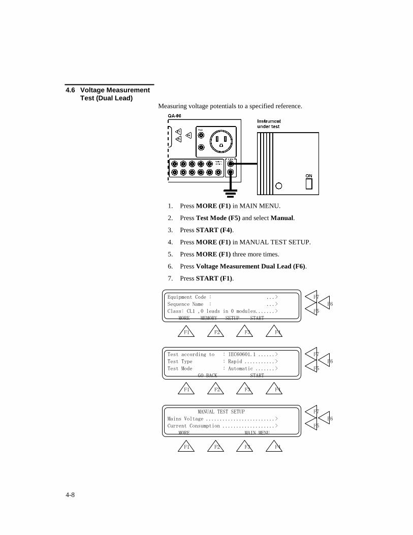
4.6 Voltage Measurement
Test (Dual Lead) Measuring voltage potentials to a specified reference.
1. Press MORE (F1) in MAIN MENU.
2. Press Test Mode (F5) and select Manual.
3. Press START (F4).
4. Press MORE (F1) in MANUAL TEST SETUP.
5. Press MORE (F1) three more times.
6. Press Voltage Measurement Dual Lead (F6).
7. Press START (F1).
Equipment Code : ...> F7
Sequence Name : ...> F6
Class: CL1 ,0 leads in 0 modules.......> F5
MORE MEMORY SETUP START
F1 F2 F3 F4
Test according to : IEC60601.1 ......> F7
Test Type : Rapid ...........> F6
Test Mode : Automatic .......> F5
GO BACK START
F1 F2 F3 F4
MANUAL TEST SETUP F7
Mains Voltage .........................> F6
Current Consumption ...................> F5
MORE MAIN MENU
F1 F2 F3 F4

4-9
4-10
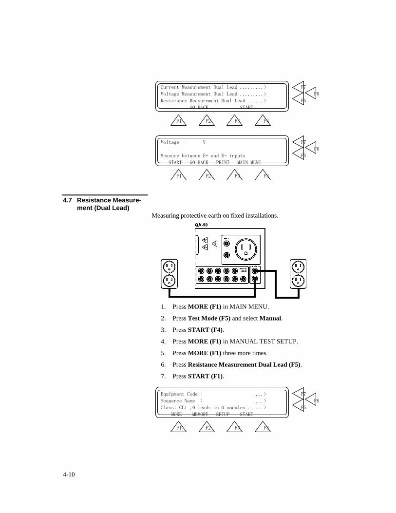
Current Measurement Dual Lead .........> F7
Voltage Measurement Dual Lead .........> F6
Resistance Measurement Dual Lead ......> F5
GO BACK START
F1 F2 F3 F4
Voltage : V F7
F6
Measure between E+ and E- inputs F5
START GO BACK PRINT MAIN MENU
F1 F2 F3 F4
4.7 Resistance Measure-
ment (Dual Lead) Measuring protective earth on fixed installations.
1. Press MORE (F1) in MAIN MENU.
2. Press Test Mode (F5) and select Manual.
3. Press START (F4).
4. Press MORE (F1) in MANUAL TEST SETUP.
5. Press MORE (F1) three more times.
6. Press Resistance Measurement Dual Lead (F5).
7. Press START (F1).
Equipment Code : ...> F7
Sequence Name : ...> F6
Class: CL1 ,0 leads in 0 modules.......> F5
MORE MEMORY SETUP START
F1 F2 F3 F4
4-11
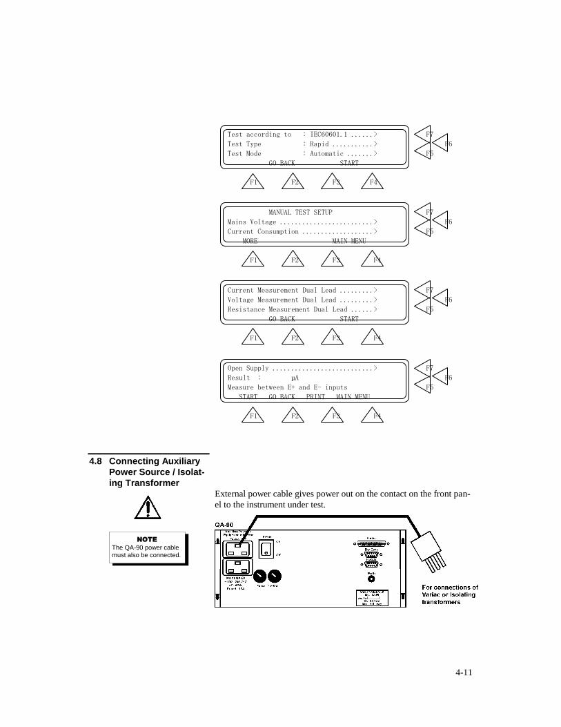
Test according to : IEC60601.1 ......> F7
Test Type : Rapid ...........> F6
Test Mode : Automatic .......> F5
GO BACK START
F1 F2 F3 F4
MANUAL TEST SETUP F7
Mains Voltage .........................> F6
Current Consumption ...................> F5
MORE MAIN MENU
F1 F2 F3 F4
Current Measurement Dual Lead .........> F7
Voltage Measurement Dual Lead .........> F6
Resistance Measurement Dual Lead ......> F5
GO BACK START
F1 F2 F3 F4
Open Supply ...........................> F7
Result : µA F6
Measure between E+ and E- inputs F5
START GO BACK PRINT MAIN MENU
F1 F2 F3 F4
4.8 Connecting Auxiliary
Power Source / Isolat-
ing Transformer External power cable gives power out on the contact on the front pan-
el to the instrument under test.
NOTE
The QA-90 power cable must also be connected.
4-12
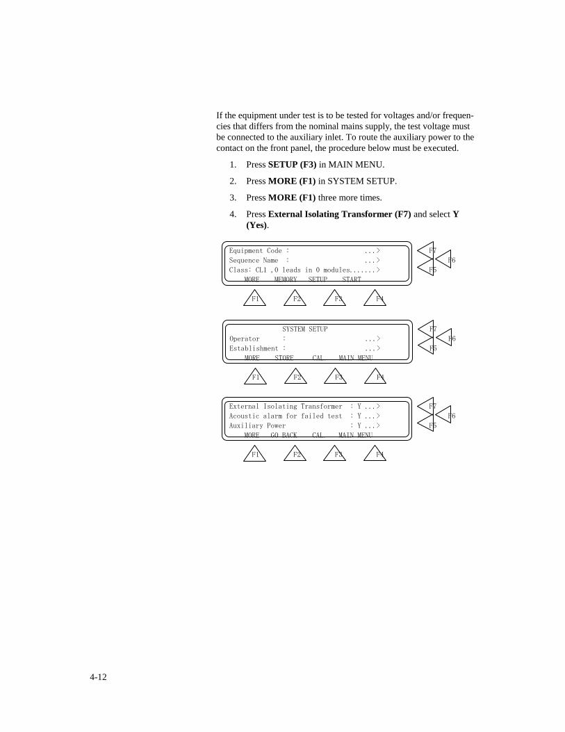
If the equipment under test is to be tested for voltages and/or frequen-
cies that differs from the nominal mains supply, the test voltage must
be connected to the auxiliary inlet. To route the auxiliary power to the
contact on the front panel, the procedure below must be executed.
1. Press SETUP (F3) in MAIN MENU.
2. Press MORE (F1) in SYSTEM SETUP.
3. Press MORE (F1) three more times.
4. Press External Isolating Transformer (F7) and select Y
(Yes).
Equipment Code : ...> F7
Sequence Name : ...> F6
Class: CL1 ,0 leads in 0 modules.......> F5
MORE MEMORY SETUP START
F1 F2 F3 F4
SYSTEM SETUP F7
Operator : ...> F6
Establishment : ...> F5
MORE STORE CAL. MAIN MENU
F1 F2 F3 F4
External Isolating Transformer : Y ...> F7
Acoustic alarm for failed test : Y ...> F6
Auxiliary Power : Y ...> F5
MORE GO BACK CAL. MAIN MENU
F1 F2 F3 F4

4-13
This page intentionally left blank.

4-14
This page intentionally left blank.
A-1
APPENDIX A: IEC 60601.1, UL 2601.1 AND VDE 0751 TESTING
This appendix describes International Electrotechnical Committee (IEC) Standard 60601.1, Underwri-
ters Laboratories (UL) Standard 2601.1, and Verband Deutscher Elektrotechniker e.V. (VDE) 0751
Standard tests, their functions, applicability, and equipment connections.
A.1 Classification of Equipment
Electrical safety begins with considering the mains electricity supply, and how to feed that into an item
of equipment so that it is able to power the electronics internally and, at the same time, ensure that there
is no possibility of the mains power coming into contact with either the patient, user or a third person.
The classification of equipment under IEC 601.1 and UL 2601.1 describe how the mains part insulation
is achieved. The techniques used include: air clearance; insulating materials (basic or functional insula-
tion); creepage distances, and; double insulation
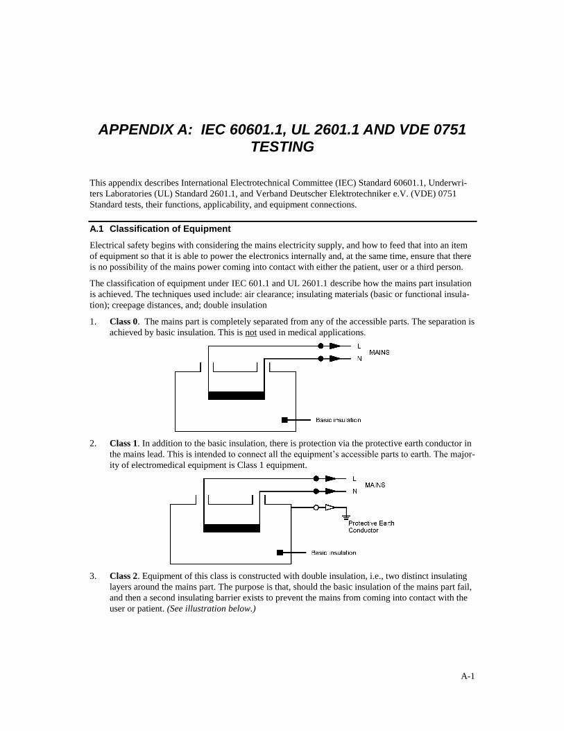
1. Class 0. The mains part is completely separated from any of the accessible parts. The separation is
achieved by basic insulation. This is not used in medical applications.
2. Class 1. In addition to the basic insulation, there is protection via the protective earth conductor in
the mains lead. This is intended to connect all the equipment’s accessible parts to earth. The major-
ity of electromedical equipment is Class 1 equipment.
3. Class 2. Equipment of this class is constructed with double insulation, i.e., two distinct insulating
layers around the mains part. The purpose is that, should the basic insulation of the mains part fail,
and then a second insulating barrier exists to prevent the mains from coming into contact with the
user or patient. (See illustration below.)
A-2
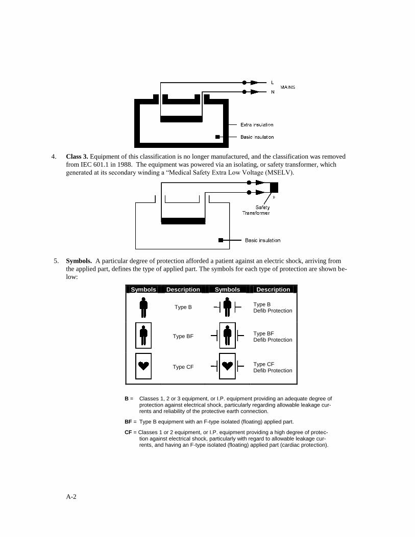
4. Class 3. Equipment of this classification is no longer manufactured, and the classification was removed
from IEC 601.1 in 1988. The equipment was powered via an isolating, or safety transformer, which
generated at its secondary winding a “Medical Safety Extra Low Voltage (MSELV).
5. Symbols. A particular degree of protection afforded a patient against an electric shock, arriving from
the applied part, defines the type of applied part. The symbols for each type of protection are shown be-
low:
Symbols Description Symbols Description
Type B
Type B Defib Protection
Type BF
Type BF Defib Protection
Type CF
Type CF Defib Protection
B = Classes 1, 2 or 3 equipment, or I.P. equipment providing an adequate degree of protection against electrical shock, particularly regarding allowable leakage cur-rents and reliability of the protective earth connection.
BF = Type B equipment with an F-type isolated (floating) applied part.
CF = Classes 1 or 2 equipment, or I.P. equipment providing a high degree of protec-tion against electrical shock, particularly with regard to allowable leakage cur-rents, and having an F-type isolated (floating) applied part (cardiac protection).
A-3
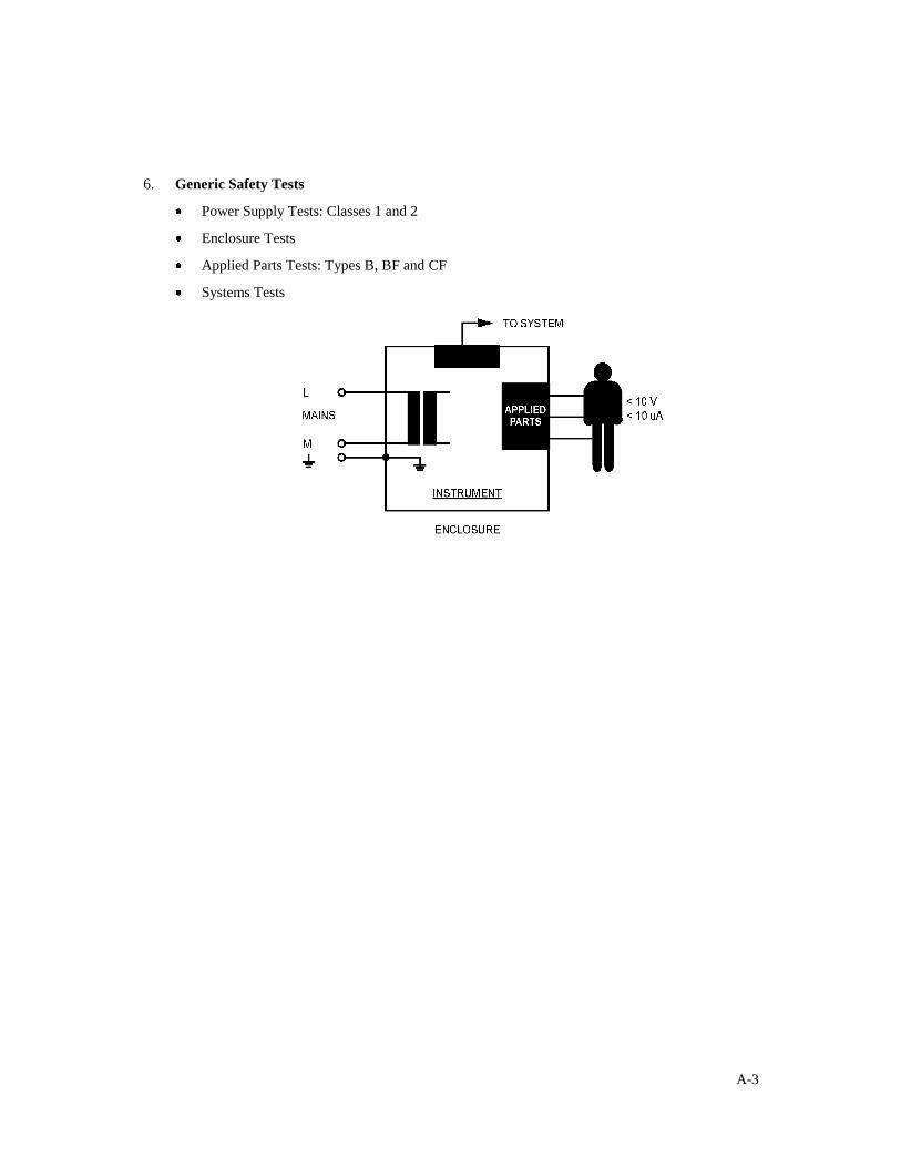
6. Generic Safety Tests
Power Supply Tests: Classes 1 and 2
Enclosure Tests
Applied Parts Tests: Types B, BF and CF
Systems Tests
A-4
A.2 Tests on Mains Powered Class 1 & 2 Equipment According To IEC 60601.1/UL
2601.1
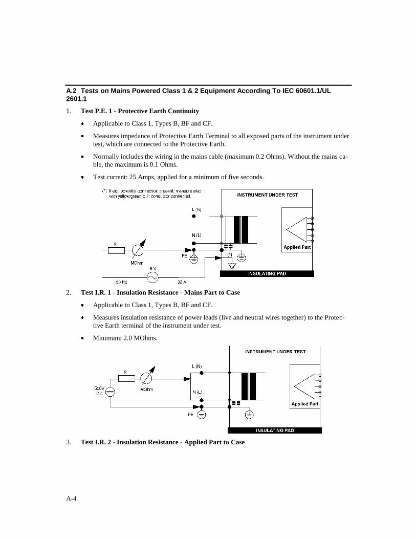
1. Test P.E. 1 - Protective Earth Continuity
Applicable to Class 1, Types B, BF and CF.
Measures impedance of Protective Earth Terminal to all exposed parts of the instrument under
test, which are connected to the Protective Earth.
Normally includes the wiring in the mains cable (maximum 0.2 Ohms). Without the mains ca-
ble, the maximum is 0.1 Ohms.
Test current: 25 Amps, applied for a minimum of five seconds.
2. Test I.R. 1 - Insulation Resistance - Mains Part to Case
Applicable to Class 1, Types B, BF and CF.
Measures insulation resistance of power leads (live and neutral wires together) to the Protec-
tive Earth terminal of the instrument under test.
Minimum: 2.0 MOhms.
3. Test I.R. 2 - Insulation Resistance - Applied Part to Case
A-5
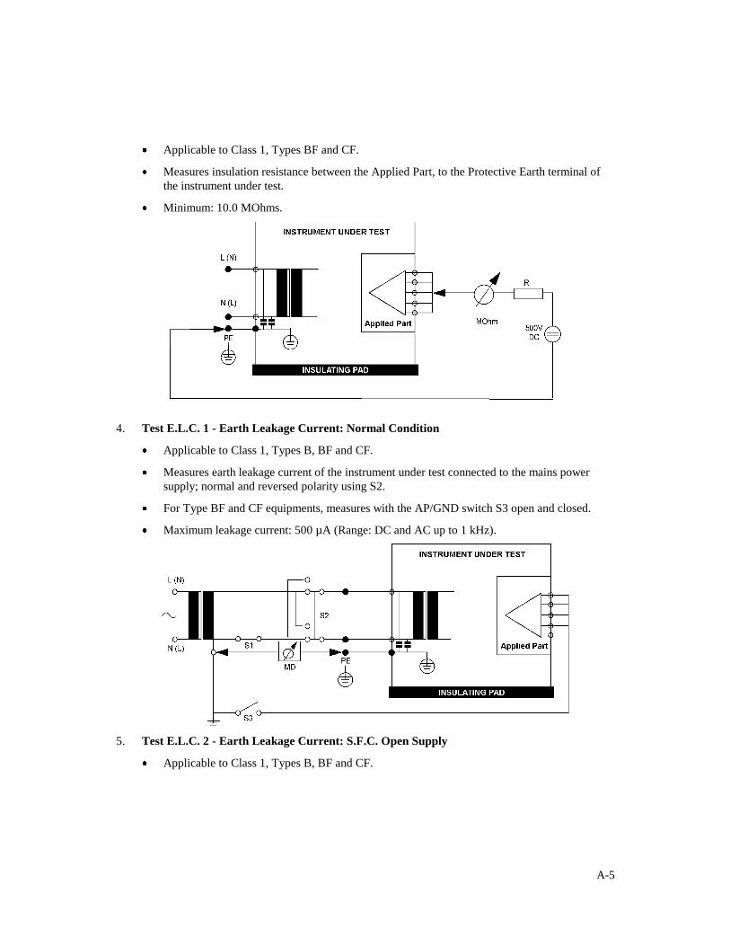
Applicable to Class 1, Types BF and CF.
Measures insulation resistance between the Applied Part, to the Protective Earth terminal of
the instrument under test.
Minimum: 10.0 MOhms.
4. Test E.L.C. 1 - Earth Leakage Current: Normal Condition
Applicable to Class 1, Types B, BF and CF.
Measures earth leakage current of the instrument under test connected to the mains power
supply; normal and reversed polarity using S2.
For Type BF and CF equipments, measures with the AP/GND switch S3 open and closed.
Maximum leakage current: 500 µA (Range: DC and AC up to 1 kHz).
5. Test E.L.C. 2 - Earth Leakage Current: S.F.C. Open Supply
Applicable to Class 1, Types B, BF and CF.
A-6
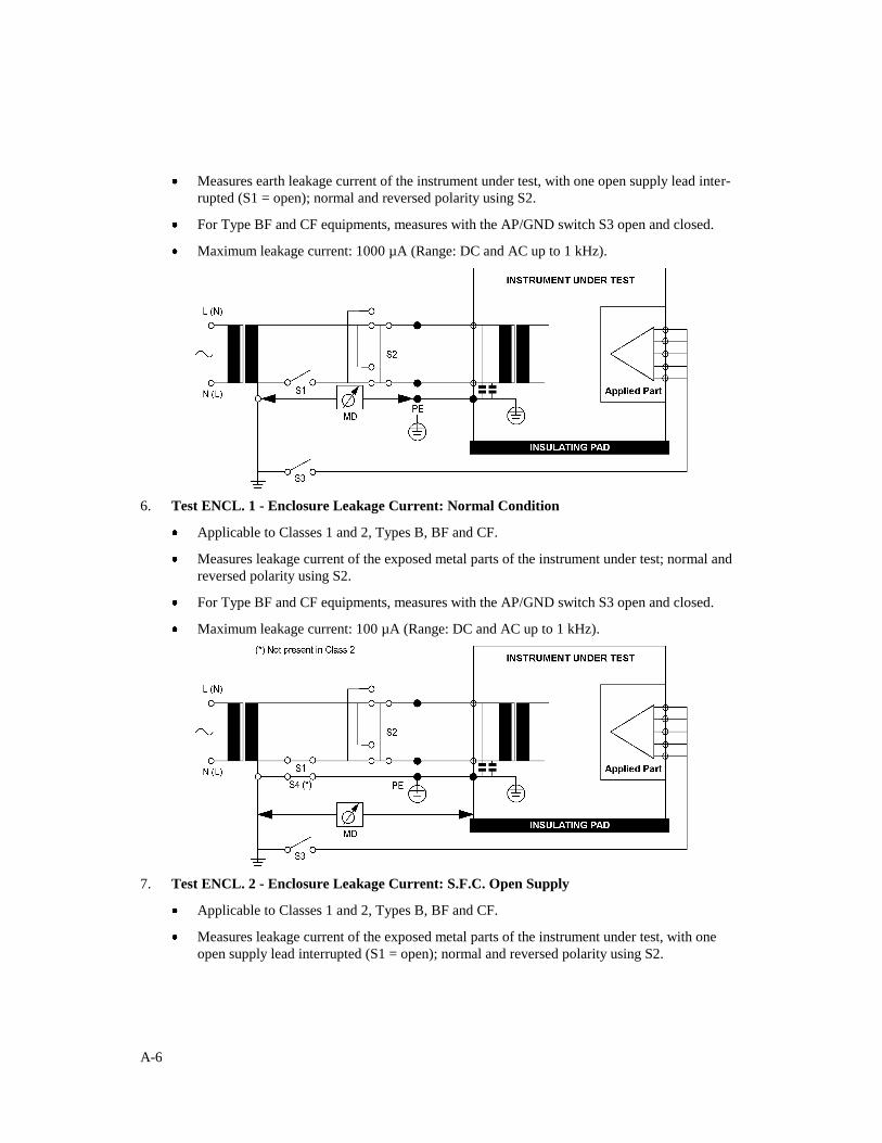
Measures earth leakage current of the instrument under test, with one open supply lead inter-
rupted (S1 = open); normal and reversed polarity using S2.
For Type BF and CF equipments, measures with the AP/GND switch S3 open and closed.
Maximum leakage current: 1000 µA (Range: DC and AC up to 1 kHz).
6. Test ENCL. 1 - Enclosure Leakage Current: Normal Condition
Applicable to Classes 1 and 2, Types B, BF and CF.
Measures leakage current of the exposed metal parts of the instrument under test; normal and
reversed polarity using S2.
For Type BF and CF equipments, measures with the AP/GND switch S3 open and closed.
Maximum leakage current: 100 µA (Range: DC and AC up to 1 kHz).
7. Test ENCL. 2 - Enclosure Leakage Current: S.F.C. Open Supply
Applicable to Classes 1 and 2, Types B, BF and CF.
Measures leakage current of the exposed metal parts of the instrument under test, with one
open supply lead interrupted (S1 = open); normal and reversed polarity using S2.
A-7
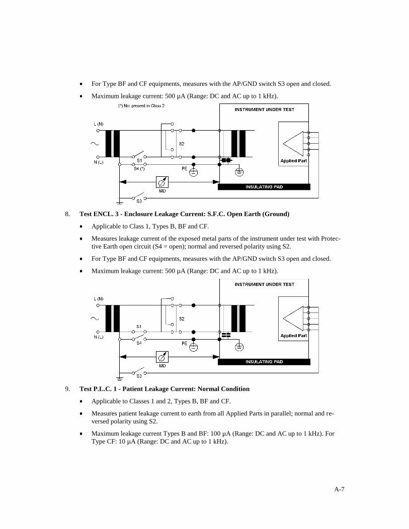
For Type BF and CF equipments, measures with the AP/GND switch S3 open and closed.
Maximum leakage current: 500 µA (Range: DC and AC up to 1 kHz).
8. Test ENCL. 3 - Enclosure Leakage Current: S.F.C. Open Earth (Ground)
Applicable to Class 1, Types B, BF and CF.
Measures leakage current of the exposed metal parts of the instrument under test with Protec-
tive Earth open circuit (S4 = open); normal and reversed polarity using S2.
For Type BF and CF equipments, measures with the AP/GND switch S3 open and closed.
Maximum leakage current: 500 µA (Range: DC and AC up to 1 kHz).
9. Test P.L.C. 1 - Patient Leakage Current: Normal Condition
Applicable to Classes 1 and 2, Types B, BF and CF.
Measures patient leakage current to earth from all Applied Parts in parallel; normal and re-
versed polarity using S2.
Maximum leakage current Types B and BF: 100 µA (Range: DC and AC up to 1 kHz). For
Type CF: 10 µA (Range: DC and AC up to 1 kHz).
A-8
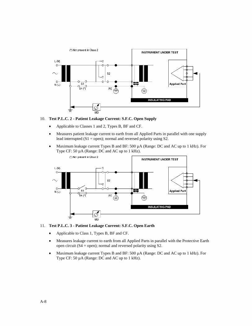
10. Test P.L.C. 2 - Patient Leakage Current: S.F.C. Open Supply
Applicable to Classes 1 and 2, Types B, BF and CF.
Measures patient leakage current to earth from all Applied Parts in parallel with one supply
lead interrupted (S1 = open); normal and reversed polarity using S2.
Maximum leakage current Types B and BF: 500 µA (Range: DC and AC up to 1 kHz). For
Type CF: 50 µA (Range: DC and AC up to 1 kHz).
11. Test P.L.C. 3 - Patient Leakage Current: S.F.C. Open Earth
Applicable to Class 1, Types B, BF and CF.
Measures leakage current to earth from all Applied Parts in parallel with the Protective Earth
open circuit (S4 = open); normal and reversed polarity using S2.
Maximum leakage current Types B and BF: 500 µA (Range: DC and AC up to 1 kHz). For
Type CF: 50 µA (Range: DC and AC up to 1 kHz).
A-9
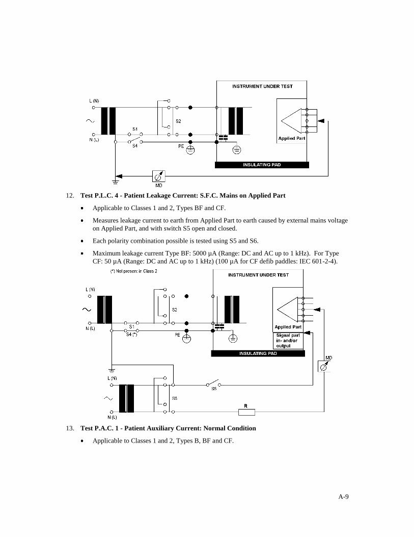
12. Test P.L.C. 4 - Patient Leakage Current: S.F.C. Mains on Applied Part
Applicable to Classes 1 and 2, Types BF and CF.
Measures leakage current to earth from Applied Part to earth caused by external mains voltage
on Applied Part, and with switch S5 open and closed.
Each polarity combination possible is tested using S5 and S6.
Maximum leakage current Type BF: 5000 µA (Range: DC and AC up to 1 kHz). For Type
CF: 50 µA (Range: DC and AC up to 1 kHz) (100 µA for CF defib paddles: IEC 601-2-4).
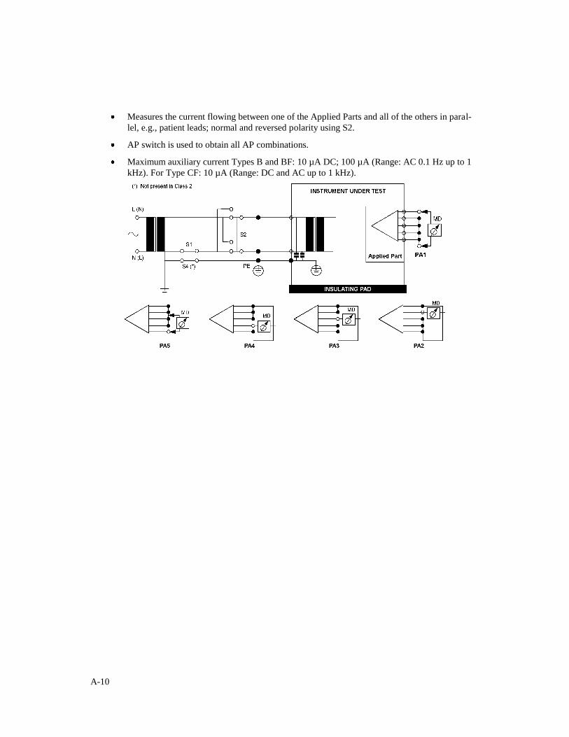
13. Test P.A.C. 1 - Patient Auxiliary Current: Normal Condition
Applicable to Classes 1 and 2, Types B, BF and CF.
A-10
Measures the current flowing between one of the Applied Parts and all of the others in paral-
lel, e.g., patient leads; normal and reversed polarity using S2.
AP switch is used to obtain all AP combinations.
Maximum auxiliary current Types B and BF: 10 µA DC; 100 µA (Range: AC 0.1 Hz up to 1
kHz). For Type CF: 10 µA (Range: DC and AC up to 1 kHz).
A-11
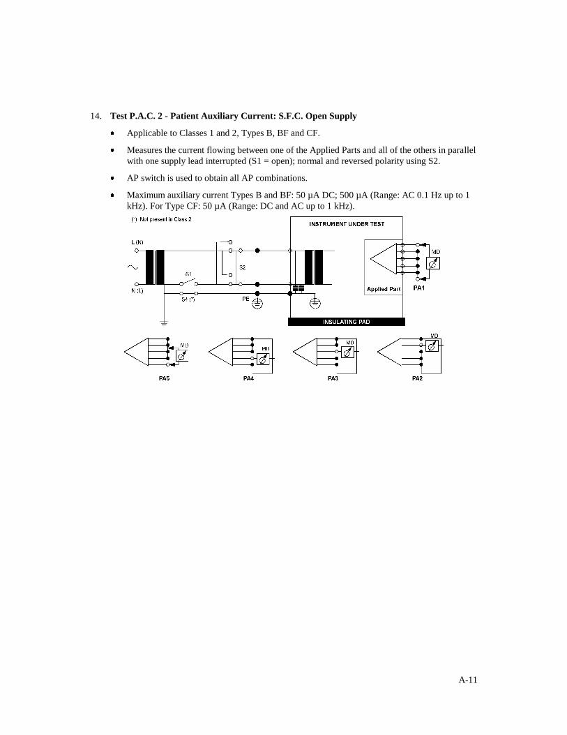
14. Test P.A.C. 2 - Patient Auxiliary Current: S.F.C. Open Supply
Applicable to Classes 1 and 2, Types B, BF and CF.
Measures the current flowing between one of the Applied Parts and all of the others in parallel
with one supply lead interrupted (S1 = open); normal and reversed polarity using S2.
AP switch is used to obtain all AP combinations.
Maximum auxiliary current Types B and BF: 50 µA DC; 500 µA (Range: AC 0.1 Hz up to 1
kHz). For Type CF: 50 µA (Range: DC and AC up to 1 kHz).
A-12
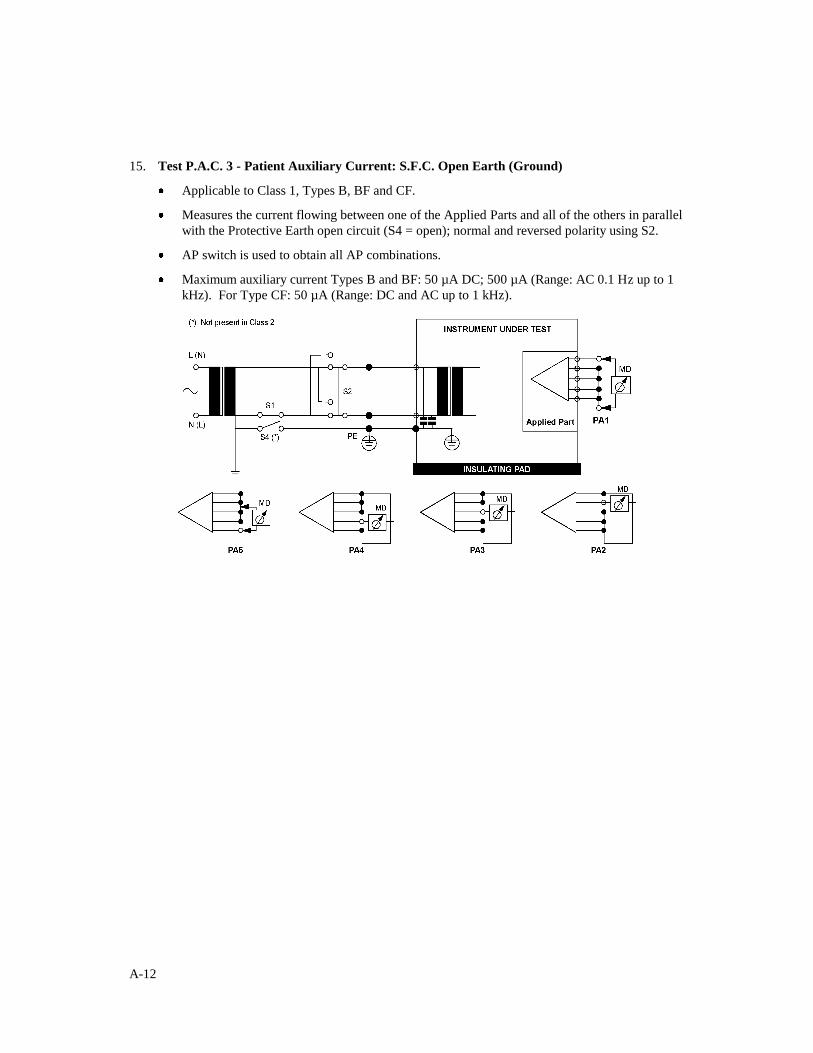
15. Test P.A.C. 3 - Patient Auxiliary Current: S.F.C. Open Earth (Ground)
Applicable to Class 1, Types B, BF and CF.
Measures the current flowing between one of the Applied Parts and all of the others in parallel
with the Protective Earth open circuit (S4 = open); normal and reversed polarity using S2.
AP switch is used to obtain all AP combinations.
Maximum auxiliary current Types B and BF: 50 µA DC; 500 µA (Range: AC 0.1 Hz up to 1
kHz). For Type CF: 50 µA (Range: DC and AC up to 1 kHz).
A-13
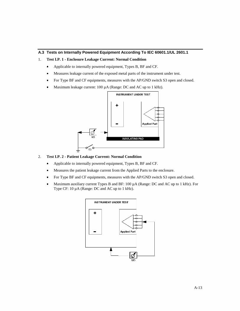
A.3 Tests on Internally Powered Equipment According To IEC 60601.1/UL 2601.1
1. Test I.P. 1 - Enclosure Leakage Current: Normal Condition
Applicable to internally powered equipment, Types B, BF and CF.
Measures leakage current of the exposed metal parts of the instrument under test.
For Type BF and CF equipments, measures with the AP/GND switch S3 open and closed.
Maximum leakage current: 100 µA (Range: DC and AC up to 1 kHz).
2. Test I.P. 2 - Patient Leakage Current: Normal Condition
Applicable to internally powered equipment, Types B, BF and CF.
Measures the patient leakage current from the Applied Parts to the enclosure.
For Type BF and CF equipments, measures with the AP/GND switch S3 open and closed.
Maximum auxiliary current Types B and BF: 100 µA (Range: DC and AC up to 1 kHz). For
Type CF: 10 µA (Range: DC and AC up to 1 kHz).
A-14
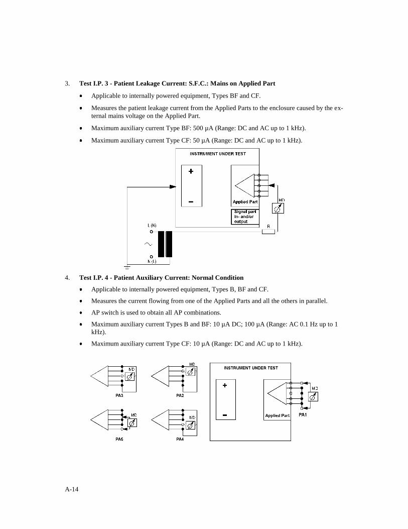
3. Test I.P. 3 - Patient Leakage Current: S.F.C.: Mains on Applied Part
Applicable to internally powered equipment, Types BF and CF.
Measures the patient leakage current from the Applied Parts to the enclosure caused by the ex-
ternal mains voltage on the Applied Part.
Maximum auxiliary current Type BF: 500 µA (Range: DC and AC up to 1 kHz).
Maximum auxiliary current Type CF: 50 µA (Range: DC and AC up to 1 kHz).
4. Test I.P. 4 - Patient Auxiliary Current: Normal Condition
Applicable to internally powered equipment, Types B, BF and CF.
Measures the current flowing from one of the Applied Parts and all the others in parallel.
AP switch is used to obtain all AP combinations.
Maximum auxiliary current Types B and BF: 10 µA DC; 100 µA (Range: AC 0.1 Hz up to 1
kHz).
Maximum auxiliary current Type CF: 10 µA (Range: DC and AC up to 1 kHz).
A-15
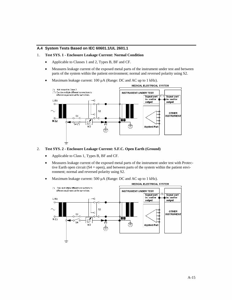
A.4 System Tests Based on IEC 60601.1/UL 2601.1
1. Test SYS. 1 - Enclosure Leakage Current: Normal Condition
Applicable to Classes 1 and 2, Types B, BF and CF.
Measures leakage current of the exposed metal parts of the instrument under test and between
parts of the system within the patient environment; normal and reversed polarity using S2.
Maximum leakage current: 100 µA (Range: DC and AC up to 1 kHz).
2. Test SYS. 2 - Enclosure Leakage Current: S.F.C. Open Earth (Ground)
Applicable to Class 1, Types B, BF and CF.
Measures leakage current of the exposed metal parts of the instrument under test with Protec-
tive Earth open circuit (S4 = open), and between parts of the system within the patient envi-
ronment; normal and reversed polarity using S2.
Maximum leakage current: 500 µA (Range: DC and AC up to 1 kHz).
A-16
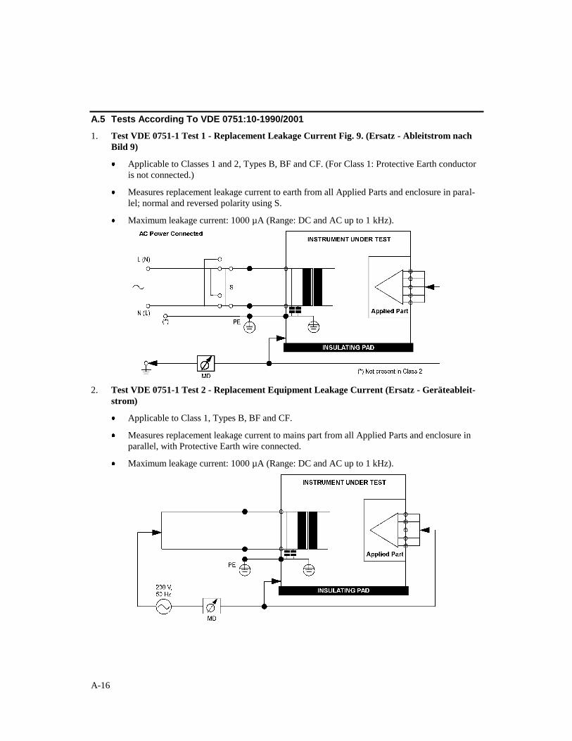
A.5 Tests According To VDE 0751:10-1990/2001
1. Test VDE 0751-1 Test 1 - Replacement Leakage Current Fig. 9. (Ersatz - Ableitstrom nach
Bild 9)
Applicable to Classes 1 and 2, Types B, BF and CF. (For Class 1: Protective Earth conductor
is not connected.)
Measures replacement leakage current to earth from all Applied Parts and enclosure in paral-
lel; normal and reversed polarity using S.
Maximum leakage current: 1000 µA (Range: DC and AC up to 1 kHz).
2. Test VDE 0751-1 Test 2 - Replacement Equipment Leakage Current (Ersatz - Geräteableit-
strom)
Applicable to Class 1, Types B, BF and CF.
Measures replacement leakage current to mains part from all Applied Parts and enclosure in
parallel, with Protective Earth wire connected.
Maximum leakage current: 1000 µA (Range: DC and AC up to 1 kHz).
A-17
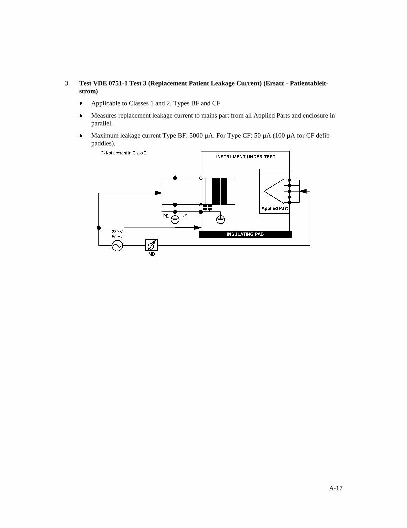
3. Test VDE 0751-1 Test 3 (Replacement Patient Leakage Current) (Ersatz - Patientableit-
strom)
Applicable to Classes 1 and 2, Types BF and CF.
Measures replacement leakage current to mains part from all Applied Parts and enclosure in
parallel.
Maximum leakage current Type BF: 5000 µA. For Type CF: 50 µA (100 µA for CF defib
paddles).


B-1
This page intentionally left blank.

C-1
APPENDIX B: ERROR REPORT FORM, QA-90
QA-90 ELECTRICAL SAFETY ANALYZER ERROR REPORT FORM
USA ____ FRANCE________ GERMANY NORWAY______
1345 Monroe NW 30, rue Paul Claudel Gundastrasse 29 Vegamot 8
Grand Rapids, MI 49505 91000 Evry, France D-63762 Grossostheim N-7048 Trondheim
Phone: (+1) 888 863-8766 Phone: (+33) 1 6078 8899 Phone: (+49) 6026 993975 Phone: (+47) 7395 4700
Fax: (+1) 616 454-3350 Fax: (+33) 1 6078 6839 Fax: (+49) 6026 977079 Fax: (+47) 7395 4701
E-mail: [email protected] E-mail: [email protected] E-mail:[email protected] E-mail: [email protected]
From: (name) Phone: Address: Fax: Date:
QA-90 Error Report Product:
Version:
Type
• Wrong results • Error messages, without reason
• Program stops, no reaction • Wrong responses on commands.
• Other
Description of the situation prior to the error:
Description of the error:
(METRON use internally)
Received date:
Comments: • Critical
Correction date:
• Minor
Ref No.
• Normal

C-2
This page intentionally left blank.
D-1
APPENDIX C: SUGGESTION FORM, QA-90
QA-90 ELECTRICAL SAFETY ANALYZER SUGGESTION FORM
USA ____ FRANCE________ GERMANY NORWAY______
1345 Monroe NW 30, rue Paul Claudel Gundastrasse 29 Vegamot 8
Grand Rapids, MI 49505 91000 Evry, France D-63762 Grossostheim N-7048 Trondheim
Phone: (+1) 888 863-8766 Phone: (+33) 1 6078 8899 Phone: (+49) 6026 993975 Phone: (+47) 7395 4700
Fax: (+1) 616 454-3350 Fax: (+33) 1 6078 6839 Fax: (+49) 6026 977079 Fax: (+47) 7395 4701
E-mail: [email protected] E-mail: [email protected] E-mail:[email protected] E-mail: [email protected]
From: (name) Phone: Address: Fax: Date:
QA-90 Improvement Suggestion Product:
Version:
Type
• One window • Presentation
• Several windows • Options, configuration possibilities
• Documentation • Other
Description of the suggested improvement:
(METRON use internally)
Received date:
Comments:
Correction date:
Ref No.

D-2


