40
2016.08 V1.2 User Manual

2016.08
V1.2User Manual

2 © 2016 DJI. All Rights Reserved.
Using this manual
Legends
Warning Important Hints and Tips Reference
Before FlightThe following tutorials and manuals have been produced to ensure you to make full use of your A3/A3 Pro.1. In the Box2. Safety Guidelines and Disclaimer3. Quick Start Guide4. User Manual
Make sure all of the parts listed in the In the Box document are included in the package.The information in the Safety Guidelines and Disclaimer document affects your safety and your legal rights and responsibilities. Read this entire document carefully to ensure proper configuration before use.Follow the Quick Start Guide step by step to setup and use the A3 or A3 Pro correctly by referring to the User Manual and using the DJI Assistant 2.The A3 and A3 Pro are powerful systems. To make use of all their capabilities, read the user manual thoroughly before configuring the device.
Searching for KeywordsSearch for keywords such as “battery” and “install” to find a topic. If you are using Adobe Acrobat Reader to read this document, press Ctrl+F on Windows or Command+F on Mac to begin a search.
Navigating to a TopicView a complete list of topics in the table of contents. Click on a topic to navigate to that section.
Printing this DocumentThis document supports high resolution printing.
© 2016 DJI. All Rights Reserved. 3
Contents
Using this manual Legends 2
Before Flight 2
Product Profile 4
Introduction 4
System Components 4
Installation 7
Overview 7
Preparation 8
Start the Installation 11
A3/A3 Pro Functions 20
Compass Calibration 20
Flight Functions 21
Protection Functions 24
Flight Limits and Flight Restriction Areas 26
Using with DJI GO app 30
Triple Modular Redundancy 33
SDK 34
Flight Control System Checklist 34
Hardware Checklist 34
DJI Assistant 2 Checklist 34
Flight Safety 35
Appendix 35
LED Indicators 35
Troubleshooting 36
Specifications 37
A3/A3 Pro User Manual
4 © 2016 DJI. All Rights Reserved.
Product Profile
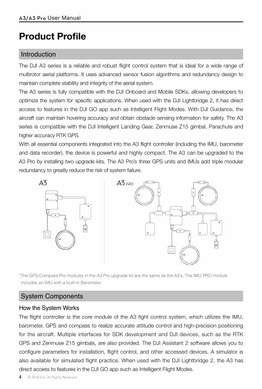
IntroductionThe DJI A3 series is a reliable and robust flight control system that is ideal for a wide range of multirotor aerial platforms. It uses advanced sensor fusion algorithms and redundancy design to maintain complete stability and integrity of the aerial system. The A3 series is fully compatible with the DJI Onboard and Mobile SDKs, allowing developers to optimize the system for specific applications. When used with the DJI Lightbridge 2, it has direct access to features in the DJI GO app such as Intelligent Flight Modes. With DJI Guidance, the aircraft can maintain hovering accuracy and obtain obstacle sensing information for safety. The A3 series is compatible with the DJI Intelligent Landing Gear, Zenmuse Z15 gimbal, Parachute and higher accuracy RTK GPS.With all essential components integrated into the A3 flight controller (including the IMU, barometer and data recorder), the device is powerful and highly compact. The A3 can be upgraded to the A3 Pro by installing two upgrade kits. The A3 Pro’s three GPS units and IMUs add triple modular redundancy to greatly reduce the risk of system failure.
*The GPS-Compass Pro modules in the A3 Pro upgrade kit are the same as the A3’s. The IMU PRO module includes an IMU with a built-in Barometer.
System ComponentsHow the System WorksThe flight controller is the core module of the A3 fight control system, which utilizes the IMU, barometer, GPS and compass to realize accurate attitude control and high-precision positioning for the aircraft. Multiple interfaces for SDK development and DJI devices, such as the RTK GPS and Zenmuse Z15 gimbals, are also provided. The DJI Assistant 2 software allows you to configure parameters for installation, flight control, and other accessed devices. A simulator is also available for simulated flight practice. When used with the DJI Lightbridge 2, the A3 has direct access to features in the DJI GO app such as Intelligent Flight Modes.

A3/A3 Pro User Manual
© 2016 DJI. All Rights Reserved. 5
A3 and A3 Pro PartsFlight ControllerFeature Highlights1. Independent CAN1 and CAN2 ports and API Serial port for the SDK. The CAN1 port is used to
connect the GPS-Compass Pro and DJI devices (e.g. RTK GPS) while the CAN2 port is used to connect SDK devices.
2. Built-in inertial sensors for the measurement of aircraft attitude and built-in pressure sensor for the detection of aircraft altitude.
3. Support for multiple receiver types. If used with the DJI Lightbridge 2, the A3 has direct access to features in the DJI GO app such as Intelligent Flight Modes.
4. M1 to M8 are used to connect the ESCs of the aircraft and iESC for DJI Intelligent ESC communication.
5. 4 independent and configurable output ports and 4 I/O ports. These ports can be customized and connect other DJI devices (e.g. DJI Zenmuse Z15 gimbals, DJI Intelligent Landing Gear) or SDK devices.
Port Diagram
4
5
6
78
3
1
2
9
10
12
11
13
1415
1. IMU1 PortCommunicates with the IMU Pro module.
2. CAN1 PortDedicated DJI CAN-Bus port. Communicates with the A3 GPS-Compass Pro or other DJI devices (e.g. Real Time Kinematic (RTK) GPS system).
3. Orientation Arrow The FC module should be mounted with the arrow pointing in the specified direction (Orientation can be set in the DJI Assistant 2).
4. Status Indicator Indicates the status of the flight controller and triple modular redundancy system.
5. RF Port Communicates with the DJI Lightbridge 2 Air System.
6. iESC Port Communicates with the DJI Smart ESC.
7. M1-M8 Pins Connects to the corresponding ESC PWM port for each motor.
8. LED Port Communicates with the LED module.
9. IMU2 Port Communicates with the IMU Pro module.
10. PMU Port Derives power from the PMU.
11. CAN2 Communicates with an SDK device.
12. API Port Communicates with an SDK device.

A3/A3 Pro User Manual
6 © 2016 DJI. All Rights Reserved.
1. Power Port (9V 3A) Connected to the Flight Controller for power supply.
2. iBAT Communicates with the DJI Intelligent Flight Battery.
3. 3S-12S Derives power from the DJI Intelligent Flight Battery or other LiPo batteries.
GPS-Compass Pro ModuleThe GPS-Compass Pro module has a built-in GPS and compass. The compass is used for geomagnetic field measurements. Compass calibration is required before use. DO NOT use or store the compass in environments with ferromagnetic materials.Note that the GPS-Compass Pro module in the UPGRADE KIT is the same as the one in the A3 package.
1
2
3
PMU ModuleSupported the DJI Intelligent Flight Battery, with built-in PMU providing power for the whole Flight Control System and low voltage protection function.
13
2
LED ModuleThe LED Module has an integrated LED Indicator and Micro USB port.A. The LED is mainly for flight control system status indication during flight (e.g. Flight Mode).B. In addition, there is a Micro USB port for firmware upgrades via DJI Assistant 2.
13. F5-F8 Pins Multifunction PWM I / O ports.
14. F1-F4 Pins Multifunction PWM output ports.
15. S-Bus Port Communicates with a DJI DR16 or S-Bus receiver.
1. Status IndicatorIndicates the status of the GPS-Compass Pro module and triple modular redundancy system.
2. Orientation ArrowThe GPS-Compass Pro module should be mounted with the arrow pointing to the aircraft’s nose.
3. Extended CAN1 PortDedicated DJI CAN-Bus port. Communicates with DJI devices (e.g. Real Time Kinematic (RTK) GPS system).

A3/A3 Pro User Manual
© 2016 DJI. All Rights Reserved. 7
1
2
IMU Pro ModuleIncludes built-in inertial sensors for the measurement of aircraft attitude and a built-in pressure sensor for detecting aircraft altitude. The IMU Pro has been calibrated before delivery and should be used under the specified temperature range. Using the IMU Pro outside the specified temperature range may have a negative effect on the IMU’s performance.
1
32
1. Flight Status IndicatorIndicates the status of the flight control system.
2. Micro USB PortUsed to configure and upgrade the A3 or A3 Pro via DJI Assistant 2.
1. Orientation ArrowThe IMU Pro module should be mounted with the arrow pointing to the specified orientation (Orientation can be set in the DJI Assistant 2).
2. Status IndicatorIndicates the status of the IMU Pro module and triple modular redundancy system.
3. CAN1 GPS PortCommunicates with the GPS-Compass Pro module.
1 Ensure all parts are in good condition.2 Select the A3 or A3 Pro connection.3 Watch the “Installation Demo” and “Connecting the Modules” video tutorials for an overview of
the installation process. Then mount the parts to your airframe and connect them properly.http://www.dji.com/product/a3/video
4 Watch the “How to use DJI Assistant 2” video tutorial for a brief introduction on how to configure the parameters. Then launch the DJI Assistant 2 and configure the parameters.http://www.dji.com/product/a3/video
Installation
OverviewInstallation ProcedureRead this section carefully and follow the procedures below to install your flight control system, otherwise the flight control system may not normally work.

A3/A3 Pro User Manual
8 © 2016 DJI. All Rights Reserved.
PreparationEquipmentEnsure you have a suitable airframe, remote controller system, ESCs and battery to use with the A3 series. You can also prepare optional equipment, e.g. DJI Intelligent Landing Gear, DJI Zenmuse Z15, and DJI Guidance. Below is a list of compatible equipment.A. Airframes
The following airframes are supported. Choose an airframe and assemble it properly. Remember to select the corresponding airframe type in DJI Assistant 2 after assembling the airframe and connecting the cables.
5 Ensure the motor, remote controller channels and Failsafe settings are correct.6 Ensure the devices connected to the flight controller are working normally and correctly set in
DJI Assistant 2.The following diagram shows a completed installation for the S900 (with the PMU module on the bottom of the aircraft’s upper plate).

A3/A3 Pro User Manual
© 2016 DJI. All Rights Reserved. 9
The arrow directions in the above diagram indicate the rotation direction of the motor/propeller. Dark colored arm (s) indicate the direction of the aircraft’s nose.
For coaxial propellers, dark colored propellers are at the top and gray colored propellers are at the bottom. Otherwise, all propellers are at the top.
B. Remote Controller SystemThe following remote controller systems are supported. Whatever type of receiver is used, please make sure that the receiver and remote controller are linked properly before use. Be sure to link the receiver and remote controller according by following all the procedures in the remote controller and receiver user manual, and according to the configurations in DJI Assistant 2.DJI Lightbridge 2DJI Lightbridge 2 lets you use DJI GO to configure the flight control system parameters and utilize Intelligent Flight Modes. DR16The DR16 receiver does not support the Point of Interest (POI) and Waypoint flight modes in DJI GO. S-BusThe S-BUS receiver does not support the Point of Interest (POI) and Waypoint flight modes DJI GO.
There is no need to enable the Failsafe function on the remote controller. Once the receiver loses signal from the remote controller, the controller unit will enter Failsafe mode automatically, and the aircraft will hover or return-to-home & land according to the Failsafe configurations in DJI Assistant 2.
C. ESCESC output should be 400Hz. DJI Propulsion systems are recommended.The iESC port can connect to the DATA port if using the DJI Intelligent ESC.
D. BatteryBoth the 3S-12S LiPo battery and the DJI Intelligent Flight Battery are supported.The DJI Intelligent Flight Battery provides voltage, battery level and battery cell information, as well as low battery level protection.If using a LiPo battery, only the voltage information and low voltage protection are available.
The S900 and DJI Lightbridge 2 are recommended for the A3 series, and are used as examples in this manual.
A3/A3 Pro User Manual
10 © 2016 DJI. All Rights Reserved.
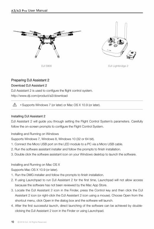
DJI S900 DJI Lightbridge 2
Preparing DJI Assistant 2Download DJI Assistant 2DJI Assistant 2 is used to configure the flight control system.http://www.dji.com/product/a3/download
Supports Windows 7 (or later) or Mac OS X 10.9 (or later).
Installing DJI Assistant 2DJI Assistant 2 will guide you through setting the Flight Control System’s parameters. Carefully follow the on-screen prompts to configure the Flight Control System.
Installing and Running on WindowsSupports Windows 7, Windows 8, Windows 10 (32 or 64 bit).1. Connect the Micro USB port on the LED module to a PC via a Micro USB cable.2. Run the software assistant installer and follow the prompts to finish installation.3. Double click the software assistant icon on your Windows desktop to launch the software.
Installing and Running on Mac OS XSupports Mac OS X 10.9 (or later).1. Run the DMG installer and follow the prompts to finish installation.2. If using Launchpad to run DJI Assistant 2 for the first time, Launchpad will not allow access
because the software has not been reviewed by the Mac App Store.3. Locate the DJI Assistant 2 icon in the Finder, press the Control key and then click the DJI
Assistant 2 icon (or right-click the DJI Assistant 2 icon using a mouse). Choose Open from the shortcut menu, click Open in the dialog box and the software will launch.
4. After the first successful launch, direct launching of the software can be achieved by double-clicking the DJI Assistant 2 icon in the Finder or using Launchpad.

A3/A3 Pro User Manual
© 2016 DJI. All Rights Reserved. 11
DJI Assistant 2 works exactly the same way on Mac OS X and Windows. The DJI Assistant 2 screenshots that appear in this manual are taken from the Windows version.
Start the InstallationImportant: Strictly follow the provided guidelines. Failure to do so may lead to unexpected flight behavior or serious accidents.
Flight Controller System InstallationMounting the Flight ControllerMount the Flight Controller with the Orientation Arrow pointing to the front, back, left or right. Make sure the module is parallel to the aircraft and then fix it onto the aircraft with double-faced adhesive tape. Configure the parameters in DJI Assistant 2 and select the direction in which you mounted the Flight Controller. We recommend mounting the Flight Controller with the Orientation Arrow pointing forward.
The top side should be facing up. DO NOT mount upside-down. Remember to warm up the battery if operating in cold weather.
Mount the flight controller at a low vibration position. The sides of the flight controller should be precisely parallel to the aircraft body. Based on our experience, there is less vibration near the aircraft’s center of gravity.
The flight controller is NOT water-proof or oil-proof. Check the double-faced adhesive tape regularly to ensure the IMU is fixed firmly in place.
Built-in IMU

A3/A3 Pro User Manual
12 © 2016 DJI. All Rights Reserved.
Mounting the GPS-Compass Pro ModuleFollow the procedures below to mount the GPS bracket and the GPS-Compass Pro module. The GPS-Compass Pro module included in the Upgrade kits is the same as the one in the A3 package.1. Use the M2.0×4 screws to assemble the GPS bracket with the Ball End Hex Key assistant.
The longest one is recommended.2. With the M2.5×7 screws and M2.5×3.4 nuts, mount the bracket on the aircraft.
Usage Requirements1. The DJI logo should be facing the sky, with the orientation arrow pointing directly to the nose
direction; otherwise you may experience take off failure.2. Fly the aircraft in an open space without buildings or trees; otherwise the GPS may be affected.3. The compass is sensitive to magnetic interference. Always keep the compass module away
from magnetic fields. Otherwise, the compass module may become damaged and lead the aircraft to work abnormally or even lose control.
Mounting the LED ModuleMount the LED module in a position to ensure it remains visible during flight. The LED bracket included can be used to fix the LED module onto the aircraft.
3. Ensure the GPS-Compass Pro arrow is pointing to the aircraft nose and then fix it onto the top of the GPS bracket. Try to keep it parallel to the aircraft.
A3/A3 Pro User Manual
© 2016 DJI. All Rights Reserved. 13
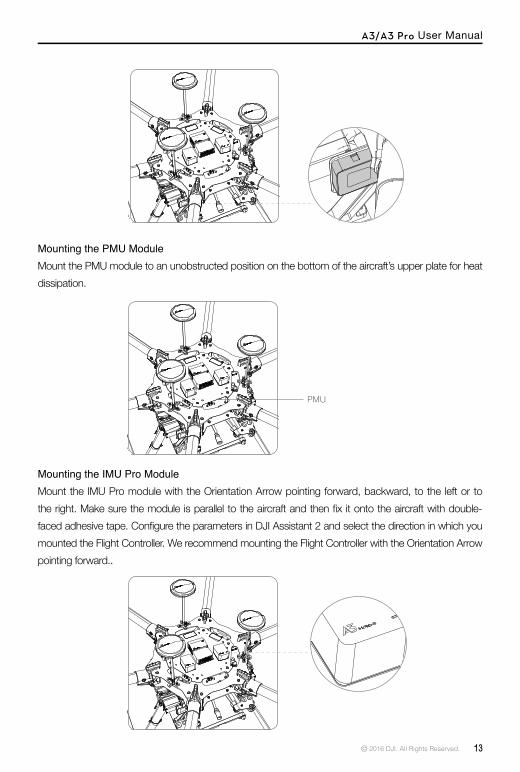
Mounting the PMU ModuleMount the PMU module to an unobstructed position on the bottom of the aircraft’s upper plate for heat dissipation.
Mounting the IMU Pro ModuleMount the IMU Pro module with the Orientation Arrow pointing forward, backward, to the left or to the right. Make sure the module is parallel to the aircraft and then fix it onto the aircraft with double-faced adhesive tape. Configure the parameters in DJI Assistant 2 and select the direction in which you mounted the Flight Controller. We recommend mounting the Flight Controller with the Orientation Arrow pointing forward..
PMU

A3/A3 Pro User Manual
14 © 2016 DJI. All Rights Reserved.
Flight Controller System ConnectionFollow the below diagram to connect the flight control system, and use the cable ties to tidy the cables.
Connecting to the Airframe and its EquipmentEnsure you have a suitable airframe, remote controller system, ESCs and battery to use with the A3 series. Strictly follow the provided guidelines. Failure to do so may lead to unexpected flight behavior or serious accidents.
Connecting to a ReceiverSelect the RF port or the S-Bus port for different types of receivers.
DJI Lightbridge 2Connect the DJI Lightbridge 2 receiver DBUS port to the Flight Controller RF Port.
DBUS Cable II
The flight control system’s shell is connected to the whole system’s ground.

A3/A3 Pro User Manual
© 2016 DJI. All Rights Reserved. 15
DR16 ReceiverConnect the DR16 receiver DBUS port to the Flight Controller S-Bus Port with a servo cable.
S-BUS ReceiverConnect the S-BUS receiver to the Flight Controller S-Bus Port with a servo cable.
Connecting to the ESCsS900 Connection DiagramConnect the M1-M6 ports on the bottom board of the S900 to the M1-M6 ports on the Flight Controller in order.
S- Bus Receiver
Other Airframe Type Connection DiagramConnect the ESC ports to the ESC ports on the Flight Controller. The diagram below uses type V6 for example.

A3/A3 Pro User Manual
16 © 2016 DJI. All Rights Reserved.
Connecting to a BatteryConnect the PMU to the Flight Controller PMU port, and then connect the battery to the PMU.
Connect to Other DJI DevicesThe A3 and A3 Pro are compatible with almost all DJI devices. Connect these optional devices to the flight controller to achieve more functions.
Intelligent Landing GearThe A3 series supports the DJI Intelligent Landing Gear, which can be configured in DJI Assistant 2. You can use a switch to raise or lower the Intelligent Landing Gear.
Mounting and Cable ConnectionEnsure the battery is powered off before connection. Connect the Intelligent Landing Gear to the flight controller’s F1 port, and then configure the settings in DJI Assistant -> DJI Device -> Gear page.
3S-12S

A3/A3 Pro User Manual
© 2016 DJI. All Rights Reserved. 17
UsageWhen enabled, the Intelligent Landing Gear is lowered to the ground by default or in emergency situations (e.g. motor failure tolerance, auto landing). You can use a switch to raise or lower the Intelligent Landing Gear when the aircraft’s flying altitude is above 5m. Important for DJI Assistant Settings1. Be sure to enable and configure the Intelligent Landing Gear function in DJI Assistant first, and
then connect the gear to the F1 port.2. The Gear channel is required to be mapped to a channel on the receiver if the Intelligent Landing
Gear function is enabled in DJI Assistant. Use the F1 port for landing gear output signals.
D-RTK Support for the D-RTK provides high precision position during flight. Configure the D-RTK in DJI Assistant 2.
Mounting and Cable ConnectionEnsure the battery is powered off before connection. Connect the D-RTK to the flight controller’s CAN1 port, and configure the settings in DJI Assistant -> DJI Device -> Gear page.
UsageRefer to the D-RTK user manual for more details.
Zenmuse Z15 GimbalThe A3 and A3 Pro support the DJI Zenmuse Gimbal which can be enabled in DJI Assistant, providing gimbal rotation control during flight.
Mounting and Cable ConnectionEnsure the battery is powered off before connection. Connect the gimbal to the flight controller’s CAN1 port, If used with the DJI Lightbridge 2, no setting requirement. If used with other remote controller, configure the settings in the Zenmuse Z15 Assistant.
CAN1
A3/A3 Pro User Manual
18 © 2016 DJI. All Rights Reserved.
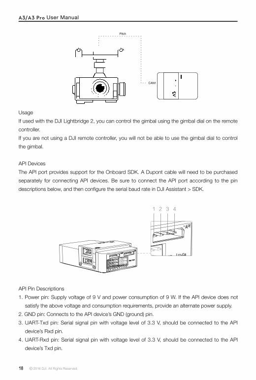
Pitch
CAN1
UsageIf used with the DJI Lightbridge 2, you can control the gimbal using the gimbal dial on the remote controller.If you are not using a DJI remote controller, you will not be able to use the gimbal dial to control the gimbal.
API DevicesThe API port provides support for the Onboard SDK. A Dupont cable will need to be purchased separately for connecting API devices. Be sure to connect the API port according to the pin descriptions below, and then configure the serial baud rate in DJI Assistant > SDK.
1 3 42
API Pin Descriptions1. Power pin: Supply voltage of 9 V and power consumption of 9 W. If the API device does not
satisfy the above voltage and consumption requirements, provide an alternate power supply.2. GND pin: Connects to the API device’s GND (ground) pin.3. UART-Txd pin: Serial signal pin with voltage level of 3.3 V, should be connected to the API
device’s Rxd pin.4. UART-Rxd pin: Serial signal pin with voltage level of 3.3 V, should be connected to the API
device’s Txd pin.

A3/A3 Pro User Manual
© 2016 DJI. All Rights Reserved. 19
ParameterConfigurationWatch the video tutorial for a brief introduction on how to configure the parameters. Then launch DJI Assistant 2 and follow the prompts to complete configuration.
DJI Assistant 2
1 Ensure the flight control system is properly powered on.2 Connect the Micro USB port on the LED module to a PC via a Micro USB cable.3 Run DJI Assistant 2. Note that you may be asked to register for first time use.4 Follow the prompts to upgrade the firmware to the latest version.5 Select the airframe type.6 Configure the IMU and GPS mounting parameters.7 Select the receiver type and configure the channel mapping.8 Make sure the motors are rotating in correct direction. If not, change the rotating direction.9 Configure the function channels.10 Fly in the simulator to check that all functions is working normally.
A3/A3 Pro User Manual
20 © 2016 DJI. All Rights Reserved.
A3/A3 Pro Functions
Compass CalibrationEnsure the compass is calibrated before every flight. Failure to calibrate may lead to poor flight performance or a crash.1. DO NOT attempt to calibrate your compass where there is a chance of strong magnetic
interference. This includes areas where there are massive metal objects, parking structures, steel reinforcements underground, or under bridges.
2. DO NOT carry ferromagnetic materials with you during calibration, such as keys or mobile phones.
3. The compass should always be calibrated when moving from indoor spaces to outdoor spaces.4. After successful calibration, the compass may become abnormal when you place the aircraft on
the ground. This may be because of underground magnetic interference. Move the aircraft to another location and try again.
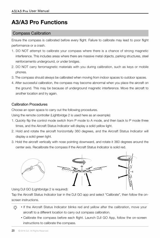
Calibration ProceduresChoose an open space to carry out the following procedures.Using the remote controller (Lightbridge 2 is used here as an example):1. Quickly flip the control mode switch from P mode to A mode, and then back to P mode three
times, and the Aircraft Status Indicator will display a solid yellow light.2. Hold and rotate the aircraft horizontally 360 degrees, and the Aircraft Status Indicator will
display a solid green light.3. Hold the aircraft vertically with nose pointing downward, and rotate it 360 degrees around the
center axis. Recalibrate the compass if the Aircraft Status Indicator is solid red.
If the Aircraft Status Indicator blinks red and yellow after the calibration, move your aircraft to a different location to carry out compass calibration.
Calibrate the compass before each flight. Launch DJI GO App, follow the on-screen instructions to calibrate the compass.
Using DJI GO (Lightbridge 2 is required):Tap the Aircraft Status Indicator bar in the DJI GO app and select “Calibrate”, then follow the on-screen instructions.

A3/A3 Pro User Manual
© 2016 DJI. All Rights Reserved. 21
When to Recalibrate1. When compass data is abnormal, and the Aircraft Status Indicator is blinking red and yellow.2. When flying in a new location, or a location that is different from your last flight.3. When the mechanical structure of the A3/A3 Pro has changed, i.e. the mounting position of
the compass has changed.4. When severe drifting occurs in flight, i.e. the A3/A3 Pro does not fly in a straight line.
Flight FunctionsFlight ModesBelow flight modes are available. Use the Flight Controller mode switch to change the flight mode of the aircraft. The details of each flight mode are found in the section below.Lightbridge 2 is used here as an example.
P mode (Positioning): P mode works best when GPS signal is strong. There are three different states of P mode, which will be automatically selected by the A3/A3 Pro depending on GPS signal strength and Vision Positioning sensors:P-GPS: GPS and Vision Positioning both are available, and the aircraft is using GPS for positioning.P-OPTI: Vision Positioning is available but the GPS signal is not. Aircraft is using only VisionPositioning for hoveringP-ATTI: Neither GPS or Vision Positioning available, aircraft is using only its barometer for positioning, so only altitude is controlled.A mode (Attitude): The GPS and Vision Positioning System is not used for holding position. The aircraft only uses its barometer to maintain altitude. If it is still receiving a GPS signal, the aircraft can automatically return home if the Remote Controller signal is lost and if the Home Point has been recorded successfully.F mode (Function): Intelligent Flight Mode is activated in this mode.M mode (Manual): The GPS and Vision Positioning System is not used for holding position. No barometer is used to maintain altitude. Only use M mode in case of an emergency.
P-OPTI mode is only available when a DJI Vision Positioning System (e.g. DJI GUIDANCE) is used. Refer to the DJI GUIDANCE user manual for more details about how to use P-OPTI mode.
Once the GPS signal is recovered, or the Vision Positioning System available, the Flight Control System can re-enter P-GPS mode or P-OPTI mode.
M mode (Manual) should be enabled in DJI Assistant.

A3/A3 Pro User Manual
22 © 2016 DJI. All Rights Reserved.
Aircraft Status Indicator Description
Normal
Green Flashes Slowly Safe to Fly (P-mode with GPS and Vision Positioning)
×2 Green Flashes Twice Safe to Fly (P-mode with Vision Positioning but without GPS)
Yellow Flashes Slowly Safe to Fly (A mode but No GPS and Vision Positioning)
Flight ControlManual Take-offStart the motors by pulling both control sticks to the bottom inside (or outside) corners. Release the sticks once the motors start. Slowly push the left stick (throttle stick) up to takeoff.
Remote Controller OperationHere are the default flight controls (Mode 2). The left stick controls altitude and rotation, while the right stick controls the forward, backward, left or right movements. The gimbal dial controls the camera’s tilt.
You can customize or change these controls through the DJI GO app.
Manual LandingUse the below method to stop the motors:When the aircraft has landed, push the throttle down and hold. The motors will stop after 3 seconds.
OR
Left Stick Right Stick
UP
Down
Turn RightTurn
Lef
t
Forward
Backward
Right Lef
t
A3/A3 Pro User Manual
© 2016 DJI. All Rights Reserved. 23
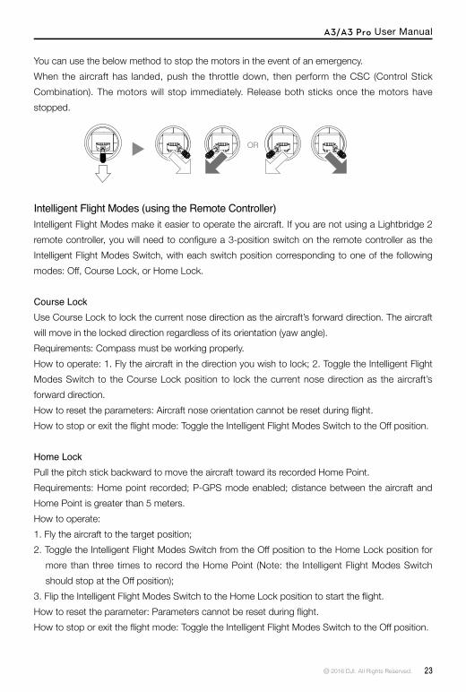
You can use the below method to stop the motors in the event of an emergency.When the aircraft has landed, push the throttle down, then perform the CSC (Control Stick Combination). The motors will stop immediately. Release both sticks once the motors have stopped.
OR
Intelligent Flight Modes (using the Remote Controller)Intelligent Flight Modes make it easier to operate the aircraft. If you are not using a Lightbridge 2 remote controller, you will need to configure a 3-position switch on the remote controller as the Intelligent Flight Modes Switch, with each switch position corresponding to one of the following modes: Off, Course Lock, or Home Lock.
Course LockUse Course Lock to lock the current nose direction as the aircraft’s forward direction. The aircraft will move in the locked direction regardless of its orientation (yaw angle). Requirements: Compass must be working properly. How to operate: 1. Fly the aircraft in the direction you wish to lock; 2. Toggle the Intelligent Flight Modes Switch to the Course Lock position to lock the current nose direction as the aircraft’s forward direction.How to reset the parameters: Aircraft nose orientation cannot be reset during flight. How to stop or exit the flight mode: Toggle the Intelligent Flight Modes Switch to the Off position.
Home LockPull the pitch stick backward to move the aircraft toward its recorded Home Point. Requirements: Home point recorded; P-GPS mode enabled; distance between the aircraft and Home Point is greater than 5 meters. How to operate: 1. Fly the aircraft to the target position; 2. Toggle the Intelligent Flight Modes Switch from the Off position to the Home Lock position for
more than three times to record the Home Point (Note: the Intelligent Flight Modes Switch should stop at the Off position);
3. Flip the Intelligent Flight Modes Switch to the Home Lock position to start the flight.How to reset the parameter: Parameters cannot be reset during flight. How to stop or exit the flight mode: Toggle the Intelligent Flight Modes Switch to the Off position.

A3/A3 Pro User Manual
24 © 2016 DJI. All Rights Reserved.
The aircraft automatically descends and lands if RTH is triggered when the aircraft flies within a 65-foot (20-meter) radius of the Home Point.
The aircraft cannot return to home if the LED is slowly blinking yellow or the GPS does not work.
The aircraft cannot avoid obstacles during Failsafe RTH. Therefore it is important to set a reasonable Failsafe altitude before each flight. Launch the DJI GO app and enter “Camera” view and select “MODE” to set the Failsafe altitude.
The aircraft will stop ascending and immediately return to the Home Point if you move the throttle stick when the aircraft reaches an altitude of 20 m or above during Failsafe.
1 Record Home Point (HP)
Flashing Green
5 Go Home(20m can be set)
Flashing Yellow Rapidly
3 Remote Controller Signal Lost
Flashing Yellow Rapidly
2 Confirm Home Point
Flashing Green
6 Landing after Hovering 15secs
Flashing Yellow Rapidly
4 Signal Lost Lasts 3secs.
Flashing Yellow Rapidly
Height over HP>20m
Elevate to 20m
Height over HP<=20m
20m
Lightbridge 2 not only allows you use the DJI GO app to operate the aircraft, but also use Intelligent Flight Modes, such as Course Lock, Home Lock, Point of Interest (POI) and Waypoints, to capture professional shots during flight.
Protection FunctionsReturn to HomeReturn to Home (RTH) brings the aircraft back to the last recorded Home Point. There are three cases that will trigger the RTH procedure; they are Failsafe RTH, Smart RTH and Low Battery RTH with the DJI Intelligent Battery (Low Voltage RTH with a LiPo battery).
Failsafe RTHFailsafe RTH is activated automatically if the remote controller signal (including video relay signal if DJI Lightbridge 2 used) is lost for more than 3 seconds, provided that the Home Point has been successfully recorded and the compass is working normally. The RTH process may be interrupted and the operator can regain control over the aircraft if a remote controller signal is resumed.

A3/A3 Pro User Manual
© 2016 DJI. All Rights Reserved. 25
Smart RTHUse the RTH button on the remote controller when GPS is available to enable Smart RTH. During the Smart RTH procedure, the aircraft returns to the last recorded Home Point but you may control the aircraft's orientation to avoid collisions. Press the Smart RTH button once to start the process. Press the Smart RTH button again to exit Smart RTH and regain the control.
If using the DJI Lightbridge 2, no additional settings are required for the RTH button. If using another type of remote controller, you must configure the RTH button in DJI Assistant 2.
Low Battery RTH with DJI Intelligent BatteryThe low battery level failsafe is triggered when the DJI Intelligent Flight Battery is depleted to a point that may affect the safe return of the aircraft. Users are advised to return home or land the aircraft immediately when these warnings are shown. Aircraft will automatically return to the Home Point if no action is taken after 10 seconds countdown. Cancel the RTH procedure by pressing once on the RTH button. The thresholds for these warnings are automatically determined based on the current aircraft altitude and its distance from the Home Point. Aircraft will land automatically only if the current battery level can support the aircraft in landing on the ground from the current altitude. Use the remote controller to control the aircraft’s orientation during the landing process.
Low Battery RTH with LiPo batteryWith LiPo battery, the Low Voltage RTH will be triggered when the LiPo battery is depleted to a point that may affect the safe return of the aircraft.
Attitude Control When One Motor Output FailsFor multirotor aircraft, the A3/A3 Pro flight control system can control the aircraft’s attitude when one motor fails:1. During flight, the aircraft with A3/A3 Pro flight control system is attitude controllable when one
motor output fails2. The motor will not start before take-off. (DJI Intelligent ESCs are required for communication.)
When the critical battery level warning activates and the aircraft is descending to land automatically, you may push the throttle upward to hover the aircraft and navigate it to a more appropriate location for landing.
Color zones and markers on the battery level indicator reflect estimated remaining flight times and are adjusted automatically, according to the aircraft’s current status. (Shown in app when using the Lightbridge 2)

A3/A3 Pro User Manual
26 © 2016 DJI. All Rights Reserved.
Flight Limits and Flight Restriction AreasFlight limits on height and distance can be set. The details of these flight limits are described in the following section.All unmanned aerial vehicle (UAV) operators should abide by all regulations from such organizations as the ICAO (International Civil Aviation Organization), FAA and their own national airspace regulations. For safety reasons, the flight limits function is enabled by default to help users use this product safely and legally. The flight limits function includes height limits, distance limits and No Fly Zones. When operating in P Mode, height, distance limits and No Fly Zones work together to manage flight. In A mode only height limits work and flights cannot go higher than 120 meters* (can be set up to 500 meters in the Assistant or DJI GO app).*It is 50 meters if the GPS Level does not reach 3-level (or above) during flight.
Select Course Lock or Home Lock mode to fly the aircraft to a safe area to land when the aircraft is far away, or the attitude can’t be recognized.
Propulsion System ProtectionLow battery and overweight aircraft warnings are provided in the DJI GO app.
Max Height & Radius LimitsMax Height & Radius limit flying height and distance. Once complete, your aircraft will fly in a restricted cylinder that is determined by these settings. The tables below show the details of these limits.
Maximum Flight Altitude Max Radius
Home Point
Height of aircraft when turned on
GPS Signal Strong Slowly Blinking Green
Flight Limits DJI GO app Aircraft Status Indicator
Maximum Flight Altitude
Aircraft's altitude cannot exceed the specified value.
Warning: Height limit reached.
None.
Max RadiusFlight distance must be within the max radius.
Warning: Distance limit reached.
None.

A3/A3 Pro User Manual
© 2016 DJI. All Rights Reserved. 27
GPS Signal Weak Slowly Blinking Yellow
Flight Limits DJI GO app Aircraft Status Indicator
Maximum Flight Altitude
Height is restricted to 400 feet. (120m) and under.
Warning: Height limit reached.
None.
Max Radius
No limits
If the aircraft flies out of the limit, you can still control the aircraft, but you cannot fly it any farther.
If the aircraft flies out of the max radius it will fly back within range automatically when GPS signal is strong.
No-Fly Zones
All No-Fly Zones are listed on the DJI official website at http://www.dji.com/flysafe/no-fly. No-Fly Zones are divided into Airports and Restricted Areas. Airports include major airports and flying fields where manned aircraft operate at low altitudes. Restricted Areas include border lines between countries or sensitive institute. The details of the No-Fly Zones are explained as follow:
Airport(1) Airport No-Fly Zone are comprised of Take-off Restricted zones and Restricted Altitude Zones.
Each zone features circles of various sizes. (2) R1 miles (value of the R1 depends on the size and shape of the airport) around the airport is a
Take-off restricted zone, inside of which take off is prevented. (3) From R1 mile to R1 + 1 mile around the airport the flight altitude is limited to a 15 degree
inclination.Starting at 65 feet (20 meters) from the edge of airport and radiating outward. The flight altitude is limited to 1640 feet (500 meters) at R1+1 mile
(4) When the aircraft enters within 320 feet (100 meters) of No-Fly Zones, a warning message will appear on the DJI GO app.

A3/A3 Pro User Manual
28 © 2016 DJI. All Rights Reserved.
R1
66 feet
1 mile320 feet R2
1640 feet
100m R
Restricted Area(1) Restricted Areas does not have flight altitude restrictions. (2) R miles around the designated restriction area is a Take-off Restricted area. Aircraft cannot
take off within this zone. The value of R varies based on the definition of the restricted areas. (3) A “warning zone” has been set around the Restricted Area. When the aircraft approaches
within 0.062 miles (100 m) of this zone, a warning message will appear on the DJI GO app.
R1
66 feet
1 mile320 feet R2
1640 feet
100 m R

A3/A3 Pro User Manual
© 2016 DJI. All Rights Reserved. 29
GPS Signal Strong Blinking Green
Zone Restriction DJI GO app Prompt Aircraft Status Indicator
No-fly Zone
Motors will not start.Warn ing: You are in a No- f l y zone . Take o f f prohibited.
Red flashing
If the aircraft enters the restricted area in A-mode, but is switched to P-mode, the aircraft will automatically descend, land, and stop its motors.
Warning: You are in a no-fly zone. Automatic landing has begun.
Restricted-altitude flight
zone
If the aircraft enters the restricted area in A-mode, but is switched to P-mode, it will descend to an appropriate altitude and hover 15 feet below the altitude limit.
R1: Warning: You are in a restricted zone. Descending to safe altitude. R2: Warning: You are in a restricted zone. Maximum flight altitude is restricted to between 20m and 500m. Fly cautiously.
Warning zone No flight restriction applies, but there will be a warning .
Warning: You are approaching a restricted zone, Fly cautiously.
Free zoneNo restrictions. None. None.
Semi-automatic descent: All stick commands are available except the left stick command during the descent and landing process. Motors will stop automatically after landing.
When flying in a safety zone, the aircraft's status indicator will blink red rapidly and continue for 3 seconds, then switch to indicate current flying status and continue for 5 seconds at which point it will switch back to blinking red.
For safety reasons, please do not fly close to airports, highways, railway stations, railway lines, city centers, or other sensitive areas. Fly the aircraft only within your line of sight.

A3/A3 Pro User Manual
30 © 2016 DJI. All Rights Reserved.
Using with DJI GO appIntelligent Flight Modes are available in the DJI GO app when using the DJI Lightbridge 2.
Download the DJI GO AppSearch “DJI GO” on the App Store or Google Play and download the app to your mobile device.For the best user experience, please use mobile devices with iOS 8.0 (or higher) and Android 4.1.2 (or higher).
Beginner ModeThe A3/A3 Pro will enter Beginner Mode the first time you use the DJI GO app, which can be canceled on the “MODE” page. In Beginner Mode, the Max Height and Max Distance are restricted to 30 meters.
Auto Take-offUse auto take-off to take off your aircraft automatically if the Aircraft Status Indicator is blinking green. Follow the steps below to use auto take-off:1. Launch DJI GO app, enter “Camera” view.2. Ensure the aircraft is in “P” mode.3. Go through the pre-flight checklist.4. Tap“ ”, and confirm flight conditions. Slide to confirm and take-off.5. Aircraft takes off and hovers at 1.2 meters above ground.
Auto-LandingUse auto-landing to land your aircraft automatically if the Aircraft Status Indicator is blinking green.Follow the steps below to use auto-landing:1. Ensure the aircraft is in “P” mode.2. Check the landing area condition before tapping “ ”, to perform landing.3. Aircraft lowers the landing gear and proceed to land automatically.
Updating the Home PointThere are two ways for updating the Home Point.1. Update the Home Point via DJI GO app when using with Lightbridge 2.2. Quickly flip the F-switch more than three times to update the Home Point when using a non-
DJI receiver.The aircraft status indicator blinks green to show Home Point is set successfully.

A3/A3 Pro User Manual
© 2016 DJI. All Rights Reserved. 31
Return to HomeSmart RTH, Low Battery RTH and Failsafe RTH are also available in the DJI GO app.Smart RTHPress the Return-To-Home button to bring the aircraft back to the Home Point. Tap again to stop the procedure.
Low Battery RTH*The low battery level* failsafe is triggered when the DJI Intelligent Flight Battery is depleted to a point that may affect the safe return of the aircraft. Users are advised to return home or land the aircraft immediately when these warnings are shown. DJI GO will advise users to return the aircraft to the Home Point when the low battery warning is triggered. Aircraft will automatically return to the Home Point if no action is taken after a 10-second countdown. Cancel the RTH by pressing once on the RTH button. The thresholds for these warnings are automatically determined based on the current aircraft altitude and its distance from the Home Point.Aircraft will land automatically if the current battery level can only support the aircraft to land to the ground from the current altitude. Use the remote controller to control the aircraft’s orientation during the landing process.
When the critical battery level warning activates and the aircraft is descending to land automatically, you may push the throttle upward to hover the aircraft and navigate it to a more appropriate location for landing.
Color zones and markers on the battery level indicator reflect estimated remaining flight time and are adjusted automatically, according to the aircraft’s current status.
* The low voltage failsafe is triggered if using a LiPo battery.
Failsafe RTHThe aircraft will not avoid obstacles while it is returning to the Home Point, and an appropriate RTH altitude MUST be set before flight. Launch the DJI GO app and enter Camera view and select “MODE” to set the Failsafe altitude. You should also use the control sticks to guide the aircraft. Refer to the Safety Guidelines and Disclaimer for more details.
Intelligent Flight Modes (in DJI GO app)Course LockLock the current nose direction as the aircraft’s forward direction. The aircraft will move in the locked directions regardless of its orientation (yaw angle).Conditions of Use: Compass is working normally.How to operate: Control the aircraft nose orientation-> Tap the Course Lock icon to start the Course Lock flight.
A3/A3 Pro User Manual
32 © 2016 DJI. All Rights Reserved.
How to reset the parameter: Aircraft nose orientation cannot be reset during flight.How to stop or exit the flight mode: Click the “Exit” button during flight.
Home LockPull the pitch stick backward to move the aircraft toward its recorded Home Point.Conditions of Use: Home point recorded; in the P-GPS mode; distance between the aircraft and home point is larger than 5 meters. How to operate: Tap the Home Lock icon to start.How to reset the parameter: None.How to stop or exit the flight mode: Click the “Exit” button during flight.
POI (point of interest)The aircraft will orbit around the subject automatically to allow the operator can be more focus on framing their shoot on the subject in Point of Interest.Conditions of Use: in the P-GPS mode; distance between the aircraft and interest point is larger than 5 meters and smaller than 10 meters.How to operate: Set the interest point -> Operate the aircraft to set the distance and the flight velocity -> Tap the POI icon to start the flight.How to reset the parameter: The distance and the flight velocity can be changed during the flight when you operate the aircraft.How to stop or exit the flight mode: Click the “Exit” button during flight.
WaypointsRecord a flight path, then the aircraft will fly along the same path repeatedly while you control the camera and orientation. The flight path can be saved and re-applied in the future.Conditions of Use: in the P-GPS mode; Distance between the way points is larger than 5 meters and less than 500 meters; automatically detect the battery level for the smart flight battery (or voltage for LiPo batteries).How to operate: Operate the aircraft to the target position and set the aircraft nose orientation -> Tap to record the waypoints-> Set the Waypoint mode (Consistent with record, Consistent with route, Free) -> Set the flight velocity and Failsafe option->Save in the App-> Start.How to reset the parameter: The aircraft orientations are different in each mode. Operate the aircraft to fly forwards or backwards.How to stop or exit the flight mode: Click the “Exit” button during flight.
Difference between the three modes:Free: The aircraft nose can be changed during the waypoint flight. Consistent with record: Aircraft nose orientation of every waypoint are pre-recorded. And the

A3/A3 Pro User Manual
© 2016 DJI. All Rights Reserved. 33
Triple Modular RedundancyWith two additional IMU Pro and GPS-Compass Pro modules, the A3 Pro provides triple modular redundancy, improving the system’s anti-risk performance. System status is indicated by LEDs on the GPS-Compass Pro, IMU Pro and Flight Controller modules.
aircraft nose will automatically change to the recorded orientation during flight.Consistent with record: Aircraft nose orientation keep the same as the route direction. The aircraft nose will automatically change during flight.
If the detected battery level is too low, the aircraft will not enter the Waypoints flight mode.
IOSDDJI Lightbridge 2 MUST be connected to for the built-in iOSD to work. Most flight information is displayed on-screen in the DJI GO app.Information displayed includes battery level/voltage, flight velocity, height, distance from the home point, horizontal attitude, GPS satellite number, etc. iOSD and video information are superposed on the receiver, making iOSD data clearly visible and bringing you a more involved flight experience.
A3/A3 Pro supports DJI iOSD Mark II and iOSD mini.
Blinks Twice
Blinks Once
Blinks Three Times
A3/A3 Pro User Manual
34 © 2016 DJI. All Rights Reserved.
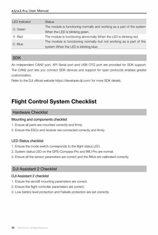
SDKAn independent CAN2 port, API Serial port and USB OTG port are provided for SDK support. The CAN2 port lets you connect SDK devices and support for open protocols enables greater customization.Refer to the DJI official website https://developer.dji.com/ for more SDK details.
LED Indicator Status
GreenThe module is functioning normally and working as a part of the system When the LED is blinking green.
Red The module is functioning abnormally When the LED is blinking red.
BlueThe module is functioning normally but not working as a part of the system When the LED is blinking blue.
Flight Control System Checklist
Hardware ChecklistMounting and components checklist1. Ensure all parts are mounted correctly and firmly.2. Ensure the ESCs and receiver are connected correctly and firmly.
LED Status checklist1. Ensure the mode switch corresponds to the flight status LED.2. System status LED on the GPS-Compass Pro and IMU Pro are normal.3. Ensure all the sensor parameters are correct and the IMUs are calibrated correctly.
DJI Assistant 2 ChecklistDJI Assistant 2 checklist1. Ensure the aircraft mounting parameters are correct.2. Ensure the flight controller parameters are correct.3. Low battery level protection and Failsafe protection are set correctly.

A3/A3 Pro User Manual
© 2016 DJI. All Rights Reserved. 35
Flight SafetyIt is important to understand basic flight guidelines for the safety of both you and those around you. Refer to the Disclaimer and Safety Guidelines for more information.
Appendix
LED IndicatorsFlight Status LED Indicator
LED Description Blinking Red, Green and Yellow
Alternatively The system is running a diagnostic test.
×4 Blinking Yellow Four Times The system is warming up.
Blinking Green Slowly Safe to fly, GPS working
Blinking Yellow Slowly P-ATTI or ATTI mode
×2 Blinking Green Quickly Twice VPS working, no GPS
Blinking Purple Twice Manual mode
Blinking Blue (Alternates with flight mode patterns)
Positioning with D-RTK
Blinking Blue Rapidly for 1.5 seconds Switching devices (IMU or GPS modules) for the modular redundancy system
Blinking Green Rapidly for 1.5 secondsHome Point/POI/Course Orientation is set successfully
Blinking Yellow (Alternates with other flight mode and D-RTK patterns)
Intelligent Flight Modes
Blinking Yellow Rapidly Remote controller signal lost
Blinking Red Slowly Low battery warning
Blinking Red Rapidly Critically low battery warning
Blinking Red Rapidly for 0.6 second when performing CSC
Large IMU bias or IMU initialization
—— Solid Red Critical error
Blinking Red and Yellow Alternatively Compass calibration required

A3/A3 Pro User Manual
36 © 2016 DJI. All Rights Reserved.
Troubleshooting1. LED Status checklistEnsure the mode switch corresponds to the flight status LED.Ensure the system status LEDs on the GPS-Compass Pro and IMU Pro are normal.Ensure all the sensor parameters are correct and the IMUs are calibrated correctly.
2. IMU calibration failure.Ensure the aircraft is not moved during calibration.Ensure the aircraft is placed level during calibration.
3. Battery detection error.Connect to DJI Assistant 2 to ensure the battery type is correct.
4. Compass calibration failure.Restart the battery if compass calibration failed.Connect to DJI Assistant 2 to ensure the channel mapping of the flight mode switch is correct.Connect to DJI Assistant 2 to ensure the compass Mod value is normal.
5. Failed to exit the SD card read mode after reading the SD card successfully.Restart the battery of the aircraft.
LED Indicator Status
GreenThe module is functioning normally and working as a part of the system When the LED is blinking green.
Red The module is functioning abnormally When the LED is blinking red.
BlueThe module is functioning normally but not working as a part of the system When the LED is blinking blue.
GPS-Compass Pro/IMU Pro/Flight Controller LED Indicator
A3/A3 Pro User Manual
© 2016 DJI. All Rights Reserved. 37
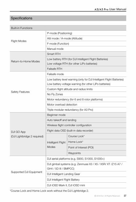
Specifications
Built-in Functions
Flight Modes
P-mode (Positioning)
Atti mode / A-mode (Attitude)
F-mode (Function)
Manual mode
Return-to-Home Modes
Smart RTH
Low battery RTH (for DJI Intelligent Flight Batteries)Low voltage RTH (for other LiPo batteries)
Failsafe RTH
Safety Features
Failsafe mode
Low battery level warning (only for DJI Intelligent Flight Batteries)Low battery voltage warning (for other LiPo batteries)
Custom flight altitude and radius limits
No Fly Zones
Motor redundancy (for 6 and 8 rotor platforms)
Motor overload detection
Triple modular redundancy (for A3 Pro)
DJI GO App(DJI Lightbridge 2 required)
Beginner mode
Auto takeoff and landing
Wireless flight controller configuration
Flight data OSD (built-in data recorder)
Intelligent Flight Modes
Course Lock*
Home Lock*
Point of Interest (POI)
Waypoints
Supported DJI Equipment
DJI aerial platforms (e.g. S900, S1000, S1000+)
DJI gimbal systems (e.g. Zenmuse X3 / X5 / X5R/ XT /Z15 A7 / GH4 / 5D Ⅲ / BMPCC)
DJI Intelligent Landing Gear
DJI Intelligent Flight Battery
DJI iOSD Mark II, DJI iOSD mini
*Course Lock and Home Lock work without the DJI Lightbridge 2.

A3/A3 Pro User Manual
38 © 2016 DJI. All Rights Reserved.
Peripheral
Supported Airframes4-rotor: I4, X46-rotor: I6, V6, Y6, IY68-rotor: X8, I8, V8
Supported ESC output 400 Hz refresh frequency
Supported ReceiversDJI Lightbridge 2DJI DR16S-Bus
Recommended BatteriesDJI Intelligent Flight Battery 3S-12S LiPo battery
Required Operation SystemWindows 7, 8 or 10 (32 or 64 bit)Mac OS X 10.9 or later
SDKMobile SDKOnboard SDK
Onboard SDK Ports API, CAN2*
Expansion PortsF1-F4 ports for outputF5-F8 ports for I/O*
Electrical & Mechanical
Rated PowerA3: 5 WA3 Pro: 10 W
Rated Peak PowerA3: 8 WA3 Pro: 16 W
Input Voltage Range 10.5 – 52 V
Static ElectricityAD: ±8 kVCD: ±4 kV
Operating Temperature 14° to 113° F (-10° to 45° C)
Weight
Flight Controller: 66 gGPS-Compass Pro: 60 gLED Module: 15 gIMU Pro: 40 gPMU: 45 g
*Coming soon.

A3/A3 Pro User Manual
© 2016 DJI. All Rights Reserved. 39
Optimized Flight Performance (subject to airframe type and payload)
Hovering Accuracy (In P-Mode)Vertical: ± 0.5 mHorizontal: ± 1.5 m
Max Wind Resistance 10 m/s
Max Yaw Angular Velocity 150°/s
Max Pitch Angle 35°
Max Ascent Velocity 5 m/s
Max Descent Velocity 4 m/s
Dimensions
Flight Controller: 64 mm × 42 mm × 19.5 mmGPS-Compass Pro: 61 mm (diameter) × 13 mmLED Module: 27 mm × 27 mm × 8 mmIMU Pro: 34 mm × 26.5 mm × 20 mmPMU: 51 mm × 34 mm × 13.5 mm

© 2016 DJI. All Rights Reserved.
This content is subject to change.
Download the latest version fromhttp://www.dji.com/product/a3
If you have any questions about this document, please contact DJI by sending a message to [email protected].
DJI Supporthttp://www.dji.com/support


